development of an analyzing and tuning methodology for the
TRANSCRIPT

applied sciences
Article
Development of an Analyzing and TuningMethodology for the CNC Parameters Based onMachining Performance
Ben-Fong Yu * and Jenq-Shyong Chen
Department of Mechanical Engineering, National Chung Hsing University, 40227 Taichung, Taiwan;[email protected]* Correspondence: [email protected]; Tel.: +886-4-2284-0165 (ext. 4032)
Received: 14 March 2020; Accepted: 11 April 2020; Published: 14 April 2020�����������������
Abstract: This paper proposes the development of a tuning methodology which can set the propervalues of the Computer Numerical Control (CNC) parameters to achieve the required machiningperformance. For the conventional operators of machine tools, the CNC parameters were hardto be adjusted to optimal settings, which was a complicated and time-consuming task. To savetime in finding optimal CNC parameters, the objective of this research was to develop a practicalmethodology to tune the CNC parameters effectively for easy implementation in the commercialCNC controller. Firstly, the effect of the CNC parameters in the CNC controller on the tool-pathplanning was analyzed via experiments. The machining performance was defined in the high-speed(HS) mode, the high-accuracy (HP) mode, and the high-surface-quality (HQ) mode, according to thedynamic errors of several specified paths. Due to the CNC parameters that have a particularly criticaleffect on the dynamic errors, the relationship between the CNC parameters and the dynamic errorswas validated by the measured data. Finally, the tuning procedure defined the anticipated dynamicerrors for the three machining modes with the actual machine. The CNC parameters will correspondwith anticipated dynamics errors based on several specified paths. The experimental results showedthat the HS mode was the fastest to complete the path, and the completion time of the HP and HQmodes were increased by 37% and 6%, respectively. The HP mode had the smallest dynamic errorsthan other modes, and the dynamic errors of the HS and HQ modes are increased by 66% and 16%.In the HQ mode, the motion oscillation was reduce significantly, and the tracking error of the HS andHP modes were increased by 85% and 28%. The advantage of the methodology is that it simplifiesset-up steps of the CNC parameters, making it suitable for practical machine applications.
Keywords: CNC parameters; machining mode; high speed; high accuracy; high surface quality
1. Introduction
There are many kinds of products produced with Computer Numerical Control (CNC) machinetools. According to the workpiece weight, geometric shape, material, tools, and cutting conditions, theoperator needs to estimate the proper manufacturing processes, so the machining requirements willnot be the same. Some products require an extremely smooth surface, such as plastic injection molds,while others require high geometrical accuracy and little tolerance, such as precision machine elements(cf., gears), and still others require high cutting efficiency (i.e., material removal rate) and allow largertolerance, such as the aluminum brackets for bicycle or aerospace. This situation is why machine toolshave focused on how to accomplish high-surface-quality (HQ), high-accuracy (HP) and high-speed(HS) machining. Most of the commercial CNC machine tools are equipped with a standard set of CNCparameters, which are not changed according to the different machining demands. The standard set of
Appl. Sci. 2020, 10, 2702; doi:10.3390/app10082702 www.mdpi.com/journal/applsci

Appl. Sci. 2020, 10, 2702 2 of 21
CNC parameters of machine tools are created by their manufacturers. However, the tuning of CNCparameters has to require a lot of domain knowledge, including the most basic theories, such as statics,dynamics, kinematics, mechanism, motion control, etc. More advanced knowledge also includes thequality of Computer Aided Manufacturing (CAM), interpolation, machine performance, tool geometry,cutting conditions, etc. That is why the machine operators cannot easily tune the CNC parametersto match their product for relevant machining requirements. Figure 1 shows the architecture of feedmotion processing sequence in the commercial CNC machine tools in this study. Firstly, the CAMmodel generates the corresponding Numerical Control (NC) code. The position command of the NCcode (Sg) would be interpreted by the CNC controller for tool-path planning in interpolator, and thatgenerates the motion trajectory based on the CNC parameters. Therefore, the CNC parameters includethe velocity, acceleration, and jerk for their path statements, such as straight, corner, and arc paths.An algorithm on the tool-path planning produced the kinematic profiles of their relevant position,velocity, acceleration, and jerk based on NC code and CNC parameters. According to the kinematicprofiles, each servo axis would move along the trajectory motion that was defined as position command(Sc). The Sc drives the feed drive system of the machine tools via servo loop. The feedback signalwas defined as the actual position (Sa) for the feed drive system in the machine tools. Finally, the realworkpiece would be produced based on the tool path, tool, material, and cutting conditions. The loopof the blue arrow in Figure 1 has been widely used in all machine tools.Appl. Sci. 2020, 10, x FOR PEER REVIEW 3 of 22
Figure 1. The goal architecture of the processing sequence in this study.
A number of studies have analyzed the effects of the tool-path planning to follow the desired contours, and jerk control strategies have been proposed [1–4]. According to the path distance and feedrate of the NC code, the form of the acceleration profile must first be defined by the presetting of jerk and acceleration for CNC parameters; the acceleration profile of the triangle or trapezoid was planned. Some literature introduced the advanced method for interpolation, such as Non-Uniform Rational B-Splines (NURBS) and Bazier [5,6]. Sencer et al. [7] literature presented the algorithm with learning for NC code re-established. Therefore, the objective of the tool-path planning is to ensure the feedrate can be smoothed for precision results as required. Tapie et al. [8] proposed the circular tests for high speed machining, and proposed the limit values of jerk, acceleration, and circular velocity. However, the tool path is not only a circular path, but also contains straight and corner paths. This study did not discuss the other CNC parameters. Pateloup et al. [9] presented the corner optimization. However, it proposed the corner with arc path for pocket machining. In general, the corner path consists of two short lines, and the limit of corner velocity avoids the vibration after the corner motion. This study did not obtain the corner velocity of CNC parameters.
Andolfatto et al. [10] presented the dynamic errors at the tool center point, and included the contour error caused by a closed loop feed drive system and actual error from the machine structure that defined the feedback position to relate tool center point. However, this study did not discuss the error caused by CNC parameters. Lee et al. [11] also established a servo parameter tuning method based on the corner error. The experimental results based on the corner error measurements showed that the proposed tuning methods are very effective in improving the corner accuracy of a three-axis high-speed CNC machine tool. Parenti et al. [12] proposed the acceleration spectrum of the acceleration profiles which exert significant effects on the behavior of the dynamic errors in the CNC machine tools at the tool center point. Bringmann et al. [13] introduced a measurement device based on the “R-test” for measuring displacements in the three linear degrees of freedom, and for evaluating the dynamic errors of the machine at the tool center point. The CNC parameters, such as jerk and acceleration limits, can be set to obtain the required dynamic path accuracy. However, the proposed tuning method was proven only for the HP mode, and not for the HQ or HS mode. Li et al. [14]
Figure 1. The goal architecture of the processing sequence in this study.
The goal of this study was to analyze the relationships among machining modes, CNC parameters,and dynamic errors, followed by developing the tuning procedure which can tune the proper valuesof the CNC parameters to match the selected machining mode; it is shown on the red dot frame inFigure 1. Firstly, an analysis of the CNC parameters based on algorithm of tool-path planning inthe conventional controller, and the principle of tool-path planning was organized. It proposed thedynamic errors chain that we have to observe in actual machine tools. In this paper, dynamic errorssignify the deviation between the position of the NC code and the actual position of the feed drive

Appl. Sci. 2020, 10, 2702 3 of 21
system. It contains two parts: One part is the difference between the Sg and Sc, another part is thedifference between the Sc and Sa. Secondly, we experimented on the machining modes with differentCNC parameters and collected data. It presents a tuning criteria for the three machining modes andCNC parameters. Finally, this study adjusted the CNC parameters and analyzed the experimentalresults with an actual machine to develop the tuning methodology for machining modes. It proposesthe tuning methodology and procedure for the CNC parameters based on machining requirements.
A number of studies have analyzed the effects of the tool-path planning to follow the desiredcontours, and jerk control strategies have been proposed [1–4]. According to the path distance andfeedrate of the NC code, the form of the acceleration profile must first be defined by the presettingof jerk and acceleration for CNC parameters; the acceleration profile of the triangle or trapezoid wasplanned. Some literature introduced the advanced method for interpolation, such as Non-UniformRational B-Splines (NURBS) and Bazier [5,6]. Sencer et al. [7] literature presented the algorithm withlearning for NC code re-established. Therefore, the objective of the tool-path planning is to ensure thefeedrate can be smoothed for precision results as required. Tapie et al. [8] proposed the circular testsfor high speed machining, and proposed the limit values of jerk, acceleration, and circular velocity.However, the tool path is not only a circular path, but also contains straight and corner paths. Thisstudy did not discuss the other CNC parameters. Pateloup et al. [9] presented the corner optimization.However, it proposed the corner with arc path for pocket machining. In general, the corner pathconsists of two short lines, and the limit of corner velocity avoids the vibration after the corner motion.This study did not obtain the corner velocity of CNC parameters.
Andolfatto et al. [10] presented the dynamic errors at the tool center point, and included thecontour error caused by a closed loop feed drive system and actual error from the machine structurethat defined the feedback position to relate tool center point. However, this study did not discuss theerror caused by CNC parameters. Lee et al. [11] also established a servo parameter tuning methodbased on the corner error. The experimental results based on the corner error measurements showedthat the proposed tuning methods are very effective in improving the corner accuracy of a three-axishigh-speed CNC machine tool. Parenti et al. [12] proposed the acceleration spectrum of the accelerationprofiles which exert significant effects on the behavior of the dynamic errors in the CNC machine toolsat the tool center point. Bringmann et al. [13] introduced a measurement device based on the “R-test”for measuring displacements in the three linear degrees of freedom, and for evaluating the dynamicerrors of the machine at the tool center point. The CNC parameters, such as jerk and acceleration limits,can be set to obtain the required dynamic path accuracy. However, the proposed tuning method wasproven only for the HP mode, and not for the HQ or HS mode. Li et al. [14] presented the differentfeedrate effect on the dynamic errors of the feed drive system. This proposal was useful for HQ mode,but this study did not have any solutions to tune the other modes.
Some studies have analyzed the influence of motion errors for the machining performance. Somescholars focus on the dynamic errors caused by tool geometrics [15–17]. It is dependent on a largermachine and the dynamic errors’ source on machine structure. Mia et al. [18] presented intelligentoptimization of hard-turning parameters. This paper proposed the evolutionary algorithms for cuttingconditions. Their dynamic errors adjust method was to change the cutting conditions. The maindisadvantage is that the error between the measuring tool center point and the geometry of NC codemust be considered. This is not a trivial task for the machine’s operator. Li et al. [19,20] introduced theambient environmental temperature effect on the positioning accuracy of moving carrier on machinetools. Therefore, the carrier embedded cooling channels to achieve thermal error suppression, andthe machine tools were operated in an air conditioning chamber in which the temperature could becontrolled. However, the variation of accuracy caused by thermal deformation of machine tools comesfrom the long-term machining. Actually, there are not any CNC parameters to solve the problem ofthermal displacement.
Several works developed the virtual machine tool technology which predicts the contour error ofthe closed loop feed drive system of the CNC machine tools [21–26]. However, the virtual machine

Appl. Sci. 2020, 10, 2702 4 of 21
tool technology proposed by these previous works involved a mechatronic model which integrated theservo driver, mechanics of the feed drive mechanism, and the dynamics of the machine structures.Although the effects on the dynamic errors after changing the CNC and servo parameters have beenstudied, they did not establish or propose any tuning algorithm to switch the machining performancebetween HS, HP, and HQ modes.
Conventional controllers have been provided with the functions of the HS, HP, and HQ modesin the CNC machine tools; they are predominantly used in trajectory generation [27,28]. When theuser selects a machining mode, the controller has to process feedrate with the NC blocks. In order toachieve the machining strategy, the control method has to match the tolerance value of the path contourvia a relevant NC program. However, the algorithm of different machining modes isn’t included in thefeed drive system of real CNC machine tools; the function is merely processed in the interpolation ofthe controller.
This paper presents a tuning methodology for the CNC parameters, and, hence, matches themachine’s dynamic errors according to the selection of machining modes which are set by the mixedcombination of three machining modes: The HS mode, HP mode, and HQ mode. The relationshipbetween CNC parameters and dynamic errors is defined in Section 2. Section 3 uses simple pathsto test the tuning criteria of the CNC parameters and different machining requirements. The tuningmethodology and procedure of the CNC parameters based on machining modes were implemented inthis section. In Section 5, the CNC parameters were estimated based on the relevant machining modesfor experimental validation. Finally, the conclusion is presented in Section 6.
2. The Definition of the CNC Parameters and Dynamic Errors
2.1. Tool-Path Planning in the CNC Controller
The function of the interpolator is to generate the velocity profile of the tool path, so the interpolatorneeds to provide smooth velocity change during the contour machining via a multi-axis machine tool.The tool-path planning algorithm maintains a smooth velocity transition during the high-speed feedmotion. Most commercial CNC controllers use S-curve velocity profile along with the function ofjerk control. According to the specific feedrate and displacement from the NC code, the kinematicprofiles (velocity) are generated by the interpolator in the CNC controller with the CNC parameters(jerk, acceleration, and time constant of the acceleration/deceleration (Acc/Dec)).
Figure 2 shows the typical trapezoidal acceleration profile. For feed motion along the tool path,acceleration profiles are linear, velocity profiles are parabolic, and position profiles are cubic for regions1, 3, 5, and 7 where time constant of Acc/Dec with constant jerk occurs. Acceleration values are constantand jerk is zero for regions 2 and 6, where velocity profiles are linear and position profiles are parabolic.In region 4, jerk and acceleration values are zero, velocity is constant, and position is linear. If thefeed motion has the greatest acceleration, the acceleration profile does not have the regions 2 and 6.When the triangular acceleration profile has been generated, the result is no constant acceleration,but it has a short acceleration peak. While this profile is useful to reduce machining time, it has veryhigh requirements on the performance of the machine. Finally, the result of the tool-path planning isdivided into the position command of each feed axis to enter the servo loop, and the motor that driveseach feed axis reaches the position required for the workpiece shape.
Actually, the tool-path geometry not only consists of a straight path, but also includes circularand curved paths generated from many short lines. The general purpose machine tool consists ofthree mutually perpendicular linear axes, and the multi-axis synchronous motion makes the tool-pathprocess a complex shape. Figure 3 shows the tool path with complex shape. It consists of manyshort lines. When the X and Y axes are in synchronous motion for the tool path, the path velocitywill be reduced to distribute the X-axis velocity (Vx) and Y-axis velocity (Vy). The P1 and P2 are thecorner motion. The feedrate must be decreased at tP1 and tP2 (as shown in Figure 3). One of the CNCparameters is to set a corner velocity (Vc) for the tool-path planning; the Vc is composed of the Vx and

Appl. Sci. 2020, 10, 2702 5 of 21
Vy. The purpose is to define the time point at which the Vy starts to increase velocity when the Vx hasdecelerated to the Vc.
Appl. Sci. 2020, 10, x FOR PEER REVIEW 5 of 22
are parabolic. In region 4, jerk and acceleration values are zero, velocity is constant, and position is linear. If the feed motion has the greatest acceleration, the acceleration profile does not have the regions 2 and 6. When the triangular acceleration profile has been generated, the result is no constant acceleration, but it has a short acceleration peak. While this profile is useful to reduce machining time, it has very high requirements on the performance of the machine. Finally, the result of the tool-path planning is divided into the position command of each feed axis to enter the servo loop, and the motor that drives each feed axis reaches the position required for the workpiece shape.
Actually, the tool-path geometry not only consists of a straight path, but also includes circular and curved paths generated from many short lines. The general purpose machine tool consists of three mutually perpendicular linear axes, and the multi-axis synchronous motion makes the tool-path process a complex shape. Figure 3 shows the tool path with complex shape. It consists of many short lines. When the X and Y axes are in synchronous motion for the tool path, the path velocity will be reduced to distribute the X-axis velocity (𝑉 ) and Y-axis velocity (𝑉 ). The 𝑃 and 𝑃 are the corner motion. The feedrate must be decreased at 𝑡 and 𝑡 (as shown in Figure 3). One of the CNC parameters is to set a corner velocity (𝑉 ) for the tool-path planning; the 𝑉 is composed of the 𝑉 and 𝑉 . The purpose is to define the time point at which the 𝑉 starts to increase velocity when the 𝑉 has decelerated to the 𝑉 .
Figure 2. Typical trapezoidal acceleration profile.
Figure 3. The velocity profile with the complex shape.
The NC code is circular with the radius (𝑅), and the circular path is composed of the X-axis and the Y-axis. In fact, the path velocity (𝑉 ) has to be consistent, while the 𝑉 and 𝑉 are changing
Figure 2. Typical trapezoidal acceleration profile.
Appl. Sci. 2020, 10, x FOR PEER REVIEW 5 of 22
are parabolic. In region 4, jerk and acceleration values are zero, velocity is constant, and position is linear. If the feed motion has the greatest acceleration, the acceleration profile does not have the regions 2 and 6. When the triangular acceleration profile has been generated, the result is no constant acceleration, but it has a short acceleration peak. While this profile is useful to reduce machining time, it has very high requirements on the performance of the machine. Finally, the result of the tool-path planning is divided into the position command of each feed axis to enter the servo loop, and the motor that drives each feed axis reaches the position required for the workpiece shape.
Actually, the tool-path geometry not only consists of a straight path, but also includes circular and curved paths generated from many short lines. The general purpose machine tool consists of three mutually perpendicular linear axes, and the multi-axis synchronous motion makes the tool-path process a complex shape. Figure 3 shows the tool path with complex shape. It consists of many short lines. When the X and Y axes are in synchronous motion for the tool path, the path velocity will be reduced to distribute the X-axis velocity (𝑉 ) and Y-axis velocity (𝑉 ). The 𝑃 and 𝑃 are the corner motion. The feedrate must be decreased at 𝑡 and 𝑡 (as shown in Figure 3). One of the CNC parameters is to set a corner velocity (𝑉 ) for the tool-path planning; the 𝑉 is composed of the 𝑉 and 𝑉 . The purpose is to define the time point at which the 𝑉 starts to increase velocity when the 𝑉 has decelerated to the 𝑉 .
Figure 2. Typical trapezoidal acceleration profile.
Figure 3. The velocity profile with the complex shape.
The NC code is circular with the radius (𝑅), and the circular path is composed of the X-axis and the Y-axis. In fact, the path velocity (𝑉 ) has to be consistent, while the 𝑉 and 𝑉 are changing
Figure 3. The velocity profile with the complex shape.
The NC code is circular with the radius (R), and the circular path is composed of the X-axis and theY-axis. In fact, the path velocity (Vp) has to be consistent, while the Vx and Vy are changing constantly,and each axis is constantly accelerating and decelerating at the same time. Tapie et al. [8] showed thatthe velocity profiles are similar to the sine wave during the feed motion. There are two kinds of CNCparameters to limit the velocity of the circular path for the interpolator in a commercial controller. Oneis the arc velocity (Va) and the other is centripetal acceleration (Ac). The feedrate of NC code (V f ) issimilar to the Vp, but the V f is only used in the velocity of the circular path for the tool-path planning.The relationship between the centripetal acceleration and the arc velocity is expressed as:
Ap =(V f)2
/R. (1)
When V f is larger than the feed motion, the greater centripetal acceleration is excited, causing the errorbetween the circular path and the ideal path at the same time.
The flow chart of the tool-path planning was organized as shown in Figure 4. According to thepath geometry and feedrate of the NC code, the form of the acceleration profile must first be defined.The profile of the triangle or trapezoid was planned by presetting jerk (Jp), acceleration (Ap), and timeconstant of the Acc/Dec (Tp). These values can be preset by the CNC parameters of the controller.The actual acceleration (A′p) will be defined by the tool-path planning. It includes the corner velocity

Appl. Sci. 2020, 10, 2702 6 of 21
(Vc), arc velocity (Va), and smoothing time constant (Ta) for the velocity profile with path velocity (Vp),and, finally, the completed position command required for each axis (Scx, Scy, Scz). The most importantfunction of the controller’s interpolator is making the velocity profiles of each axis as smooth as possibleto avoid tool-path drastic speed changes. The drastic speed changes would produce force, causingmachine deformation or oscillation during the machining process, which would affect the accuracy ofthe workpiece and surface. This study adjusted the parameters and analyzed the experimental resultswith an actual machine to develop the tuning methodology for machining modes.
Appl. Sci. 2020, 10, x FOR PEER REVIEW 6 of 22
constantly, and each axis is constantly accelerating and decelerating at the same time. Tapie et al. [8] showed that the velocity profiles are similar to the sine wave during the feed motion. There are two kinds of CNC parameters to limit the velocity of the circular path for the interpolator in a commercial controller. One is the arc velocity (𝑉 ) and the other is centripetal acceleration (𝐴 ). The feedrate of NC code (𝑉 ) is similar to the 𝑉 , but the 𝑉 is only used in the velocity of the circular path for the tool-path planning. The relationship between the centripetal acceleration and the arc velocity is expressed as: 𝐴 = 𝑉 𝑅⁄ . (1)
When 𝑉 is larger than the feed motion, the greater centripetal acceleration is excited, causing the error between the circular path and the ideal path at the same time.
The flow chart of the tool-path planning was organized as shown in Figure 4. According to the path geometry and feedrate of the NC code, the form of the acceleration profile must first be defined. The profile of the triangle or trapezoid was planned by presetting jerk (𝐽 ), acceleration (𝐴 ), and time constant of the Acc/Dec (𝑇 ). These values can be preset by the CNC parameters of the controller. The actual acceleration (𝐴 ) will be defined by the tool-path planning. It includes the corner velocity (𝑉 ), arc velocity (𝑉 ), and smoothing time constant (𝑇 ) for the velocity profile with path velocity (𝑉 ), and, finally, the completed position command required for each axis (𝑆 , 𝑆 , 𝑆 ). The most important function of the controller’s interpolator is making the velocity profiles of each axis as smooth as possible to avoid tool-path drastic speed changes. The drastic speed changes would produce force, causing machine deformation or oscillation during the machining process, which would affect the accuracy of the workpiece and surface. This study adjusted the parameters and analyzed the experimental results with an actual machine to develop the tuning methodology for machining modes.
Figure 4. The principle of the tool-path planning in interpolator.
2.2. The Dynamic Errors’ Chain Corresponding to the Trajectory Generation
Dynamic errors signify the deviation between the path of the NC code and the actual path. They contain the error from the NC code after interpolation in the controller that is a command error. In Figure 1, the command error (𝜀 ) is the deviation between the original command from the NC code (𝑆 ) and the position command (𝑆 ) through the interpolator, expressed as: 𝐶𝑜𝑚𝑚𝑎𝑛𝑑 𝑒𝑟𝑟𝑜𝑟 = 𝜀 = 𝑆 𝑆 . (2)
The command error represents the influence of the CNC parameters in the tool-path planning. Contour error (𝜀 ) is another dynamic error, caused by the dynamic characteristics of the servo
loop and feed drive system. The corresponding contour error is the deviation between the position command (𝑆 ) and actual position (𝑆 ) expressed as:
Figure 4. The principle of the tool-path planning in interpolator.
2.2. The Dynamic Errors’ Chain Corresponding to the Trajectory Generation
Dynamic errors signify the deviation between the path of the NC code and the actual path. Theycontain the error from the NC code after interpolation in the controller that is a command error.In Figure 1, the command error (ε1) is the deviation between the original command from the NC code(Sg) and the position command (Sc) through the interpolator, expressed as:
Command error = ε1 = Sg − Sc. (2)
The command error represents the influence of the CNC parameters in the tool-path planning.Contour error (ε2) is another dynamic error, caused by the dynamic characteristics of the servo
loop and feed drive system. The corresponding contour error is the deviation between the positioncommand (Sc) and actual position (Sa) expressed as:
Contour error = ε2 = Sc − Sa (3)
where Sc and Sa are position command and actual position, respectively. Numerous studies [4,11,17]used the contour error to analyze the performance of machine tools. The phenomenon of servo delaycauses position error, called tracking error, on a single axis, and is named as contour error if the pathwas simultaneously moving by multi-axis. The dynamic errors (ε3) include ε1 and ε2, introduced as:
Dynamic errors = ε3 = ε1 + ε2 = Sg − Sa (4)
The ε1 was caused by the interpolator in tool-path planning, while the ε2 was caused by the closedloop feed drive system of the machine. Figure 5 shows the dynamic errors chain with ε1 and ε2 forthe corner path and the circular path, respectively. In the following description, we focused on thedevelopment of the HS/HP/HQ mode by observing the dynamic errors during the axis movement.

Appl. Sci. 2020, 10, 2702 7 of 21
Appl. Sci. 2020, 10, x FOR PEER REVIEW 7 of 22
𝐶𝑜𝑛𝑡𝑜𝑢𝑟 𝑒𝑟𝑟𝑜𝑟 = 𝜀 = 𝑆 𝑆 (3)
where 𝑆 and 𝑆 are position command and actual position, respectively. Numerous studies [4,11,17] used the contour error to analyze the performance of machine tools. The phenomenon of servo delay causes position error, called tracking error, on a single axis, and is named as contour error if the path was simultaneously moving by multi-axis. The dynamic errors (𝜀 ) include 𝜀 and 𝜀 , introduced as: 𝐷𝑦𝑛𝑎𝑚𝑖𝑐 𝑒𝑟𝑟𝑜𝑟𝑠 = 𝜀 = 𝜀 𝜀 = 𝑆 𝑆 (4)
The 𝜀 was caused by the interpolator in tool-path planning, while the 𝜀 was caused by the closed loop feed drive system of the machine. Figure 5 shows the dynamic errors chain with 𝜀 and 𝜀 for the corner path and the circular path, respectively. In the following description, we focused on the development of the HS/HP/HQ mode by observing the dynamic errors during the axis movement.
Figure 5. The dynamic errors in corner path and circular paths.
The tool-path planning purpose is to control the path velocity and slow down the velocity change of each axis when the machine moves along the three-dimensional path. When the velocity of each axis changes drastically, the generation of acceleration causes the machine to be stressed and thus generates errors and vibrations.
3. Experiment on the Machining Modes with CNC Parameters
3.1. CNC Parameters’ Tuning Criteria for the Machining Modes
Different workpieces have different requirements in the machining process, such as aerospace or difficult-to-cut materials, which require higher efficiency for material removal; the surface quality and accuracy are not the priority requirements, as defined in the HS mode. Regarding the structure of the wing used in aerospace, the product demand is high geometric accuracy. As surface quality was not the priority requirement for this product, it was defined via the HP mode. The mold of the optical component needs to have good surface quality and the accuracy needs at least to match the requirement, so it defines with the HQ mode. The tuning criteria of the CNC parameters for the three kinds of the machining mode are summarized in Figure 6. The relationship between the CNC parameters’ tuning criteria of the three machining modes is defined below:
• HS mode: The objective is to set the feed motion of machine tools suitable for the larger dynamic errors. It will finish the tool path with the shortest time for motion. In order to reach the target, the CNC parameters’ values of jerk, acceleration, corner velocity, and arc velocity must be
Figure 5. The dynamic errors in corner path and circular paths.
The tool-path planning purpose is to control the path velocity and slow down the velocity changeof each axis when the machine moves along the three-dimensional path. When the velocity of each axischanges drastically, the generation of acceleration causes the machine to be stressed and thus generateserrors and vibrations.
3. Experiment on the Machining Modes with CNC Parameters
3.1. CNC Parameters’ Tuning Criteria for the Machining Modes
Different workpieces have different requirements in the machining process, such as aerospaceor difficult-to-cut materials, which require higher efficiency for material removal; the surface qualityand accuracy are not the priority requirements, as defined in the HS mode. Regarding the structureof the wing used in aerospace, the product demand is high geometric accuracy. As surface qualitywas not the priority requirement for this product, it was defined via the HP mode. The mold of theoptical component needs to have good surface quality and the accuracy needs at least to match therequirement, so it defines with the HQ mode. The tuning criteria of the CNC parameters for thethree kinds of the machining mode are summarized in Figure 6. The relationship between the CNCparameters’ tuning criteria of the three machining modes is defined below:
• HS mode: The objective is to set the feed motion of machine tools suitable for the larger dynamicerrors. It will finish the tool path with the shortest time for motion. In order to reach the target, theCNC parameters’ values of jerk, acceleration, corner velocity, and arc velocity must be increased.At the same time, the HS mode will cause larger oscillation after the Acc/Dec motion, and it willmark the vibration texture on the surface.
• HP mode: The dynamic errors should be kept to a minimally tight tolerance. The motion path isclose to the ideal path of the NC code. In order to reach the goal, the values of jerk, acceleration,corner velocity, and arc velocity must be reduced for HP mode. Therefore, the smaller values ofthe CNC parameters result in larger cycle time.
• HQ mode: The goal is to obtain a smoother machining surface. This means that we must maintainminimal oscillation during feed motion. In addition to reducing the values of jerk, acceleration,corner velocity, and arc velocity, smoothing time constant must be provided to restrain themechanical resonance. The magnitude of the dynamic errors is between the HS mode and HPmode. In the HQ mode, the motion hardly oscillates, and, therefore, contributes to the smoothsurface quality on the geometric surface of the product.

Appl. Sci. 2020, 10, 2702 8 of 21
Appl. Sci. 2020, 10, x FOR PEER REVIEW 8 of 22
increased. At the same time, the HS mode will cause larger oscillation after the Acc/Dec motion, and it will mark the vibration texture on the surface.
• HP mode: The dynamic errors should be kept to a minimally tight tolerance. The motion path is close to the ideal path of the NC code. In order to reach the goal, the values of jerk, acceleration, corner velocity, and arc velocity must be reduced for HP mode. Therefore, the smaller values of the CNC parameters result in larger cycle time.
• HQ mode: The goal is to obtain a smoother machining surface. This means that we must maintain minimal oscillation during feed motion. In addition to reducing the values of jerk, acceleration, corner velocity, and arc velocity, smoothing time constant must be provided to restrain the mechanical resonance. The magnitude of the dynamic errors is between the HS mode and HP mode. In the HQ mode, the motion hardly oscillates, and, therefore, contributes to the smooth surface quality on the geometric surface of the product.
Figure 6. The tuning criteria of the three machining modes.
3.2. Experimental Platform
The experiments were performed on a three-axis machine tool with SYTEC’s PC-based CNC controller, and DELTA’s ASDA-A2 servo motor and servo driver. The absolute encoder was implemented in the servo motor and the linear scale was mounted on the feed drive system. The resolution of linear scale was 1 𝜇𝑚 for the HEIDENHAIN LS100-series. The software of ASDAsoft was used to ensure the operating system with real-time performance.
The experiments presented how to verify the validity of the tuning criteria of the three machining modes based on several specified paths, such as straight, square, and circular paths. According to the requirements of tool-path planning, the relevant CNC parameters are listed in Table 1. In addition to the path geometries and feedrate of NC code, the acceleration profile of the triangle or trapezoid was planned via the CNC parameters in the table for the tool-path planning, such as
Figure 6. The tuning criteria of the three machining modes.
3.2. Experimental Platform
The experiments were performed on a three-axis machine tool with SYTEC’s PC-based CNCcontroller, and DELTA’s ASDA-A2 servo motor and servo driver. The absolute encoder wasimplemented in the servo motor and the linear scale was mounted on the feed drive system.The resolution of linear scale was 1 µm for the HEIDENHAIN LS100-series. The software of ASDAsoftwas used to ensure the operating system with real-time performance.
The experiments presented how to verify the validity of the tuning criteria of the three machiningmodes based on several specified paths, such as straight, square, and circular paths. According to therequirements of tool-path planning, the relevant CNC parameters are listed in Table 1. In addition tothe path geometries and feedrate of NC code, the acceleration profile of the triangle or trapezoid wasplanned via the CNC parameters in the table for the tool-path planning, such as preset jerk (Jp, N100),acceleration (Ap, N200), and time constant of Acc/Dec (Tp, N300), and then included the corner velocity(Vc, N500), arc velocity (Va, N600), and smoothing time constant (Ta, N400). The Jp, Ap, and Tp willbe limited by the CNC parameters of each axis based on the tool-path planning in the interpolator,such as the Jx (N101), Jy (N102), Jz (N103), Ax (N201), Ay (N202), Az (N203), Tx (N301), Ty (N302), andTz (N303). Therefore, when testing for specified paths, the Jx, Jy, Jz, Ax, Ay, and Az have to be set toextreme limits and the Tx, Ty, and Tz have to be set to zero. Its advantage is that the Jp and Ap of thepath can be fully presented. It is useful to estimate the relationship between the CNC parameters anddynamic errors. In addition, in order to understand the efforts of CNC parameters, the feedrate has tobe kept the constant value for specified paths in the NC code. The geometrical shape of NC code isSg as the idea position, the CNC controller completing the position command (Scx, Scy, Scz) requiredfor each axis servo loop, and the feed motion resulted in actual position (Sax, Say, Saz) source fromlinear scale. The Scx, Scy, Scz and Sax, Say, Saz were measured and stored by the ASDAsoft, and thenumerical analysis was performed with MATLAB.

Appl. Sci. 2020, 10, 2702 9 of 21
Table 1. CNC parameters corresponding to the tool-path planning.
No. Symbol Description Unit
N100 Jp Maximum jerk for tool-path movement m/s3
N101~203 Jx, Jy, Jz Maximum jerk for each axis movement m/s3
N200 Ap Maximum acceleration for tool-path movement m/s2
N201~203 Ax, Ay, Az Maximum acceleration for each axis movement m/s2
N300 Tp Time constant of Acc/Dec for tool-path movement msN301~303 Tx, Ty, Tz Time constant of Acc/Dec for each axis movement ms
N400 Ta Smoothing time constant for tool-path movement msN500 Vc Maximum corner velocity for tool-path movement mm/minN600 Va Maximum arc velocity for tool-path movement mm/min
According to the various paths and the relevant CNC parameters, we designed the experimentalconditions to validate how the CNC parameters influence the dynamic errors when the machine wasset as HS, HP, and HQ mode individually. On the other hand, the experimental data was collected asan important basis for the tuning methodology of CNC parameters.
3.3. Parameters’ Analysis by Straight Path
Figure 7 shows the experimental results of the straight path with distance 350 mm and feedrate60,000 mm/min. Herein, three selections of CNC parameters were introduced for the HS mode, asshown in Figure 7 (blue solid line: N100 is 200 m/s3, N200 is 6.8 m/s2; green dashed line: N100 is200 m/s3, N200 is 9.8 m/s2; red dotted line: N100 is 100 m/s3, N200 is 9.8 m/s2) and the commandsignals for position, velocity, acceleration, and jerk were observed by the CNC controller. With the bluesolid line with larger jerk and smaller acceleration limit, it was easy to reach the accelerated limitation.The acceleration profile was trapezoidal and the path completion time was tl1. The green dashed linehad the increased acceleration limitation. The acceleration was larger than in the first condition, andthe time of Acc/Dec was shorter than in the first condition, so that the path completed time tl2 wasshortened. With the red dotted line, although the accelerated limitation was larger and the jerk wassmaller, the acceleration profile was triangular. The third condition path completed time was thelongest tl3. Finally, the path completion time was compared to tl3 > tl1 > tl2, and the tl2 was the shortesttime to complete the machining process. This result verified that the HS mode had larger Jp and Ap.
The first condition had a short acceleration time, but it was limited by the acceleration settingparameter N200. Therefore, the profile was a trapezoidal acceleration profile. This was a disadvantagefor the machine because the machine received force for a long period, which made machine dynamicerrors or oscillations happen more easily. The second condition set an upper acceleration limitation,thus shortening the segment time during acceleration and deceleration. If the dynamic characteristics’performance of the servo and the machine are raised, the maximum accelerated limitation can beincreased, so that it can be a triangular acceleration profile, and the path completion time can bereduced. The acceleration profile was triangular for the third condition. The jerk could reach themaximum acceleration directly, but the maximum acceleration was not large enough, making thefinishing time longer; the path completion time was finally increased. However, the larger Jp and Ap
will excite the resonance of the machine, which will cause vibration during the feeding process, and theworkpiece surface will suffer worse oscillation textures. Since HQ mode pursues good surface quality,it needs to maintain a constant feedrate by avoiding acceleration and deceleration during the motion,since the feed force instantaneously causes vibration on the machine (as shown in Figure 8) duringacceleration and deceleration. Then, some distinct vibration caused the surface of the workpiece tobecome rough. However, it is impossible that no acceleration or deceleration occurred during themotion of the three-dimensional path. Therefore, the HQ mode is not meant to preclude small dynamicerrors. Its significance is in reducing the oscillation caused by acceleration and deceleration of each axis.The oscillation of the Acc/Dec machine cannot be defined by the ε1 after interpolation; the oscillatedbehavior resulted from the dynamic characteristics of the real machine. Therefore, the HQ mode

Appl. Sci. 2020, 10, 2702 10 of 21
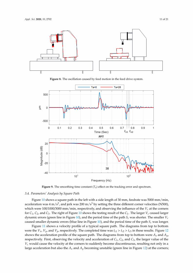
was used to observe the tracking error of each axis, reduce the oscillation of the feed drive systemduring the period of acceleration and deceleration, and avoid the rough surface on the workpiece.The Acc/Dec is equivalent to an impact on the input of the mechanism. If the bandwidth of the impactis greater than the resonance mode of the machine, the resonance is easily excited. Generally, thecontroller smoothed the oscillation during acceleration and deceleration by the filter for the timeconstant parameter. The function of the filter was to ensure smooth path velocity but it increased thecompletion time of the machining and the dynamic errors of the path. Figure 9 shows the experimentalresults of a straight path whose distance was 25 mm, acceleration was 10 m/s2, and feedrate was6000 mm/min with different filter Ta (N400). Figure 9 shows the tracking error for a single axis,and it also shows the spectrum of the fast Fourier transformation (FFT) based on the tracking error.The spectrum can be observed that there were two peaks caused by the oscillation of the feed drivesystem. Their resonance frequencies were 38 and 46 Hz, respectively. The first resonance should havebeen suppressed by the proper Ta. It can be observed that after the Ta was 26 ms, the first resonancewas suppressed. If the Ta was based on the second resonance frequency, then the oscillation still wasexcited for the feed drive system. For the tracking error, it was found that after increasing Ta, theoscillation was reduced after passing of the Acc/Dec (red line in Figure 9). In addition, when theTa was 0, the path completion time was ts1. When the Ta was 26 ms, the path completion time wasextended to ts2. In this case, the Ta was 0 ms for the HS mode, and the Ta was 26 ms for the HQ mode.
Appl. Sci. 2020, 10, x FOR PEER REVIEW 11 of 22
Figure 7. Analysis of straight path with different parameters.
Figure 8. The oscillation caused by feed motion in the feed drive system.
Figure 7. Analysis of straight path with different parameters.
Appl. Sci. 2020, 10, 2702 11 of 21
Appl. Sci. 2020, 10, x FOR PEER REVIEW 11 of 22
Figure 7. Analysis of straight path with different parameters.
Figure 8. The oscillation caused by feed motion in the feed drive system. Figure 8. The oscillation caused by feed motion in the feed drive system.
Appl. Sci. 2020, 10, x FOR PEER REVIEW 12 of 22
Figure 9. The smoothing time constant (𝑇 ) effect on the tracking error and spectrum
3.4. Parameters’ Analysis by Square Path
Figure 10 shows a square path in the left with a side length of 30 𝑚𝑚 , feedrate was 5000 𝑚𝑚 𝑚𝑖𝑛⁄ , acceleration was 4 𝑚 𝑠⁄ , and jerk was 200 𝑚 𝑠⁄ by setting the three different corner velocities (N500), which were 100/1000/3000 𝑚𝑚 𝑚𝑖𝑛⁄ , respectively, and observing the influence of the 𝑉 at the corners for 𝐶 , 𝐶 , and 𝐶 . The right of Figure 10 shows the testing result of the 𝐶 . The larger 𝑉 caused larger dynamic errors (green line in Figure 10), and the period time of the path 𝑆 was shorter. The smaller 𝑉 caused smaller dynamic errors (blue line in Figure 10), and the period time of the path 𝑆 was longer.
Error! Reference source not found. shows a velocity profile of a typical square path. The diagrams from top to bottom were the 𝑉 , 𝑉 , and 𝑉 , respectively. The completed time was 𝑡 >𝑡 >𝑡 in these results. Figure 11 shows the acceleration profile of the square path. The diagrams from top to bottom were 𝐴 and 𝐴 , respectively. First, observing the velocity and acceleration of 𝐶 , 𝐶 , and 𝐶 , the larger value of the 𝑉 would cause the velocity at the corners to suddenly become discontinuous, resulting not only in a large acceleration but also the 𝐴 and 𝐴 becoming unstable (green line in Figure 11) at the corners; oscillation would occur in the constant velocity section. The smaller 𝑉 would cause smooth velocity because the 𝐴 and 𝐴 reached the set value of the parameter at the corner. The performance of the HP mode included the dimensional accuracy and geometric accuracy of the workpiece, which means the dynamic errors needed to be smallest when the path was performed. In this case, the 𝑉 was 3000 𝑚𝑚 𝑚𝑖𝑛⁄ for the HS mode, and the 𝑉 was 100 𝑚𝑚 𝑚𝑖𝑛⁄ for the HP mode. However, if the 𝑉 is largest, the completion time is shortest for the path, but the dynamic errors will increase on the corner at the same time.
Figure 9. The smoothing time constant (Ta) effect on the tracking error and spectrum.
3.4. Parameters’ Analysis by Square Path
Figure 10 shows a square path in the left with a side length of 30 mm, feedrate was 5000 mm/min,acceleration was 4 m/s2, and jerk was 200 m/s3 by setting the three different corner velocities (N500),which were 100/1000/3000 mm/min, respectively, and observing the influence of the Vc at the cornersfor C1, C2, and C3. The right of Figure 10 shows the testing result of the C1. The larger Vc caused largerdynamic errors (green line in Figure 10), and the period time of the path Sc was shorter. The smaller Vc
caused smaller dynamic errors (blue line in Figure 10), and the period time of the path Sc was longer.Figure 11 shows a velocity profile of a typical square path. The diagrams from top to bottom
were the Vx, Vy, and Vp, respectively. The completed time was tc1 > tc2 > tc3 in these results. Figure 12shows the acceleration profile of the square path. The diagrams from top to bottom were Ax and Ay,respectively. First, observing the velocity and acceleration of C1, C2, and C3, the larger value of theVc would cause the velocity at the corners to suddenly become discontinuous, resulting not only in alarge acceleration but also the Ax and Ay becoming unstable (green line in Figure 12) at the corners;

Appl. Sci. 2020, 10, 2702 12 of 21
oscillation would occur in the constant velocity section. The smaller Vc would cause smooth velocitybecause the Ax and Ay reached the set value of the parameter at the corner. The performance of theHP mode included the dimensional accuracy and geometric accuracy of the workpiece, which meansthe dynamic errors needed to be smallest when the path was performed. In this case, the Vc was3000 mm/min for the HS mode, and the Vc was 100 mm/min for the HP mode. However, if the Vc islargest, the completion time is shortest for the path, but the dynamic errors will increase on the cornerat the same time.Appl. Sci. 2020, 10, x FOR PEER REVIEW 13 of 22
Figure 10. The dynamic errors of the square path.
Figure 11. Analysis of square path with different corner velocity (𝑉 ).
Figure 10. The dynamic errors of the square path.
Appl. Sci. 2020, 10, x FOR PEER REVIEW 13 of 22
Figure 10. The dynamic errors of the square path.
Figure 11. Analysis of square path with different corner velocity (𝑉 ). Figure 11. Analysis of square path with different corner velocity (Vc).

Appl. Sci. 2020, 10, 2702 13 of 21Appl. Sci. 2020, 10, x FOR PEER REVIEW 14 of 22
Figure 11. Analysis of the acceleration at each corner with different corner velocity (𝑉 ).
3.5. Parameters’ Analysis by Circular Path
Figure 12 shows the experimental results of a circular path with a radius of 15 𝑚𝑚, acceleration of 4 m 𝑠⁄ , and jerk of 200 m 𝑠⁄ . Adjust the three conditions of different 𝑉 (N600) (blue line: 3000 𝑚𝑚 𝑚𝑖𝑛⁄ ; red line: 6000 𝑚𝑚 𝑚𝑖𝑛⁄ ; green line: 9000 𝑚𝑚 𝑚𝑖𝑛⁄ ) and observe the feedback signals. In order to easily observe the testing results with variant 𝑉 , the feedrate of NC code must be greater than 9000 𝑚𝑚 𝑚𝑖𝑛⁄ ; otherwise, 𝑉 is limited by the feedrate. Figure 13 shows the conversion of a circular path into a straight line. The diagrams from top to bottom show that actual radius value and dynamic errors were due to different 𝑉 , respectively. The horizontal axis in the error graph is the angle, and the black line is the reference path. The four quadrants of the circular path, 𝐴 , 𝐴 , 𝐴 , and 𝐴 , were the reverse directions of the axis, at the position of the axis where acceleration and deceleration occur. The acceleration value was limited by parameters including N101~103, N201~203, and N301~303. The sharp corners caused the backlash of the feed drive system, and the sharp corners’ error value reduced the dynamic errors, so that the influence of 𝐴 , 𝐴 , 𝐴 , and 𝐴 should not be estimated in the dynamic errors. To analyze the influence of 𝑉 on the circular path, a large 𝑉 will produce large dynamic errors, and a smaller 𝑉 will produce smaller dynamic errors.
Figure 14 shows the velocity curve for a typical circular path. The diagrams from top to bottom present 𝑉 , 𝑉 , and 𝑉 . The 𝑉 and 𝑉 are sine waves, and 𝑉 had a constant velocity except at the start position and the end position. Comparing the completion time of the path, the result was 𝑡 >𝑡 >𝑡 . In this case, the 𝑉 was 9000 𝑚𝑚 𝑚𝑖𝑛⁄ for the HS mode, and the 𝑉 was 3000 𝑚𝑚 𝑚𝑖𝑛⁄ for the HP mode. However, if the 𝑉 is largest, the completion time is shortest for the path, and the dynamic errors increase at the same time.
In summary, in order to reduce the dynamic errors, the jerk, acceleration, 𝑉 , and 𝑉 need to be reduced properly, so that the advantage of HP mode is fewer dynamic errors, but the path completion time becomes longer. In general, HP mode is used for the finishing process, and most machining requirements are dimensional accuracy and geometric accuracy. However, mold processing needs more dimensional accuracy requirement, not geometric accuracy.
Figure 12. Analysis of the acceleration at each corner with different corner velocity (Vc).
3.5. Parameters’ Analysis by Circular Path
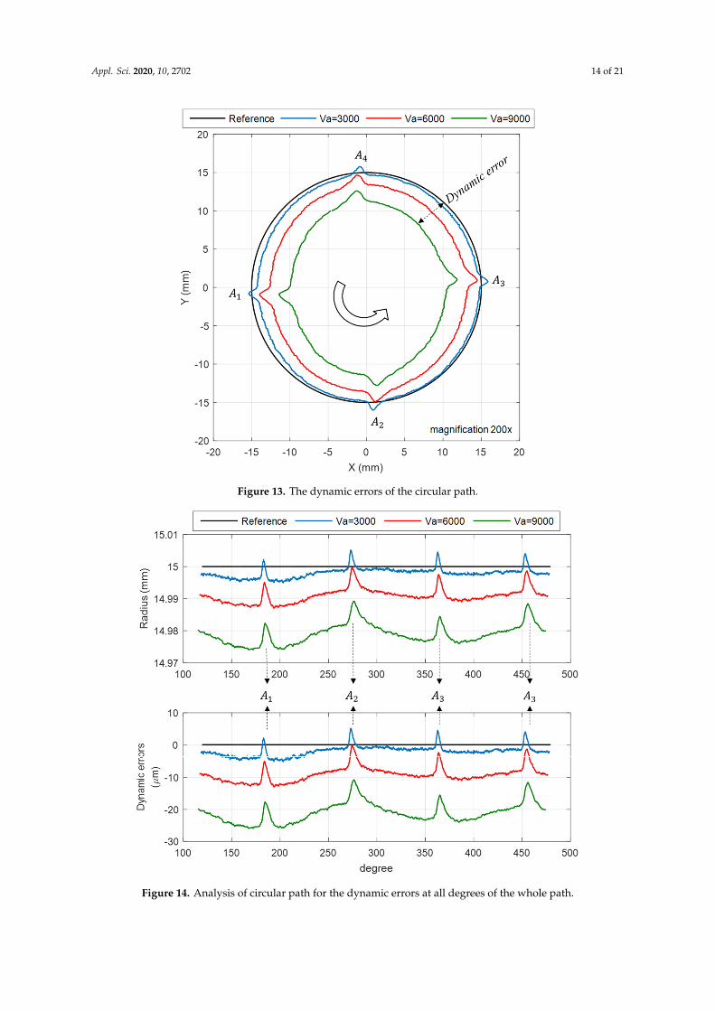
Figure 13 shows the experimental results of a circular path with a radius of 15 mm, accelerationof 4 m/s2, and jerk of 200 m/s3. Adjust the three conditions of different Va (N600) (blue line:3000 mm/min; red line: 6000 mm/min; green line: 9000 mm/min) and observe the feedback signals.In order to easily observe the testing results with variant Va, the feedrate of NC code must be greaterthan 9000 mm/min; otherwise, Va is limited by the feedrate. Figure 14 shows the conversion of acircular path into a straight line. The diagrams from top to bottom show that actual radius valueand dynamic errors were due to different Va, respectively. The horizontal axis in the error graph isthe angle, and the black line is the reference path. The four quadrants of the circular path, A1, A2,A3, and A4, were the reverse directions of the axis, at the position of the axis where acceleration anddeceleration occur. The acceleration value was limited by parameters including N101~103, N201~203,and N301~303. The sharp corners caused the backlash of the feed drive system, and the sharp corners’error value reduced the dynamic errors, so that the influence of A1, A2, A3, and A4 should not beestimated in the dynamic errors. To analyze the influence of Va on the circular path, a large Va willproduce large dynamic errors, and a smaller Va will produce smaller dynamic errors.
Figure 15 shows the velocity curve for a typical circular path. The diagrams from top to bottompresent Vx, Vy, and Vp. The Vx and Vy are sine waves, and Vp had a constant velocity except at thestart position and the end position. Comparing the completion time of the path, the result was ta1 > ta2
> ta3. In this case, the Va was 9000 mm/min for the HS mode, and the Va was 3000 mm/min for theHP mode. However, if the Va is largest, the completion time is shortest for the path, and the dynamicerrors increase at the same time.
Appl. Sci. 2020, 10, 2702 14 of 21Appl. Sci. 2020, 10, x FOR PEER REVIEW 15 of 22
Figure 12. The dynamic errors of the circular path.
Figure 13. Analysis of circular path for the dynamic errors at all degrees of the whole path.
Figure 13. The dynamic errors of the circular path.
Appl. Sci. 2020, 10, x FOR PEER REVIEW 15 of 22
Figure 12. The dynamic errors of the circular path.
Figure 13. Analysis of circular path for the dynamic errors at all degrees of the whole path. Figure 14. Analysis of circular path for the dynamic errors at all degrees of the whole path.

Appl. Sci. 2020, 10, 2702 15 of 21Appl. Sci. 2020, 10, x FOR PEER REVIEW 16 of 22
Figure 14. Analysis of circular path for the velocity of the whole path.
4. Tuning Methodology and Procedure for the CNC Parameters
The relationship between CNC parameters and the three machining modes was verified in Section 3. The experimental results showed the effectiveness of our proposed machining mode for corresponding CNC parameters, which is relevant to the dynamic errors of the machine. The tuning methodology and procedures of the CNC parameters were defined by the simple path, as shown in Figure 15. Firstly, the anticipated dynamic errors were defined as the maximum magnitude of the tool path that had first been allowed. In this paper, the anticipated dynamic errors of the HS/HP/HQ mode were set to 0.05/0.01/0.02 𝑚𝑚, respectively. Actually, the anticipated dynamic errors had no absolute value. They must to be adjusted by the operator for the product requirements. The specified paths used the relevant feedrate for testing. We suggest the proper feedrate that the machining condition used. According to anticipated dynamic errors and the circular test, the 𝐴 and 𝑉 could be easily calculated based on Equation (1), secondly. For the 𝐴 and straight test, the 𝐽 was calculated. The 𝑇 and 𝑉 were estimated based on the square test. The tuning procedure was based on actual measurement of the machine’s two-dimensional contouring performance. The machine’s dynamic errors were measured with simple paths, and the best combination of CNC parameters were chosen. A practical methodology will be discussed in this section in detail.
Figure 15. Analysis of circular path for the velocity of the whole path.
In summary, in order to reduce the dynamic errors, the jerk, acceleration, Vc, and Va need to bereduced properly, so that the advantage of HP mode is fewer dynamic errors, but the path completiontime becomes longer. In general, HP mode is used for the finishing process, and most machiningrequirements are dimensional accuracy and geometric accuracy. However, mold processing needsmore dimensional accuracy requirement, not geometric accuracy.
4. Tuning Methodology and Procedure for the CNC Parameters
The relationship between CNC parameters and the three machining modes was verified inSection 3. The experimental results showed the effectiveness of our proposed machining mode forcorresponding CNC parameters, which is relevant to the dynamic errors of the machine. The tuningmethodology and procedures of the CNC parameters were defined by the simple path, as shown inFigure 16. Firstly, the anticipated dynamic errors were defined as the maximum magnitude of the toolpath that had first been allowed. In this paper, the anticipated dynamic errors of the HS/HP/HQ modewere set to 0.05/0.01/0.02 mm, respectively. Actually, the anticipated dynamic errors had no absolutevalue. They must to be adjusted by the operator for the product requirements. The specified paths usedthe relevant feedrate for testing. We suggest the proper feedrate that the machining condition used.According to anticipated dynamic errors and the circular test, the Ap and Va could be easily calculatedbased on Equation (1), secondly. For the Ap and straight test, the Jp was calculated. The Ta and Vc wereestimated based on the square test. The tuning procedure was based on actual measurement of themachine’s two-dimensional contouring performance. The machine’s dynamic errors were measuredwith simple paths, and the best combination of CNC parameters were chosen. A practical methodologywill be discussed in this section in detail.

Appl. Sci. 2020, 10, 2702 16 of 21
Appl. Sci. 2020, 10, x FOR PEER REVIEW 17 of 22
Figure 15. CNC parameter tuning methodology and procedure.
4.1. Allowable Acceleration
The acceleration of any axis results from the force caused by the feed drive system, and leads to contour error on the components. This means that by measuring dynamic errors and correlating them to effective acceleration, maximum allowable acceleration values for each axis can be set depending on the anticipated path accuracy. According to the circular testing, the dynamic errors can be evaluated due to the limited circle radius 𝑅 . With small circles and increasing 𝑉 , the required acceleration values 𝐴 become very high (Equation (1)). Examples can be seen in Figure 12 and Figure 13. According to Newton’s second law and Hooke’s law expressed as: 𝐹 = 𝑚𝑎 = 𝑘𝛥𝑥 (5)
where 𝑚 and 𝑘 are equivalent mass and equivalent stiffness, which are assumed the constants for the closed loop feed drive system in this paper, they are usually hard to tune by the machine operator. The 𝑎 and 𝛥𝑥 are acceleration and deformation of system. According to Equation (5), we can easily understand the relationship between acceleration and dynamic errors. Finally, the equation of acceleration and dynamic errors was obtained by the linear regression method expressed as: 𝐴 = 𝐴 = 63.551 𝜀 0.1543 (6)
where 𝐴 is allowable acceleration for path movement, 𝐴 is allowable acceleration for axis movement, and 𝜀 is anticipated dynamic errors. According to Equation (6), the allowable acceleration has limits of HS/HP/HQ modes: 3.02/0.48/1.12 𝑚 𝑠⁄ , respectively. Therefore, these tests are useful for verifying the allowable acceleration value. This means that the CNC parameters related to acceleration can be evaluated. When the NC code was a circular path, the N600 of CNC parameters will be defined by the radius of curvature and Equation (1). In this paper, the radius of curvature of the commercial controller was 5 𝑚𝑚, and the arc velocities in HS/HP/HQ mode were 7373/2939/4490 𝑚𝑚 𝑚𝑖𝑛,⁄ respectively.
Figure 16. CNC parameter tuning methodology and procedure.
4.1. Allowable Acceleration
The acceleration of any axis results from the force caused by the feed drive system, and leads tocontour error on the components. This means that by measuring dynamic errors and correlating themto effective acceleration, maximum allowable acceleration values for each axis can be set depending onthe anticipated path accuracy. According to the circular testing, the dynamic errors can be evaluateddue to the limited circle radius R. With small circles and increasing Va, the required accelerationvalues Aa become very high (Equation (1)). Examples can be seen in Figures 13 and 14. According toNewton’s second law and Hooke’s law expressed as:
F = ma = k∆x (5)
where m and k are equivalent mass and equivalent stiffness, which are assumed the constants for theclosed loop feed drive system in this paper, they are usually hard to tune by the machine operator. The aand ∆x are acceleration and deformation of system. According to Equation (5), we can easily understandthe relationship between acceleration and dynamic errors. Finally, the equation of acceleration anddynamic errors was obtained by the linear regression method expressed as:
Ap = Aa = 63.551× ε3 − 0.1543 (6)
where Ap is allowable acceleration for path movement, Aa is allowable acceleration for axis movement,and ε3 is anticipated dynamic errors. According to Equation (6), the allowable acceleration has limitsof HS/HP/HQ modes: 3.02/0.48/1.12 m/s2, respectively. Therefore, these tests are useful for verifyingthe allowable acceleration value. This means that the CNC parameters related to acceleration can beevaluated. When the NC code was a circular path, the N600 of CNC parameters will be defined by theradius of curvature and Equation (1). In this paper, the radius of curvature of the commercial controllerwas 5 mm, and the arc velocities in HS/HP/HQ mode were 7373/2939/4490 mm/min, respectively.
Appl. Sci. 2020, 10, 2702 17 of 21
4.2. Allowable Jerk
The jerk profiles were similar to the impact force on the mechanical structure. The jerk is a dynamicexcitation of the machine, which will cause oscillation in its structure resonance, meaning relativedisplacements between tool and workpiece, as illustrated in Figure 8. The oscillating characteristicis created by the driving torque or force. This means the measured tracking error of the relevantresonance frequencies can be identified with FFT. For this reason, the allowable jerk values for each axiscan be identified at the same time. According to the straight path testing, the mechanical resonance canbe identified with tracking error, as illustrated in Figure 9 (blue line). The first resonance of machinewas about 38 Hz. The allowable jerk (Jp) can be evaluated due to the time constant of Acc/Dec (Tp)and allowable acceleration (Ap) (maximum value Jp = Ap/Tp). The allowable acceleration was set inSection 4.1, and the allowable jerk limits of HS/HP/HQ mode were 114.88/18.29/42.44 m/s3, respectively.It means that the CNC parameters related to jerk can be evaluated.
4.3. Smoothing Time Constant
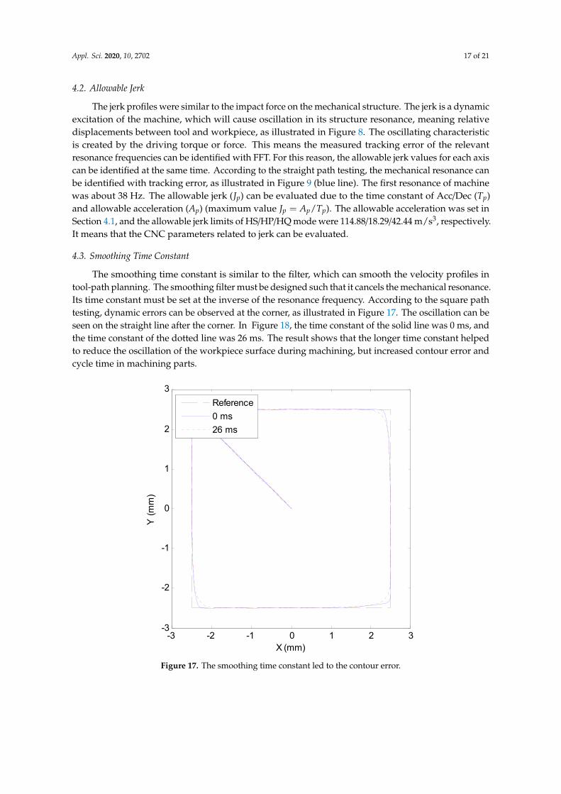
The smoothing time constant is similar to the filter, which can smooth the velocity profiles intool-path planning. The smoothing filter must be designed such that it cancels the mechanical resonance.Its time constant must be set at the inverse of the resonance frequency. According to the square pathtesting, dynamic errors can be observed at the corner, as illustrated in Figure 17. The oscillation can beseen on the straight line after the corner. In Figure 18, the time constant of the solid line was 0 ms, andthe time constant of the dotted line was 26 ms. The result shows that the longer time constant helpedto reduce the oscillation of the workpiece surface during machining, but increased contour error andcycle time in machining parts.
Appl. Sci. 2020, 10, x FOR PEER REVIEW 18 of 22
4.2. Allowable Jerk
The jerk profiles were similar to the impact force on the mechanical structure. The jerk is a dynamic excitation of the machine, which will cause oscillation in its structure resonance, meaning relative displacements between tool and workpiece, as illustrated in Figure 8. The oscillating characteristic is created by the driving torque or force. This means the measured tracking error of the relevant resonance frequencies can be identified with FFT. For this reason, the allowable jerk values for each axis can be identified at the same time. According to the straight path testing, the mechanical resonance can be identified with tracking error, as illustrated in Figure 9 (blue line). The first resonance of machine was about 38 𝐻𝑧. The allowable jerk (𝐽 ) can be evaluated due to the time constant of Acc/Dec (𝑇 ) and allowable acceleration (𝐴 ) (maximum value 𝐽 = 𝐴 𝑇⁄ ). The allowable acceleration was set in Section 4.1, and the allowable jerk limits of HS/HP/HQ mode were 114.88/18.29/42.44 𝑚 𝑠 ,⁄ respectively. It means that the CNC parameters related to jerk can be evaluated.
4.3. Smoothing Time Constant
The smoothing time constant is similar to the filter, which can smooth the velocity profiles in tool-path planning. The smoothing filter must be designed such that it cancels the mechanical resonance. Its time constant must be set at the inverse of the resonance frequency. According to the square path testing, dynamic errors can be observed at the corner, as illustrated in Figure 16. The oscillation can be seen on the straight line after the corner. In Figure 17, the time constant of the solid line was 0 𝑚𝑠, and the time constant of the dotted line was 26 𝑚𝑠. The result shows that the longer time constant helped to reduce the oscillation of the workpiece surface during machining, but increased contour error and cycle time in machining parts.
Figure 16. The smoothing time constant led to the contour error.
-3 -2 -1 0 1 2 3-3
-2
-1
0
1
2
3
X (mm)
Y (m
m)
Reference0 ms26 ms
Figure 17. The smoothing time constant led to the contour error.

Appl. Sci. 2020, 10, 2702 18 of 21Appl. Sci. 2020, 10, x FOR PEER REVIEW 19 of 22
Figure 17. The smoothing time constant led to the oscillation of the tool path.
4.4. Corner Velocity
A higher corner velocity is useful for shorter cycle time, but it would cause larger dynamic errors (or corner error). If it is too high, it easily causes structural vibration at the corners. The vibration could be decreased by the smoothing time constant, but the errors would be increased at the corners. The corner velocity is proportional to the corner error. However, the corner error also includes the effect of the tracking error from the servo loop. However, while there is a lot of domain knowledge to tune the tracking error, it is not easy for the machine operator to use. Therefore, this paper regarded the servo loop as a black box. We proposed the experimental methods to create the relationship between the corner velocity and corner error. According to the experimental results of Section 3.4 for square path testing, the dynamic errors can be observed at the corner. We fed the different jerk, acceleration, 𝑉 , and feedrate for the square path, respectively, summarized as follows:
• The larger jerk and acceleration will increase the corner error as the feedrate increases. • There are two sets of parameters: One is 𝐽 = 100 m s⁄ and 𝐴 = 2.5 m s⁄ , and the other one
is 𝐽 = 50 m s⁄ , 𝐴 = 1.2 m s⁄ . The corner errors are more stable than the other set of parameters for the different feedrates.
• If the 𝑉 is set to 3000 mm min⁄ , when the feedrate exceeds 3000 mm min⁄ , the corner errors are more stable. This is caused by the current feedrate being lower than the anticipated 𝑉 . The 𝑉 will give priority to the current feedrate for tool-path planning.
The experimental data on the square path were used to estimate the maximum corner errors of each measurement result. The jerk, acceleration, 𝑉 , and feedrate by the test conditions were considered as inputs, and the corner errors as outputs. Multiple regression analysis was used to obtain the regression formula for the inputs and outputs. Finally, the maximum corner error was set to the dynamic errors of the HS/HP/HQ modes expected in this paper. The feedrate was 4000 mm/min for the square path, the allowable acceleration, and allowable jerk, in Sections 4.1 and 4.2, as the inputs of the regression formula, and solving the allowable 𝑉 of the HS/HP/HQ modes. The corresponding 𝑉 were 1470/250/550 𝑚𝑚 𝑚𝑖𝑛⁄ , respectively.
5. Experimental Validation
In Section 3, the experimental results showed the effectiveness of our proposed machining modes for corresponding CNC parameters, which is relevant to the dynamic errors of the machine. According to the tuning methodology and procedures of the CNC parameters implemented, the relevant CNC parameters were estimated based on the anticipated dynamic errors in Section 4. This section proposed a single square path with the same 4000 𝑚𝑚/𝑚𝑖𝑛 feedrate and the length was 30 𝑚𝑚 to verify the validation of the tuning methodology. We used the three sets of CNC parameters
-2 0 2
-2.5
-2.49
-2.48
-2.47
-2.46
-2.45
X (mm)
Y (m
m)
2.46 2.48 2.5-3
-2
-1
0
1
2
3
X (mm)
Figure 18. The smoothing time constant led to the oscillation of the tool path.
4.4. Corner Velocity
A higher corner velocity is useful for shorter cycle time, but it would cause larger dynamic errors(or corner error). If it is too high, it easily causes structural vibration at the corners. The vibrationcould be decreased by the smoothing time constant, but the errors would be increased at the corners.The corner velocity is proportional to the corner error. However, the corner error also includes theeffect of the tracking error from the servo loop. However, while there is a lot of domain knowledge totune the tracking error, it is not easy for the machine operator to use. Therefore, this paper regarded theservo loop as a black box. We proposed the experimental methods to create the relationship betweenthe corner velocity and corner error. According to the experimental results of Section 3.4 for squarepath testing, the dynamic errors can be observed at the corner. We fed the different jerk, acceleration,Vc, and feedrate for the square path, respectively, summarized as follows:
• The larger jerk and acceleration will increase the corner error as the feedrate increases.• There are two sets of parameters: One is Jp = 100 m/s3 and Ap = 2.5 m/s2, and the other one is
Jp = 50 m/s3, Ap = 1.2 m/s2. The corner errors are more stable than the other set of parametersfor the different feedrates.
• If the Vc is set to 3000 mm/min, when the feedrate exceeds 3000 mm/min, the corner errors aremore stable. This is caused by the current feedrate being lower than the anticipated Vc. The Vc
will give priority to the current feedrate for tool-path planning.
The experimental data on the square path were used to estimate the maximum corner errorsof each measurement result. The jerk, acceleration, Vc, and feedrate by the test conditions wereconsidered as inputs, and the corner errors as outputs. Multiple regression analysis was used to obtainthe regression formula for the inputs and outputs. Finally, the maximum corner error was set to thedynamic errors of the HS/HP/HQ modes expected in this paper. The feedrate was 4000 mm/min for thesquare path, the allowable acceleration, and allowable jerk, in Sections 4.1 and 4.2, as the inputs ofthe regression formula, and solving the allowable Vc of the HS/HP/HQ modes. The corresponding Vc
were 1470/250/550 mm/min, respectively.
5. Experimental Validation
In Section 3, the experimental results showed the effectiveness of our proposed machining modesfor corresponding CNC parameters, which is relevant to the dynamic errors of the machine. Accordingto the tuning methodology and procedures of the CNC parameters implemented, the relevant CNCparameters were estimated based on the anticipated dynamic errors in Section 4. This section proposeda single square path with the same 4000 mm/min feedrate and the length was 30 mm to verifythe validation of the tuning methodology. We used the three sets of CNC parameters (see Table 2)

Appl. Sci. 2020, 10, 2702 19 of 21
corresponding to the “HS, HP, and HQ modes” in the actual machine platform for validation, therebyobserving the performance of the motion dynamic under various modes.
Table 2. CNC parameters for tool-path movement with machining modes.
No. Sym. Description Unit HS HP HQ
N100 Jp Maximum jerk for tool-path movement m/s3 114.88 18.29 42.44N200 Ap Maximum acceleration for tool-path movement m/s2 3.02 0.48 1.12N300 Tp Time constant of Acc/Dec for tool-path movement ms 26 26 26N400 Ta Smoothing time constant for tool-path movement ms 1 1 26N500 Vc Maximum corner velocity for tool-path movement mm/min 1470 250 550N600 Va Maximum arc velocity for tool-path movement mm/min 7373 2939 4490
The experimental results are listed in Table 3. We observed the time of the completion of the toolpath was the fastest for HS mode. In HP mode, the minimum dynamic errors were of the corners.There was small oscillation that was caused by the tracking error after the cornering in HQ mode.According to the experimental results, the servo parameters could be ignored, and the relevant CNCparameters of the tool-path planning could be adjusted, which can affect the completion time, dynamicerrors, and tracking error of the same path.
Table 3. Experimental results for three machining modes.
Description Unit HS HP HQ
Cycle time sec 1.935 2.655 2.064Dynamic errors mm 0.053 0.018 0.026Tracking error mm 0.007 0.003 0.001
The comparison of HS, HP, and HQ modes are listed in Table 4. In the HS mode, the completiontime of the path was fastest than the other modes. However, the dynamic errors and the tracking errorwere increased by 66% and 85%, respectively. In the HP mode, although the completion time of thepath was increased by 37% compared with the HS mode and the tracking error was increased by 28%,the HP mode was closed to the ideal path with highest accuracy. In the HQ mode, the surface qualityof the workpiece was improved by focusing on reducing the machine resonance, although the dynamicerrors were worse than the HP mode. The surface quality improved by 85% compared with the HSmode. However the completion time was only increased by 6% compared with the HS mode.
Table 4. Comparison of three machining modes from the experimental results.
Description HS HP HQ
Cycle time 0% 37% 6%Dynamic errors 66% 0% 16%Tracking error 85% 28% 0%
The experimental results verified the tuning methodology for CNC parameters of Section 4.We found that no single set of CNC parameters was able to simultaneously satisfy all of the threemachining modes: “High speed”, “high accuracy”, and “high surface quality”. Actually, these threemachining modes often contradict each other. For example, we may have the “high productivity”, butwith “low accuracy and poor surface finish.”
6. Conclusions
Since the required product quality affected CNC parameters of the machine tools, the CNCparameters must be selected to vary the machining performance of the tool-path planning, named as

Appl. Sci. 2020, 10, 2702 20 of 21
HS, HP, and HQ modes, respectively. Actually, the manufacturer provided only a single set of CNCparameters for the commercial CNC machine tools. It was not enough for the different machiningrequirements. However, the performance of the servo loop and actual machine was fixed and washard to be tuned, another reason for needing to have quite a domain knowledge to tune the CNCparameters’ requirements. Therefore, the operator of the machine cannot easily process the differentmachining requirements. This paper introduced the relationship of CNC parameters, dynamic errors,and machining modes. The dynamic errors defined the difference of the ideal position for NC codeto the actual position for linear scale in this study. According to the anticipated dynamic errors forthe three machining modes and feed motion testing by several specified paths’ experiment, suchas straight, square, and circular paths in actual machine tools, the HS, HP, and HQ modes can beachieved by properly tuning the CNC parameters via the tuning methodology. The experimentalresults proposed an approach that contained three sets of CNC parameters. The CNC parameters wereselected to be larger values of Jp, Ap, Vc, and Va, the path completion time was shortened, and theprocessing efficiency improved to match the HS mode. However, the corresponding dynamic errorsbecame larger, which sacrificed accuracy and surface quality. On the other hand, the smaller valuesof CNC parameters resulted in larger completion time and smaller tracking error, and the geometricaccuracy was improved to reach the HP mode. The HQ mode dealt with the worse surface quality ofthe product, caused by feed force for the feed motion. When the feed motion experienced oscillationon the corner or circular paths, the exact Ta reduced the impact of feed force during the high Acc/Decperiod. Although the dynamic errors of HQ mode were larger than in the HP mode, the oscillationcould be reduced during the feed motion. If there is larger oscillation occurring in the HS mode, inaddition to the reduction in Jp, Ap, Vc, and Va, it can also use the Ta to decrease the oscillation for thesmooth surface quality of the geometric shape. However, the cycle time became longer, caused by Ta inthe HQ mode. The experimental results were introduced to illustrate the effectiveness of the proposedapproach. The advantage of this paper is that it has developed a tuning methodology and procedure ofthe CNC parameters based on their relevant machining mode required; it can easily be implementedin a commercial CNC controller of the machine tools. The machine user can simply select the bestmachining mode according to the machining requirements.
Author Contributions: B.-F.Y. and J.-S.C. In itiated and developed the concepts related to this research work.B.-F.Y. performed the collected data for the designed experiment and analyzed the data. Both of them discussedthe experimental results and developed the tuning methodology. B.-F.Y. wrote the paper draft under Chen’sguidance. All authors discussed the results and commented on the manuscript. All authors have read and agreedto the published version of the manuscript.
Funding: The authors would like to thank the reviewers for their suggestions. This research was supported byMinistry of Science and Technology, Taiwan grant to MOST-108-2218-E-005-021-“Intelligent multi-axis machinetool technology for machining the advanced materials of the semiconductor and electronics industries”.
Conflicts of Interest: The authors declare no conflict of interest.
References
1. Erkorkmaz, K. High Speed Contouring Control for Machine Tool Drives. Master’s Thesis, The University ofBritish Columbia, Vancouver, BC, Canada, February 1999.
2. Erkorkmaz, K.; Altintas, Y. High speed CNC system design. Part I: Jerk limited trajectory generation andquantic spline interpolation. Int. J. Mach. Tools Manuf. 2001, 41, 1323–1345. [CrossRef]
3. Nam, S.-H.; Yang, M.-Y. A study on a generalized parametric interpolator with real-time jack-limitedacceleration. Comput. Aided Des. 2004, 36, 27–36. [CrossRef]
4. Barre, P.-J.; Bearee, R.; Borne, P.; Dumetz, E. In fluence of a Jerk Controlled Movement Law on VibratoryBehaviour of High-Dynamics Systems. J. In tell. Robot. Syst. 2005, 42, 275–293. [CrossRef]
5. Lin, M.-T.; Tsai, M.-S.; Yau, H.-T. Development of a dynamics-based NURBS interpolator with real-timelook-ahead algorithm. Int. J. Mach. Tools Manuf. 2007, 47, 2246–2262. [CrossRef]
6. Yau, H.-T.; Wang, J.-B. Fast Bazier interpolator with real-time lookahead function for high-accuracy machining.Int. J. Mach. Tools Manuf. 2007, 47, 1518–1529. [CrossRef]

Appl. Sci. 2020, 10, 2702 21 of 21
7. Sencer, B.; Altintas, Y.; Croft, E. Feed optimization for five-axis CNC machine tools with drive constraints.Int. J. Mach. Tools Manuf. 2008, 48, 733–745. [CrossRef]
8. Tapie, L.; Mawussi, K.B.; Anselmetti, B. Circular tests for HSM machine tools: Bore machining application.Int. J. Mach. Tools Manuf. 2007, 47, 805–819. [CrossRef]
9. Pateloup, V.; Duc, E.; Ray, P. Corner optimization for pocket machining. Int. J. Mach. Tools Manuf. 2004, 44,1343–1353. [CrossRef]
10. Andolfatto, L.; Lavernhe, S.; Mayer, J.R.R. Evaluation of servo, geometric and dynamic error sources onfive-axis high-speed machine tool. Int. J. Mach. Tools Manuf. 2011, 51, 787–796. [CrossRef]
11. Lee, K.; Ibaraki, S.; Matsubara, A.; Kakino, Y.; Suzuki, Y.; Arai, S.; Braasch, J. A Servo Parameter TuningMethod for High-Speed NC Machine Tools based on Contouring Error Measurement. In Laser Metrology andMachine Performance VI; WIT Press: Southampton, UK, 2002.
12. Parenti, P.; Bianchi, G.; Cau, N.; Albertelli, P.; Monno, M. A Mechatronic Study on a Model-BasedCompensation of Inertial Vibration in a High-Speed Machine Tool. J. Mach. Eng. 2011, 11, 91–104.
13. Bringmann, B.; Maglie, P. A method for direct evaluation of the dynamic 3D path accuracy of NC machinetools. CIRP Ann. 2009, 58, 343–346. [CrossRef]
14. Li, B.; Luo, B.; Mao, X.; Cai, H.; Peng, F.; Liu, H. A new approach to identifying the dynamic behaviour ofCNC machine tools with respect to different worktable feed speeds. Int. J. Mach. Tools Manuf. 2013, 72, 73–84.[CrossRef]
15. Franco, P.; Estrems, M.; Faura, F. In fluence of radial and axial runouts on surface roughness in face millingwith round insert cutting tools. Int. J. Mach. Tools Manuf. 2004, 44, 1555–1565. [CrossRef]
16. Buj-Corral, P.; Vivancos-Calvet, V.; González-Rojas, H. Roughness variation caused by grinding errors ofcutting edges in side milling. Mach. Sci. Technol. 2013, 17, 575–592. [CrossRef]
17. Vivancos-Calvet, S.; Wiackiewicz, M.; Krolczyk, G.M. Study on metrological relations between instant tooldisplacements and surface roughness during precise ball end milling. Measurement 2018, 129, 686–694.
18. Mia, M.; Królczyk, G.; Maruda, R.; Wojciechowski, S. In telligent Optimization of Hard-Turning ParametersUsing Evolutionary Algorithms for Smart Manufacturing. Materials 2019, 12, 879. [CrossRef]
19. Li, K.-Y.; Luo, W.-J.; Yang, M.-H.; Hong, X.-H.; Luo, S.-J.; Chen, C.-H. Effect of Supply Cooling Oil Temperaturein Structural Cooling Channels on the Positioning Accuracy of Machine Tools. J. Mech. 2019, 35, 887–900.[CrossRef]
20. Li, K.-Y.; Luo, W.-J.; Huang, J.-Z.; Chan, Y.-C.; Pratikto; Faridah, D. Operational Temperature Effect onPositioning Accuracy of a Single-Axial Moving Carrier. Appl. Sci. 2017, 7, 420. [CrossRef]
21. Altintas, Y.; Verl, A.; Brecher, C.; Uriarte, L.; Pritschow, G. Machine tool feed drives. CIRP Ann. 2011, 60,779–796. [CrossRef]
22. Altintas, Y. Virtual Machine Tool. CIRP Ann. 2005, 54, 115–138. [CrossRef]23. Erkorkmaz, K.; Altintas, Y.; Yeung, C.-H. Virtual computer numerical control system. CIRP Ann. 2006, 55,
399–402. [CrossRef]24. Lin, C.-Y.; Lee, C.-H. Remote Servo Tuning System for Multi-Axis CNC Machine Tools Using a Virtual
Machine Tool Approach. Appl. Sci. 2017, 7, 776. [CrossRef]25. Christian, B.; Fey, M.; Baumler, S. Damping models for machine tool components of linear axes. CIRP Ann.
Manuf. Technol. 2013, 62, 399–402.26. Zaeh, M.F.; Baudisch, T. Simulation environment for designing the dynamic motion behaviour of the
mechatronic system machine tool. Proc. In st. Mech. Eng. Part B J. Eng. Manuf. 2003, 217, 1031–1035.[CrossRef]
27. Heidenhain. Technical Manual iTNC530 HSCI; Heidenhain: Traunreut, Germany, 2011.28. Siemens. SINUMERIK 840D sl Basic Functions–Function Manual. Siemens AG, Germany. 2013.
Available online: https://support.industry.siemens.com/cs/document/109763231/sinumerik-840d-sl-basic-functions?dti=0&lc=en-WW (accessed on 13 April 2020).
© 2020 by the authors. Licensee MDPI, Basel, Switzerland. This article is an open accessarticle distributed under the terms and conditions of the Creative Commons Attribution(CC BY) license (http://creativecommons.org/licenses/by/4.0/).