development of an enhanced ceiling fan: an...
TRANSCRIPT

Development of an Enhanced Ceiling Fan: An Engineering Design Case Study Highlighting
Health, Safety and the Environment
Prepared by:
Marc A. Rosen, Ph.D., P.Eng. Professor
Faculty of Engineering and Applied Science University of Ontario Institute of Technology
2000 Simcoe Street North, Oshawa, Ontario, L1H 7K4, Canada Email: [email protected]
Tel: 905/721-8668
Prepared for:
Minerva Canada http://www.safetymanagementeducation.com
January 2009

Minerva Canada Case Study on Development of an Enhanced Ceiling Fan
Preface This case study describes the development of an enhanced ceiling fan, detailing the engineering design process and highlighting where appropriate health, safety and environmental considerations. The purpose of the case study is to provide an aid to instructors for teaching engineering students and others the importance of a holistic approach to engineering design, and to illustrate how health and safety as well as concerns for environmental impact factor into engineering design. The approach taken in developing this case study included a review of background information, including project reports, documentation on performance data, health and safety codes and standards, and other relevant sources. Discussions were also carried out with key personnel. A ceiling fan design was selected for this case study because it is a typical real product of engineering design, is applicable to many engineering disciplines, and addresses the topical areas of improved energy efficiency and environmental performance. Questions are provided to promote further thought and discussion, and to encourage the reader to expand on the ideas presented in this case study and to consider other applications. Such activities complement the use of the case study in the classroom. This case study is designed for engineering professors and students, but is also suitable for others, e.g., students in related and complementary disciplines such as business and environmental studies, as well as practicing engineers and technologists, managers and senior executives. The case study is particularly suited for courses with significant coverage of engineering design. The author invites feedback and comments from interested parties and users, so that the case study can be enhanced in the future.
2

Minerva Canada Case Study on Development of an Enhanced Ceiling Fan
Acknowledgements The author acknowledges the many reports by the developers of the enhanced ceiling fan and the articles written by others about the design of this product, all of which were drawn on extensively in the preparation of this case study. These sources are listed in the references. Special thanks are due to Danny S. Parker, Principal Research Scientist, Buildings Research, Florida Solar Energy Center, for the assistance he provided in the preparation of this case study by providing information, providing permission to use figures from the project report [1] and reviewing. Finally, thanks are offered to Minerva Canada for its dedication to improved education in health and safety in engineering and business through many initiatives, including support of this case study. The comments and suggestions provided during the development of this case study by Minerva Canada’s Board of Directors and its Working Committee are gratefully acknowledged.
3

Minerva Canada Case Study on Development of an Enhanced Ceiling Fan
1. Introduction Concerns related to energy and the environment are prevalent today. Such concerns sometimes become opportunities in that they lead to new inventions and innovations, often developed through engineering design. In this case study, the engineering design of a particular new product is described, which addresses both energy and environmental concerns by increasing the efficiency with which energy resources are utilized in buildings. Increased efficiency permits reduced use of energy resources and emissions of wastes. The new product considered here is an enhanced ceiling fan. Conventional ceiling fans have the potential to increase energy efficiency, but the enhancements described in this case study increase the device’s efficiency further, thereby permitting greater gains. The focus of this case study is on modifying the blade design. This case study focuses on an enhanced ceiling fan for residential buildings, but extensions to versions applicable in industrial and commercial settings are also discussed. The case study outlines the development of the enhanced ceiling fan and describes the engineering design steps followed. Additionally, the non-technical design factors considered, which affected the resulting design, are outlined. These include business forces, customer expectations, manufacturing, reliability, economics, marketability and aesthetics. Health and safety issues and environmental ramifications are highlighted where relevant, showing how they integrate into the overall engineering design process. Finally, a description is provided of the final product and its commercial success. Given the number of factors to be considered, a concurrent engineering design approach is used, in which multiple design issues are addressed simultaneously. The design process is divided into three main sections: • preliminary technical design, where initial concepts are investigated and a basic design
evolves, • secondary technical design, where other critical issues like health and safety, environment,
efficiency, and codes and standards are considered and the design is modified correspondingly, and
• consideration of other design factors like liability, human factors, aesthetics, customer expectations and marketability, manufacturing and materials, controls and economics, and finalization of the design.
Much of the material presented in this case study is drawn from the main technical report on the development of the ceiling fan [1] and the ensuing patent [2], as well as several media reports on the enhanced ceiling fan [3-5] and personal communications with one of the principal developers [6]. It is noted that many good general references exist on product design [7] and engineering design [8-10], so these topics are not reviewed extensively here. Further, some design activities have
4

Minerva Canada Case Study on Development of an Enhanced Ceiling Fan
been reported directly involving ceiling fans [11-13] and indirectly considering ceiling fans in the larger context of building design [14-16]. 2. Preliminary Technical Design 2.1. Concept Definition Danny Parker, a principal research scientist at the Florida Solar Energy Center, noticed in the 1990s that the ceiling fans then had a common feature: flat blades. Such blades clearly had the advantage of simplicity, but Parker, who had investigated ceiling fans [17-18], questioned whether the efficiency of ceiling fans could be improved if the blades were more aerodynamic. This simple questioning led to an extensive engineering design process to create a more efficient residential ceiling fan, primarily through the use of aerodynamically designed fan blades [1]. 2.2. Preliminary Component Design A typical ceiling fan has only a few primary components: a motor, fan blades and, sometimes, a light. The focus of the development was to modify the fan blades to make the fan more aerodynamic and consequently more efficient. But it was recognized that modifications to the fan blades may impact the design of other components, and that efficiency gains may be attained by paying careful attention to them. Some specific details relating to the preliminary design of components follow. Note that these preliminary ideas were modified and refined as the design process progressed and additional factors were taken into account. • A motor is needed to drive the fan, and it was understood that the use of high-efficiency
motors provided one means of increasing ceiling-fan efficiency. • Most ceiling fans incorporate lights, likely because ceiling fans are usually positioned
centrally in a room, which is often a convenient and effective location for a light. Thus the option to include a light in the fan design was considered.
• Aerodynamic blades were felt to provide an opportunity to increase efficiency, by allowing a less expensive, lower-power motor to replace the larger motors on conventional ceiling fans, to move the same air volume.
A flat blade has two major drawbacks: a nearly even chord length over its entire span and a fixed pitch angle. Because the tip of a blade moves at a higher rotational speed than its root, air flow over a conventional fan blade is lowest near the hub and highest at the tip. Smoothing this distribution would allow the entire blade to contribute equally to moving air. A standard for ceiling fans of Underwriters Laboratories Inc. (UL), a product safety testing organization [19], limits the blade rotational speed to between 50 and 200 rpm [20], so the blade design had to accommodate that requirement. Parker said that that requirement presented a challenge, because propellers normally spin much faster. Aerodynamics experts are used to
5
Minerva Canada Case Study on Development of an Enhanced Ceiling Fan
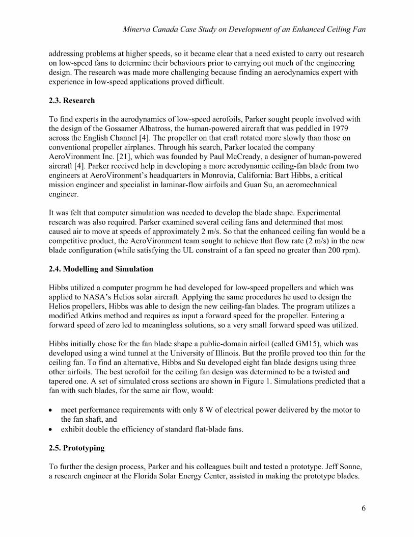
addressing problems at higher speeds, so it became clear that a need existed to carry out research on low-speed fans to determine their behaviours prior to carrying out much of the engineering design. The research was made more challenging because finding an aerodynamics expert with experience in low-speed applications proved difficult. 2.3. Research To find experts in the aerodynamics of low-speed aerofoils, Parker sought people involved with the design of the Gossamer Albatross, the human-powered aircraft that was peddled in 1979 across the English Channel [4]. The propeller on that craft rotated more slowly than those on conventional propeller airplanes. Through his search, Parker located the company AeroVironment Inc. [21], which was founded by Paul McCready, a designer of human-powered aircraft [4]. Parker received help in developing a more aerodynamic ceiling-fan blade from two engineers at AeroVironment’s headquarters in Monrovia, California: Bart Hibbs, a critical mission engineer and specialist in laminar-flow airfoils and Guan Su, an aeromechanical engineer. It was felt that computer simulation was needed to develop the blade shape. Experimental research was also required. Parker examined several ceiling fans and determined that most caused air to move at speeds of approximately 2 m/s. So that the enhanced ceiling fan would be a competitive product, the AeroVironment team sought to achieve that flow rate (2 m/s) in the new blade configuration (while satisfying the UL constraint of a fan speed no greater than 200 rpm). 2.4. Modelling and Simulation Hibbs utilized a computer program he had developed for low-speed propellers and which was applied to NASA’s Helios solar aircraft. Applying the same procedures he used to design the Helios propellers, Hibbs was able to design the new ceiling-fan blades. The program utilizes a modified Atkins method and requires as input a forward speed for the propeller. Entering a forward speed of zero led to meaningless solutions, so a very small forward speed was utilized. Hibbs initially chose for the fan blade shape a public-domain airfoil (called GM15), which was developed using a wind tunnel at the University of Illinois. But the profile proved too thin for the ceiling fan. To find an alternative, Hibbs and Su developed eight fan blade designs using three other airfoils. The best aerofoil for the ceiling fan design was determined to be a twisted and tapered one. A set of simulated cross sections are shown in Figure 1. Simulations predicted that a fan with such blades, for the same air flow, would: • meet performance requirements with only 8 W of electrical power delivered by the motor to
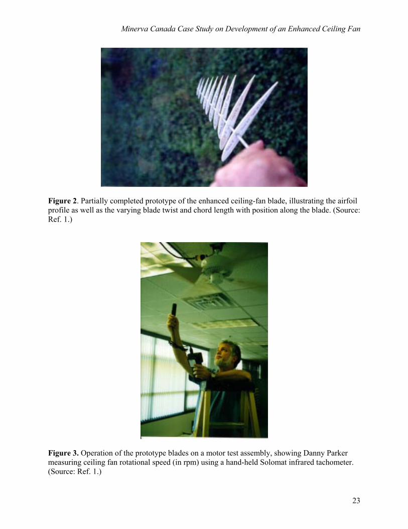
the fan shaft, and • exhibit double the efficiency of standard flat-blade fans. 2.5. Prototyping To further the design process, Parker and his colleagues built and tested a prototype. Jeff Sonne, a research engineer at the Florida Solar Energy Center, assisted in making the prototype blades.
6

Minerva Canada Case Study on Development of an Enhanced Ceiling Fan
The first prototypes were constructed by laying fiberglass over wooden cores, but this process proved unsuccessful. This challenge illustrates the importance of constructability, which is one of many factors to be considered in engineering design. Others include operability, maintainability, disposability, etc. Sonne switched to a different construction method, involving construction by hand with a combination of metal spars, wooden struts and profiles, and balsa skins. With this labour-intensive method, he built four blades. To construct a blade, Sonne cut numerous profiles from balsa sheet. He then attached them to a thin metal tube every five centimeters, using rapid-set instant glue. He tilted each profile to match the profiles predicted by the simulations. A partially constructed prototype is shown in Figure 2. Small balsa blocks were glued between adjacent profiles to stiffen the airfoil while an epoxy coating was added to the instant glue to strengthen the bond at each joint. Finally, the blades were covered with several balsa sheets of 0.4 mm (1/64 inch) thickness. 2.6. Prototype Testing A test lab was created with necessary instrumentation at the Florida Solar Energy Center in 1997 and used by Parker and his colleagues to compare the performance of the prototype airfoils with that of flat blades on three common commercial fans (see Figure 3). The performance characteristics and the measuring devices for them were as follows: • air flow rate, which was measured with a hot-wire anemometer, • power use, which was measured with a digital watt-hour meter, and • fan shaft rotational speed, which was measured with an infrared tachometer. Air flow was examined for all the fans at several locations. Specifically, 12 measurements were taken starting at the axial center and then at intervals of 15 cm (6 inches) outward from the center. As the radii of all fans did not exceed 66 cm (26 inches), about half of the measurements were below the fan blades. The other measurements were beyond the reach of any fan and were taken to identify how far outside the sweep of a fan the flowing air extended. For four fans at high speed operation, Table 1 shows the measured air flow rate over the 1.8 m (6 ft) region comprising the measurement area, the motor power consumption and fan rotational speed. These relative performance data indicate that the enhanced ceiling-fan blade (FSEC/AeroVironment CF-1) shows clearly superior performance to other fans, which have flat blades. That is, the test results determined that the greatest air flows were achieved by one of the prototype fans and one commercial unit, but that the prototype fan did so while using about half the electrical power. A secondary test was carried out for these two fans in which their blades were mounted on the same motor. The results of this test showed that, for the same electrical energy use, the aerodynamic fan blades achieved over twice the air flow rate of commercial fan blades.
7

Minerva Canada Case Study on Development of an Enhanced Ceiling Fan
The results of these tests were encouraging and convinced the developers that it was worth advancing the design further. This involved incorporating many other facets of engineering design into the project. 3. Secondary Technical Design 3.1. Health and Safety It was necessary to address numerous health and safety issues relating to the production of ceiling fans and their application by residential users, as well as to the basic product design. 3.1.1. Health issues Beyond achieving room air comfort with reduced energy use, ceiling fans can significantly benefit health during very hot weather periods. For instance, the Centers for Disease Control and Prevention in the U.S. states that excessive heat exposure led to the deaths of more than 11,000 people in France in August 2003, and 8,015 people in the United States from 1979 to 1999, with more dying from extreme heat this 20-year period than from hurricanes, lightning, tornadoes, floods and earthquakes combined [22]. John Drengenberg, Manager of Consumer Affairs for UL, recommends considering the use of ceiling fans with an air conditioner to spread the cooled air more effectively through a room or building [22]. 3.1.2. Safety issues relating to manufacturing, transportation and installation During the manufacture of a ceiling fan, occupational health and safety should be a foremost consideration in the workplace. Details on the manufacturing operations are not discussed here, as they are beyond the scope of the present case study, which focuses on the residential user of a ceiling fan. Nonetheless, comments on commercial uses for the enhanced ceiling fan are provided subsequently (Section 6.1). A residential ceiling fan should be installable by residents with only rudimentary skills. Whether installed by experts or non-experts, it is of course important when installing a ceiling fan to follow the manufacturer's instructions, which usually require that [20, 22] • the fan be positioned so that the blades are at least 2.1 m (7 ft) above the floor, 0.6 m (2 ft)
from the wall and 0.3 m (1 ft) below the ceiling, and • electrical connections be carried out using an approved electrical outlet box, which is labeled
for use with ceiling fans. It is noted that, despite the requirement that ceiling-fan blades be no closer than 2.1 m (7 ft) from the floor, safety concerns can remain. For instance a person could be injured by an operating ceiling fan when extending arms into the air, or if the person is carrying a long object like ladder which accidentally comes into contact with the ceiling-fan blades. This situation illustrates the
8

Minerva Canada Case Study on Development of an Enhanced Ceiling Fan
necessity in engineering design to make trade-offs among competing factors (such as the decreased risk of injury during operation associated with raising the height of a ceiling fan versus the increased risk of injury associated with the more difficult installation process at a higher location). The attachment for a ceiling fan must be able to accommodate its weight, which for a typical ceiling fan is 5-15 kg. In addition, a fan exerts additional dynamic forces on the ceiling attachment during operation. Thus, it is required that ceiling fans must be supported by an electrical junction box listed for that use, according to the National Electric Code (document NFPA 70, Article 314) in the United States. To avoid the safety concerns associated with failure of the junction box, it must be able to support the weight of both still and moving fans. The transport of ceiling fans can put the safety of people at risk. To avoid injuries, a ceiling fan should be packaged so that it is of a size and weight that it can be readily transported by people living in the residence. In addition, there are several risk factors associated with the installation of a ceiling fan, whether carried out by an individual or a contractor. These include such potential risks as a fall by the installer, dropping of the unit or its components onto body parts during installation and electrical shock when hooking up electrical connections. 3.1.3. Safety issues relating to product design Several safety issues relate directly to the design of a residential ceiling fan. To avoid severe injuries in case someone comes in contact with the blade of an operating fan, which is a clear hazard for a fan mounted within arm’s reach, a UL standard for ceiling fans • limits blade speed to between 50 and 200 rpm (as noted earlier), and • requires that no leading edge of a fan blade be thinner than 3.175 mm (1/8 inch). These two requirements led to constraints on the design. The latter of the two requirements cited above would impose an additional modification to the fan-blade design if the ability to operate in reverse mode were to be incorporated. That is because an aerofoil has a very thin trailing edge or tail. Reversing the direction of an aerodynamic blade causes the knifelike tail, which ordinarily trails, to become the leading edge. Consequently, the shape of the fan blade would have to be modified so as to be less aerodynamic, by blunting the trailing edge and changing the blade shape, if reverse operation was to be incorporated. 3.2. Codes and Standards Several codes and standards exist that are applicable to the design of an enhanced ceiling fan, in the U.S. [20, 22] and in Canada [23-25], where the Canadian Standards Association [26] is responsible for many of the codes. These are discussed elsewhere in the case study, at points
9

Minerva Canada Case Study on Development of an Enhanced Ceiling Fan
where their impact on the design is introduced, and are not repeated in detail here. For illustration, however, it is noted that some codes and standards relevant to this case study include the U.S. National Electric Code requiring that ceiling fans must be supported by an electrical junction box listed for that use, and the UL standard for ceiling fans limiting blade rotational speed to between 50 and 200 rpm. The constraints imposed on the design of an enhanced ceiling fan by codes and standards highlights their importance in the engineering design process 3.3. Efficiency The primary reason for trying to design an enhanced ceiling was to improve efficiency. But some design factors necessitated sacrifices in the potential efficiency of the enhanced ceiling fan. Some of these related to health and safety, as described in the previous section. The manner in which people in residences operate ceiling fans raised significant questions related to efficiency, and addressing them may have required design modifications. The key concern was that fan users do not realize that fans cool people, not rooms or air. Rather, fans circulate air, making people feel cooler by evaporating perspiration on skin and increasing heat transfer rates. Yet surveys in Florida indicate that many ceiling-fan users believe that moving air around cools it [4]. These surveys also found that many users operate their fans all the time, even when no one was in a room to feel the effects. Such operation is extremely inefficient for two reasons: • it wastes energy by operating the fan with no “product” (cooling effect on people), and • it adds to the air conditioning burden (because the electrical energy that drives the fan
ultimately is converted to thermal energy, which must be removed from the room). The heat released by a motor to a room is illustrated in Figure 4.
The designers agreed that, to maintain the efficiency gains achievable with the enhanced ceiling fan, controls would be needed. The ensuing design of the controller for the enhanced ceiling fan is described later. Reduced energy use in air conditioned buildings can be achieved with ceiling fans only if the thermostat temperature on the air conditioner is raised to take advantage of the increased sensible cooling caused by moving air over skin. Energy savings of up to 25% were reported to be achievable if air conditioned houses raised their thermostats several degrees, in a study for Florida Power and Light Co. of Juno Beach in the late 1990s [4]. Assuming a 25.5°C (78°F) baseline thermostat setting, the study found that the thermostat setting had to increase to at least 26°C (79°F) for ceiling fans to reduce energy use. Then, reduced air conditioning use was able to offset the additional electricity consumed by the ceiling fan and the heat added by fan motors (which adds to air conditioning loads). However, the study also determined that when air conditioner thermostat settings were not raised, the total electrical load in a residence could increase. The need to have air conditioner thermostats raised to achieve energy savings was not addressed in the present design process, except that users are made aware of this need through ceiling-fan user manuals. But based on the previous study and the fact that the enhanced ceiling fan moves over 40% more air, it is reasonable to expect potential reductions in electricity use by air conditioners of up to 35%.
10

Minerva Canada Case Study on Development of an Enhanced Ceiling Fan
Another question regarding efficiency related to the possible incorporation into the ceiling fan of a light. Adding a light to the ceiling fan would have several repercussions on efficiency: • Having a light on a ceiling fan may be energy-neutral if it replaces a light that would
otherwise be installed in a room. If not, the electrical use by a light would decrease the building’s efficiency by increasing its electrical use, and by increasing its heat gain (as electricity dissipates to heat), thereby increasing the air conditioning load of the building.
• Some lights are extremely efficient while others are not. For instance, incandescent bulbs use two to four times the electricity of fluorescent or other high-efficiency bulbs. The result of adding inefficient lighting to a ceiling fan can be an increase in the power required by the fan by more than 100%. High-efficiency lights increase a fan’s power demand by a much smaller amount.
A light was incorporated into the enhanced ceiling fan partly because most fans are placed where lights are needed and partly to satisfy consumer expectations for ceiling fans to have lights (see Figure 5). The light is operated with the same remote control that operates the fan. Other lighting features added to increase the attractiveness of the enhanced ceiling fan included a dimmer and a timer. 3.4. Environment and Sustainability The efficiency gains that can be obtained via ceiling fans in general, and the enhanced ceiling fan designed as part of this case study in particular, allow savings in electricity use in residences during the summer, when cooling is needed. This is particularly true in locations with a long cooling season. The electricity savings have two dimensions: • a reduction in the quantity of electrical energy consumed, and • lower peak electrical power requirements. These benefits accrue not only to the residence owner, but also to the electricity provider and the municipality responsible for ensuring reliable electricity supply. Note that the lower peak electrical power requirements are likely to occur mainly in the day when electricity demand peaks. For residential ceiling fans used in bedrooms at night, when peak demands are not prevalent, reductions in electrical demand are likely not as significant. A key result of lower electricity use is a reduction in the quantity of energy resources used to generate the electricity and the corresponding environmental emissions and other impacts. Consequently, the cooling of residences is made more environmentally benign and sustainable. A more comprehensive determination of the environmental impacts and benefits of the enhanced ceiling fan would require the performance of a complete life cycle analysis (LCA), which is a method for improving environmental management and performance [27]. A comprehensive LCA was not undertaken for the present design. Rather, the present design focused on the benefits of increased efficiency during the operating phase of the ceiling fan’s life, assuming implicitly that that phase is the dominant part of the life cycle. In LCA, the entire life cycle of a product is considered, from natural resource extraction and manufacture to utilization and waste disposal.
11
Minerva Canada Case Study on Development of an Enhanced Ceiling Fan
Material and energy flows and environmental impacts related to system construction, operation and disposal are accounted for. The steps in LCA include • determination of mass and energy flows entering, exiting and through all stages of the life
cycle of the product, • evaluation of the environmental impacts associated with the these flows, and • identification of reasonable ways to decrease the environmental burdens. 4. Other Design Factors 4.1. Integration with Air Conditioning When the objective of installing a ceiling fan is reduced electricity use in an air conditioned building, the relation between the fan and the air conditioner is important. As explained in the section on Efficiency, the potential savings in electrical energy from ceiling fans are only achieved if the air conditioner thermostat setting is raised, thereby exploiting the cooling effect of moving air over skin (due to both increased heat transfer and moisture evaporation). Thus, overall energy savings from a ceiling fan are dependent on the operation of the air conditioner. A technical link between these devices is not implemented in the design described in this case study, likely because it would require a more complex design. But such a modification is possible and may be incorporated in future designs. Danny Parker noted some difficulties, in commenting that it would be difficult to force people to accept a ceiling fan that is integrated with the space cooling system, and it would be challenging to design such an integration as rooms with and without ceiling fans would need to be addressed differently [6]. 4.2. Liability To avoid potential liability issues, all applicable codes and standards were addressed in the design and careful attention was paid to health and safety. Liability concerns also affected the basic technical design in a different manner. As the new fan blades require less power than fans using flat blades to move the same quantity of air, it would seem sensible for commercial competitiveness to incorporate a smaller motor and claim that the enhanced fan does the same task but with less electricity. However, the smaller motor was not a standard component and had been used only in the laboratory to test prototypes. To reduce the possibility of warranty claims associated with a new motor, the manufacturer agreed that the same motor found in other ceiling fan models would be incorporated into the production version of the enhanced ceiling fans. Consequently, the final product would use approximately the same electrical power as conventional ceiling fans, but achieve a greater air flow rate. This does not mean that no electrical savings would be achievable in the residence. Rather, the fan uses the same quantity of electricity to move more air, allowing air conditioner use to be reduced more than with conventional ceiling fans and electricity use in the dwelling to be reduced. In addition, greater air flow would likely lead to greater comfort to people in the residence.
12

Minerva Canada Case Study on Development of an Enhanced Ceiling Fan
4.3. Human Factors In the design of ceiling fans, several human factors issues are relevant. Some have been discussed earlier (e.g., in the section on Health and Safety), and others are discussed subsequently (e.g., in the section on Controls). Given the product is to be used and likely installed by members of the general public, it is important that human factors issues be addressed in the design. Some human factors issues that introduce health and safety risks include: • lifting associated with moving packaging and installation, • electric work, mainly during installation, and • contact with moving blades by accident and because of the need for individuals to come
close to the moving blades to reach fan controls (when they are located on the main unit). 4.4. Aesthetics Aesthetic judgments affected several aspects of the design of the enhanced ceiling fan. For example, • the appearance was modified to allow the fan to be acceptable with a variety of decors, and • rough edges in the prototypes were smoothed. The manufacturing company highlighted the importance, in terms of ultimate commercial success, of an aesthetically pleasing design. Aesthetic design factors sometimes pose challenges for those involved in engineering design, as such factors are typically viewed as less relevant by engineers compared to practical issues like function. Also, engineers sometimes have different views of what is aesthetically desirable than the general public, e.g., aerodynamicists often regard an ideal aerofoil as elegant. 4.5. Customer Expectations and Marketability The ceiling-fan design had to accommodate several expectations of potential customers to ensure the enhanced ceiling fan would be marketable. Some of these expectations are discussed elsewhere in this case study, while others are noted here: • Users tend to want operation simplicity in devices they purchase, and usually prefer not to
have to worry about them. This preference explains why many ceiling-fan users leave them operating for long durations, since leaving a fan on continually is the least bothersome way of using it.
• Most users expect a light to be included in a residential ceiling fan and few ceiling fans do not have them.
• Most people expect a residential ceiling fan to operate in forward and reverse modes and view this as a beneficial feature. Hence, a reverse mode was included, even though it appears to bring no technical benefits [4] (based on consideration of the cooling caused by ceiling fans and electricity use when operating in forward and reverse modes) and in fact required the shape of the aerodynamic blade to be modified, making the enhanced ceiling fan less
13

Minerva Canada Case Study on Development of an Enhanced Ceiling Fan
efficient. Changing the shape of the enhanced blade while trying to keep potential losses in ceiling-fan efficiency as low as possible required extensive time and effort by manufacturing engineers at King of Fans [28] and aeromechanical engineers at AeroVironment.
The last point in particular highlighted the fact that marketability factors often indicate that consideration of only technical factors does not guarantee a commercially successful product design. This realization can surprise engineers. Although designing the enhanced fan blades to move only forward appears in this case study to be the best option in terms of efficiency, the manufacturer felt a ceiling fan lacking a reverse mode probably would not sell well. In general, these issues demonstrate that a proper business case needs to be developed prior to or in conjunction with the engineering design process to assess the commercial viability of a new product. All relevant factors, including many identified throughout this case study, need to be considered in developing the business case. 4.6. Manufacturing and Materials As part of the engineering design process, manufacturing and materials considerations need to be addressed. It is normally best to be cognizant of these factors early in the design process, as they can affect the design notably, and to consider them concurrently with other factors. In the present case study, a manufacturer was sought as early as 1997. Fabrication of the aerodynamic fan blades proved difficult. Although one manufacturer used stereolithographic rapid prototyping to make prototypes that were used to help refine the blade design, the same method was not suitable for producing the blades in commercial quantities. Injection molding with plastic blades was ultimately utilized. The ceiling-fan manufacturer King of Fans had experience with injection molding through making outdoor fans with plastic blades instead of wood. Ultimately, FSEC and AeroVironment made licensing arrangements with King of Fans. 4.7. Controls While the enhanced fan blades were being designed, consideration was given by FSEC to the type of control system that would be included in a production model. In particular, it was felt that the controller had to be able to avoid the inefficiency of having the ceiling fan operate all the time. Several control options were considered: • a presence sensing circuit, which would turn the fan off when people were not in the room
with the ceiling fan. • a thermostatic input, which would change the fan’s operation depending on room
temperature. • a timer, which would allow the fan to operate for preset durations. The use of a compound Fresnel lens to monitor movement in a room panoramically through an infrared motion detector was tested in one prototype, but ultimately not used.
14

Minerva Canada Case Study on Development of an Enhanced Ceiling Fan
The production version of the enhanced ceiling fan ultimately incorporated both a thermostat, which allows the user to set a temperature below which the fan automatically turns off, and timer, which allows the user to set a time period after which the fan or light turns off. These features enhance the ease of use of the fan, and make it more convenient for people to use the fan sensibly in terms of comfort and efficiency. Correspondingly, these features address some of the human factors issues associated with the enhanced fan, such as the general inclination of people to utilize a device in the easiest way possible, and thereby make it easier for people to take reap of the efficiency gains possible via the enhanced ceiling fan. The user interface for the controller had to be able to accommodate a wider array of possible operation modes than normally is observed on a basic three-speed fan with a light. Although simple, both wall-mounted and fan-mounted switches were deemed unsuitable for controlling the enhanced ceiling fan. Instead, remote keypad controllers are used in production models of the enhanced ceiling fan. An additional important benefit of using remote rather than fan-mounted controls is safer operation, as users then do not need to go near moving blades to operate the unit. This feature can be a prime benefit from the perspective of safety, as it removes the risks falls and finger injuries associated with coming near the fan blades. 4.8. Economics The costs of the enhanced ceiling fan had to allow for a somewhat competitive price compared to other ceiling fans on the market. Although the enhanced ceiling fan uses the same electrical power to move about double the air of a conventional ceiling fan, it was not clear how much of a premium consumers would be willing to pay for this benefit. Given that the enhanced ceiling fan uses electricity more efficiently than conventional models, sales would be expected to be better when electricity rates are high and energy consumers are focused on reducing their electricity use. The ceiling fan can be used at high speed to achieve increased air flow, or at a lower speed setting to obtain sufficient air movement and simultaneously achieve lower electricity use. Thus, the prime economic selling feature for the consumer would be the ability to either • obtain more product (air flow) for the same electricity consumption, or • use less electricity to obtain the same product air flow. 5. Final Product and Commercial Results 5.1. Final Product Two residential ceiling fan models were designed and went into production. Both designs:
15

Minerva Canada Case Study on Development of an Enhanced Ceiling Fan
• utilize five aerodynamic fan blades, • have a 1.4 m (54 inch) span, and • claim to offer significantly improved energy efficiency, with the enhanced fan moving up to
40% more air than conventional units. The final designs are available in several styles including: • a modern-looking sleek unit with a plain motor housing, and • a more traditional appearance. The enhanced residential ceiling fan is shown in Figure 6, and the accompanying hand-held remote control in Figure 7. The remote control is designed to provide the user with the ability to control the device comprehensively and take full advantage of its features, without being overly complex. An indoor/outdoor version of the enhanced residential ceiling fan is illustrated in Figure 8. 5.2. Commercial Sales Home Depot [29] began to sell the enhanced ceiling fans in 2001 and sales exceeded expectations [4, 5]. Compared to conventional ceiling fans, the enhanced fans consume approximately half the energy in operation, saving an estimated $20 per year in electricity costs while providing more efficient lighting and superior air flow. As of 2008, more than a million Gossamer Wind ceiling fans have been purchased across the country, saving consumers more than $10 million annually [30-31]. The commercial success is due partly to the advantages of the product and partly to the product being launched at a time when energy prices were rising and consumers were interested in reducing electricity consumption. The enhanced ceiling fans are still sold by Home Depot. King of Fans manufactures the fans, with the following models listed on its web site [28]: • Windward II (white and black finishes), and • Windward III Gossamer 6. Extensions of the Design The extensions considered here involve modifying the fan to make it applicable to settings other than residential, and improving the efficiency of the unit. 6.1. Version of Enhanced Ceiling Fan for Industrial Settings A version of the enhanced ceiling fan was designed for industrial settings and applications (see Figure 9). This model avoids some of the design constraints that were applied to the residential
16

Minerva Canada Case Study on Development of an Enhanced Ceiling Fan
models and that lowered the increase in efficiency. For instance, the design for the industrial model: • does not require a direction reversing option, • has no limit on speed because it must be located at least 3 m (10 ft) above the floor, • incorporates fan blades that more closely match an aerodynamically preferred shape than the
residential versions (although due to manufacturing limitations the blades do not have a sharp trailing edge), and
• places a greater focus on function compared to aesthetics. Installation and transport factors likely are not as significant issues in industrial settings, compared to residential, because equipment and trained personnel for installing and transporting are normally available in industry. The industrial version of the enhanced ceiling fan, sold presently at Home Depot, is claimed on the King of Fans web site • to be designed for warehouse and heat recovery applications, while remaining suitable for
residential applications, • to have an air flow rate of 370 m3/min (13,000 ft3/min), which is almost double that of
residential models, and • to have a greater blade pitch (32°) than residential models, which increases the movement of
air. 6.2. Future Improvements to the Design After the initial engineering design went into production and achieved commercial success, efforts began to seek ways to improve future versions of the design. These improvement efforts considered • attempting to reduce energy use of the enhanced ceiling fan by an additional 10-20%. Using
the computer programs developed by Hibbs, he and Su considered 1) having the top surface of the fan blade have airfoil shape as the bottom surface flattens, and 2) broadening the trailing edge while maintaining the efficiency associated with a sharp edge. Improved aerofoil designs were developed, but these were not manufactured [6].
• including bigger blade spans to increase the quantity of moving air and further its reach and to better utilize the power of the motors used in the initial models.
• incorporating motion-sensing controls. A prototype of the enhanced ceiling fan with occupancy sensors was developed and patented, but it was not manufactured [6].
• using the fans in conjunction with renewable energy. For example, the performance of the enhanced ceiling fans with solar powered has been investigated [32].
Other improvements in the design are likely achievable, but determining the advantageousness of these requires the consideration of many factors in the engineering design process.
17
Minerva Canada Case Study on Development of an Enhanced Ceiling Fan
7. Closing Comments The result of this design process demonstrated clearly that higher-efficiency operation can be achieved for a ceiling fan by making its fan blades aerodynamic, and that such a ceiling fan can further reduce electrical use by building air conditioners significantly if it is operated properly in the residence. Thus the product development outlined in this case study can lead to significant health and environmental benefits, even while addressing safety issues and other design factors. The benefits of the enhanced ceiling fan can be increased if the design is further enhanced so the ceiling fan is integrated into the residence and its air conditioning system. The case study demonstrates that commercial success for a new product is dependent on more than just having a good idea. Rather, a careful design process needs to be followed that considers all relevant factors, both technical and non-technical. Some factors lead to significant design challenges, while others necessitate the introduction of design compromises. Health and safety are critical factors that need to be considered throughout the design process. 8. Questions 1. The present case study focuses on the health and safety of the public, rather than on the
workers involved in manufacturing operations. Investigate the manufacturing process for ceiling fans, and describe the safety concerns associated with the manufacturing of a ceiling fan, and what measures are typically taken to address them?
2. Are there any safety concerns related to residential ceiling fans that have not been addressed
in the case study? Describe them, and how they can be addressed. 3. Describe some of the safety concerns associated with using the enhanced ceiling fan in
industrial or commercial settings? How can they be addressed? 4. It was pointed out that to achieve energy savings using a ceiling fan in an air conditioned
residence, it is necessary to raise the thermostat setting of the air conditioner, thereby exploiting the increased cooling caused by moving air over skin. However, the design reported in the case study does not link the air conditioner and ceiling fan. Suggest design ideas for integrating the air conditioner and ceiling fan to ensure energy savings are achieved.
5. Determine the potential reduction in electricity use for a region in the world, using a) a
conventional ceiling fan, and b) the enhanced ceiling fan described in the case study. 6. For the electricity cost and typical annual air conditioning load in your jurisdiction, what
would be the simple payback period for purchasing an enhanced ceiling fan (costing about $150) compared to a conventional ceiling fan (costing about $100)? Consider only the reduced electricity use from using the enhanced ceiling fan compared to the conventional one. Also consider the financial savings associated with reduced air conditioner loads.
18

Minerva Canada Case Study on Development of an Enhanced Ceiling Fan
7. Determine the annual reduction in environmental emissions for an enhanced ceiling fan compared to a conventional one. Make reasonable assumptions on the annual number of operating hours for the ceiling fan. Consider the mean annual mix of sources from which electricity is generated in your jurisdiction.
8. Expand the environmental assessment carried out in question 7 by carrying out a
comprehensive life cycle analysis of the enhanced ceiling fan. Carry out any research necessary to find information needed to perform the analysis, and make reasonable assumptions.
9. Develop a business case for the enhanced ceiling fan, considering all pertinent factors. As
part of the exercise, expand on your answer to question 8 to consider the issue of whether the ability of the enhanced ceiling fan to reduce energy use is sufficient on its own to change consumer behaviour, or whether the consumer needs to be motivated by price.
References 1. D. S. Parker., M. P. Callahan, J. K. Sonne and G. H. Su, Development of a High Efficiency
Ceiling Fan: The Gossamer Wind. Report FSEC-CR-1059-99, Florida Solar Energy Center (FSEC) and AeroVironment, Inc., Jan. 5, 1999. Available online at http://www.fsec.ucf.edu/en/publications/html/FSEC-CR-1059-99/.
2. D. S. Parker, G. H. Su and B. D. Hibbs, High Efficiency Ceiling Fan. United States Patent 6039541. Publication date: March 21, 2000. Available online at http://www.freepatentsonline.com/6039541.html.
3. C. Turrell, Cutting-Edge Blades Slash Fan Energy Use. Home Energy Magazine Online, July/August 1999. Available online at http://www.homeenergy.org/archive/hem.dis.anl.gov/eehem/99/990703.html.
4. P. Sharke, From Helios to Our House. Mechanical Engineering, 123(8):42-46, 2001.
5. Home Depot Stocks New Ceiling Fan Invented by FSEC’s Danny Parker. Building Energy Simulation, Volume 23, No. 1, p. 5, 2002.
6. D. S. Parker, Personal Communication, 19 Sept. 2008. Principal Research Scientist, Buildings Research, Florida Solar Energy Center (FSEC), 1679 Clearlake Road, Cocoa, FL 32922-5703. Phone: 321-638-1405, Email: [email protected].
7. K. T. Ulrich and S. D. Eppinger, Product Design and Development, 4th edition, McGraw-Hill, 2007.
8. M. Ogot and G. Okudan-Kremer, Engineering Design: A Practical Guide, Trafford Publishing, 2006.
19

Minerva Canada Case Study on Development of an Enhanced Ceiling Fan
9. N. Cross, Engineering Design Methods: Strategies for Product Design, 4th edition, Wiley, 2008.
10. G. Dieter and L. C. Schmidt, Engineering Design, 4th edition, McGraw-Hill, 2008.
11. A. Novoselac and J. Srebric, A Critical Review on the Performance and Design of Combined Cooled Ceiling and Displacement Ventilation Systems. Energy and Buildings, Volume 34, No. 5, pp. 497-509, 2002.
12. K. Schmidt and D. J. Patterson, Performance Results for a High Efficiency Tropical Ceiling Fan and Comparisons with Conventional Fans: Demand Side Management via Small Appliance Efficiency. Renewable Energy, Volume 22, No. 1-3, pp. 169-176, 2001.
13. T. Dutta, Design Evaluation of Air Gap in a Ceiling Fan—A Simulation Case Study. Quality Engineering, Volume 18, No. 3, pp. 345-350, 2006.
14. S. J. Hayter and P. A. Torcellini, A Case Study of the Energy Design Process Used for a Retail Application. Presented at American Solar Energy Society Conference, Madison, Wisconsin, June 2000. (Also Report NREL/CP-550-28129, National Renewable Energy Laboratory, Golden, Colorado, U.S. Department of Energy, August 2000.)
15. Y. Hsu, Comparative Study of Product Design Strategy and Related Design Issues. Journal of Engineering Design, Volume 17, No. 4, pp. 357-370, 2006.
16. J. N. Hacker and M. J. Holmes, Thermal Comfort: Climate Change and the Environmental Design of Buildings in the United Kingdom. Built Environment, Volume 33, No. 1, pp. 97-114, 2007.
17. P. James, J. Sonne, R. Vieira, D. Parker and M. Anello, Are Energy Savings Due to Ceiling Fans Just Hot Air? Report FSEC-pf-306-96, Florida Power & Light and Florida Solar Energy Center, Aug. 15, 1996. Available online at http://www.fsec.ucf.edu/en/publications/html/FSEC-pf-306-96/index.htm
18. D. Parker, Measured Natural Cooling Enhancement of a Whole House Fan. Report FSEC-PF-273-92, Florida Solar Energy Center, Jan. 1, 1992. Available online at http://www.fsec.ucf.edu/en/publications/html/fsec-pf-273-92/index.htm.
19. Underwriters Laboratories Inc. (UL), 333 Pfingsten Road, Northbrook, IL 60062-2096, USA. http://www.ul.com. Phone: 847-272-8800, Fax: 847-272-8129.
20. Underwriters Laboratories Standard for Electric Fans, Ceiling Fans, UL 507. Accessed online 15 Sept. 2008 at http://ulstandardsinfonet.ul.com/scopes/0507.html.
21. AeroVironment, Inc., 181 W. Huntington Drive, Suite 202, Monrovia, CA 91016, U.S. http://www.avinc.com. Phone: 626-357-9983, Fax: 626-359-9628.
20

Minerva Canada Case Study on Development of an Enhanced Ceiling Fan
22. Energy Conservation Standards for Certain Ceiling Fan Light Kits, Standard 10 CFR Part 430 RIN 1904–AB54, Office of Energy Efficiency and Renewable Energy, U.S. Department of Energy. Federal Register, Vol. 72, No. 7, pp. 1270-1274, 2007. Accessed online 18 September 2008, http://www1.eere.energy.gov/buildings/appliance_standards/residential/pdfs/ceiling_fan_lightkit_std.pdf.
23. Ceiling Fans and Ceiling Fan Light Kits: Proposed Amendment to Energy Efficiency Regulations, Bulletin, Office of Energy Efficiency, Natural Resources Canada, March 2007.
24. Fans and Ventilators. Standard C22.2 No. 113-M1984 (R2004), Canadian Standards Association, 1984.
25. Safety Requirements for Electric Fans and Regulators - Part 1: Fans and Regulators for Household and Similar Purposes. Standard CAN/CSA-E342-1-95 (R2001), Canadian Standards Association, 1995.
26. Canadian Standards Association, 5060 Spectrum Way, Mississauga, Ontario, L4W 5N6, Canada. http://www.csa.ca, Phone: (416) 747-4000, Fax: (416) 747-2473.
27. J. B. Guinée, Handbook on Life Cycle Assessment: Operational Guide to the ISO Standards. Springer, 2002.
28. King of Fans, Inc., 1951 NW 22nd St., Fort Lauderdale, Florida 33311, U.S. http://www.kingoffans.com, Phone: 800-330-3267, Fax: 954-484-7500.
29. The Home Depot, Inc. Accessed online 16 Sept. 2008 at http://www.homedepot.com.
30. Gossamer Wind Series Ceiling Fans. Web site, Florida Solar Energy Center, http://www.fsec.ucf.edu/en/research/buildings/gossamerwind.htm. Accessed September 23, 2008.
31. Gossamer Wind Series Ceiling Fans. Web site, http://www.gossamerwind.com. Accessed September 23, 2008.
32. M. Lubliner, J. Douglass, D. Parker and D. Chasar. Performance and Applications of
Gossamer Wind™ Solar Powered Ceiling Fans. Presented at the 25th Conf. of the Air Infiltration and Ventilation Centre, Prague, Czech Republic, September 15-17, 2004. (Also Report FSEC-PF-411-04, Washington State University Extension Energy Program and Florida Solar Energy Center, which is available online at http://www.fsec.ucf.edu/en/publications/html/FSEC-PF-411-04/index.htm.)
21

Minerva Canada Case Study on Development of an Enhanced Ceiling Fan
Table 1. Comparative performance for several ceiling fans at high speed
Ceiling fan Performance parameter Emerson
CF705 EmersonCF 4852
Hunter Summer Breeze
FSEC/ AeroVironment
CF-1 Air flow rate (CFM)* 3110 6057 5339 6471 Electrical power use (W) 50.2 93.1 74.8 49.6 Ratio of air flow rate to electrical power use (CFM/W)
61.9 65.1 71.4 130.5
Source: Ref. 1. * CFM denotes cubic feet per minute.
Figure 1. Computer generated airfoil sections of an enhanced ceiling-fan blade. The “twist” in the blades is greatest at the root of the fan blade near the hub, and decreases outwards towards the tip of the blade. (Source: Ref. 1.)
22
Minerva Canada Case Study on Development of an Enhanced Ceiling Fan
Figure 2. Partially completed prototype of the enhanced ceiling-fan blade, illustrating the airfoil profile as well as the varying blade twist and chord length with position along the blade. (Source: Ref. 1.)
Figure 3. Operation of the prototype blades on a motor test assembly, showing Danny Parker measuring ceiling fan rotational speed (in rpm) using a hand-held Solomat infrared tachometer. (Source: Ref. 1.)
23

Minerva Canada Case Study on Development of an Enhanced Ceiling Fan
Figure 4. Infrared thermograph of a ceiling fan showing heat produced by the motor and the cooler fan blades. Color is proportional to temperature, with red indicating the highest temperature. (Source: Ref. 1.)
Figure 5. Appearance in a darkened room of a prototype fan with an energy-efficient light kit which fits within the housing and provide up to 12,000 hours of lighting without a lamp change. (Source: Ref. 1.)
24

Minerva Canada Case Study on Development of an Enhanced Ceiling Fan
Figure 6. The enhanced residential ceiling fan (the Gossamer Windward III model in a white finish of the Gossamer Wind ceiling fan series). The light is visible and the airfoil nature of the fan blades, including taper and twist, can be observed. (Source: Ref. 31.)
Figure 7. The hand-held remote control for the Gossamer Windward III ceiling fan, highlighting its control features. (Source: Ref. 31.)
25

Minerva Canada Case Study on Development of an Enhanced Ceiling Fan
26
Figure 8. An indoor/outdoor version of the enhanced residential ceiling fan (the Gossamer Lighthouse model of the Gossamer Wind ceiling fan series). The fan has a decorative housing made of aluminum. The light is visible and the airfoil nature of the fan blades, including taper and twist, can be observed. (Source: Ref. 31.)
Figure 9. The industrial version of the enhanced ceiling fan (the Gossamer Industrial model of the Gossamer Wind ceiling fan series). There is no light. The airfoil nature of the fan blades, including taper and twist, can be observed. (Source: Ref. 31.)