development of an intermediate temperature …development of an intermediate temperature molten salt...
TRANSCRIPT

Development of an
Intermediate Temperature
Molten Salt Fuel Cell
By
Spence M. Konde
A thesis submitted to the faculty of the
WORCESTER POLYTECHNIC INSTITUTE
In partial fulfillment of the requirements for the Degree of
Master of Science
In
Chemical Engineering
February 2009
Approved:
____________________________
Dr. Ravindra Datta, Professor, Major advisor
________________________
Dr. David Dibiasio, Associate Professor, Department Head
i
Abstract:
In recognition of the shortcomings inherent to the operating temperature ranges of
current fuel cell systems, namely the “temperature gap” between 200° C and 600° C, an
effort to develop an intermediate-temperature molten-salt electrolyte fuel cell (IT-MSFC)
was undertaken. In this type of fuel cell, the molten salt electrolyte is supported on a
porous support, in a planar or other geometry similar to that used in existing fuel cell
technologies, such as phosphoric acid fuel cell (PAFC) and molten carbonate fuel cells
(MCFC).
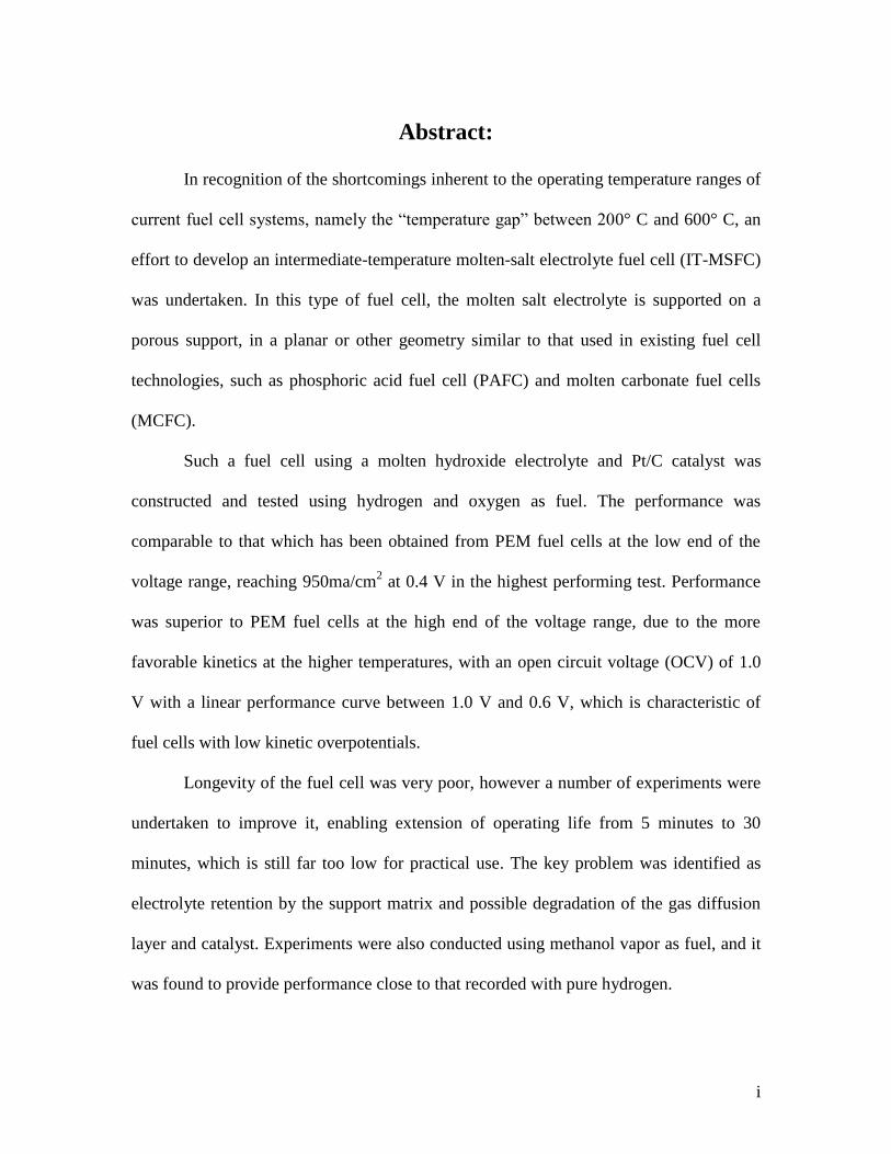
Such a fuel cell using a molten hydroxide electrolyte and Pt/C catalyst was
constructed and tested using hydrogen and oxygen as fuel. The performance was
comparable to that which has been obtained from PEM fuel cells at the low end of the
voltage range, reaching 950ma/cm2 at 0.4 V in the highest performing test. Performance
was superior to PEM fuel cells at the high end of the voltage range, due to the more
favorable kinetics at the higher temperatures, with an open circuit voltage (OCV) of 1.0
V with a linear performance curve between 1.0 V and 0.6 V, which is characteristic of
fuel cells with low kinetic overpotentials.
Longevity of the fuel cell was very poor, however a number of experiments were
undertaken to improve it, enabling extension of operating life from 5 minutes to 30
minutes, which is still far too low for practical use. The key problem was identified as
electrolyte retention by the support matrix and possible degradation of the gas diffusion
layer and catalyst. Experiments were also conducted using methanol vapor as fuel, and it
was found to provide performance close to that recorded with pure hydrogen.

ii
Experiments were also conducted using several alternative molten salts, including
nitrate and chloride eutectics. Combinations of nitrates with hydroxides added to act as a
charge carrier produced a working fuel cell, however performance was greatly reduced.
Though preliminary, the work described herein demonstrates the great potential of IT-
MSFC, and outlines the work needed to make this type of fuel cell practical

iii
Acknowledgements:
I would like to express my gratitude to my advisor, Professor Ravindra Datta for
his guidance and advice throughout the course of my graduate studies. He is responsible
for my interest in the field of fuel cell technology and I would not have otherwise pursued
this research.
I would also like to thank my friend and fellow graduate student, Saurabh Vilekar
for his help getting acclimated to the laboratory and for his insight and input throughout
the course of my work. I would also like to thank Jack Ferraro for his help with
fabricating items needed for my experiments. Finally I would like to thank all the
members of the chemical engineering department for being there when needed.

iv
Table of Contents
Abstract ................................................................................................................................ i
Acknowledgements ............................................................................................................ iii
List of Figures .................................................................................................................... vi
List of Tables ................................................................................................................... viii
Chapter I: Motivation .......................................................................................................... 1
Chapter II: Background....................................................................................................... 6
Chapter III: Molten Salt Fuel Cells for Intermediate Temperature Range ....................... 22
Why Molten Salts? ........................................................................................................ 23
General supported molten salt fuel cell system ............................................................ 24
Electrolyte considerations ............................................................................................. 27
Chemical stability ..................................................................................................... 29
Support material considerations .................................................................................... 32
Support structure and fabrication considerations .......................................................... 38
Catalyst considerations ................................................................................................. 43
GDL considerations ...................................................................................................... 45
Chapter IV: Experimental Results .................................................................................... 48
Experimental setup........................................................................................................ 48
Initial feasibility studies ................................................................................................ 53
Modified Zirconia Cloth ............................................................................................... 67
Performance Evaluation of KOH/Treated ZYW-30A System ..................................... 70
Methanol Fuel ............................................................................................................... 78

v
Non-hydroxide molten salt electrolytes ........................................................................ 82
Chapter V: Future Work ................................................................................................... 87
Improving Stability ....................................................................................................... 87
Nickel catalyst and higher operating temperature ........................................................ 91
Alternative catalysts and charge carriers ...................................................................... 92
Non-hydrogen Fuels...................................................................................................... 95
Chapter VI: Conclusions ................................................................................................... 97
Appendix A: Experimental Procedures .......................................................................... 102
References ....................................................................................................................... 114

vi
List of Figures:
I-1: Diagrammatic representation of the temperature regimes of fuel cell technologies .... 5
II-1, Polarization curve reported for a zirconium phosphate membrane fuel cell in 1964 11
II-2: Polarization curve for GDC–CSC IT-SOFC ............................................................ 14
II-3: Polarization curve reported for a direct ammonia fuel cell based on a molten alkali17
II-4: Schematic of the liquid tin anode ............................................................................. 19
III-1: Schematic of an IT-MSFC....................................................................................... 25
III-2: Definition of contact angle ...................................................................................... 34
III-1: Definition of contact angle ...................................................................................... 34
III-3: Comparison between two zirconia textiles .............................................................. 42
IV-1: Fuel Cell, assembled without insulation ................................................................. 51
IV-2: Fuel Cell, assembled with insulation, connected to test setup ................................ 52
IV-3: Rapid voltage oscillations during testing ................................................................ 58
IV-4: Proposed explanation for rapid performance oscillations ....................................... 59
IV-5: iV Curve for KOH FC (1) ....................................................................................... 61
IV-6: iV Curve for KOH FC (2) ....................................................................................... 64
IV-7: A used MEA, showing significant browning .......................................................... 66
IV-8: iV curve for KOH FC with ZrO2 treated support ................................................... 72
IV-9: iV Curve for KOH FC with 2x ZrO2 treated support ............................................. 73
IV-10: iV Curve with 2x ZrO2-treated support and cloth GDE ....................................... 77
IV-11: MEA from second direct methanol experiments................................................... 81
IV-12: MEA used with nitrate eutectic with 20% added hydroxide ................................. 85
V-1: Diagram of idealized pore structure ......................................................................... 90

vii
V-2: Alternative charge carrier concept ............................................................................ 93
A-1: Proper assembly of bolt and insulator .................................................................... 112

viii
List of Tables:
III-1: Potential Molten Salt Electrolytes ........................................................................... 31
III-2: Potential support materials for use in IT-MSFC ..................................................... 37
III-3: Potential fabrication methods for ceramic support matrices ................................... 41
III-4: Potential materials for gas diffusion layer ............................................................... 47
1
Chapter I
Motivation
Many of the problems which hold back fuel cells today can be seen as a
consequence of the temperature range dictated by the electrolytes in use today. For PEM
fuel cells, the temperature that the fuel cell runs at must be low enough that the polymer
membrane can stay hydrated and does not soften or break, which places an upper limit on
the operating temperature not much above 100° C. Phosphoric acid fuel cells (PAFC) and
alkaline fuel cells (AFC) require that the temperature be low enough that the electrolyte
will not evaporate during use (both of these reach their upper limit around 200° C). High
temperature fuel cells on the other hand require that the temperature be high enough for
the electrolyte to conduct ions across the membrane – for MCFC, the electrolyte needs to
be liquid, which requires temperatures of at least 625-650° C, while in a solid oxide fuel
cell (SOFC), the temperature must be high enough for the solid membrane to be
sufficiently conductive, which requires temperatures in excess of 750-800° C. This leaves
a large gap, between 200° C and 600° C, in which no existing fuel cells operate –
unfortunately, this would be the most desirable temperature range for a fuel cell to
operate in for most applications.
Fuel cells operating at low temperatures suffer from a number of common
problems caused directly by the low temperatures at which they operate. At temperatures
below 250-300° C, platinum must be used as the catalyst. Platinum has always been
extremely expensive, and prices have risen in recent years, presumably due to increased
demand for platinum due to it’s catalytic properties. At the current platinum loadings

2
required by low temperature fuel cells, there is not enough platinum in the earth to build
the quantity of fuel cells that would be needed in a full-scale hydrogen economy. At
higher temperatures, nickel is an effective catalyst for both the hydrogen and oxygen side
reactions, and it is relatively inexpensive and abundant.
Additionally, the efficiency of the oxygen reduction reaction (ORR) is poor in
low temperature fuel cells. The kinetics are poor, and a significant (0.3-0.4 volts)
overpotential is needed to increase the rate of reaction to a point where it is useful. This is
the dominant inefficiency in low temperature fuel cells, particularly PEM fuel cells (due
to the lower operating temperature). At higher temperatures, the kinetics naturally
improves, and the over potential is no longer significant.
One of the most important problems for low temperature fuel cells, however, is
CO poisoning. In PEM fuel cells operating at 100° C, as little at 100ppm of CO in the
hydrogen feed will reduce catalyst availability by 99%, effectively rendering the fuel cell
inoperative. There has been a large amount of work done on CO tolerant catalysts, both
for fuel cell and chemical catalysis applications, and this has led to only modest
improvements. One of the most effective means of improving CO tolerance at low
temperatures is alloying the platinum with ruthenium; unfortunately, ruthenium is even
more expensive than platinum. The binding of CO to Pt is strongly exothermic, however,
and increasing the temperature alone will dramatically improve CO tolerance. Phosphoric
acid fuel cells, which operate at 160-180° C can tolerate up to 5000 ppm of CO and still
maintain acceptable performance.
The problem with CO poisoning of the catalyst itself wouldn’t be such a severe
problem, were it not for the fact that CO is produced as a byproduct of most chemical
3
processes for producing hydrogen from hydrocarbons or biofuels. In such processes, the
fuel is first converted to a syngas, a mixture of water, hydrogen, CO and CO2, through the
process of steam reforming. In order to lower the CO concentration enough that a low
temperature fuel cell can operate, the syngas must be passed through at least one water
gas shift reactor (WGS), to convert water and CO to CO2 and hydrogen, and for PEM
fuel cells, there must be a second WGS reaction at a lower temperature to affect complete
removal of CO. Other methods of removing CO, including preferential oxidation (PrOx),
and electro-catalytic PrOx have been demonstrated as well. Any of these extra steps in
feed preparation greatly increase the cost and complexity of fuel cell systems that require
them.
High temperature fuel cells suffer from a different set of problems – the high
operating temperatures lead to material problems. Gaskets and sealing are a problem –
while there are countless elastomers available for low temperature fuel cells, these do not
work at the operating temperatures of high temperature fuel cells. At temperatures above
500° C, mild steel cannot be used for internal components [1], requiring expensive high
temperature alloys. Differences in thermal expansion coefficients become serious
problems, leading to failures upon cycling between room temperature and the operating
temperature. In solid oxide fuel cells, this is has been a particular problem. This
necessitates the use of more expensive materials and techniques.
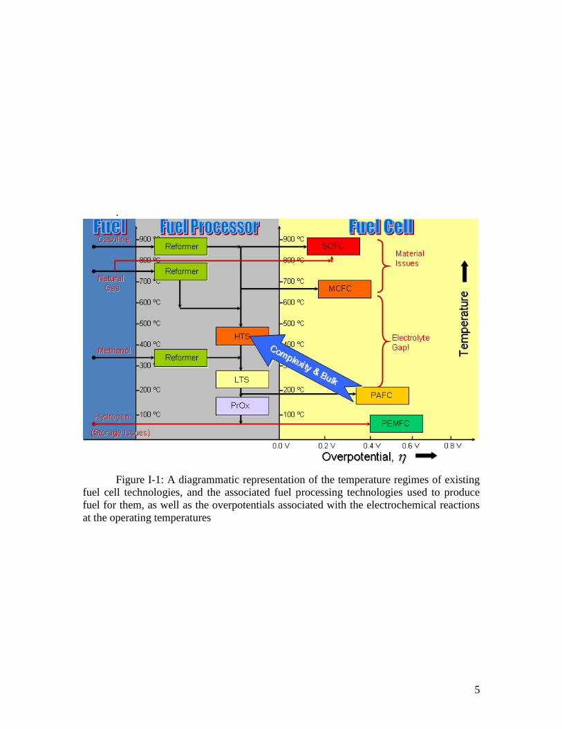
High temperature fuel cells also require bulky insulation, so that they can
maintain the operating temperature from waste heat, and in large installations, so that the
waste heat could be used to raise steam instead of being lost to the environment. This
makes them unsuitable for portable applications, where the necessary volume and mass

4
of insulation would make them uncompetitive with other technologies, and in small
applications such as home power generators. These complexity and efficiency issues are
shown schematically in Figure I-1.
A fuel cell which operated in an intermediate temperature range, ideally the 300-
400° C would circumvent all these issues on both sides. The temperatures are low enough
that traditional materials would be suitable and excessive insulation would not be
required. The chemical engineering discipline has extensive experience operating
processes in this temperature range at low cost on large scales. The temperature is also
high enough that the efficiency of the ORR would be high, nickel could be used as a
catalyst, and CO would not poison the catalyst – and in fact would be oxidized to CO2
contributing to the power production of the cell. This temperature range is a “sweet spot”
where material and chemical factors are both favorable.
In this work, a new class of fuel cell, the intermediate temperature molten salt fuel
cell, which would operate between 200 and 500° C, is described. The design
considerations for the various components of such a fuel cell are discussed, and potential
obstacles enumerated. A number of experiments conducted to demonstrate the feasibility
of an IT-MSFC are described. These experiments confirm that an IT-MSFC is viable, and
could offer high performance, although a great deal of additional work will be required to
produce a practical fuel cell.
5
.
Figure I-1: A diagrammatic representation of the temperature regimes of existing
fuel cell technologies, and the associated fuel processing technologies used to produce
fuel for them, as well as the overpotentials associated with the electrochemical reactions
at the operating temperatures

6
Chapter II
Background
Over the years, despite the seemingly obvious advantages of an intermediate
temperature fuel cell based around a lower temperature molten salt, there has been very
little work done in this area. This work is summarized below.
Molten Nitrate Fuel Cells
During the 1970s and 1980s, a research group led by Pier Giorgio Zambonin
undertook an exhaustive investigation of the chemical and electrochemical properties of
molten alkali nitrates and nitrites, within the context of their potential use as electrolytes
in a fuel cell. The work of P. G. Zambonin sought to fully analyze the chemical and
electrochemical properties of molten alkali nitrates and mixtures of alkali nitrates and
nitrites, and their interactions with hydrogen and oxygen, in many cases utilizing various
forms of voltammetry to analyze electrochemical properties. Much of the research done
involved the detection of other species in the melt, or the examination of chemical
reactions that would be relevant in a fuel cell using a molten nitrate electrolyte.
The design of the fuel cell itself does not seem to be described in any published
work (at least in the English language – some of their work was published in Italian as
well). It can be surmised from their published work that their intention was the use of
molten nitrate and/or nitrite salts as a solvent for some other species that would act as a
charge carrier.

7
In the course of the investigation, the stability of the nitrate melt in contact with
hydrogen and oxygen was exhaustively investigated. It was found that hydrogen would
react with the nitrate in a nitrate melt [2] through the reaction H2+NO3‾ H2O + NO2‾.
While the reaction proceeded relatively slowly at 653K, the rate increased dramatically as
the temperature was raised. This reaction was found to be catalyzed by the presence of
the nitrite ions, making the process autocatalytic [2]. It is worth noting that the
temperatures used in this experiment were higher than those in most of the Zambonin
experiments, but other papers [3] suggest that this effect is significant at lower
temperatures as well. The reaction occurred over time scales of tens to hundreds of hours.
Similarly, nitrite was found to react with oxygen [4] to form nitrates through the
reaction ½ O2+NO2‾ NO3‾. There was no apparent autocatalytic effect like had been
found for the reaction of hydrogen with nitrate. The reaction of oxygen with nitrite was
postulated to involve intermediate species including peroxide (O22‾ ) and superoxide
(O2‾). This reaction took place over time scales of hundreds of hours. A further
investigation [5] showed that the reaction was indeed catalyzed strongly by the presence
of superoxide ions, with the presence of superoxide in concentrations of 10-3
mol/l
resulting in the reaction rate increasing by three orders of magnitude. In dry nitrate melts
[6, 7] oxygen will slowly form peroxide and superoxide ions, however even small
amounts of water decompose superoxide ions [6].
Much of the investigation by Zambonin et al was conducted using voltammetry.
In this technique, a melt is prepared, with two electrodes as well as a reference electrode
half cell (Ag/Ag+), connected by a porous wick (Zambonin used an asbestos wick). A
potential is applied, and continuously varied, and the current recorded. The resulting
8
graph shows the rates (as measured by current) of electrochemical reactions that occur at
different potentials. It can be used to investigate the potentials that reactions of interest
occur at, or as a means of determining the concentrations of species in the melt [7]. A
rotating disk electrode was used in the experiments to ensure that the results were not
masked by transport limitations of species near the electrodes. Procedures for analysis
were presented [7] for determination of concentrations of oxygen, hydroxide, superoxide,
and water in nitrate melts using voltammetry.
Investigations using voltammetry with a platinum electrode demonstrated
hydrogen in nitrate melts would only occur in the presence of a suitable proton accepting
species, such as OH- [8] or CO3
2- [9], the reaction with the latter species was analogous to
that which occurs in molten carbonate fuel cells. Hydrogen was found to be
electrochemically inactive in pure nitrate melts. It was suggested [2, 8, 9] that hydroxyl
radicals produced as an intermediate in the electro-oxidation of hydroxide ions could
catalyze the chemical reaction H2+NO3‾ H2O + NO2 – the applicability of this to
practical fuel cells is not clear, however.
Zambonin et al proposed use of ammonia as a carrier for hydrogen in a future
hydrogen economy [10, 11]. They demonstrated that ammonia could be effectively
broken down to release hydrogen at the electrode surface, at the same time that the
hydrogen was being electro-oxidized. Dissolved ammonia could act as the required
proton acceptor, as well. It was noted that ammonia is 2 orders of magnitude more
soluble than hydrogen in nitrate melts [11]. It is likely that this would be the case with
other molten salts as well.
9
The project was apparently deemed uninteresting, and work on this topic was
finally discontinued by the Zambonin group at some point during or after the mid 1980’s.
The reason was mentioned in passing in a much later article summarizing the work
conducted by the group [12]. When they attempted to build an actual fuel cell (after over
a decade of work), it was found that the nitrate melt was incompatible with the nickel
catalyst because of its strongly oxidizing nature. During operation, the nitrate oxidized
nickel to nickel oxide which formed a solid layer on the surface of the electrode, leading
to large irreversibilites. There was no mention of any attempt to use lithiated nickel oxide
as is done to address the same problem in molten carbonate fuel cells.
Zirconium Phosphate Solid Membrane Fuel Cell
In the 1960’s, work was conducted for NASA toward development of fuel cells
based on solid zirconium phosphate membranes. It was proposed that they could operate
at temperatures as high as 400° C [13], however tests were never reported at temperatures
higher than 165C, still within the low temperature regime. The membranes were
fabricated from a mixture of ZrO2 and H3PO4, and Zeolon H (a zeolite powder, added to
improve structural stability). The membranes were prepared in a two step process, first
“pre-sintering” the mixture of ZrO2 and H3PO4 at a temperature between 200 and 600° C
to prepare zirconium phosphate. This was then ground, mixed with the Zeolon H (and,
sometimes, additional phosphoric acid [14]) by ball milling, and then formed into the
membrane and sintered at a temperature of between 300 and 800° C. [13]
The performance reported was very poor (approximately 30ma/cm2), as shown in
Figure II-1, but the experimental setup was very crude. They reported good stability to
1200 hrs or more. It is possible that what these investigators believed was proton
10
conduction by the Zr(PO4)2 was actually conduction by phosphoric acid left in the
membrane from the production process (making it a zirconium phosphate supported
phosphoric acid fuel cell), or from a zirconium acid phosphate. They noted that the
electrolyte was of acidic pH, and they did not take steps to ensure removal of all of the
acid [14]. Their tests also showed that higher sintering temperatures reduced the amount
of acid in the membrane – however, this could have resulted from volitization of the acid
during sintering (again, a possibility not mentioned in their reports).
The zirconium phosphate fuel cell system was also investigated for use directly
with hydrocarbons [15]. Some degree of success was had with using butane, propane,
ethylene and ethane as fuels in place of hydrogen. Current densities reported were on the
order of 6-20 ma/cm2 with potentials lower than with hydrogen fueled cells. Open circuit
potentials were on the order of 0.6-0.8 volts. In these tests the fuel cell was operated
between 103 and 123C, which may explain, in part, the poor performance of the fuel
cells.

11
Figure II-1, Polarization curve reported for a zirconium phosphate membrane fuel
cell in 1964 using hydrogen fuel. Membrane made with 1:1:1 ratio of zirconium oxide,
phosphoric acid and Zeolon H [58].
12
Composite Solid Electrolyte Fuel Cell
More recently, research led by Bin Zhu at the Royal Institute of Technology in
Sweden has been conducted using composite solid electrolytes operating in the 250-600°
C temperature ranges. These fuel cells are in early stages of development, and utilize a
solid electrolyte composed of combinations of oxides, fluorides, and hydrides. The
charge carrying species is hypothesized to be either protons, hydroxide ions, or a
combination thereof. The description given in the articles do not address the likelihood of
a non-electrochemical reaction occurring between the diffusing species (for example, if
protons and hydroxides were both simultaneously diffusing, they would be expected to
react in the middle to form water).
It was demonstrated by Bin Zhu [16] as early as 1999 that solid ceramic
composites of Al2O3 with fluorides and chlorides could conduct either protons or oxide
ions at temperatures above 600° C. In these experiments it was reported that protons were
the dominant diffusing species. They were demonstrated in fuel cells, albeit with fairly
poor performance. Later work [17, 18] demonstrated improved performance could be
obtained by doping the fluoride electrolyte with a hydride (in this case, CaH2).
They reported that lower concentrations of hydride produced better performance
than higher ones. They theorized that large amounts of hydride promote hydride ion
conduction, which reduces efficiency and performance [17, 18], while low concentrations
would somehow contribute to overall transport by contributing hydride ion conduction
[17], which may somehow be converted to protons [19] – how this might be the case was
not described. It was also noted that performance of freshly fabricated fuel cells was
13
poor, but rapidly improved during operation [16, 17, 18] – possible reaction of the CaH2
with water at the cathode to form CaO or Ca(OH)2 may play a role in this effect [18].
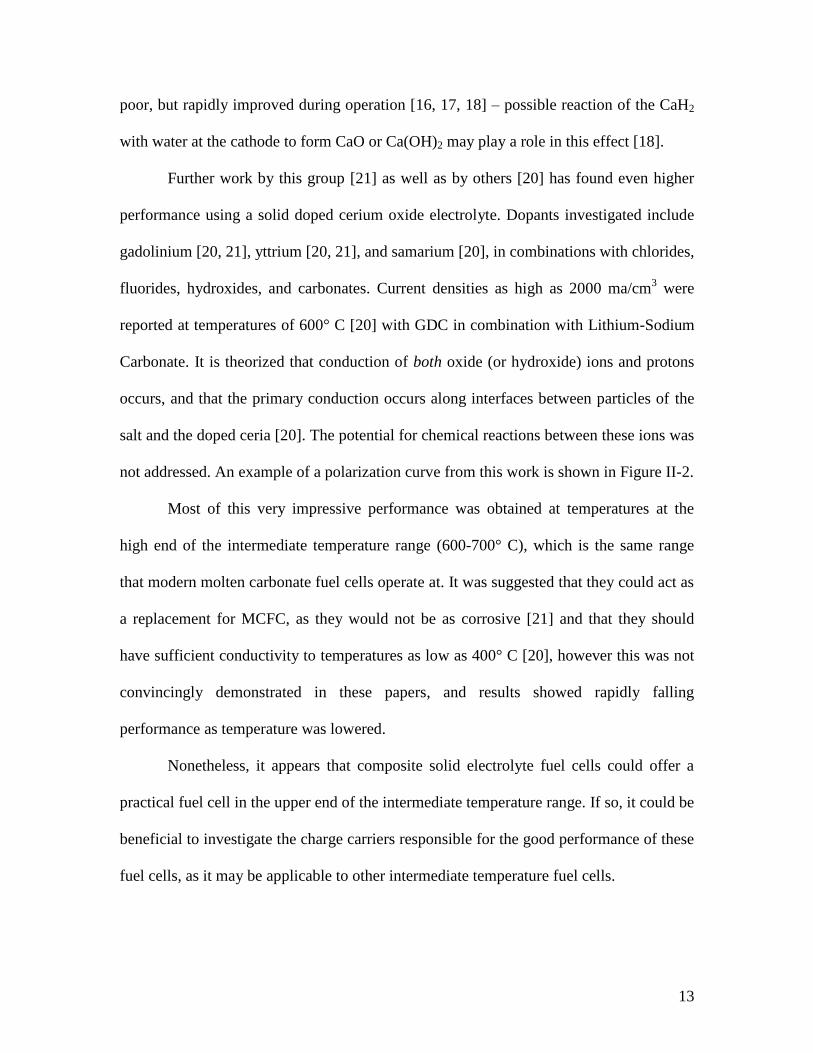
Further work by this group [21] as well as by others [20] has found even higher
performance using a solid doped cerium oxide electrolyte. Dopants investigated include
gadolinium [20, 21], yttrium [20, 21], and samarium [20], in combinations with chlorides,
fluorides, hydroxides, and carbonates. Current densities as high as 2000 ma/cm3 were
reported at temperatures of 600° C [20] with GDC in combination with Lithium-Sodium
Carbonate. It is theorized that conduction of both oxide (or hydroxide) ions and protons
occurs, and that the primary conduction occurs along interfaces between particles of the
salt and the doped ceria [20]. The potential for chemical reactions between these ions was
not addressed. An example of a polarization curve from this work is shown in Figure II-2.
Most of this very impressive performance was obtained at temperatures at the
high end of the intermediate temperature range (600-700° C), which is the same range
that modern molten carbonate fuel cells operate at. It was suggested that they could act as
a replacement for MCFC, as they would not be as corrosive [21] and that they should
have sufficient conductivity to temperatures as low as 400° C [20], however this was not
convincingly demonstrated in these papers, and results showed rapidly falling
performance as temperature was lowered.
Nonetheless, it appears that composite solid electrolyte fuel cells could offer a
practical fuel cell in the upper end of the intermediate temperature range. If so, it could be
beneficial to investigate the charge carriers responsible for the good performance of these
fuel cells, as it may be applicable to other intermediate temperature fuel cells.

14
Figure II-2: Polarization curve for Gadolinia Doped Ceria – Ceria-Salt Composite
IT-SOFC, showing excellent performance at the high end of the temperature range. [21]

15
Another research group has reported a dual phase electrolyte fuel cell operating at
500-600° C, made from doped ceria and molten sodium hydroxide [22]. The performance
reported is similar to the mid-range performance reported for straight doped ceria fuel
cells, though the authors compared their Dual Phase Electrolyte fuel cell only to those
with lower performance. They reported that the optimal concentration of NaOH was
about 12%, with concentrations higher or lower than this degrading performance. This is
notable in the similarity to what was found by Bin Zhu’s group regarding addition of
CaH2 to doped ceria [16, 17, 18], which supports the theory that its performance
improvements result from it’s conversion to the hydroxide.
Molten Hydroxide Electrolyte
It has been recently demonstrated [23] that a direct ammonia/oxygen fuel cell will
function at temperatures in the range, using a molten hydroxide electrolyte. Reported
currents were low, on the order of 50ma/cm2
as shown in Figure II-3, and the open circuit
potential was only 0.8 volts. However, these experiments were conducted in a crucible,
wherein the distance between the electrodes was 2cm, and the electrodes were not
optimized for current density. It is thus expected that much greater performance could be
obtained by a planar cell configuration.
This same team investigated the use of nickel catalysts with molten alkali. They
encountered problems with corrosion using pure nickel as the cathode – nickel was
oxidized to NiO, which is non-conductive, resulting in rapid degradation of performance.
However, they reported success in preparing corrosion resistant nickel catalysts with
good performance using lithiated nickel oxide. Nickel was electrochemically oxidized in
a 3M solution of LiOH at a current of 1ma/cm2 for 24 hours, producing a surface coating
16
of LiNiO2, which is conductive, and which protected the nickel underlying it from further
corrosion. This is the same material used for the cathode in molten carbonate fuel cells.
Good stability was reported. These results show that molten alkali hydroxides appear to
be promising electrolytes within the intermediate temperature range.
Direct Carbon Fuel Cells with Molten Salt Electrolytes
A number of groups have also conducted research on direct carbon and direct coal
fuel cells. These have met with mixed results, with the main problem being that coal and
charcoal are solids, making them more difficult to handle, and greatly complicating the
three-phase interface. In addition to the problem of handling a solid fuel, the kinetics of
the carbon oxidation reaction are terrible, necessitating high temperatures or other
measures. Much of the work has used molten salts as the electrolyte, however, and their
work is relevant in that regard.
A group using molten alkali hydroxide electrolytes had significant problems with
cell corrosion, settling on a ferrotitanium-lined container (which also served as the
cathode catalyst) [24]. Temperatures in the 400-615C range were necessary in order to
get acceptable performance and the performance and open circuit potentials were poor at
best (0.7 OCV and 100-200 ma/cm2 of anode area at 0.3V). Work has also been done to
develop “semi-fuel cells” based on carbon fuel and a molten alkali hydroxide electrolyte,
which would have a limited supply of fuel, but have higher energy density than other
primary batteries [25]. These were intended for use in military applications, similar to
thermal batteries.

17
Figure II-3: Polarization curve reported for a direct ammonia fuel cell based on a
molten alkali. Operating temperatures varied from 200° C to 450° C in 50 degree
increments, with steadily improving performance [24].
18
A key issue with direct carbon fuel cells with a molten alkali electrolyte is that
over time, the carbon dioxide will react with the molten alkali and form carbonates,
which have a much higher melting point [26]. The carbonation problems can be lessened
by addition of oxides such as MgO to the electrolyte, and greater success has been had by
addition of acidic oxides (including silicon or phosphorous oxides) to decompose the
carbonates, while maintaining humidified feed gas to convert the oxides formed from the
decarbonation back into hydroxides [26].
A number of direct carbon systems have been described in which a two step
process is used to oxidize the carbon fuel, in order to deal with the poor kinetics of
carbon oxidation. Very early investigations have been conducted [27] on using iron salts
in this manner. In this process, iron (II) is oxidized at the anode to iron (III), which then
oxidizes charcoal, and in the process is converted back to iron (II). This research is still in
a very early stage, but may have the potential to operate at temperatures in the low or
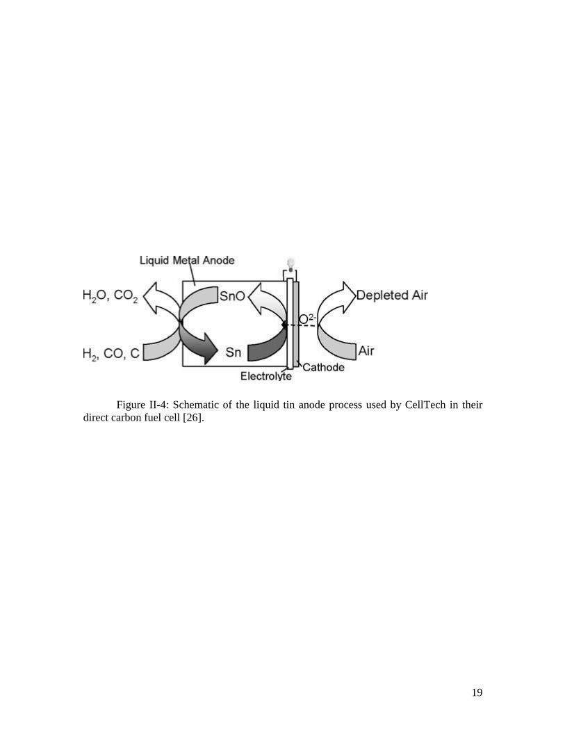
intermediate temperature range. In a similar concept, CellTech, a fuel cell development
company, is developing solid oxide fuel cells which use liquid tin at the anode, with the
tin being oxidized to SnO by oxide ions diffusing through the membrane, with the SnO
then being reduced back to metallic tin by carbon or coal fuel [26].
Use of carbon as a direct fuel in molten carbonate fuel cells has also been
investigated [28]. Performance was in the range of 50-125 ma/cm2
at 0.8V depending on
the type of carbon used in the fuel – biomass derived charcoal was best, while graphite
was worst. The operating temperatures were in the area of 800° C, however, far outside
of the intermediate temperature range.
19
Figure II-4: Schematic of the liquid tin anode process used by CellTech in their
direct carbon fuel cell [26].
20
Bromine and HBr Electrochemical cells
The system of bromine and hydrogen bromide has been investigated by several
groups for electrochemical applications. An electrolytic cell has been demonstrated
which can effectively electrolyze hydrogen bromide, a waste product of industrial
bromination processes, in order to recover the bromine [29]. This is relevant to the
development of intermediate temperature fuel cells because it operated in the same
temperature range and utilized a supported molten salt electrolyte using a planar
geometry, as is typical of fuel cells. The electrolyte used was a low melting point eutectic
of lithium-potassium-cesium bromide, which has a melting point of approximately 250°
C. It was supported on a yttria-stabilized zirconia fabric membrane made by Zircar
Zirconia, though the weave was not specified.
A tangentially relevant article has also mentioned exceptional current and power
density attainable with a low temperature hydrogen-bromine fuel cell [30]. This suggests
that the above described electrolytic process could be run in reverse to generate power.
The practical usefulness of this is questionable, probably limited in use to some sort of
regenerative fuel cell if anything, due to the fact that bromine is expensive relative to air,
and water is a far more benign exhaust product than hydrogen bromide.
Thermal Batteries
A somewhat related electrochemical technology that operates in the same
temperature range is the thermal battery. These are one-time-use batteries designed for
military applications, which have long shelf lives, and high performance. They contain a
fuel and an electrolyte which is solid (and hence inactive) at room temperature. The fuel

21
is generally a highly reactive alkali metal (often sodium, lithium, or calcium, often at a
temperature at which it is liquid during operation). A pyrotechnic composition is packed
around the battery, and ignited to activate the battery, rapidly heating the thermal battery
to the operating temperature, melting the fuel and electrolyte. These are commonly used
in weapon guidance systems.
The operating temperature of thermal batteries is in the low end of the
intermediate temperature range being investigated in this paper. A significant amount of
government backed research has been directed towards improving the power density of
these devices. An investigation of molten nitrate electrolyte thermal batteries showed that
they worked, which suggests that molten nitrates may in fact be a suitable electrolyte.
The fuel used in the nitrate-based thermal batteries was solid calcium metal. It was noted
that at temperatures of 400° C, the cell sometimes “deflagrated” [31], which is to say, it
caught fire and burned vigorously (as a flare would). Although the conditions of a
thermal battery are particularly conducive to such an occurrence, this suggests that great
care should be taken when working with molten nitrates at high temperatures.

22
Chapter III
Molten Salt Fuel Cells for Intermediate Temperature Range
Despite the obvious benefits of a fuel cell operating in the intermediate
temperature range (200-500° C), the volume of research within this temperature range is
quite low – the research summarized above comprises the majority of published work on
fuel cells within this temperature range. This temperature range was selected to start at
the temperature where CO poisoning and ORR overpotentials are no longer major issues,
up to the maximum temperature for which steel internals are suitable.
The main stumbling block to the development of fuel cells that operate in this
temperature range is a lack of suitable electrolytes. These temperatures are pushing the
lower limit of the conductivity range of dense ceramic electrolytes – the results of the
work on Ceria-based ceramics have yet to demonstrate effectiveness in most of the
intermediate temperature range. On the other hand, a polymer electrolyte would be
unlikely to endure such temperatures – no ion conducting polymers that stand up to such
high temperatures are known, and very few polymers at all are stable at those
temperatures.
A supported liquid electrolyte is one of the most promising options for a fuel cell
in those temperature ranges. The general setup – a liquid electrolyte supported on an inert
porous support has been used successfully in PAFC, AFC, and MCFC – which are the
cells operating on either side of this temperature range. PAFC and AFC are confined to
the low temperature range due to the volatility of components of their electrolyte. Molten
salts, however, would be expected to meet the general requirements of a fuel cell
23
operating in that temperature range, and indeed, there is are no other obvious options for
a liquid electrolyte in that temperature range.
Why Molten Salts?
The category of molten salt fuel cells offers a great variety of options based on
different molten salts and different combinations thereof, with different operating
temperature ranges. Molten salts meet the general prerequisites for an intermediate fuel
cell electrolyte, while at the same time offering a wide array of parameters which can be
changed to adjust the performance and operating characteristics of the fuel cell.
A molten salt by nature has the highest concentrations of ions possible, and so
they would be excellent ion conductors (at least for the appropriate kind of ions). At the
same time, molten salts are generally not electronically conductive (outside of conduction
involved with ion transport). They also generally have very low vapor pressures due to
the strong interaction between the positive and negative ions – this is a problem in
existing liquid electrolyte fuel cells (particularly phosphoric acid fuel cells, where the
volatile electrolyte is highly corrosive and not readily replenished).
Molten salts offer a great degree of control over the melting point, because a
given anion or cation which is desirable could be paired with a variety of different
counter-ions, and many classes of salts form eutectics (e. g., Na/K carbonate used in
molten carbonate fuel cells) which can allow lower melting points to be reached if that is
needed [32]. Similarly, other physical properties could be adjusted in the same way. Also,
molten salts are good solvents, and useful additives might be added to the electrolyte in
low concentrations to improve performance. Such additives could act as a charge carrier,
so that the other molten salt was only acting as a nonvolatile solvent, or they could act as
24
the catalyst itself. In other situations, additives could act to inhibit or counteract
unwanted side reactions (such as formation of carbonates when using carbon-containing
fuel [27]).
All of these properties of molten salts suggest a great potential for molten salt
based fuel cells operating in the intermediate temperature range. There has been
surprisingly little work on molten salt fuel cells other than the high temperature molten
carbonate fuel cells, yet a great variety of possible systems exist to investigate. It is for
this reason that we believe that research in this area will most likely be fruitful – there is
not only great reason to expect that these fuel cells will work, but a great number of
unexplored possibilities to try if one system does not produce satisfactory results.
General supported molten salt fuel cell system:
An intermediate-temperature molten-salt fuel cell (IT-MSFC) would consist of a
molten salt electrolyte, which would most likely melt just below the operating
temperature range. The molten salt would be supported in a porous matrix, most likely
some form of ceramic (either a woven cloth, or a tape-cast ceramic membrane, as is used
in MCFC and PAFC). An electrode, consisting of a current collector and a catalyst layer
will be located on either side of the supported electrolyte layer. There may be an
additional gas diffusion layer (GDL) between the electrode/current collector and the
bipolar plates, but as with existing fuel cells, the current collector would most likely
double as a GDL. This is shown diagrammatically in Figure II-1.

25
Figure III-1: Schematic of an IT-MSFC, using either a proton or oxygen
conducting electrolyte, showing the anode and cathode reactions.
26
During operation, at the interface between the catalyst layer and the electrolyte,
the fuel gas or oxygen will be catalytically converted to an ion, which will diffuse
through the electrolyte, and react with the other species at the catalyst layer on the other
side. Depending on the choice of electrolytes, there are several options for the diffusing
ion. A proton conducting electrolyte could conduct H+ ions generated at the anode in a
manner similar to the Nafion membrane in PEM fuel cells.
Alternately, oxygen could be carried across in the form of hydroxide ions
(produced from water and oxygen at the cathode), or as a simple oxide ion (though this is
less likely). It is also possible that another charged species could be created by reaction of
a fuel gas with a component of the molten salt mixture. While less desirable, a system
similar to the molten carbonate fuel cell might also be possible, where a carrier gas reacts
to form the diffusing species, and then is regenerated on the other side, where it must be
recycled. Technically, this is what happens in the case of hydroxide ions as the diffusing
species, but recycling water is far easier than recycling carbon dioxide (or most other
gaseous species that might be used in this way). An ideal carrier molecule would have a
low volatility, and would thus remain in the molten salt, diffusing back and forth between
the anode and cathode.
In the case where an oxygen containing ion is the diffusing species, additional
fuel flexibility is offered – the fuel need not be readily convertible to protons, as is the
case in PEM fuel cells, and could be directly oxidized without reforming. In such a
system, carbon monoxide, instead of being a problematic fuel contaminant would act as a
fuel. A similar effect could be obtained, less directly, in a fuel cell based on proton
conduction, through a water-gas shift reaction occurring on the anode, to produce
27
hydrogen from water and CO, which could then be converted into protons and conducted
through the membrane.
The design of an IT-MSFC can be divided into three parts: first, the molten salt
electrolyte used, second, the porous electrolyte support, and third catalyst and electrode.
All three of these however are closely interrelated. The support which works well for one
molten salt may not work as well (or at all) for another salt, or different fabrication
techniques may be needed. While less closely bound to the choice of the electrolyte, the
catalyst and gas diffusion layer is dependant on the electrolyte as well.
Electrolyte considerations:
An electrolyte, in general, is a substance containing mobile ions. The conductivity
of the electrolyte is key to high performance in any sort of fuel cell. The conductivity, σ,
is given by:
i
iii DCzRT
F 22
Where F is the faraday constant, R is the gas constant and T is the temperature.
For each diffusing species, z is the charge, C is the concentration, and D is the diffusion
coefficient. In a fuel cell, it may be that not all species are important – only those which
are involved in the electrode reactions are relevant for a fuel cell.
The main requirements for an electrolyte for a molten salt fuel cell, in addition to
a high conductivity, are a melting point below the operating temperature, stability, and
compatibility with some sort of support. The most obvious way to ensure conductivity
would be to use a molten salt containing the ions to be conducted. In the case of a proton
conducting fuel cell, this would be some sort of acid salt, such as an acid phosphate or
sulfate. A molten hydride could work for conduction of hydride ions, as proposed by
28
Prodyot Roy [1], however, as in his work, there would have to be a means of prevention
formation of protons (or at least a means for prevention of the conduction of protons).
Molten hydroxides are ideal for conducting oxygen in the form of hydroxide ions.
Aqueous solutions of alkali hydroxides are already widely used in alkali fuel cells
operating within the same temperature range as PEM fuel cells [33]. A molten oxide fuel
cell would be unlikely, however, because the melting points of oxides are almost
universally very high, hence the solid oxide fuel cell.
Alternately the electrolyte could be a mixture of a salt containing the ion which is
being conducted, and another salt which serves only as a carrier or solvent. This would
allow a salt which has desirable physical properties (is stable, easy to support, has the
desired melting point, etc) to be used as a solvent, while a hydroxide or acid salt is added
to provide the ionic conductivity. In such a system, the concentration of the added charge
carrier would have to be high in order to provide good conductivity. In such an
electrolyte, of course, it is necessary to ensure that there is no reaction between the salts
in question. For example, adding a hydroxide to a melt containing zinc ions would result
in formation of zinc hydroxide, which immediately decomposes to zinc oxide, which is
insoluble and has a very high melting point.
This might not even be necessary, however - as has been demonstrated by
research on oxide/fluoride ceramic fuel cells, the electrolyte does not always need to
contain the ions that are being conducted at the time of manufacture – the diffusing
species can be formed in situ from the reactions at the electrode [17, 18, 19]. This effect
remains unverified experimentally in molten salt fuel cells however. Because of this, the

29
main constraints for initial consideration of an electrolyte for an IT-MSFC are the
melting point, and chemical and electrochemical stability.
Chemical stability:
A suitable electrolyte must be safe and stable over the operating temperature
range, and must not react to an unacceptable extent with the fuels. A researcher
investigating the use of a given salt should research the basic properties and uses of the
salt in question. In some brainstorming sessions, chlorates and per chlorates have been
suggested for their low melting point, however these are completely unsuitable, as they
readily decompose, liberating oxygen, in some cases explosively. Hydrides have been
used in ceramic fuel cells, but should be approached with great care, as they will react
with any trace of water (such as that produced as exhaust from the fuel cell) to form
hydroxides and hydrogen [19].
Some transition metal cations, have a tendency to readily change oxidation states.
For example, Tin (II) is oxidized in air to Tin (IV), and Copper (I) readily undergoes a
disproportionation reaction to Copper (II) and metallic copper. Transition metal salts may
also present electrochemical stability problems which could make them unsuitable for use
in fuel cells, unless the multiple oxidation states could be used as a charge carrying anion.
For these reasons, the chemical, thermal, and electrochemical stability of transition metal
salts should be thoroughly investigated before use.
Complex anions also may present problems. As was described by Zambonin, the
nitrate ion, while fairly stable, can react with the fuel under some conditions, potentially
degrading performance. Similarly, many complex anions are strong oxidizing or reducing
agents, and that can lead to reaction with the hydrogen or oxygen respectively, or with
30
the products, such as water or carbon dioxide. Chemical reactivity with the fuel gas is
very undesirable, as it results in wasted fuel, and generates waste heat, both of which are
undesirable. Reaction with products or fuel gas could consume the electrolyte over time
and/or result in undesirable byproducts. Potential issues with nitrates and common
contaminants in nitrate melts reacting with both hydrogen and oxygen were raised by
Zambonin et al [2, 4, 5].
Electrochemical stability is a closely related issue. In order to be suitable for use
in a fuel cell, the electrolyte must not undergo any sort of electrochemical reaction under
a ~1.1 volt potential (the maximum that would be expected to develop in a hydrogen-
oxygen fuel cell). This is unlikely to be a particular problem in with most salts that are
otherwise stable (even nitrates have a very wide electrochemical window), except in the
case of transition metal salts, which can easily change oxidation states. While this might
initially appear to be another reason why salts of those transition metals are not appealing
for use in a molten salt fuel cell, it might be possible to make this advantageous, by using
redox reactions on transition metal salts as a charge or ion carrier. This is discussed in
greater detail later.
Some potential molten salt electrolytes are shown in Table III-1. There are of
course many other possibilities.

31
Table III-1: Potential Molten Salt Electrolytes
Salt/Eutectic * Mp, C Advantages Disadvantages
KOH/NaOH (49.4) 170 [32] Low melting points
Very high ionic conductivity
(>1 S/cm) [34]
Relatively benign
Highly Corrosive
Tendency to “creep” up
some surfaces 85% KOH ~180
NaOH 318 [32]
NaOH/LiOH (27) 218
KOH/KBr (25) 300 As above, may have more
desirable physical properties
As above
Higher melting point
NaOH/Na2CO3(10) 210 May be formed if hydroxide electrolyte used with
carbonaceous fuel.
NaNO3/KNO3 (54) 222 [32] Electrochemical properties
extensively studied (by
Zambonin et. al)
Low melting points
Corrosive
No charge carrier
NO3- may react with H2
NO2- may react with O2
Decompose at 300-340°
C
Possible reactivity w/fuel
NaNO3/NaNO2(60) 228 [32]
LiNO3 254 [32]
(Li/Na/K) NO3
30/53/17
122 [32]
ZnCl2/NaCl/KCl
60/20/20
203 [32] Less corrosive
Low melting point
No charge carrier
Zn2+
forms ZnO in
presence of OH-
AlCl3/NaCl (37) 114 [34] Less corrosive
Very low melting point
No charge carrier
Al+3
forms oxide in
presence of OH-
LiCl/KCl (41) 352 [34] Less corrosive
Alkali metal ions are well
behaved
No charge carrier
High melting point
(Li/K/Cs)Cl
(57.5/13.3/29.2)
250 [29] No charge carrier
Cs salts often expensive
InI3/NaI (25) 85 Less corrosive
Very low melting point
No charge carrier
Indium is expensive
Forms oxides in presence
of OH-
InI3/CoI2 (6) 180 Less corrosive
* Number in parenthesis is mol % of second component for binary eutectics.
Numbers reported commonly vary between sources, by as much as 5%, with the same
reported melting points.
32
Support material considerations:
In contrast to the electrolyte, there are relatively few considerations for the
material of the electrolyte support, but the overall requirements are made more complex
by the importance of pore structure of the support matrix, determined by the preparation
process. The material of the support must not react with the electrolyte, yet also be
readily wet by the electrolyte. While material compatibility is a chemical consideration,
retention is governed as much by physical structure of the support matrix as the chemical
composition.
The contribution of the material of the support to the issue of electrolyte retention
is the degree to which the electrolyte wets the support material. This can be expressed as
the contact angle, θ. This is the angle made between the surface of the liquid in a pore,
and the wall of the pore. A liquid which readily wets the support material will have a
contact angle less than 90o, while one in which the liquid does not readily wet the support
material will have a greater contact angle. Obviously, a support which is readily wet by
the electrolyte will be a better support material.
In fact, within the liquid-filled pore, the pressure is actually higher or lower as a
result of the surface interactions. In order to maximize the electrolyte retention, a large,
negative pressure difference is desirable. This pressure serves to counteract pressure
differentials and other forces which might act to push the electrolyte out of the support.
33
The pressure difference between the liquid and the gas over the curved gas-liquid
interface is given by the Young-Laplace equation, which is the central equation
describing capillary action:
prP
cos2
Where γ is the surface tension of the gas-liquid interface, θ is the contact angle
between the liquid and the pore wall, and rp is the radius of the pore. This gives
theoretical support for the intuitive observation that a small contact angle is desirable – a
contact angle of less than 90° will ensure that the pressure differential is negative.
Additionally, a small pore size will increase the magnitude of the pressure differential.
These two traits are thus the two key factors in determining the electrolyte retention
properties of the support material.

34
Figure III-3: Definition of contact angle
35
Currently there are two types of commercial supported liquid electrolyte fuel
cells, the phosphoric acid fuel cell (PAFC) and the molten carbonate fuel cell (MCFC). In
PAFC, the acidic electrolyte precludes the use of many oxide ceramics, and Silicon
Carbide is used. SiC, unlike oxide ceramics, must be prepared as membranes through
sintering of a powder. In MCFC, the support material is generally tape-cast lithium
aluminum oxide – the addition of lithium improves the resistance of the material to the
corrosive, basic electrolyte. For an IT-MSFC, the requirements of the material will vary
greatly depending on the specific electrolyte – it is very unlikely that there exists a
support material that will work with all molten salt electrolytes.
Ceramics are the class of materials most suitable for use as a support, as the
support must obviously be electronically non-conductive, and retain its integrity at the
operating temperature. Many ceramics also have excellent chemical resistance as well,
further qualifying them for the role of electrolyte support. Another advantage of ceramics
is that there is a large volume of knowledge and experience in producing porous
ceramics, and a great deal of interest in research on exact control over the pore structure.
Alumina, being used in molten carbonate fuel cells, may be suitable with some
electrolytes, though the chemical resistance to strong bases is poor. Addition of lithium
oxide can improve the chemical resistance of alumina significantly. Silica is also a
possible material, with greater resistance to acids, but poor resistance to bases. Silica is
also used on a very large scale industrially for a variety of purposes, and so there is a
large body of knowledge regarding the processing of silica and production of porous
silica, and various additives which could modify the material properties of silica. Silica is
also very inexpensive.
36
Zirconia (ZrO2) is highly resistant to almost all types of chemical attack except
some strong acids (particularly phosphoric acid) [33], and is an attractive material for use
in this regard. Usually, zirconia is stabilized with yttria, to improve its thermal stability
[34]. Some rare earth oxides, such as ceria, might be effective as a material for a support
matrix as well. Gadolinia doped ceria is particularly interesting because it has been used
in lower temperature solid oxide fuel cells. Thus, in addition to acting as a support, it
might contribute significantly to the conduction of the molten electrolyte. Rare earth
oxides also offer some additional room for fine tuning, as there are a number of rare earth
oxides with similar, though not identical, properties.
The use of porous PTFE is also possible at the low end of the temperature range;
however, incorporating a molten salt into a PTFE matrix is more difficult compared to
ceramic matrices. PTFE is extremely non-polar and hydrophobic, with very weak surface
interactions with almost anything. This is one of the properties that leads to its excellent
chemical resistance, but it would also make it difficult to ensure that the electrolyte could
be retained within it.
Finally, asbestos has been used successfully as a support for alkaline fuel cells
working with a concentrated solution of hydroxides [30], and it stands to reason that this
material might also be effective as a support for an IT-MSFC. Being composed of fibers,
it is porous just like synthetic ceramic textiles, and has good chemical stability.
Unfortunately, asbestos fibers can easily become dispersed in the air, and when inhaled
are strongly carcinogenic. This hazard, as well as the restrictions on asbestos use related
to it, and the stigma attached to it makes it an undesirable choice.
Some potential support materials are listed in Table III-2.

37
Table III-2: Potential support materials for use in IT-MSFC
Material Advantages Disadvantages
PTFE Excellent chemical resistance
Could be fabricated with gasket built in.
Hydrophobic – may be difficult
to retain electrolyte.
Very limited temperature range
Alumina Good chemical resistance
High maximum operating temperature
Used in MCFCs, techniques might be
adaptable to IT-MSFC.
Available commercially as a cloth
Poor resistance to very strong
bases
Silica Good chemical resistance to acids.
High maximum operating temperature
Very widely used in industry
Inexpensive
Poor resistance to strong bases
Silicon
Carbide
Good chemical resistance to acids
Good material strength.
Used in PAFCs, techniques might be
adaptable to IT-MSFC.
Poor resistance to strong bases
Fabrication may be more
demanding.
Zirconia Excellent chemical resistance
High maximum operating temperature
Available commercially as a cloth
Low physical strength
compared to other ceramics
Less widely used – is a
specialty product.
Poor resistance to some acids
Ceria As zirconia, and may contribute to
conducting, particularly if doped with
other oxides.
Specialty product, expensive
Asbestos Naturally porous, with very small pore
size
Very good chemical resistance
High maximum operating temperature
Severe health hazard
Use restricted by safety laws
Severe stigma due to health
hazards

38
Support structure and fabrication considerations:
The pore structure of the support plays a very large role in determining its
effectiveness. There are three numbers relevant to describing the pore structure as it
relates to conductivity: the porosity, or void fraction, the pore size, and the tortuosity. In
order to make a good support, the porosity of the material needs to be large enough that
the conductivity is not unduly reduced, while the pore size is small enough that the
electrolyte is effectively retained. The specific structure of the pores is important as well,
because of tortuosity, a measure of the degree to which pores twist and turn. Generally,
the tortuosity is inversely proportional to the porosity, but this may not be true for the
case of a structured support matrix. The effective conductivity of a supported electrolyte
can be calculated as:
σeff = ε/τ σ
Where σ is the conductivity of the bulk electrolyte, ε is the porosity of the
support, and τ is the tortuosity.
The electrolyte is retained in the matrix through capillary action as discussed
above, and thus, the pore size and surface interaction is the key factor to determine the
electrolyte retention. The ideal structure would likely be a “honey comb” structure, where
each pore was very thin, straight, and directed straight through the plane of the matrix.
This may not be achievable in practice, at least in the short term, but that is what would
be theoretically most desirable.
Fabrication techniques for ceramic supports include the industry standard process
of Tape Casting, used to produce membranes for molten carbonate fuel cells. In this
process, the green ceramic is mixed with an organic binder, and formed into a thin “tape”,
39
which is then cut to the desired size, and then fired at high temperatures, possibly with a
calcination step following that to remove traces of the binder left after firing. The thermal
decomposition and subsequent removal of the binder leads to a pore structure, which is
controlled by changing the binder used and preparation procedures [35].
More recently freeze casting has been described for production of porous
ceramics of controllable porosity [36]. In this process, the green ceramic is wet with
water, and formed into the desired shape, and then chilled to below the freezing point of
water, resulting in formation of ice crystals. The water is then removed by application of
a vacuum, followed by firing, leaving a ceramic membrane with pores in the spaces
occupied by the ice crystals. Control of the pore structure is realized by changing the
speed of cooling, amount of water, and composition of the green mix.
Porous membranes of some ceramics can also be prepared through sol-gel
synthesis [34]. In this process, alkoxides (for example, silicon alkoxides for silica sols)
are dissolved in a solvent, and hydrolyzed. This can then be applied to a scaffold or
support, and dried, forming a porous layer. Control over pore size is achieved by
changing the composition of the sol – additives can include chelating agents, pore
formers, and yttria sources (for preparation of YSZ sol-solution). Porous silica is widely
produced by the sol-gel method (in preparation of desiccants, among other things),
through hydrolysis of silicon alkoxides. The analogous process can be used to prepare
yttria-stabilized zirconia and zirconia membranes with some modification [34].
A very different form of porous ceramic with potential as a support for a molten
salt fuel cell is a ceramic textile. Ceramic textiles can be made from a wide variety of
ceramics, including the oxides of zirconium, aluminum, silicon, and lanthanides. Ceramic

40
textiles have high porosities and high pore sizes, relative to ceramic matrices fabricated
through other methods, the specific porosity depending on the type of weave used and the
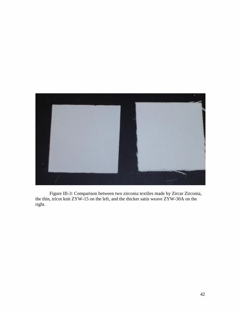
specifics of the manufacturing process. A comparison of two different weaves of zirconia
textiles are shown in Figure III-3. There is also a wide distribution of pore sizes within
any given type of ceramic textile. These are often used as separators and membranes in
high performance batteries (among other uses). One of the advantages of these is that
they are available as an off-the-shelf product from companies such as Zircar Zirconia
(which, despite the name, manufactures ceramic textiles from a wide variety of
materials).
The high porosity and large pore size of ceramic textiles may result in poor
electrolyte retention. One possible solution to this is to fill the pores in somehow, most
likely with more ceramic of the same type. Suspensions of nano-particles of zirconia and
other ceramics are available commercially which the textile could be soaked in and then
dried and calcined. Alternatively, the particles could be produced in situ through a
chemical reaction. Zirconia, for example, can be produced from zirconium alkoxides, and
this reaction could be carried out within a sample of zirconia textile to produce zirconia
which would (hopefully) adhere to the zirconia fibers and fill the pores.
Some methods for fabrication of porous ceramic support matrices and their
relative merits are summarized in Table III-3.

41
Table III-3: Potential fabrication methods for ceramic support matrices.
Method Advantages Disadvantages
Tape casting Well understood
Proven technology – used in
MCFC membrane production
May require pore formers
which must be later removed
Limited degree of control
Freeze casting Large degree of control
Water as pore former, easily
removed.
Relatively new technique
Sol-gel process No high temperature firing step
Pore size generally too small.
May require pore formers
May not work for all ceramics
Ceramic textile
modification
Uses off-the-shelf components
Rapid prototyping possible
Does not require extensive
ceramics processing equipment
or experience.
Limited control over pore
properties
Limited selection of textiles
available
Pore-filling agents may not
stay in the membrane
42
Figure III-3: Comparison between two zirconia textiles made by Zircar Zirconia,
the thin, tricot knit ZYW-15 on the left, and the thicker satin weave ZYW-30A on the
right.
43
The selection and development of an effective support material is one of the most
important considerations for the development of an effective IT-MSFC, as it governs
electrolyte retention, which is a prerequisite for further development. Because the key
factors in an effective support, electrolyte retention and chemical compatibility, both
depend directly on the electrolyte as well, it is likely that different support materials
and/or preparation methods will be needed for different electrolytes.
Catalyst considerations:
Compared to the other components of an IT-MSFC, the catalysts are better
understood and verified experimentally. The catalysts used would most likely be similar
to those used in existing fuel cell systems. The catalysts commonly used are platinum (at
low temperatures), and at higher temperatures nickel (on anode and cathode) and silver
(on the cathode) [17,18,19]. One of the primary benefits of the use intermediate
temperature range is that nickel could be used throughout most of the range; it is likely
that platinum would only see use in testing other components, particularly at
temperatures on the low end of the intermediate temperature range.
Above 250-300° C, no problems would be expected with the use of nickel
catalysts in an IT-MSFC, in terms of catalytic activity. Corrosion is a significant potential
problem, however, particularly on the cathode, and the presence of a molten salt
electrolyte can make matters worse. Many molten salts are highly corrosive – molten
hydroxides cause rapid corrosion of most metals, and Zambonin et al [18] reported that
molten nitrates caused corrosion of the nickel catalyst in a molten nitrate fuel cell.
In molten carbonate fuel cells, a similar problem is encountered: molten
carbonates are highly corrosive, and on the cathode, the nickel catalyst is rapidly
44
corroded if pure nickel is used, forming a non-conductive layer of nickel oxide on the
surface. In those fuel cells, the cathode catalyst is instead made from lithiated nickel
oxide, which is electrically conductive, and maintains the catalytic properties of nickel.
This solution could work for IT-MSFCs as well. A procedure for creating a layer of
lithiated nickel oxide is presented in [24], however it may not be suitable for catalysts in
the form of a finely divided powder, which is the form which practical catalysts are used
in.
A related problem encountered in molten carbonate fuel cells is “nickel short
circuit”, in which nickel oxide slowly dissolves in the electrolyte, diffuses to the other
side, and is reduced to nickel there. Over time (on the order of thousands of hours), the
nickel will eventually reach the other side of the matrix, resulting in a short circuit. The
severity of this problem is of course dependant on the solubility of nickel oxide in the
electrolyte. Unfortunately, the solubility of oxides (or any other salt) in molten salts,
especially mixtures of different molten salts, is not well documented. If an analogous
problem occurred in an IT-MSFC, study of solubility of nickel oxide in the electrolyte
would be the first step.
Silver also has potential for use as a catalyst for the oxygen reduction reaction.
Silver has been successfully used as a cathode catalyst for the solid oxide electrolyte fuel
cells made by Bin Zhu et al. The tests performed by this group took place at a
temperature range just above the upper end of the intermediate temperature range, and it
may be effective as a cathode catalyst for the purposes of an IT-MSFC. Silver-carbon
nano-capsules have been investigated as a catalyst for the ORR as well [37].
45
GDL considerations:
There also must be something to act as a gas diffusion layer to help evenly
distribute the fuel gasses. The GDL also serves as a current collector, to conduct electrons
between the catalyst and the bipolar plates. The GDL must also not absorb the electrolyte
or allow the electrolyte to infiltrate the GDL – if electrolyte enters the GDL, it will
prevent fuel or oxygen from reaching the catalyst. This can be insured, in principle, by
using a GDL material with pore sizes and wetting characteristics which do not favor the
retention of the electrolyte within the GDL, relative to it’s retention in the support matrix.
In PEM fuel cells, the GDL/current collector is normally PTFE-treated carbon
cloth. This material has many desirable qualities for use in an IT-MSFC. Being
hydrophobic, it repels most molten salts effectively. Unfortunately it is suitable only for
the lower end of the temperature range, because the PTFE coating that makes it
hydrophobic begins decomposing in the temperature range 260° C to 350° C
One of the most promising possibilities is a metallic GDL. Processes exist for
production of metallic sponge from a wide variety of metals. These have occasionally
been investigated for use as fuel cell GDLs, but not on a large scale. Alternately, one or
more layers of a fine-mesh metal screen could be used. “Expanded metal”, which is
similar to screen, but is produced by processing sheet metal instead of weaving wire, may
have more room for customization of properties. In an IT-MSFC, nickel or a high-nickel
alloy is the most likely candidate for the role of GDL, due to the high corrosion
resistance. Ferrotitanium sponge (Fe2Ti) has been used as a cathode catalyst with good
performance and stability in hydroxide-electrolyte direct carbon fuel cells [26]

46
Alternatively, the GDL and current collector could be separate, using a current
collector layer between the catalyst layer and a non-conductive GDL. This adds an
additional level of complexity, and significantly complicates connection and assembly of
the fuelcell. Nevertheless, this has been used by some researchers [29] in working fuel
cell prototypes. It allows use of macro-porous ceramic GDLs instead of potentially less
corrosion resistant metallic ones.
Some potential GDLs are listed in Table III-4

47
Table III-4: Potential materials for gas diffusion layer
GDL Material Advantages Disadvantages
Carbon Cloth Relatively inert
Inexpensive
Hydrophilic – electrolyte
could easily block gas
diffusion
Treated Carbon Cloth Hydrophobic Treatment limits operating
temperature
Nickel/alloy Screen High operating temperature
May act as an auxiliary
catalyst
Corrosion may be an issue
Few options for structure
Expanded Nickel/alloy High operating temperature
Variety of structural
customization options
May act as an auxiliary
catalyst.
Corrosion may be an issue
Separate current collector Ability to use non-
conductive GDL material
Added complexity
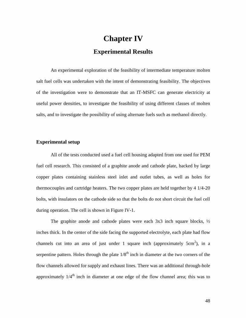
48
Chapter IV
Experimental Results
An experimental exploration of the feasibility of intermediate temperature molten
salt fuel cells was undertaken with the intent of demonstrating feasibility. The objectives
of the investigation were to demonstrate that an IT-MSFC can generate electricity at
useful power densities, to investigate the feasibility of using different classes of molten
salts, and to investigate the possibility of using alternate fuels such as methanol directly.
Experimental setup
All of the tests conducted used a fuel cell housing adapted from one used for PEM
fuel cell research. This consisted of a graphite anode and cathode plate, backed by large
copper plates containing stainless steel inlet and outlet tubes, as well as holes for
thermocouples and cartridge heaters. The two copper plates are held together by 4 1/4-20
bolts, with insulators on the cathode side so that the bolts do not short circuit the fuel cell
during operation. The cell is shown in Figure IV-1.
The graphite anode and cathode plates were each 3x3 inch square blocks, ½
inches thick. In the center of the side facing the supported electrolyte, each plate had flow
channels cut into an area of just under 1 square inch (approximately 5cm2), in a
serpentine pattern. Holes through the plate 1/8th
inch in diameter at the two corners of the
flow channels allowed for supply and exhaust lines. There was an additional through-hole
approximately 1/4th
inch in diameter at one edge of the flow channel area; this was to
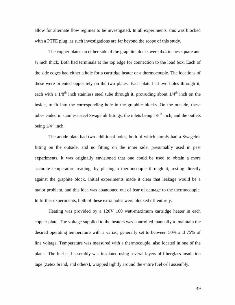
49
allow for alternate flow regimes to be investigated. In all experiments, this was blocked
with a PTFE plug, as such investigations are far beyond the scope of this study.
The copper plates on either side of the graphite blocks were 4x4 inches square and
½ inch thick. Both had terminals at the top edge for connection to the load box. Each of
the side edges had either a hole for a cartridge heater or a thermocouple. The locations of
these were oriented oppositely on the two plates. Each plate had two holes through it,
each with a 1/8th
inch stainless steel tube through it, protruding about 1/4th
inch on the
inside, to fit into the corresponding hole in the graphite blocks. On the outside, these
tubes ended in stainless steel Swagelok fittings, the inlets being 1/8th
inch, and the outlets
being 1/4th
inch.
The anode plate had two additional holes, both of which simply had a Swagelok
fitting on the outside, and no fitting on the inner side, presumably used in past
experiments. It was originally envisioned that one could be used to obtain a more
accurate temperature reading, by placing a thermocouple through it, resting directly
against the graphite block. Initial experiments made it clear that leakage would be a
major problem, and this idea was abandoned out of fear of damage to the thermocouple.
In further experiments, both of these extra holes were blocked off entirely.
Heating was provided by a 120V 100 watt-maximum cartridge heater in each
copper plate. The voltage supplied to the heaters was controlled manually to maintain the
desired operating temperature with a variac, generally set to between 50% and 75% of
line voltage. Temperature was measured with a thermocouple, also located in one of the
plates. The fuel cell assembly was insulated using several layers of fiberglass insulation
tape (Zetex brand, and others), wrapped tightly around the entire fuel cell assembly.

50
The fuel cell was controlled and monitored using a computer controlled Scribner
Associates Series 8908 Fuel Cell Test System. This system allowed either the current or
voltage to be fixed – however voltage is fixed by varying the load on the fuel cell, which
results in poor performance at low current densities, or in event of rapid oscillations, as
was discovered during early testing. The fuel and oxygen feed are controlled by the test
station, and are supplied at a controlled temperature. The fuel and oxygen lines from the
test station are 1/8th
inch PTFE tubes with Swagelok fittings. The fuel cell, connected to
the fuel cell test system, is shown in Figure IV-2.
In tests using direct methanol fuel, a crude methanol vapor generator was used.
This consisted of an Erlenmeyer flask containing methanol, heated by a hotplate, with a
stopper in the top of the flask. A 1/4th
inch tube through the stopper was connected to the
fuel cell. In the first test, this tube was unheated, and in the second test, it was wrapped in
heater tape, and maintained above the boiling point of methanol.
51
Figure IV-1: Fuel Cell, assembled without insulation.
52
Figure IV-2: Fuel Cell, assembled with insulation, connected to test setup
53
In all experiments the supported electrolyte layer was surrounded by a PTFE
gasket around its perimeter, and similarly separated from the graphite plates by PTFE
sheets covering all parts of the membrane except the active area. The fuel cell was heated
to operating temperature over the course of 40-60 minutes, depending on the operating
temperature used. Temperature control was performed manually. Although the fuel cell
test station provided a humidifier, it was found in early experiments to greatly degrade
performance, and was not used.
All of the data was taken through the computer controlled fuel cell test station.
Once the fuel cell stability had reached a point where doing so was feasible, the fuel cell
test system was used in arbitrary control mode. In this mode, a control file was used to
direct the test system to fix the voltage of the cell for 10 seconds, before recording the
current operating conditions of the fuel cell and moving to the next voltage. The tests
started at 1.0 V, and proceeded in a decreasing direction in increments of 0.05 volts.
When the minimum voltage (0.1 V , 0.4 V, or 0.55 V) was reached, the voltage was
returned to 1.0 V and the cycle repeated.
Initial feasibility studies
In the initial tests, a membrane made from Zircar ZYW-15 yttria-stabilized
zirconia knit cloth was used. The zirconia cloth membrane was cut to size (2”x2”) and
then loaded with a NaOH/KOH eutectic mixture by immersion in the molten salt at 200°
C. The membrane was then placed between two square aluminum plates, which were
protected by PTFE sheet. If the loaded membrane was not flat, it was placed in an oven at
200° C, until the electrolyte in it melted, at which point the force from the weight of the
metal plate flattened it. At this point, it was cooled at room temperature. During this
54
process it was noted that the hydroxide mixture appeared to melt 5-10 degrees below the
reported eutectic melting point. This was attributed to the presence of water (up to 15%)
present in the KOH as supplied by the manufacturer. The loaded membrane was then
used immediately or sealed in an airtight bag for storage.
The PTFE gasket was fabricated from several layers of 0.005” thick PTFE sheet,
such that it matched the loaded membrane in thickness, to avoid application of undue
pressure to the membrane. On either side of the membrane, an additional sheet of PTFE
with an opening only as large of the active area, and a thickness equivalent to the
electrode was used both to prevent the catalyst and GDL from applying excessive
pressure to the membrane and to minimize contact between the molten salt electrolyte
and the graphite plates, out of concern for possible corrosion of the graphite plates by the
caustic electrolyte (by the end of the tests conducted, evidence of only very minimal
corrosion was observed, despite electrolyte contacting the graphite plates in almost every
test).
For the catalyst and GDL, a catalyzed GDL material intended for use in PEM fuel
cells was utilized, EC 10-5-7. This material consisted of a PTFE treated carbon paper
GDL, with 10% Pt on carbon catalyst, with a platinum loading of 0.5 mg/cm2. This was
chosen because it was an off-the-shelf part, and would enable evaluation of feasibility
and basic performance in an expedient manner, without the variables that would be
introduced by a custom fabricated GDL and catalyst layer.
These initial tests demonstrated an open circuit voltage close to 1 volt (ranging
between 0.9 and 1.0 volts), as well as appreciable current density. Unfortunately, this was
found to be very short lived, with the voltage rapidly dropping shortly after reaching the
55
operating temperature of 180° C, with the open circuit voltage dropping below 0.3 volts
within 15 minutes or less. Because of the rapid degradation, it was impossible to
quantitatively assess the current or power density that the cell could produce.
On disassembly, it was found that most of the electrolyte had left the membrane,
leaving the cell through the outlet tubes or in some early tests, between layers of the
gasket. Although outright leaks of the electrolyte were remedied by increasing the
pressure applied to the gasket, it proved nearly impossible to keep the electrolyte from
rapidly leaving the membrane. The ZYK-15 membrane material was very thin, with
porosity as high as 85% (the pore size was unknown). It was assumed that the large pore
size of the zirconia cloth did not provide sufficient capillary pressure for retention of the
electrolyte, and as a consequence, the molten salt was easily forced out of the membrane
due to gravity and/or small pressure differentials between the anode and cathode side of
the cell. Those pressure differentials are nearly impossible to avoid, although later
experiments made some attempts to minimize them.
A number of other ceramic textiles from Zircar Zirconia were investigated. It was
confirmed that alumina was incompatible with the molten hydroxide. Zirconia cloth of
several different weaves and thicknesses was tested for electrolyte retention and cell
stability in operation. Three different weaves were investigated – ZYW-15, a simple
weave of thickness similar to the ZYK-15, ZYF-50, a much thicker felt, and ZYW-30A, a
satin weave of intermediate thickness.
The ZYW-15, because of its weave, had large holes visible to the naked eye
between the weave, and tests immediately confirmed that it was no better than the knit
cloth. The ZYF-50, which we had high hopes for, appeared to soak up a large amount of
56
electrolyte, which quickly left the membrane inside the sell, leading to repeated and rapid
clogging of the outlet tubes. Some method of “squeezing out” some of the electrolyte
during membrane loading might be effective for improving performance, but this was not
investigated. ZYW-30A demonstrated greatly improved stability, lasting for over an hour
without any reduction in open circuit voltage.
Performance did not correlate well with porosity, as the ZYW-30A had a porosity
of 83%, which is almost identical to that of the ZYK-15 – to a visual examination, the
porosity appeared to be vastly different, with the ZYW-30A having no visible pinholes,
and the ZYK-15 having many. This suggests that the pore size of the ZYW-30A was
significantly smaller. Unfortunately, no quantitative data was available from Zircar, and
they were either unwilling or unable to provide such data when requested. The
differences in performance underscore the importance of the specific structure of the
support, not merely it’s porosity or other easily quantifiable attributes.
Using ZYW-30A membranes, the open circuit voltage consistently remained
stable at 1.03 volts for an hour or longer. Unfortunately, while voltage was stable for an
hour or more, measurements of performance showed that rapid degradation of current
density did occur. When the load was removed, though, the open circuit voltage quickly
returned to the full 1.0-1.03 volts. This suggests a decrease in either the electrolyte
conductivity (due to loss of electrolyte) or a reduction in catalytic activity caused by
electrolyte leaving the support matrix and blocking the fuel gasses from accessing the
catalyst.
A pure KOH electrolyte was tested, in place of the eutectic. Although the reported
melting point is 360° C, commercially available KOH has up to 15% water in it (which is
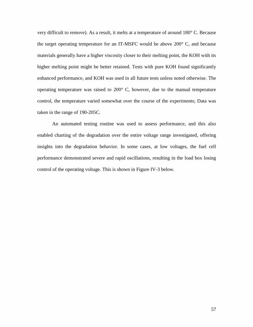
57
very difficult to remove). As a result, it melts at a temperature of around 180° C. Because
the target operating temperature for an IT-MSFC would be above 200° C, and because
materials generally have a higher viscosity closer to their melting point, the KOH with its
higher melting point might be better retained. Tests with pure KOH found significantly
enhanced performance, and KOH was used in all future tests unless noted otherwise. The
operating temperature was raised to 200° C, however, due to the manual temperature
control, the temperature varied somewhat over the course of the experiments; Data was
taken in the range of 190-205C.
An automated testing routine was used to assess performance, and this also
enabled charting of the degradation over the entire voltage range investigated, offering
insights into the degradation behavior. In some cases, at low voltages, the fuel cell
performance demonstrated severe and rapid oscillations, resulting in the load box losing
control of the operating voltage. This is shown in Figure IV-3 below.
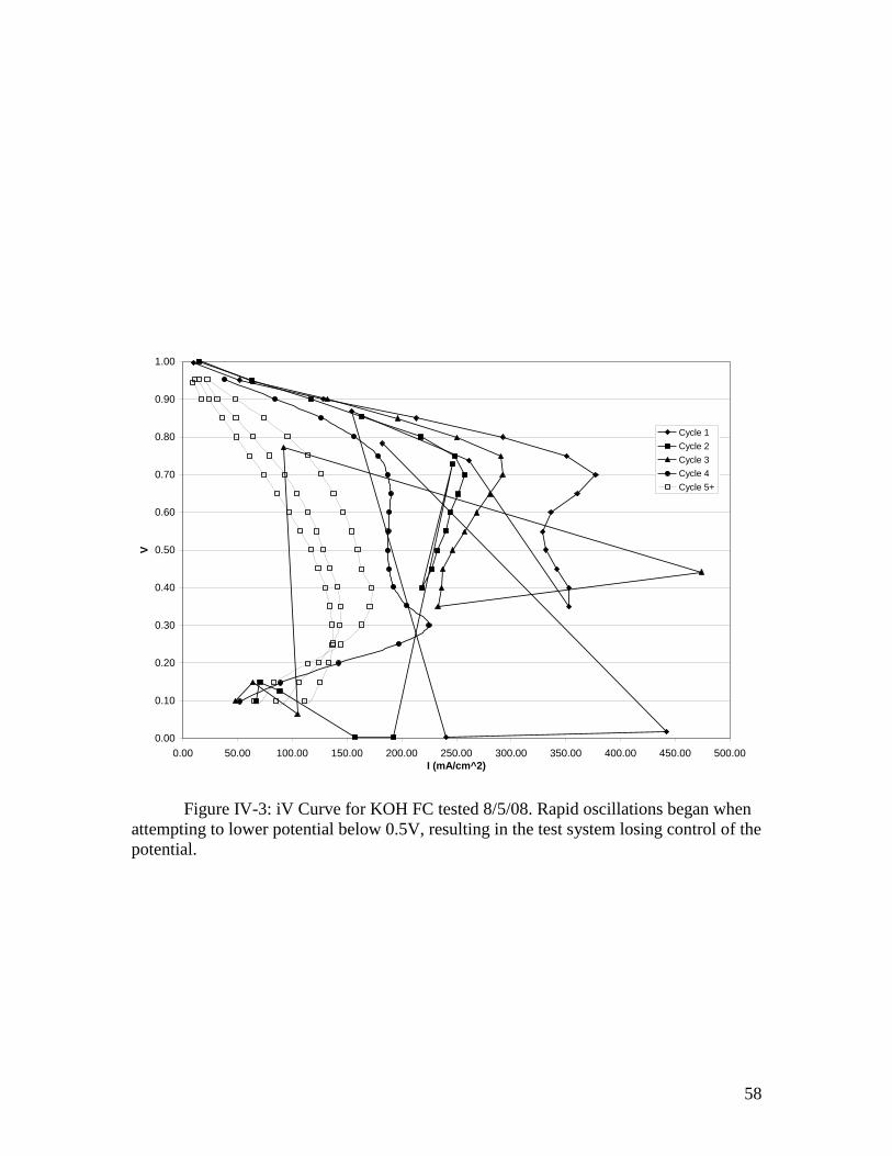
58
0.00
0.10
0.20
0.30
0.40
0.50
0.60
0.70
0.80
0.90
1.00
0.00 50.00 100.00 150.00 200.00 250.00 300.00 350.00 400.00 450.00 500.00
I (mA/cm^2)
V
Cycle 1
Cycle 2
Cycle 3
Cycle 4
Cycle 5+
Figure IV-3: iV Curve for KOH FC tested 8/5/08. Rapid oscillations began when
attempting to lower potential below 0.5V, resulting in the test system losing control of the
potential.
59
Figure IV-4: Proposed explanation for rapid performance oscillations. Not to
scale.
A) At high current, the H2 pressure drops faster than the O2 pressure, leading to a
pressure differential.
B) This pressure deforms the supported electrolyte layer, pushing either the GDL
out of contact with the graphite plate.
C) With the electrical connection broken, the reaction stops, and the pressures
equalize.
D) Electrolyte layer returns to normal position and cycle repeats
60
It was theorized that that high current densities, causing higher fuel consumption,
led to a small pressure differential developing between the hydrogen and oxygen side of
the fuel cell (since hydrogen and oxygen feed rates were the same, yet 2 hydrogen
molecules are consumed for each oxygen molecule); if the electrolyte layer and GDEs
were slightly loose this could push the supported electrolyte layer and GDE out of contact
with the graphite plate, interrupting operation of the fuel cell (illustrated in Figure IV-4).
When this happened, the pressures quickly equalized, and the cycle was repeated. This
problem could be solved by equalizing the pressures (which needs to be done anyway, in
order to prevent the electrolyte from being blown out of the support matrix), using a more
rigid support matrix, and/or by applying more force to the graphite plates, so that there is
no room for the support to move. This was never verified, and the problem did not
reoccur.
The test was repeated without the rapid oscillation occurring, and the performance
obtained is shown in Figure IV-5. It can be seen that the degradation was quite rapid –
each cycle lasted 190 seconds, and in both of these tests, within the span of a single cycle,
degradation could be seen over the course of the cycle – the reduced current as potential
is reduced is due to degradation occurring during the course of a single cycle.
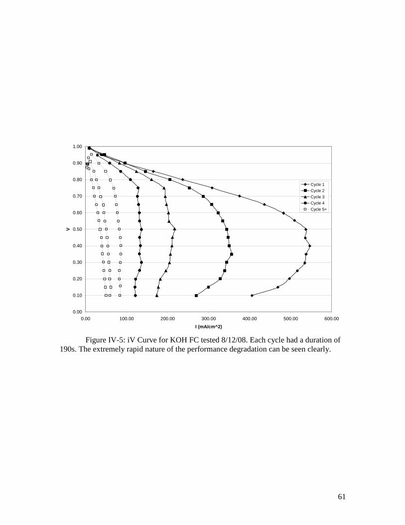
61
0.00
0.10
0.20
0.30
0.40
0.50
0.60
0.70
0.80
0.90
1.00
0.00 100.00 200.00 300.00 400.00 500.00 600.00
I (mA/cm^2)
V
Cycle 1
Cycle 2
Cycle 3
Cycle 4
Cycle 5+
Figure IV-5: iV Curve for KOH FC tested 8/12/08. Each cycle had a duration of
190s. The extremely rapid nature of the performance degradation can be seen clearly.

62
It was also observed that small pressure differences between the two sides of the
fuel cell would lead to much more rapid degradation, which is consistent with
degradation caused by loss of electrolyte – the electrolyte would be “blown out” of the
membrane. This pressure drop effect was minimized by placing the end of each outlet
tube under the surface of water in a beaker at an equal depth to carefully control the
pressure on each side.
Additionally, since much of the degradation appeared to occur at low potentials, it
was hypothesized that the large overpotentials could be a contributing factor to the
degradation, by promoting undesirable reactions which might damage the GDL – many
other fuel cells become damaged if operated at such low cell potentials for that reason.
The program was modified to test only between 1.0v and 0.4v for future tests.
These changes may have been responsible for the significantly higher
performance and stability shown in Figure IV-6, however there was a great variation
between identical samples, and so it is difficult to tell if this is the cause of the
improvement or not. Additionally, the testing of the fuel cell shown in figure IV-6 was
started just as the fuel cell entered the operating temperature range. It is theorized that
this may explain the higher performance of the second cycle compared to the first – the
electrolyte may have not completely melted, and as a result its conductivity may have
been lower.
Although none of the oscillations or rapid degradation in earlier samples was
observed, there were still several occurrences of a marked reversal of the slope. In the
earlier test, it was theorized that the reversal of the slow was a result of rapid ongoing
degradation. It is unclear what the cause of the reversals observed here were. The fact

63
that the ones in cycles 2 and 3 occur at the same potential suggests that there was
something special occurring at that potential, either a sudden increase in degradation, or
some other mechanism. This behavior has not been observed in most tests since this one.

64
0.30
0.40
0.50
0.60
0.70
0.80
0.90
1.00
0.00 100.00 200.00 300.00 400.00 500.00 600.00 700.00 800.00
I (mA/cm^2)
V
Cycle 1
Cycle 2
Cycle 3
Cycle 4
Cycle 5
Cycle 6+
Figure IV-6: iV Curve for KOH FC tested 8/13/08. Each cycle has a duration of
130s. Note improved performance of second cycle relative to first, and the unexplained
drop in performance at 0.45 volts in cycles 2 and 3, and at 0.65 volts in cycle 4.
65
Examinations of the fuel cell after operation suggested that a significant portion of
the electrolyte was still leaving the membrane. Electrolyte loss would lead to progressive
reduction of conductivity (and accompanying loss of performance), until pores between
the sides were no longer blocked by electrolyte, leading to mixing of the gases and an
accompanying drop in OCV. This matched the pattern of degradation observed. This
electrolyte which had escaped the membrane could also obstruct the flow of gas in the
serpentine channels on the graphite plates, in addition to infiltrating the GDL and
blocking access to the catalyst by the reactants.
In some samples, a dark brown, water soluble substance of unknown composition
was found within the electrolyte after operation. This was believed to be the result of a
secondary degradation process, possibly involving the GDL or graphite plate material.
This was not present in all samples, and did not correlate well with the extent of
performance degradation observed, while the degree to which electrolyte had leaked from
the membrane did. This was visible on some of the membrane-electrode assemblies
(MEA) after operation. A typical example of this is shown in Figure IV-7.

66
Figure IV-7: A used MEA, showing significant browning. This was typical of
MEA samples. The uneven distribution of browning is typical, and unexplained.
67
Modified Zirconia Cloth
The initial experiments had clearly verified that this was a promising avenue of
research. The most pressing problem, however, was that stability was so poor that it was
difficult to thoroughly characterize the performance of the fuel cell before it had
degraded severely. On the basis of evidence from investigation of the fuel cells after
operation, it was concluded that the main cause of the degradation was poor electrolyte
retention by the matrix, due to the very large pore size and high porosity of the
commercially available zirconia cloth.
The electrolyte retention is governed by capillary action, as described above.
Thus, the primary variables are the size of the pores, the strength of surface interactions
between the electrolyte and support, and the surface tension of the electrolyte. The
tendency of the support to retain electrolyte is opposed by forces like gravity and the
pressure differentials between the sides of the fuel cell. The viscosity of the electrolyte
also plays a role; a more viscous electrolyte will more strongly resist being pushed out of
a pore in the support. It’s worth noting that a small number of pores that are too large will
have a large effect on the performance – once gasses begin to pass between the two sides
of the fuel cell, performance will drop dramatically.
In the ZYW-30A zirconia support, the porosity was still too high (87%) compared
to membranes used in molten carbonate fuel cells (around 50%). This meant that a large
amount of electrolyte had to be supported within a relatively small amount of zirconia.
There was no other commercially available porous zirconia support material that would
be superior for this application, however. Casting electrolyte supports from scratch would
68
have involved a considerable expenditure of time and resources, and it was felt that it
would be more expedient to attempt to modify the ZYW-30A zirconia cloth in order to
reduce its pore size and porosity. This would allow a more thorough investigation of the
performance of the cell to be conducted, which could confirm the potential of this type of
fuel cell before developing a support casting process for a home-made support matrix.
If the membrane was to be modified so as to partially fill the pores, this would
need to be done by addition of some material which would be compatible with the molten
hydroxide electrolyte. The highly corrosive nature of the electrolyte made the addition of
more zirconia the natural choice for a pore filling material. A number of different
approaches to treating the support before introduction of the electrolyte were tested.
Nyacol ZR20-AC is a colloidal solution of zirconia in a solution stabilized by
acetate, manufactured by Nyacol Nano Technologies. This was tested by soaking a piece
of zirconia cloth with Nyacol solution and allowing it to air dry, followed by a second
drying stage at 250° C before loading it with the electrolyte. This was tested in the
normal manner, but the outlet tubes clogged before any data could be taken. Disassembly
of the cell revealed that the electrolyte retention had not been improved, and the zirconia
particles had been carried out along with the electrolyte. It was thus clear that simply
adding particles without some means of adhering them to the membrane would not be
successful.
Zircar Zirconia manufactures a zirconia rigidizer, ZIR-RIG, which it advertises
for use with its zirconia cloth products, for use as an adhesive, to improve rigidity of the
cloth, and to fill the pore space. It consisted of “sub-micron zirconia particles” in a
solution of zirconium acetate. The particle size of the ZIR-RIG was significantly larger

69
than that in the Nyacol, and the zirconia particles would settle out of the solution during
storage. In the documentation for ZIR-RIG, it was noted that in order to bind the zirconia
particles to the zirconia cloth, the mass had to be fired at 1000-1200F (530-650 C) after
drying.
Both ZIR-RIG and the Nyacol colloidal zirconia were tested via a new procedure.
The zirconia cloth was cut to size, and soaked with the solution (either ZIR-RIG or
Nyacol) and then dried in air. Two samples were prepared with Nyacol, and four were
prepared with ZIR-RIG for the first test, two in which the samples were blotted with a
paper towel after application of ZIR-RIG, and two in which this was not done. These
were dried in air for two days. This was followed by a drying step at 200° C, which
removed residual moisture as well as residual acetic acid. Finally, the dried, treated
supports were fired at 600° C for 24 hours. During all drying steps as well as the final
firing, it was necessary to hold the samples flat. Fine mesh stainless steel screens were
employed for this purpose.
After firing, the samples prepared with ZIR-RIG appeared similar to how they
had before firing, however, the sample prepared with Nyacol had darkened considerably,
and pinholes could be clearly seen. Testing of the membrane prepared with Nyacol found
that most of the electrolyte left the membrane immediately, and the outlet tubes clogged
before even reaching the operating temperature. The membranes treated with ZIR-RIG
performed well, and were far more stable than the untreated membrane. The degradation
still occurred fairly rapidly, but it was stable long enough for performance data to be
obtained. The membranes which had not been blotted showed higher performance,

70
suggesting that more pore filling material was better, and that multiple treatments might
improve performance further.
Performance Evaluation of KOH/Treated ZYW-30A System
With a fuel cell which was stable long enough for a performance curve to be
generated, a number of tests were conducted using the KOH/ZIR-RIG treated ZYW-30A
system. The operating temperature target was increased to 210° C for these tests. Actual
temperatures during operation varied between 200° C and 215° C due to the manual
control; however, no significant correlation was noted between small temperature
variations and performance or degradation behavior.
In the initial tests, the highest current densities measured during this study were
recorded. As shown in figure IV-8, current density reached 950 ma/cm2 at 0.4 volts. This
performance is comparable to PEM fuel cells at the higher end of the current density
range, and significantly better at very low current density, presumably because the higher
temperature reduced the 0.3-0.4 volt potential loss seen in PEM fuel cells due to poor
kinetics of the cathode reaction. Unfortunately, the degradation still occurred rapidly.
Electrolyte loss still occurred in this sample, albeit to a lesser extent.
Because tests of the first membranes fabricated suggested that additional gains
could be made by increasing the amount of pore-filler added, experiments were
conducted using membrane samples which had been given two treatments and three
treatments. In the preparation of these samples, all treatments were applied, each one
followed by an air-drying step, prior to the oven-drying step. The twice-treated samples
performed slightly worse than those coated only once, but they demonstrated a reduced
rate of degradation. An example is shown in figure IV-9. It is not clear if the increases in

71
longevity are due to improvements in electrolyte retention, or reductions in degradation
associated with high current densities.
In all cases, the reversals of the I-V curve that had been observed at high current
density in the untreated membranes were almost completely absent. This further suggests
that this rapid degradation may have been caused by electrolyte loss which resulted from
the tiny pressure differential that results from a high current density.
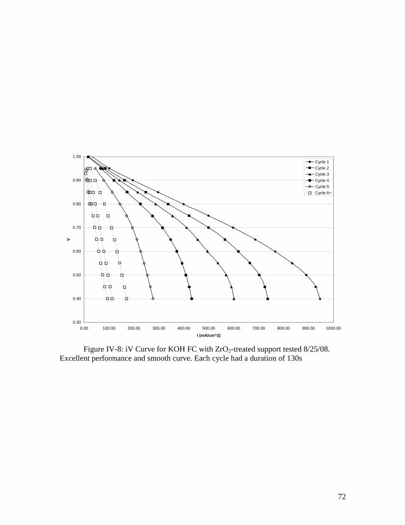
72
0.30
0.40
0.50
0.60
0.70
0.80
0.90
1.00
0.00 100.00 200.00 300.00 400.00 500.00 600.00 700.00 800.00 900.00 1000.00
I (mA/cm^2)
V
Cycle 1
Cycle 2
Cycle 3
Cycle 4
Cycle 5
Cycle 6+
Figure IV-8: iV Curve for KOH FC with ZrO2-treated support tested 8/25/08.
Excellent performance and smooth curve. Each cycle had a duration of 130s

73
0.30
0.40
0.50
0.60
0.70
0.80
0.90
1.00
0.00 50.00 100.00 150.00 200.00 250.00 300.00 350.00 400.00
I (mA/cm^2)
V
Cycle 1
Cycle 2
Cycle 3
Cycle 4
Cycle 5
Cycle 6+
Figure IV-9: iV Curve for KOH FC with 2xZrO2-treated support tested 9/8/08.
Significant loss in performance across the board, however significant improvements to
longevity can be clearly seen. Each cycle had a duration of 130s.

74
It was clear from these experiments that there was still some mechanism of very
rapid degradation at work. The brown substance that had been observed in initial tests
was much more prominent with the new membranes, and its presence appeared to be
dependent on the length of testing, and was roughly correlated with the degree of
degradation observed in the sample. In further tests, it was investigated whether operating
the cell at a high current density accelerated degradation. Setting the testing routine to
test between 1.0v and 0.55v instead of 1.0v and 0.4v resulted in modest improvements in
cell stability.
The only materials in contact with the electrolyte (under normal operating
conditions) were the GDE and the hydrogen and oxygen, and the membrane. The most
likely candidate for the source of the brown substance was the GDE, as there are no
obvious brown compounds that could be formed from H2, KOH, O2 and ZrO2. The
majority of the brown substance was found directly between the electrodes, further
supporting this theory.
The GDEs from several experiments in which severe degradation was observed
were removed and investigated, and compared to those in which the cell was only run for
a short time, and thus had no degradation (an example would be an experiment in which
the outlet tubes had clogged by the time the operating temperature had been reached). In
all samples, the catalyst layer was no longer strongly bound to the GDL. In most cases it
was very difficult to remove the GDL, and soaking in water to dissolve the electrolyte
was required. This strongly suggested that the electrolyte had indeed infiltrated the GDL.
When new, the PTFE treated GDLs are strongly hydrophobic (and thus should
repel both water and molten salts). This was the case with GDLs from samples for which
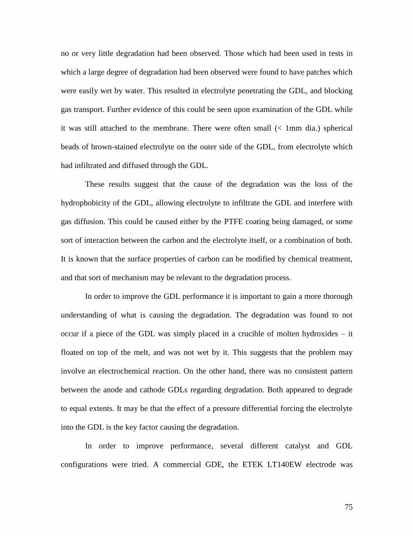
75
no or very little degradation had been observed. Those which had been used in tests in
which a large degree of degradation had been observed were found to have patches which
were easily wet by water. This resulted in electrolyte penetrating the GDL, and blocking
gas transport. Further evidence of this could be seen upon examination of the GDL while
it was still attached to the membrane. There were often small (< 1mm dia.) spherical
beads of brown-stained electrolyte on the outer side of the GDL, from electrolyte which
had infiltrated and diffused through the GDL.
These results suggest that the cause of the degradation was the loss of the
hydrophobicity of the GDL, allowing electrolyte to infiltrate the GDL and interfere with
gas diffusion. This could be caused either by the PTFE coating being damaged, or some
sort of interaction between the carbon and the electrolyte itself, or a combination of both.
It is known that the surface properties of carbon can be modified by chemical treatment,
and that sort of mechanism may be relevant to the degradation process.
In order to improve the GDL performance it is important to gain a more thorough
understanding of what is causing the degradation. The degradation was found to not
occur if a piece of the GDL was simply placed in a crucible of molten hydroxides – it
floated on top of the melt, and was not wet by it. This suggests that the problem may
involve an electrochemical reaction. On the other hand, there was no consistent pattern
between the anode and cathode GDLs regarding degradation. Both appeared to degrade
to equal extents. It may be that the effect of a pressure differential forcing the electrolyte
into the GDL is the key factor causing the degradation.
In order to improve performance, several different catalyst and GDL
configurations were tried. A commercial GDE, the ETEK LT140EW electrode was

76
tested. This GDE has the same catalyst loading as the one used previously, 0.5mg/cm2,
but used a PTFE-treated carbon cloth backing instead of carbon paper. This was more
flexible, and had a larger pore size. The stability of the new cloth GDE was comparable
to that of the carbon paper GDE, unfortunately the performance was reduced as well, by a
factor of 3-4, as shown in figure IV-10. It is unclear if this was a result of the GDL itself,
or whether differences in the catalyst formulation caused it. A similar test using an
untreated matrix was conducted, and resulted in very poor performance. After being used
in a test, the new GDL retained its hydrophobic nature.
77
0.30
0.40
0.50
0.60
0.70
0.80
0.90
1.00
0.00 20.00 40.00 60.00 80.00 100.00 120.00 140.00 160.00 180.00
I (mA/cm^2)
V
Cycle 1
Cycle 2
Cycle 3
Cycle 4
Cycle 5
Cycle 6+
Figure IV-10: iV Curve for KOH FC with 2xZrO2-treated support tested 9/8/08.
Using cloth GDE material. Longevity comparable to earlier experiments, but significantly
reduced performance. Each cycle had a duration of 130s.
78
In a related experiment, the commercial GDEs were replaced with platinum
screen electrodes, and catalyst-free PTFE treated carbon cloth. This would be expected to
give very poor current density because of the low catalyst surface area; however, if it did
not experience the rapid degradation seen in other tests, it would demonstrate that the key
problem was with the GDE, rather than with the support matrix. It was found that very
rapidly, electrolyte covered the platinum screen, blocking the transport of any gas to the
three phase interface. As a result, the current densities observed were so low as to be
barely measurable, though the OCV was close to 1 volt.
Although the experiments with the screen electrodes did not yield a system
suitable for testing, it demonstrated that the tendency of the electrolyte to leave the
membrane is a major contributor to the degradation of cell performance. In order to solve
the stability problem, some means of preventing the electrolyte from leaving the support
matrix, damaging the GDL, and blocking access to the catalyst is needed. Most likely,
this would require careful engineering of the pore structure of the support matrix and
GDL.
Methanol Fuel
One of the potential benefits of an intermediate temperature fuel cell is that at that
temperature range, a wider variety of fuels could be used, including methanol, ethanol, or
ammonia, without poisoning the catalyst. Methanol has been frequently discussed as a
direct fuel source for a fuel cell, and has the advantage of being a liquid, and thus more
easily transported, than hydrogen. Attempts to use methanol to fuel low temperature PEM
fuel cells directly have met with some degree of success, they still have very poor
performance. The most advanced direct methanol fuel cell catalysts are still greatly
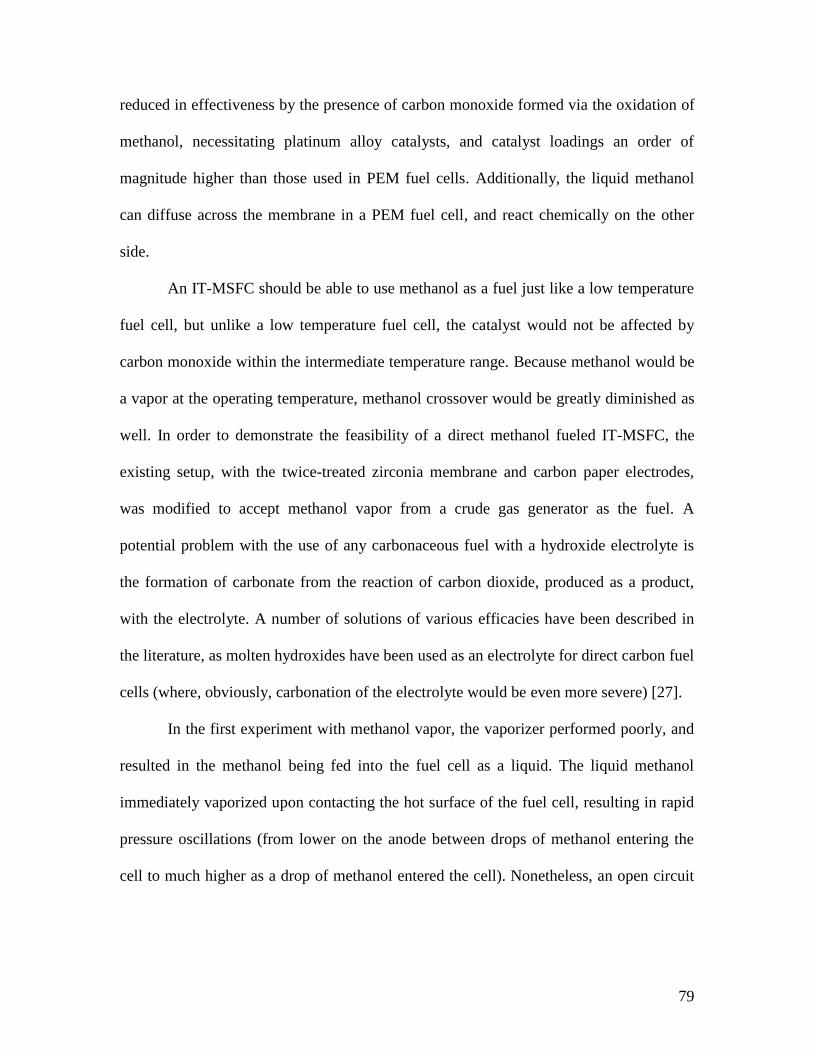
79
reduced in effectiveness by the presence of carbon monoxide formed via the oxidation of
methanol, necessitating platinum alloy catalysts, and catalyst loadings an order of
magnitude higher than those used in PEM fuel cells. Additionally, the liquid methanol
can diffuse across the membrane in a PEM fuel cell, and react chemically on the other
side.
An IT-MSFC should be able to use methanol as a fuel just like a low temperature
fuel cell, but unlike a low temperature fuel cell, the catalyst would not be affected by
carbon monoxide within the intermediate temperature range. Because methanol would be
a vapor at the operating temperature, methanol crossover would be greatly diminished as
well. In order to demonstrate the feasibility of a direct methanol fueled IT-MSFC, the
existing setup, with the twice-treated zirconia membrane and carbon paper electrodes,
was modified to accept methanol vapor from a crude gas generator as the fuel. A
potential problem with the use of any carbonaceous fuel with a hydroxide electrolyte is
the formation of carbonate from the reaction of carbon dioxide, produced as a product,
with the electrolyte. A number of solutions of various efficacies have been described in
the literature, as molten hydroxides have been used as an electrolyte for direct carbon fuel
cells (where, obviously, carbonation of the electrolyte would be even more severe) [27].
In the first experiment with methanol vapor, the vaporizer performed poorly, and
resulted in the methanol being fed into the fuel cell as a liquid. The liquid methanol
immediately vaporized upon contacting the hot surface of the fuel cell, resulting in rapid
pressure oscillations (from lower on the anode between drops of methanol entering the
cell to much higher as a drop of methanol entered the cell). Nonetheless, an open circuit

80
potential of 1.0 volts was recorded, with a potential of 0.75 to 0.85 volts at 200 ma/cm2 of
current – performance which is nearly identical to that obtained with pure hydrogen.
This performance was very short lived however. Within under a minute
significant degradation was evident, which progressed very rapidly. Examination of the
cell after the test was terminated confirmed that extensive electrolyte blowout had
occurred – which was expected due to the rapid pressure oscillations. When the
membrane was removed, it was found that so much electrolyte had left it that it was
slightly flexible (normally, the membrane is rigid due to the electrolyte being solid at
room temperature).
An attempt was made to provide a more consistent flow of methanol, by using a
heated tube from the methanol vaporizer to the fuel cell. Although this eliminated the
pressure spikes, it is likely that there was still a pressure differential between the two
sides of the fuel cell. Results obtained were similar to those obtained in the first test, and
upon removal, the MEA was found to have experienced severe blowout, causing it to
adhere to the graphite cathode plate with sufficient strength that the MEA was damaged
during removal. Additionally, significant catalyst migration had occurred. This is shown
in Figure IV-11.
81
Figure IV-11: MEA from second direct methanol experiments. Cracks were
caused during removal from fuel cell assembly. Note the swollen GDL, and significant
catalyst migration.
82
Non-hydroxide molten salt electrolytes
The vast majority of the work conducted in this study was done using a molten
hydroxide melt, either potassium hydroxide or a potassium/sodium hydroxide eutectic.
There is a great variety of other potential molten salt electrolytes which could be
investigated, and so a small selection of other molten salts and eutectics was tested.
Several molten chloride eutectics were investigated, including a CuCl/KCl
eutectic with a melting point of 150° C, a ZnCl2/SnCl2 eutectic with a melting point of
171C and a ZnCl2/KCl/NaCl eutectic with a melting point of 203C. A
LiNO3/NaNO3/KNO3 eutectic reported to melt at 120° C was also tested. The copper
chloride eutectic was immediately found to be completely unsuitable, as the CuCl
decomposed to CuCl2 and extremely fine metallic copper. The zinc/tin chloride eutectic
encountered a similar problem, forming an unknown white precipitate. Although it
briefly melted, a solid quickly formed which would not melt. It is hypothesized that the
Sn+2
ion was being oxidized by the air forming Sn+4
and oxide or hydroxide ions, which
formed solid salts with high melting points and which were insoluble in the melt.
The ZnCl2/KCl/NaCl mixture had no such problems, and could be loaded into the
membrane using the same process that had been used for the hydroxide electrolytes. It
was significantly more viscous than the hydroxide melts, which made it enter the
membrane more slowly. In tests, a fuel cell assembled with this membrane developed an
open circuit potential of 0.9 volts, but attempting to draw even the slightest current
resulted in the voltage dropping to zero, presumably due to a lack of carrier ions,
although it is possible that such ions could be formed in situ given sufficient time.
83
The nitrate eutectic was tested in a similar fashion. It was found that despite the
claims of the eutectic melting point being 120° C, it did not appear to melt until at least
150° C. Unlike the chloride eutectic, it could not be loaded into the membrane by
immersion in the molten salt. The molten salt did not readily wet the support matrix and
it would simply bead up and run off of the membrane, it likely that this was due to
unfavorable interaction between the two (a high contact angle). A new method of loading
the electrolyte, the “wet method” was developed to address this.
50g of the nitrates in the appropriate ratio was prepared, and dissolved in 50ml of
DI water. This was heated with stirring to just below 100° C and held at this temperature.
The membrane to be loaded was immersed in the solution, and then removed and allowed
to dry with heat (on the same hot-plate being used to heat the nitrate solution. This
process was repeated until no further nitrate solution was absorbed by the membrane. The
membrane so prepared was tested in the normal manner, giving performance results
which were very similar to those obtained from the chloride eutectic. Despite the fact that
the nitrate eutectic did not readily wet the matrix material normally, it did not leave the
support to a considerably greater degree than the hydroxide did.
It was assumed that the lack of charge carriers in these electrolytes was resulting
in the lack of performance. In order to address this, the nitrate electrolyte was prepared
with added sodium and potassium hydroxide (in the eutectic ratio) equal to 5% of the
mass of the nitrates, and loaded onto a membrane using the wet method. This too gave
similarly disappointing results. It is possible that in this test, during the exposure to air in
during the wet preparation method, the hydroxide could have absorbed carbon dioxide
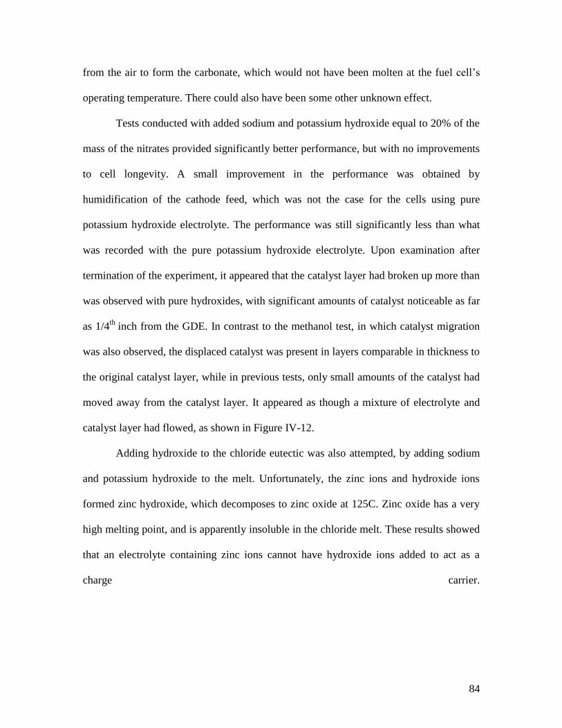
84
from the air to form the carbonate, which would not have been molten at the fuel cell’s
operating temperature. There could also have been some other unknown effect.
Tests conducted with added sodium and potassium hydroxide equal to 20% of the
mass of the nitrates provided significantly better performance, but with no improvements
to cell longevity. A small improvement in the performance was obtained by
humidification of the cathode feed, which was not the case for the cells using pure
potassium hydroxide electrolyte. The performance was still significantly less than what
was recorded with the pure potassium hydroxide electrolyte. Upon examination after
termination of the experiment, it appeared that the catalyst layer had broken up more than
was observed with pure hydroxides, with significant amounts of catalyst noticeable as far
as 1/4th
inch from the GDE. In contrast to the methanol test, in which catalyst migration
was also observed, the displaced catalyst was present in layers comparable in thickness to
the original catalyst layer, while in previous tests, only small amounts of the catalyst had
moved away from the catalyst layer. It appeared as though a mixture of electrolyte and
catalyst layer had flowed, as shown in Figure IV-12.
Adding hydroxide to the chloride eutectic was also attempted, by adding sodium
and potassium hydroxide to the melt. Unfortunately, the zinc ions and hydroxide ions
formed zinc hydroxide, which decomposes to zinc oxide at 125C. Zinc oxide has a very
high melting point, and is apparently insoluble in the chloride melt. These results showed
that an electrolyte containing zinc ions cannot have hydroxide ions added to act as a
charge carrier.
85
Figure IV-12: MEA used with nitrate eutectic with 20% added hydroxide eutectic.
Areas of notable catalyst migration are marked. In the areas in the upper and lower right,
marked with arrows, the catalyst had been carried to the back of the GDL, which had
never before been observed.
86
In summary, the experiments conducted have demonstrated that good
performance is possible in an intermediate temperature fuel cell using a molten KOH
electrolyte. Current densities approaching those in commercial PEM fuel cells have been
obtained. It has also been confirmed that the performance at high potentials has been
improved by reducing the kinetic overpotentials. Performance in fuel cells using chloride
and nitrate electrolytes was found to be very poor, because of the lack of a carrier ion.
Additions of hydroxide to nitrate were only marginally successful, and did no result in
any notable improvements. Additionally, it has been demonstrated that an IT-MSFC can
directly utilize methanol as a fuel, however the performance possible is unclear due to
rapid degradation. In all experiments the stability was very poor due to electrolyte
migration. However, these experiments have established the feasibility of the proposed
IT-MSFC system.

87
Chapter V
Future Work
Improving Stability
The foremost concern for future development of IT-MSFCs is improving the
stability of the fuel cell during operation. Currently, stability is not even sufficient for
advanced studies of the performance characteristics of the fuel cell. It is believed that
electrolyte infiltration and subsequent degradation of the GDL and/or catalyst layer,
which allows electrolyte to block access of the fuel gases to the catalyst, is the primary
cause of the rapid performance degradation. All of the GDEs used in these experiments
were intended for use in PEM fuel cells, so it is not surprising that they do not perform
well in an IT-MSFC.
Development of a GDL material for use in an MSFC would be one of the first
steps towards improving the stability. A GDL which remains hydrophobic and resists
infiltration and degradation by the electrolyte is needed. One of the promising approaches
is the use of a metallic GDL, such as a fine expanded metal mesh made from nickel or a
nickel alloy like Monel or Inconel. These alloys are resistant to highly corrosive molten
salt electrolytes, however, it is not clear if they would be effective at preventing the
electrolyte from entering the GDL and blocking the fuel gas from reaching the catalyst.
It may be necessary to use a separate current collector and GDL, with the GDL
being composed of a hydrophobic (and non-conductive) ceramic, paired with a current
collector (possibly nickel screen). The ceramic would also need to have an appropriate

88
pore size to resist infiltration as well. This would add complexity to assembly, but if a
metallic GDL is ineffective, it may be necessary.
Another key task, perhaps the most important one, for improvement of stability is
improving the electrolyte retention properties of the support. Because infiltration of the
electrolyte into the GDL is believed to be part of the degradation process, if the
electrolyte could be held more tightly in by the support, the degradation could be slowed
or prevented. The most expedient method that should be investigated is in situ production
of zirconia inside the zirconia cloth membrane, for example, by decomposition of a
solution of zirconium alkoxides absorbed into the membrane, followed by drying and
possibly firing. Also, ceramic textiles made from ceria and other materials are available
from Zircar Zirconia, and these should be tested to determine if there is a difference in
the retention properties (due to differing strength of surface interactions).
It is likely that it will be necessary to cast ceramic supports from scratch in order
to move beyond the early testing stage of development. Controllable pore structure has
been demonstrated both through tape casting and freeze casting. The ceramic textiles,
regardless of how they are treated, will always have some element of the original weave
present, and that dictates the shape and size of the pores; treatments can only make
existing pores more narrow, allowing a reduction in pore size only at great expense in
porosity.
A thorough investigation of ceramic membrane casting techniques must be
undertaken to move beyond that, in order to develop a support which is optimized to the
needs of a molten salt fuel cell. Investigations of the surface morphology and internal
properties of the membranes, through means such as electron microscopy and
89
porosimetry techniques would be key to understanding the important characteristics that
make a good support for an IT-MSFC application.
The support is not the only relevant component for which the pore structure and
wetting charachteristics must be carefully engineered. The support and the catalyst layer
and GDL must all meet different requirements in terms of wettability and pore structure
to maximize the area of the three-phase interface (which involves some electrolyte in the
catalyst layer), while simultaneously not allowing the electrolyte to smother the catalyst
layer (either by entering the catalyst layer itself, or by entering the GDL and blocking
access of reactants to the catalyst layer). And idealized diagram of such a pore structure is
shown in Figure V-1.
A final consideration is finding a better way to melt electrolyte containing molten
hydroxides. Potassium hydroxide dissolves the glaze used on the crucibles and, more
slowly, the rest of the crucible. This introduces contaminants into the electrolyte that may
effect performance, and it is important to know what else might be getting into the
electrolyte, and how it is effecting performance. The composition of the glaze and
crucibles does not appear to be uniform; in some cases the melt was colored a light grey,
pink or blue, and other times not at all. In order to achieve consistent performance, a
method of preparing molten hydroxide melts free of contamination will be needed –
presently, this has not been achieved, and it is entirely possible that some contaminant
from the crucible is effecting the performance. The most obvious possibility is a PTFE
lined steel crucible – Fabrication of such a crucible is within the capabilities of the WPI
shop, and the shape could be customized for ease of membrane fabrication.

90
Figure V-1: Diagram of idealized pore structure, for each of the three layers of the
MEA. Figure is not drawn to scale.
91
Nickel catalyst and higher operating temperature
One of the foremost advantages of an IT-MSFC is the potential to use a nickel-
based catalyst instead of platinum. Eliminating the dependence on platinum catalysts will
be key to widespread adoption of fuel cell technology. It is not certain at exactly what
temperature the performance of nickel based catalysts will make them practical for
catalysts in an IT-MSFC device.
The current fuel cell assembly used in these tests uses a PTFE gasket and PTFE
insulators, which limit its maximum operating temperature to approximately 260° C –
beyond that, the PTFE will begin to degrade. It may be possible to run at higher
temperatures for brief tests (with replacement of gaskets and insulators following such
tests), but no higher than 300° C, above which PTFE off-gasses hazardous fluorocarbon
fumes.
This temperature range may not be high enough, and so an alternative gasket and
insulator material will be necessary for experiments with nickel catalysts. This research
has to be done anyway, though – the PTFE gaskets and insulators are effective for
testing, but slowly deform, and would not be suitable for long-term use, which includes
both testing of the cell once stability issues are addressed, and any eventual practical
application of the fuel cell. Research of existing methods for sealing and insulating at
temperatures between 200 and 400° C would likely be fruitful, as these problems have
doubtless been investigated and solved before.

92
Alternative catalysts and charge carriers
One of the notable properties of a molten salt electrolyte is that it is a good
solvent for many other molten salts which might otherwise have a higher melting point.
The electrolyte could act as a solvent for another salt which could act as a charge carrier
(as was discussed in brief above) or even as the catalyst itself.
A polyvalent metal ion (or other ion capable of taking different charges) could be
included in an electrolyte to act as a carrier. Theoretically, the KOH-based fuel cell,
requires water to be added on the oxygen side. This could be awkward when scaled up.
Instead of using water to form the diffusing ion, the species in the electrolyte could react
with hydrogen or oxygen at one of the electrodes, to form a carrier ion which diffuses to
the other side, and then gives up its payload, but remains solvated in the electrolyte. This
has some similarity to iron redox system described for a direct carbon fuel cell [14]. The
general scheme is illustrated below:

93
Figure V-2: Alternative charge carrier concept. The carrier species is denoted by
the letter R. Note that it is possible that the carrier species would have different charges
than shown – the charges shown are relative to the carrier species without the ion being
carried – for example, the carrier for protons might be negatively charged, and then pick
up a proton to become neutral.

94
In order to achieve something like this (or even determine its feasibility),
significant research and experimentation will be required. The charge carrier must be
non-volatile (the problem with current charge carriers), and highly soluble in the
electrolyte in both forms. It must readily undergo the requisite electrochemical reactions
at the anode and cathode as well. At the same time, it is possible that this could be
realized with something as simple as water, using a sufficiently hygroscopic salt at the
low end of the intermediate temperature range. In the experiments conducted here, it has
been found to be unnecessary to add water to the oxygen feed, because the water
produced as a product at the anode is presumably being absorbed by the electrolyte and
diffusing to the other side. This may not be sustainable over long testing periods or at
higher temperatures, because the electrolyte may slowly lose water over time particularly
at higher temperatures.
Similarly, a catalyst could be dissolved in the electrolyte, in place of using a
catalyst layer on either side. A simple current collector and GDL would be used, but the
catalyst would be dissolved in the electrolyte. One of the limiting factors of a fuel cell is
the fact that the reaction must occur at a three-phase interface, between the catalyst, the
electrolyte, and the gas phase. A homogenous catalyst, where the electrolyte contained
the catalyst could potentially improve efficiency by replacing the requirement for a three-
phase interface with a two-phase interface.
In order to perform an initial examination of the feasibility of this, a platinum salt
could be dissolved in the electrolyte before loading it into the support, and the
performance evaluated using only a conductive GDL (such as carbon cloth, expanded
metal, etc). Platinum would be preferable over nickel for initial tests, even if the
95
temperature was high enough to use nickel – see the discussion in the catalyst section
regarding nickel short circuit above. If effectiveness could be verified using platinum,
then research on other homogenous catalysts would be justified; it is not even certain that
platinum ions would have the same catalytic effects as the metal itself, hence the need for
experimental investigation. Clearly, however, for this to work, a high concentration of the
catalyst would be needed. This could make the use of platinum in this application of
interest only to inform work with less expensive catalyst species.
Non-hydrogen Fuels
Because of the higher operating temperature compared to PEM fuel cells, an IT-
MSFC fuel cell should be more able to use fuels other than pure hydrogen. Within the
operating temperature range, CO tolerance should be good, so syngas could be used
directly without purification. When the diffusing ion is hydroxide (or other source of
oxygen) the fuel cell should be able to extract additional power from the CO as well. This
would be beneficial to fuel gas derived from biomass, fossil fuels or other sources of
organic material.
Fuels which are gases at room temperature are undesirable for portable
applications, such as vehicles, and power sources for electronic devices. Hydrogen
storage issues are a major roadblock in the development of fuel cell powered
automobiles. A liquid or easily liquefiable fuel would be far easier to store and transport,
and offers a higher volumetric power density.
Tests have already been conducted with methanol fuel, showing some level of
effectiveness, though results were obscured by rapid degradation. It is possible that other
alcohols could be used as fuels, as well as aldehydes or keytones. Hydrocarbons are more
96
stable, and may be less amenable to direct oxidation in a fuel cell, however, some studies
suggest that they could be used directly [13]. There is great interest in ethanol fuel from
biomass as an alternative energy source, and a fuel cell technology which could directly
utilize it would have a great advantage over one which required costly reforming steps.
Ammonia is another possible means of hydrogen storage. It has been
demonstrated [24] that ammonia can be directly oxidized in a molten hydroxide fuel cell,
but no research has described it’s use in a planar fuel cell, so it is unclear whether good
performance would be obtainable. Ammonia is more soluble in molten hydroxides (or
most likely any other molten salt) than hydrogen is, and that alone could improve
performance, but might also present cross-over problems. Studies have been conducted
on catalysts for use in such a fuel cell for best performance [40].
Ammonia is produced in great quantities industrially, and can be easily liquefied
under pressure. It also contains only hydrogen and nitrogen, which might make it cleaner
than other fuel sources. Similarly, hydrazine might also be an effective fuel for an IT-
MSFC. All of the alternative fuel sources could be tested for feasibility relatively easily
once a stable IT-MSFC unit was developed.

97
Chapter VI
Conclusions
It is clear that in order for fuel cells to become a practical energy source for large
scale commercial deployment, great strides must be made in the increasing fuel cell
performance and decreasing production cost. It is unlikely that this will be possible
without the development of new types of fuel cells which use a non-platinum catalyst and
which do not have other expensive construction requirements. In short, fuel cells in the
intermediate temperature range will be needed.
These experiments have conclusively demonstrated that a fuel cell using a
supported molten salt electrolyte has the potential for good performance within the
intermediate temperature range. An IT-MSFC also has potential for efficiently utilizing a
variety of hydrogen sources directly, unlike PEM fuel cells. At the same time, there is a
great variety of work which must be done before this technology could be practical. The
foremost challenge is improving the stability and longevity of the fuel cell. If the stability
problem could be solved, the IT-MSFC system could be readily optimized for a wide
variety of applications by selection of appropriate combinations of electrolyte, support,
and catalyst.
Within the work conducted here, the experiments conducted with electrolytes
other than molten hydroxides were unsuccessful due to the lack of suitable charge
carrying species in those electrolytes; however, only very preliminary investigations were
carried out. The feasibility of a direct methanol IT-MSFC was also demonstrated,
however the poor stability of the fuel cell precluded even the most basic investigations of

98
the performance. The majority of the experimental work conducted was directed towards
improving the electrolyte retention for the molten hydroxide system, however it resulted
in only small gains, and a practical fuel cell would require more work to be done on the
electrolyte support.
99
References
1. P. Roy “An innovative H2/O2 Fuel Cell Using Molten Hydride Electrolyte”.
2. P. G. Zambonin. “Concerning the electroactivity of hydrogen in nitrate melts: a
critical discussion in light of recent hypotheses and suggestions”. Journal of
Electroanalytic Chemistry and Interfacial Electrochemistry 161, 1984: p31-37
3. P. G. Zambonin, F. Paniccia “Redox Mechanisms in an Ionic Matrix III. Kinetics
of the Reaction NO2- + ½ O2 = NO3- in Molten Alkali Nitrates” Journal of
Physical Chemistry vol. 77 no 14, 1973: p1810-1813
4. P. G. Zambonin et al “Catalytic Currents in Fused Salts: Discharge Mechanism of
Nitrite in Molten Alkali Nitrates” Journal of Electroanalytic Chemistry vol. 84,
1977: p315-322
5. P. G. Zambonin, J. Jordan. “Redox Chemistry of the System O2-O2--O2
2--O
2- in
Fused Salts”. Journal of the American Chemical Society 91, 1969: p2225-2228
6. P. G. Zambonin et al. “Kinetics of the Reaction 2 O2- +H2O = 2 OH
- + 1.5 O2 in
Molten Alkali Nitrates” Journal of Physical Chemistry vol. 72 no 8, 1972: p422-
426
7. P. G. Zambonin “Voltametric Behavior and Analytical Detection of Oxygen,
Superoxide, Hydroxide and Water Present Together in an Ionic Solvent” Analytic
Chemistry vol. 43 no 12, 1972: p1572-1575
8. P. G. Zambonin et al “Electrochemistry of Hydrogen in Ionic Solvents: RDE
Current-Potential Curves for the System (Pt)H2O/H2 OH- in Molten Alkali
Nitrates” Journal of Electroanalytic Chemistry vol. 84, 1977: p323-332
9. P. G. Zambonin et al. “Voltametric Behavior of the system
(Pt)H2O,CO2/H2,CO32-
in Molten Alkali Nitrates”. Journal of the Analytic
Chemistry 50, 1978: p1896-1898
10. P. G. Zambonin et al “Voltametric Behavior of Ammonia at Gold and Vitreous
Carbon Rotating-disk Electrodes in Molten Alkali Nitrates” Journal of the
American Chemical Society Faraday Trans I 79, 1983: p711-719
11. P. G. Zambonin, E. Desimoni. “Electroactivity of Hydrogen-Nitrogen
Compounds in Ionic Liquids”. Journal of the American Chemical Society 78,
1982: p89-99
12. P. G. Zambonin et al. “Electrosynthesised thin polymer films: the role of XPS in
the design of application oriented innovative materials”. Journal of Electron
Spectroscopy and Related Phenomena 100, 1999: p35-53
13. C. Berger, M. P. Strier “Zirconium Phosphate Membranes for Intermediate
Temperature Fuel Cells”, Journal of The Electrochemical Society 115, 1968:
p230-233
14. C. Berger, M. P. Strier “Inorganic Ion Exchange Membrane Fuel Cell”, NASA
Report SM-42261-Q1,1964
15. C. Berger, M. P. Strier “The Application of Inorganic Membranes in Hydrocarbon
Fuel Cells”, Symposium on Hydrocarbon Fuel Cells 1965: p143-150
16. B. Zhu “Proton and Oxygen Ion Conduction in Non-Oxide Ceramics”. Materials
Research Bulletin 35, 2000: p47-52

100
17. B. Zhu, Xiangrong Liu “LiF–CaH2 alumina electrolytes for intermediate
temperature fuel cell applications”. Electrochemistry Communications 2, 2000:
p10-14
18. B. Zhu “Proton conducting materials based on hydrofluorides”. Journal of
Materials Science Letters 19, 2000: p971-973
19. B. Zhu, X. Yang “Characterization of MF-BaF2-CaH-Al2O3 (M=Li,Na)
hydroflorides based on fuel cell studies”. Electrochemistry Communications I
1999: p411-414
20. G. Y. Meng et al “Novel intermediate temperature ceramic fuel cells with doped
ceria-based composite electrolytes”. Solid State Ionics 148, 2002: p533-537
21. B. Zhu “Functional ceria-salt composite materials for advanced ITSOFC
applications”. Journal of Power Sources 114, 2003: p1-9
22. J. Hu et al. “Dual-Phase Electrolytes for Advanced Fuel Cells Journal of Power
Sources 154, 2003: p106-114
23. J. Ganley “An intermediate-temperature direct ammonia fuel cell with a molten
alkaline hydroxide electrolyte”. Journal of Power Sources 178, 2008: p44-47
24. S. Zecevic et al “Carbon-air fuel cell without a reforming process”. Carbon 42,
2004: p1983-1993
25. K. Pointon et al “The development of a carbon-air semi fuel cell”. Journal of
Power Sources 162, 2006: p750-756
26. S. J. Lain et al “Carbon-air fuel cell development to satisfy our energy demands”.
Ionics 13, 2007: p413-416
27. Douglas B. Weibal “Modeling the Anodic Half-cell of a Low Temperature Coal
Fuel Cell”. Angerwandte Chemie 44, 2005: p5682-5686
28. N. J. Cherepy et al “Direct Conversion of Carbon Fuels in a Molten Carbonate
Fuel Cell”. Journal of The Electrochemical Society 152, 2005
29. J. Winnik, C. Wauters “Electroyltic Membrane Recovery of Bromine from Waste
Hydrogen Bromide Streams” AIChE Journal 44, 1998: p2144-2148
30. V. Livshits et al “High Power H2/Br2 Fuel Cell”. Electrochemistry
Communications 8, 2006: p1358-1362
31. M. H. Miles et al “Performance and Discharge Characteristics of Ca/LiCl,
LiNO3/LiNO3, AgNO3/Ni Thermal Battery Cells”. Journal of Electrochemical
Society 131, 1984: p283-286
32. G. J. Janz Handbook of Molten Salts. New York: Academic Press, 1967.
33. S. Rowshanzamir, M. Kazemeini “A new immobilized-alkali H/O fuel cell”.
Journal of Power Sources 88, 2000: p262-268
34. M. H. Miles “Exploration of molten hydroxide electrochemistry for thermal
battery applications”. Journal of Applied Electrochemistry 33, 2003: p1011-1016
35. “Refractory Oxide Textiles” (product catalog),
http://zircarzirconia.com/doc/pic3.html. Zircar Zirconia Inc
36. X. Changrong et al “Sol-gel synthesis of yttria stabilized zirconia membranes
through controlled hydrolysis of zirconium alkoxide Journal of Membrane
Science 162, 1992: p181-188
37. R. J. Gorte et al. “Synthesis of Highly Porous Yttria-Stabilized Zirconia by Tape-
Casting Methods”. Journal of American Chemical Society 86, 2003: p395-400

101
38. K. H. Zou et al “Properties of Microstructure-Controllable Porous Yttria-
Stabilized Ziroconia Ceramics Fabricated by Freeze Casting”. International
Journal of Applied Ceramic Technology 5, 2008: p198-203
39. C. Wu et al “Silver-Carbon Nanocapsule Electrocatalyst for Oxygen Reduction
Reaction”. Journal of The Electrochemical Society 154, 2007: p B1059-B1062
40. J. Vidal-Iglesias et al. “Screening of electrocatalysts for direct ammonia fuel cell:
Ammonia oxidation on PtMe (Me: Ir, Rh, Pd, Ru) and preferentially oriented Pt(1
0 0) nanoparticles”. Journal of Power Sources 171, 2007: p448-456

102
Appendix A: Experimental Procedures
Overall membrane preparation procedure
1. Treat membranes with zirconia solution one or more times.
2. Dry and fire treated membranes.
3. Load electrolyte into membrane through wet or dry method.
Treatment of Zirconia Cloth
1. Cut 1 or more 2”x2” square of zirconia cloth type ZYW-30A.
2. Pour ZIR-RIG into clean Petri dish to a depth of approximately 1/4th
inch. Ensure
that the ZIR-RIG is well mixed prior to pouring, and close tightly afterwards.
3. Place a square of zirconia cloth into the Petri dish. Gently shake the dish
horizontally so that the ZIR-RIG covers the zirconia cloth.
4. Using tweezers, remove the zirconia cloth from the ZIR-RIG, and lay it flat on a
piece of fine-mesh stainless steel screen.
5. Using a hair-dryer on low heat, dry the top side of the membrane until it is no
longer glossy. If the top is dried for too long at this stage it will stick to the screen.
6. Transfer the membrane to another piece of stainless steel screen, and dry the other
side (The first piece of stainless steel screen may need to be washed before further
use).
7. Continue drying the membrane, flipping frequently, until it is dry to the touch.
8. If multiple coatings are desired, repeat steps 2-7.
103
9. Dry the membranes at 250° C in a drying oven. They must be held flat during
drying – this can be done by stacking any membranes prepared at the same time,
with stainless steel screen between them, and placing a weight of some sort on
top.
10. Fire the membranes in the high temperature furnace at 600° C by placing them in
the furnace before turning it on. As with the drying step, the membranes must be
held flat, and the same methods work.
11. Turn the furnace off in 24 hours, and allow the membranes to cool without
removing them from the oven.
Loading of electrolyte – dry method
1. Weigh out 20-30 grams of the salts to be used into a ceramic crucible.
2. Heat in an oven at a temperature of 50-100° C higher than the melting point of the
eutectic mixture (for potassium hydroxide and sodium-potassium hydroxide
eutectic, 250° C is suitable)
3. Wait until salt is entirely molten.
4. Set out two 3x3 pieces of aluminum, with a 3x3 piece of PTFE sheet on top of
each.
5. Remove the crucible of molten salt from the oven using tongs
6. Working quickly, hold the membrane to be loaded with tweezers, and place an
edge into the molten salt. The membrane will soak up the molten salt; there will
be a visible change in color of areas which have soaked up the molten salt.
If the molten salt does not wet the membrane, use the wet preparation method
instead.

104
7. When about half of the membrane is “wet” with the molten salt, rotate the
membrane 90 degrees and repeat. Do this for all 4 sides.
8. Place the membrane on top of one of the pieces of PTFE on top of an aluminum
plate. Place the other plate on top of it.
9. Using tongs, place the prepared membrane and aluminum plates into the oven.
Take care to ensure that the tongs do not have any of the salt on them from step 5
– molten salts, particularly hydroxides, attack unprotected aluminum.
10. At this point, if the molten salt is still molten, another membrane may be
prepared. Whether the salt stays molten long enough is dependant on ambient
temperature and the temperature of the melt.
11. When the molten salt in the membrane has melted, the aluminum plates will be
seen to be closer together and parallel. When this occurs, remove them from the
oven, and place them on a flat surface, with a small weight of some sort on top of
them to hold the membrane flat as the salt hardens.
12. When the aluminum plates are cool enough to touch, but still hot, take off the
upper aluminum plate and PTFE sheet, and transfer the membrane directly and
immediately to an airtight plastic bag. Ensure that there is no air in the bag before
sealing it.
13. Allow crucible to cool to room temperature and wash. When working with molten
hydroxides, the crucibles can only be used once in most cases.
14. Membranes prepared in this manner, and immediately sealed in a plastic bag will
keep 2-4 weeks or more before use.

105
Loading of electrolyte – wet method
This method is not suitable for highly corrosive electrolytes like pure hydroxides,
and may not be suitable for extremely hygroscopic salts.
1. Prepare 50g of the salt mixture to be used, and transfer it to a beaker
2. Add 50ml distilled water to the salt mixture
3. Set mixture on a hot plate, and heat to just below the boiling point, with
occasional stirring. Magnetic stirring is not necessary in most cases. Place a watch
glass on the beaker when not stirring to prevent loss of water.
4. If the mixture is at the boiling point and the salt has not fully dissolved after
stirring, add more distilled water in small portions and continue stirring until it
does.
5. Place a Petri dish and a piece of stainless steel screen on the hotplate.
6. Pour a small amount of the hot solution from the beaker into the Petri dish.
7. Using tweezers, immerse the membrane in the solution, and then quickly transfer
it to the screen to dry. Pour the solution from the Petri dish back into the beaker.
8. When membrane is dry, repeat steps 6-8. Continue until no more of the solution is
absorbed by the membrane.
9. Allow membrane to dry on the hot screen.
10. Remove screen and membrane from hotplate
11. When the membrane has cooled enough to handle with rubber gloves, transfer it
to an airtight plastic bag. Ensure that no air is in the bag before sealing tightly.

106
12. Turn off hotplate, and allow excess solution to cool. Dispose of excess solution
appropriately
13. Membranes prepared in this manner, and immediately sealed in a plastic bag will
keep 2-4 weeks or more before use.
Assembling fuel cell
1. Ensure that all components of the fuel cell assembly are present: Two graphite
plates, two copper blocks, the two PTFE inserts for the graphite plates, the four
bolts with insulators in good condition, the PTFE gasket, and the membrane itself.
2. Secure the cathode copper block in the vise. Place the cathode graphite plate on it,
so that the tubes on the copper block engage the holes in the graphite plate. The
plate will only fit one way, and the graphite plates are not interchangeable. Place
one of the PTFE inserts in the hole in the graphite plate.
3. Put the four bolts with insulators on them through the holes in the anode copper
block.
4. Cut two pieces of GDE, 0.875”x0.875”.
5. Place the large half of the PTFE gasket on the graphite plate.
6. Place a piece of GDE in the hole in the gasket, catalyst side up.
7. Wearing gloves, remove the membrane from the plastic bag. Once it has been
removed from the bag, until it is covered in step 11, work must be done quickly if
the electrolyte is hygroscopic (which is the case with hydroxides, sodium and
lithium nitrates, and many other salts).

107
8. Place the membrane in the gasket. If it does not fit, quickly trim it using a sharp
utility knife. It is best to score the gasket and then break it, rather than trying to
cut through it entirely.
9. Place the other piece of GDE in the middle of the membrane, catalyst side down.
10. Place the other part of the gasket on top of the membrane, with the hole aligned
with the GDE.
11. Place the graphite anode plate on top of the gasket/membrane/GDE assembly.
Press down on it to ensure that there is no gap between the two parts of the PTFE
gasket. If there is, remove the second part of the gasket, and place a thin PTFE
gasket to fill the gap, and replace the top part of the gasket as in step 10.
12. Lower the copper anode block onto the graphite plate. Ensure that the terminal
screws are on the same side.
13. Hand-tighten the nuts on the four bolts, with a washer between the nut and the
copper cathode block.
14. Tighten the bolts with 70 inch-pounds of torque using the torque wrench. Tighten
the bolts in a diagonal pattern, to minimize chance of damage to the membrane
due to uneven pressure.
15. Remove fuel cell assembly from the vice.
16. Place the two cartridge heaters into the holes on the sides of the copper blocks.
17. Insert the end of the yellow thermocouple into the thermocouple hole (located
opposite one of the holes for the cartridge heater.
18. Wrap the cell tightly with insulation tape, such that the heaters and thermocouple
are held in place by the heating tape.
108
19. Wrap both outlet tubes with a short length of insulation tape, and place a folded
piece of insulation tape on the top side, directly on top of the graphite plates.
Operating fuel cell
1. Connect the inlet tubes from the fuel cell station to the fuel cell assembly. The
anode (fuel) side is the one with an extra, sealed, tube coming from it. The fuel
line is on the left side of the fuel cell test station, the oxygen line is on the right.
2. Connect the power cables from the fuel cell test unit to the fuel cell. Black wire is
negative, and goes to the anode; red wire goes to the cathode.
3. Plug the thermocouple into the thermocouple plug behind the fuel cell assembly.
4. Plug the wires from the cartridge heater into the cord from the Variac. Do not turn
on the Variac.
5. Turn on the power to the fuel cell station at the power strip and the switch on the
front of the fuel cell test unit.
If the voltage is reading a constant 0.000 volts, the cell is shorted out due to
insulator failure. Disassemble cell, and replace or repair insulators if this is the
case.
6. Place both outlet tubes into an Erlenmeyer flask partly filled with water, such that
the ends are just submerged.
7. Start the fuel cell test program on the computer. Set the operating parameters.
8. Ensure that all valves on hydrogen, oxygen and nitrogen cylinders are closed.
9. Connect the end of the fuel and oxygen lines going to the fuel cell test station to
the T on the end of the line from the nitrogen cylinder. Open the valves on the
nitrogen cylinder.

109
10. On the computer console, start the fuel flow. This will of course only supply
nitrogen. This helps to prevent clogs and establish a stable flow pattern.
Verify that bubbles can be seen coming from both outlet tubes.
11. Turn the power switch on the Variac to the 120v position, and set the dial to 75.
12. Monitor the temperature of the fuel cell until it approaches the target operating
temperature (within 10-15 degrees)
13. Stop the fuel flow at the computer console.
14. Working very quickly, turn off the valves at the nitrogen tank, and disconnect the
fuel and oxygen lines from the T, and connect them to the oxygen and hydrogen
tanks. Turn on the valves on the hydrogen and oxygen cylinder. Note that, like on
the nitrogen cylinder, there are two valves on the hydrogen cylinder.
15. Restart the fuel flow.
16. When operating temperature is reached, turn the dial on the Variac to 55-65
(adjust as needed in this range to maintain operating temperature)
17. Begin tests from the computer console.
The standard method for testing has been an Arbitrary Control test, using the
IVCurve3.fcc control file. This is optimized for obtaining data over the whole
voltage range in a fuel cell with rapidly changing (degrading) performance, and
may not be appropriate once stability concerns have been addressed.
18. After the planned tests are completed, the fuel cell may be shut down. When
working with fuel cells experiencing rapid degradation, the experiments have
been terminated once the performance has degraded to the point where there it is
felt that no more useful data will be obtained.

110
19. Stop the fuel supply at the computer console and close the fuel cell testing
program.
20. Remove the outlet tubes from the flasks of water (if this is not done, when the
power to the fuel cell test station is shut off, and the feed lines start to cool, a
vacuum will be created and will suck water up into the fuel cell assembly).
21. Turn off power to the fuel cell test station at the power strip.
22. Allow assembly to cool.
23. Disconnect the fuel cell assembly from the test station and begin disassembly and
cleaning.
Disassembly and Cleaning of fuel cell assembly
1. When assembly is cool, unwrap the insulation tape, and remove the cartridge
heaters and thermocouple.
2. Remove the nuts from all four bolts.
3. Separate the halves of the fuel cell by pulling on the copper blocks. Often times,
one or both of the graphite plates will be stuck to the copper blocks – this occurs
due to electrolyte blowout, and is a sign of poor electrolyte retention during the
test.
4. Separate the PTFE gasket, with the membrane inside it, from the two plates. In
cases of severe electrolyte blowout, this may be difficult.
5. Peel off the sheet of PTFE gasket which is not stuck to the middle portion of the
gasket with PTFE tape. Remove the membrane electrode assembly, and
immediately store it in an airtight plastic bag for future investigation.

111
6. Rinse the surface of the graphite plates and both sides of the gasket with water to
remove traces of the electrolyte.
7. If the graphite plates are stuck to the copper blocks, remove the terminal screw
from the copper block, and soak it in water overnight. Other methods have been
tried, but they do not work consistently.
8. Ensure that none of the inlet or outlet tubes are clogged. If they are, soak the tube
(or the whole copper block assembly) in water overnight. Again, the terminal
screw must be removed – if it is not, it will corrode significantly overnight by
galvanic corrosion.
In cases of severe clogs, it is sometimes necessary to replace the tube.
9. Dry all components thoroughly before they are used again.
Making new insulators
From time to time, the insulators on the four bolts of the fuel cell assembly will
wear through. They must be replaced. Rulon flange bearings available from Small Parts
inc (part number U-FBP-4/8) offer an off-the-shelf solution, but they deform rapidly, and
soon fail to provide insulation. In the absence of a permanent solution, insulators may be
prepared expediently through this procedure.
1. Cut a 1 inch square of the 0.030 inch thick PTFE sheet for each insulator being
made.
2. Cut a 2 inch length of 1 inch wide Kapton insulation tape for each insulator.
3. Wrap each piece of PTFE with Kapton.
4. Stack the insulators being produced atop each other.

112
5. Use a 1/4th
inch diameter drill bit to bore a hole in the middle of each square.
Because PTFE and Kapton are soft, no drill is needed – it has been found to be
easiest to simply work the drill bit by hand.
6. Place on bolt as shown below
Figure A-1: Proper assembly of bolt and insulator
Making new PTFE gaskets
Over time, the PTFE gaskets will deform, and become too thin to provide the
required seal, or the portions of the gasket which go between the graphite plate and the
membrane will become wrinkled and no longer provide an effective seal. Therefore, the
gaskets must be periodically replaced.
1. Cut a 3”x3” piece of 0.030 inch thick PTFE sheet.
2. Cut 2 3”x3” pieces of thinner PTFE sheet. The thickness of the sheet used should
match the thickness of the GDE as closely as possible. 0.015 inch thickness works
well for the carbon cloth GDE, while 0.005 inch thickness works for the carbon
paper GDE.
3. Cut a 1”x1” square hole in the middle of the two thinner sheets.
4. Cut a 2”x2” square hole in the middle of the thicker sheet.
5. Cut 4 2.5 inch lengths of PTFE tape (the sort used for joining pipes). Lay these on
the thick piece of PTFE.

113
6. Place one of the thinner pieces of PTFE on the thicker piece with the PTFE tape
on it, and apply pressure.
7. Until the first use of the gasket, the pieces will not stick together well, however,
after the first use, the PTFE tape will form a seal that prevents the gasket from
falling apart during normal handling.
8. It is sometimes necessary to use a piece of 0.005 inch thick PTFE sheet, cut in the
manner of the 0.030 inch sheet, as a “shim” when the loaded membrane is thicker
than normal due to inconsistencies in preparation, or to compensate for
deformation of the gasket.

114
References
41. P. Roy “An innovative H2/O2 Fuel Cell Using Molten Hydride Electrolyte”.
42. P. G. Zambonin. “Concerning the electroactivity of hydrogen in nitrate melts: a
critical discussion in light of recent hypotheses and suggestions”. Journal of
Electroanalytic Chemistry and Interfacial Electrochemistry 161, 1984: p31-37
43. P. G. Zambonin, F. Paniccia “Redox Mechanisms in an Ionic Matrix III. Kinetics
of the Reaction NO2- + ½ O2 = NO3- in Molten Alkali Nitrates” Journal of
Physical Chemistry vol. 77 no 14, 1973: p1810-1813
44. P. G. Zambonin et al “Catalytic Currents in Fused Salts: Discharge Mechanism of
Nitrite in Molten Alkali Nitrates” Journal of Electroanalytic Chemistry vol. 84,
1977: p315-322
45. P. G. Zambonin, J. Jordan. “Redox Chemistry of the System O2-O2--O2
2--O
2- in
Fused Salts”. Journal of the American Chemical Society 91, 1969: p2225-2228
46. P. G. Zambonin et al. “Kinetics of the Reaction 2 O2- +H2O = 2 OH
- + 1.5 O2 in
Molten Alkali Nitrates” Journal of Physical Chemistry vol. 72 no 8, 1972: p422-
426
47. P. G. Zambonin “Voltametric Behavior and Analytical Detection of Oxygen,
Superoxide, Hydroxide and Water Present Together in an Ionic Solvent” Analytic
Chemistry vol. 43 no 12, 1972: p1572-1575
48. P. G. Zambonin et al “Electrochemistry of Hydrogen in Ionic Solvents: RDE
Current-Potential Curves for the System (Pt)H2O/H2 OH- in Molten Alkali
Nitrates” Journal of Electroanalytic Chemistry vol. 84, 1977: p323-332
49. P. G. Zambonin et al. “Voltametric Behavior of the system
(Pt)H2O,CO2/H2,CO32-
in Molten Alkali Nitrates”. Journal of the Analytic
Chemistry 50, 1978: p1896-1898
50. P. G. Zambonin et al “Voltametric Behavior of Ammonia at Gold and Vitreous
Carbon Rotating-disk Electrodes in Molten Alkali Nitrates” Journal of the
American Chemical Society Faraday Trans I 79, 1983: p711-719
51. P. G. Zambonin, E. Desimoni. “Electroactivity of Hydrogen-Nitrogen
Compounds in Ionic Liquids”. Journal of the American Chemical Society 78,
1982: p89-99
52. C. Berger, M. P. Strier “The Application of Inorganic Membranes in Hydrocarbon
Fuel Cells”, Symposium on Hydrocarbon Fuel Cells 1965: p143-150
53. D. B. Weibal “Modeling the Anodic Half-cell of a Low Temperature Coal Fuel
Cell”. Angerwandte Chemie 44, 2005: p5682-5686
54. C. Berger, M. P. Strier “Zirconium Phosphate Membranes for Intermediate
Temperature Fuel Cells”, Journal of The Electrochemical Society 115, 1968:
p230-233
55. C. Berger, M. P. Strier “Inorganic Ion Exchange Membrane Fuel Cell”, NASA
Report SM-42261-Q1,1964
56. B. Zhu “Proton and Oxygen Ion Conduction in Non-Oxide Ceramics”. Materials
Research Bulletin 35, 2000: p47-52
57. B. Zhu, Xiangrong Liu “LiF–CaH2 alumina electrolytes for intermediate
temperature fuel cell applications”. Electrochemistry Communications 2, 2000:
p10-14

115
58. B. Zhu “Proton conducting materials based on hydrofluorides”. Journal of
Materials Science Letters 19, 2000: p971-973
59. B. Zhu, X. Yang “Characterization of MF-BaF2-CaH-Al2O3 (M=Li,Na)
hydroflorides based on fuel cell studies”. Electrochemistry Communications I
1999: p411-414
60. G. Y. Meng et al “Novel intermediate temperature ceramic fuel cells with doped
ceria-based composite electrolytes”. Solid State Ionics 148, 2002: p533-537
61. B. Zhu “Functional ceria-salt composite materials for advanced ITSOFC
applications”. Journal of Power Sources 114, 2003: p1-9
62. J. Hu et al. “Dual-Phase Electrolytes for Advanced Fuel Cells Journal of Power
Sources 154, 2003: p106-114
63. J. Ganley “An intermediate-temperature direct ammonia fuel cell with a molten
alkaline hydroxide electrolyte”. Journal of Power Sources 178, 2008: p44-47
64. M. H. Miles et al “Performance and Discharge Characteristics of Ca/LiCl,
LiNO3/LiNO3, AgNO3/Ni Thermal Battery Cells”. Journal of Electrochemical
Society 131, 1984: p283-286
65. S. Zecevic et al “Carbon-air fuel cell without a reforming process”. Carbon 42,
2004: p1983-1993
66. K. Pointon et al “The development of a carbon-air semi fuel cell”. Journal of
Power Sources 162, 2006: p750-756
67. S. J. Lain et al “Carbon-air fuel cell development to satisfy our energy demands”.
Ionics 13, 2007: p413-416
68. N. J. Cherepy et al “Direct Conversion of Carbon Fuels in a Molten Carbonate
Fuel Cell”. Journal of The Electrochemical Society 152, 2005
69. S. Rowshanzamir, M. Kazemeini “A new immobilized-alkali H/O fuel cell”.
Journal of Power Sources 88, 2000: p262-268
70. G. J. Janz Handbook of Molten Salts. New York: Academic Press, 1967.
71. M. H. Miles “Exploration of molten hydroxide electrochemistry for thermal
battery applications”. Journal of Applied Electrochemistry 33, 2003: p1011-1016
72. “Refractory Oxide Textiles” (product catalog),
http://zircarzirconia.com/doc/pic3.html. Zircar Zirconia Inc
73. X. Changrong et al “Sol-gel synthesis of yttria stabilized zirconia membranes
through controlled hydrolysis of zirconium alkoxide Journal of Membrane
Science 162, 1992: p181-188
74. R. J. Gorte et al. “Synthesis of Highly Porous Yttria-Stabilized Zirconia by Tape-
Casting Methods”. Journal of American Chemical Society 86, 2003: p395-400
75. K. H. Zou et al “Properties of Microstructure-Controllable Porous Yttria-
Stabilized Ziroconia Ceramics Fabricated by Freeze Casting”. International
Journal of Applied Ceramic Technology 5, 2008: p198-203
76. C. Wu et al “Silver-Carbon Nanocapsule Electrocatalyst for Oxygen Reduction
Reaction”. Journal of The Electrochemical Society 154, 2007: p B1059-B1062
77. J. Vidal-Iglesias et al. “Screening of electrocatalysts for direct ammonia fuel cell:
Ammonia oxidation on PtMe (Me: Ir, Rh, Pd, Ru) and preferentially oriented Pt(1
0 0) nanoparticles”. Journal of Power Sources 171, 2007: p448-456