development of an orc for high temperature waste heat
TRANSCRIPT

Purdue UniversityPurdue e-PubsInternational Refrigeration and Air ConditioningConference School of Mechanical Engineering
2018
Development of an ORC For High TemperatureWaste Heat Recovery Utilizing Scroll ExpandersAlejandro Carlos LaverniaPurdue University, United States of America, [email protected]
Davide ZivianiSchool of Mechanical Engineering, Ray W. Herrick Laboratories, Purdue University, [email protected]
Kunal BansalAir Squared Inc, CO United States of America, [email protected]
Bryce ShafferAir Squared Inc, CO United States of America, [email protected]
Eckhard A. GrollPurdue University - Main Campus, [email protected]
Follow this and additional works at: https://docs.lib.purdue.edu/iracc
This document has been made available through Purdue e-Pubs, a service of the Purdue University Libraries. Please contact [email protected] foradditional information.Complete proceedings may be acquired in print and on CD-ROM directly from the Ray W. Herrick Laboratories at https://engineering.purdue.edu/Herrick/Events/orderlit.html
Lavernia, Alejandro Carlos; Ziviani, Davide; Bansal, Kunal; Shaffer, Bryce; and Groll, Eckhard A., "Development of an ORC For HighTemperature Waste Heat Recovery Utilizing Scroll Expanders" (2018). International Refrigeration and Air Conditioning Conference.Paper 1995.https://docs.lib.purdue.edu/iracc/1995

2509, Page 1
17th International Refrigeration and Air Conditioning Conference at Purdue, July 9-12, 2018
Development of an ORC for High Temperature Waste Heat Recovery Utilizing Scroll Expanders
Alejandro C. Lavernia1*, Davide Ziviani1, Kunal Bansal2, Bryce Shaffer2, Eckhard A. Groll1
1Herrick Laboratories, Purdue University
West Lafayette, IN, USA [email protected]
2Air Squared Inc.
Broomfield, CO, USA
* Corresponding Author
ABSTRACT An organic Rankine cycle (ORC) test setup has been constructed to investigate high-temperature waste heat recovery from a stationary internal combustion engine. In particular, an experimental study of a subcritical ORC architecture working with a high temperature heat source is performed to evaluate the feasibility of employing an ORC to recover west heat from small-scale internal combustion engines (~10 kW). The affordability of such a system for the given application has a significant impact on the cycle design. The ORC test setup consists of a diaphragm pump, a plate heat exchanger as regenerator, a novel micro-tube evaporator, an air-cooled condenser, a scroll-type expander, and R245fa as working fluid. Focus is given to constraining the high-side temperatures of R245fa to minimize oil breakdown while decreasing exergy destruction in the evaporator. The cycle performance is evaluated for varying thermal inputs, expander pressure ratios and refrigerant superheating values.
1. INTRODUCTION As the world population grows and economic interactions increase, so too does the reliance and demand for energy. Between the years of 1987 and 2007, energy consumption in the United States increased 33%. This sharp rise in energy demand drove the energy crisis into the public eye. A large amount of fossil fuels being burned to meet the energy demand in the U.S. is also directly linked to pollutants entering the atmosphere and causing global warming, The dramatic pollution increases and inherent danger because of it caused an enormous global effort to minimize the production of pollutants and move towards renewable energy sources. While centralized energy production plants are ill-suited to respond to quick changes in energy demands, smaller residential generators for small electrical and thermal systems (Gensets), may provide a viable option for meeting demand. Residential gensets are already commercially available and are widely utilized for energy production. Given the movement towards distributed energy production and the lack of an immediate replacement for internal combustion engine (ICE) power production, small high-efficiency systems will become a central point of energy production. The DOE program ARPA-E has a large program focused on distributed energy generation and within that program a project on small Gensets. Gensets have much faster response rates to power demand and coupled with their high efficiency of producing power provide a cleaner supplement to intermittent renewable sources. While Gensets are commercially available, it is important that these systems operate at the highest efficiencies possible to help improve overall production efficiency. A supplemental waste heat recovery (WHR) unit has the potential to push standard Gensets into efficiencies ranges that can easily eclipse the performance of centralized power production. With the objective of creating a small-scale WHR system that is universally applicable for use with Gensets, Organic Rankine Cycle (ORC) technology emerges as a strong candidate. The ORC is a thermodynamic cycle capable of producing work output from a heat source. ORC systems differ from traditional Rankine cycle heat engines by the use of a refrigerant as the working fluid instead of water. This allows for significantly different thermodynamic characteristics during the evaporation and condensation processes and therefore miniaturization of the system. Pairing
2509, Page 2
17th International Refrigeration and Air Conditioning Conference at Purdue, July 9-12, 2018
the ORC system with Gensets technology allows for a higher power output from the system as a whole and less heat rejection to the ambient. Note that the ORC WHR system allows the Gensets to achieve a thermal efficiency of 40% by feeding back 1 kW of power to the power output.
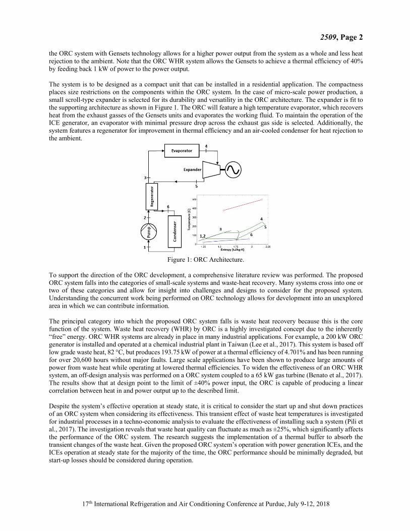
The system is to be designed as a compact unit that can be installed in a residential application. The compactness places size restrictions on the components within the ORC system. In the case of micro-scale power production, a small scroll-type expander is selected for its durability and versatility in the ORC architecture. The expander is fit to the supporting architecture as shown in Figure 1. The ORC will feature a high temperature evaporator, which recovers heat from the exhaust gasses of the Gensets units and evaporates the working fluid. To maintain the operation of the ICE generator, an evaporator with minimal pressure drop across the exhaust gas side is selected. Additionally, the system features a regenerator for improvement in thermal efficiency and an air-cooled condenser for heat rejection to the ambient.
Figure 1: ORC Architecture.
To support the direction of the ORC development, a comprehensive literature review was performed. The proposed ORC system falls into the categories of small-scale systems and waste-heat recovery. Many systems cross into one or two of these categories and allow for insight into challenges and designs to consider for the proposed system. Understanding the concurrent work being performed on ORC technology allows for development into an unexplored area in which we can contribute information. The principal category into which the proposed ORC system falls is waste heat recovery because this is the core function of the system. Waste heat recovery (WHR) by ORC is a highly investigated concept due to the inherently “free” energy. ORC WHR systems are already in place in many industrial applications. For example, a 200 kW ORC generator is installed and operated at a chemical industrial plant in Taiwan (Lee et al., 2017). This system is based off low grade waste heat, 82 °C, but produces 193.75 kW of power at a thermal efficiency of 4.701% and has been running for over 20,600 hours without major faults. Large scale applications have been shown to produce large amounts of power from waste heat while operating at lowered thermal efficiencies. To widen the effectiveness of an ORC WHR system, an off-design analysis was performed on a ORC system coupled to a 65 kW gas turbine (Benato et al., 2017). The results show that at design point to the limit of ±40% power input, the ORC is capable of producing a linear correlation between heat in and power output up to the described limit. Despite the system’s effective operation at steady state, it is critical to consider the start up and shut down practices of an ORC system when considering its effectiveness. This transient effect of waste heat temperatures is investigated for industrial processes in a techno-economic analysis to evaluate the effectiveness of installing such a system (Pili et al., 2017). The investigation reveals that waste heat quality can fluctuate as much as ±25%, which significantly affects the performance of the ORC system. The research suggests the implementation of a thermal buffer to absorb the transient changes of the waste heat. Given the proposed ORC system’s operation with power generation ICEs, and the ICEs operation at steady state for the majority of the time, the ORC performance should be minimally degraded, but start-up losses should be considered during operation.

2509, Page 3
17th International Refrigeration and Air Conditioning Conference at Purdue, July 9-12, 2018
The proposed ORC system also falls into the category of small-scale ORC systems because of the unique challenges that arise due to the cycle sizing. For example, an investigation of a small-scale, low-grade 1.2 kW ORC using a piston-reciprocating expander reveals that small-scale systems are very susceptible to performance fall off (Bianchi et al., 2017). This presents caution to the ORC design and suggest minimizing the superheating of the system. However, the diminishing work output is a characteristic of the working fluid. An optimization of a small-scale ORC with R1233zd(E) presents that the isobaric lines of R1233d(E) allow for higher work output when highly superheated (Lavernia et al., 2017). This characteristic can be exploited in the proposed ORC system, but the limitations with R245fa and R134a should also be considered. An additional consideration for small-scale ORC systems is the comparatively large size of inefficiencies that limit thermal efficiency. A research study featuring a small-scale rotary vane expander within the design of three small-scale ORC systems, from 1.1-6.5 kW, reports that the smaller ORC systems suffer from the fact that the mechanical inefficiencies are larger in comparison to the work output (Masuch et al., 2017). The investigation finds that system with the requirement of outputting 2 kW should be sized at 150% of the design power output to compensate for the losses the small-scale system experiences. Following this concept, the ORC considered in this study is sized at 1.5 kW to overcome these inherent losses. This analysis supports the design choices for the ORC system and highlights the importance of the balance between the high superheating in the evaporator to minimize exergy loss while still maintaining power output. As shown above, WHR systems using ORC technology are a widely researched area with many publications and organizations revolving around them. Therefore, it is important to define the objectives of this research to expand the knowledge base. First, the proposed ORC system has a significantly different application than most WHR systems: ICE exhaust heat recovery. By applying the ORC technology to high-grade waste heat, the bounds of ORC technology are stretched to the limits. This research investigates if the technology can still function at high enough efficiencies to be worth pushing temperatures to the upper limits. Second, the presented ORC experimentation investigates the use of various new components, such as a micro-tube boiler and a novel scroll pump, within the ORC system. High temperature input and large temperature differences across the evaporator increase heat transfer rates and allow for a more compact heat exchanger design. The research of high temperature applications with sub-critical ORC architecture has the potential to open new avenues for ORC design and application.
2. System Modeling
Once the cycle design was completed, a detailed performance model was built in EES to better represent the expected ORC system performance for various heat input rates. The detailed performance model was developed using the following assumptions but instead of defining the ORC state points the model uses physical parameters from the components to solve for the state points. First, all modeling was performed at steady-state operation. Considering that the operation of the final ORC system will be on stationary power generation units, a steady state assumption is realistic. Second, all flow regimes are considered to be one-dimensional and maintain uniform properties throughout the processes. Third, for modeling simplification, pressure drops in heat exchangers were selected as finite amounts based on values found in the literature. This assumption eliminated the need to iterate on pressures at state points and simplified the modeling with minimal error introduced as a result. Pressure losses within the piping are not considered due to their short line lengths. The “floating point” method of solving for the ORC state points utilizes the EES built-in iterative solver to converge on a solution. Additionally, a semi-empirical expander model is adopted that calculates expander power output, isentropic efficiency, and over or under expansion processes. The model uses an assumed mechanical efficiency, supplied intermediate pressure, and the internal volume ratio to define two separate processes within the expander. The first process is assumed to occur as an isentropic expansion to the volume ratio of the expander. The second process occurs at constant volume and accounts for any over or under expansion processes. The equations used to model these processes are shown below, Equations (1) - (5).
��#$%,'() = ��#$%,'()𝑤#$%,'() (1) 𝑤#$%,'() = -ℎ#$,'() − ℎ#$%0 + 𝑣#$%-𝑝#$% − 𝑝45%,'()0 (2)
𝑣#$% = 𝒓𝑽,𝒃𝒖𝒊𝒍𝒕=𝒊𝒏𝑣#$,'() (3) ��?@AB%,'() = ��#$%,'()𝜂D'E@,'() (4)
𝜂#?,'() =FGHIJK,LMN=OIPQ
DRSK,LMN-@RS,LMN=@TUK,RG,LMN0 (5)

2509, Page 4
17th International Refrigeration and Air Conditioning Conference at Purdue, July 9-12, 2018
The floating-point method combined with the semi-empirical expander model allows the model to predict cycle state points for varying heat input rates and calculate the expected performance as a result. Given the calculated amounts of waste heat from each of the selected ICE generators, it was then possible to use the detailed ORC model to predict the system performance with each of the units. The predicted performances of the ORC system are listed in Table 1 along with the controlled parameters that facilitate that performance. The simulation results show that the ORC thermal efficiency remains relatively unchanged across the range of possible ICE generators. This indicates reliable power output at the designed operating points. However, the second law efficiency is significantly higher for gasoline engines compared to the diesel engines. The higher exhaust temperature allows for higher heat transfer rates in the evaporator at these design points allowing for better heat recovery. The detailed model predictions signify that the effectiveness of the ORC system is large enough to warrant movement to system development and experimental testing.
Table 1: Detailed ORC Simulation Performance Results with ICE Generators.
S.No. Engine Mfr.
Model Exhaust Temperature
Exhaust Mass Flow Rate
Working Fluid Mass Flow Rate
Expander Work Output
Cycle Thermal Efficiency
Second Law Efficiency
[°C] [g/s] [g/s] [KW] [%] [%]
1 Yanmar 2TNV70 401.6 35.5 30 1.089 11.15 6.99
2 Yanmar 3TNV70 399.2 51.9 45 1.578 11.28 7.12
3 Yanmar 3TNE-68 363.7 47.4 32 1.185 10.98 6.54
4 Subaru EH63D 758.5 20.3 42 1.447 11.11 8.27
5 Subaru EH65D 660.4 20.3 40 1.272 11.49 8.4
6 Kubota Z602-E3B 356.3 37.3 27.5 0.9402 11.01 6.74
7 Kubota D722 372.7 43.4 35 1.182 11.06 6.93
4. Experimental Test Stand To begin the development process of the modeled ORC system, an experimental test stand capable of component evaluation and performance analysis was designed. The test stand is required to operate an ORC at full scale heat input and evaluate each component individually as well as the overall cycle. Given the specifications for the heat exchangers, pump, and expander obtained from system modeling, several supporting systems are required to operate the cycle. Various photos of the test stand are shown in Figure 2. The front of the test stand is shown with all of the control modules that are used in operating the test stand. Also shown is the upper table layout of the test stand with the expander, evaporator, and heating element as well as the required piping and ducting.

2509, Page 5
17th International Refrigeration and Air Conditioning Conference at Purdue, July 9-12, 2018
Figure 2: Existing Experimental Test Stand (Front View, Top View).
The test stand is equipped with various control systems in order to operate the ORC at desired conditions. The first control unit, shown in Figure 3, and is a PID controller for the heating element supplying the hot air to the evaporator. The controller operates the heating coils based on a measured process temperature at the outlet of the heater. By providing a desired process temperature, the controller maintains the flow temperature within ±2 °C. The next control unit is the variable frequency drive (VFD) for the generator which allows control of the rotational speed of the generator. Input is given in Hz and is maintained within the manufacturer’s specification of ±0.05 Hz. A second VFD is required for controlling the rotational speed of the motor powering the prototype scroll pump. This VFD operates similarly to the generator VFD but has a lower precision of ±0.1 Hz. Finally, a variable speed fan is used to provide airflow across the condenser and is controlled by an external potentiometer. The potentiometer provides control over the fan speed, but due to the associated fan curve, the resolution of the control is at worst ±0.1415 m3/min. These systems comprise the basic controls that make the operation of the ORC possible. A purpose-built prototype Oldham Ring style scroll expander was evaluated on the test stand. The specifications for the scrolls are detailed in Table 2. The Oldham ring expander used on the experimental test stand was built using mild-spec steel and weighs approximately 20 kg. The expander features an inlet and outlet port on the front face of the expander and is constructed with a magnetic coupling to maintain semi-hermetic operation. The magnetic coupling is housed in an aluminum canister, which supports the output shaft. The Oldham ring expander is shown in Figure 3. The internal mechanical components from the tested Oldham ring expander are also shown in Figure 3, where the stator scroll is on the left and the orbiting scroll is on the right with the Oldham ring, made of aluminum, placed on top.
Figure 3: Oldham Ring Expander External View and Internal Components.
The micro-tube evaporator used in the experimental test stand, shown in Figure 4, is a prototype unit designed and built to fit the heat transfer characteristics required by the designed ORC cycle.

2509, Page 6
17th International Refrigeration and Air Conditioning Conference at Purdue, July 9-12, 2018
Figure 4: Prototype Micro-Tube Evaporator and Micro-Channel Condenser.
Two additional heat exchangers are used to complete the ORC system: a brazed plate regenerator, and a micro-channel condenser which is also shown in Figure 4. Each heat exchanger was designed for use in this particular ORC but are industry standard constructions. Lastly, a prototype scroll pump designed for this application is used on the test stand to provide pressure difference and mass flow. The scroll pump was designed and manufactured to meet the requirements of the designed ORC system, which is shown in Table 2.
Table 2: Scroll Machinery Design Parameters. Scroll Design Parameter Expander Pump Unit
Rotational Velocity 3600 3600 RPM Suction Volume 4.5 E-4 1.05 E-4 m3
Internal Volume Ratio 4.22 1 - Designed Power Output/Input 1.2 .128 kW
Scroll pumps are not commonly used in thermal systems due to their cost and complexity, but they are useful for this application since they can easily be matched to the expander. The scroll pump used on the test stand functions using the Oldham ring mechanism and is constructed out of aluminum with a steel face plate. The pump is driven using a magnetic coupling assembly similar to the expanders, but the casing is made of stainless steel. The stainless steel allows slippage between the rotors and induces Eddie losses, which are accounted for in data reduction. To evaluate expander performance, the power output, isentropic efficiency and filling factor of the expander must be calculated. To calculate the power output from the expander, the rotary torque sensor output is used in conjunction with the controlled expander rotational speed. The power output is then converted to kilowatts by a constant conversion factor. The shaft output power is calculated as:
��'() =VWXLMN∗ZLMN
[\.^_abcd∗RSeQfg h
(6)
Using the calculated power output, it is possible to determine the isentropic efficiency of the expander using the previously calculated expander inlet state point and an assumed isentropic process state point.
𝜂'(),#? = FLMN
DiLJ-@RS=@TUK,RG0 (7)
To evaluate the volumetric performance of the expander, the filling factor is calculated using the inlet state point of the expander and the measured mass flow rate. The inlet conditions allow for the calculation of working fluid density which combined with mass flow rate and expander rotational speed gives the expander filling factor:
𝐹𝐹'() =DiLJ
kRSlGUmbcdLMNnoa GLmPRSh
(8)
2509, Page 7
17th International Refrigeration and Air Conditioning Conference at Purdue, July 9-12, 2018
Similar calculations are made for both the regenerator and the condenser. However, for the evaporator and the condenser, it is necessary to calculate the mass flow rate of the air flowing across them. For the condenser, the variable speed fan curves are used to interpolate the volumetric flow of the air. The evaporator uses the compressed airflow sensor to measure volumetric flow rates as well. The conversion of air volumetric flow to mass flow requires the measurement of ambient temperature and relative humidity which allow for the determination of density. Using the volumetric flow and density, it is possible to calculate the mass flow of air as shown:
��A#p = 𝜌A#p,EArE��A#p,D'A? (9) Finally, the system performance is evaluated by calculating: cycle thermal efficiency and system second law efficiency. Cycle thermal efficiency is determined using the previously calculated evaporator heat transfer rate and the calculated net power output. The efficiency calculation is performed as shown:
𝜂EtE,u?% = FSLKOLvIN
(10)
The second law efficiency is calculated by dividing the power output over the maximum possible heat transfer available from the heated air. Similar to the effectiveness calculation for the evaporator, a dead state is assumed with the air cooled all the way down to ambient. Using this minimum state point, the second law efficiency is calculated as shown:
𝜂EtE,w$x = FSLK
DIRi-yIRi,RS=yIRi,zLIz0 (11)
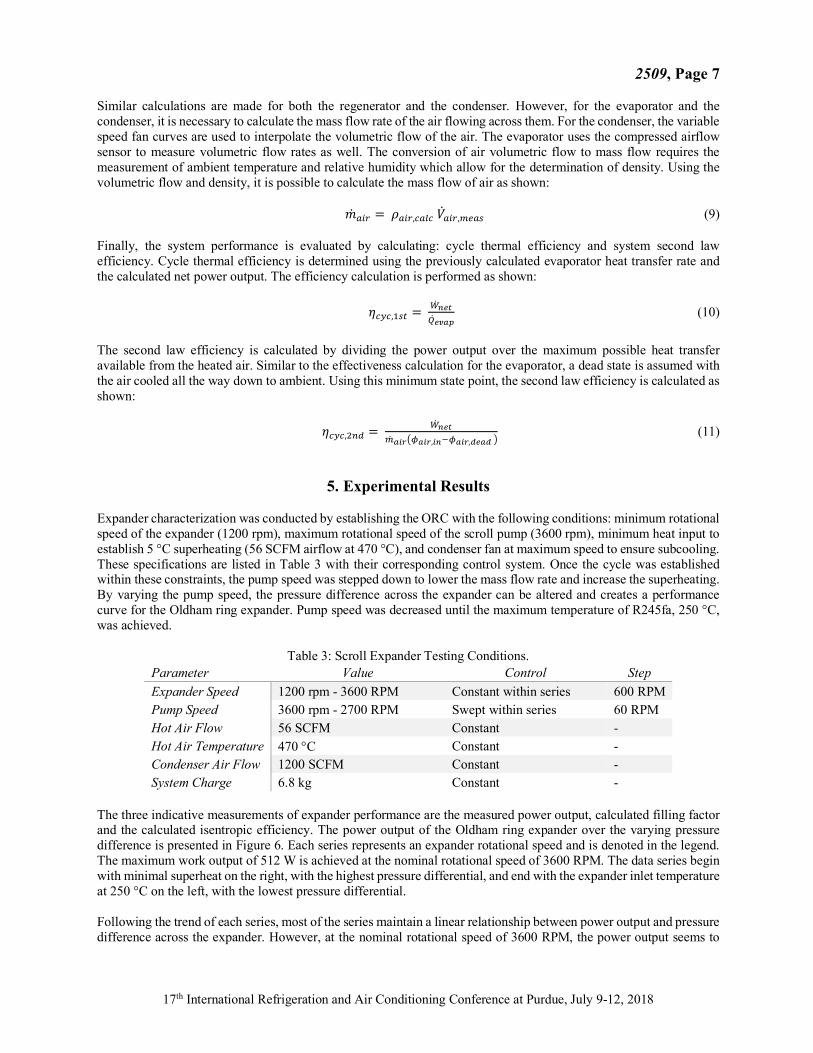
5. Experimental Results Expander characterization was conducted by establishing the ORC with the following conditions: minimum rotational speed of the expander (1200 rpm), maximum rotational speed of the scroll pump (3600 rpm), minimum heat input to establish 5 °C superheating (56 SCFM airflow at 470 °C), and condenser fan at maximum speed to ensure subcooling. These specifications are listed in Table 3 with their corresponding control system. Once the cycle was established within these constraints, the pump speed was stepped down to lower the mass flow rate and increase the superheating. By varying the pump speed, the pressure difference across the expander can be altered and creates a performance curve for the Oldham ring expander. Pump speed was decreased until the maximum temperature of R245fa, 250 °C, was achieved.
Table 3: Scroll Expander Testing Conditions. Parameter Value Control Step Expander Speed 1200 rpm - 3600 RPM Constant within series 600 RPM Pump Speed 3600 rpm - 2700 RPM Swept within series 60 RPM Hot Air Flow 56 SCFM Constant - Hot Air Temperature 470 °C Constant - Condenser Air Flow 1200 SCFM Constant - System Charge 6.8 kg Constant -
The three indicative measurements of expander performance are the measured power output, calculated filling factor and the calculated isentropic efficiency. The power output of the Oldham ring expander over the varying pressure difference is presented in Figure 6. Each series represents an expander rotational speed and is denoted in the legend. The maximum work output of 512 W is achieved at the nominal rotational speed of 3600 RPM. The data series begin with minimal superheat on the right, with the highest pressure differential, and end with the expander inlet temperature at 250 °C on the left, with the lowest pressure differential. Following the trend of each series, most of the series maintain a linear relationship between power output and pressure difference across the expander. However, at the nominal rotational speed of 3600 RPM, the power output seems to

2509, Page 8
17th International Refrigeration and Air Conditioning Conference at Purdue, July 9-12, 2018
have reached the maximum and is in decline at higher pressure differentials. This would suggest that the power output of the system would benefit marginally from increasing the pressure difference across the expander. However, the 3000 RPM trend suggests that further increasing the pressure differential at that rotational speed would create higher power output potential. Further investigation with a modified or upgraded liquid pump would help define the trends experienced in the extrapolated areas. The isentropic efficiencies achieved by the Oldham ring expander show a similar trend to the power output data. The isentropic efficiencies of the Oldham ring expander are also presented in Figure 5, where they are compared across varying pressure ratios. The isentropic efficiencies appear to remain constant for the expander rotational velocities of 1200-3000 RPM. However, the nominal operating rotational speed presents efficiency drop off as the pressure ratio rises above 5.5. Given that the expander is constructed with an internal volume ratio of 4.22, it would appear that the gas is exiting the expander under-expanded at higher pressure ratios, which decreases the isentropic efficiency of the expansion process.
Figure 5: Oldham Ring Expander Performance Measurements.
While the isentropic efficiencies achieved by the Oldham ring expander of 32-45% for the nominal rotational speed are lower than the expected 60%, there is still indication of promise for improvement. The performance of the expander at the lower inlet pressures of ~14 bar suggest that the expander could output much higher power with an improved liquid pumping system and therefore, achieve higher isentropic efficiencies. Given the objective of increasing the ORC system’s second law efficiency, power output per unit of heat available, and using a constant heat input, it would seem that increasing the superheat of the system has enough of a negative effect on the power output of the ORC that it may not be beneficial to increase superheat to minimize heat transfer losses. Power output of the expander in Figure 5.10 and isentropic efficiency in Figure 5 show the best performance with minimal superheating. This effect should be considered in the ORC system design and with further analysis, cycle changes should be implemented. The Oldham ring expander’s volumetric efficiency is presented in Figure 6 where the filling factor is shown. Each expander speed has a range of data points, which correspond to the range of pump speeds, and the filling factor varies because of it. The highest filling factor in the spread occurs at the highest pump speed and the lowest filling factor at the slowest pump speed. The downward trend of filling factor as the expander rotational speed decreases is to be expected as the swept volume rate of the expander fails to match the flow created by the pump. However, the filling factor asymptotically reaches a minimum of approximately 1.5 as the expander swept volume rate matches the delivered mass-flow rate.
0
0.1
0.2
0.3
0.4
0.5
0.6
9 9.5 10 10.5 11 11.5 12 12.5 13
Pow
er O
utpu
t [kW
]
Pressure Difference [bar]
1200 RPM1800 RPM2400 RPM3000 RPM3600 RPM
0
0.1
0.2
0.3
0.4
0.5
4.5 5 5.5 6 6.5 7
Expa
nder
Isen
trop
ic E
ffici
ency
[-]
Pressure Ratio [-]
1200 RPM1800 RPM2400 RPM3000 RPM3600 RPM

2509, Page 9
17th International Refrigeration and Air Conditioning Conference at Purdue, July 9-12, 2018
Figure 6: Oldham Ring Expander Filling Factors.
The filling factor of the Oldham ring expander presents significantly improved operation as the expander moves towards the designed rotational speed of 3600 RPM. However, filling factors of 1.5-2 still indicate that there is a large amount of leakage occurring in the Oldham ring expander. Clearances and gaps between the scroll wraps are under consideration as a result and should be improved in the next generation of expanders. The experimental results from the expander testing are tabulated in Table 5 along with other highlighted performance characteristics of the system. It should be noted that these data entries are taken from full sweeps and each point only represents the condition at which the expander was outputting the most power.
Table 4: Oldham Ring Expander Testing Results Summary.
Exp
ande
r R
otat
iona
l Spe
ed
Pum
p R
otat
iona
l Sp
eed
Pres
sure
Rat
io
Exp
ande
r Pr
essu
re
Diff
eren
ce
Exp
ande
r Po
wer
O
utpu
t
Exp
ande
r Is
entr
opic
E
ffic
ienc
y
Filli
ng F
acto
r
Cyc
le E
ffici
ency
Seco
nd L
aw
Eff
icie
ncy
Pum
p Po
wer
In
put
Hig
h Si
de
Pres
sure
Dro
p
Eva
pora
tor
Eff
ectiv
enes
s
[RPM] [RPM] [-] [bar] [kW] [%] [-] [%] [%] [kW] [bar] [%] 1800 2940 6.15 10.82 0.2332 19.3% 3.111 3.24% 1.71% 0.112 0.34 58.25% 2400 3360 5.025 10.89 0.3682 31.6% 2.622 4.86% 2.70% 0.116 0.53 58.04% 3000 3300 5.101 10.86 0.4449 34.6% 2.279 5.34% 3.27% 0.127 0.50 64.32% 3600 3300 5.272 11.18 0.5120 41.9% 1.740 6.49% 3.67% 0.123 0.45 59.06%
6. Conclusions
Waste heat recovery (WHR) from generators for small electrical and thermal systems could provide the high efficiency energy generation solution to meet the intermittency of renewable energy sources. A WHR system utilizing ORC technology is presented as a bottoming cycle in Gensets exhaust gas streams. The ORC system is designed for the novel operation of use with high temperature exhaust gases and requires several prototype components for successful implementation. The combination of novel micro-tube evaporator, a small-scale scroll expander, and scroll pump with the other necessary supporting systems presents a unique opportunity for system development. To assist in developing a commercially viable ORC WHR unit, an experimental test stand was developed to test the novel components and system performance. Each component is evaluated individually allowing for insight into operation and improvements on a component level. Focus is given to the characterization of the scroll expanders due to their critical function in producing the power for the ORC. The Oldham ring expander represents the industry standard for scroll devices and produces the most power output of 512 W from a constant heat source of 7722 W. The spinning scroll represents a novel approach to scroll expansion devices and operates at a higher isentropic efficiency of 46% than the Oldham ring expander at 43%. It should be noted that the performance of the prototype expander was
0
1
2
3
4
5
6
1000 1500 2000 2500 3000 3500
Filli
ng F
acto
r
Expander Rotational Speed [RPM]

2509, Page 10
17th International Refrigeration and Air Conditioning Conference at Purdue, July 9-12, 2018
negatively impacted by the use of a prototype scroll pump. The scroll pump provided limitations on the reachable pressure differences across the expanders inside the system and limited the characterization range of the expanders. Despite this, the Oldham ring expander’s performance in this ORC suggests strong potential of the ORCs as a waste heat recovery system for small-scale high-grade waste heat streams.
NOMENCLATURE
𝐹𝐹 – Filling Factor [-] 𝑤 - Specific Work [kJ/kg] 𝑎𝑖𝑟 - Air 𝑀𝑒𝑎𝑠 - Measured ℎ - Specific Enthalpy [kJ/kg] �� – Power [kW] 𝐶𝑎𝑙𝑐 – Calculated 𝑚𝑒𝑐ℎ - Mechanical �� – Mass Flow Rate [kg/s] 𝜂 – Efficiency [-] 𝑐𝑦𝑐 - Cycle 𝑚𝑖𝑛 - Minimum �� – Heat Transfer Rate [W] 𝜖 – Effectiveness [-] 𝐸𝑣𝑎𝑝 - Evaporator 𝑛𝑒𝑡 – Combined In/Out 𝑅𝑃𝑀 – Rotational Speed 𝜌 – Density [kg/m3] 𝑒𝑥𝑝 - Expander 𝑠ℎ𝑎𝑓𝑡 – Shaft 𝑟l,�5#r%=#$ – Volume Ratio [-] 𝜏 – Torque [N-m] 𝐻𝑋 – Heat Exchanger 1𝑠𝑡 – First Law 𝑣 – Specific Volume [m3/kg] 𝑖𝑛𝑡 – Intermediate State 2𝑛𝑑 – Second Law 𝑉 – Volume [m3] 𝑖𝑠 – Isentropic
REFERENCES Benato, A., Stoppato, A., Mirandola, A., & Medico, M. D. (2017). Design and Off-Design Analysis of an ORC
Coupled with a Micro-Gas Turbine. Energy Procedia,129, 551-558. Bianchi, M., Branchini, L., Pascale, A. D., Orlandini, V., Ottaviano, S., Pinelli, M., . . . Suman, A. (2017).
Experimental Performance of a Micro-ORC Energy System for Low Grade Heat Recovery. Energy Procedia,129, 899-906.
Lavernia, A., Ziviani, D., Shaffer, B., Bansal, K., & Groll, E. A. (2017). Optimization of an organic Rankine cycle as bottoming cycle of a 1 kWe GENSET for residential applications. Energy Procedia,129, 867-874.
Lee, Y., Liu, L., Chang, Y., & Hsieh, J. (2017). Development and application of a 200 kW ORC generator system for energy recovery in chemical processes. Energy Procedia,129, 519-526. doi:10.1016/j.egypro.2017.09.176
Mascuch, J., Novotny, V., Vodicka, V., & Zeleny, Z. (2017). Towards development of 1-10 kW pilot ORC units operating with hexamethyldisiloxane and using rotary vane expander. Energy Procedia,129, 826-833.
Pili, R., Romagnoli, A., Spliethoff, H., & Wieland, C. (2017). Techno-Economic Analysis of Waste Heat Recovery with ORC from Fluctuating Industrial Sources. Energy Procedia,129, 503-510.
Suman, A., Randi, S., Casari, N., Pinelli, M., & Nespoli, L. (2017). Experimental and Numerical Characterization of an Oil-Free Scroll Expander. Energy Procedia,129, 403-410.
ACKNOWLEDGEMENT
The authors would like to acknowledge ARPA-E’s GENSETS program for their continued support of this research endeavor. The authors would also like to thank the Herrick Laboratories staff and shop for their support in constructing and maintaining the experimental test stand.