development of civil engineering design skills through
TRANSCRIPT

Proceedings of the 5th International CDIO Conference, Singapore Polytechnic, Singapore, June 7 - 10, 2009
DEVELOPMENT OF CIVIL ENGINEERING DESIGN SKILLS THROUGH ACTIVE LEARNING
Prof. Steve Millard
University of Liverpool, Liverpool, UK
Dr Stephen W Jones
University of Liverpool, Liverpool, UK
ABSTRACT In 2008, the Department of Engineering at the University of Liverpool launched the Liverpool Engineer initiative, which comprises an educational framework incorporating the principles of CDIO to develop multi-faceted engineers ready to meet the professional needs of the 21st century. Active learning is at the core of the Liverpool Engineer learning and teaching philosophy. For Civil Engineering students, the development of open-minded design skills is fostered through a series of three progressive Design-Build-Test projects, introduced in the first year of their academic studies. Students work in their tutorial groups (typically six students) to develop a series of model cardboard bridges, which are designed to carry realistic serviceability and ultimate loads with acceptable deflection and without collapse, respectively. The new Active Learning Laboratory was completed in 2008 and provides an ideal environment and facility for these projects, with an overall capacity for 280 engineering students (all disciplines). The structured progression of the bridge design projects allows students to experiment with and explore the properties of tension and compression members fabricated from cardboard. Their findings are compared with the anticipated loads in the members (derived using computer structural analyses with user-friendly graphics and animation) to allow them to develop a complete bridge structure and to make an assessment of its factor of safety. The truss geometry and member properties of the first „Icebreaker‟ bridge are tightly constrained. For the second and third bridges, the student groups have an increasing degree of freedom to develop their own concepts and structural solutions to the problem. The paper will focus on the student experience and will discuss some problems and pitfalls encountered with their understanding of structural behaviour. Keywords Bridge, build, analyse, test, stability, strength, design INTRODUCTION The Department of Civil Engineering at the University of Liverpool merged with the Department of Engineering in 2006 to form a more coherent and integrated Department of Engineering. Emerging from this integration was the adoption of CDIO learning and teaching principles across all the engineering disciplines. In 2008 Liverpool Engineer initiative was launched, incorporating the principles of CDIO, to develop multifaceted engineers ready to meet the professional needs of the 21st century. This initiative coincided with the completion of a major building development at the University known as the Active Learning laboratory. This laboratory comprises a brand new state-of-the-art teaching facility that can accommodate all 280 engineering first year students, using purpose-built work benches. There is audio-visual equipment to allow academic staff to speak simultaneously to the entire student cohort on two floors, when required for announcements or introductory talks.

Proceedings of the 5th International CDIO Conference, Singapore Polytechnic, Singapore, June 7 - 10, 2009
For Civil Engineering students, the development of open-minded design skills is fostered through a series of three progressive Design-Build-Test projects, introduced in the first year of their academic studies. This is a significant departure from the traditional introduction to a Civil Engineering degree programme, which would typically concentrate on the introduction of engineering science principles but with very little practical design experience in the first, and often the second years. The traditional approach was very successful in developing engineering analysts, but the outcome of these courses was often that students lacked practical skills, an understanding of structural behaviour or the ability to apply engineering judgement. These aspects were often left to be developed later in their careers, when working in practice. CDIO principles, incorporating active learning, have been adopted to bring forward the development of these more practical design skills. Students will graduate with a better appreciation of the relationship between engineering principles and practical design and more ready to face the challenges of a professional engineering career. The first project, known as the „Icebreaker‟ takes place over four afternoons in the very first week of the academic year when students first arrive at the University. Students work in their tutorial groups (typically six students), which presents an ideal opportunity to get to know their fellow tutees and to start working as a team at the start of their University life. This initial project is followed by two further progressive projects, which build on the skills learned (or not in some cases) during the Icebreaker project. Students develop skills of structural member selection and the design of structural form. All three projects are based on exercises developed by Stephen J Ressler at the United States Military Academy [1]. The exercises have been now been run for the last three years at the University of Liverpool. A number of developments have been introduced to improve the student experience. However, the main principles of the project remain faithful to the original concepts. In this paper the three progressive stages of the projects will be described. Key learning points will be highlighted and some of the typical problems encountered by the students are described WEEK 1 – THE ‘ICEBREAKER’ The Icebreaker project takes place during the afternoons of Monday, Tuesday, Thursday and Friday of the students' first week of their engineering degree programmes. All engineering disciplines participate in the same project, comprising Civil Engineering, Mechanical Engineering, Aerospace Engineering and Manufacturing Engineering students. At the start of each session the students are given a set of the briefing notes and a brief introductory talk. The project involves the building and testing of a simple single-span truss bridge made from cardboard cut from standard manila file folders. This material was chosen because it is cheap, readily available and provides a surprisingly good and repeatable structural behaviour. The project comprises a build and test exercise to a predetermined or constrained design. The geometry, sections and static loads are all provided and there is no opportunity provided for modifying the design. Principal tasks of the ‘Icebreaker’ Project Students work in groups of six (typically their tutor groups). A series of tasks (see Figure 1) were set to guide students through the component testing, analysis, fabrication and overall structural loading of a model cardboard bridge. The first task is to fabricate a set of tension and compression members to dimensions given in the briefing notes (see Figure 2).
Proceedings of the 5th International CDIO Conference, Singapore Polytechnic, Singapore, June 7 - 10, 2009
Fabricate tension strips, strengthen ends
Fabricate compression tubes, strengthen ends
Test to failure tension and compression components
Analyse bridge structure to determine component forces
Determine component factor of safety and overall FoS
Fabricate tension and compression components for bridge
Fabricate gusset plate joints
Assemble bridge
Load bridge to serviceability and ultimate limit states
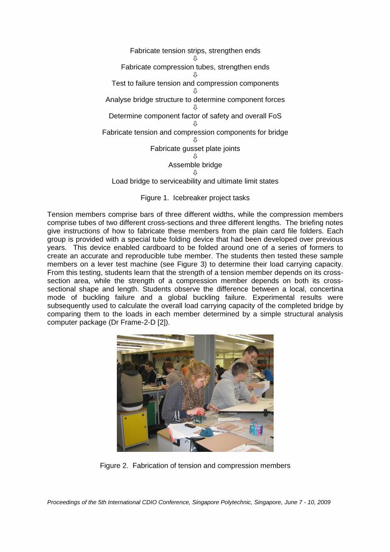
Figure 1. Icebreaker project tasks Tension members comprise bars of three different widths, while the compression members comprise tubes of two different cross-sections and three different lengths. The briefing notes give instructions of how to fabricate these members from the plain card file folders. Each group is provided with a special tube folding device that had been developed over previous years. This device enabled cardboard to be folded around one of a series of formers to create an accurate and reproducible tube member. The students then tested these sample members on a lever test machine (see Figure 3) to determine their load carrying capacity. From this testing, students learn that the strength of a tension member depends on its cross-section area, while the strength of a compression member depends on both its cross-sectional shape and length. Students observe the difference between a local, concertina mode of buckling failure and a global buckling failure. Experimental results were subsequently used to calculate the overall load carrying capacity of the completed bridge by comparing them to the loads in each member determined by a simple structural analysis computer package (Dr Frame-2-D [2]).
Figure 2. Fabrication of tension and compression members
Proceedings of the 5th International CDIO Conference, Singapore Polytechnic, Singapore, June 7 - 10, 2009
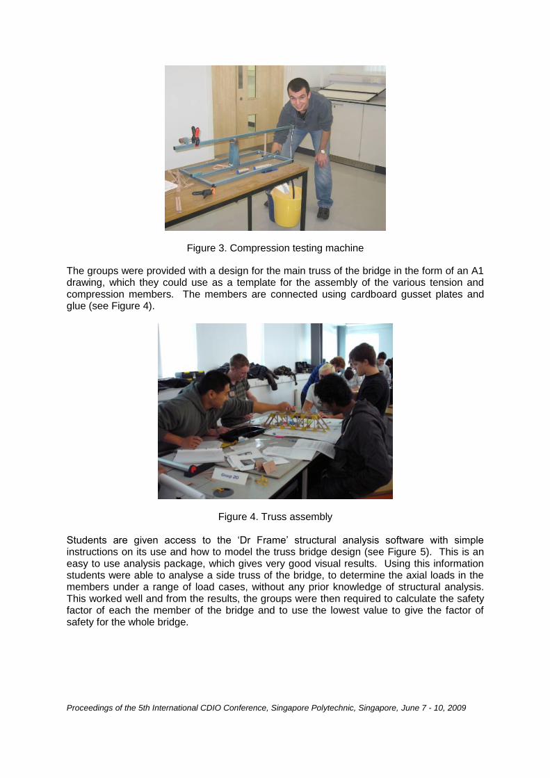
Figure 3. Compression testing machine
The groups were provided with a design for the main truss of the bridge in the form of an A1 drawing, which they could use as a template for the assembly of the various tension and compression members. The members are connected using cardboard gusset plates and glue (see Figure 4).
Figure 4. Truss assembly
Students are given access to the „Dr Frame‟ structural analysis software with simple instructions on its use and how to model the truss bridge design (see Figure 5). This is an easy to use analysis package, which gives very good visual results. Using this information students were able to analyse a side truss of the bridge, to determine the axial loads in the members under a range of load cases, without any prior knowledge of structural analysis. This worked well and from the results, the groups were then required to calculate the safety factor of each the member of the bridge and to use the lowest value to give the factor of safety for the whole bridge.

Proceedings of the 5th International CDIO Conference, Singapore Polytechnic, Singapore, June 7 - 10, 2009
Figure 5. Dr Frame structural analysis The groups were required to plan and to divide up the tasks (member fabrication, testing, analysis and assembly) to build the bridge within the allotted time ready for a showpiece testing session on the Friday afternoon. The project was designed as an introductory exercise to develop a range of important personal and professional skills. Students were motivated by the practical aspects of the project, clear goals and working in a team and being treated as professional engineers. Some problems encountered during the ‘Icebreaker’ There were a few problems with the use of the tube folder. Clear step-by-step instructions were provided on how to use the tube folder. However, they were not always read carefully, sometimes resulting in badly made seams on tubes and twisted sections. When assembling the main side trusses, some groups did not follow the instructions to use a piece of tracing paper over the drawing during the glueing procedure. This caused the fabricated members to be stuck to the drawing and made it much more difficult to lift up the assembled truss without damaging it. Each group was provided with a quality guillotine for cutting out cardboard members. There were also a few safety issues with students choosing instead to use scissors and the shape knife provided for cutting out the members. A number of the groups omitted the strengthening collars recommended for the ends of the compression member test elements. This lead to a premature local failure of the tube ends and consequently the section strength was under-estimated. In addition tensile tests were sometimes carried out on the wrong sized bars. Occasionally, there was some confusion over whether a member was being tested in compression or tension due to arrangement of the lever-testing machine. There were examples where excess gravel ballast was suddenly dumped into the loading bucket at the often sudden point of failure. The tension/compression test machine incorporated a steel retaining stay, which allowed the lever arm to be firmly propped while delicate cardboard test members were positioned and restrained. Some groups even proceeded with tests while the retaining stay was still in place, indicating that they were not always thinking or questioning the reality of the test they were undertaking. Not all of the plotted results of the compression members (load capacity v length) were the correct shape. Some plotted results curved upwards instead of downwards, indicating an increase in compressive strength with member length.

Proceedings of the 5th International CDIO Conference, Singapore Polytechnic, Singapore, June 7 - 10, 2009
However, the one issue that caused the greatest confusion was the re-occurring of the factor of 2 in calculating the factor of safety. First, the testing machine included a mechanical advantage of 2 between the applied load and the test piece (see Figure 3). Some groups failed to realise that the strength of the member was twice the load of the applied ballast at failure. Second, more than one group forgot that the analysis related just to one of the two trusses in the bridge and consequently over-estimated the loads in the members by a factor of two. Finally, there were a number of examples where students did not take account that tension members were made from two parallel flat bars on each side of the truss and that the total tensile load in the truss member was to be shared between the two bars. Testing of bridges at the end of the ‘Icebreaker’ On the Friday afternoon there was a ceremonial testing of all bridges in front of all of the Civil Engineering groups (see Figure 6). All groups completed their bridge models and presented them for testing along with a calculated factor of safety and an assessment of the critical truss member. Not all of these factors of safety were within the expected tolerance of the anticipated factor of safety of 2.1.
Figure 6. Icebreaker ceremonial testing Most bridges carried their design load of 5kg (representing serviceability limit state) and many carried the added overload of 3kg (representing ultimate limit state) successfully. Where they did not, the most common cause of failure was in the tension members located at the bottom of the truss. Where the parallel bars were of uneven length, it became obvious during loading that one was slack while the other was tight. This of course led to premature failure when the tight bar fails, carrying the entire load that had been assumed to be shared between two equal bars. WEEK 2 – TWO WEEK CREATION – PART 1 The second stage of the project is known as the Two Week Creation - Part 1. This takes place in the last week of Term 1 immediately before the Christmas break. The usual timetabled lectures were cancelled for the full 5 days. The project was again carried out in the Active Learning Laboratory.

Proceedings of the 5th International CDIO Conference, Singapore Polytechnic, Singapore, June 7 - 10, 2009
The project consisted of the construction of a second bridge. The main difference with the Icebreaker bridge was that they were given a different geometry – this time a Warren Deck truss with the structure below the deck level. In addition the design load for the second bridge was a more realistic rolling load travelling across the span rather than a static load placed at midspan. Students again analysed the structure using Dr Frame software to determined loads in all the members. They then used these results to select their own member sizes, based on the capacities they had measured during Icebreaker testing. However students were given access to a greater range of tube folder formers. This enabled the fabrication of a much greater range of compression tube sections. Students were instructed to determine by testing the strength of any new section size they wanted to use. This increase in choice of the compression member section enabled a significant optimisation in the design of the bridge to be carried out. Loading was carried out using a 6 kg weight with wheels, representing a rolling truck load, that was pulled across a hinged aluminium road track, sitting on the top chord of the truss, by a simple pulley system (see Figure 7). There was again a 3.8 kg overload that was tested with a second passage of the truck across the deck.
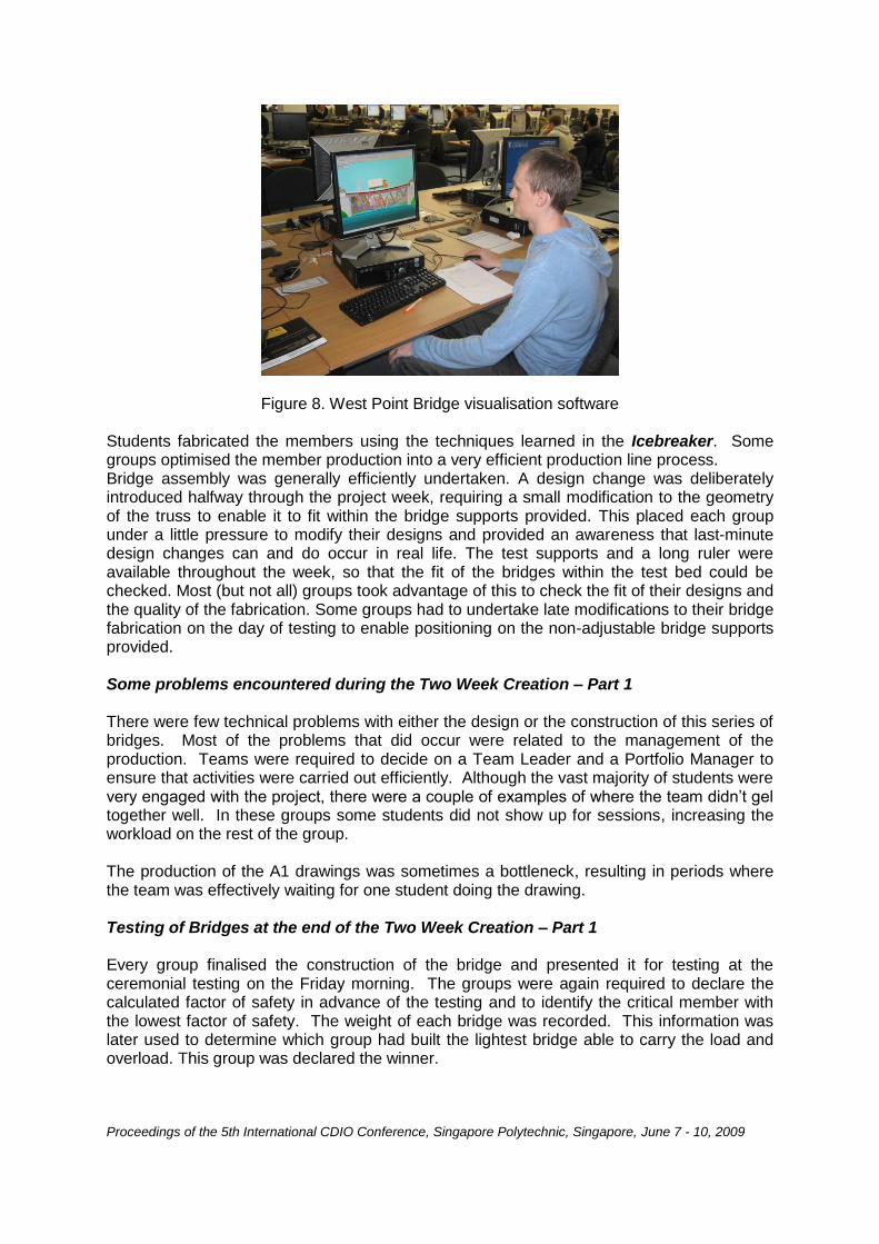
Figure 7. Two Week Creation Part 1 testing For this bridge truss fabrication the students produced their own drawings of the main trusses along with schedules of all the member sizes required. The drawings were needed as a template for the assembly of the bridge. In addition to the Dr Frame structural analysis, students were also required to use the West Point bridge visualisation software [3] (see Figure 8), which produced a structural model set in a visually realist setting of an urban river crossing. This software gave an exaggerated visual assessment of the deflected shape of the bridge under self weight and applied vehicle load. In addition under load the truss was coloured with a blue/red indication of tension or compression loading in each member of the truss. The software package also gave an immediate indication of the relative cost of any design choices or changes. Although the prices given were almost an order of magnitude less that realistic 2009 values and were quoted in US dollars, they did nevertheless give a useful indication of the relative cost efficiency of the designs.
Proceedings of the 5th International CDIO Conference, Singapore Polytechnic, Singapore, June 7 - 10, 2009
Figure 8. West Point Bridge visualisation software Students fabricated the members using the techniques learned in the Icebreaker. Some groups optimised the member production into a very efficient production line process. Bridge assembly was generally efficiently undertaken. A design change was deliberately introduced halfway through the project week, requiring a small modification to the geometry of the truss to enable it to fit within the bridge supports provided. This placed each group under a little pressure to modify their designs and provided an awareness that last-minute design changes can and do occur in real life. The test supports and a long ruler were available throughout the week, so that the fit of the bridges within the test bed could be checked. Most (but not all) groups took advantage of this to check the fit of their designs and the quality of the fabrication. Some groups had to undertake late modifications to their bridge fabrication on the day of testing to enable positioning on the non-adjustable bridge supports provided. Some problems encountered during the Two Week Creation – Part 1 There were few technical problems with either the design or the construction of this series of bridges. Most of the problems that did occur were related to the management of the production. Teams were required to decide on a Team Leader and a Portfolio Manager to ensure that activities were carried out efficiently. Although the vast majority of students were very engaged with the project, there were a couple of examples of where the team didn‟t gel together well. In these groups some students did not show up for sessions, increasing the workload on the rest of the group. The production of the A1 drawings was sometimes a bottleneck, resulting in periods where the team was effectively waiting for one student doing the drawing. Testing of Bridges at the end of the Two Week Creation – Part 1 Every group finalised the construction of the bridge and presented it for testing at the ceremonial testing on the Friday morning. The groups were again required to declare the calculated factor of safety in advance of the testing and to identify the critical member with the lowest factor of safety. The weight of each bridge was recorded. This information was later used to determine which group had built the lightest bridge able to carry the load and overload. This group was declared the winner.
Proceedings of the 5th International CDIO Conference, Singapore Polytechnic, Singapore, June 7 - 10, 2009
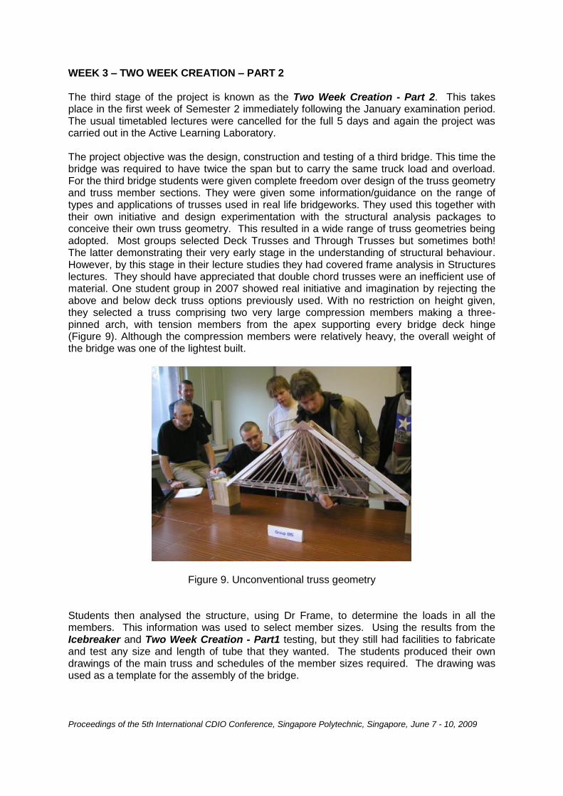
WEEK 3 – TWO WEEK CREATION – PART 2 The third stage of the project is known as the Two Week Creation - Part 2. This takes place in the first week of Semester 2 immediately following the January examination period. The usual timetabled lectures were cancelled for the full 5 days and again the project was carried out in the Active Learning Laboratory. The project objective was the design, construction and testing of a third bridge. This time the bridge was required to have twice the span but to carry the same truck load and overload. For the third bridge students were given complete freedom over design of the truss geometry and truss member sections. They were given some information/guidance on the range of types and applications of trusses used in real life bridgeworks. They used this together with their own initiative and design experimentation with the structural analysis packages to conceive their own truss geometry. This resulted in a wide range of truss geometries being adopted. Most groups selected Deck Trusses and Through Trusses but sometimes both! The latter demonstrating their very early stage in the understanding of structural behaviour. However, by this stage in their lecture studies they had covered frame analysis in Structures lectures. They should have appreciated that double chord trusses were an inefficient use of material. One student group in 2007 showed real initiative and imagination by rejecting the above and below deck truss options previously used. With no restriction on height given, they selected a truss comprising two very large compression members making a three-pinned arch, with tension members from the apex supporting every bridge deck hinge (Figure 9). Although the compression members were relatively heavy, the overall weight of the bridge was one of the lightest built.
Figure 9. Unconventional truss geometry
Students then analysed the structure, using Dr Frame, to determine the loads in all the members. This information was used to select member sizes. Using the results from the Icebreaker and Two Week Creation - Part1 testing, but they still had facilities to fabricate and test any size and length of tube that they wanted. The students produced their own drawings of the main truss and schedules of the member sizes required. The drawing was used as a template for the assembly of the bridge.

Proceedings of the 5th International CDIO Conference, Singapore Polytechnic, Singapore, June 7 - 10, 2009
By the time of this third week, groups were generally able to apply much better fabrication methods. All tubes were better made and the trusses were all offered up to the testing supports to eliminate any span fit problems. Some Problems Encountered during the Two Week Creation – Part 2 Every group finished the construction of the bridge and presented it for testing at the ceremonial testing on the Friday morning. The groups were required to declare the calculated factor of safety in advance of the testing. The weight of each bridge was recorded. This information was later used to determine which was the lightest bridge that carried the load and overload. That group was declared the winner. The biggest problem encountered for the third bridge was the poor connections detailed at the ends of the road carrying members (see Figure 10). This was in sharp contrast to the well designed and fabricated main trusses. The cross-members were not included in the design of the main trusses and little thought seemed to be given to this detail. Also little thought was given to the lateral cross-bracing that should have been providing lateral stability (see Figure 11).
Figure 10. Two Week Creation – Part 2 – End connection failure
Figure 11. Lack of lateral stability during testing
Proceedings of the 5th International CDIO Conference, Singapore Polytechnic, Singapore, June 7 - 10, 2009
Generally, there was little effort put in to optimise the design. This was likely to be because most groups wanted to ensure that their bridge achieved the design load capacity (and the overload) and there was little incentive or reward for trying to minimise the weight of the design. Some of the fundamental mistakes made included:
(i) Some of the bridges were asymmetric. (ii) Tension members were provided where compression occurs. (iii) Wrong number of cross-beams provided to support the roadway.
The majority of the bridges carried both the design 6 kg load and the 3.8 kg overload. Where failures did occur, the most common causes of failure were:
(i) Breaking of tension members due to unequal sharing of the load (fabrication tolerances).
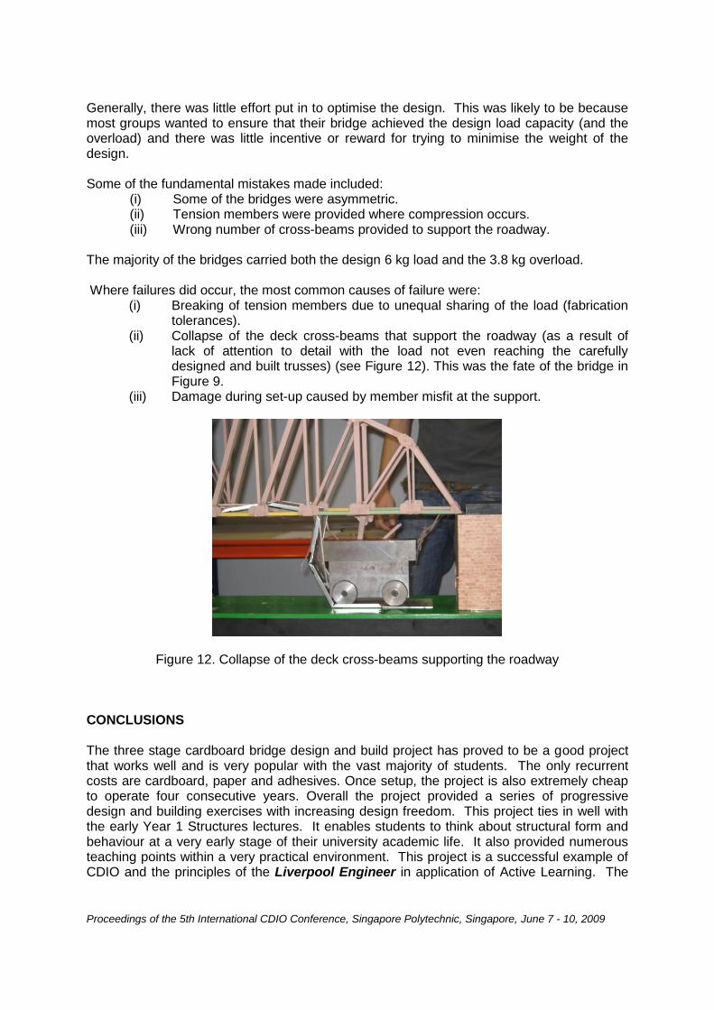
(ii) Collapse of the deck cross-beams that support the roadway (as a result of lack of attention to detail with the load not even reaching the carefully designed and built trusses) (see Figure 12). This was the fate of the bridge in Figure 9.
(iii) Damage during set-up caused by member misfit at the support.
Figure 12. Collapse of the deck cross-beams supporting the roadway
CONCLUSIONS The three stage cardboard bridge design and build project has proved to be a good project that works well and is very popular with the vast majority of students. The only recurrent costs are cardboard, paper and adhesives. Once setup, the project is also extremely cheap to operate four consecutive years. Overall the project provided a series of progressive design and building exercises with increasing design freedom. This project ties in well with the early Year 1 Structures lectures. It enables students to think about structural form and behaviour at a very early stage of their university academic life. It also provided numerous teaching points within a very practical environment. This project is a successful example of CDIO and the principles of the Liverpool Engineer in application of Active Learning. The

Proceedings of the 5th International CDIO Conference, Singapore Polytechnic, Singapore, June 7 - 10, 2009
whole project benefits from the environment provided by the new Active Learning Laboratory facility at the University of Liverpool. Students focused on the two-dimensional aspects of the bridge (as they had been taught in lectures), whereas many of the failures related to three-dimensional effects. It also highlighted in a very tangible way that many of the failures related to the details that they had not thought about rather than to their carefully considered designs. There were many examples of lessons that were learned as the project progressed. These included improved fabrication and assembly techniques, improved end-details and checking the bridge fitted onto the test set-up properly. In some cases lessons were not learned, such as the common unequal length of bars in tension members, consideration of lateral stability and the details of the deck cross-beam connection. In future the ambition and innovation of the details could benefit from an increase in the competitive aspect of the project. Maybe more emphasis and reward could be built into the project for achieving the lightest bridge that can carry the load. In addition to the structural lessons, the three projects are help students develop many other personal and professional skills such as communication and team working, time management and project costs. REFERENCES 1. Ressler S.J., “Designing and Building File-Folder Bridges – A Problem-Based Introduction to
Engineering”, http://bridgecontest.usma.edu, cited on 9 March 2009.
2. Dr Frame - Direct Manipulation Frame Analysis Environment, © Dr. Software LLC, 1998-2009,
http://www.drsoftware-home.com/ , cited on 14 March 2009.
3. West Point Bridge Design Contest, http://bridgecontest.usma.edu/ , cited on 14 March 2009.
Biographical Information Steve Millard is a Professor of Civil Engineering and Leader of the Construction and Infrastructure Research Group in the Department of Engineering at the University of Liverpool in the UK. He is interested in pedagogical developments such as computer aided learning (CAL), computer aided assessment (CAA), asynchronous and distance teaching and many aspects of active learning within Civil Engineering. Steve Jones is a Senior Lecturer in the Department of Engineering at the University of Liverpool in the UK. He has recently joined the Department to teach structural design. Previously he spent 28 years in industry as a Bridge Engineer with Civil Engineering consulting engineers. Corresponding author
Prof. Steve Millard Department of Engineering University of Liverpool

Proceedings of the 5th International CDIO Conference, Singapore Polytechnic, Singapore, June 7 - 10, 2009
Brodie Tower Brownlow Street Liverpool L69 3GQ UK +44-151-794-5224 [email protected]