development of co-firing method of pulverized coal and
TRANSCRIPT
Vo l . 5 3 N o . 1 2 0 2 0 1
Development of Co-Firing Method of Pulverized Coal and Ammonia
to Reduce Greenhouse Gas Emissions
NAGATANI Genichiro : Boiler Basic Design Department, Engineering Center, Boilers Business Unit, Resources, Energy & Environment Business Area ISHII Hiroki : Combustion Engineering Department, Engineering Center, Boilers Business Unit, Resources, Energy & Environment Business Area ITO Takamasa : Doctor of Engineering, Manager, Combustion & Engine Group, Technology Platform Center, Technology & Intelligence Integration OHNO Emi : Manager, Combustion Engineering Department, Engineering Center, Boilers Business Unit, Resources, Energy & Environment Business Area OKUMA Yoshitomo : Manager, Boiler Basic Design Department, Engineering Center, Boilers Business Unit, Resources, Energy & Environment Business Area
IHI is accelerating studies such as “building carbon-free energy networks using ammonia as fuel” in the mission of reducing greenhouse gas emissions. We have been researched and developed several items to construct the networks. This paper introduces the development of the co-firing method of pulverized coal and ammonia in a coal-fired plant. We have faced numerous challenges when using ammonia as a fuel. Among them, IHI uses its own large-capacity combustion test facility to evaluate the combustion performance, and through the feasibility study, identifies issues and examines countermeasures to realize ammonia co-firing. This paper presents technologies that have been developed for the global ammonia network that IHI is aiming for.
1. Introduction
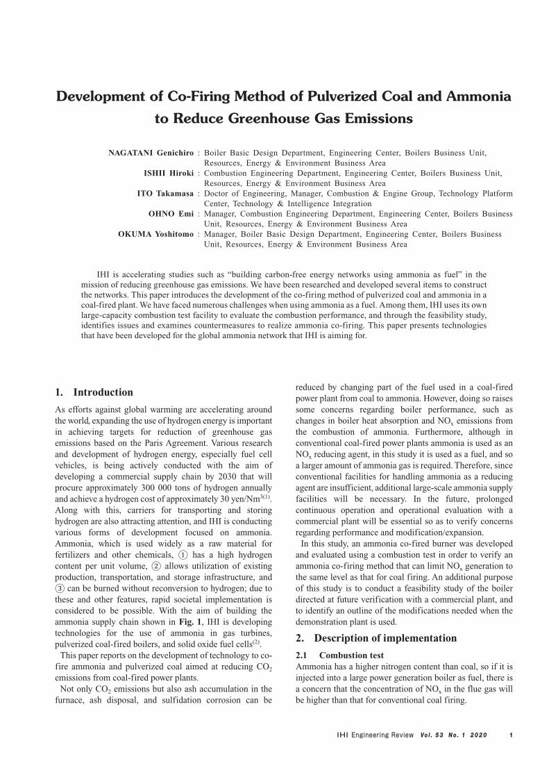
As efforts against global warming are accelerating around the world, expanding the use of hydrogen energy is important in achieving targets for reduction of greenhouse gas emissions based on the Paris Agreement. Various research and development of hydrogen energy, especially fuel cell vehicles, is being actively conducted with the aim of developing a commercial supply chain by 2030 that will procure approximately 300 000 tons of hydrogen annually and achieve a hydrogen cost of approximately 30 yen/Nm3(1). Along with this, carriers for transporting and storing hydrogen are also attracting attention, and IHI is conducting various forms of development focused on ammonia. Ammonia, which is used widely as a raw material for fertilizers and other chemicals, ① has a high hydrogen content per unit volume, ② allows utilization of existing production, transportation, and storage infrastructure, and ③ can be burned without reconversion to hydrogen; due to these and other features, rapid societal implementation is considered to be possible. With the aim of building the ammonia supply chain shown in Fig. 1, IHI is developing technologies for the use of ammonia in gas turbines, pulverized coal-fired boilers, and solid oxide fuel cells(2).
This paper reports on the development of technology to co-fire ammonia and pulverized coal aimed at reducing CO2 emissions from coal-fired power plants.
Not only CO2 emissions but also ash accumulation in the furnace, ash disposal, and sulfidation corrosion can be
reduced by changing part of the fuel used in a coal-fired power plant from coal to ammonia. However, doing so raises some concerns regarding boiler performance, such as changes in boiler heat absorption and NOx emissions from the combustion of ammonia. Furthermore, although in conventional coal-fired power plants ammonia is used as an NOx reducing agent, in this study it is used as a fuel, and so a larger amount of ammonia gas is required. Therefore, since conventional facilities for handling ammonia as a reducing agent are insufficient, additional large-scale ammonia supply facilities will be necessary. In the future, prolonged continuous operation and operational evaluation with a commercial plant will be essential so as to verify concerns regarding performance and modification/expansion.
In this study, an ammonia co-fired burner was developed and evaluated using a combustion test in order to verify an ammonia co-firing method that can limit NOx generation to the same level as that for coal firing. An additional purpose of this study is to conduct a feasibility study of the boiler directed at future verification with a commercial plant, and to identify an outline of the modifications needed when the demonstration plant is used.
2. Description of implementation
2.1 Combustion testAmmonia has a higher nitrogen content than coal, so if it is injected into a large power generation boiler as fuel, there is a concern that the concentration of NOx in the flue gas will be higher than that for conventional coal firing.
Vo l . 5 3 N o . 1 2 0 2 02
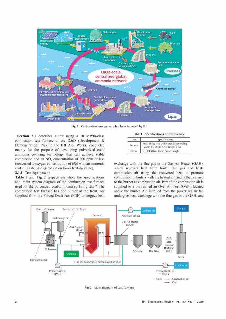
Section 2.1 describes a test using a 10 MWth-class combustion test furnace at the D&D (Development & Demonstration) Park in the IHI Aioi Works, conducted mainly for the purpose of developing pulverized coal/ammonia co-firing technology that can achieve stable combustion and an NOx concentration of 200 ppm or less (converted to oxygen concentration of 6%) with an ammonia co-firing rate of 20% (based on lower heating value).2.1.1 Test equipmentTable 1 and Fig. 2 respectively show the specifications and main system diagram of the combustion test furnace used for the pulverized coal/ammonia co-firing test(3). The combustion test furnace has one burner at the front. Air supplied from the Forced Draft Fan (FDF) undergoes heat
exchange with the flue gas in the Gas-Air-Heater (GAH), which recovers heat from boiler flue gas and heats combustion air using the recovered heat to promote combustion in boilers with the heated air, and is then carried to the burner as combustion air. Part of the combustion air is supplied to a port called an Over Air Port (OAP), located above the burner. Air supplied from the pulverizer air fan undergoes heat exchange with the flue gas in the GAH, and
Table 1 Specifications of test furnace
Item Specifications
FurnaceFront firing type with water jacket cooling(Width 3 × Depth 4.5 × Height 7 m)
Burner IHI-DF (Dual Flow) burner, single
Utilization of chemical raw materials and fertilizers
Ammonia tanker
Pipeline
Gas turbine powergeneration
Coal-fired boiler
Fuel cell
Renewableenergy
Waterelectrolyzer
Natural gas
Production ofammonia
Gasificationof coal
Biomass
Coal
Ammonia storagetank
Pipeline
Capture andstorage of CO2
Japan
Overseas
Urban area
Ammoniastorage tank
Large-scalecentralized globalammonia network
Fig. 1 Carbon-free energy supply chain targeted by IHI
Ambient air
Ammonia
Flue gas
Ambient air
Forced Draft Fan(FDF)
Primary Air Fan(PAF)
Pulverizer
Raw coal feeder
Raw coal bunker
InducedDraft Fan
(IDF)Cyclone
Gas-Air-Heater(GAH)
Bag filter
(Note) : Combustion air: Coal
Stack
Pulverizer air fan
Flue gas composition measurement position
Pulverized coal feeder
Furnace
Burner
Over Air Port(OAP)
Coal storage bin
Fig. 2 Main diagram of test furnace

Vo l . 5 3 N o . 1 2 0 2 0 3
is then supplied to the pulverizer, where it is used to dry coal and carry pulverized coal. The pulverized coal is stored in the coal storage bin. The stored coal is unloaded at a specified rate by the pulverized coal feeder and supplied to the burner by the Primary Air Fan (PAF), together with conveyance air. The pressure in the furnace is kept negative by using the Induced Draft Fan (IDF) to draw in the air supplied to the furnace. The flue gas is sampled at the position shown in the middle of Fig. 2 in order to analyze its composition using a gas analyzer (PG-250A, manufactured by HORIBA, Ltd.). In addition, a laser meter (LaserGas™ version II, manufactured by NEO Monitors AS) is installed at the stack inlet in order to continuously monitor the concentration of ammonia in the flue gas using infrared single-line absorption spectroscopy. This is to check that a large amount of ammonia is not released into the atmosphere when ammonia injected as fuel remains unburned.
Figure 3 shows a schematic diagram of the burner(3). The burner has an axially symmetric structure, with pulverized coal channels, air resistors, and wind boxes arranged symmetrically from the center in that order. Together with conveyance air, pulverized coal is supplied to the furnace through the pulverized coal channels. Combustion air is supplied from the wind boxes to the furnace. The air resistors arranged at the combustion air channels have multiple movable vanes located symmetrically with respect to the axis, and the swirl force of combustion air can be adjusted by adjusting vane angle. Combustion air is swirled to form a circulation flow of gas in the furnace. This circulation flow rapidly mixes the hot combustion gas and fuel, promoting discharge of volatile matter and N content in the fuel, and thereby forming a stable flame and reducing NOx in the reducing atmosphere.
Ammonia is carried to the burner by the ammonia supply facility. The ammonia supply facility can be equipped with four 0.5-ton cylinders and has two hot water vaporizers. Ammonia is gasified by the vaporizers and carried to the burner, with the mass flow rate being controlled. Ammonia can be supplied at a flow rate of up to 0.38 t/h. In this study, ammonia is supplied from the center of the pulverized coal burner. This is to reduce the modifications required when applying the ammonia co-firing technology to a commercial plant.
2.1.2 Test conditionsThe following four evaluations were conducted:
(1) Checking for unburned ammonia and confirming flame stability during ammonia co-firing
(2) Effect of two-stage combustion ratio, which is the ratio of air quantity injected from OAP to all the combustion air, on flue gas composition
(3) Effect of heat input on flue gas composition(4) Effect of fuel ratio of coal, which is the ratio of fixed
carbon to volatile matter, on flue gas compositionTable 2 shows the test conditions for each item. In this test,
the ammonia co-firing rate was constantly 20%, based on lower heating value. The fuel ratio of the coal used in the test (mass ratio of fixed carbon and volatile matter (–)) was 1.16 to 1.70 (bituminous coal).2.1.3 Test results2.1.3.1 Checking for unburned ammonia and
confirming flame stability during ammonia co-firing
Figure 4 shows the change over time in the measured values of flue gas composition during coal firing and ammonia co-firing with an ammonia co-firing rate of 20%(4). The amount of coal burned during ammonia co-firing is lower than that during coal firing by 20%, which indicates that the CO2 concentration in the flue gas is also lower by approximately 20%. In addition, since the ammonia concentration at the stack inlet is 1 ppm, it can be concluded that almost all of the ammonia injected into the furnace is consumed within it.
Figure 5 shows the appearance of the flame(4). When the swirl force of the combustion air is at the same extent, the flame ignition position during ammonia co-firing is farther from the burner port than that during coal firing. This is probably because ammonia, which is flame retardant, is supplied from the center of the burner. However, by adjusting the swirl force of the combustion air, the flame ignition position during ammonia co-firing can be adjusted to that during coal firing. The test results reported in this paper were obtained with the flame ignition position during ammonia co-firing adjusted to that during coal firing.
As described above, during ammonia co-firing, the flue gas composition is stable over time, there is no unburned ammonia, and the flame shape is almost the same as that during coal firing; it was therefore concluded that ammonia co-firing is rendered feasible by using a burner that is structured to supply ammonia from the center of the pulverized coal burner.2.1.3.2 Effect of two-stage combustion ratio on flue
gas compositionThe two-stage combustion ratio is an important parameter for controlling NOx in the flue gas, and is defined as the mass ratio of the amount of air for two-stage combustion to
Table 2 Conditions of co-firing experiment
Item Unit Base conditions Low-load conditions
Heat input MW 10 6.0 – 8.6
Air ratio — 1.2 1.1 – 1.7
Two-stage combustion ratio — 0.3 0.2 – 0.4
Combustion air
NOx reduction region
Pulverized coal + Primary air
Ammonia
Fig. 3 Enlarged view of burner used in co-firing experiment

Vo l . 5 3 N o . 1 2 0 2 0 4
the total amount of air injected into the furnace. In order to evaluate how the two-stage combustion ratio affects flue gas composition, an ammonia co-firing test was conducted using the two-stage combustion ratio as a parameter, with a heat input of 10 MW and an air ratio of 1.1 to 1.2. The following reports the test results.
Figure 6 shows the relationship between the two-stage combustion ratio and NOx in flue gas, and Fig. 7 shows the relationship between the two-stage combustion ratio and unburned carbon in ash(4).
For coal firing, NOx decreases monotonically as the two-stage combustion ratio increases from 20% to 40%. In contrast, for ammonia co-firing, NOx is lowest when the two-stage combustion ratio is approximately 30%. It has
been reported that, also in the case of coal firing, although NOx decreases as the two-stage combustion ratio increases, NOx increases when the two-stage combustion ratio exceeds a certain value(5). This is because, when the two-stage combustion ratio increases, NOx production is suppressed at the burner level where the air ratio is low, but the unburned carbon remains and is burned at the two-stage combustion position, which causes the nitrogen content in the fuel to oxidize, thereby producing NOx. Within the range of two-stage combustion ratio used in this test, this trend can only be seen for ammonia co-firing. Volatile matter of coal and NH3 are presumed to be what burns at the burner level, but for ammonia co-firing, the amount of these components is larger than that for coal firing. Consequently, it is presumed
Direction of gas flow
(b) Ammonia co-firing
Before adjustment of combustion air swirl force After adjustment of combustion air swirl force
(a) Coal firing
Port
Port Port
Fig. 5 Flame appearance
20
18
16
14
12
10
4
8
6
2
013:00 13:05 13:10 13:15
Time (h:min)
CO
2 in
flu
e ga
s (c
onve
rted
to O
2 co
ncen
trat
ion
of 6
%),
O
2 in
flu
e ga
s (d
ry%
), N
H3
at s
tack
inle
t (p
pm)
: CO2
: O2
: NH3 at stack inlet
20
015:30 15:35 15:40 15:45
Time (h:min)
CO
2 in
flu
e ga
s (c
onve
rted
to O
2 co
ncen
trat
ion
of 6
%),
O
2 in
flu
e ga
s (d
ry%
), N
H3
at s
tack
inle
t (p
pm)
: CO2
: O2
: NH3 at stack inlet
18
16
14
12
10
4
8
6
2
(a) During coal firing (b) 20% ammonia co-firing
Fig. 4 Time history of flue gas composition

Vo l . 5 3 N o . 1 2 0 2 0 5
that, for ammonia co-firing and with a high two-stage combustion ratio, the ratio of air to the amount of volatile matter of coal and NH3 at the burner level is low, and a relatively large amount of unburned carbon remains, which is burned at the two-stage combustion position, thereby causing NOx to increase.
In the range of two-stage combustion ratio used in this test, the amount of unburned carbon in ash is almost the same for ammonia co-firing and coal firing, which suggests that with an appropriate two-stage combustion ratio, it is possible to carry out ammonia co-firing such that NOx does not exceed that which occurs with coal firing.2.1.3.3 Effect of heat input on flue gas compositionIn order to apply the ammonia co-firing technology to a commercial plant, it is desirable that ammonia co-firing be
possible even at loads other than the rated load. However, there is a concern that in the low-load range, as the fuel supply decreases, the temperature in the furnace will decrease and the combustion of ammonia cannot be maintained, causing part of the ammonia to remain unburned. With regard to this, in order to confirm whether the flue gas composition is the same for ammonia co-firing and coal firing even in the low-load range, pulverized coal and ammonia were co-fired at a low load with a constant ammonia co-firing rate of 20%, and the flue gas composition was evaluated. Figures 8 and 9 respectively show the relationship between heat input and NOx and that between heat input and unburned carbon in ash(6).
From Fig. 8, it can be seen that for both coal firing and 20% ammonia co-firing, NOx increases as heat input decreases, and the increase rate of NOx for ammonia co-firing is almost the same as that for coal firing. This suggests
0
12
8
10
2
20
16
14
403020100 50
Unb
urne
d ca
rbon
in a
sh (
%)
Two-stage combustion ratio (%)
6
4
18
(Note) Air ratio : 1.1 to 1.2
: Coal firing: Ammonia co-firing
Fig. 7 Relationship between two-stage combustion ratio and unburned carbon
0
200
150
100
50
300
250
403020100 50
NO
x (c
onve
rted
to O
2 co
ncen
trat
ion
of 6
%)
(pp
m)
Two-stage combustion ratio (%)
: Coal firing: Ammonia co-firing
Fig. 6 Relationship between two-stage combustion ratio and NOx
0
200
150
100
50
350
300
250
98765 10NO
x co
ncen
trat
ion
(con
vert
ed to
O2
conc
entr
atio
n of
6%
) (
ppm
)
Heat input (MW)
: Coal firing: Ammonia co-firing
Fig. 8 Relationship between heat input and NOx concentration
0
12
8
10
2
20
16
14
Unb
urne
d ca
rbon
in a
sh (
%)
Heat input (MW)
6
4
18
98765 10
: Coal firing: Ammonia co-firing
Fig. 9 Relationship between heat input and unburned carbon

Vo l . 5 3 N o . 1 2 0 2 0 6
that even in the low-load range, NOx concentration during ammonia co-firing is almost the same as that during coal firing. From Fig. 9, however, it can be seen that with a heat input of 7.3 MW, the amount of unburned carbon in ash during ammonia co-firing is approximately twice that during coal firing. This is presumably because, under conditions where heat input is low, the ammonia flow rate and linear momentum of ammonia decrease, so that reaction of the oxygen in combustion air with ammonia is promoted while its reaction with pulverized coal is inhibited. To identify the cause of this phenomenon, it is necessary to collect more data and verify reproducibility.2.1.3.4 Effect of fuel ratio of coal on flue gas
compositionIn a commercial plant, subbituminous coal may be used as fuel in addition to bituminous coal. Assuming use of subbituminous coal, the effect of the fuel ratio of the coal on flue gas composition during ammonia co-firing was evaluated in order to assess whether flue gas composition is the same for ammonia co-firing and coal firing even when ammonia is co-fired with low-fuel-ratio coal. The types of coal used have fuel ratios of 1.16 and 1.70, as shown in Table 3. Figure 10 shows the results of NOx measurement(6). In this test, heat input was set to 7 MW for equipment-related reasons.
From Fig. 10, it can be seen that, for both coal firing and ammonia co-firing, NOx increases slightly as the fuel ratio increases. In addition, for both fuel ratios, NOx concentration during ammonia co-firing is lower than that during coal firing. This suggests that the fuel ratio of the coal does not greatly affect NOx concentration in the flue gas during ammonia co-firing. This is because for 20% ammonia co-firing, 90% or more of the nitrogen contained in the injected fuel (coal and ammonia) comes from ammonia, so that the absolute amount of injected nitrogen does not change significantly within a fuel ratio range of 1.16 to 1.70; the fuel ratio of the coal is therefore considered to have little effect on the NOx concentration in the flue gas.
This result suggests that ammonia co-firing can be used even with low-fuel-ratio coal, such as subbituminous coal.2.2 Feasibility study with a large coal-fired power
generation boiler2.2.1 PurposeSection 2.2 describes a feasibility study of ammonia co-firing in an existing large coal-fired power generation boiler, and gives an evaluation of the resulting boiler performance. Coal firing facilities were evaluated by considering various performance data related to performing ammonia co-firing, and this evaluation was used to examine issues arising from the application of ammonia co-firing — such as whether it is possible to use the facilities as they are, or whether additions/modifications are necessary — together with possible solutions.2.2.2 Main conditions of boiler feasibility studyIn this development, the feasibility study was conducted with an existing 1 000 MW-class large coal-fired power generation boiler. Table 4 shows details of the conditions
under which the study was conducted(3). Ammonia was mixed with coal — the main fuel — at an ammonia co-firing rate of 20% with respect to boiler heat input. In general, boiler performance deteriorates over time when operated for a prolonged time period, but this study assumes the performance of a newly installed boiler. With regard to load, the Maximum Continuous Rating (MCR) was used, at which the quantities of combustion air and flue gas are largest. With regard to the ammonia injection method, it was assumed that ammonia was supplied to all burners at an ammonia co-firing rate of 20% so as to achieve 20% ammonia co-firing in the entire plant.
0
300
200
250
50
Fuel ratio of coal (–)
150
100
1.81.61.41.21.0 2.0
350
NO
x co
ncen
trat
ion
(con
vert
ed to
O2
conc
entr
atio
n of
6%
) (
ppm
)
: Coal firing: Ammonia co-firing
Fig. 10 Relationship between fuel ratio and NOx concentration
Table 4 Main conditions of feasibility study for 1 000 MW-class boiler
Item Description
Plant 1 000 MW-class power plant
Ammonia co-firing rate 20% based on higher heating value
Reference boiler performance Assumes a new boiler.
Coal type Assumes use of design coal with new boiler.
Load Evaluated at MCR.
Co-firing rate at each burner 20% at each burner
Table 3 Fuel properties
Item Unit Coal A Coal B NH3
Lower heating value MJ/kg 29.0 29.1 18.5
Proximate analysis
Moisture content wt% 2.2 2.0
—
Fixed carbon wt% 56.2 48.1
Volatile matter wt% 33.0 41.6
Ash content wt% 10.8 10.3
Fuel ratio — 1.70 1.16
Ultimate analysis
Carbon wt% 71.1 69.7
—
Hydrogen wt% 4.6 5.3
Nitrogen wt% 1.4 1.1
Oxygen wt% 11.7 13.2
Total sulfur wt% 0.4 0.5
(Note) Moisture content: Air-dry basis; Other items: Dry basis

Vo l . 5 3 N o . 1 2 0 2 0 7
2.2.3 Details of items examined in boiler feasibility study
Section 2.2.3 evaluates the three following items:(1) Evaluation of boiler efficiency and material balance
Using the properties of the coal-ammonia mixture fuel, combustion calculations are carried out to examine fuel consumption and air-gas balance.
(2) Examination of modifications to boiler systemThe capacity of the boiler equipment, including
auxiliary equipment, is examined using the air and gas quantities produced by the combustion calculations.
(3) Examination of ammonia supply systemThe ammonia injection position, equipment installed
in the system, and ammonia gas purging method are examined.
2.2.3.1 Evaluation of boiler efficiency and material balance
Here, a comparison is given of boiler performance for coal firing and ammonia co-firing, and the material balance for each piece of equipment is verified; this data allows examination of whether modifications to existing facilities are necessary. Table 5 shows the heating values of the coal (design coal) and ammonia used in this study(3).
As shown in Table 4, the MCR is used in this study. Figure 11 shows the boiler efficiencies during coal firing and ammonia co-firing(3). It can be seen that the boiler efficiency during ammonia co-firing is slightly lower than that during coal firing. This is presumably because, although ammonia co-firing reduces the loss due to unburned coal, burning ammonia increases the moisture content in the boiler flue gas, which increases the latent heat of the moisture discharged from the gas.
Figure 12 shows the coal consumptions during coal firing and ammonia co-firing(3). Ammonia co-firing with coal at a co-firing rate of 20% results in a simple decrease in the amount of injected coal. However, because ammonia has a low heating value per unit mass, the total fuel consumption
(coal + ammonia) for ammonia co-firing is higher than for coal firing, and so the running cost for ammonia co-firing tends to increase.
Figure 13 shows the combustion air quantities during coal firing and ammonia co-firing(3). Figure 14 shows the corresponding flue gas quantities(3). With regard to combustion air, although the total combustion air quantity is small, the air flow ratio changes, which tends to increase the secondary combustion air ratio. With regard to the flue gas, the quantity during ammonia co-firing is slightly higher than that during coal firing. Judging from these results, detailed studies — for both the air and gas sides — are required
0
80
60
40
20
100
Coal firing Ammonia co-firing
(Note) *1 : At MCR (maximum continuous rating)
Boi
ler
effi
cien
cy*1
(%
)
Fig. 11 1 000 MW-class boiler_boiler efficiency
0
40
30
20
10
50
Coal firing Ammonia co-firing
(Note) *1 : At MCR (maximum continuous rating)
Com
bust
ion
air*1
(m
3 /m
in)
× 103
Fig. 13 1 000 MW-class boiler_combustion air
0
400
300
200
100
500
Coal firing Ammonia co-firing
(Note) *1 : At MCR (maximum continuous rating)
Coa
l con
sum
ptio
n*1 (
t/h)
Fig. 12 1 000 MW-class boiler_fuel consumption
0
40
30
20
10
50
Coal firing Ammonia co-firing
(Note) *1 : At MCR (maximum continuous rating)
Flu
e ga
s qu
anti
ty*1
(m
3 /m
in)
× 103
Fig. 14 1 000 MW-class boiler exhaust gas volume
Table 5 Calorific value of fuel used in feasibility study for 1 000 MW-class boiler
Item Unit Coal (design coal) Ammonia
Higher heating value MJ/kg 24.1 22.4

Vo l . 5 3 N o . 1 2 0 2 0 8
regarding surplus capacity of the draft system and other factors in order to determine if draft system components designed for coal firing can be used for ammonia co-firing without modifications.
2.2.3.2 Examination of modifications to boiler systemAfter first confirming a common system configuration, Section 2.2.3.2 examines modifications to the boiler system. Figure 15 shows a common system configuration for a coal-
Flue gas
Stack
⑥ Environmental facilities
③-3
③-2
③-1
Induced Draft Fan(IDF)
Forced Draft Fan(FDF)
Primary Air Fan(PAF)
① Heating surfaces of the boiler
Coal bunker
④ Pulverizer
⑤ Gas-Air-Heater(GAH)
Ambient air
Ambient air
② Burner
It was confirmed that during ammonia co-firing, NOx concentration is almost the same as during coal firing, and that CO2, SO2, and dust decrease as the amount of injected coal decreases. Although the environmental regulation values are satisfied, it was confirmed that there is an increase in the amount of gas and moisture content of the flue gas, so it is necessary to further evaluate modification and expansion of environmental facilities.
No. Item Description
Heating surfaces of the boiler
Burner
PAF
FDF
IDF
Pulverizer
GAH
Environmental facilities(NOx removal equipment, dust collector, and SOx removal equipment)
①
②
③-1
③-2
③-3
④
⑤
⑥
As a result of numerical analysis that simulates a boiler(3), it was found that the heat recovery quantity is almost the same for coal firing and ammonia co-firing, and since the steam and gas temperatures throughout the system are not different from those that were designed, ammonia co-firing requires no modifications to the boiler heating surfaces.
Basically, burners designed for coal firing are also used for ammonia co-firing. However, it is necessary to add ammonia supply facilities, including equipment that injects ammonia gas into the burner and systems that address concerns arising from the use of ammonia.
As stated in the preceding description, the PAF is used to carry pulverized coal to the burner. During ammonia co-firing, some of the pulverized coal used as fuel is replaced by ammonia gas, and so the amount of air used to carry coal decreases; therefore, the PAF requires no modifications.
The air required for combustion is supplied by the PAF and FDF. During ammonia co-firing, the amount of air supplied by the PAF decreases, and the FDF has to compensate for this in order to ensure the required amount of air for combustion. Hence, the flow rate on the FDF side tends to increase. In the model plant used in this study, there is some surplus capacity in the design specification of the FDF, and so no modification is necessary. However, depending on the design specification, such surplus capacity may not exist, and so careful consideration is required in order to determine whether modification is needed.
As a result of material balance evaluation, it was found that the gas quantity tends to increase slightly for ammonia co-firing. As with the FDF, in the model plant used in this study, there is some surplus capacity in the design specification of the IDF, and so no modification is necessary. However, careful consideration is required, since modification may be needed depending on the setting in which surplus capacity is ensured.
Because the amount of injected coal decreases for ammonia co-firing, the operation load of the pulverizer decreases. Therefore, no modification of the pulverizer is necessary. In addition, because the amount of injected coal decreases, the required temperature of the air for drying the coal decreases. As a result, some of the heat recovered by the GAH during coal firing remains in the flue gas during ammonia co-firing, and so the flue gas temperature during ammonia co-firing tends to be higher.
The flue gas temperature tends to increase because not all the heat from the gas side can be recovered due to a decrease in pulverizer inlet temperature, increase in gas flow rate, change in gas properties, etc. Flue gas temperature needs to be examined in detail, but since it increases by around 10 degrees Celsius, this level of increase can be absorbed by the surplus capacity available when the facility is newly installed, and so no modification of the GAH is required.
(a) System configuration of coal-fired boiler system
(b) Items examined in coal-fired boiler system
Fig. 15 General system configuration of coal-fired boiler system

Vo l . 5 3 N o . 1 2 0 2 0 9
fired boiler, together with points for examination(3).In a coal-fired boiler, combustion air is sent to the GAH by
the FDF. In the GAH, the element is heated when it comes into contact with the hot gas at the boiler outlet (recovery of heat from the boiler flue gas), the heated element heats combustion air, and the heated combustion air promotes combustion in the boiler. The hot air from the GAH is sent to the burner. At the same time, part of the air sent by the FDF is supplied from the top of the boiler in order to supply combustion air in two steps, thereby reducing NOx in the combustion flue gas. This reduces the amount of excess air supplied to the burner and intentionally forms a reducing atmosphere around it, thereby reducing NOx (Fuel NOx) caused by the N content in the fuel. Overall, supplying air in two steps compensates for the shortage of oxygen, thereby achieving the required air excess ratio.
The rest of the combustion air supplied from the FDF is sent to the pulverizer by the PAF. The primary air is used to carry the pulverized coal pulverized by the pulverizer to the burner and also to dry the coal. Part of the primary air is sent to the GAH and heated. This hot air is mixed with cool air at the pulverizer inlet to adjust the temperature to one suitable for drying the coal in the pulverizer, and then sent to the pulverizer.
After combustion by the burner, the generated combustion flue gas is drawn by the IDF. For this reason, the furnace is always maintained at negative pressure. Heat is recovered from the combustion flue gas by the heating surfaces of the boiler and by the GAH, and then its gas properties are adjusted by passing it through environmental facilities that remove NOx, dust, and SOx. Finally, the gas is released into
the atmosphere.Here, the six following parts were examined with regard to
modification of the boiler system (see Fig. 15 for details of these parts):① Heating surfaces of the boiler② Burner③ Draft system components (PAF, FDF, and IDF)④ Pulverizer⑤ GAH⑥ Environmental facilities (NOx removal equipment,
dust collector, and SOx removal equipment)2.2.3.3 Examination of ammonia supply systemIn order to achieve ammonia co-firing, it is necessary to add an ammonia gas system between the ammonia gasification facility and the burner. Figure 16 is a schematic diagram of the ammonia gas system examined in this study(3). During ammonia co-firing, liquid ammonia is gasified and the ammonia gas is co-fired with coal, and so, in order to ensure reliability, the ammonia gas system has basically the same system configuration as a fuel system designed for a boiler which uses a gas fuel as its main fuel. In addition, the ammonia gas and coal are co-fired coaxially, and all burners are provided with ammonia gas piping so that each burner can co-fire at a co-firing rate of 20%. One of the most important issues when considering ammonia co-firing is not allowing ammonia gas, which is deleterious and poisonous, to leak out of the system, i.e., not allowing it to be released into the atmosphere. Because this requirement constitutes a major premise, a basic design policy is that ammonia gas be purged to pretreatment facilities by using N2, etc., rather than released into the atmosphere as is usually done with other
Relief valve
Relief valve
To ammoniagasificationfacility
N2 gas
To ammonia gasificationfacility
From ammonia gasificationfacility
N2 gas
Shutoff valve
Fuel flowcontrol valve
Flow meter
Pressure control valve
Burner
(Note) : Ammonia gas : N2 gas
N2 gas
Fig. 16 Schematic diagram of 1 000 MW-class boiler_ ammonia gas system

Vo l . 5 3 N o . 1 2 0 2 0 10
gas fuels.In the current study, only a basic system configuration was
examined, but in the future it will be necessary to verify boiler operation items and specifications for ammonia co-firing, and perform further examination of the details of the system taking these factors into account. In addition, consideration of safety is indispensable when using ammonia gas, and so we also intend to examine safety measures.
3. Conclusion
As a method of reducing CO2 emissions from coal-fired power plants, we developed a pulverized coal/ammonia co-firing technology in order to use ammonia — a hydrogen carrier — as fuel for coal-fired power generation.
In the combustion test, it was demonstrated that, even for ammonia co-firing, NOx can be limited to the same level as for coal firing and a stable flame maintained by supplying ammonia from the center of a coal-fired burner. In addition, the effect of the two-stage combustion ratio, heat input, and coal fuel ratio on flue gas composition was evaluated, and it was confirmed that, under appropriate conditions, NOx concentration does not exceed that for coal firing. From the results of this test, it was found that there is almost no necessity to install additional large NOx-related facilities when performing co-firing of pulverized coal and ammonia. Going forward, in order to enhance feasibility for societal implementation, we will evaluate the possibility of ammonia co-firing with a lower heat input and develop a burner that can co-fire pulverized coal and ammonia at co-firing rates above 20%.
In the feasibility study for large coal-fired power generation boilers, it was found that the only modifications required for ammonia co-firing were in the ammonia supply system, with all other facilities being usable in their existing specifications. However, this result was obtained through evaluation under only one set of specific conditions, and continuing consideration is required due to dependency of the result on coal type, ammonia co-firing rate, etc. In addition, we will continue investigation of subjects related to boiler operation, such as timing of fuel injection, operation at low loads, and methods for stopping ammonia co-firing, for purging ammonia, and for detoxifying ammonia.
We will continue research and development regarding the performance and facility-related problems to be solved arising from the ammonia co-firing performed in this study, but in the future, it will be necessary to perform operational
evaluation using a commercial plant so that this technology can be applied to existing plants. In addition to developing new burners and conducting feasibility studies in order to solve relevant problems, we will perform early determination of candidate demonstration sites for the evaluation of operation on a larger scale, and conduct a demonstration project. As the world moves toward greater consideration of the environment, IHI will accelerate its research and development of ammonia co-firing technology so that it can contribute to reducing greenhouse gas emissions.
— Acknowledgments —
This study was conducted as “Ammonia Direct Combustion,” research commissioned as part of the Council for Science, Technology and Innovation’s Cross-ministerial Strategic Innovation Promotion Program (SIP) “Energy Carriers” (administered by the Japan Science and Technology Agency (JST)). We would like to express our gratitude to all relevant parties.
REFERENCES
(1) Ministerial Council on Renewable Energy, Hydrogen and Related Issues : Basic Hydrogen Strategy, < https://www.meti.go.jp/english/press/2017/pdf/1226_003b.pdf >, accessed 2019-09-03
(2) IHI Corporation : Stop the Global Warming by Hydrogen Energy Utilization Technology, IHI Engineering Review, Vol. 51, No. 1, 2018, pp. 2-3
(3) Japan Science and Technology Agency : SIP (Cross-ministerial Strategic Innovation Promotion Program) Final Report, < https://www.jst.go.jp/sip/dl/k04/end/team6-14.pdf >, accessed 2019-09-03
(4) H. Ishii, E. Ohno, T. Kozaki, T. Ito and T. Fujimori : Co-firing method of pulverized coal and ammonia for suppressing the NOx generation, The 23rd National Symposium on Power and Energy Systems, JSME, 2018, C231
(5) H. Makino, M. Kimoto, M. Sato and T. Ninomiya : NOX reduction by multi stage air injection on pulverized coal combustion, Journal of the Fuel Society of Japan, Vol. 69, No. 9, 1990, pp. 856-862
(6) H. Ishii, E. Ohno, T. Kozaki, T. Ito and T. Fujimori : Co-firing method of pulverized coal and ammonia for suppressing the NOx generation: Part 2, The 24th National Symposium on Power and Energy Systems, JSME, 2019, D123