development of compositionally modulated multilayer zn–ni
TRANSCRIPT

201 (2007) 7896–7904www.elsevier.com/locate/surfcoat
Surface & Coatings Technology
Development of compositionally modulated multilayer Zn–Ni deposits asreplacement for cadmium
Prabhu Ganesan, Swaminatha P. Kumaraguru, Branko N. Popov ⁎
Department of Chemical Engineering, University of South Carolina, Columbia, South Carolina 29208, USA
Received 17 December 2006; accepted in revised form 16 March 2007Available online 30 March 2007
Abstract
Compositionally modulated multilayer (CMM) Zn–Ni deposits were electrodeposited from single acidic bath (pH=4.7) by using apotentiostatic sequence. The Zn and Ni composition in the alloy was tailored as a function of distance from the steel substrate. X-ray diffractionstudies of the deposit showed the presence of γ-phase with a composition of Ni5Zn21. The corrosion properties of modulated multilayer coatingswere studied in 5% NaCl solution using electrochemical corrosion techniques. The polarization resistance of the deposits varied as a function of Nicontent between 1700 and 3440Ω. CMM Zn–Ni with 20 wt% Ni exposed in ASTM B117 salt spray test did not show any red rust formation after400 h.© 2007 Elsevier B.V. All rights reserved.
Keywords: Compositionally modulated multilayer; Zn–Ni alloy; Cadmium replacement; Corrosion rate; Microhardness
1. Introduction
Cadmium has been used for years as a corrosion resistantcoating in aerospace, electrical, and fastener industries owing toits excellent corrosion resistance and engineering properties [1].Currently, efforts are being made to find a suitable alternativebecause of toxicity of the metal and its salts, risk of failure dueto hydrogen embrittlement and to avoid cyanide baths forplating cadmium [2–5]. Hydrogen embrittlement in steel occursdue to the absorbed atomic hydrogen which is discharged as anunavoidable electrode reaction during electrodeposition. Zinc–nickel alloy coatings are being extensively studied as areplacement for cadmium coating due to their good corrosionprotection property [6–8], superior formability, and improvedwelding characteristics [9–11]. Zn–Ni alloys containing 15–20 wt% nickel have been shown to possess four times morecorrosion resistance than cadmium–titanium deposit [12].However, Zn–Ni alloys have more negative potential thancadmium due to the high zinc content in the deposit and hencedissolve rapidly in corrosive environments. Although Ni is
⁎ Corresponding author. Tel.: +1 803 777 7314; fax: +1 803 777 8265.E-mail address: [email protected] (B.N. Popov).
0257-8972/$ - see front matter © 2007 Elsevier B.V. All rights reserved.doi:10.1016/j.surfcoat.2007.03.033
nobler than Zn, the co-deposition of Zn–Ni is anomalous and ahigher percent of Zn is present in the final deposit [13,14].
Typical nickel composition in the alloy is approximately 5–10%, and further increase in nickel content has been achievedby using a higher Ni amount in the plating bath [15–17]. Anenhancement in the nickel composition would lead to morepositive open-circuit potential, which in turn will reduce thedriving force for the galvanic corrosion. The barrier propertiesassociated with nickel-rich deposits are also superior comparedto other coatings [18–20]. Zn–Ni alloys prepared by the pulseprocess [21] and a multilayer approach [22] were also adoptedin order to obtain high corrosion resistant alloys. Severalattempts have been made to decrease the anomaly and increasethe nickel content either by introducing inert species in the bathor by developing a ternary alloy [23–27]. Co-deposition ofphosphorous along with Zn–Ni improves the corrosion [25] andhydrogen permeation [26] characteristics of the electrodeposits.Zhou and Keefe [32] studied the effect of tin addition on theanomalous deposition of Zn–Ni alloy. The nickel ratioincreased from 6 to 8% with the addition of small amounts oftin. However, the observed small increase of Ni content in thealloy did not improve the Zn–Ni barrier properties. Other alloysstudied as corrosion protection coatings include Zn–Mn [28–30] and Zn–Sn [31,32].

Fig. 2. Effect of applied potential on the composition of Zn–Ni deposits.
7897P. Ganesan et al. / Surface & Coatings Technology 201 (2007) 7896–7904
The objective of the present investigation is to synthesizecompositionally modulated Zn–Ni multilayer deposits withvarying nickel concentration (from 15 to 30 wt.%) on carbonsteel substrate. The goal is to deposit a zinc rich deposit close tothe steel substrate and nickel rich deposit on the surface. Also,the goal of the present study is to evaluate the physicalproperties of the prepared coatings such as adhesion andmicrohardness and compare their corrosion properties in 5%NaCl solution with commercial Zn–Ni (13–15% Ni) andcadmium coatings.
2. Experimental
2.1. Electrolyte preparation and deposition
The deposition was performed using chloride electrolyte(pH=4.7) consisting of nickel chloride (NiCl2.6H2O), zincchloride (ZnCl2.7H2O), ammonium chloride and boric acid.Plating and subsequent corrosion studies were done on low-carbon cold-rolled steel plates (Q-Panels, USA) of 0.8 mm thickand 4×2.5 cm2 in area. Initially, the steel samples weremechanically polished with successively finer grades of emerypaper. Next, they were degreased with soap water and rinsedwith de-ionized water followed by treatment in 10% (v/v)sulphuric acid solution for 1 min to remove any adherent oxidelayer present on the surface. Finally, the samples were washedin de-ionized water. This procedure was repeated until a cleanand smooth surface was obtained. The plating was carried outinitially at different potentials followed by a potential sequenceshown in Fig. 1.
2.2. Material characterization and mechanical propertiesevaluation
Energy Dispersive Analysis using X-rays (EDAX) was usedto analyze the distribution of the elements in the final deposit.To ensure accuracy of the element distributions, EDAX wasdone at several points on the surface of the substrate. The
Fig. 1. Schematic of the potential sequence used for the CMM Zn–Ni deposits.
surface morphology and the microstructure of the coating wereanalyzed using Scanning Electron Microscopy by means of aHitachi S-2500 Delta Scanning Electron microscope. Backscat-tering scanning electron microscope (BSEM) and electronmicroprobe analysis (EMPA, Cameca SX50) were used todetermine the distribution of the elements across the thicknessof the deposits.
The mechanical characterization studies such as adhesionand micro-hardness were performed according to ASTM B 571-97 and ASTM B 578-87 respectively. A Vickers hardnessindenter (Buehler Micromet 1 Microhardness Tester) was usedto indent the prepared Zn–Ni alloys with a diamond tip.Commercial Zn and Zn–Ni deposits were also subjected tohardness measurements for comparison. The physical defor-mation that occurs during the indentation process at an appliedload of 100 g for 10–15 s was observed under a microscope andthe dimensions of the depression were marked. Vickershardness number (VHN) was calculated based on the observa-tions made on the indent using the formula
VHN ¼ 2Pd2
sina2
� �ð1Þ
where, d is the diagonal length left by the diamond shapedpyramid indenter. The angle between the phases of the pyramidis α=136°. P is the load used in kilograms and the units of d arein millimeter.
2.3. Electrochemical characterization and ASTM B 117 SaltSpray Test
A variety of electrochemical techniques such as linear andTafel polarization studies were used to evaluate the barrierresistance properties of the coating. The electrochemicalcharacterization was performed using an EG&G PAR model273 A potentiostat/galvanostat interfaced with a computer and athree-electrode setup in 5% NaCl solution. The steel substratewith the coating was used as the working electrode and aplatinum mesh was used as the counter electrode. A saturatedcalomel electrode (SCE) was used as the reference electrode.All potentials mentioned in this study are referenced to the SCE.
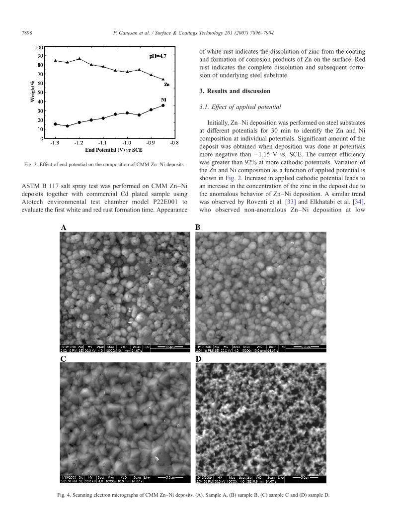
Fig. 3. Effect of end potential on the composition of CMM Zn–Ni deposits.
7898 P. Ganesan et al. / Surface & Coatings Technology 201 (2007) 7896–7904
ASTM B 117 salt spray test was performed on CMM Zn–Nideposits together with commercial Cd plated sample usingAtotech environmental test chamber model P22E001 toevaluate the first white and red rust formation time. Appearance
Fig. 4. Scanning electron micrographs of CMM Zn–Ni deposits. (A
of white rust indicates the dissolution of zinc from the coatingand formation of corrosion products of Zn on the surface. Redrust indicates the complete dissolution and subsequent corro-sion of underlying steel substrate.
3. Results and discussion
3.1. Effect of applied potential
Initially, Zn–Ni deposition was performed on steel substratesat different potentials for 30 min to identify the Zn and Nicomposition at individual potentials. Significant amount of thedeposit was obtained when deposition was done at potentialsmore negative than −1.15 V vs. SCE. The current efficiencywas greater than 92% at more cathodic potentials. Variation ofthe Zn and Ni composition as a function of applied potential isshown in Fig. 2. Increase in applied cathodic potential leads toan increase in the concentration of the zinc in the deposit due tothe anomalous behavior of Zn–Ni deposition. A similar trendwas observed by Roventi et al. [33] and Elkhatabi et al. [34],who observed non-anomalous Zn–Ni deposition at low
). Sample A, (B) sample B, (C) sample C and (D) sample D.

Fig. 5. Scanning electron micrographs of CMM Zn–Ni deposits prepared atdifferent bath pH. (A) pH-2.7, (B) pH-3.7 and (C) pH-4.7. The end potential forthe deposition is −1.25 V vs. SCE and the starting potential is −1.3 V vs. SCE.
7899P. Ganesan et al. / Surface & Coatings Technology 201 (2007) 7896–7904
potentials [−0.7 to −0.9 V vs. Ag/AgCl]. The nickel rich nonanomalous deposits obtained at low potentials were non-uniform and exhibit poor adhesion. With a decrease of appliedpotential (more positive), both the deposition current efficiencyand the deposition rate decreased. These deposits were notfeasible for corrosion protection of steel. With this preliminaryknowledge on the Zn–Ni deposition process, compositionallymodulated multilayer deposits were prepared by varying theapplied potential.
3.2. Effect of potential sequence
The objective of the present study is to engineer composi-tionally modulated Zn–Ni alloys with varying nickel as afunction of coating thickness. If the nickel content increases as afunction of distance from the substrate, we expect a resultingzinc rich sacrificial layer close to the steel substrate and a nickelrich barrier layer at the surface of the deposit. Compositionallymodulated Zn–Ni alloys were obtained by varying the potentialsequence illustrated in Fig. 1 and the composition obtained usingthese potential sequences are shown in Fig. 3. As shown in thefigure, Zn–Ni deposits with varying nickel content (from 34 to15 wt.%) can be prepared by changing the potential sequence ofthe deposition process. The starting potential denotes the firststep of the potentiostatic process (which starts in all cases at−1.3 V vs. SCE). The end potential is the final step of thesequence. In the case of sample A, the starting potential is−1.3Vvs. SCE followed by less cathodic potentials (−1.25,−1.20…..0.90 V vs. SCE). The composition values mentionedin the figure is the average composition of the deposits measuredon the surface of the deposit by EDAX. Of several samplesobtained with the varying potential sequence, four samplesprepared with different nickel concentration (approximately 30,25, 20 and 15 wt.% for samples A, B, C & D respectively) werechosen for further studies. The end potentials used for the abovesamples are −0.9, −1.0, −1.15 and −1.3 vs. SCE for samples A,B, C and D respectively. Zn–Ni deposits having nickelconcentration more than 30 wt.% are not considered for furtherstudies since it is beyond the scope of the present study. Thethickness of all the samples was fixed at 12 μm.
Fig. 4 (A–D) shows the scanning electron micrographs ofCMM Zn–Ni deposits A–D. The morphology of the electro-deposits varied from a plate-like shape to a fine granular shapedepending upon the change in composition and structure of theelectrodeposits. No cracks are seen on the surface in the case ofboth low and high nickel containing alloys. It can be seen that theparticles are spherical at low end potential (−0.90 and 1.0 V vs.SCE) indicating the presence of more nickel in the alloy. In thecase of Zn–Ni alloys deposited using high end potential (−1.15and −1.3 V vs. SCE) the morphology is pyramidal whichindicates the presence of higher amount of zinc in the deposit.
3.3. Effect of pH
The effect of pH on the composition of Zn–Ni deposits whenusing the potential sequence was studied using plating bath with3 different pH values. No difference in the composition of Zn
and Ni was noticed with the change in the pH of the electrolyte.The Zn and Ni composition of the CMMZn–Ni deposits at threedifferent pH values was identical to the ones shown in Fig. 3

7900 P. Ganesan et al. / Surface & Coatings Technology 201 (2007) 7896–7904
(pH=4.7) at all applied end potential. Fig. 5 (A–C) showsscanning electron micrographs of Zn–Ni deposits prepared withan end potential of −1.25 V vs. SCE at different pH. Smalldendrite like particles are seen throughout the surface in the caseof deposits prepared at pH 2.7 and 3.7 whereas, the depositprepared at pH 4.7 showed uniform pyramidal morphology.Experiments at pH 5.7 were not carried out due to theprecipitation of metal salts as hydroxides in the electroplatingbath.
3.4. X-ray diffraction studies
Fig. 6 shows the X-ray diffraction patterns of samples A–Dprepared by using different potential sequences. Three strongpeaks and few weak peaks are present in the case of samples A–C and one strong peak is noticed in the case of sample D. Thestrong peaks which correspond to γ phase Zn–Ni alloy show anincrease in the intensity with the increase in the end potential.The peak intensity is minimum in the case of sample A (endpotential=−0.85 V vs. SCE) and maximum in the case ofsample D (−1.3 V vs. SCE). This peak which is assigned to thecrystal plane (600) can be attributed to the formation of γ phaseNi5Zn21 [35–38]. The intermediate phase or the γ phase whichhas a Zn–Ni ratio of 4:1, exhibits a body-centered cubicstructure. It has been reported that the structure change of theelectrodeposits is closely related to the Ni content. Mixed phaseof η and γ was found below 10 wt% of Ni while only the γ-phase was observed above 10 wt% of Ni [39]. In our study, allthe samples contain more than 10 wt.% Ni in the deposit, hence,only γ phase is predominantly observed. The diffractogramsshow the presence of an intermediate γ-phase (Ni5Zn21) withthe high intensity peak at 2θ=62.5° which corresponds to the(600) plane [40]. The intensity of the (600) peak decreases with
Fig. 6. X-ray diffraction pattern
the change in deposition sequence reveals that this plane ismainly situated near the surface and is preferentially masked bythe other γ-phase planes (222) and (444) when the end potentialis changed to more positive values. It can be safely concludedthat, at higher overpotentials γ-phase corresponding to (600)planes are preferentially deposited while lower overpotentialleads to the deposition of other crystal planes of γ-phasesnamely (222), (330) and (444).
3.5. Cross-sectional analysis
Cross sectional BSEM and EDAX analysis were employedto obtain the variation of deposit composition as a function ofthe distance from the substrate. Fig. 7A and B show the BSEMimage and EMPA cross-section line scan of the samples A andD respectively. The compositional values measured as afunction of distance from the substrate for Sample A is plottedin Fig. 8. The line scan and elemental distribution across thesubstrate is uniform for sample D. This behavior is expectedsince the applied potential is constant for preparing this sample(−1.3 V vs. SCE) and is the conventional Zn–Ni alloy with15 wt.% Ni and 85 wt.% Zn. On the other hand, for sample Aprepared by the potentiostatic sequence, the composition isfound to vary as a function of distance from the substrate. Thecomposition of the alloy is uniform and appears similar to theconventional Zn–Ni alloy with 15 wt.% Ni for a thickness of6 μm from the substrate. The deposit in this region is obtainedfrom deposition at high cathodic potential of −1.3 and −1.25 Vvs. SCE. With further increase in distance from the substrate, thenickel composition increases due to a decrease of the cathodicapplied potential. Nickel content as high as 34 wt% is obtainedat the surface of the deposit when an end potential of −0.85 Vvs. SCE was applied for the deposition.
s of CMM Zn–Ni deposits.

Fig. 7. Back-scattered electron micrographs of CMM Zn–Ni deposits (A) sample A and (B) sample D.
7901P. Ganesan et al. / Surface & Coatings Technology 201 (2007) 7896–7904
3.6. Mechanical properties
Table 1 lists the composition of different CMM Zn–Nideposits and their mechanical properties such as adhesion andmicrohardness. Commercial Zn–Ni deposit was also tested forcomparison. The qualitative test for adhesion showed nopeeling and/or flaking in the case of commercial Zn–Ni andcompositionally modulated multilayer Zn–Ni alloys at 4×magnification when the plated specimens were bent 180°. In the
Fig. 8. Composition through cross-section of CMM Zn–Ni deposits (sample A).
case of samples A and B, the coating was separated after the testindicating its unsatisfactory adhesion with the steel substrate.This can be attributed to the stress imposed by higher amount ofnickel since the deposits having up to 20% Ni are ductile andthose having above this limit are somewhat brittle [17]. Thetable also shows the results obtained from Vicker's HardnessTest. The hardness number is indicated as VHN100gf. Thehardness values for pure Zn and Zn–Ni (with 8–10% Ni) areVHN100gf=95.53 and 130.52 respectively. The CMM Zn–Nideposits showed hardness values of VHN100gf =184.86,170.44, 163.99, and 134.31 for alloys containing 30, 25, 20and 15 wt.% Ni respectively. The hardness value decreased withthe decrease in nickel content in the deposit.
3.7. Electrochemical characterization
Corrosion characteristics of compositionally modulated Zn–Ni deposits [A, B and C] were evaluated using Tafel
Table 1Comparison of mechanical properties of different CMM Zn–Ni coatings
Sample Zn (wt.%) Ni (wt.%) Adhesion Microhardness (VHN100gf)
A 70 30 Moderate 184.86B 75 25 Moderate 170.44C 80 20 Good 163.99D 85 15 Good 134.31
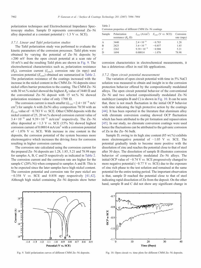
Table 2Corrosion properties of different CMM Zn–Ni coatings
Sample Polarizationresistance (Rp Ω)
Icorr (A/cm2) Ecorr (V vs. SCE) Corrosion
rate (mpy)
A 3440 2.4×10⁻⁶ −0.783 1.28B 2825 3.4×10⁻⁶ −0.857 1.85C 2262 9.39×10⁻⁶ −0.908 5.21D 1694 0.00014 −1.076 78.98
7902 P. Ganesan et al. / Surface & Coatings Technology 201 (2007) 7896–7904
polarization techniques and Electrochemical Impedance Spec-troscopy studies. Sample D represents conventional Zn–Nialloy deposited at a constant potential (−1.3 V vs. SCE).
3.7.1. Linear and Tafel polarization studiesThe Tafel polarization study was performed to evaluate the
kinetic parameters of the corrosion processes. Tafel plots wereobtained by varying the potential of Zn–Ni deposits by±200 mV from the open circuit potential at a scan rate of10 mV/s and the resulting Tafel plots are shown in Fig. 9. Theelectrochemical characteristics such as, polarization resistance(Rp), corrosion current (Icorr), corrosion rate (in mpy) andcorrosion potential (Ecorr) obtained are summarized in Table 2.The polarization resistance of the coatings increased with theincrease in the nickel content in the CMM Zn–Ni deposits sincenickel offers barrier protection to the coating. The CMM Zn–Niwith 30 wt.% nickel showed the highest Rp value of 3440Ω andthe conventional Zn–Ni deposit with 15 wt.% Ni showedpolarization resistance value of only 1700 Ω.
The corrosion current is much smaller (ICorr=2.4×10⁻⁶ mA/
cm2) for sample Awith Zn/Ni alloy composition 70/30 with anECorr value of −0.783 V vs. SCE. Other CMM deposits with thenickel content of 25, 20 wt.% showed corrosion current value of3.4×10−6 and 9.39×10⁻⁶ mA/cm2 respectively. The Zn–Nialloy deposited at −1.3 V vs. SCE (15% Ni) showed highestcorrosion current of 0.00014 mA/cm2 with a corrosion potentialof −1.076 V vs. SCE. With increase in zinc content in thedeposits, the corrosion potential of the system becomes moreelectronegative which increases the driving force for corrosionresulting in higher corrosion currents.
The corrosion rate calculated using the corrosion current forthe prepared Zn–Ni deposits are 1.28, 1.85, 5.21 and 78.98 mpyfor samples A, B, C and D respectively as indicated in Table 2.The corrosion current and the corrosion rate are higher for thesample C (20% Ni) when compared to samples A and B. This isto be expected since the later samples have high nickel content.The corrosion potential and corrosion rate for pure nickel are−0.358 V vs. SCE and 0.858 mpy respectively [41,42].Although high nickel containing Zn–Ni deposits show better
Fig. 9. Tafel polarization curves of different CMM Zn–Ni deposits.
corrosion characteristics in electrochemical measurements, ithas a deleterious effect in real life applications.
3.7.2. Open circuit potential measurementThe variation of open circuit potential with time in 5% NaCl
solution was measured to obtain and insight in to the corrosionprotection behavior offered by the compositionally modulatedalloys. The open circuit potential behavior of the conventionalZn–Ni and two selected compositionally modulated Zn–Nimultilayer (samples B and C) is shown in Fig. 10. It can be seenthat, there is not much fluctuation in the initial OCP behaviorwith time indicating the high protective action by the coatings[44]. It has been reported in the literature that aluminum alloywith chromate conversion coating showed OCP fluctuationwhich has been attributed to the pit formation and repassivation[45]. In our study, no chromate conversion coatings were usedhence the fluctuations can be attributed to the galvanic corrosionof Zn in the Zn–Ni bulk.
Sample D, owing to its high zinc content (85 wt.%) exhibitsmore electronegative potential of −1.05 V vs. SCE. Thepotential gradually tends to become more positive with thedissolution of zinc and reaches the potential close to that of steelafter 30 days. The dissolution of sample B illustrates corrosionbehavior of compositionally modulated Zn–Ni alloys. Theinitial OCP value of −0.74 V vs. SCE progressively changed tomore negative potential (−0.77 V vs. SCE) due to the exposureof zinc rich phase to the test solution and remained at the samepotential for the entire testing period. The important observationis that, sample D reached the potential close to that of steelindicating rapid dissolution of Zn from the deposit. On the otherhand, sample B and C did not show any significant change in
Fig. 10. Open circuit vs. time plots for different CMM Zn–Ni deposits.
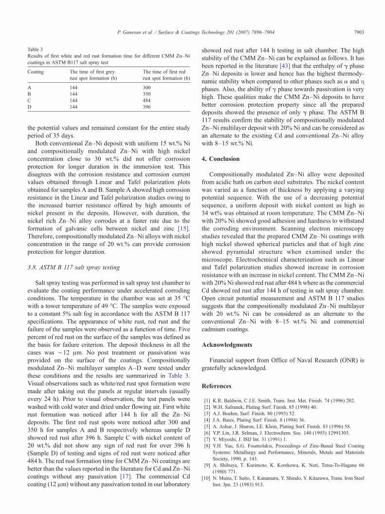
Table 3Results of first white and red rust formation time for different CMM Zn–Nicoatings in ASTM B117 salt spray test
Coating The time of first greyrust spot formation (h)
The time of first redrust spot formation (h)
A 144 300B 144 350C 144 484D 144 396
7903P. Ganesan et al. / Surface & Coatings Technology 201 (2007) 7896–7904
the potential values and remained constant for the entire studyperiod of 35 days.
Both conventional Zn–Ni deposit with uniform 15 wt.% Niand compositionally modulated Zn–Ni with high nickelconcentration close to 30 wt.% did not offer corrosionprotection for longer duration in the immersion test. Thisdisagrees with the corrosion resistance and corrosion currentvalues obtained through Linear and Tafel polarization plotsobtained for samples A and B. Sample A showed high corrosionresistance in the Linear and Tafel polarization studies owing tothe increased barrier resistance offered by high amounts ofnickel present in the deposits. However, with duration, thenickel rich Zn–Ni alloy corrodes at a faster rate due to theformation of galvanic cells between nickel and zinc [15].Therefore, compositionally modulated Zn–Ni alloys with nickelconcentration in the range of 20 wt.% can provide corrosionprotection for longer duration.
3.8. ASTM B 117 salt spray testing
Salt spray testing was performed in salt spray test chamber toevaluate the coating performance under accelerated corrodingconditions. The temperature in the chamber was set at 35 °Cwith a tower temperature of 49 °C. The samples were exposedto a constant 5% salt fog in accordance with the ASTM B 117specifications. The appearance of white rust, red rust and thefailure of the samples were observed as a function of time. Fivepercent of red rust on the surface of the samples was defined asthe basis for failure criterion. The deposit thickness in all thecases was ∼12 μm. No post treatment or passivation wasprovided on the surface of the coatings. Compositionallymodulated Zn–Ni multilayer samples A–D were tested underthese conditions and the results are summarized in Table 3.Visual observations such as white/red rust spot formation weremade after taking out the panels at regular intervals (usuallyevery 24 h). Prior to visual observation, the test panels werewashed with cold water and dried under flowing air. First whiterust formation was noticed after 144 h for all the Zn–Nideposits. The first red rust spots were noticed after 300 and350 h for samples A and B respectively whereas sample Dshowed red rust after 396 h. Sample C with nickel content of20 wt.% did not show any sign of red rust for over 396 h(Sample D) of testing and signs of red rust were noticed after484 h. The red rust formation time for CMMZn–Ni coatings arebetter than the values reported in the literature for Cd and Zn–Nicoatings without any passivation [17]. The commercial Cdcoating (12 μm) without any passivation tested in our laboratory
showed red rust after 144 h testing in salt chamber. The highstability of the CMM Zn–Ni can be explained as follows. It hasbeen reported in the literature [43] that the enthalpy of γ phaseZn–Ni deposits is lower and hence has the highest thermody-namic stability when compared to other phases such as α and ηphases. Also, the ability of γ phase towards passivation is veryhigh. These qualities make the CMM Zn–Ni deposits to havebetter corrosion protection property since all the prepareddeposits showed the presence of only γ phase. The ASTM B117 results confirm the stability of compositionally modulatedZn–Ni multilayer deposit with 20% Ni and can be considered asan alternate to the existing Cd and conventional Zn–Ni alloywith 8–15 wt.% Ni.
4. Conclusion
Compositionally modulated Zn–Ni alloy were depositedfrom acidic bath on carbon steel substrates. The nickel contentwas varied as a function of thickness by applying a varyingpotential sequence. With the use of a decreasing potentialsequence, a uniform deposit with nickel content as high as34 wt% was obtained at room temperature. The CMM Zn–Niwith 20% Ni showed good adhesion and hardness to withstandthe corroding environment. Scanning electron microscopystudies revealed that the prepared CMM Zn–Ni coatings withhigh nickel showed spherical particles and that of high zincshowed pyramidal structure when examined under themicroscope. Electrochemical characterization such as Linearand Tafel polarization studies showed increase in corrosionresistance with an increase in nickel content. The CMM Zn–Niwith 20%Ni showed red rust after 484 h where as the commercialCd showed red rust after 144 h of testing in salt spray chamber.Open circuit potential measurement and ASTM B 117 studiessuggests that the compositionally modulated Zn–Ni multilayerwith 20 wt.% Ni can be considered as an alternate to theconventional Zn–Ni with 8–15 wt.% Ni and commercialcadmium coatings.
Acknowledgments
Financial support from Office of Naval Research (ONR) isgratefully acknowledged.
References
[1] K.R. Baldwin, C.J.E. Smith, Trans. Inst. Met. Finish. 74 (1996) 202.[2] W.H. Safranek, Plating Surf. Finish. 85 (1998) 40.[3] A.J. Boehm, Surf. Finish. 80 (1993) 52.[4] J.A. Bates, Plating Surf. Finish. 8 (1994) 36.[5] A. Ashur, J. Sharon, I.E. Klein, Plating Surf. Finish. 83 (1996) 58.[6] Y.P. Lin, J.R. Selman, J. Electrochem. Soc. 140 (1993) 12991303.[7] Y. Miyoshi, J. ISIJ Int. 31 (1991) 1.[8] Y.H. Yau, S.G. Fountolakis, Proceedings of Zinc-Based Steel Coating
Systems: Metallurgy and Performance, Minerals, Metals and MaterialsSociety, 1990, p. 143.
[9] A. Shibuya, T. Kurimoto, K. Korekewa, K. Noti, Tetsu-To-Hagane 66(1980) 771.
[10] N. Muira, T. Saito, T. Kanamaru, Y. Shindo, Y. Kitazawa, Trans. Iron SteelInst. Jpn. 23 (1983) 913.

7904 P. Ganesan et al. / Surface & Coatings Technology 201 (2007) 7896–7904
[11] M.R. Lambert, R.G. Hart, H.E. Townsend, Proc. 2nd Automot. Corr. Prev.Conf., 1983, p. 81.
[12] W.H. Safranek (Ed.), The Properties of Electrodeposited Metal and Alloy,AESF, Orlando, FL, 1986, p. 466.
[13] A. Brenner, Electrodeposition of Alloys, Principles and Practice, Chap. 1,Academic Press, New York, 1963.
[14] N.S. Grigoryan, V.N. Kudryavtsev, P.A. Zhdan, I.Y. Kolotyrkin, E.A.Volynskaya, T.A. Vagramyan, Zas. Met. 25 (1989) 288.
[15] D.E. Hall, Plating Surf. Finish. 70 (1983) 59.[16] K. Higaashi, H. Fukushima, T. Urakawa, T. Adaniya, K. Matsudo, J.
Electrochem. Soc. 128 (1981) 2081.[17] M. Pushpavanam, S.R. Natarajan, K. Balakrishnan, L.R. Sharma, J. Appl.
Electrochem. 21 (1991) 642.[18] F.J. Fabri Miranda, I.C.P. Margarit, O.R. Mattos, O.E. Barcia, R. Wiart,
Corrosion 55 (1999) 732.[19] M.R. Kalantary, Plating Surf. Finish. 81 (1994) 80.[20] X.G. Zhang, J. Electrochem. Soc. 143 (1996) 1472.[21] A.M. Alfantazi, G. Brehaut, U. Erb, Surf. Coat. Technol. 89 (1997) 239.[22] G.D. Wilcox, JCSE, J. Corros. Sci. Eng. 6 (2004) Paper No. 52.[23] A. Krishniyer, M. Ramasubramanian, B.N. Popov, R.E. White, Plating
Surf. Finish. 87 (1999) 99.[24] A. Durairajan, A. Krishniyer, B.N. Popov, B. Haran, S.N. Popov,
Corrosion 56 (2000) 283.[25] B. Veeraraghavan, H. Kim, B. Haran, B. Popov, Corrosion 59 (2003) 1003.[26] B. Veeraraghavan, H. Kim, B. Haran, B. Popov, Electrochim Acta 49
(2004) 3143.[27] Z. Zhou, T.J.O. Keefe, Surf. Coat. Technol. 96 (1997) 191.[28] C. Savall, C. Rebere, D. Sylla, M. Gadouleau, Ph. Refait, J. Creus, Mater.
Sci. Eng., A Struct. Mater.: Prop. Microstruct. Process. 430 (2006) 165.
[29] N. Boshkov, K. Petrov, G. Raichevski, Surf. Coat. Technol. 200 (2006)5995.
[30] N. Boshkov, Surf. Coat. Technol. 172 (2003) 217.[31] V. Ivanova, G. Raichensky, St. Vitkova , M. Nikolova, Surf. Coat. Technol.
82 (1996) 232.[32] L. Sziraki, A. Cziraki, Z. Vertesy, L. Kiss, V. Ivanova, G. Raichevski, S.
Vitkova, J. Appl. Electrochem. 29 (1999) 927.[33] G. Roventi, R. Fratesi, R.A. Della Guardia, G. Barucca, J. Appl.
Electrochem. 30 (2000) 173.[34] F. Elkhatabi, M. Benballa, M. Sarret, C. Muller, Electrochim. Acta. 44
(1999) 1645.[35] J.B. Bajat, V.B. Miskovic-Stankovic, Prog. Org. Coat. 49 (2004) 183.[36] M.M. Abou-Krisha, A.M. Zaky, A.A. Toghan, JCSE, J. Corros. Sci. Eng. 7
(2005) 1.[37] M.M. Abou-Krisha, Appl. Surf. Sci. 252 (2005) 1035.[38] G. Barcelo, J. Garcia, M. Sarret, C. Muller, J. Appl. Electrochem. 24
(1994) 1249.[39] D.H. Lee, S.H. Park, Anal. Sci. Technol. 12 (1999) 40.[40] C. Muller, M. Sarret, E. Garcia, J. Electrochem. Soc. 150 (2003) C212.[41] Hansung Kim, Branko N. Popov, Ken S. Chen, Corros. Sci. 45 (2003)
1505.[42] Anand Durairajan, Bala S. Haran, Ralph E. White, Branko N. Popov, J.
Electrochem. Soc. 147 (2000) 1781.[43] Z.L. Wang, Y.X. Yang, J.B. Zhang, H. Zhu, Y.R. Chen, J. Electrochem. 42
(2006) 22.[44] C. Muller, M. Sarret, E. Garcia, J.A. Ortega, J. Electrochem. Soc. 151
(2004) C149.[45] G.O. Ilevbare, J.R. Scully, J. Yuan, R.G. Kelly, Corrosion (Houst., Tex.) 56
(2000) 227.