development of durable ceramic matrixdevelopment of ... turbine components for advanced propulsion...
TRANSCRIPT

Development of Durable Ceramic MatrixDevelopment of Durable Ceramic MatrixDevelopment of Durable Ceramic Matrix Composite Turbine Components for Advanced
Propulsion Engine Systems
Development of Durable Ceramic Matrix Composite Turbine Components for Advanced
Propulsion Engine SystemsPropulsion Engine Systems Propulsion Engine Systems
Dongming Zhu
Durability and Protective Coatings BranchStructures and Materials Division
NASA John H. Glenn Research CenterNASA John H. Glenn Research CenterCleveland, Ohio 44135, USA
1
8th Pacific Rim Conference on Ceramic and Glass TechnologyVancouver, May 31-June 5, 2009

Revolutionary Ceramic Coatings and Composites Greatly Impact Turbine Engine TechnologyImpact Turbine Engine Technology
— Ceramic thermal/environmental barrier coating (T/EBC) and ceramic matrix composite (CMC) development goals- Meet engine temperature and performance requirements- Ensure long-term durability- Develop design tools and lifing methodologies- Improve technology readiness
— Crucial for envisioned supersonic vehicles: reduced engine emission, improved efficiency and long-term supersonic cruise durability
2

Revolutionary Ceramic Coatings and Composites Greatly Impact Turbine Engine Technology - ContinuedImpact Turbine Engine Technology Continued
3000°F+ (1650°C+)
Temperature Capability (T/EBC) surface
Temperature Capability (T/EBC) surface
Step increase in the material’s temperature capability3100°F SiC/SiC
CMC combustor
2700°F SiC/SiC CMC2800ºF combustor
Increase in T across T/EBCIncrease in T across T/EBC
2700°F (1482C)2700 F SiC/SiC CMC
turbine systemcombustor TBC
2500ºF Turbine TBC
2400°F (1316°C)
Gen IV
Single Crystal Superalloy
Ceramic Matrix Composite
Gen IV
Single Crystal Superalloy
Ceramic Matrix Composite
2000°F (1093°C)
Gen I
Gen II – Current commercialGen III
Gen. IV
YearGen I
Gen II – Current commercialGen III
Gen. IV
Year
3

MOTIVATION— Thermal and environmental barrier coatings with advanced hot-section
substrate component materials help increase gas turbine operating temperatures, reduce cooling requirements, improve engine fuel efficiency and
li bilitreliability— Prime-reliant coating system is key to engine component durability
Combustor Vane Blade Ceramic nozzles
Temperature increaseincrease
Turbine
CMC combustor liner , vane/blade
4
(a) Current TEBCs (b) Advanced T/EBCs
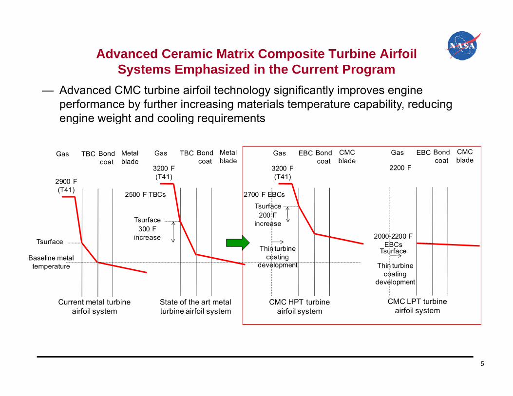
Advanced Ceramic Matrix Composite Turbine Airfoil Systems Emphasized in the Current ProgramSystems Emphasized in the Current Program
— Advanced CMC turbine airfoil technology significantly improves engine performance by further increasing materials temperature capability, reducing engine weight and cooling requirementsg g g q
Gas TBC Bond coat
Metal blade
3200 F
Gas TBC Bond coat
Metal blade
3200 F
Gas EBC Bond coat
CMC blade
2200 F
Gas EBC Bond coat
CMC blade
2900 F(T41)
(T41) (T41)
Tsurface200 F
increase
Tsurface
2500 F TBCs 2700 F EBCs
Baseline metal temperature
300 FincreaseTsurface
increase
Thin turbine coating
development
Tsurface
2000-2200 F EBCs
Thin turbine coating
Current metal turbine airfoil system
State of the art metal turbine airfoil system
CMC HPT turbine airfoil system
CMC LPT turbine airfoil system
coating development
5

Outline
─ Research & development emphases and thrust areas
Hi h h fl i h d f CMC bi i f il─ High heat flux testing methods for CMC turbine airfoil development
─ Thermal and environmental barrier coatings systemsThermal and environmental barrier coatings systems development
─ Design tool and life prediction of coated CMC components
─ Summary and future directions
6

Research and Development Emphases and Thrust Areas (continued)(continued)
Advanced coating and CMC development and processingSimulated engine heat-flux testing for coated component design and process validation
Ad d i t l
High heat-flux thermal gradient mechanical testing and simulated engine testing of coated CMC specimens and subcomponents
Advanced environmental barrier coating development Embedded
TC Temperature
3D Orthogonal
2D Five-harness Satin
SiC/BN nanotube () synthesis for
Angle Interlock
Braid
7
SiC/BN nanotube () synthesis for nano-composite coating
applications
Embedded thermocouple and heat flux sensor developmentCMC fiber architecture design
and property modeling

Research and Development Emphases and Thrust Areas (continued)(continued)
Development of physics-based design tools and computational life models
FEA S lMaterials and
systemsAdvanced testing-
simulatingFEA Solver
Atomistic and i h i
Physical process d l d l
systemsDatabase
Mechanisms-i
simulating module
Continuum and lmicro-mechanics
models modulemodels module environment
interaction module
structural mechanics
module
Design Tool and Life Prediction
Test rigTC
g
Design tool development for coated CMCSimulated high pressure and high
8
Design tool development for coated CMC turbine components
Simulated high pressure and high velocity combustion flow and CMC
turbine airfoil for heat transfer modeling

High-Heat-Flux Test Approaches– Turbine level high-heat-flux tests crucial for CMC coating system developments
• High power CO2 laser high-heat-flux rig (up to 315 W/cm2)
Heat flux
Turbine: 450°F across 100 microns Combustor:1250°F across 400 microns
T
rom
sur
face
Dis
tanc
e fr
Test rig
cooling
Test rig
9

Thermal Conductivity Measurement by a Laser High-Heat-Flux ApproachFlux Approach
Where )(/)( tTlqtk ceramicceramicthruceramic radiatedreflecteddeliveredthru qqqq
substratebond l
substrate
thrul
bond
thrubackmetalsurafceceramicceramic Tk
dlqTkdlqTTtT
00 )()()(and
8 m pyrometer for Tceramic-surface
radiatedqreflectedq
deliveredq
ceramic coatingbond coat
TT
thruq
b t t
bondsubstrate
measuredceramic
TTTT
Ttc
Two-color and 8 m pyrometers for
Optional miniature thermocouple for
thruq
substratetc
10
Tsubstrate-back additional heat-flux calibration
thruq

Laser Heat Flux Testing in Water Vapor Environments for High Temperature SiC/SiC Ceramic Matrix CompositesHigh Temperature SiC/SiC Ceramic Matrix Composites
─ High temperature and high-heat-flux testing capabilities─ “Micro-steam environment” allowing high water vapor pressure, relatively high
velocity under very high temperature conditionvelocity under very high temperature condition
- Steam injected at up to 5m/sec- Testing temperature >1700°C
11
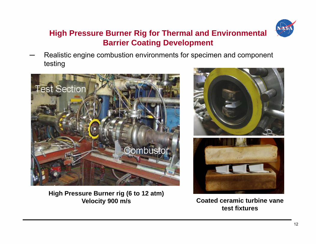
High Pressure Burner Rig for Thermal and Environmental Barrier Coating DevelopmentBarrier Coating Development
─ Realistic engine combustion environments for specimen and component testing
High Pressure Burner rig (6 to 12 atm)V l it 900 / C t d i t bi
12
Velocity 900 m/s Coated ceramic turbine vane test fixtures

Thermal Conductivity of EBC Material Systems
– Thermal conductivity of plasma-sprayed HfO2-(Y,Gd/Nd,Yb)2O3 systems determined using laser heat flux approaches
1.5 2.51.5
1.0
cond
uctiv
ity, W
/m-K
Tsurface=~3000°F1.0
1.5
2.0
con
duct
ivity
, W/m
-K
1.0
cond
uctiv
ity, W
/m-K
~k0
0.0
0.5
0.0 5.0 10.0 15.0 20.0
Ther
mal
c
Time, hours
Tsurface=~3000 FTinterface=~2012°F
0.0
0.5
1000 1100 1200 1300 1400 1500
k20k0k20 predicted
Ther
mal
Average temperature, °C
0.0
0.5
1000 1100 1200 1300 1400 1500 1600 1700 1800
<k20><k0>k(T) predicted
Ther
mal
cTemperature, °C
Time, hours
1 2
1.4
1.6
k0k20
y, W
/m-K
0.8
1.0
1.2
Ther
mal
con
duct
ivity
Possible optimum regionLow
durability Higher conductivity
13
0.6
10 12 14 16 18 20 22
T
Total dopant concentration, mol%
Possible optimum regionyregion conductivity
region

High-Heat-Flux Thermal Gradient Cyclic Testing of EBC Material SystemsMaterial Systems
– Coating degradation modes can be monitored in real time
1.5
2.0
1200
1600Normalized kcera
ctiv
ity, W
/m-K
C
1.5
2.0
1500
2000Normalized k
ctiv
ity, W
/m-K
C
0 5
1.0800
1200
Tsurfaced th
erm
al c
ondu
c
Tem
pera
ture
, °
0 5
1.0
500
1000
d th
erm
al c
ondu
c
Tem
pera
ture
, °
0.0
0.5
0
400
0 5 10 15 20 25
TinterfaceTback
Nor
mal
ized
Ti h
0.0
0.5
0
500
0.0 2.0 4.0 6.0 8.0 10.0
TsurfaceTinterfaceTback
Nor
mal
ized
Ti hTime, hours Time, hours
14

Interface Reactions of Baseline Coating in Heat Flux and Water Vapor Cyclic EnvironmentsWater Vapor Cyclic Environments
— Significant interfacial pore and eutectic phase formation due to the water vapor attack and Si diffusion under the thermal gradient cycling conditions at interface temperature 1300°C
ZrO2-8wt%Y2O3ZrO2-8wt%Y2O32 % 2 3
Mullite+BSAS
Si
2 % 2 3
Mullite+BSAS
SiSiSiC/SiC
SiSiC/SiC
BSAS MulliteBSAS Mullite MulliteBSAS
SiSi
15
Si

Sintering and Creep Induced Failure of TEBCs
― Models used to predict long-term sintering behavior from sintering data― Variable sintering rates observed
- Initially very fast sinteringy y g- Reduced sintering rates with increasing time
― Sintering-creep can induce surface cracking and delamination
1200°C-e%1300°C-e%1400°C-e%
1200°C-de/dt1300°C-de/dt1400°C-de/dt 0.0 200
ZrO2-8wt%Y2O3/Mullite+BSAS/Si SystemPlasma-sprayed ZrO2-8wt%Y2O3
0 0
0.5
1.0
1.5
-5.0 10-9
0.01500°C-e% 1500°C-de/dt
in e
=DL/
L, %
t, 1/
sec -0.4
-0.2150
train
s, %
e ra
te, J
/m2
thruC
G 1500mindelaC
G 1500
-1.5
-1.0
-0.5
0.0
-1.5 10-8
-1.0 10-8
ring
shrin
kage
stra
i
Stra
in ra
te-d
e/dt
-1.0
-0.8
-0.6
50
100
Shrik
age
st
Ener
gy re
leas
G
ETBC
~60GPathru
CG 1400
mindelaG
16
-2.5
-2.0
-2.0 10-8
0 100 200 300 400 500 600
Sint
e
Time, hours
-1.2 00 5 10 15 20
Time, hours
GC
mindelaC
G 1400

Advanced Coating System Development
— Mutli-component zirconia/hafnia-, perovskite and pyrochlore-oxide-based systems as high stability top coats for ceramic components: defect cluster coating concept demonstrated
• Rare earth dopants for improved thermal stability• Transition metal dopants for phase stability and temperature capability of EBCs• Thin coating configurations emphasized for turbine applicationThin coating configurations emphasized for turbine application
— Low stress, strain tolerant interlayer and high strength bond coat concepts• Advanced modified HfO2-aluminosilicates show high performance
– Nano composite structures– Controlled thermal conductivity and thermal expansion– Controllable Si activity suitable for improved bonding and stability
• Novel compositional and architectural design to achieve maximum energy dissipationNovel compositional and architectural design to achieve maximum energy dissipation and durability – Alternating composition layered coating (ACLC) concept demonstrated– Temperature Actuation Coating (TAC) systems
17
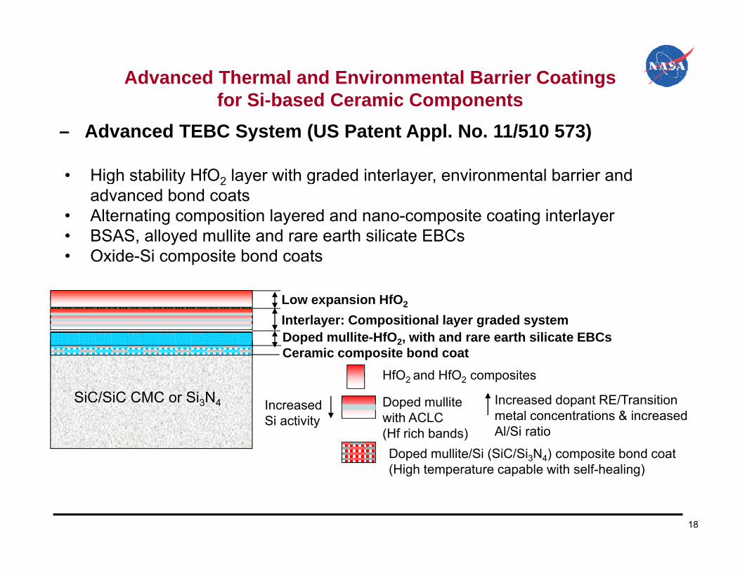
Advanced Thermal and Environmental Barrier Coatings for Si-based Ceramic Components
– Advanced TEBC System (US Patent Appl. No. 11/510 573)for Si based Ceramic Components
• High stability HfO2 layer with graded interlayer environmental barrier andHigh stability HfO2 layer with graded interlayer, environmental barrier and advanced bond coats
• Alternating composition layered and nano-composite coating interlayer• BSAS, alloyed mullite and rare earth silicate EBCs
O id Si i b d• Oxide-Si composite bond coats
Interlayer: Compositional layer graded systemLow expansion HfO2
Doped mullite-HfO2, with and rare earth silicate EBCsCeramic composite bond coat
Interlayer: Compositional layer graded system
SiC/SiC CMC Si NHfO2 and HfO2 composites
SiC/SiC CMC or Si3N4 Doped mullitewith ACLC (Hf rich bands) Doped mullite/Si (SiC/Si3N4) composite bond coat(Hi h t t bl ith lf h li )
Increased Si activity
Increased dopant RE/Transition metal concentrations & increased Al/Si ratio
18
(High temperature capable with self-healing)

Advanced Thermal and Environmental Barrier Coatings for Si-based Ceramic Components
– Advanced HfO2-Rare Earth Aluminosilicate composite coatings synthesized for improved long-term durability
for Si based Ceramic Components
19

Advanced TEBCs Integrated CMCs
– Ceramic-nanotube composite bond coats with optimized CMC systems for high performance complex engine components
warp
fillL= length
warp
fillL= length
warp
fillL= length
X1, Z2 X2, Z2X1, Z2 X2, Z2
TGA Data in Air
90100110
Improved SiCNT yield during conversion reaction from 50% to 65 %
SiCNT retained nanotube morphologyfollowing heat in air to 1200°C
Improvement
W = width
H = height
t =thickness
W = width
H = height
t =thickness
W = width
H = height
t =thickness
1020304050607080
Mas
s C
hang
e (%
) SiCNT
MWCNT
SiCNT Improvedconversion
Improvement in conversion
10 1600
X1, Z1 X2, Z1X1, Z1 X2, Z1
Fiber architecture modeling to optimize fiber contents and structures and improve the complex-shaped blade strength
010
0 200 400 600 800 1000 1200
Temperature (C)
MWCNT startingmaterial
4
6
8
800
1200
TsurfaceTinterfaceTback
cond
uctv
ity, W
/m-K
empe
ratu
re, °
C
0
20
400
0 20 40 60 80 100 120
kcera
Ther
mal
Te
Time, hours
1 hr cycles, in air
20
After testingThermal gradient cyclic testing of Mullite-
SiCNT composite coating on SiC/SiC

Laser High-Heat-Flux Thermal Fatigue Testing of CMC under Simulate Turbine Blade Temperature Gradients and
St E i tStress Environments
200
300
coating
1.6 in
0
100
200
ess,
MPa
coating
-200
-100
Stre
Specimen testing
-3000 0.5 1 1.5 2 2.5
Distance from surface, mm
Stress rupture and low cycle fatigue life i ti t d f t d d t d
21
Coated CMC temperature modeling
investigated for coated and uncoated CMC systems

Laser High-Heat-Flux Thermal Fatigue Testing of CMC under Simulate Turbine Blade Temperature Gradients and
St E i t C ti dStress Environments- Continued- Laser high heat flux tensile fatigue test rig allows very high temperature, high heat flux thermal gradient testing under turbine blade stress conditions
22

Advanced Low Pressure Plasma Spray Thin Film and Physical Vapor Deposition (LPPS-TF and LPPS-PVD) for
CMC Ai f il C ti P iCMC Airfoil Coating Processing─ Advanced hybrid plasma-vapor deposition thin film coating technologies are
currently being pursued for CMC turbine blade coating processing
Conventional air plasma-spray (APS) processing of environmental barrier coatings
Low pressure plasma-spray (LPPS)
Hybrid LPPS-TF and LPPS-PVD coater under
construction
23
construction

Environmental Barrier Coating and Embedded Sensor Development for Component Health MonitoringDevelopment for Component Health Monitoring
― High temperature harsh environment embedded temperature/heat flux sensors for coated SiC/SiC ceramic matrix composite (CMC) turbine engine components are being developedcomponents are being developed
Laser high heat-flux rig High pressure burner rig
Mach 0.3 Burner RigA heat flux sensor on an environmental barrier coating (EBC)-CMC specimen
24
Embedded sensor testing and validation in simulated engine environments

The 3100°F SiC/SiC CMC Turbine Vane Coating Systems
— The coating system successfully completed total 100, 1 hr cycle laser heat flux 3100°F test (60min hot, 3min cool)
Top layerTsurfaceTinterface
Interlayer
Top layer
EBC3 0
3.5
4.0
1600
kcera Tback
W/m
-K
3100°F coatings3100°F coatingsEBCSi bond coat
1 5
2.0
2.5
3.0
800
1200
ondu
ctiv
ity, W
mpe
ratu
re, °
C
0 0
0.5
1.0
1.5
0
400
Ther
mal
c Tem
25
After testing0.0 0
0 20 40 60 80 100 120Time, hours

The Long-Term Durable CMC Turbine Blade Coating System Testing under High Heat Flux Conditions
— Coating successfully tested at Tsurface 2700°F and Tinterface 2400°F for 250 hrs (60min heating, 5min cooling cycles)
System Testing under High Heat Flux Conditions
Thin coating turbine CMC demonstrated high-heat-flux
26
gcyclic durability at 2700˚F

Radiative Diffusion Models for Non-Gray Materials
- The diffusion conduction models established for non-gray coating materials to understand complex thermal conductivity behavior
scond
scondtotal dx
dTa
Tnk
dxdT
aTn
dxdTkq
aveave
316
316 3232
- The diffusion conduction equations
Gray model
radconds
condeffective kka
Tnkk
ave
3
16 32condk Intrinsic lattice conductive thermal conductivity
8 2 4
radk radiation thermal conductivity
totalq Total heat flux
effectivek effective thermal conductivity T(d)T(0)FFTn16σkq3ave
2
Gray model
n
a
s
T
Stefan-Boltzman constant 5.6704x10⁻⁸ W/(m2-K4)
Refractive index, 2.2Absorption coefficient, cm-1
Scattering coefficient, cm-1
Average temperature of the material, K
d
FF3κ
kqavestaveop Tλ0Tλ0total
1n32
23
nς
4λT0 n6
n6ς
n3ςς
ne
π15F
Non-Graymodel
1rq 2rq
opaqueRadiativediffusion
approximationtransparent
0
opaqueRadiativediffusion
approximationtransparentopaque
Radiativediffusion
approximationtransparent
0
1rq
1sT1gT
2gTD
27
Regions of optical thicknessc10 c2
Regions of optical thicknessc10 c2

Radiative Diffusion Model Validation for Coating Systems
2 5
3.0
m-K 0.8
1.00.0 0.50 1.0 1.5 2.0
ratio
n I/I
0
scattering-
absorption
Coating thickness, mm
2.0
2.5
vity
, W/m
0.2
0.4
0.6
B likbod
y ra
diat
ion
pene
tr scatteringbaseline coatings
scattering-advanced coatings
1.5
cond
uctiv
Radiation component0.0
0 500 1000 1500 2000
BaselinesAdvanced coatingsB
lack
Coating thickness, microns
0 5
1.0
Ther
mal
c
0.0
0.5
200 400 600 800 1000 1200 1400 1600 1800
T
28
200 400 600 800 1000 1200 1400 1600 1800Surface temperature, °C

High Pressure Burner Rig Durability Evaluations
― High velocity nozzle designed to improve heat flux under high pressure condition― Optimum heat flux regime determined
200 1000
160
180800Heat flux
Chamber pressureGas velocity
ty, m
/s
140
160
600flu
x, W
/cm
2
re; p
si; g
as v
eloc
it
100
120
200
400Hea
t
Cha
mbe
r pre
ssu r
60
80
010 15 20 25 30 35 40
29
Pressure difference in combustor and test chamber, psi

High Pressure Burner Rig Durability Evaluations(Continued)(Continued)
― High Pressure Burner Rig Stability being evaluated for TEBCs on SiC/SiC― High stability coatings being downselected
1AS800SN2822 -h
1300Temperature, °C
14001500 12001600
SiC/SiC under high velocity
0.1
SiC/SIC CMCLa
2Hf
2O
7
HfO2 (doped)
RE-Hf-luminosilicatesBSASan
ge, m
g/cm
2
0.01
c w
eigh
t cha Rare earth silicates
BSAS Baseline
0.0010 0005 0 00055 0 0006 0 00065 0 0007 0 00075 0 0008
Spec
ific
Future EBC stability development goal
30
0.0005 0.00055 0.0006 0.00065 0.0007 0.00075 0.00081/T, K-1

Physics-Based Life Prediction Models and Design Tools for Advanced EBC-Coated CMC Material Systemsfor Advanced EBC Coated CMC Material Systems
– Heat transfer and stress models developed for various EBC coated specimen configurations
– Fracture-mechanics based component life prediction approaches emphasized for blade applications
0 .5 8 4 2 m m
E B C C ra c k
C ra c k d e p th , a
M
M M M
O2+H2O(g)
M
M M M
O2+H2O(g)
M
M M M
O2+H2O(g)
M
M M M
O2+H2O(g)
S i
E B CT B C
W
2 m m
0 .1 2 7 m m0 -0 .5 0 8 m m
0 .6 3 5 -0 .1 2 7 m m
0 .0 7 8 7 4 in
5 m ils0 -2 0 m ils
2 5 -5 m ils
C M C
2 C
Quarter Section of a coated CMC Tubular specimen12.7 mm outer diameter2.0 mm tube thickness
0.127 mm coating thickness
Laser heat flux Heating
Pores Cracks
Pores Cracks
W
EBC coated CMC crack configuration
2.5
3.0
3.5
a m
0.5 tTB C=0 .381m m
tEBC =0.254m mE = 10GPa
T BC Crack
Mesh Steady-State Temperature profileMulti-mechanisms Interactions
-1.5
-1.0
-0.5
0.0
0.5
1.0
1.5
2.0
0 1 2 3 4
C rack Length a , m m
Stre
ss In
tens
ity F
acto
r K, M
P
M od e IM od e IIM ixed M o de
ET BC= 10GPa
Gradient
Co nstant
T em perature
8 000 RPM
Subcomponent modeling
31
2sin
2cos3
2cos 23 mm
IIm
Ieff KKK
Max. Principal Stress Criterion
Failure driving force as a surface crack length Hollow CMC Blade 2mm wall thickness
8,000 RPM
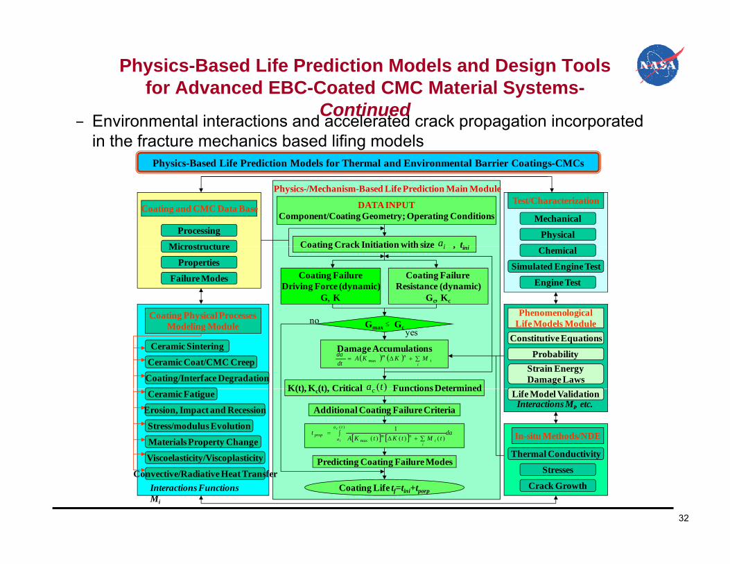
Physics-Based Life Prediction Models and Design Tools for Advanced EBC-Coated CMC Material Systems-
C ti dContinued – Environmental interactions and accelerated crack propagation incorporated in the fracture mechanics based lifing models
Physics-Based Life Prediction Models for Thermal and Environmental Barrier Coatings-CMCs
DATA INPUTComponent/Coating Geometry; Operating Conditions
Coating Crack Initiation with size , ti i
Physics-/Mechanism-Based Life Prediction Main Module
Processing
Microstructure
Mechanical
Physicalia
Test/CharacterizationCoating and CMC Data Base
Coating FailureDriving Force (dynamic)
GK
Coating Failure Resistance (dynamic)
GcKc
Coating Physical Processes
Coating Crack Initiation with size , tiniMicrostructure
Properties
Failure Modes
Chemical
Simulated Engine Test
Engine Test
i
PhenomenologicalGmax Gc
Damage Accumulations
Coating Physical Processes Modeling Module
Coating/Interface Degradation
Ceramic Sintering
Ceramic Coat/CMC Creep i
inm MKKA
dtda
max
yesno
K(t) K (t) Critical Functions Determined)(ta
Constitutive Equations
ProbabilityStrain EnergyDamage Laws
gLife Models Module
Stress/modulus Evolution
datMtKtKA
tta
ai
inmprop
c
i
)(
max )()()(1
Ceramic Fatigue K(t), Kc(t), Critical Functions Determined)(tac
Additional Coating Failure Criteria
P di ti C ti F il M dThermal Conductivity
Erosion, Impact and Recession
In-situ Methods/NDE
Interactions Mi, etc.Life Model Validation
Materials Property Change
Viscoelasticity/Viscoplasticity
32
Interactions Functions Mi
Convective/Radiative Heat TransferCoating Life tf=tini+tporp
Predicting Coating Failure Modes
Crack Growth
StressesViscoelasticity/Viscoplasticity

Summary
• Advanced ceramic turbine component testing capabilities established
• High stability thermal and environmental barrier coatings developed
• Advanced hybrid plasma-vapor deposition being developed for complex-h d t d ith thi ti fi tishaped components and with thin coating configurations
• Coated CMC stability demonstrated in high velocity-high pressure burner rig simulated engine environmentsrig simulated engine environments
• Coated CMC systems demonstrated initial low cycle fatigue and thermomechanical fatigue durabilitythermomechanical fatigue durability
• Heat transfer, fracture mechanics and stochastic approaches being established to develop coated CMC life prediction models
33
established to develop coated CMC life prediction models
Future Directions• High stability thin coatings system development
– Emphasize advanced processing and composites
• Coatings with significantly improved thermal and mechanical load capability
• Materials and component system integration– Enhanced functionality with embedded sensors and self-healing capability
• Laboratory simulated high heat flux stress testing and life prediction methodology development
34

AcknowledgementsThe work was supported by NASA Fundamental Aeronautics
Program.
35