development of dynamic stability criteria from direct ...€¦ · development of dynamic stability...
TRANSCRIPT

Development of Dynamic Stability Criteria from Direct Seakeeping Simulations
Stefan Krueger1 and Florian Kluwe2
ABSTRACT Recent investigations have shown a demand for the introduction of additional criteria to the IMO-intact stability code, accounting for dynamic phenomena related to the behavior of ships in rough weather. The general need for such kind of criteria arises because modern ship designs suffer from specific phenomena in rough weather which were not as relevant for those designs relevant at the time the intact stability code was developed. This paper suggests a structure for these dynamic criteria. Within this proposed structure, one set of criteria will account for a minimum stability limit required to ensure that these standards will provide the ships with sufficient safety. For the development of this proposed set of criteria, validated tools and procedures are used that have been successfully used for ship designs with sufficient safety on one hand and without any competitive disadvantage on the other hand.
KEY WORDS Stability criteria; Intact Stability, Seakeeping Performance
PROPOSED STRUCTURE OF THE CRITERIA When the operation of ships in heavy weather is considered, the following dangerous situations may occur:
• pure loss of stability, typically on a wave crest; • parametric rolling; • excessive roll moments introduced to the ship; • cargo shift or other heeling moments; and • broaching.
These conditions typically happen in a sea state under the influence of arbitrary loads, which might come from wind and waves. The nature of these phenomena is purely dynamic, and therefore, the approach to tackle these phenomena must be a dynamic approach. Following a performance based concept, intact stability should then cover the following issues:
• sufficient ability of the ship to withstand dynamic heeling moments in a sea state; • low heeling angles and low accelerations in operating conditions; • avoidance of critical resonances in operating range (making dangerous situations less probable); • sufficient roll damping, especially for ships with large mass moments of inertia; and • sufficient course keeping and steering ability for safe operation in heavy weather.
The related stability criteria then should focus on the avoidance of large rolling angles and on the avoidance of large accelerations. In this context, a large rolling angle is defined as a rolling angle which may lead either,
• to the capsizing of the vessel, • to the submergence of major non weather tight openings, • to the malfunctioning of an important system, • to severe cargo shift, or • to any situation which will cause an even larger rolling angle.
__________________________ 1 TU Hamburg-Harburg, Germany 2 TU Hamburg-Harburg, Germany

A large rolling angle is, therefore, an event which may lead to the total loss of the vessel. A large acceleration is defined as any acceleration which causes,
• massive cargo loss, • severe damage to machinery or major safety relevant systems, • structural overload of safety relevant members, or • severe discomfort or injuries to passengers or crew.
A large acceleration is, therefore, an event which may result in severe damage to the ship but not necessarily in a total loss. It is important to note that large rolling angles are not necessarily accompanied by large accelerations and also large accelerations can occur at relatively small rolling angles. Furthermore, depending on the stability values of the ship, the same sea state, course and speed settings may either result in large rolling angles, or large accelerations, or both. Large accelerations typically occur at high values of initial GM and, therefore, criteria are necessary to limit the stability accordingly (maximum GM limits). Large rolling angles can occur either at low values of initial GM or during broaching situations. As broaching phenomena are related to coursekeeping problems in heavy weather, broaching can hardly be avoided by modifying the GM value of the ship. Broaching is a manoeuvring problem and must be treated accordingly. In all other cases the avoidance of large rolling angles coincides with the establishment of minimum GM limits. If the roll damping is not sufficient, large rolling angles may also occur in a beam sea condition at zero speed (dead ship) if a resonance is met. From all these findings and related design experience, the dynamic criteria to be developed may have the following structure:
• criteria to avoid large rolling angles (Minimum Stability requirement); • criteria to avoid large accelerations (Maximum Stability limit); • criteria to guarantee sufficient roll damping in dead ship condition (Minimum Damping requirement); and • criteria to avoid broaching (Minimum Course keeping limit).
The following sections deal with the detailed investigations of possible criteria to ensure a minimum intact stability limit based on a dynamic evaluation of ships in rough weather.
INTRODUCTION TO PARAMETRIC ROLLING AND PURE LOSS OF STABILITY
Description of the Relevant Phenomena Pure loss of stability and parametric rolling are the relevant phenomena which can be related to large rolling angles, provided the roll damping is sufficient. Both phenomena are closely connected to large alterations of the righting levers between stillwater, crest and trough conditions. Although this has been known for more than fifty years, it became a serious problem when the first ships with large barge-type aftbodies and V-shaped frames in the forebody accompanied by large flare were introduced. Figure 1 may indicate what happens to such kind of ships in waves:
• in the crest condition, the aftbody is significantly out of water which results in significant loss of stability, and • in the trough condition, the ship has excessive stability due to the high form stability of the forebody.
Figure 1: Righting Levers in Stillwater, Crest and Trough Condition

When the stability loss on the crest exceeds a certain limit, the vessel may have no stability left at all and capsize if it rests in this crest condition for a certain time (pure loss of stability). In cases where some stability is left and the correct frequency is met, the ship is rightened up at maximum heel which coincides with the trough condition (because the righting lever is excessively high) and is heavily heeled in the upright position where the crest is at about LbP/2 (because the crest lever is extremely reduced). A rolling motion is observed that can lead to a capsize, if heeling/righting moments take a critical value and/or damping is too low (parametric rolling). These effects become most pronounced for all ships that gain a substantial portion of their stability from of the aftbody. Therefore, it can be concluded that the most important phenomena leading to large rolling angles can be related to the righting lever changes between crest and trough condition to the minimum stillwater stability requirements. All investigations carried out during ship designs and related research projects indicated that whenever large rolling angles had to be avoided, it was important to minimise the crest-trough alterations or to attain the minimum required stability values according to these alterations. This was investigated by a numerical simulation method validated by a large number of model experiments. The numerical simulations allow a determination of a capsizing index for each individual design. Based on these capsizing indices compared with the required static capsizing index, a proposal for dynamic criteria is formulated. Our investigations show that a situation where a vessel experiences large roll angles in head or following seas, must fulfil the following criteria:
• the significant wave length (together with the related significant wave height) must lead to significant alterations of the righting levers in crest and trough condition;
• the encounter frequency must meet roughly the 1:1 or 2:1 resonance; or • the ship suffers from significant stability loss at the wave crest.
How large the rolling angles then actually become, depends on the specific characteristics of the vessel, such as hull form or load case.
The Beam Sea Problem (Dead Ship Condition) The dynamic intact stability criterion should be formulated to cope with large rolling motions in head or following seas only. Beam sea cases are not covered by the criterion, which is also not intended, because beam sea capsizing cannot be related to alterations of the righting levers as such. Our investigations have clearly shown that there is a significant number of vessels suffering from large roll angles, where the criteria mentioned above are not met. This generally holds if the stability of the ship takes such a large value that,
• possible resonances occur in the range of wave lengths that do not lead to significant alterations of the righting levers, or
• the related loss on the crest leaves sufficient residual stability due to the large stability. In both cases, ships are sufficiently safe in head or following seas against capsizing. In case the stability takes very large values, the possibility of a capsize in beam seas may occur. This may happen if the beam of the vessel roughly equals the half of the wave length, which results in the largest rolling moments to which the ship is exposed, and if at the same time the encounter frequency meets the natural frequency of the ship’s roll motion. For larger vessels, this is not likely to occur simply because the resulting GM values which fulfill the a. m. boundary conditions have to take extremely large values, or the critical waves do not take sufficient wave height to endanger the vessel. For larger ships, a beam sea problem could be identified only for some Stockholm Agreement conversions, with very high initial GM values. Whereas smaller vessels may experience situations where the a.m. boundary conditions are fulfilled if they are operated at quite substantial GM values, either from operating conditions or due the limiting stability requirements from the rules. Figure 2 shows such a case of a small passenger vessel, length about 60 m. The vessel is the same in both cases, but the left case has significantly more GM compared to the right case. The failure mechanism is different in each case.

It can be seen clearly indicates failures due tGM values. An increasscenarios remain nearlrespect, the fact has totreated linearly. If the vfollowing seas become This example illustratedistinguish between hesame time. This fact hand following-sea effec In this context, the roleship, especially with retake into account the Due to the interaction do not have problemrequirements, but theseat present not possiblebut beam sea problemscriterion for minimumother ones. The possibthe stability is, the lesfailure mode of the ve
THE PRESENT SShip motion simulatio1987) and Petey (Peteyand damaged ships inseaway. For four motlinearly by means of stsurface for the determequation 1, where Mwtanks and flooded cofollowing Blume (Blumass of the ship and gusing Grim’s effectivelongitudinal axis and th
ϕ+
= Wind MM&&
An example capsize se
Figure 2: Polar Diagrams for a Typical Case Dominated by Beam Sea Failures (left) and in Head/following Seas (right)
that the characteristics of the left polar diagram are completely different from the right one, which o head and following seas, respectively.. Both cases are simulated with the same ship, but at different e of metacentric height would result in reduced safety in rough weather, if the following or head seas y unaffected, whereas the beam sea resonance cases at the same time get more pronounced. In this be taken into account that our theory overpredicts the beam sea failures because the sway motion is essel is operated with significantly lower GM, the scenarios where the ship is endangered in head or
more dominating. At the same time, the beam sea failures are reduced (refer to Figure 2, right).
s the fact that a complete evaluation of capzing risk as performed by our simulation can not clearly ad/following sea failures and beam sea problems, because our simulations contain both effects at the as to be taken into account for the development of the simplified criteria which cover only the head- ts.
of the existing stability criteria is extremely important to better understand the general behaviour of a spect to the weather criterion. If any statement on the existing fleet shall be made, it is important to
actual limiting stability values, because they form different clusters the ships may be grouped into. of the weather criterion with the damage stability limit curve there is a large number of ships which s in following/head seas simply due to the relatively large initial GM they obtain from those ships may suffer in beam seas. If these ships would be operated with lower GM- values (which is due the a.m. restrictions), they would be significantly more endangered in following or head seas, would be reduced. Concluding, the following statement can be put forward: A simplified dynamic
GM in head/following seas must take into account the relevant effects in these scenarios, but not of le failure in these scenarios becomes more dominant if the stability values become smaller. The larger s the risk of failure is. In this case, the beam sea failures may become more dominant. The actual ssel is strongly influenced by the existing (static) stability criteria.
IMULATION METHOD ns are currently carried out using the program ROLLS originally developed by Kroeger (Kroeger 1988) at the Institut fuer Schiffbau, University of Hamburg. ROLLS simulates the motion of intact time domain in all six degrees of freedom in regular waves and irregular long or short crested ions, namely heave, pitch, sway and yaw, response amplitude operators (RAO) are used, calculated rip theory. The surge motion is simulated assuming a hydrostatic pressure distribution under the water ination of the surge-inducing wave forces. While the roll motion is simulated nonlinearly using ind , Msy , Mwave and Mtank are the roll moments due to wind, sway and yaw, waves and fluid in mpartments, respectively. Md is the non-linear damping moment using damping coefficients me 1979). Angles ϕ, ϑ and ψ are the roll, pitch and yaw angles, respectively, while m is the the gravitational acceleration. The righting arm in the seaway hs is determined for every time step wave as modified by Soeding (Soeding 1987). Ixx and Ixz are the moment of inertia about the e product of inertia, respectively, calculated for the actual mass distribution (light ship and cargo).
( ) ( ) ( )[ ]( )ϕϑϕψ
ϕϕψψϕϕϑϑζcossin
cossin 22
+−
+−+−−−−++
xzxx
xzSdTankWavesy
IIIhgmMMM &&&&&&&&
[1]
quence from simulation and model tests is shown in Figure 3. The simulation was carried out before

the model test to define the scenario for the capsize. The agreement is quite well as the model actually capsized during the run in the predefined scenario.
Figure 3: Capsizing Sequence Obtained by Model Test and Simulation
THE CAPSIZING INDEX
The Failure Criterion In both model testing and evaluating the results of numerical simulations it is necessary to find a way to judge whether a ship is safe in the investigated situation or not. To overcome this problem Blume (Blume 1987) established the following criterion for model tests: Whenever the ship did not capsize in the respective run (or in the simulation) the residual area ER under the calm water curve of righting arm between the maximum roll angle Φmax encountered in the run and the point of vanishing stability is calculated (illustrated in Figure 4). Whenever the ship did capsize, ER is set equal to zero for the particular run. Then the mean ER of all runs (or simulations) in the same condition and the standard deviation σ of the ER ‘s are determined. A ship is regarded as safe when,
03 ≥− σRE [2] When ships have large angles of roll, the BLUME-criterion might prevent the ship from capsizing, but the vessel may st i l l fail due to the damage of major systems. In such cases, either a 50 degree maximum roll angle or the BLUME-Criterion, whichever is more critical, is used. For a given situation represented by ship parameters, speed, course and significant wave length a limiting significant wave height can be calculated where the ship just fulfills the BLUME-criterion. These limiting significant wave heights can be plotted in a polar diagram as illustrated in Figure 5.
Figure 4: Area ER

Estimating the Capsizing ProThe a.m. approach gives the possibdesigner is able to follow proceduruseful tool or procedure, we like tcapsizing probability. As absolute pdistributions, we will call our approx Using the above mentioned direct scan then determined by the following
• Based on nonlinear seakeepwave height for a given sigspeed the above mentionedbetween safe and unsafe. Tcapsizing index, because o0) and unsafe (index equalsafety point of view, whichstill water point of vanishinprevent a capsize, but the streated as a formal capsizin
• During the simulations, the numbers for each simulatio
• As a result from a large num
heights (limiting area) is dearea distinguishes between contribution is 1) and safe (is 0).
• For each situation resulting
- significant wave length- significant wave heigh- course, and speed.
• the total probability of occu
following formula:
• where Psea means the proba
PCourse and Pspeed are the prothe probability of a capsize
Figure 5: Polar Diagrams for Limiting Significant Wave Height, Comparison of Two Different Designs
bability in Heavy Weather ility to design and compare ships on the basis of equivalent designs. Furthermore, the es that lead to improved behavior of the ships in heavy weather. Although this is a o go one step further to compare ships on a more rational basis, which should be a robabilities can not be determined at the moment due to lack of some basic probability imate capsizing probability a capsizing index.
imulation method and the failure criterion as suggested by Blume, the capsizing index procedure:
ing simulations in irregular waves in the time domain (ROLLS), a limiting significant nificant wave length can be determined in such a way that for a given course and criterion is met (equation 2). This criterion is found to be able to clearly distinguish his is the reason why we call our approximate capsizing probability actually a
ur failure criterion uses a binary approach to distinguish between safe (index equals s 1). According to our detailed calculations, this concept is conservative from the means that the actual failure probability is a little bit overestimated. In cases where the g stability takes very large values (e.g. 80 degrees), the criterion would most probably hip might be lost due to other reasons. In such cases, the 50 degree roll angle is also g event. irregular sea state is generated by a JONSWAP spectrum with different random n.
ber of simulations, for each significant wave length a limiting envelope of wave termined for a set of courses and ship speeds (e.g. refer to Figure 5). This limiting unsafe (all wave heights above this limiting area are considered as unsafe, capsizing all wave heights below this limiting area are considered as safe, capsizing contribution
in a capsizing contribution given by the variables:
, t,
rrence of this particular situation Pc is then determined. This can be expressed by the
SpeedCourseSeaC PPPP ⋅⋅= [3]
bility that this sea state, represented by significant wave length and height, will occur. babilities that a specific course and speed are sailed. The total sum of all Pc represents in a sea state represented by that significant wave length.

• If all these contributions were summed up for different significant wave lengths, a capsizing probability can thus be determined. Because the actual capsize contributes only with the binary decision between safe (0) and unsafe(1) and also because some basic probability distributions are only vaguely known, we call the result a capsizing index instead of capsizing probability. In this context, the question whether the simulations shall distinguish between safe and unsafe or deliver a direct capsizing probability is moot, as long as the criterion to distinguish between safe and unsafe is good enough, which is definitely the case.
This procedure also gives the opportunity to check whether the existing rules give a sufficient and uniform safety level by comparing the capsizing index of different designs all fulfilling the same criterion.
Modeling the Sea State Statistical Data. To determine the probability of the different seastate-scenarios, we make use of the Global Seaway Statistics. (Soeding 2001). Soeding gives the probability distributions of significant period and wave height for 126 different areas in a tabular form. Area Nr. 125 represents the North Atlantic, which we use as reference area in all our calculations. In principle, it is also possible to calculate the capsizing index for other areas, but to compare the ships we have restricted ourselves to the reference area NA. This is important to note, because in other areas with different probability distributions, other conclusions might be drawn. At present, it is the aim of our work to compare ships on a rational basis and to identify safety targets (or deficits). Using this probability distribution, the probability PSea can be determined.
Modeling the Speed and Course Probability Course Probability Distribution. The basic probabilities of occurrence of a course sailed in rough weather have significant influence on the capsizing probability. These data are difficult to obtain, because they can only be collected from full-scale observations. Further, these probabilities depend on specific routes where specific weather conditions may be dominant. For our area of reference, the North Atlantic, these values have been systematically recorded by Det Norske Veritas (refer to Figure 6).
Figure 6: Probabilities of Courses Traveled on the North Atlantic Route, Based on Full-scale Observations
The distribution shows the dominance of head or following sea cases, pure beam sea scenarios occur relatively seldom. This underlines the fact that the phenomena tackled by the investigations do occur more often in practice as it would be expected, for example from a uniform distribution of the course probability. Speed Probability Distribution. The probability of a certain speed traveled is more difficult to handle than the course probability. This is because the speeds that can be traveled in rough weather significantly depend on the characteristics of the vessel. For example if a Bulk Carrier sails in head seas, the relatively small amount of power reserve (typically 15% sea plus 15% engine margin) combined with the large block coefficient hardly enables the vessel to keep zero speed against the waves, whereas under the same conditions large container vessels or RORO ships with large engines and fine waterlines can keep speed even against rather high waves. Therefore, it does not seem possible to cover all different ship types with one probability distribution for the ship speed. On the other hand the basic speed probability distribution should not be too specific as the stability criteria would then depend too much on operational aspects, which should be avoided at least for minimum stability criteria. Therefore, our approach is to determine the maximum and minimum speed limit for a given course and sea state for a set of representative vessels (represented by their block coefficient). The actual minimum and maximum speeds are interpolated from these speed distributions according to the actual block coefficient. Between these limiting values, all speeds are physically possible and they are associated with a uniform probability distribution.
The limiting values for the representative vessels have been obtained by determining the additional resistance of the ship by Faltinsen’s method based on linear RAOs. As sea state is connected to wind also, the wind force has been related to each

sea state and was included. Detailed speed/power calculations have been performed to determine the actual power demand at a given scenario. Figure 7 shows for example the maximum possible speeds of a full block Bulk Carrier, 60 degree encounter angle versus the wave length for different wave height/length ratios.
Figure 7: Maximum Speed Possible in Rough Weather as Fraction of the Design Speed, Encounter Angle 60
EVALUATING INTACT CRITERIA
The procedure above was applied to a large number of different ships, where for most of the ships several loading conditions were analysed. All ships were examined at design draft. It is important to note that all the ships were investigated with minimum stability according to A749 intact criteria. All following statements on the safeness or unsafeness of ships are related to this intact stability limit. The fact that some ships never operate at the intact limit due to stricter damage stability or operational requirements is not taken into account here, because the task is to suggest minimum stability requirements for dynamic criteria. Additionally, load cases with higher GM-values were defined for most of the ships. For each loading condition, at least six significant wave lengths and seven courses between 0 and 180 degrees heading were examined. Speed was varied in steps of 2 knots close to design speed, if achievable. Table 1 gives an overview about the ship types analysed. All ships represent recently built vessels, 80% of the ships are younger than 3 years.
TABLE 1: SHIPS EXAMINED FOR ADEQUACY OF INTACT CRITERION
Ship type Ships CasesRORO ROPAX PAX Container Bulker Tanker Multi-Purp
23 37 14 21 13 7 9
77 140 42 70 40 19 26
Figure 8 gives a total overview of the results. Each marker represents one calculation for a ship. A curve connecting several markers indicates that they all belong to one ship where several load cases have been examined. The marker with the lowest GM values always represents the intact stability limit according to the present IMO regulations. The x-axis represents the GM value of the ship, and the y-axis the calculated capsizing index. The graph shows extremely large scatter, indicating that a stillwater GM is not a suitable variable to cope with stability in rough weather. In general, the following conclusions can be drawn:
• the current code does not represent a uniform safety level, because low GM can lead to high safety and vice versa; • the ships characterised by pure loss of stability failures show a large improvement in safety if GM is
slightly increased; • the ships characterised by parametric roll and/or excessive heeling moments need larger increase in GM to
achieve the same safety level; • some ships can not go beyond a certain safety level even if GM is significantly increased; and • most of the ships which represent ”old fashioned designs,” such as bulkers, tankers or some multi-purpose
vessels, seem to be very safe, whereas new designs such as ferries, ROROs or container ships have significant problems due to large righting lever alterations in a seaway.
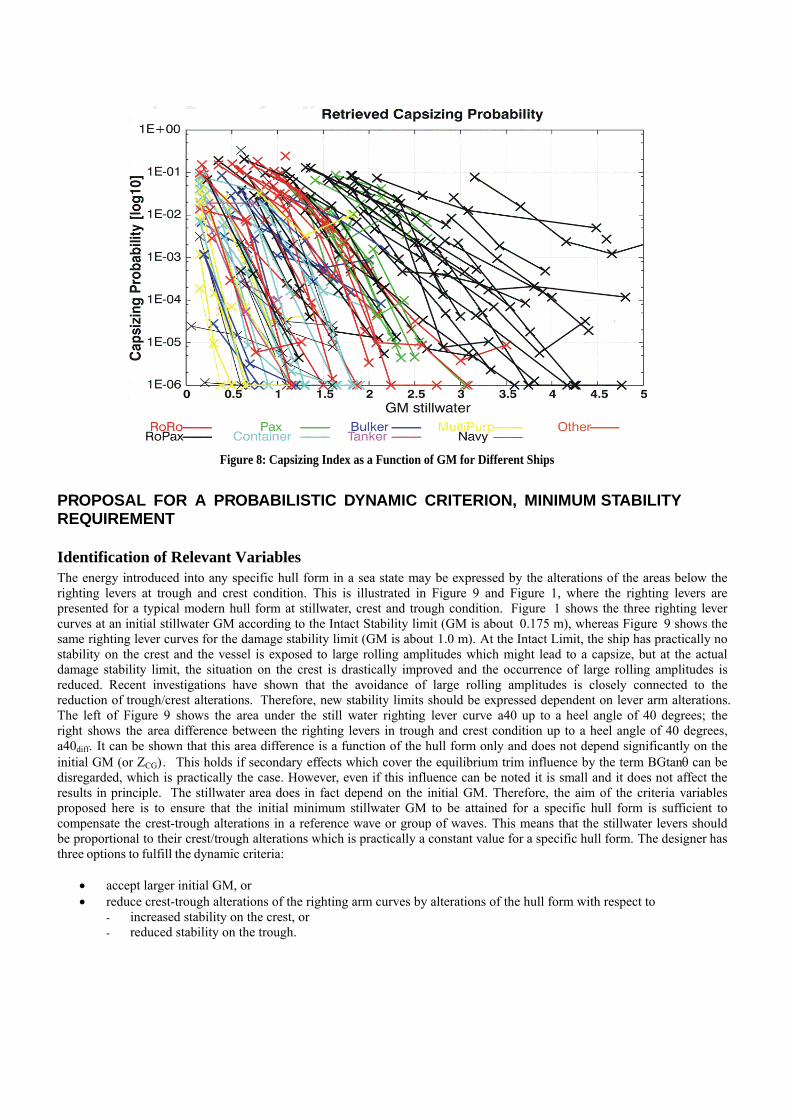
Figure 8: Capsizing Index as a Function of GM for Different Ships
PROPOSAL FOR A PROBABILISTIC DYNAMIC CRITERION, MINIMUM STABILITY REQUIREMENT
Identification of Relevant Variables The energy introduced into any specific hull form in a sea state may be expressed by the alterations of the areas below the righting levers at trough and crest condition. This is illustrated in Figure 9 and Figure 1, where the righting levers are presented for a typical modern hull form at stillwater, crest and trough condition. Figure 1 shows the three righting lever curves at an initial stillwater GM according to the Intact Stability limit (GM is about 0.175 m), whereas Figure 9 shows the same righting lever curves for the damage stability limit (GM is about 1.0 m). At the Intact Limit, the ship has practically no stability on the crest and the vessel is exposed to large rolling amplitudes which might lead to a capsize, but at the actual damage stability limit, the situation on the crest is drastically improved and the occurrence of large rolling amplitudes is reduced. Recent investigations have shown that the avoidance of large rolling amplitudes is closely connected to the reduction of trough/crest alterations. Therefore, new stability limits should be expressed dependent on lever arm alterations. The left of Figure 9 shows the area under the still water righting lever curve a40 up to a heel angle of 40 degrees; the right shows the area difference between the righting levers in trough and crest condition up to a heel angle of 40 degrees, a40diff. It can be shown that this area difference is a function of the hull form only and does not depend significantly on the initial GM (or ZCG). This holds if secondary effects which cover the equilibrium trim influence by the term BGtanθ can be disregarded, which is practically the case. However, even if this influence can be noted it is small and it does not affect the results in principle. The stillwater area does in fact depend on the initial GM. Therefore, the aim of the criteria variables proposed here is to ensure that the initial minimum stillwater GM to be attained for a specific hull form is sufficient to compensate the crest-trough alterations in a reference wave or group of waves. This means that the stillwater levers should be proportional to their crest/trough alterations which is practically a constant value for a specific hull form. The designer has three options to fulfill the dynamic criteria:
• accept larger initial GM, or • reduce crest-trough alterations of the righting arm curves by alterations of the hull form with respect to
- increased stability on the crest, or - reduced stability on the trough.

Figure 9: Areas Below Still water Righting Levers (left) and the Area Difference Trough-Crest (right) -
Same Ship as Figure 1
From both systematical ship design work as well as from many numerical simulations, the following major principles have been found to improve the safety of the ship:
• the safety of the ship was always improved if the alterations between wave crest and trough had been reduced; • most efficient was to improve the stability in the wave crest situation; • as the alterations of the righting levers are a function of the hull form only (secondary effects on trim disregarded),
it was found that some hulls could never go beyond a certain safety limit, whereas other hulls were very safe; • it was found that the limiting GM-values could be smaller if the alterations were smaller, and needed to be larger
for larger alterations; and
• most important parameters seem to be the maximum righting lever at the three conditions described above and the area below the righting lever curve, if all negative areas were included in the calculation.
Figure 10 clearly demonstrates that if the capsizing index is plotted against a variable a15diff/a15, which takes into account the righting lever alterations, the scatter is significantly reduced. This leads to a concept where the stability of the ship should be somehow made dependent of the righting lever alterations between crest and trough condition.
Figure 10: Capsizing Index as a Function of a15 - Alteration for Different Ships
A Probabilistic Intact Stability Concept The dynamic criterion suggested is based on a probabilistic approach, and it has the basis in the simplified determination of a capsizing index which may then be quantitatively judged. The simplified criterion is based on the evaluation of all possible sea states expressed by a significant wave length and wave height, whereas the North Atlantic serves as reference area (e.g. Soeding, Global Seaway Statistics). The simplified capsizing index ak should then be calculated by the formula:
( ) (∑ ∑= =
⋅=3/1 3/1
1 13/13/1,3/13/1, ,,
λ
λλN
i
N
jjijik
H
HaHpa ) [4]

Here, pi,j(λ1/3, H1/3) denotes the probability of occurrence of a sea state given by the significant wave length λ1/3 and height H1/3 and ai,j(λ1/3, H1/3) denotes the probability of capsize of the vessel in this sea state. Based on our previous investigations, the determination of capsizing probability of the vessel is suggested as follows:
jijiji shsa ,,, max401 ⋅−= [5] Here, s40i,j denotes the probability that the ship may survive the sea state i,j expressed by a simple energy criterion, and shmaxi,j denotes the probability that the ship may survive the sea state i,j expressed by the alterations of the maximum righting levers. Survival probabilities s40i,j and shmaxi,j shall be calculated as follows:
( )140/4040 , k
diffaas ji = [6]
In the equation 6, no values for a40/a40diff larger than k1 and no values smaller than 0 can be used.
( )2maxmax/max , k
diffhhsh ji = [7]
Again in equation 7, no values for hmax/hmaxdiff larger than k2 and no values smaller value than 0 can be used. These formulae take into account that if the crest- trough differences are smaller than a limiting minimum value, the ship is regarded as safe. This also holds if these alterations become 0. In the formulas, a40 denotes the still water righting lever area up to 40 degrees, a40diff denotes the difference in the trough-crestrighting levers at the significant wave length λ1/3 and wave height H1/3, hmax denotes the maximum righting lever in range up to 40 degrees, hmaxdiff denotes the trough crest maximum difference of that righting lever for the given wave. k1 and k2 are factors which may be fitted to the results of the direct computations. Based on our comparison to the directly computed capsizing index, the following values are suggested:
k1 = k2 = 0.7 [8] This combination resulted in good agreement of the simplified and directly computed capsizing index and may be taken as a first guess.
THE INFLUENCE OF ROLL DAMPING ON THE CAPSIZING INDEX Besides the righting lever arm changes, the individual roll damping of a vessel has a strong influence on the occurrence of large roll amplitudes. A significant share of the overall roll damping is generated by bilge keels, especially for vessels with low block coefficient. In our numerical simulations, all ships have been analysed taking into account the actual bilge keel height. The question has been put forward whether some allowance in the dynamic criteria proposal could be made if the actual roll damping of a vessel is larger than some standard, which must then be defined. Additional roll damping could result in some allowances for the k-factors in the equations 6 and 7. To clarify this issue, systematic simulations were carried out for a reference vessel which was originally not fitted with bilge keels. As the seakeeping behavior of that vessel was found to be unsatisfactorily, bilge keels were later fitted and the seakeeping behavior was then significantly improved. The capsizing index of the vessel, operated at the intact limit, was determined from the numerical simulations for different bilge keel heights, which were varied between 0. m (no bilge keel at all) and 0.60 m (large roll damping), keeping the length constant at 80.0 m. The results of the calculations are shown in Figure 11.
Figure 11: Capsizing Probability in Dependency of Bilge Keel Height
The results show that the capsizing probability decreases drastically when bilge keels of moderate heights are fitted. In opposite to that, bilge keels larger than commonly used sizes (about 0.37 to 0.43 m) only have very small effect on the capsizing probability. The capsizing index decreases between the 0.15 m bilge keel height and the 0.30 m bilge keel height by about 0.027. The decrease from 0.30 m height to 0.60 m height only adds up to about 0.0048, which is about 17% of the reduction between 0.15 m and 0.30 m bilge keel height. In this particular case, the vessel has been included in our data base with a bilge keel height of 0.37 m as refitted. The example shows that with respect to capsizing safety, it is more useful to ensure at least a minimum damping than to allow a GM reduction which is based on a larger than standard damping. The example clearly shows that the effect on the actual capsizing probability of the larger than “normal” damping is quite small. This is also because the vessel is operated at quite low GM (the minimum intact limit) with relatively low roll velocities. Therefore, it can be concluded that the effect of additional damping from bilge keels (active devices must of course be dealt with differently) larger than standard is negligible for the minimum intact limit. In this context, the existing intact stability rules need to be revised, because additional roll damping by active devices such as FLUME or INTERRING tanks is in fact significantly punished by excessive free surface moment corrections which do additionally not take into account any dynamic effects.
EVALUATION
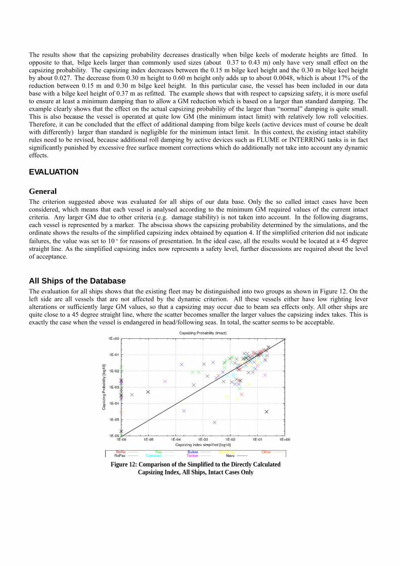
General The criterion suggested above was evaluated for all ships of our data base. Only the so called intact cases have been considered, which means that each vessel is analysed according to the minimum GM required values of the current intact criteria. Any larger GM due to other criteria (e.g. damage stability) is not taken into account. In the following diagrams, each vessel is represented by a marker. The abscissa shows the capsizing probability determined by the simulations, and the ordinate shows the results of the simplified capsizing index obtained by equation 4. If the simplified criterion did not indicate failures, the value was set to 10−6 for reasons of presentation. In the ideal case, all the results would be located at a 45 degree straight line. As the simplified capsizing index now represents a safety level, further discussions are required about the level of acceptance.
All Ships of the Database The evaluation for all ships shows that the existing fleet may be distinguished into two groups as shown in Figure 12. On the left side are all vessels that are not affected by the dynamic criterion. All these vessels either have low righting lever alterations or sufficiently large GM values, so that a capsizing may occur due to beam sea effects only. All other ships are quite close to a 45 degree straight line, where the scatter becomes smaller the larger values the capsizing index takes. This is exactly the case when the vessel is endangered in head/following seas. In total, the scatter seems to be acceptable.
Figure 12: Comparison of the Simplified to the Directly Calculated Capsizing Index, All Ships, Intact Cases Only

Container Vessels Container vessels benefit from their pronounced form stability as shown in Figure 13. Both the directly computed and the simplified capsizing index show that the dominating failure mode is large amplitude roll in head/following seas. The behavior of these vessels is well represented by a 45 degree straight line. Increasing GM leads to a significant increase in safety.
RORO Vessels The trend for RORO vesselslower safety level. The failubecause the ships do not harighting lever alterations. A b
Figure 13: Comparison of the simplified to the directly calculated capsizing index, container vessel, intact cases only
as shown in Figure 14 is generally the same as for container vessels, but on a significantly re mode is the same, but despite the larger GM values, the safety level is drastically smaller ve positive added form stability. The large length/draft ratio makes these vessels vulnerable for etter fit of the data may be achieved by other selections of k1 and k2.
Figure 14: Comparison of the Simplified to the Directly Calculated Capsizing Index, RoRo Vessels, Intact Cases Only

ROPAX Vessels The ROPAX vessels as shown in Figure 15 follow the same trends as identified for container and RORO vessels, but the vessels clearly split into two groups: Vessels located at the left side are all operated at quite large GM values due to design boundary conditions (damage stability and weather criterion). In this group, for example, all Stockholm-conversion cases can be found as can most of the ROPAX vessels with a lower hold. Due to the a.m. reasons, these vessels are not covered by the criterion (beam sea problem). For the other vessels, the same trend as for the RORO vessels can be observed. Active roll damping devices usually fitted to this type of ship were not taken into account in our analysis, which leads to the relatively large capsizing indices.
Figure 15: Comparison of the Simplified to the Directly Calculated Capsizing Index, ROPAX Vessels, Intact Cases Only
Passenger Vessels The same trend as identified for the ROPAX vessels can be found for passenger vessels as shown in Figure 16. Some vessels, namely the smaller ones, are not affected by the criterion because their designs are dictated by beam sea problems. The other ones are located close to a 45 degree straight line at somewhat larger capsizing indices. This may be related to the large rolling moments introduced into these types of ship and, as for the ROPAX vessels, the fact that any active damping devices have not been considered.
Figure 16: Comparison of the Simplified to the Directly Calculated Capsizing Index, Passenger Ships, Intact Cases Only

Bulker, Tanker, and MPV These types of vessels show a small risk of capsize in the head/following sea scenarios as shown in Figure 17. Note that this diagram is scaled differently than the others. As our database consists of many different types of these vessels, also some smaller vessels with insufficient freeboard, the scatter is slightly larger. All the larger vessels of these types are from a practical standpoint not covered by the phenomenon as they are more endangered by beam sea resonances. The same holds true for the smaller vessels, provided they have sufficient freeboard. The scatter in the initial GM values is somewhat larger as for the other ships because different criteria of the existing intact stability code govern the GMreq curve (e.g. max GZ at 25 degrees).
APPLICATION EXAM Four different ships which mThe selection was also donecriterion.
• RORO L • Container L • Bulker L • Gas Tanker L
Two of the vessels selectedlever alterations. One ship dalterations. The Bulker and where problems in followingFor these four ships, the sisystematically varied from according to the Res. 749 is a Figure 18 shows the simplifiactual limiting GM based ostability requirements, whichweather criterion WC, whichoperated below the over allshows the different safety lev
The following conclusions ca
Figure 17: Comparison of the Simplified to the Directly Calculated Capsizing Index, Tankers Bulker and MPVs, Intact Cases Only
PLE
ight be representative for different design philosophies have been selected to test the criterion. with the intention to show which types of ship would definitively not be affected by the a.m.
= 195 m B = 26 m T =7 m = 304 m B = 42.8 m T = 13.00 m
= 146 m B = 23.6 m T = 9.75 m = 300 m B = 50 m T = 12 m
are characterised by large ratios of CWP/CB, which indicates a tendency for large righting oes also have a large length/draft ratio which also results in more pronounced righting lever
the Gas Tanker have been chosen as they represent designs of full block coefficient hull lines, or head seas have seldomly been noted. mplified capsizing index ak was determined by the a. m. procedure, where GM has been 0.15 m to larger values. For all ships, the GM value representing the intact stability limit lso included as well as the actual damage stability limit from the stability booklet.
ed capsizing index plotted against the initial metacentric height. In the diagram, IL denotes the n the application of the 749 criteria, and DL denotes the limiting GM from the damage
may be larger than the intact limit. For the RORO vessel, the intact limit is actually given by the is shown additionally. So it is to be taken into account that none of the vessels analysed can be limiting GM, which is in the DL limit for all four ships investigated. The analysis clearly els of the vessels with respect to intact stability.
n be drawn based on the calculation results:

• Full block coefficient hullforms such as Bulk Carriers or Tankers are not endangered by heavy rolling in longitudinal seas due to the small righting lever alterations between wave trough and wave crest conditions which are typical for these types of ships. Therefore, these ships can be considered as sufficiently safe with respect to the related phenomena in rough weather. This is expressed by the low capsizing probabilities calculated for these types of ships.
• The capsizing probability calculated for the container vessel is in general significantly higher than for the full block ships. This is because container vessels suffer from large righting lever alterations. The related phenomena parametric rolling and pure loss of s tab i l i ty have been mainly observed at container vessels. The graph clearly shows that increasing GM values leads to a significant improvement of the container ship’s safety. However, the analysis for the container vessel also shows that if the container vessel is operated at the DL minimum stability requirement, the safety level is comparable to the level of a full block ship at the intact limit of 15 cm. This means in practice that the damage stability limit shifts the capsizing limit to comparable values as for full block ships at the intact limit.
• The lowest safety level is observed for the RORO vessels. Ships of this type often suffer from extremely high
lever arm alterations and, thus, are critically endangered by the a. m. phenomena. The limiting GM values for the Intact Stability Criteria as well as for the IMO Weather Criterion result in very high capsizing probabilities. Seen from an intact stability point of view, the weather criterion is the only intact criterion that provides some safety for this specific ship type. But as for the container ship, the damage stability calculation results in a higher limiting GM and, thus, indirectly increases the intact stability level in practice. Nevertheless, even this higher GM results in capsizing probabilities which are still significantly larger than those of the Bulk Carrier and the Gas Tanker. The safety level is roughly the same as for the container ship at the Intact Limit.
Figure 18: Capsizing Probability versus GM for the Different Ships Investigated

REFERENCES
BILLERBEK, H. (2005) “SinSee - Beurteilung der Schiffssicherheit in schwerem Seegang,” BMBF- Statusseminar 2005,
Rostock. BLUME, P. (1979) “Experimentelle Bestimmung von Koeffizienten der wirksamen Rolldaempfung und ihre Anwendung zur
Abschaetzung extremer Rollwinkel,” Schiffstechnik Band 26. BLUME, P. (1987) “Development of New Stability Criteria for Modern Dry Cargo Vessels,” Proceedings of PRADS 1987. CRAMER, H. and KRUEGER, S. (2001) “Numerical capsizing simulations and consequences for ship design,” JSTG
2001, Springer.
CRAMER, H., KRUEGER, S. and HINRICHS, R. (2001) “Towards dynamic stability criteria for the evaluation of intact
stability problems,” Proceedings of PRADS 2004, Travemuende. HASS, C. (2001) “Darstellung des Stabilitaetsverhaltens von Schiffen verschiedener Typen und Groesse mittels statischer
Berechnung und Simulation,” Diploma Thesis, TU Hamburg- Harburg, in preparation. KROEGER, P. (1987) “Simulation der Rollbewegung von Schiffen im Seegang,” Bericht Nr. 473, Institut fuer Schiffbau der
Universitaet Hamburg.
KRUEGER, S.: (1998) “Performance Based Stability,” DCAMM 2002, Lyngby.
PETEY, F. (1988) “Abschlussbericht zur Erweiterung des Vorhabens Leckstabilitaet im Seegang,” Institut fuer Schiffbau der
Universitaet Hamburg. SOEDING, H. (1987) “Ermittlung der Kentergefahr aus Bewegungssimulationen,” Schiffstechnik Band 34
SOEDING, H. (1988) “Berechnung der Bewegungen und Belastungen von SWATH-Schiffen und Katamaranen im Seegang,”
Bericht Nr. 483, Institut fuer Schiffbau der Universitaet Hamburg. SOEDING, H. (2001) Global Seaway Statistics Report Nr. 610, TU Hamburg-Harburg, Schriftenreihe Schiffbau.