development of energy models for design space exploration
TRANSCRIPT

Development of Energy Models for Design Space Exploration ofEmbedded Many-Core Systems
Christian Klarhorst†, Martin Flasskamp†, Johannes Ax†,
Thorsten Jungeblut†, Wayne Kelly*, Mario Porrmann†, and Ulrich Rückert†
† Cognitronics and Sensor Systems Group, * Science and Engineering FacultyCITEC, Bielefeld University, Queensland University of Technology
Bielefeld, Germany Brisbane, Australia
ABSTRACTThis paper introduces a methodology to develop energy models forthe design space exploration of embedded many-core systems. Thedesign process of such systems can benefit from sophisticated mod-els. Software and hardware can be specifically optimized based oncomprehensive knowledge about application scenario and hardwarebehavior. The contribution of our work is an automated frameworkto estimate the energy consumption at an arbitrary abstractionlevel without the need to provide further information about the sys-tem. We validated our framework with the configurable many-coresystem CoreVA-MPSoC. Compared to a simulation of the CoreVA-MPSoC on gate level in a 28 nm FD-SOI standard cell technology,our framework shows an average estimation error of about 4 %.
KEYWORDSenergy modeling, many-core architecture, design space exploration
1 INTRODUCTIONEmbedded system designers often have to deal with trade-offs. Oneis to optimize a system that performs acceptable in the generalcase instead of building an application-specific system. A generalpurpose CPU excels an ASIC in flexibility but underlies it in perfor-mance. However, a high configurability of hardware and softwareincreases the available design space tremendously.
An embedded system passes through many different designstages, involving different groups of developers from the hardware,software and system design domain. All have their own perspec-tive on the system at different abstraction levels. For instance asoftware developer does not know in detail how the usage of dif-ferent hardware components affects the performance or energyconsumption of an application. Just as a hardware developer maynot have enough information about specific application require-ments in an early design stage. Each group relies on estimationsof specific system metrics that are gathered by tools to performdesign decisions. Building optimized designs for specific use casesoften requires an information flow between all involved groups inorder to find solutions that are holistically optimal, which leads to
HIP3ES’18, January 2018, Manchester, United Kingdom2018. ACM ISBN 978-x-xxxx-xxxx-x/YY/MM. . . $15.00https://doi.org/10.1145/nnnnnnn.nnnnnnn
a hardware software co-developing process. Therefore, it is appro-priate to postpone trade-off decisions during the design processin order to decide at the right time, as informed as possible andfor the right use case scenario. However, keeping more degrees offreedom lead to a growing design space on all different abstractionlevels and the available and explored space better has to be handledautomatically.
Our target platform is the embeddedMPSoC architecture CoreVA-MPSoC, which is highly configurable at design time. The CoreVA-MPSoC toolchain has the objective to create an interface betweenthe different developer groups. It consists of an MPSoC systemspecification in XML, parameterized VHDL SoC components, agraphical user interface to configure MPSoCs, a cycle accurate sys-tem simulator, a software backend based on the LLVM compilerframework and our CoreVA-MPSoC compiler together with a broadrange of single and many-core applications. The VHDL SoC com-ponents are bundled with their API specification into a componentlibrary. The interaction between these components is depicted inFigure 1.
The system needs to be accurately modeled during the designprocess of hardware and software despite of the high configurability.This can be achieved by combining partial models of individualcomponents like execution units or memories to a complete systemmodel. There are many different metrics to evaluate the systemdepending on the specific abstraction level. In [5] we presented a
MPSoC Compiler
MPSoC GUI
LLVM
MPSoC SolutionSW + HW + Estimation
Prototype
ASICSimulator
Synth Tools
FPGA
MPSoCSpecification
Application Component LibraryAPI VHDL
Figure 1: Interaction of CoreVA-MPSoC toolchain compo-nents
arX
iv:1
801.
0424
2v2
[cs
.DC
] 1
5 Ja
n 20
18
HIP3ES’18, January 2018, Manchester, United Kingdom C. Klarhorst et al.
model to estimate the throughput of an MPSoC. In this work wefocus on modeling the energy consumption and how these modelsinfluence the whole MPSoC design process. Energy efficiency is acrucial design aspect for all kinds of processor systems. Obviously,battery powered embedded systems are limited regarding their runtime. Additionally, the power consumption of high performancesystems limits their performance due to heat dissipation. The powerconsumption can be addressed at all design stages. On the hardwaredevelopment side by choosing or dimensioning components and onthe software side by energy-aware compiler optimization. Hence,we introduce an energy estimation framework for the CoreVA-MPSoC toolchain.
Current research typically focuses on modeling effects like cachebehavior [11] or components like NoC routers [23] of a specificsystem. In contrast, we want to cover a broad range of systems as forinstance the CoreVA-MPSoC as a highly configurable architecture.A huge design space implies to trade off the required accuracyagainst the setup time of the model. Therefore, our frameworkgeneralizes the model definition and automates its creation. It isable to create an energy model based on the needs of different usergroups that variate in granularity, accuracy and available time.
This work is organized as follows. The hardware and softwareparts of the CoreVA-MPSoC project are introduced in Sections 2.1and 2.2. An overview of related work in the domain of modelingand estimating energy consumption is presented in Section 3. Sec-tion 4 describes how energy estimation correlates with systemstate transitions and Section 5 goes into details how the model cre-ation is automatically done by our energy estimation framework.The analysis of our energy estimation framework is presented inSection 6.
2 THE COREVA-MPSOC PROJECTAs a target platform for our estimation framework presented in thiswork, we use the self-developed many-core system CoreVA-MPSoC.The CoreVA-MPSoC is used for application domains like signalprocessing, vision processing, and encryption in embedded andenergy-limited systems. In [19] the CoreVA-MPSoC is presented asa platform for Software-Defined-Radio applications.
2.1 Hardware ArchitectureThe CoreVA-MPSoC can be classified into the domain of many-core architectures. Many-core architectures are defined by a very
...
CPU ClusterNI
CPU NCPU 1CPU 0
Bus Interconnect
Instr.
Me
m
CPU
Cluster
CPU
Cluster
CPU
Cluster
CPU
Cluster
Data
Me
m
Instr.
Me
m
Data
Me
m
Instr.
Me
m
Data
Me
m
Shared L1 Data Mem.
CPU
Cluster
CPU
Cluster
CPU
Cluster
CPU
Cluster
CPU
Cluster
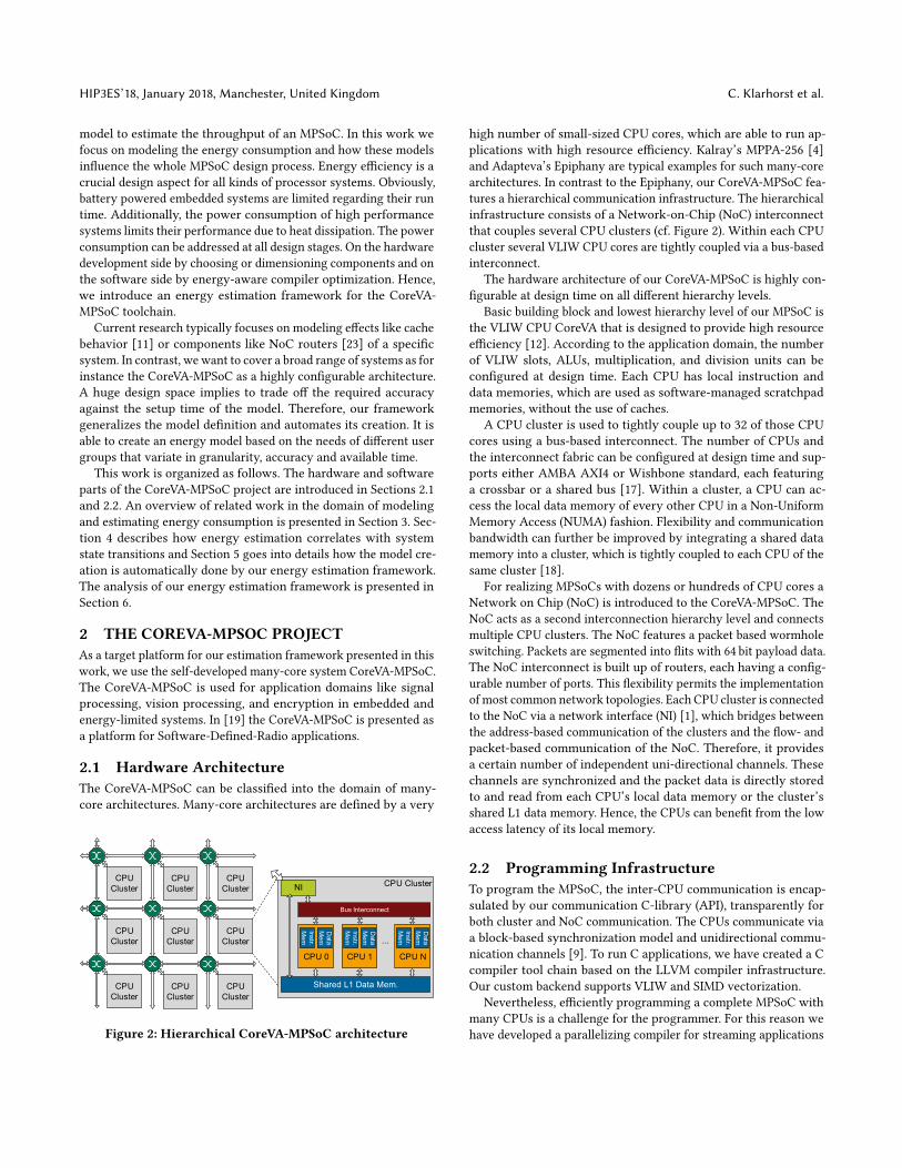
Figure 2: Hierarchical CoreVA-MPSoC architecture
high number of small-sized CPU cores, which are able to run ap-plications with high resource efficiency. Kalray’s MPPA-256 [4]and Adapteva’s Epiphany are typical examples for such many-corearchitectures. In contrast to the Epiphany, our CoreVA-MPSoC fea-tures a hierarchical communication infrastructure. The hierarchicalinfrastructure consists of a Network-on-Chip (NoC) interconnectthat couples several CPU clusters (cf. Figure 2). Within each CPUcluster several VLIW CPU cores are tightly coupled via a bus-basedinterconnect.
The hardware architecture of our CoreVA-MPSoC is highly con-figurable at design time on all different hierarchy levels.
Basic building block and lowest hierarchy level of our MPSoC isthe VLIW CPU CoreVA that is designed to provide high resourceefficiency [12]. According to the application domain, the numberof VLIW slots, ALUs, multiplication, and division units can beconfigured at design time. Each CPU has local instruction anddata memories, which are used as software-managed scratchpadmemories, without the use of caches.
A CPU cluster is used to tightly couple up to 32 of those CPUcores using a bus-based interconnect. The number of CPUs andthe interconnect fabric can be configured at design time and sup-ports either AMBA AXI4 or Wishbone standard, each featuringa crossbar or a shared bus [17]. Within a cluster, a CPU can ac-cess the local data memory of every other CPU in a Non-UniformMemory Access (NUMA) fashion. Flexibility and communicationbandwidth can further be improved by integrating a shared datamemory into a cluster, which is tightly coupled to each CPU of thesame cluster [18].
For realizing MPSoCs with dozens or hundreds of CPU cores aNetwork on Chip (NoC) is introduced to the CoreVA-MPSoC. TheNoC acts as a second interconnection hierarchy level and connectsmultiple CPU clusters. The NoC features a packet based wormholeswitching. Packets are segmented into flits with 64 bit payload data.The NoC interconnect is built up of routers, each having a config-urable number of ports. This flexibility permits the implementationof most common network topologies. Each CPU cluster is connectedto the NoC via a network interface (NI) [1], which bridges betweenthe address-based communication of the clusters and the flow- andpacket-based communication of the NoC. Therefore, it providesa certain number of independent uni-directional channels. Thesechannels are synchronized and the packet data is directly storedto and read from each CPU’s local data memory or the cluster’sshared L1 data memory. Hence, the CPUs can benefit from the lowaccess latency of its local memory.
2.2 Programming InfrastructureTo program the MPSoC, the inter-CPU communication is encap-sulated by our communication C-library (API), transparently forboth cluster and NoC communication. The CPUs communicate viaa block-based synchronization model and unidirectional commu-nication channels [9]. To run C applications, we have created a Ccompiler tool chain based on the LLVM compiler infrastructure.Our custom backend supports VLIW and SIMD vectorization.
Nevertheless, efficiently programming a complete MPSoC withmany CPUs is a challenge for the programmer. For this reason wehave developed a parallelizing compiler for streaming applications

Development of Energy Models for Design Space Exploration HIP3ES’18, January 2018, Manchester, United Kingdom
to assist in programming the CoreVA-MPSoC [5, 9]. This compiler,called CoreVA-MPSoC compiler, processes applications written inthe StreamIt language [20]. An application is represented by a struc-tured data flow graph, which describes the inherent parallelism ofits tasks. Our compiler for streaming applications searches for avalid partition with the best performance. It utilizes an approachbased on simulated annealing to map the tasks of a program ontothe individual CPUs of the MPSoC. A typical optimization goal isto find a placement for the application’s tasks which maximizes thethroughput or minimizes the latency of an application. During thepartitioning process the compiler exploits three degrees of freedomto alter an application’s data flow graph. Firstly, the compiler de-cides on which processor a task is placed. Secondly, a task can becloned to exploit data parallelism. Thirdly, the granularity of workdone in each iteration can be increased to reduce the overhead ofcommunication. These changes are called mutations and furtherincrease the search space for the partitioning algorithm.
Every partition is judged regarding the achieved performance,by a Simulation Based Estimation (SBE) model, which combinesa single execution-based simulation and an analytic approach [5].MPSoC configurations with the same number of CPUs can differin many ways like topology, communication infrastructure andmemory architecture. All these characteristics are modeled in ourSBE to achieve accurate performance estimations. In addition, apartition is also checked if any hardware limits of a specifiedMPSoCconfiguration are exceeded. Therefore, our SBE model estimatesthe consumption of data memory and enables the partitioningalgorithm to reject partitions exceeding the physically availablememory.
Finally, the best partition is used to generate an individual Ccode file for each CPU of the MPSoC. With the energy estimationframework presented in this paper, our SBE model can be extendedto estimate the expected energy consumption of an application andperform energy-aware compilers optimization.
3 RELATEDWORKEnergy consumption is still a research topic of much interest. Onthe one hand power consumption imposes limits on the systemperformance due to e.g. heat dissipation. On the other hand powerefficiency often limits the diversity of target applications. Researchfocuses on energy models, simulators and configuration space ex-ploration, often to characterize various system aspects. Differencesare in the purpose, target user group, level of detail and the methodto infer and analyze those models. The purpose might be mainlydriven by the needs of the various development process levels toprovide benefits for the involved user groups. Research was oftenused to limit the design-space and point out design inefficienciesas early as possible [21].
In the area of hardware development research focuses on dif-ferent levels of detail. On gate level Roselló et al. [16] present anenergy model for domino CMOS gates based on a detailed descrip-tion of internal capacitance switching and discharging currents.Many models target specific processor components for exampleDramsim [15] and Cacti [22] are well-known tools used for timingand energy analysis of DRAMS and caches. In [23]Wolkotte et al. fo-cus on NoC routers while the Orion2 [8] network simulator models
complete Network on Chips. Energy simulation tools for differentkinds of processors are provided by the frameworks Watch [3] forCPUs and GPUWatch [10] for GPUs. Just as by the work of Vasilakiset al. [21] for ARM processors and Jordans et al. [7] for VLIW proces-sors. An instruction-level energy characterization of the AdaptevaEpiphany SoC was done by Ortiz et al. in [13]. They measuredthe energy consumption of the SoC with a digital current meterwhile executing a number of microbenchmarks. The McPat frame-work [11] focuses on complete SoCs by describing fundamentalcomponents of multi-core and many-core processor configurationsin a flexible XML interface. Specific properties and implementationdetails like cache behavior and timing are described quantitatively.By evaluating the model McPat estimates power, area and timing.Hesse et al. created a power consumption model of a completecircuit board of a wireless sensor node [6]. The model containingsensor, microcontroller, wireless transceiver and power supply isutilized for choosing components at an early design stage. In thecompiler research area the configuration space of compiler optionsand its impact on power consumption was explored by Pallisteret al. [14]. They performed power measurements on five embeddedplatforms to ensure all architectural effects are captured. All usergroups focus on different levels of detail or granularity and admitdifferent error margins.
Besides the target platform or components the aforementionedwork further differs in theirmethodology. TheMcPat framework [11]estimates energy based on a model specification while other workgathers data from various sources to fit models like Ortiz et al.did by measuring the MPSoC [13]. Multiple options to create andgather data for the second option may be found in research. Mi-crobenchmarks which are often handwritten are used for the be-havior creation in contrast to real applications or benchmark suits.Furthermore data can be gathered by simulating those systems orby measuring final ASICs under real world conditions. The simula-tion method provides fine granular power analysis, e.g. it is possibleto gather power data for all components of a CPU using gate levelanalysis at the cost of an often compute intensive but scalable simu-lation Finally, the simulation method is able to provide data beforetape out and it is able to simulate various environment conditions.While the measurement method provides better accuracy becauseit incorporates all physical effects and uses real word conditions.
IS-Simulator EnergyEstimation
Model
ConstantsFunction
GatelevelSimulation
Application
HardwareSpecification
Figure 3: Exemplary energy estimation of instruction setsimulation by model created at gate level

HIP3ES’18, January 2018, Manchester, United Kingdom C. Klarhorst et al.
4 ENERGY ESTIMATION METHODOLOGIESEnergy consumption of digital circuits originates from differentphysical effects. The static power consumption is the result of leak-age current of the transistors. While the dynamic power consump-tion is composed of switching current, a transistor switches fromone logic state to another, and the switching frequency dependentload of charging external load capacitance. The state of the entiresystem can be described by the states of all components.
Our idea is to describe the system state and correlate energy con-sumption with the system state transitions. This also gives us theability to correlate energy consumption from a lower abstractionlevel with high-level state transitions. Figure 3 shows exemplaryhow the result of gate level simulations can be utilized to developan energy model on logic level. This model can be used togetherwith a cycle accurate system simulator to estimate the energy con-sumption.
Model Constants and FunctionsThe state of a system can be described at all abstraction levels. Anoverview of abstraction levels shows Table 1. On circuit level thesystem state is described by differential equations of the transistors.Similarly, instructions define the system state at the higher cycleabstraction level. Without additional information we could nowperform energy measurements and correlate them with state transi-tions. A comprehensive model containing all possible state transfor-mations could be created by performing nmeas = nstates ×nstatesmeasurements. But unfortunately an incalculable amount of waysto describe the system state exist.
This correlation is visualized in Figure 4 on the basis of theCoreVA-MPSoC. Figure 4 (a) show a sparse model which only dis-tinguishes whether a component was used (coloured) or unused(grey) during the period of measurement. In contrast the model in(c) breaks down the state of each component to a very fine-grainedstate description, visualized by multicolored bar charts on the CPUcomponents and pie charts on the NoC routers. For instance thismodel considers the variation of power consumption for differentCPU instructions. A trade-off between both attempts depicts model(b), which considers the time a used components was in active oridle state. In this case the state description of a component containsno redundant states.
On cycle level system state transitions might be caused by asequence of instructions as a result of an execution of a function.The energy consumption per instruction forms the model constantson cycle level (cf. Figure 3). Setting up the model includes thecreation of system behavior, the capturing of the system’s energy
Table 1: Abstraction levels
Abstraction Level System State GranularityCircuit Transistors Differential EquationsLogic Gates Boolean FunctionsRTL Registers RTL Spec.Cycle Instructions InstructionTask Functions System Spec.Application Program Application Spec.
consumption during simulation and the final model determination.Accordingly, the setup time for a simple CPU core model wouldinclude the generation of micro benchmarks, gate level simulationsand fitting the model constants.
On each abstraction level the system state is modeled with adifferent granularity. Therefore, we added a function to the modelto transform the state description from simulation into the statedescription used by the model. It is able to add, change and removestate information and provides the necessary flexibility while itmay also include additional system assumptions to simplify e.g.reduce the system description. This reduction results in faster modelevaluation and setup time. The same model constants can be reusedon different abstraction levels by transforming the system statewith different model functions.
The model is evaluated by executing the model function andcombining the resulting state with the model parameters. Since nosimulation is required the model evaluation is only a fast computa-tion.
Exemplary MPSoC Component ModelsAs an example the following paragraph describes the creation of anmodel for an ideal NoC communication. The NoC of the CoreVA-MPSoC is organized as a 2D-mesh, described in Section 2.1. Atransmission can be characterized by the coordinates of the involvedCPUs and the size of the transmitted buffer. So a naive model wouldcontain all possible permutations of the coordinates and all possiblepacket sizes resulting in a huge model.
The path on which a packet passes through the NoC can becharacterized by a sequence of independent hops (routers). Thatway, the foregoing model can be drastically reduced by removingthe redundancy of individual links. The reduced model would thencontain all number of hops and possible packet sizes together witha function to define the new distance metric number of hops, forexample by nhops = manhattan_dist(x ,y).
More knowledge about the hardware could be incorporated intothe model to reduce it even further. For example, one could assume
System State Description FullSparse
Redundancy No GainLoss of Accuracy
(a) (b) (c)
Figure 4: Abstraction levels of system state description perperiod of measurement
Development of Energy Models for Design Space Exploration HIP3ES’18, January 2018, Manchester, United Kingdom
that the energy consumption will increase linearly with the packetsize (under the assumption of no congestion). A model containingall available number of hops together with two constants for thelinear functions would be reduced again but possibly at the expenseof an increasing estimation error. More detailed results and furtheranalysis follow in Section 6.
5 ENERGY MODELING FRAMEWORKThe contribution of our work is a framework to estimate the energyconsumption at an arbitrary abstraction level without the needto provide further information about the system. However, theframework allows for adding additional knowledge to the systemto improve estimation accuracy or to accelerate the model setuptime.
Back annotated simulations on gate level could be employed tocreate a model, as long as one is in possession of the RTL (VHDL,Verilog) sources of the system and a process design kit or corre-sponding IP-Cores. Afterwards the simulation results can be an-alyzed by commercial tools like Cadence© Voltus™ to obtain anenergy estimation. Unfortunately, comprehensive gate level simu-lations for a complex system like the configurable CoreVA-MPSoCarchitecture would imply a large number of simulations. Accord-ingly, these require a lot of simulation time and resources as wellas tool licenses. Therefore, our framework enables the developerto obtain an energy estimation faster and with an acceptable lossof accuracy with the help of reducing the number of necessarysimulations by including system knowledge into the model.
We require a set of system states and energy information to findthe correlation parameters for the specific energy model. The sys-tem states (the system behavior) are created by a previously selectedapplication or bymicrobenchmarks and a gate level simulation. Thissimulation provides the necessary state information together withthe occurred switching activity data that is fed into the tools forenergy measurement. We further provide a trace infrastructure,implemented up to the C level, in order to provide a method tocreate additional, high level system state information that could beused in the model or by the model function. We developed a tool toautomatically create a broad range of microbenchmarks based onuser preferences and on the available information in the toolchain.The tool is able to variate the use pattern of all SoC componentsthat have a specified API description. This includes for exampleall different communication and memory components. It is furtherable to create microbenchmarks for the CoreVA CPU cores. Thisis done automatically by parsing the instruction set description al-ready available in the software toolchain. The tool always generatessetup code in front of every test case in order to bring the CoreVAinto a defined state to have a reproductive measuring environment.
6 VALIDATIONThere are many effects in a System on Chip that have an impacton the energy consumption. This work focuses on a many-coresystem with a 2D-mesh NoC which connects multiple clusters eachcontaining four fully connected CoreVA CPUs. The CoreVA CPUcores include two VLIW slots with one load/store and multiplica-tion/division unit. Each CPU is configured with 16 kB of instructionmemory organized in two banks and 16 kB of local data memory
equally organized. Each cluster additionally contains 64 kByte ofshared data memory, tightly coupled to each CPU and organized ineight banks. Each memory bank in the system contains 2 k wordswith 32 bit word-size. Each network interface (NI) supports 128synchronous channels with an effective bandwidth of 64 bit perclock cycle (cf. Section 2.1). The cluster interconnects are carriedout as crossbars with a width of 64 bit.
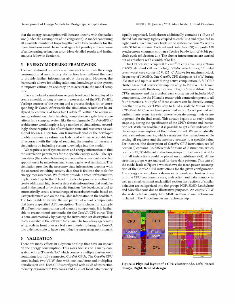
One CPU cluster occupies 0.817mm2 of chip area using a 28 nmFD-SOI standard cell technology: STMicroelectronics, 10 metallayer, worst case corner 1.0 V, 125 ◦C. Allows for maximum clockfrequency of 700MHz. One CoreVA CPU dissipates 4.5mW duringidle state and up to 30mW during active computation. A full CPUcluster has a total power consumption of up to 150mW. The layoutcorresponds with the design shown in Figure 5. In addition to theCPUs, memory and the crossbar, each cluster layout includes NoCcomponents, like the NI and a router with connection ports to allfour directions. Multiple of these clusters can be directly strungtogether on a top level P&R step to build a scalable MPSoC witha 2D-Mesh NoC, as we have presented in [2]. As we pointed outearlier, many scenarios exist where accurate energy metrics areimportant for the final result. This already begins in an early designstage, e.g. during the specification of the CPU’s feature and instruc-tion set. With our toolchain it is possible to get a fast indicator forthe energy consumption of the instruction set. We automaticallycreate microbenchmarks, which variate just the instructions whilesetting all registers and the memory content to a specific value.For instance, the description of CoreVA CPU instruction set (cf.Section 5) contains 155 different definitions of instructions, whichresults in 20,093 different instruction groups for the two VLIW slots(not all instructions could be placed on an arbitrary slot). All in-struction groups were analyzed for three data patterns. This part ofthe model leads to Figure 6 which shows the mean power consump-tion of the CoreVA CPU instructions for the given configuration.The energy consumption is shown in pico joule and broken downinto the CPU components core, instruction and data memory aswell as a small constant unclassified section. Instructions of similarbehavior are categorized into the groups NOP, SIMD, Load/Storeand Miscellaneous due to illustrative purposes. An empty VLIWslot is depicted as Empty. Non SIMD arithmetic instructions areincluded in the Miscellaneous instruction group.
Shared
Mem.
Shared
Mem.
CPU CPU
CPUCPU
Bus
NI
RouterNI-Mem.
Po
rt 3
Port 4
Port 2
Po
rt 1
Figure 5: Physical layout of a CPU cluster node. Left: Placeddesign, Right: Routed design

HIP3ES’18, January 2018, Manchester, United Kingdom C. Klarhorst et al.
As one might expect, the NOP instruction leads to the lowestenergy consumption of the CPU core. Whereas the most energy isconsumed when a SIMD instruction is executed due to the highestcore activity. The data memory shown in blue has obviously animpact only on the power consumption of Load/Store instructions.The worst case difference between the three data patterns men-tioned above is 2.6mW. The energy consumption of the instructionmemory depends on the VLIW instruction format. A VLIW instruc-tion for a CoreVA CPU with two slots may contain instructions forboth or only one slot. The latter case results in instruction com-pression to save space in memory and energy on access as seen inFigure 6. The provided hardware macro of a single CoreVA CPU hasa minimum power usage of 15.3mW and a maximum of 38.0mW.The model creation needs 55 h of gate level simulation and 70 daysof power analysis time to run 60,279 different tests on a single In-tel® Xeon® E5-1650 v4 CPU core. Actually, the tests are distributedonto 26 CPU cores in parallel.
Many detailed effects on the power consumption were left aside,like the position of the instruction or the data dependency. There-fore, we investigated how the specific instruction memory addresseffects the energy consumption of the instruction memory. Wecreate microbenchmarks where the position of the instruction isvariated while the rest of the system state remains constant. An16 kb instruction memory is able to store 2048 2-Slot and up to4096 1-Slot CoreVA instructions because of instruction compres-sion. The energy consumption for the first 800 instruction memoryaddresses is shown in Figure 7. All addresses were filled with thesame instruction hence the energy consumption only depends onthe accessed address and is not a function on the memory content.The position creates an energy consumption range of 1.7 pJ for twoVLIW slot instructions and 3.2 pJ for a single slot, which can beexplained by the internal interconnect of the memory blocks. Weassume that the arrangement of the data points is caused by thetree like structure of the memory address decoder.
Nop
-Em
pty
Mis
c-E
mpt
y
SIM
D-E
mpt
y
Nop
-Nop
Nop
-Mis
c
Mis
c-N
op
Nop
-SIM
D
Mis
c-M
isc
SIM
D-N
op
Mis
c-S
IMD
Ld/S
t-Em
pty
Ld/S
t-Nop
Ld/S
t-Mis
c
Ld/S
t-SIM
D
CoreVA Instruction Group
0
10
20
30
40
50
60
Ave
rage
Ene
rgy
Con
sum
ptio
n in
pJ
UnclassifiedCore
Instruction MemoryData Memory
Figure 6: Average power consumption of CoreVA CPU in-struction groups for two VLIW slots divided into CPU com-ponents
A communication transfer between two CPU cores across theNoC involves the two CPU cores itself, routers, the interfaces be-tween CPU cluster and NoC (NI) and other communication in-frastructure like the bus interconnect within a CPU cluster. Ourtoolchain is able to generate benchmarks with the tool presentedin Section 5 to analyze communication characteristics in an auto-mated way based on an API description. Therefore, it is possible tovariate the packet size for a NoC communication between two coreson different clusters. Figure 8 shows the energy consumption ofspecific transfer sizes. The packet size variates from 4 to 1024 bytein 4 byte increments. The zoomed view includes 36 data points from374 to 446 in 2 byte increments. Due to the 64 bit flit size, into whichall NoC packets are segmented (cf. Section 2.1), the plot shows astaircase function. One bar depicts the energy consumption in nJand is separated into the shares of the involved components. CPUsynchronization, data memories, bus, router and the NoC interfaceare shown in red, blue, green, bright red and gray. The unclassifiedpart shown in yellow contains, among others, especially the partsof the CPU cluster interconnect, which are not assigned to thebus part. The costs for CPU synchronization are software costs tosynchronize the communication channel. More details about thesesoftware costs for communication are presented in [1].
Generating the results of 256 data points for the plot of Figure 8took 40 h of simulation time and 170 h for power analysis. The datawas further approximated with a linear and a staircase function asshown in Section 4. We used 16 data points around the center forthe fit in order to reduce the simulation time to 3 h and the poweranalysis time to 11 h. The linear function shown as a blue line hada maximum error of 62 pJ while the staircase function shown as agreen line had a maximum error of 52 pJ.
We validated the applicability of our approach by estimatingthe energy consumption for a set of five many-core benchmarksfrom the StreamIt benchmark suite [20]. The analyzed benchmarksare chosen from the signal processing, matrix multiplication andsorting algorithm domain. Compared to a gate level simulation theaverage estimation error is about 4%with amaximum absolute error
21.0
21.5
22.0
22.5
23.0Nop - Nop Nop - None
0 100 200 300 400 500 600 700 800Instruction Memory Address
9.09.5
10.010.511.011.512.012.513.0
Ener
gy C
onsu
mpt
ion
in p
J
Figure 7: Spatial correlation between energy consumptionof nop instruction and address in instruction memory

Development of Energy Models for Design Space Exploration HIP3ES’18, January 2018, Manchester, United Kingdom
4 128 256 384 512 640 768 896 1024Packet Size in byte
5
6
7
8
9
10
Ener
gy C
onsu
mpt
ion
in n
J
CPU SynchronizationData MemoriesUnclassified
BusRouterNI
Zoom: 8x
Figure 8: Energy consumption in nJ of NoC transmissionswith varying packet size separated into components
of 10% for a simplified model. The model considers all instructiontypes and three data pattern but not the instruction position in thememory. However, the accuracy depends on how many effects aretaken into account when establishing the model.
7 CONCLUSIONThis paper presents an approach to develop and use energy modelsfor a design space exploration of embedded many-core systems.The contribution of our work is a framework to estimate the energyconsumption at an arbitrary abstraction level without the needto provide further information about the system. Therefore, wedeveloped an automatic tool flow to fill the energy model withenergy information gathered from gate level simulations of basicsystem states of different components of a many-core system. Oncethe energy model is filled, it can be used on higher abstraction levelsto get fast and accurate energy estimations for specific applicationsand hardware configurations of the many-core system.
To validate our framework, we used our, at design time, highlyconfigurable many-core system CoreVA-MPSoC as a target archi-tecture. Compared to a gate level simulation of the CoreVA-MPSoCin a 28 nm FD-SOI standard cell technology, the average estima-tion error of our energy model framework is about 4 %. Comparedto other approaches, like Ortiz et al. [13], we are able to analyzethe energy consumption more fine-grained without the restrictionto measure an existing ASIC. Hence, our model contains internalMPSoC components like instruction memory and VLIW slots aswell. However, Ortiz et al. achieve a more accurate total energyestimation at instruction level. The design process of highly con-figurable embedded systems like the CoreVA-MPSoC benefits fromsuch a sophisticated model. Applications may be specifically opti-mized for tailored systems by modeling the different variants andcharacteristics of system components. A trade-off can be foundbased on comprehensive knowledge about application scenarioand hardware behavior. In future work, our MPSoC compiler will
use the presented energy model to automatically map streamingapplications to our CoreVA-MPSoC, optimized for energy.
ACKNOWLEDGMENTThe reported research was supported through project grants Kogni-Home (German Federal Ministry of Education and Research (BMBF)Grant No. 16SV7054K), the Cluster of Excellence Cognitive Inter-action Technology "CITEC" (EXC 277) at Bielefeld University andthe BMBF Leading-Edge Cluster "Intelligent Technical SystemsOstWestfalenLippe" (it’s OWL).
REFERENCES[1] Johannes Ax et al. 2015. In press. System-Level Analysis of Network Interfaces for
Hierarchical MPSoCs. In NoCArc. ACM. https://doi.org/10.1145/2835512.2835513[2] Johannes Ax et al. 2017. Comparing synchronous, mesochronous and asynchro-
nous NoCs for GALS based MPSoC. In MCSoC ’17.[3] D. Brooks, V. Tiwari, and M. Martonosi. 2000. Wattch: a framework for
architectural-level power analysis and optimizations. In Proceedings of 27th Inter-national Symposium on Computer Architecture (IEEE Cat. No.RS00201).
[4] Benoit Dupont de Dinechin et al. 2013. A clustered manycore processorarchitecture for embedded and accelerated applications. In HPEC ’13. IEEE.https://doi.org/10.1109/HPEC.2013.6670342
[5] Martin Flasskamp et al. 2016. Performance estimation of streaming applicationsfor hierarchical MPSoCs. In RAPIDO ’16, Vol. 18-January. ACM Press. https://doi.org/10.1145/2852339.2852342
[6] Marc Hesse, Michael Adams, Timm Hormann, and Ulrich Rückert. 2016. Towardsa comprehensive power consumption model for wireless sensor nodes. In BSN’16. https://doi.org/10.1109/BSN.2016.7516293
[7] R. Jordans, R. Corvino, L. Józwiak, and H. Corporaal. 2013. An Efficient Methodfor Energy Estimation of Application Specific Instruction-Set Processors. InEuromicro DSD ’13. https://doi.org/10.1109/DSD.2013.120
[8] A. B. Kahng, Bin Li, L. S. Peh, and K. Samadi. 2009. ORION 2.0: A fast and accurateNoC power and area model for early-stage design space exploration. In DATE’09. https://doi.org/10.1109/DATE.2009.5090700
[9] Wayne Kelly et al. 2014. A Communication Model and Partitioning Algorithmfor Streaming Applications for an Embedded MPSoC. In SoC ’14. IEEE. https://doi.org/10.1109/ISSOC.2014.6972436
[10] Jingwen Leng et al. 2013. GPUWattch: Enabling EnergyOptimizations in GPGPUs.In ISCA ’13. https://doi.org/10.1145/2485922.2485964
[11] S. Li, J. H. Ahn, R. D. Strong, J. B. Brockman, D. M. Tullsen, and N. P. Jouppi. 2009.McPAT: An integrated power, area, and timing modeling framework for multicoreand manycore architectures. MICRO ’09. https://doi.org/10.1145/1669112.1669172
[12] Sven Lütkemeier et al. 2013. A 65 nm 32 b Subthreshold Processor With 9TMulti-Vt SRAM and Adaptive Supply Voltage Control. IEEE Journal of Solid-StateCircuits 48, 1 (2013).
[13] Gabriel Ortiz, Lars Svensson, Erik Alveflo, and Per Larsson-Edefors. 2017. In-struction level energy model for the Adapteva Epiphany multi-core processor. InCF ’17. ACM Press. https://doi.org/10.1145/3075564.3078892
[14] James Pallister et al. 2013. Identifying Compiler Options to Minimise EnergyConsumption for Embedded Platforms. CoRR abs/1303.6485 (2013).
[15] P. Rosenfeld et al. 2011. DRAMSim2: A Cycle Accurate Memory System Simulator.IEEE L-CA ’11 10, 1 (2011). https://doi.org/10.1109/L-CA.2011.4
[16] J.L. Rossello, C. de Benito, and J. Segura. 2005. A compact gate-level energy anddelay model of dynamic CMOS gates. IEEE Transactions on Circuits and SystemsII: Express Briefs 52. https://doi.org/10.1109/TCSII.2005.851992
[17] Gregor Sievers et al. 2015. Comparison of Shared and Private L1 Data Memoriesfor an Embedded MPSoC in 28nm FD-SOI. In MCSoC ’15. https://doi.org/10.1109/MCSoC.2015.25
[18] Gregor Sievers et al. 2015. Evaluation of Interconnect Fabrics for an EmbeddedMPSoC in 28nm FD-SOI. In ISCAS ’15. IEEE.
[19] Gregor Sievers et al. 2017. The CoreVA-MPSoC: A Multiprocessor Platform forSoftware-Defined Radio. Springer International Publishing, Cham. https://doi.org/10.1007/978-3-319-49679-5_3
[20] William Thies et al. 2002. StreamIt: A Language for Streaming Applications. InCC ’02. Springer. https://doi.org/10.1007/3-540-45937-5_14
[21] Evangelos Vasilakis. 2015. An Instruction Level Energy Characterization of ARMProcessors. Technical Report March.
[22] S. J. E. Wilton and N. P. Jouppi. 1996. CACTI: an enhanced cache access andcycle time model. IEEE Journal of Solid-State Circuits 31, 5 (May 1996). https://doi.org/10.1109/4.509850
[23] P.T. Wolkotte, G.J.M. Smit, N. Kavaldjiev, J.E. Becker, and Jürgen Becker. 2005.Energy Model of Networks-on-Chip and a Bus. In SoC ’05. IEEE. https://doi.org/10.1109/ISSOC.2005.1595650