development of heat recovery system from steelmaking slag · steelmaking slag in the process of...
TRANSCRIPT
126
Abstract:JFE Steel has been developing a technology of sensi-
ble heat recovery from steelmaking slag as one of the themes in Incorporated Administrative Agency New Energy and Industrial Technology Development Organization (NEDO) project “Environmentally Har-monized Steelmaking Process Technology Development (COURSE50).” A unique process has been proposed. By using twin cooling rolls, molten slag is solidified into the form of plates, which then filled in a chamber. Sensi-ble heat of the sheet-shaped slag is recovered by a heat exchange process. A pilot plant for proof-of-concept experiments was constructed and the validity of the pro-posed process has been verified by showing that the heat recovery ratio is over 30%.
1. Introduction
Since the fiscal year (FY) 2008, Japan’s integrated steelmakers have been engaged in a research and devel-opment project called “COURSE50 (CO2 Ultimate Reduction in Steelmaking Process by Innovative Tech-nology for Cool Earth 50)”. This project is commis-sioned by Incorporated Administrative Agency New Energy and Industrial Technology Development Organi-zation (NEDO) with the aim of achieving a substantial reduction in CO2 generated from steel works1). In the chemical absorption method, which is under develop-ment as a technology for CO2 separation, thermal energy is necessary in order to separate CO2 from the absorbent liquid2). Recovering and supplying unused sensible heat and waste heat in the steel works is one of the targets of COURSE50. High temperature molten steelmaking slag
is one form of unused sensible heat/waste heat. Its tem-perature usually reaches more than 1 200°C. In the COURSE50 Project, JFE Steel is in charge of develop-ing a technology for recovering the sensible heat of this steelmaking slag in the process of producing slag prod-ucts from steelmaking slag.
The main challenge of this development is to recover sensible heat from the slag efficiently in spite of its low thermal conductivity. For this purpose, we proposed a process in which sheet-shaped slag is produced continu-ously by a twin roll method and in which heat exchange with air occurs in a packed bed. The aims of the process are to obtain a heat recovery ratio of 30% or more and to be able to recover high temperature gas at a temperature of 140°C or higher. A pilot test plant of near-actual scale was constructed, and an experiment on sensible heat recovery from steelmaking slag was performed. The fol-lowing reports the results of the development for heat recovery from steelmaking slag during the first step of COURSE50.
2. DevelopmentofContinuousSolidificationProcessforSteelmakingSlag
2.1 OutlineofTwinRollTypeContinuousSlagSolidificationPilotPlant
The twin roll type continuous slag solidification pilot plant is illustrated in Photo1. A schematic diagram of the plant and the equipment specification are shown in Fig.1 and Table1 respectively. The plant comprises two rolls which continuously solidify the slag, a slag
JFETECHNICALREPORTNo.19(Mar.2014)
Development of Heat Recovery System from Steelmaking Slag†
TOBO Hiroyuki*1 SHIGAKI Nobuyuki*2 HAGIO Yuki*3
† Originally published in JFE GIHO No. 32 (Aug. 2013), p. 38–43 *2 Senior Researcher Deputy Manager, Environmental Process Res. Dept., Steel Res. Lab., JFE Steel
*1 Senior Researcher Deputy General Manager, Slag & Refractries Res. Dept., Steel Res. Lab., JFE Steel
*3 Staff Assistant Manager, Plant Engineering Dept., East Japan Works (Chiba), JFE Steel

JFETECHNICALREPORTNo.19(Mar.2014) 127
Development of Heat Recovery System from Steelmaking Slag
ladle tilting machine for supplying molten slag to the rolls at a constant flow rate, and a conveyor for trans-porting the slag which has been formed by the rolls. In order to secure a longer slag solidification time, the same method as that of the equipment developed and commercialized by JFE Engineering3) was adopted. In this particular method, the two rolls are placed in con-tact and are each rotated in an outward direction. There-fore, the slag is drawn upward with the rolls. In order to enhance cooling of the slag, the cooling rolls are made of copper material and are equipped with internal water cooling. Assuming a supply rate of 1 t/min for the mol-ten slag and a thickness of about 5 mm for the slag when
solidified, we designed large-scale rolls with an outer diameter of 1.6 m and roll width of 1.5 m. The ladle tilting device can accommodate the slag ladles which are used to transport molten slag in the steelmaking shop, and can tilt a ladle at constant speed by means of a hydraulic cylinder. The conveyor transporting the high temperature solidified slag after roll-forming is made of stainless steel, and its back side is equipped with spray nozzles for cooling. The slag used in this experiment is the slag obtained by the chromium ore smelting reduc-tion furnace.
2.2 DesignofCoolingRolls
In order to study the optimum cooling roll structure, the temperature and stress distributions of the copper rolls of three water-channel shapes (slit, lotus, spiral) were compared by a finite element method (FEM) analy-sis. Assuming contact between slag at 1 500°C and a semicircular part of the roll, a cooling water flow rate was set at 125 t/h and the cooling water inlet tempera-ture and ambient air temperature were both set at 30°C.
Figure2 shows the results of the FEM analysis. The cooling capacity of all three flow channels was satisfac-tory, as the surface temperature of the copper plate did not exceed 300°C and strength can be maintained at this temperature. The maximum thermal stress of the spiral type was the smallest in three type. The spiral type also has the simplest structure, and its workability is excel-lent. Based on this evaluation, the spiral type was selected as the flow channel shape for the cooling rolls in this development.
However, when compared to the other types, the spi-ral type had a greater thermal expansion. If thermal expansion causes a gap to open between the copper roll and the stainless steel core, the flow rate in the center of the channel will become extremely small, and the roll cooling capacity will decrease, resulting in a problem of temperature rise in the copper roll. In order to maintain the specified cooling water flow rate, the cases of one cooling water system (1 Channel) and two cooling water systems (2 Channels) were analyzed using the general-
Photo 1 View of twin roll type continuous slag solidification pilot plant
Table 1 Specification of twin roll type continuous slag solidification pilot plant
Equipment Specifications
Cooling roll
Dimensions F1.6 m×W1.5 m
Number of roll 2
Material Cu
Rotation speed Max. 20 rpm
Cooling water flow rate 125-130 m3/h · roll
Ladle tilt machine
Tilt speed Max. 65°/min
Load Max. 140 t
Conveyer
Dimensions W1.3 m×L14.5 m
Lifting height 5.5 m
Speed 25 m/min
Material SUS304
Fig. 1 Schematic diagram of twin roll type continuous slag solidification pilot plant
Fig. 2 Comparison of channel shape in roll
128 JFETECHNICALREPORTNo.19(Mar.2014)
Development of Heat Recovery System from Steelmaking Slag
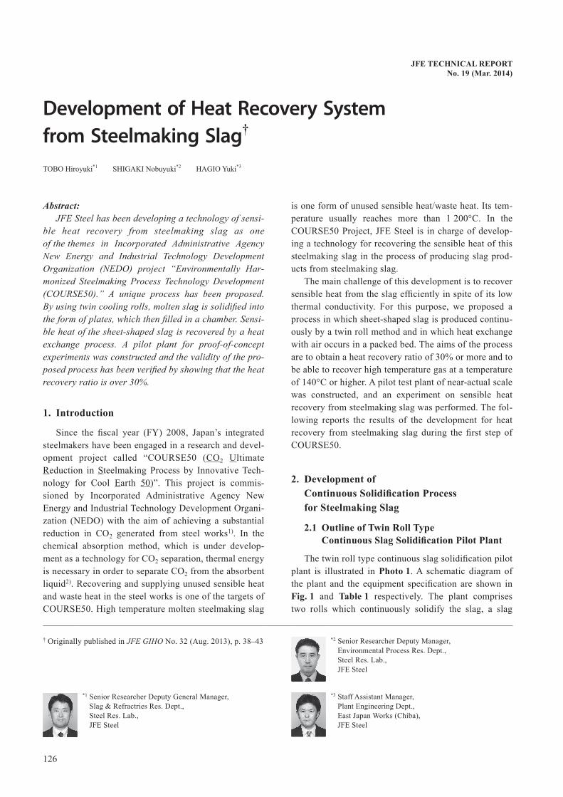
purpose thermal fluid analysis program FLUENT 6.3. The study assumed a constant cooling water flow vol-ume of 125 t/h in the entire roll and a clearance of 2.5 mm between the outer cylinder and the core.
The analysis results are shown in Fig.3. The flow velocity in the center of a flow channel with a clearance of 2.5 mm was 2.0 m/s with a 2 channel system and 1.5 m/s with a 1 channel system. Therefore, the 2 chan-nel system secures a higher cooling capacity, as it has a higher flow velocity. Based on this result, a double spi-ral-type 2 channel system was adopted. Views of the manufactured cooling rolls are shown in Photo2.
2.3 ResultsofContinuousSlagSolidificationExperiment
An experiment was performed with the twin roll type steelmaking slag solidification pilot plant by the follow-ing procedure. The tilting device was pushed up at a constant speed by the hydraulic cylinder, and molten slag was fed from the slag ladle to the gap between the two rolls via a chute. The two rolls were rotated in an outward direction, and the slag which cooled and solidi-fied on the roll surface adhered to the rolls and was drawn upward as the rolls rotated. After rotating approx-imately 180°, the slag dropped onto the conveyor. The solidified slag was transported by the conveyor and dropped from the end of the conveyor into a pit. In the pit, the slag was either cooled by water-sprinkling or allowed to cool by natural radiation, and was removed with a shovel. The temperature of the molten slag dis-charged from the ladle was measured with a radiation
thermometer. The temperature of the slag on the rolls and on the conveyor was measured by infrared thermog-raphy. In both cases, emissivity was assumed to be 0.92.
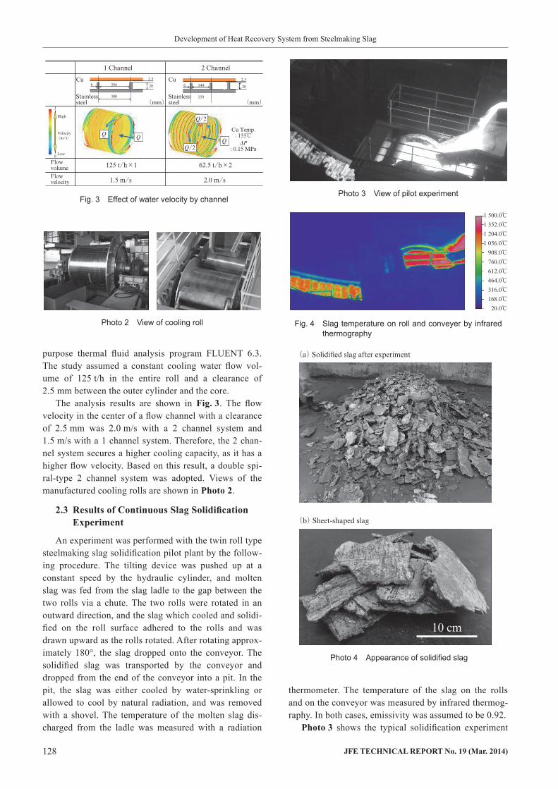
Photo3 shows the typical solidification experiment
Fig. 3 Effect of water velocity by channel
Photo 2 View of cooling roll
Photo 3 View of pilot experiment
Fig. 4 Slag temperature on roll and conveyer by infrared thermography
Photo 4 Appearance of solidified slag

JFETECHNICALREPORTNo.19(Mar.2014) 129
Development of Heat Recovery System from Steelmaking Slag
condition. In case that the molten slag have enough flu-idity, molten slag spread across the full width of the rolls and was continuously solidified with the rolls.
Figure4 shows an example of the slag surface tem-perature measurement results with an infrared thermog-raphy. The surface temperature of the slag decreases by 200–250°C when the slag solidifies on the roll. Temper-ature drop on the conveyor is slight, and the slag reaches the end of the conveyor at a temperature of around 1 100°C. This experiment confirmed that it is possible to secure the aimed slag temperature before sensible heat recovery, that is, 1 000°C or higher.
The solidified slag after cooling is shown in Photo4. The slag breaks down to smaller pieces as it drops from the end of the conveyor and into the pit where it is crushed. After some observation, it was noted that the surface of the slag that had been in contact with the roll was flat and hard and that its free surface was porous and rough.
The effect of the cooling roll rotation speed on the slag thickness is shown in Fig.5. Experiments were per-formed with cooling roll rotation speeds of 5–10 min−1. At the roll rotation speed of 10 min−1, the average slag thickness was 7–8 mm. Figure6 shows the water tem-perature at the inlet and outlet ends of the cooling roll.
The temperature of water passing through the roll while slag is being formed rises by approximately 30°C. Since this is within the design range of 70°C or less, the designed cooling capacity can be obtained.
3. DevelopmentofSlagHeatRecoveryProcess
3.1 DesignofSlagHeatRecoveryPilotPlant
The slag heat recovery pilot plant which was built in this development is a counterflow packed bed-type heat exchanger like the one used in coke dry quenching (CDQ). However, when compared in the same condi-tions (same volume and charging temperature), the amount of heat recovered by the slag heat recovery plant is only about 1/2 of that recovered in the CDQ. The amount of recovered heat is greater in CDQ because it also recovers the latent heat of the combustible gas that evolves from the coke. CDQ is therefore better in terms of economy. Moreover, in CDQ, the shape of the coke packing is lumpy, and can thus be approximated as spherical. This means that the heat transfer coefficient in the packed bed can be estimated by the Ranz-Marshall correlation, which is also used in blast furnace models, etc.4). However, the shape of the plate-shaped slag formed by solidification in the roll-forming pilot plant being different from that of the coke in CDQ, the heat transfer coefficient of the slag cannot be estimated by the existing model. In addition to this problem, fluidiza-tion of the packed slag is a concern if the flow volume of the heat recovery gas becomes excessive.
Therefore, before designing this slag heat recovery pilot plant, a precise evaluation of the heat transfer coef-ficient in the packed bed was made by a laboratory scale slag heat recovery experiment. In this experiment, the plate-shaped slag with the thickness of 7 mm, which were prepared for the experiment, were reheated and packed into the φ300 mm heat recovery experimental device, and we performed a heat recovery experiment with gas flow rates ranging from 60–200 l/min. As a result, it was deduced that the heat transfer coefficient in the packed bed of plate-shaped slag can be calculated more accurately by Eq. (1) than by the above-mentioned Ranz-Marshall coefficient. The Eq. (1), the Johnson-Rubesin equation5), which is an equation for heat trans-fer in a forced convection on a flat plate, is multiplied by a correction factor β = 0.25. The value of the correction factor compensates for the ease of gas flow and localiza-tion of the gas flow in a packed bed as a change in the heat transfer coefficient. In this research, β = 0.25 was obtained as the value that best represented the heat transfer behavior in a packed bed of plate-shaped slag.
Fig. 5 Effect of cooling roll rotation speed on slag thickness
Fig. 6 Temperature of cooling water for slag roll forming
130 JFETECHNICALREPORTNo.19(Mar.2014)
Development of Heat Recovery System from Steelmaking Slag
due to segregation of the gas flow in the heat recovery furnace, etc., the cross-sectional area was designed on the wider side (3 m2) relative to the above-mentioned gas flow volume, therefore maintaining the gas superfi-cial velocity to approximately 3 m/s.
3.2 OutlineofSlagHeatRecoveryPilotPlant
The production process and equipment specification of the steelmaking slag heat recovery pilot plant built in this project are shown in Fig.8 and Table2, respec-tively. Slag which has been solidified and formed into a plate-shape by the roll-forming pilot plant is transported by an apron conveyor. Then, part of the solidified slag discharged from the delivery side of the conveyor is sampled for use in heat recovery experiments by means of slide type chute, and the size of the remaining slag is broken down to the proper size by a simple crusher. The crushed slag is then supplied continuously to the heat recovery plant by a bucket elevator. Heat is exchanged by blowing air into the packed slag in the slag heat recovery chamber from two blowers. Heat recovery is then evaluated by measuring the temperature history of the recovered gas and the pressure drop in the packed bed. Since the bench-scale plant constructed here is not equipped with heat utilization equipment, such as a
.................................. (1)
Pr: Prandtl numberRe: Reynolds numberkg: Thermal conductivityLm: Average particle side lengthβ: Correction factor (= 0.25)
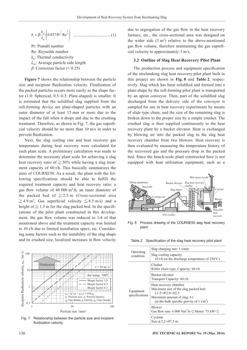
Figure7 shows the relationship between the particle size and incipient fluidization velocity. Fluidization of the packed particles occurs more easily as the shape fac-tor (1.0: Spherical, 0.5–0.3: Plate-shaped) is smaller. It is estimated that the solidified slag supplied from the roll-forming device are plate-shaped particles with an outer diameter of at least 15 mm or more due to the impact of the fall when it drops and due to the crushing treatment. Therefore, as shown in Fig. 7, the gas superfi-cial velocity should be no more than 10 m/s in order to prevent fluidization.
Next, the slag cooling rate and heat recovery gas temperature during heat recovery were calculated for each plant scale. A preliminary calculation was made to determine the necessary plant scale for achieving a slag heat recovery ratio of 30% while having a slag treat-ment capacity of 60 t/h. This basically summarizes the aims of COURSE50. As a result, the plant with the fol-lowing specifications should be able to fulfill the required treatment capacity and heat recovery ratio: a gas flow volume of 40 000 m3/h, an inner diameter of the packed bed of 2.5 m (Cross-sectional area 4.9 m2, Gas superficial velocity 8.5 m/s) and a height of 1.5 m for the slag packed bed. In the specifi-cations of the pilot plant constructed in this develop-ment, the gas flow volume was reduced to 1/4 of that mentioned above and the treatment capacity was limited to 10 t/h due to limited installation space, etc. Consider-ing some factors such as the instability of the slag shape and its crushed size, localized increases in flow velocity
hsb
kg
Lm
0.037Pr1
3 Re4
5=
Fig. 7 Relationship between the particle size and incipient fluidization velocity
Table 2 Specification of the slag heat recovery pilot plant
Operating condition
Slag charging rate: 1 t/min
Slag cooling capacity: 10 t/h (at the discharge temperature of 250°C)
Equipment specifications
ClusherRoller chain type, Capacity: 60 t/h
Bucket elevatorTransport Capacity: 60 t/h
Heat recovery chamberMaximum size of the slag packed bed: L1.5×W2.0×H2.5Maximum amount of slag: 6 t (at the bulk specific gravity of 1 t/m3)
BlowerGas flow rate: 6 000 Nm3/h×2 Motor: 75 kW×2
CycloneSize f 2.2×H7.5 m
Fig. 8 Process drawing of the COURSE50 slag heat recovery plant

JFETECHNICALREPORTNo.19(Mar.2014) 131
Development of Heat Recovery System from Steelmaking Slag
recovery ratio of heat recovery gas sensible heat with a temperature of 140°C or higher relative to the heating value of the molten slag (latent heat+sensible heat) obtained from the said temperature was 34%.
4. Conclusion
As part of the COURSE50 Project for CO2 reduction by the Japanese steel industry, a heat recovery experi-ment was performed with a directly-linked twin roll type steelmaking slag continuous solidification pilot plant and a slag heat recovery pilot plant. The experiment was carried out with slag from an actual steelmaking plant. A
boiler, etc., the heat recovery gas was cooled down by a water spray after evaluation of its properties. The gas is then released after de-dusting by a cyclone. As the pres-sure drop in the packed bed predicted from the Ergun equation is small at approximately to a maximum level of 10 kPa, the heat recovery chamber is designed as a square-like structure to simplify the slag charging and discharging mechanisms. An external view of the bench-scale slag heat recovery plant is shown in Photo5.
3.3 ResultsofSlagHeatRecoveryExperiment
Photo6 shows the slag during the slag heat recovery experiment. The photo on the top was taken from above the crusher. As the slag flows from the right side of the image to the left, it is successively crushed and flows into the charging hole of the bucket elevator. The photo on the bottom shows the interior of the heat recovery chamber during slag charging, as seen by the monitoring camera. Because transportation time by the bucket ele-vator is short, at approximately 20 s, the decrease in the slag temperature due to heat loss during transportation is slight at no more than 50°C.
Figure9 shows a graph of the actual temperature history of the heat recovery gas when heat recovery was performed with a blower flow volume rate of 6 000 m3/h with 1.7 t of slag charged into the heat recovery cham-ber. Even though the amount of packed slag was small compared to the rated capacity of 6 t, which corresponds to a height of 0.57 m for the slag bed (approximately 0.4 m from the tip of the blower discharge hole), it was possible to obtain a high temperature of 450°C for the heat recovery gas. The hatched area in Fig. 9 is the region where the recovery gas temperature is 140°C or more, which meets the objectives of COURSE50. Con-tinuous recovery of heat recovery gas at 140°C or higher was possible for 63 min. Since the molten slag tempera-ture measured by the radiation thermometer immediately before the start of the test was at 1 442°C, the heat
Photo 5 Exterior of the COURSE50 slag heat recovery plant
Photo 6 Hot slag plates charged for heat recovery
Fig. 9 Heat recovery ratio from the molten slag

132 JFETECHNICALREPORTNo.19(Mar.2014)
Development of Heat Recovery System from Steelmaking Slag
Development Organization (NEDO).
References
1) Miwa, T.; Okuda, H. Journal of the Japan Institute of Energy. 2010, vol. 89, p. 28–35.
2) Matsuzaki, S.; Higuchi, K.; Shinotake, A.; Saito, K. SCANMET IV. 2012, p. 45–49.
3) Akashi, Tetsuo; Ichikawa, Tetsuya; Suzuki, Nagayoshi. JFE Giho. 2008, no. 19, p. 61–64.
4) Hatano, Michiharu; Kurita, Kooichi. Tetsu-to-Hagané. 1980, vol. 66, p. 1898–1907.
5) Johnson, H. A.; Rubesin, M. W. Transactions of the ASME. 1949, vol. 71, no. 5, p. 447–456.
maximum of 1.7 t of sheet-shaped slag with a thickness of 7 mm, which was solidified continuously by the roll-forming pilot plant, was charged to the slag heat recov-ery pilot while still in a high temperature condition over 1 000°C. As a result, heat recovery ratio from molten slag was obtained 34%
These results were obtained as part of the “Course50 (CO2 Ultimate Reduction in Steelmaking Process by Innovative Technology for Cool Earth 50),” which is a project commissioned by Japan’s Incorporated Adminis-trative Agency New Energy and Industrial Technology