development of knee joint for a motor-actuated...
TRANSCRIPT

DEVELOPMENT OF KNEE JOINT FOR A
MOTOR-ACTUATED KNEE PROSTHESIS
MOHD FAIZ BIN MISPAN
FACULTY OF ENGINEERING
UNIVERSITY OF MALAYA
KUALA LUMPUR
2014

DEVELOPMENT OF KNEE JOINT FOR A
MOTOR-ACTUATED KNEE PROSTHESIS
MOHD FAIZ BIN MISPAN
RESEARCH REPORT SUBMITTED IN PARTIAL
FULFILLMENT OF THE REQUIREMENT FOR THE
DEGREE OF MASTER OF ENGINEERING
FACULTY OF ENGINEERING
UNIVERSITY OF MALAYA
KUALA LUMPUR
2014

UNIVERSITI MALAYA
ORIGINAL LITERARY WORK DECLARATION
Name of Candidate: MOHD FAIZ BIN MISPAN (I.C/Passport No:
Registration/Matric No: KGL120007
Name of Degree: MASTER OF ENGINEERING (BIOMEDICAL)
Title of Project Paper/Research Report/Dissertation/Thesis (“this Work”):
DEVELOPMENT OF KNEE JOINT FOR A MOTOR-ACTUATED KNEE PROSTHESIS
Field of Study:
I do solemnly and sincerely declare that:
(1) I am the sole author/writer of this Work;
(2) This Work is original; (3) Any use of any work in which copyright exists was done by way of fair dealing and for
permitted purposes and any excerpt or extract from, or reference to or reproduction of
any copyright work has been disclosed expressly and sufficiently and the title of the
Work and its authorship have been acknowledged in this Work;
(4) I do not have any actual knowledge nor do I ought reasonably to know that the making
of this work constitutes an infringement of any copyright work;
(5) I hereby assign all and every rights in the copyright to this Work to the University of
Malaya (“UM”), who henceforth shall be owner of the copyright in this Work and that any
reproduction or use in any form or by any means whatsoever is prohibited without the
written consent of UM having been first had and obtained; (6) I am fully aware that if in the course of making this Work I have infringed any copyright
whether intentionally or otherwise, I may be subject to legal action or any other action
as may be determined by UM.
Candidate’s Signature Date
Subscribed and solemnly declared before,
Witness’s Signature Date
Name:
Designation:

1
Abstract
A well-designed lower limb prosthesis is required in order to allow an amputee to return to
healthy locomotion. A complete set of the prosthesis for transfemoral amputee includes a
socket which is custom fit to the residual limb, a prosthetic knee unit, a shank connecting
the knee unit to a prosthetic ankle, and a prosthetic foot. The purpose of this project is to
improve the initial design of a microcontroller-based transfemoral prosthesis which was
unable to reach the designated rotational speed intended for a functional use, and had low
aesthetic value. The improvement focuses on designing a new mechanism on the knee unit
by using a pre-existed motor, a socket, and the prosthetic foot available from the previous
design. This includes mimicking the normal limb function and to enhance the range of
motion of this knee prosthesis. For aesthetic reason, a new cover of the shank will be
designed. There are a few criteria that need to be fulfilled at the end of this project such as
the new proposed knee unit should be able to bend up to 120O and has enough strength to
withstand the amputee’s body weight. A computer aided design (CAD) software known as
SolidWorks 2013 was used to design every single component of the knee unit and the
shank cover. Then, each component will be assembled and the mechanism of the knee unit
will be simulated in order to visualize the expected motion or movement of this new knee
prosthesis. The materials used was selected by considering the cost and the properties of
that material. Finite element analysis (FEA) was performed and the results were evaluated
to determine if the proposed prosthesis can withstand certain loads. In the end, all results
were discussed and evaluated to check if the design has fulfilled the goals of this project.

2
Abstrak
Kaki palsu diperlukan oleh individu tanpa kaki untuk membolehkan mereka bergerak
secara normal. Satu set kaki palsu yang sempurna harus mempunyai soket, unit lutut palsu,
betis palsu, dan tapak kaki palsu. Projek ini dilaksanakan untuk menambah baik rekabentuk
pertama kaki palsu yang tidak mencapai kelajuan yang diperlukan untuk melipat kaki palsu
tersebut. Ia juga mempunyai nilai estetik yang rendah. Penambahbaikan difokuskan kepada
merekabentuk satu mekanisma baru dengan menggunakan motor dan soket yang sedia ada.
Rekacipta tersebut haruslah meniru fungsi kaki manusia yang normal serta dapat
meningkatkan sudut semasa melipat kebelakang unit lutut palsu tersebut. Nilai estetik unit
lutut palsu tersebut harus ditingkatkan dengan merekabentuk satu kerangka baru. Reka
bentuk kaki palsu tersebut haruslah mempunyai keupayaan untuk dilipatkan sehingga
mencecah 120 darjah and mempunyai kekuatan untuk menampung berat badan mana-mana
individu tanpa kaki. Perisian rekabentuk berbantukan komputer (CAD) yang dikenali
sebagai SolidWorks 2013 telah digunakan untuk merekabentuk setiap bahagian lutut palsu
tersebut. Mekanisma pergerakan unit lutut palsu tersebut telah disimulasikan untuk melihat
bagaimana ia bergerak. Bahan yang digunakan untuk membina unit lutut palsu tersebut
akan dipilih dengan mengambilkira kos dan ciri-ciri bahan tersebut. Analisa elemen
terbatas (FEA) telah dilakukan ke atas unit lutut palsu tersebut dah keputusannya telah
disemak untuk memastikan ianya mampu menampung beban badan mana-mana individu
tanpa kaki. Pada akhir projek, kesemua keputusan telah dibincangkan untuk menyemak
sama ada rekabentuk tersebut telah memenuhi matlamat projek ini.

3
Acknowledgement
I would like to take this opportunity to express my profound gratitude and deep regards to
my supervisor, Dr. Nur Azah Binti Hamzaid for her exemplary guidance, monitoring, and
constant encouragement throughout the course of this project. The blessing, help, and
guidance given by her time to time shall carry me a long way in the journey of life on
which I am about to embark. Without her supervision and friendly help this project would
not have been possible.
I want to express my deep gratitude to my parents because of their understanding,
encouragement, and personal guidance which provided a good support for this thesis
project. The countless times they have spent to fire up my spirit during my hectic schedule
will not be forgotten.
Lastly, to all family members, friends and coursemates, all your supports are gratefully
acknowledged.

4
Table of Contents
Abstract .................................................................................................................................. 1
Abstrak ................................................................................................................................... 2
Acknowledgement.................................................................................................................. 3
Table of Contents ................................................................................................................... 4
List of Figures ........................................................................................................................ 6
List of Tables.......................................................................................................................... 9
List of Symbols and Abbreviations ...................................................................................... 10
Chapter 1. INTRODUCTION ......................................................................................... 11
1.1. Overview ............................................................................................................... 11
1.2. Scope of Work ....................................................................................................... 20
1.3. Problem Statement ................................................................................................ 21
1.4. Objectives of the Project ....................................................................................... 21
1.5. Project Schedule .................................................................................................... 22
1.6. Organisation of the Project .................................................................................... 23
Chapter 2. LITERATURE REVIEW............................................................................... 24
2.1. Research in Transfemoral Prostheses .................................................................... 24
2.2. Commercial Microcontroller Prosthetic Knees ..................................................... 35
Chapter 3. METHODOLOGY ......................................................................................... 40
3.1. Introduction ........................................................................................................... 40
3.2. Observation, Research, and Collecting Information ............................................. 41
3.3. Identifying the Problem Statement ........................................................................ 45
3.4. Identification of Objectives ................................................................................... 45

5
3.5. Identification of the Design Criteria ...................................................................... 45
3.6. Rough idea for the design ...................................................................................... 52
3.7. Finalize and Modelling of the Design ................................................................... 60
3.8. Simulation and Analysis of the Design ................................................................. 61
Chapter 4. RESULTS ...................................................................................................... 64
4.1. The Design ............................................................................................................ 64
4.2. The Simulation and Analysis ................................................................................ 73
4.3. Estimated Total Weight and Total Cost for Fabrication ....................................... 79
Chapter 5. DISCUSSIONS .............................................................................................. 83
5.1. The Design ............................................................................................................ 83
5.2. The Simulation ...................................................................................................... 87
5.3. Suggestion for Future Research............................................................................. 88
Chapter 6 Conclusion ..................................................................................................... 89
References ............................................................................................................................ 90
6
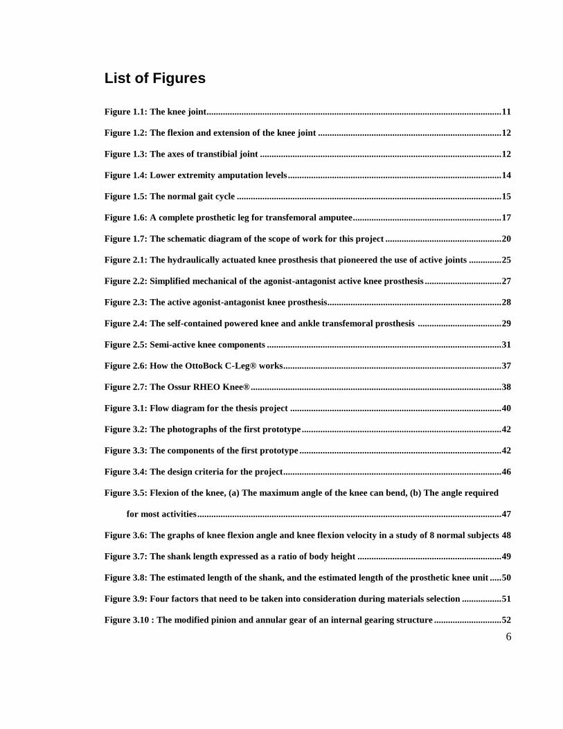
List of Figures
Figure 1.1: The knee joint............................................................................................................................... 11
Figure 1.2: The flexion and extension of the knee joint ............................................................................... 12
Figure 1.3: The axes of transtibial joint ........................................................................................................ 12
Figure 1.4: Lower extremity amputation levels ............................................................................................ 14
Figure 1.5: The normal gait cycle .................................................................................................................. 15
Figure 1.6: A complete prosthetic leg for transfemoral amputee................................................................ 17
Figure 1.7: The schematic diagram of the scope of work for this project .................................................. 20
Figure 2.1: The hydraulically actuated knee prosthesis that pioneered the use of active joints .............. 25
Figure 2.2: Simplified mechanical of the agonist-antagonist active knee prosthesis ................................. 27
Figure 2.3: The active agonist-antagonist knee prosthesis........................................................................... 28
Figure 2.4: The self-contained powered knee and ankle transfemoral prosthesis .................................... 29
Figure 2.5: Semi-active knee components ..................................................................................................... 31
Figure 2.6: How the OttoBock C-Leg® works .............................................................................................. 37
Figure 2.7: The Ossur RHEO Knee® ............................................................................................................ 38
Figure 3.1: Flow diagram for the thesis project ........................................................................................... 40
Figure 3.2: The photographs of the first prototype ...................................................................................... 42
Figure 3.3: The components of the first prototype ....................................................................................... 42
Figure 3.4: The design criteria for the project .............................................................................................. 46
Figure 3.5: Flexion of the knee, (a) The maximum angle of the knee can bend, (b) The angle required
for most activities ................................................................................................................................... 47
Figure 3.6: The graphs of knee flexion angle and knee flexion velocity in a study of 8 normal subjects 48
Figure 3.7: The shank length expressed as a ratio of body height .............................................................. 49
Figure 3.8: The estimated length of the shank, and the estimated length of the prosthetic knee unit ..... 50
Figure 3.9: Four factors that need to be taken into consideration during materials selection ................. 51
Figure 3.10 : The modified pinion and annular gear of an internal gearing structure ............................. 52

7
Figure 3.11: The diagram of the first rough idea ......................................................................................... 53
Figure 3.12: The illustration of the knee flexion at certain degrees ............................................................ 54
Figure 3.13: The new proposed spindle with 2 mm pitch to pitch value .................................................... 54
Figure 3.14: The second rough idea ............................................................................................................... 55
Figure 3.15: Some calculation of the second rough idea .............................................................................. 56
Figure 3.16: (a) The compound gear with ratio of 2, (b) The idler gear, (c) The gear train (2D view), and
(d) The gear train (3D view) ................................................................................................................. 57
Figure 3.17: The weight concentration at (a) inferior side, and (b) superior side of the prosthetic knee 58
Figure 3.18 – The illustration of weight of the motor and the spindle ........................................................ 58
Figure 3.19: Example of plastic chain ........................................................................................................... 59
Figure 3.20: The configuration of the third rough idea ............................................................................... 59
Figure 3.21: The illustration of knee flexion of the rough idea 3 at certain degrees ................................. 60
Figure 3.22: The view of SolidWorks 2013 software .................................................................................... 61
Figure 3.23: The situation of an amputee uses the prosthetic knee while lifting up his normal leg ......... 62
Figure 3.24: The application of a load of 800 N on the prosthetic knee unit .............................................. 63
Figure 4.1: The complete structure of the prosthetic leg for this project ................................................... 64
Figure 4.2: The percentage of the prosthetic knee at thigh and shank ....................................................... 65
Figure 4.3: The assembled view (a) and the exploded view (b) of the prosthetic knee unit ...................... 65
Figure 4.4: The shapes of the (a) C-block and (b) L-block .......................................................................... 66
Figure 4.5: How the blocks create moments at the knee joint ..................................................................... 66
Figure 4.6: The connections of the blocks ..................................................................................................... 67
Figure 4.7: The two sides of the spine ............................................................................................................ 68
Figure 4.8: The connections of the spine ....................................................................................................... 68
Figure 4.9: The role of the motor cap and the O-nut in rotating the knee joint ........................................ 69
Figure 4.10: The flexion of the prosthetic knee at certain degrees.............................................................. 70
Figure 4.11: The orientation of the CS connector and the C-clamps.......................................................... 71

8
Figure 4.12: The different views of the shank cover .................................................................................... 72
Figure 4.13: The symmetrical parts of the shank cover ............................................................................... 72
Figure 4.14: The stress Von Mises analysis for all three materials ............................................................. 75
Figure 4.15: The displacement analysis of all three materials ..................................................................... 76
Figure 4.16: High stress distribution at the gap between the C-block and the spine ................................ 77
Figure 4.17: Some screenshots of the animation video ................................................................................. 78
Figure 4.18: The parts to be fabricated ......................................................................................................... 79
Figure 4.19: The formula in estimating the total weight of the prosthetic knee ........................................ 80
Figure 4.20: The estimation of weight of the available parts ....................................................................... 80
Figure 5.1: The length from the knee joint to the bottom of the prosthetic knee ...................................... 86
Figure 5.2: The load experience by the C-block and the spine .................................................................... 87

9
List of Tables
Table 1.1: Types of prothetic knees ............................................................................................................... 17
Table 1.2: The time schedule of the project .................................................................................................. 22
Table 2.1: Summary of some previous works in transfemoral prostheses ................................................. 31
Table 2.2: The classification and comparion of input method, control, and actuation for some of the
prosthetic knees ...................................................................................................................................... 38
Table 3.1: Analysis of the first prototype. ..................................................................................................... 43
Table 3.2 - The mean height and body weight in a national sample of Malaysian adults ......................... 49
Table 4.1 - The summary of the static stress analysis and the displacement analysis ............................... 77
Table 4.2: The estimated weight and cost for different types of materials ................................................. 82
Table 5.1: The comparison of three rough ideas .......................................................................................... 83
Table 5.2: The design criteria checklist ......................................................................................................... 85

10
List of Symbols and Abbreviations
Acrylonitrile butadiene styrene ABS
Agonist-antagonist active knee prosthesis AAAKP
Computed Aided Design CAD
Finite Element Analysis FEA
Lower limb amputation LLA

11
Chapter 1. INTRODUCTION
1.1. Overview
1.1.1. The Knee Joint
The knee is where the upper and lower legs join together. It plays crucial roles in the body,
and provides the bending motion that allows us to walk. It is the largest synovial joint in the
body. It consists of two joints which known as tibiofemoral joint (an articulation between
femur and tibia), and patellofemoral joint (an articulation between the patella and femur) as
illustrated in Figure 1.1. The knee is one of the most mechanically vulnerable areas. It is
due to the forces and leverage which act on the joint both in terms of chronic weight
bearing problems, and also in terms of traumatic impacts (Kingston, 2001).
Figure 1.1: The knee joint (Adapted from NucleusMedical Art, Inc., 2012)

12
Two major movements of the knee are flexion and extension as illustrated in Figure 1.2.
Meanwhile, Figure 1.3 illustrates on how the bicondylar mechanism of the transfemoral
joint. This joint allows flexion and extension through the transverse axis with limited
rotation through longitudinal axis (Kingston, 2001)
Figure 1.2: The flexion and extension of the knee joint (Adapted from Wikipedia, 2013)
Figure 1.3: The axes of transtibial joint (Adapted from Kingston, 2001)
13
1.1.2. Lower Limb Amputation
An amputation can be defined as removal of the limb or outgrowth of the body (Dorland &
Anderson, 2003). A decision to amputate someone is made when an injured limb cannot be
recovered to function after disease or trauma. An amputation is also known as a life-saving
operation when no other choices available. It must not be considered as a failed treatment.
The amputation is one of the oldest surgical procedures that has been practiced by surgeons
for decades. The development of prosthetic design and specific rehabilitation programmes
for people with limb loss was intensified after World War II (Bowker & Pritham, 2004).
A lower limb amputation (LLA) can be categorized into a major or minor amputation. A
major amputation is performed proximal to the ankle joint. Meanwhile, a minor amputation
is one performed distal to the ankle joint. Transfemoral amputation, knee disarticulation,
and transtibial amputations are three most common levels of amputation as illustrated in
Figure 1.4. Most of the LLA were reported due to peripheral vascular disease. Nowadays,
this incidence involves 12 to 44 per 100000 persons annually. A person with diabetes
mellitus has a higher risk of amputation compared to a normal person (Ephraim &
Dillingham, 2003). One of the main concerns with the level of amputation is the energy
cost of the prosthetic limb gait. A higher level amputation requires more energy during
ambulation compared to the ambulation of lower level amputation (Waters & Mulroy,
1999).

14
Figure 1.4: Lower extremity amputation levels (Reproduced from Burns, 2010)
1.1.3. Human Gait Cycle
Walking is defined as a method of locomotion involving the use of two legs in order to
provide support and propulsion. A repetitive sequence of limb motion is required to move
the body forward while simultaneously maintaining stance stability. Gait represents the
manner of walking of any individual, rather than the actual walking process. The gait cycle
is known as a period of time between two consecutive heel contacts of the same foot. Let
say, if someone starts with the right foot contacting the ground, then the cycle ends when
the right foot makes contact with the ground again. There are two phases in the cycle,
which are stance phase and swing phase.

15
The stance phase is defined as part of the cycle when the foot is in contact with the ground,
which comprises of 62 percent of the cycle. It begins with initial foot strike and it ends with
toe-off. Meanwhile, the swing phase is known as an interval in which the foot is not contact
with the ground. It comprises of 38 percent of the gait cycle. The swing phase is the phase
when all portions of the foot are in forward motion. Figure 1.5 is the diagram to represent
the gait cycle. The gait pathologies and walking speed affect the period of time to complete
the gait cycle (Larsson et al., 1980).
Figure 1.5: The normal gait cycle (Reproduced from Liikavainio, 2010)

16
For transfemoral amputees, gait patterns change in comparison with normal gait due to
absence of muscles in the prosthetic limb. It leads the prosthetic limb to have uncontrolled
flexion during stance phase. This can be avoided by substituting the prosthetic limb with a
substitute stabilization device. At the same time, a prosthetic knee should be able to allow
and control mobility between the thigh and lower leg during swing phase (Sapin & Goujon,
2008).
1.1.4. Types of Prosthetic Knees
The quality of life of an amputee can be improved by fitting his/her residual limb with an
appropriate prosthetic leg. A common prosthetic leg for a transfemoral amputee comprises
a custom fitted socket to the residual thigh, a knee joint, an ankle, a foot, and some
connecting components as illustrated in Figure 1.6. A good prosthetic knee should mimic
the behaviour of the biological knee.
Nowadays, many types of prosthetic knees are available in the market. They come from
simple, purely mechanical devices up to sophisticated microprocessor controlled systems.
Typically, a mechanical knee trades increased mobility for decreased stability (Lambrecht,
2008). This is where a prosthetist plays his role in helping the amputees to find a suitable
balance for the individual amputee’s muscular coordination. The types of prosthetic knees
are summarized in Table 1.1.

17
Figure 1.6: A complete prosthetic leg for transfemoral amputee (Reproduced from Lambrecht, 2008)
Table 1.1: Types of prothetic knees (Adapted from Lambrecht, 2008)
Types of prosthetic knees Descriptions
Single axis knee
The most basic prosthetic knee.
Comprises a single pivot between the thigh socket and shank.
As long as the leg is straight at heel strike, the knee will not
buckle during stance.
The amputee may need to exert more hip extension torque to
keep the knee over center during mid to late stance.

18
Table 1.1, continued
Types of prosthetic knees Descriptions
Locking knees
Kept straight during walking.
Incorporates a cable or lever release to allow the knee to bend
for sitting.
A locking knee is fitted when amputee lacks the hip control to
stabilize a bending knee.
May cause inefficient still legged gait.
No chance of the knee buckling and causing the amputee to
fall.
Stance control knees
Single axis knee with friction break (self-lock).
A load from the amputee’s body weight makes the friction
brake engages and preventing the knee from buckling.
The brake disengages when the load is removed, which allows
the shank swings freely.
It does not allow knee flexion in terminal stance to initiate
swing until the knee is fully unloaded.
Polycentric knees
Consists of four bar mechanism which move in the sagittal
plane.
Near the straight position of the knee, the effective pivot lies at
the posterior of the load path for safe early stance loading.
During terminal stance, it buckles easily to initiate the swing.
19
Table 1.1, continued
Types of prosthetic knees Descriptions
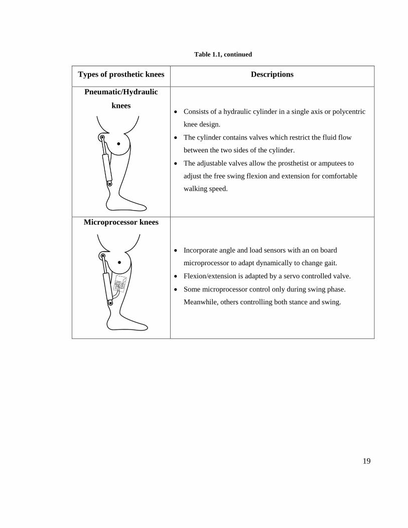
Pneumatic/Hydraulic
knees
Consists of a hydraulic cylinder in a single axis or polycentric
knee design.
The cylinder contains valves which restrict the fluid flow
between the two sides of the cylinder.
The adjustable valves allow the prosthetist or amputees to
adjust the free swing flexion and extension for comfortable
walking speed.
Microprocessor knees
Incorporate angle and load sensors with an on board
microprocessor to adapt dynamically to change gait.
Flexion/extension is adapted by a servo controlled valve.
Some microprocessor control only during swing phase.
Meanwhile, others controlling both stance and swing.

20
1.2. Scope of Work
A study of a microprocessor prosthetic leg is being carried out by a group of researchers
from the Department of Biomedical Engineering, University of Malaya. The study aims to
develop a bionic leg that detects user intention, to create a leg that can think by itself, and to
develop knee with controlled action. The main objective of that study is to design a new
microcontroller prosthetic knee with implanted piezoelectric materials at the socket as
illustrated in Figure 1.7. That is the big picture of the study, while this thesis project
focuses only in developing the mechanical structure of the prosthetic knee joint in terms of
improving the performance of the initial design, and to increase the aesthetic value of the
bionic leg. The materials of each component of the prosthetic knee joint will be selected
carefully. The prosthetic knee joint was simulated to study its strength, and mobility.
Figure 1.7: The schematic diagram of the scope of work for this project

21
1.3. Problem Statement
There are a few things of the initial design that needs to be improved. The actuated motor
was purchased by focusing too much on torque of the actuated motor. The speed of the
motor seemed to have been overlooked. The initial design flexes in a very slow motion. It
takes approximately 40 seconds to bend the knee from 0 – 90O. The prosthetic knee should
be able to flex very quickly in order to allow the amputee to move fast. Furthermore, the
range of motion up to 90O does not mimic the range of motion of human biological knee.
The length of the initial design was approximately 450 mm. It is bulky and unsuitable to be
used for Malaysian amputees. The long cylindrical shell of the initial design does not look
appealing. To allow the prosthetic knee to look nicer, a new cover of the prosthetic knee
was proposed. Although the speed of the available actuated motor is very slow, the
proposed design of the prosthetic knee must be taken into account. The proposed design
should be able to increase the knee flexion speed without changing or modifying the
actuated motor.
1.4. Objectives of the Project
The objectives that are set to be achieved at the end of this project are as follows:
1. To improve the initial design of the microcontroller prosthetic knee in terms of its
functionality, size, cost, and weight.
2. To evaluate the strength and range of motion of the proposed design of the
microcontroller prosthetic knee.

22
1.5. Project Schedule
The time schedule of the thesis project is given in Table 1.2.
Table 1.2: The time schedule of the project

23
1.6. Organisation of the Project
In Chapter 1, Introduction, the basic information of the knee joint and lower limb
amputation are described. Different types of prosthetic knees are tabulated in a table.
Furthermore, the problems of initial design of the prosthetic knee are discussed and the
objectives of the project are listed down. The project schedule shows the management of
this project throughout the 14 weeks.
In Chapter 2, Literature Review, the several studies in transfemoral prostheses are
reviewed. A few different types of commercial microcontroller prosthetic knees are also
mentioned.
In Chapter 3, Methodology, the steps taken for this project are explained. All the steps are
planned properly before the project get started. The sequences of the steps are summarized
in the flowcharts for better understanding.
In Chapter 4, Result, the proposed design of the prosthetic knee is presented. Each
component of the design is elaborated based on their functions and properties. The
successful of the simulation models of FEA with different materials are shown. The
estimated weight and fabrication cost of the design are calculated.
In Chapter 5, Discussion, the further explanation of the design and the simulation models
are discussed. The future works for improvement of the project are suggested.
In Chapter 6, Conclusion, the whole project is briefly summarized.

24
Chapter 2. LITERATURE REVIEW
In the past, there were not many devices available for people who lost their lower limb.
Most of the time, they use wheelchairs, walkers, and crutches to perform their daily
activities. Development of knee prostheses has been taking place for decades. It started
with purely mechanical systems to systems that use microprocessor control. Nowadays, the
amputees can take advantage in technology and medical science by wearing
microcontroller-based lower limb prosthetics. Many efforts have been made to develop a
microprocessor transfemoral prosthesis in order to allow the amputees to have a better
quality of life. There are different types of actuation methods have been introduced,
including electric motors, hydraulic, and pneumatics.
2.1. Research in Transfemoral Prostheses
Many studies in transfemoral prostheses have been carried out for many years. It started in
1970s, where a tethered electrohydraulic transfemoral prosthesis became a pioneer of active
joints in transfemoral prosthesis. The design was introduced by Flowers and Mann. It
consisted of a hydraulic actuated knee joint tethered to a hydraulic power source and off-
board electronics, and computation as shown in Figure 2.1. An ‘echo control’ scheme for
gait control was developed where a modified knee trajectory from the sound leg was played
back on the contralateral side. The device was designed for able bodied subjects and it
could not be tested on an amputee. The device was attached to the able bodied subjects,

25
with their knees in extreme flexion. The subjects had difficulty to walk due to unnatural
configuration of the leg (Flowers & Mann, 1977).
Figure 2.1: The hydraulically actuated knee prosthesis that pioneered the use of active joints
(Reproduced from Flowers & Mann, 1977)
At the beginning of the 21st century, a study of direct actuation of the joint by an AC servo
motor was introduced by Hata. A complex model to simulate human walking gait was
developed together with a few different stiffness mechanism to minimize the torque
required when the leg was in a static position. The design was proven to be able to provide
roughly 100 Nm of torque and 6.5 rad sec-1 of a rotational velocity. Unfortunately, the
design required a DC/AC inverter to make the design portable (Hata, 2002).

26
In 2007, a powered prosthesis using a DC electric motor was designed by Fite et al. Instead
of actuating the knee joint directly, the motor turned a ball screw in slider-crank
mechanisms. Without using heavy gearboxes, the design allowed the motor to generate a
large joint torque. A combination of 150 W DC motor and ball screw was able to provide
an output force of 1880 N. The design had a capability to provide torque for walking and
stair climbing for users up to 85 kg. The mass of the prosthesis was approximately 3 kg,
and it must be tethered to a workstation to provide power and control. A large quantity of
batteries was required to operate the prosthesis, which made the system difficult to use
(Fite, 2007).
The usage of actuated motors was continued where a series of elastic actuators in an
agonist-antagonist configuration was designed by Martinez and Herr. They called the
design as agonist-antagonist active knee prosthesis (AAAKP). The knee joint was
controlled by the two actuators together as shown in Figure 2.2, and the forces of the
actuators could be varied to adjust the stiffness of the joint. The design consisted of a motor
lead screw combination, which connected to a linear spring. This design allowed a good
control of the knee joint, but the actuator was fairly heavy with a weight of 1.13 kg. It also
had a small output force (750 N), where it required a large amount of moment arm to
produce enough torque as needed by the knee joint (Martinez et al., 2008).

27
Figure 2.2: Simplified mechanical of the agonist-antagonist active knee prosthesis (Reproduced from
Martinez et al., 2008)
The AAAKP inspired by the muscle anatomy of the natural human knee joint. The
prototype of the AAAKP is shown in Figure 2.3. The knee joint was controlled by a series
of cables which connected to a linear carriage, which free to move along the length of the
device. The carriage could be moved on either side depending on the flexion or extension
of the springs which driven by an electric motor. An aluminium structure was selected to
support the actuation mechanisms, which resembled the shape of the knee and shin. A
brushed DC motor was selected in providing sufficient power for both level ground
walking, and more extreme tasks, such as stair climbing (Martinez et al., 2008).

28
Figure 2.3: The active agonist-antagonist knee prosthesis (Reproduced from Martinez et al., 2008)
Instead of an actuated motor that has been used by many studies, a pneumatic cylinder was
introduced by Sup et al. to act as a prosthetic actuator. The design consisted of a powered
prosthesis with actuated knee and ankle joints. The actuators were placed in a slider-crank
configuration, similar to the slider-crank by Fite (2007). The design could generate a torque
curve for a 75 kg user. Since pneumatic actuators were used, the joint compliance was
controlled by adjusting the pressure in the cylinder. The authors proposed to use a chemo-
fluidic actuation (monopropellant and catalyst) to produce pressurized gas, which is more
energy dense (Sup, Bohara, & Goldfarb, 2008).
In 2009, Sup et al. once again produced another powered prosthesis. The initial design was
improved by replacing the pneumatic cylinder with a motor-ball screw actuators. The

29
design is illustrated in Figure 2.4. A compression spring was added into the design of the
ankle actuator, which similar to Martinez and Herr. The spring helped in generating
additional force to be produced at toe-off of the foot. The new design has a mass of 4.2 kg.
It could support up to 85 kg of a user over a distance of 9 km (Sup et al., 2009).
Figure 2.4: The self-contained powered knee and ankle transfemoral prosthesis (front and side views)
(Reproduced from Sup, 2009)
In the same year of Sup et al. improving their design, Lambrecht and Kazerooni developed
a semi active hydraulic prosthesis similar to commercial products, such as C-Leg® and

30
Rheo Knee ®. The design played a role during large portions of the gait cycle by adjusting
the joint dumping to improve swing control. A hydraulic pump assisted the knee flexion
and extension to ensure a normal gait cycle was maintained. It provided short term power
for different types of daily activities, such as standing and stair climbing. The mass of the
prosthesis was less than 4 kg. It used a combination of active and passive modes which
enable users to walk up to 3000 steps per day. The prosthesis could not contribute to a large
amount of positive work during walking. It was designed mainly to assist a user with a
powered swing and stance (Lambrecht & Kazerooni, 2009).
The hydraulic knee prosthesis (by Lambrecht and Kazerooni) was assembled from several
components as illustrated Figure 2.5. A residual limb of an amputee would be fit onto a
conventional prosthetic socket, which attached to the thigh link of the knee. The thigh was
hinged to a shank like, where it was connected to an ankle foot prosthesis by a conventional
pylon. The hydraulic manifold (contains a hydraulic actuator) connected the thigh and
shank links to complete the linkage. The gear pump (acted as a drive motor), a control
valve with fluid passages, passive elements, and sensors were connected by the hydraulic
manifold. The drive motor, pump displacement, manifold passageways, cylinder size, and
linkage geometry were designed carefully to achieve the desired performance (Lambrecht
& Kazerooni, 2009)
The development of the transfemoral knee prostheses are briefly explained above. In
general, every study showed different designs and mechanisms. Table 2.1 shows the
mechanical characteristic from some of studies of transfemoral knee prostheses.

31
Figure 2.5: Semi-active knee components (Reproduced from Lambrecht and Kazerooni, 2009)
Table 2.1: Summary of some previous works in transfemoral prostheses
Study 1 Mechanism
Martinez et al.
(2008)
Driven by a set of cables with two motors (extension and flexion)
Range of
motion
Material
used Weight Dimension Testing
0 – 120O Aluminium Unknown Unknown Simulation
only
(Reproduced from Martinez et al., 2008)

32
Table 2.1, continued
Study 2 Mechanism
Lambrecht
(2008)
Uses hydraulic manifold to flex the knee
Range of
motion
Material
used Weight Dimension Testing
0 – 120O
Carbon fiber
(frame),
aluminium
(holders)
Unknown Unknown Tested on
amputee
(Reproduced from Lambrecth, 2008)

33
Table 2.1, continued
Study 3 Mechanism
Sup
(2008)
Uses double-acting pneumatic actuators (ankle and knee)
Range of
motion
Material
used Weight Dimension Testing
0 – 110O 7075-T6
Aluminium Unknown Unknown
Tested on a
healthy
subject
(Reproduced from Sup et al., 2008)

34
Table 2.1, continued
Study 4 Mechanism
Fite
(2007)
Uses a 150 W brushed DC motor (Maxon model RE40)
Range of
motion
Material
used Weight Dimension Testing
Unknown Unknown 3.05 Kg Unknown
Tested on a
healthy
person
(Reproduced from Fite, 2007)

35
Table 2.1, continued
Study 5 Mechanism
Waycaster
(2010)
Uses two actuators (knee and ankle) and torsional spring for easier
adjustability of the leg length.
Range of
motion
Material
used Weight Dimension Testing
0 – 110O
6061 T6
Aluminium
alloy
Unknown Unknown
Tested on a
healthy
subject
(Reproduced from Waycaster, 2010)
2.2. Commercial Microcontroller Prosthetic Knees
Several different types of prosthetic knees are commercially available today. They range
from simple mechanical joints to advanced microcontroller joints. Each one of them has its

36
own strength and weaknesses based on the activity level and condition of the user. This
section describes several types of commercial microcontroller prosthetic knees and their
working method.
Some of the most commercially successful of microcontroller prosthetic knees are the
OttoBock C-Leg® (OttoBock, 2014), the Ossur RHEO Knee® (Ossur, 2014), and the
Freedom Innovations Plié Knee® (Innovations, 2014). They use a hydraulic joint that is
controlled by a microcontroller. They allow some variable damping throughout the swing
phase. They also have the ability to lock the knee joint in any position. The joint angle can
be determined by using a potentiometer. Then, based on several programmes of walking
modes, a stepper motor will automatically adjusts the size of an orifice in a hydraulic
cylinder. This allows for dynamically variable damping, which can be adjusted depending
on different types of activities.
In 1997, the OttoBock C-Leg® was first introduced to the public and it made a history with
the first microprocessor controlled knee joint in the world. It has capabilities to regulate not
just the swing phase control, but also the locking during stance phase. Two sensors at the
knee and ankle supply information to a microprocessor which placed in the shank of the
prosthesis. Based on this information, the microprocessor controls the hydraulic in real
time. The energy needed to perform this operation is supplied by an integrated battery. The
sensors in the OttoBock C-Leg® replace some of the sensors in the body. Meanwhile, the
hydraulic stabilizes some of the muscle functions in the body. During stance phase, the
main task is stabilizing the leg so that it can support the body weight. During the swing
37
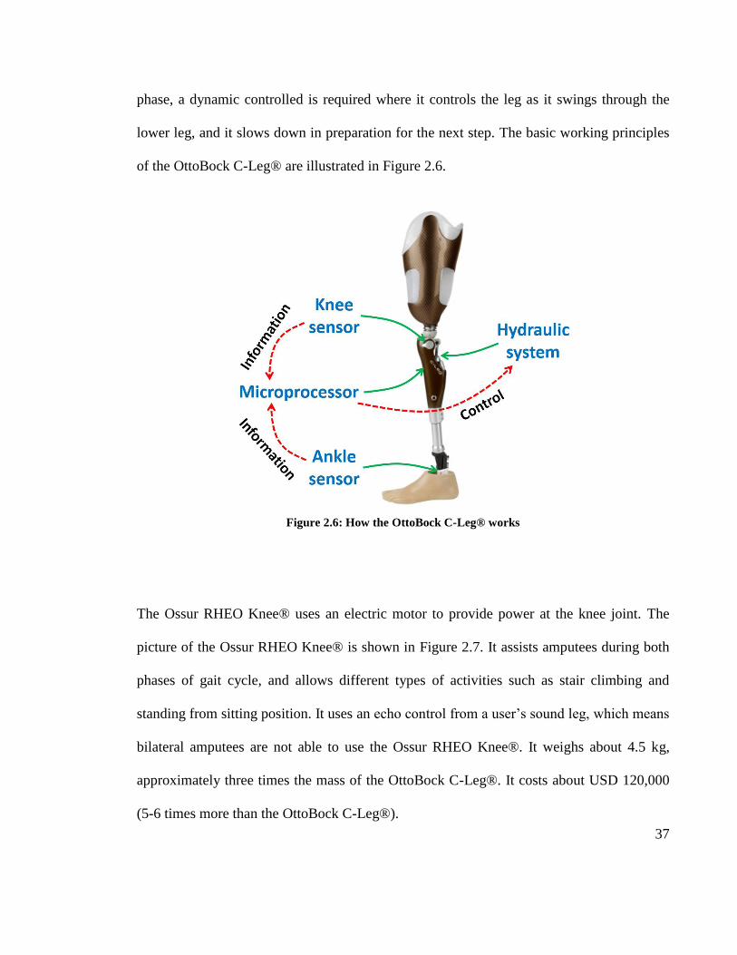
phase, a dynamic controlled is required where it controls the leg as it swings through the
lower leg, and it slows down in preparation for the next step. The basic working principles
of the OttoBock C-Leg® are illustrated in Figure 2.6.
Figure 2.6: How the OttoBock C-Leg® works
The Ossur RHEO Knee® uses an electric motor to provide power at the knee joint. The
picture of the Ossur RHEO Knee® is shown in Figure 2.7. It assists amputees during both
phases of gait cycle, and allows different types of activities such as stair climbing and
standing from sitting position. It uses an echo control from a user’s sound leg, which means
bilateral amputees are not able to use the Ossur RHEO Knee®. It weighs about 4.5 kg,
approximately three times the mass of the OttoBock C-Leg®. It costs about USD 120,000
(5-6 times more than the OttoBock C-Leg®).

38
Figure 2.7: The Ossur RHEO Knee®
As discussed above, the designs of the prosthetic knees in the market varies greatly
amongst them. The classification and comparison of input method, control, and actuation
for currently available motor-actuated prosthetic knees are shown in Table 2.2.
Table 2.2: The classification and comparion of input method, control, and actuation for some of the
prosthetic knees (Reproduced from Martin, 2010)

39
Table 2.2, continued

40
Chapter 3. METHODOLOGY
3.1. Introduction
This thesis project was completed in one semester. The flow diagram in Figure 3.1 shows
the stages to be taken into consideration before this project is completed.
Figure 3.1: Flow diagram for the thesis project
41
3.2. Observation, Research, and Collecting Information
Getting enough information is crucial to ensure the smoothness of this project. The first
step was taken by searching the information related to prosthetic knees from different
sources such as journals and books. Several studies of prosthetic knees were observed and
compared. At the same time, a few commercially successful microprocessor prosthetic
knees were studied.
3.2.1. First Prototype Analysis
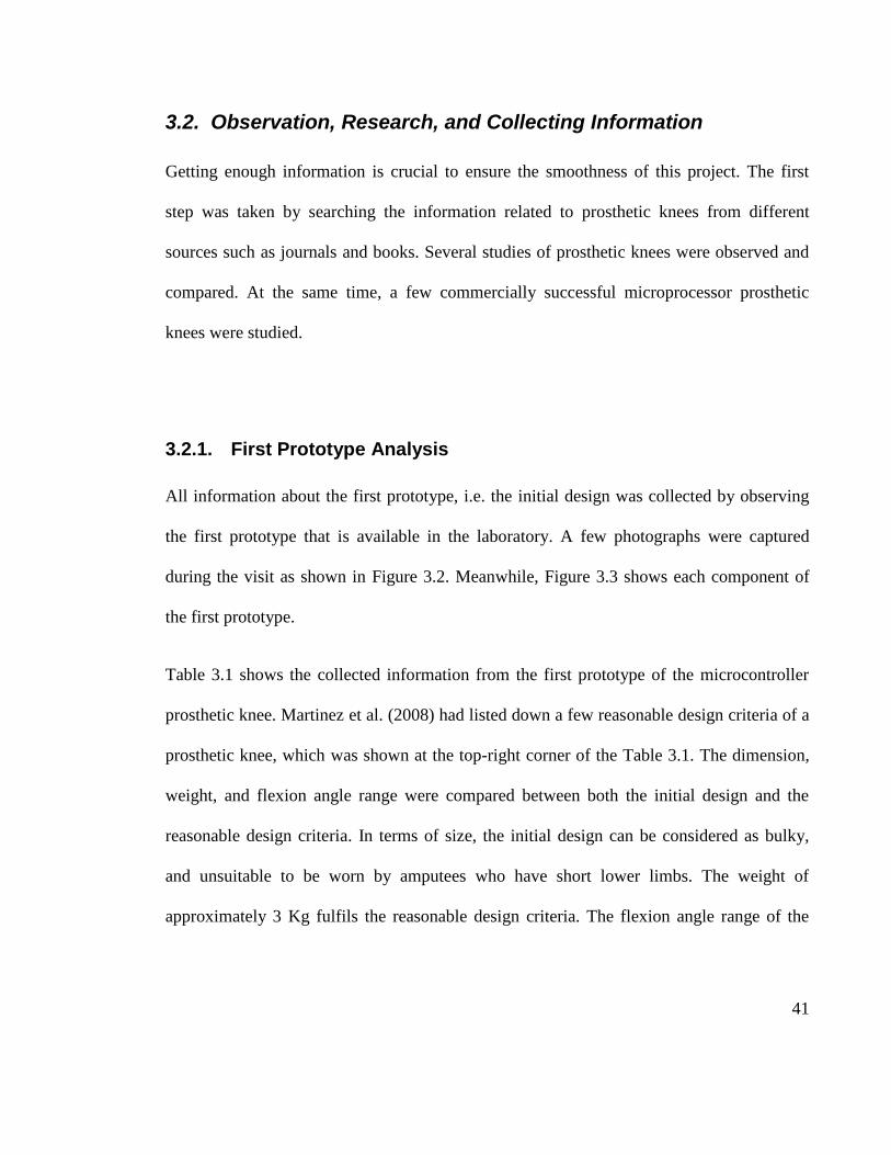
All information about the first prototype, i.e. the initial design was collected by observing
the first prototype that is available in the laboratory. A few photographs were captured
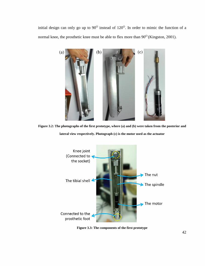
during the visit as shown in Figure 3.2. Meanwhile, Figure 3.3 shows each component of
the first prototype.
Table 3.1 shows the collected information from the first prototype of the microcontroller
prosthetic knee. Martinez et al. (2008) had listed down a few reasonable design criteria of a
prosthetic knee, which was shown at the top-right corner of the Table 3.1. The dimension,
weight, and flexion angle range were compared between both the initial design and the
reasonable design criteria. In terms of size, the initial design can be considered as bulky,
and unsuitable to be worn by amputees who have short lower limbs. The weight of
approximately 3 Kg fulfils the reasonable design criteria. The flexion angle range of the
42
initial design can only go up to 90O instead of 120O. In order to mimic the function of a
normal knee, the prosthetic knee must be able to flex more than 90O (Kingston, 2001).
Figure 3.2: The photographs of the first prototype, where (a) and (b) were taken from the posterior and
lateral view respectively. Photograph (c) is the motor used as the actuator
Figure 3.3: The components of the first prototype

43
Table 3.1: Analysis of the first prototype.
Reasonable design criteria of a
prosthetic knee.
(Adapted from Martinez et al., 2008).
Dimension Length: 450 mm
Width: 110 mm
Length: 330 mm
Width: 70 mm
Weight ~ 3 Kg 3 Kg
Flexion angle range 0O - 90O 0O - 120O
Material used Aluminium 6061
Knee joint type Simple, hinge based,
one degree of freedom
Time taken to flex
the knee up to 90O ~ 40 seconds (2.25 deg/s)
Gearing structure No gearing structure.
Aesthetic value A very long cylinder object (looks like a bazooka)
Motor used
Brand Maxon spindle drive
Model of the spindle
Spindle drive GP 32 S,
Ø 32 mm,
Metric spindle
Length of the spindle 200 mm
Spindle pitch to pitch
value 1 mm
Max output speed Theoretical: 25000 RPM
Practical: 16700 RPM
Gear ratio 492:1
Speed of the spindle Theoretical: 50.8 RPM
Practical: 33.9 RPM
Maximum feed velocity Practical: 0.5 mm/s
Note: OK NOT OK
44
The initial design was fabricated using aluminium 6061 thus it is lightweight. The knee
joint consists of a simple, hinged based structure. It allows a movement of one degree of
freedom. The most obvious issue of the initial design is the time taken for the knee to flex.
It takes approximately 40 seconds to flex the knee from 0 to 90O, which is too slow and
unacceptable for practical application. The initial design contains no gearing structure. The
long cylindrical shell of the initial design does not look appealing and a new cover to
increase the aesthetic value must be done.
A Maxon spindle drive motor was purchased to be used in this project. The model of the
spindle is Spindle drive GP 32 S (metric spindle) with a diameter of 32 mm. It has a length
of 200 mm, and a pitch to pitch value of 1 mm. For the actuated motor, the maximum
output speed is 25000 RPM, which is quite fast. However, due to some limitations with the
power supply in the laboratory, the maximum speed reaches up to 16700 RPM only. A gear
ratio of 492:1 makes the actuated motor to have high torque, so that it has enough strength
to flex the prosthetic knee. After assembling the actuated motor to the initial design, it
proved that the actuated motor has enough strength to flex the prosthetic knee up to 90 .
But, in a very slow motion. The maximum feed velocity of 0.5 mm/s was measured
manually using a stopwatch and a ruler. This value contributes to the longer time for the
prosthetic knee to flex.

45
3.3. Identifying the Problem Statement
The initial design was carefully examined. After the information was gathered, the pros and
cons of the initial design were determined. The major concern is about the functionality and
usability of the initial design. The prosthetic knee of the initial design flexes in a very slow
speed. The flexion angle range does not mimic a normal, healthy knee. The initial design is
not user-friendly due to its size. It also has low aesthetic value.
3.4. Identification of Objectives
After all the problems were determined, the method to solve them must be found. This
project will try to solve those problems which are currently found in the initial design of the
prosthetic knee. The objectives must be listed down to ensure that this project ends with
success. The objectives serve as targets or guidelines to achieve for the final product and
the successful implementation of the final design.
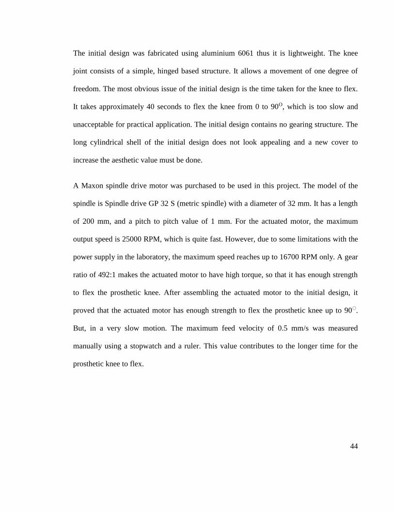
3.5. Identification of the Design Criteria
After all problems with the initial design were defined, the problems must be translated into
design criteria. These design criteria are the explicit goals in this project that must be
achieved in order to be successful. The design criteria of this project are listed in Figure
3.4.
46
DC 1: Range of motion
i. The prosthetic knee must be able to flex from 0 to 120 degrees.
DC 2: Speed
i. The time taken to flex the prosthetic knee from 0 to 120 degrees must be within 2
seconds. It means the knee flexion velocity is at 60 deg/sec.
DC 3: Dimension
i. The prosthetic knee must be small enough to be used by Malaysian amputees.
ii. The length and the width of the prosthetic knee should be around 250 mm and 70
mm respectively.
DC 4: Weight
i. The prosthetic knee must be light. The materials used should be picked carefully
to avoid excessive weight.
ii. The prosthetic knee should have a weight of maximum 3 Kg.
DC 5: Strength
i. The prosthetic knee should be able to withstand a load of 800 N.
ii. The amputees weighted of 80 Kg and less should be able to wear the prosthetic
knee.
DC 6: Cost and quality
i. The materials used must be selected based on their cost and quality.
ii. The aesthetic value must be taken into account during the design process.
Figure 3.4: The design criteria for the project
3.5.1. Range of Motion
The maximum angle of a normal knee can bend is 140O as illustrated in Figure 3.5 (a). In
most activities, the knee is not fully bent up to 140O. Instead, the flexion angle range
required to accomplish most activities is range only from 0 to 120O as illustrated in Figure

47
3.5 (b) (Kingston, 2001). The first design criteria were set based on this information. By
wearing the prosthetic knee, it is expected that the amputees will not be able to achieve the
maximum flexion angle of the normal knee. But, it is anticipated that at least the amputees
can be able to perform most of their daily activities by allowing the prosthetic knee to flex
up to 120O.
Figure 3.5: Flexion of the knee, (a) The maximum angle of the knee can bend, (b) The angle required
for most activities (Adapted from Kingston, 2001)
3.5.2. Speed
Mobility is crucial for human to ensure that they can move from one place to another. The
most common activity of human to move is by walking. Figure 3.6 shows graphs of knee
flexion angle and knee flexion velocity from a study of 8 normal subjects by Fox and Delp
over a range of walking speeds. The study shows that the mean value of the knee flexion
velocity in ‘free’ category is at 300 deg/sec. Meanwhile, the mean value in ‘very slow’

48
category is at 180 deg/sec (Fox & Delp, 2010). The second design criteria was set after
considering two things:
i) The walking speed for amputees is slower compared to normal persons (Pitkin,
2010). In that sense, this project aims to have the knee flexion velocity of the
prosthetic knee at 60 deg/sec.
ii) Despite the value of 60 deg/sec is still far to mimic the normal knee flexion
velocity, it is considered as a big improvement if compared to the knee flexion
velocity of 2.25 deg/sec from the initial design of the prosthetic knee.
Figure 3.6: The graphs of knee flexion angle and knee flexion velocity in a study of 8 normal subjects
(Adapted from Fox & Delp, 2010)

49
3.5.3. Dimension
The dimension of the prosthetic knee must be small enough to be used by local Malaysian
amputees. Table 3.2 shows the mean height and body weight in a national sample of
Malaysian adults (Lim & Ding, 2000). The average height of women in ‘All’ category was
selected to estimate the minimum length of shank of local Malaysian amputees. From the
body anthropometry diagram in Figure 3.7, the shank length that was expressed as a ratio of
body height is 0.204.
Table 3.2 - The mean height and body weight in a national sample of Malaysian adults (Adapted from
Lim & Ding, 2000)
All Malay Chinese Indian
Other
indigenous
M W M W M W M W M W
Height
(cm) 165.0 154.0 164.7 153.3 166.9 156.5 167.6 154.7 161.6 150.8
Weight
(Kg) 61.8 54.7 61.6 55.0 64.6 55.0 64.9 56.5 58.3 51.5
Note: M – Men, W – Women
Figure 3.7: The shank length expressed as a ratio of body height (Adapter from Dillis & Contini, 1966)

50
From the information presented, the estimated minimum length of the shank of local
Malaysian amputees is 378.8 mm as illustrated in Figure 3.8. The prosthetic knee unit is
expected to have a length of two thirds of the estimated minimum length of the shank. In
that case, the expected length of the prosthetic knee unit is approximately 250 mm. The
width of the prosthetic knee of 70 mm follows the reasonable design criteria by Martinez et
al. (2008).
Figure 3.8: The estimated length of the shank, and the estimated length of the prosthetic knee unit
3.5.4. Weight, Strength, Cost and Quality
The weight, strength, cost, and quality relate to materials selection as illustrated in Figure
3.9. The materials must be selected carefully in order to fulfil all four criteria. The weight
of 3 Kg was selected based on the reasonable design criteria of a prosthetic knee by
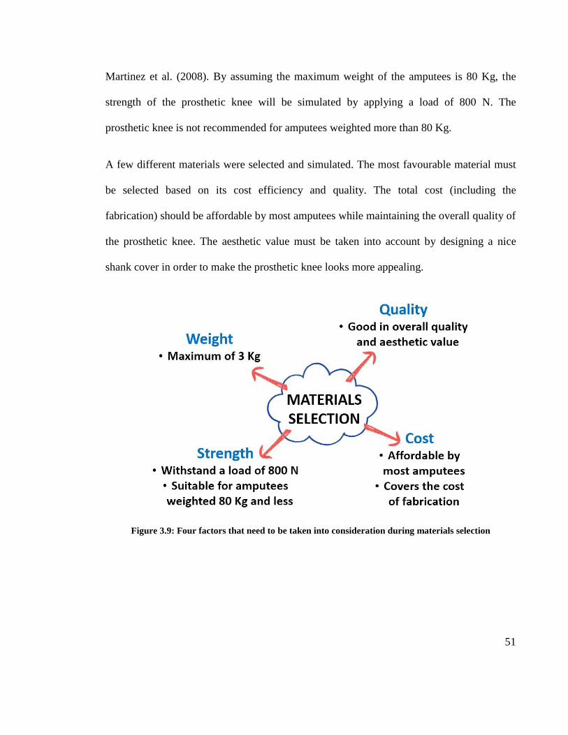
51
Martinez et al. (2008). By assuming the maximum weight of the amputees is 80 Kg, the
strength of the prosthetic knee will be simulated by applying a load of 800 N. The
prosthetic knee is not recommended for amputees weighted more than 80 Kg.
A few different materials were selected and simulated. The most favourable material must
be selected based on its cost efficiency and quality. The total cost (including the
fabrication) should be affordable by most amputees while maintaining the overall quality of
the prosthetic knee. The aesthetic value must be taken into account by designing a nice
shank cover in order to make the prosthetic knee looks more appealing.
Figure 3.9: Four factors that need to be taken into consideration during materials selection

52
3.6. Rough idea for the design
After all the information was analysed and the market products were surveyed, the rough
idea for the design was formulated. The design criteria were used as guidelines during the
design process. The rough idea was drawn and presented to supervisor to obtain advice in
terms of mechanical properties and the strength of the design. Two-way communication
was practiced with the supervisor for several brainstorming sessions. During the sessions,
no idea was judged or discarded. All ideas were recorded for use in the next step of the
process.
3.6.1. Rough idea 1
A gearing structure is introduced in the first rough idea to increase the knee flexion angle
and knee flexion velocity. An internal gearing structure with a ratio of 10 is used. The
pinion and the annular gear are modified to reduce the size as illustrated in Figure 3.10.
With a smaller size, they can easily fit in the prosthetic knee.
Figure 3.10 : The modified pinion and annular gear of an internal gearing structure
(Adapted from Wikipedia)
53
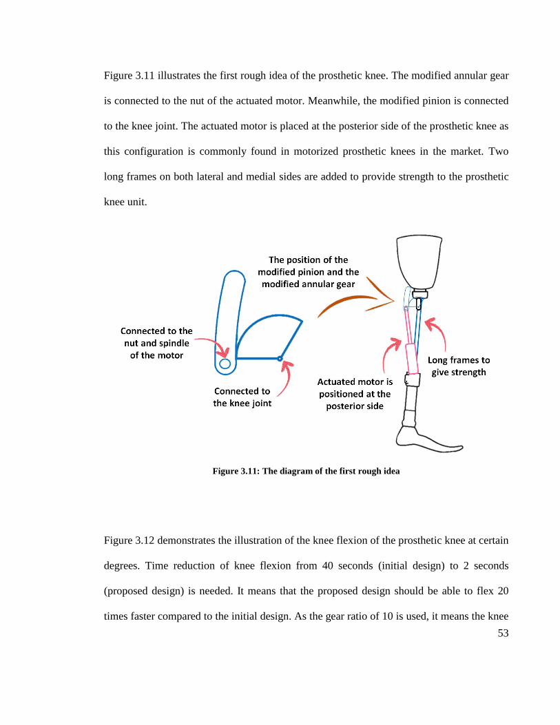
Figure 3.11 illustrates the first rough idea of the prosthetic knee. The modified annular gear
is connected to the nut of the actuated motor. Meanwhile, the modified pinion is connected
to the knee joint. The actuated motor is placed at the posterior side of the prosthetic knee as
this configuration is commonly found in motorized prosthetic knees in the market. Two
long frames on both lateral and medial sides are added to provide strength to the prosthetic
knee unit.
Figure 3.11: The diagram of the first rough idea
Figure 3.12 demonstrates the illustration of the knee flexion of the prosthetic knee at certain
degrees. Time reduction of knee flexion from 40 seconds (initial design) to 2 seconds
(proposed design) is needed. It means that the proposed design should be able to flex 20
times faster compared to the initial design. As the gear ratio of 10 is used, it means the knee

54
can already flex 10 times faster. But, this is not fast enough. To make the proposed design
20 times faster, the original spindle has to be replaced with a new spindle with a pitch to
pitch value of 2 mm as illustrated in Figure 3.13.
Figure 3.12: The illustration of the knee flexion at certain degrees
Figure 3.13: The new proposed spindle with 2 mm pitch to pitch value
55
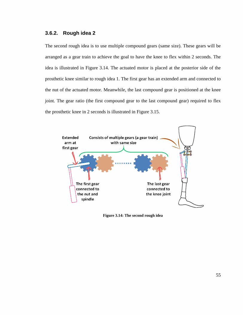
3.6.2. Rough idea 2
The second rough idea is to use multiple compound gears (same size). These gears will be
arranged as a gear train to achieve the goal to have the knee to flex within 2 seconds. The
idea is illustrated in Figure 3.14. The actuated motor is placed at the posterior side of the
prosthetic knee similar to rough idea 1. The first gear has an extended arm and connected to
the nut of the actuated motor. Meanwhile, the last compound gear is positioned at the knee
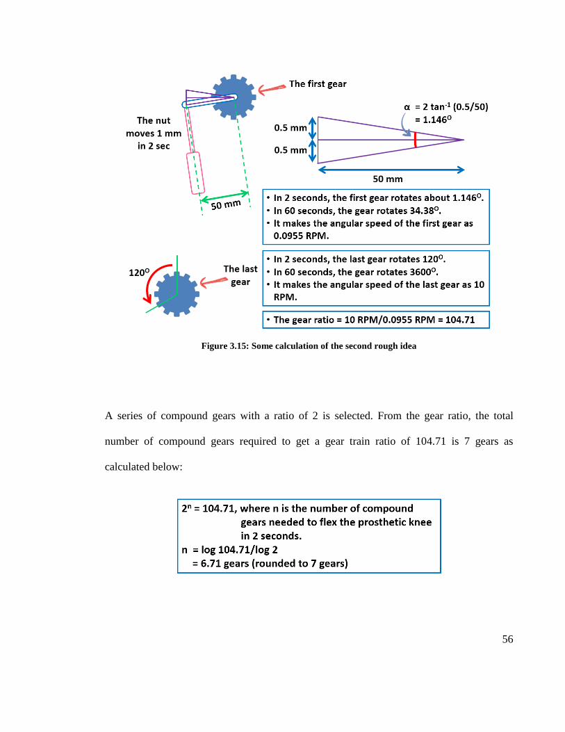
joint. The gear ratio (the first compound gear to the last compound gear) required to flex
the prosthetic knee in 2 seconds is illustrated in Figure 3.15.
Figure 3.14: The second rough idea
56
Figure 3.15: Some calculation of the second rough idea
A series of compound gears with a ratio of 2 is selected. From the gear ratio, the total
number of compound gears required to get a gear train ratio of 104.71 is 7 gears as
calculated below:

57
The arrangement of these 7 compounds gears is illustrated in Figure 3.16. These compound
gears are connected by 6 idler gears in order to have a complete gear train structure. This
idea is theoretically acceptable, but in practice, it is difficult to tell whether this idea is
going to work or not.
Figure 3.16: (a) The compound gear with ratio of 2, (b) The idler gear, (c) The gear train (2D view), and
(d) The gear train (3D view)
3.6.3. Rough idea 3
The rough idea 3 focuses on weight concentration. The idea is to concentrate the weight as
near as possible to the knee joint to reduce the required moment to flex the knee joint as
illustrated in Figure 3.17. If the weight is concentrated at the inferior side (Figure 3.17 (a)),
the distance between the knee joint and the center of concentrated weight is farther
compared to the concentrated weight at the superior side (Figure 3.17 (b)). It is indirectly

58
saying that the concentrated weight at the superior side is recommended in order to have a
lower acted moment at the knee joint and to consume less energy to flex the knee. The
actuated motor will be positioned upside down to allow more concentrated weight near to
the knee joint as illustrated in Figure 3.18. A frame is needed to hold the motor in place.
Figure 3.17: The weight concentration at (a) inferior side, and (b) superior side of the prosthetic knee
Figure 3.18 – The illustration of weight of the motor and the spindle

59
In order to allow the prosthetic knee to flex up to 120O, a plastic chain will be used due its
flexibility. The example of the plastic chain is shown in Figure 3.19. The third rough idea is
illustrated in Figure 3.20. One end of the plastic chain is connected to the socket body, and
the other end is connected to the motor frame. A pivot is positioned at the anterior side to
create enough distance to create a moment at the knee joint.
Figure 3.19: Example of plastic chain (Reproduced from Tinycontrols, 2012)
Figure 3.20: The configuration of the third rough idea

60
The illustration of the knee flexion at certain degrees is shown in Figure 3.21. As the
weight is concentrated at the superior side, it is expected that the knee joint can be able to
flex faster than the initial design.
Figure 3.21: The illustration of knee flexion of the rough idea 3 at certain degrees
3.7. Finalize and Modelling of the Design
After the rough design stage was successfully went through, the proposed design must be
finalized. The final design was obtained after considering advice and consultations from the
supervisor and a few other mechanical engineers. A few discussions in terms of mechanical
structure, strength, and ease of fabrication were carried out.
61
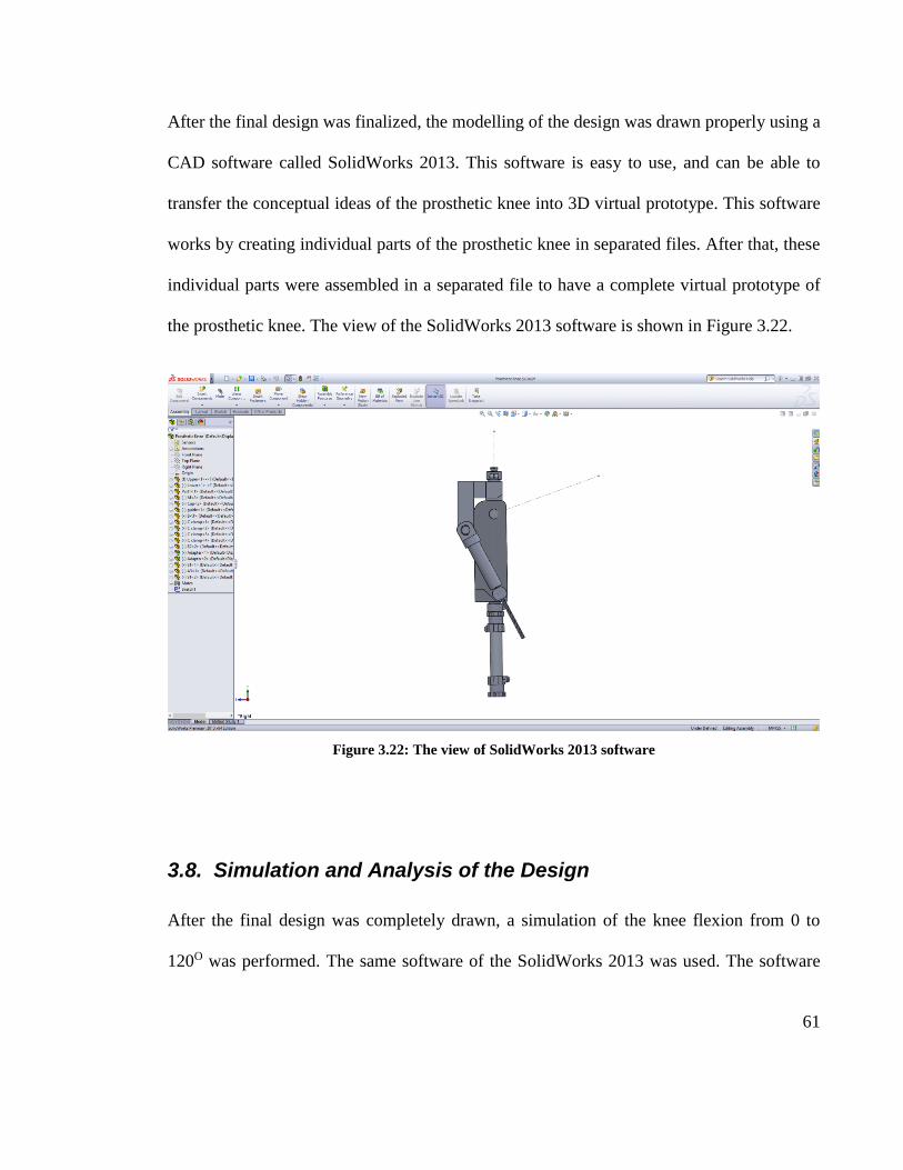
After the final design was finalized, the modelling of the design was drawn properly using a
CAD software called SolidWorks 2013. This software is easy to use, and can be able to
transfer the conceptual ideas of the prosthetic knee into 3D virtual prototype. This software
works by creating individual parts of the prosthetic knee in separated files. After that, these
individual parts were assembled in a separated file to have a complete virtual prototype of
the prosthetic knee. The view of the SolidWorks 2013 software is shown in Figure 3.22.
Figure 3.22: The view of SolidWorks 2013 software
3.8. Simulation and Analysis of the Design
After the final design was completely drawn, a simulation of the knee flexion from 0 to
120O was performed. The same software of the SolidWorks 2013 was used. The software

62
provides simulation tools to animate the movement of the prosthetic knee. It helps to test
the design and to make any changes if required. The time spent for the prosthetic knee to
flex was determined from the animation. The software provides a tool called ‘Interference
detection’. The tool identified any interferences between components of the prosthetic
knee. It helped to evaluate and examine those interferences. By detecting these
interferences, the final design was slightly changed (in terms of dimension and shape) in
order to allow smooth movement of the prosthetic knee.
Another simulation was performed using Finite Element Analysis (FEA). The FEA is a
simulation in terms of mathematical modelling by creating a situation to predict the
outcome. In this project, the simulation was performed by creating a situation where an
amputee with a weight of 80 Kg uses the prosthetic knee while lifting up his normal leg as
illustrated in Figure 3.23. The selected situation is where the prosthetic knee experiences
the highest load of body weight during walking.
Figure 3.23: The situation of an amputee uses the prosthetic knee while lifting up his normal leg

63
The FEA was performed only on the prosthetic knee unit. A load of 800 N was applied at
the most superior of the prosthetic knee unit as illustrated in Figure 3.24. Meanwhile, the
most inferior part was set to be fixed. The results of the FEA were presented based on these
two analyses. The analyses are displacements and stresses. The results were evaluated
carefully.
Figure 3.24: The application of a load of 800 N on the prosthetic knee unit

64
Chapter 4. RESULTS
4.1. The Design
4.1.1. Overview
The complete structure of the prosthetic leg of this project is illustrated in Figure 4.1. The
socket, the pylon, and the prosthetic foot are commercial products from the market. This
project focuses only in designing the prosthetic knee unit for transfemoral amputees. The
prosthetic knee covers the areas of the thigh, and the shank. Figure 4.2 illustrates that
29.7% of total length of the prosthetic knee falls in the thigh area, and another 70.3% falls
in the shank area. It means that the knee joint is located approximately 30% from the
topmost of the prosthetic knee.
Figure 4.1: The complete structure of the prosthetic leg for this project

65
Figure 4.2: The percentage of the prosthetic knee at thigh and shank
Figure 4.3 shows the assembled and the exploded view of the prosthetic knee. All
components of the prosthetic knee are labelled and shown in the figure. Each component
has their own functions and characteristics.
Figure 4.3: The assembled view (a) and the exploded view (b) of the prosthetic knee unit
66
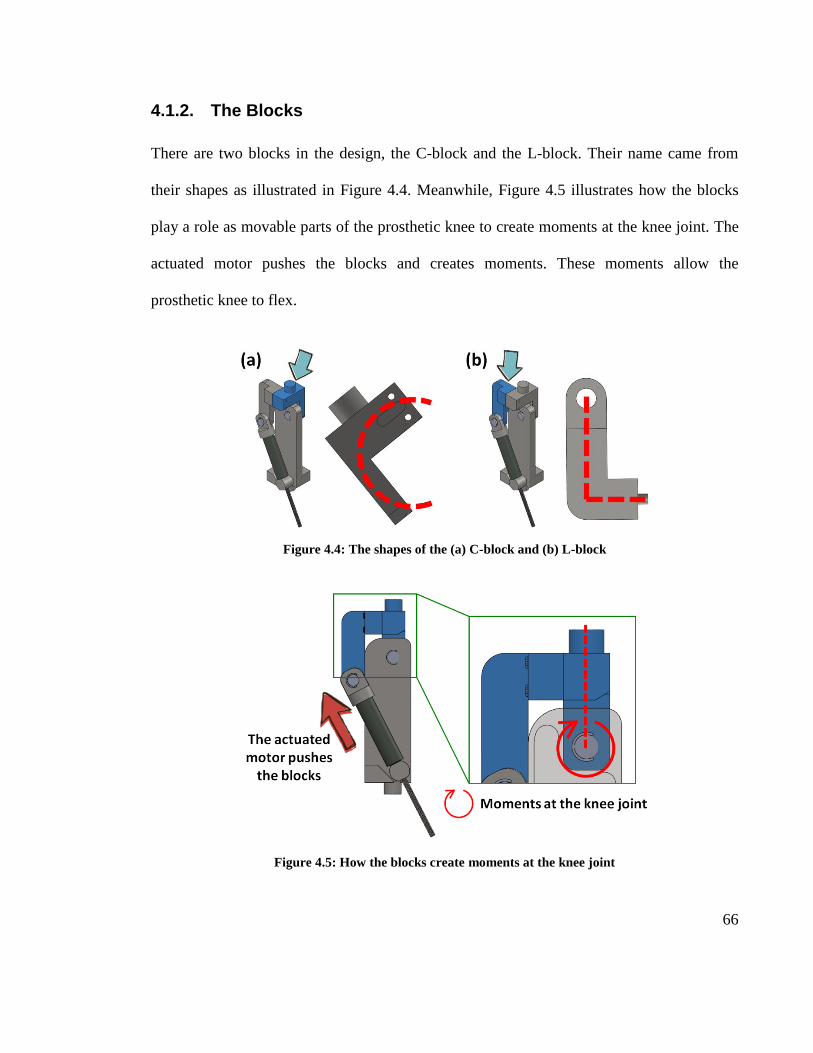
4.1.2. The Blocks
There are two blocks in the design, the C-block and the L-block. Their name came from
their shapes as illustrated in Figure 4.4. Meanwhile, Figure 4.5 illustrates how the blocks
play a role as movable parts of the prosthetic knee to create moments at the knee joint. The
actuated motor pushes the blocks and creates moments. These moments allow the
prosthetic knee to flex.
Figure 4.4: The shapes of the (a) C-block and (b) L-block
Figure 4.5: How the blocks create moments at the knee joint

67
These two blocks are attached by two screws as illustrated in Figure 4.6. The screws hold
these two blocks together where they can be considered as one rigid body. They will be
built separately for ease of fabrication. A male pyramid adapter (commercial product) is
placed on top of the C-block. The male pyramid adapter will be connected to the socket.
The CS connector connects the C-block to the spine. The L-block is connected to the motor
cap using the LC connector.
Figure 4.6: The connections of the blocks
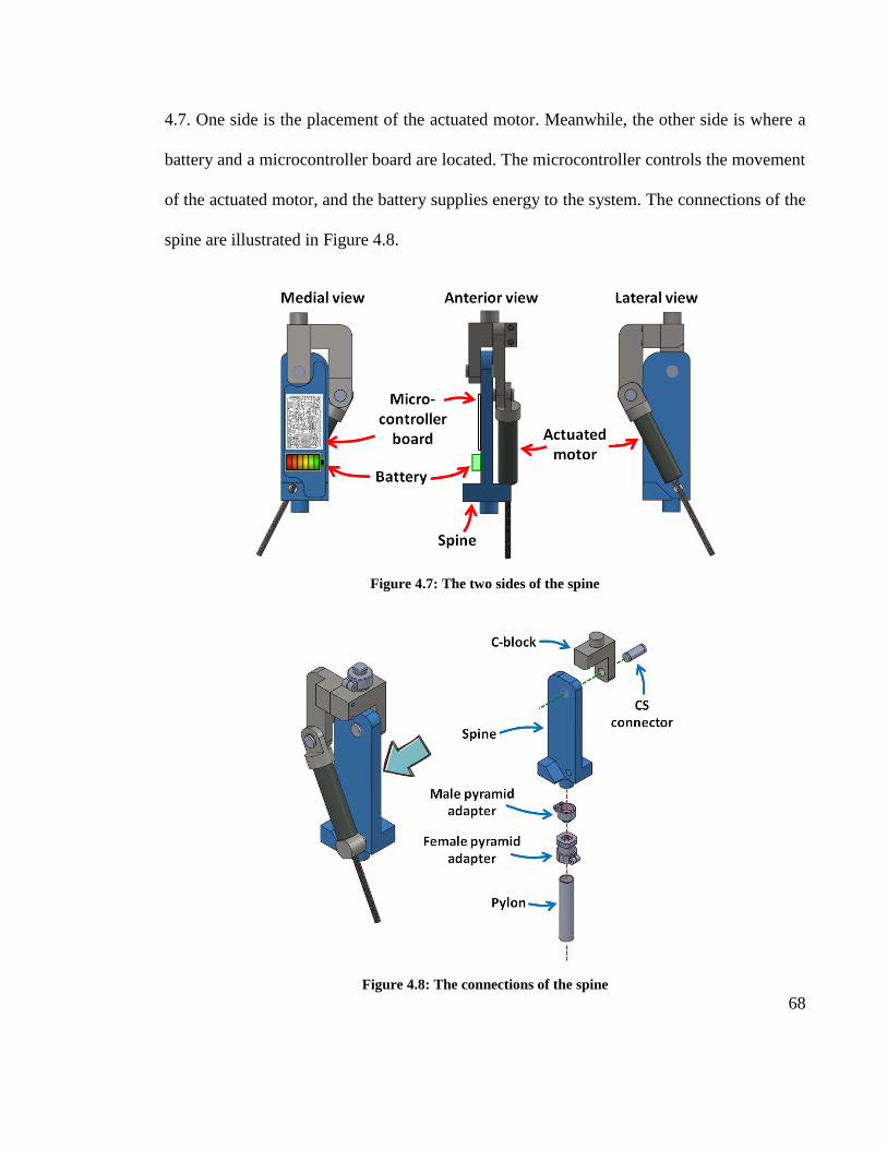
4.1.3. The Spine
The spine acts as a backbone of the prosthetic knee where it supports most of the applied
load on the prosthetic knee during any kind of activities. The spine is the biggest
component in the prosthetic knee. There are two sides of the spine as illustrated in Figure
68
4.7. One side is the placement of the actuated motor. Meanwhile, the other side is where a
battery and a microcontroller board are located. The microcontroller controls the movement
of the actuated motor, and the battery supplies energy to the system. The connections of the
spine are illustrated in Figure 4.8.
Figure 4.7: The two sides of the spine
Figure 4.8: The connections of the spine

69
4.1.4. The Motor Cap and the O-nut
The motor cap and the O-nut hold the actuated motor in place. They work together to rotate
the knee joint as illustrated in Figure 4.9. First, the microcontroller sends a signal to
activate the actuated motor. Then, once the actuated motor is activated, the spindle rotates
and creates a gap between the motor and the O-nut. The gap allows the motor to move
upward. After that, the motor cap, which connected to the actuated motor pushes the blocks
(both C-block and L-block) posteriorly. Finally, the knee joint rotates and allow the
prosthetic knee to flex. The flexion of the prosthetic knee for certain degrees is illustrated in
Figure 4.10.
Figure 4.9: The role of the motor cap and the O-nut in rotating the knee joint

70
Figure 4.10: The flexion of the prosthetic knee at certain degrees
4.1.5. The Connectors
There are two main connectors in the design, the CS connector and the LC connector. The
CS connector connects the C-block to the spine. Meanwhile, the LC connector connects the
L-block to the motor cap. Two C-clamps are used to clamp each connector on both sides.
Figure 4.11 illustrates how the CS connector is clamped by the C-clamps. Ease of
maintenance can be achieved by using this type of clamping where the design can be easily
assembled and disassembled. A lubricant or oil must be applied to the connectors to allow
the prosthetic knee to move smoothly. This can be done by taking out the C-clamp and
disassemble the components. The lubricant will be applied once for 3-4 months depending
on how frequent the prosthetic knee is used.

71
Figure 4.11: The orientation of the CS connector and the C-clamps
4.1.6. The Shank Cover
The shank cover was designed mainly for a cosmetic purpose. The shape of the shank cover
is inspired by the shape of a normal shank as shown in Figure 4.12. It allows the prosthetic
knee to look more appealing to the eyes. It also acts as a protection of the prosthetic knee
from dust, dirt and damage. The shank cover consists of two symmetrical parts (A and B)
as shown in Figure 4.13. The both parts are tightened by screws. Instead of old moulding
method, the shank cover will be built by using 3D printing technology. A 3D printer can
print out the shank cover in different sizes (depends on the size of amputees), and colors
(depends on the amputees’ preferences). The material of the shank cover is a type of plastic
known as acrylonitrile butadiene styrene (ABS). The ABS was picked because it is a
dominant material in the 3D printing technology.

72
Figure 4.12: The different views of the shank cover
Figure 4.13: The symmetrical parts of the shank cover

73
4.2. The Simulation and Analysis
4.2.1. Finite Element Analysis
Three types of materials are nominated in this project. They are Aluminium Alloy 6061,
AISI 316 Stainless Steel, and AISI 4130 Steel. In the end of this project, only one material
was selected. The simulations using FEA were conducted to all materials. Two types of
analyses were performed. They were the stress Von Mises analysis and the displacement
analysis as shown in Figure 4.14 and Figure 4.15. The summary of the static stress analysis
and the displacement analysis are tabulated in Table 4.1.
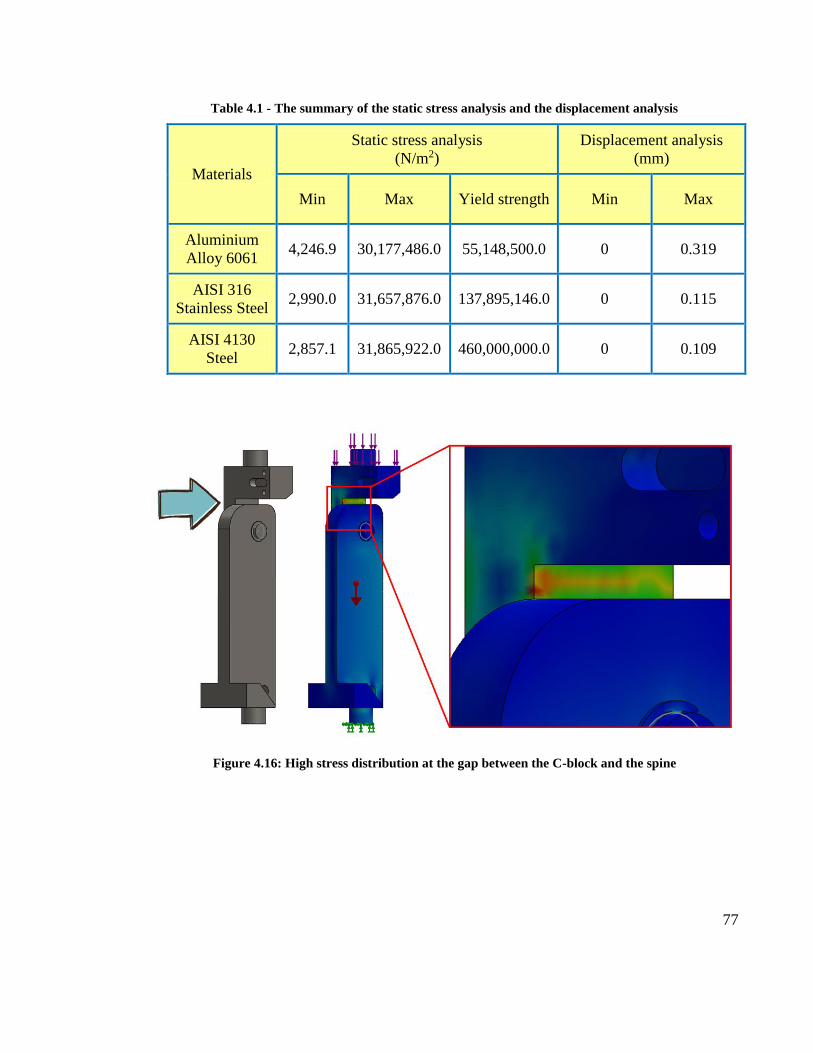
4.2.1.1. The Stress Von Mises Analysis
The stress distribution experienced by the prosthetic knee unit ranged from 4,246.9 N/m2 to
30,177,486.0 N/m2 for Aluminium Alloy 6061, 2,990.0 N/m2 to 31,657,876.0 N/m2 for AISI
316 Stainless Steel, and 2,857.1 N/m2 to 31,865,922 N/m2 for AISI 4130 Steel. The color
key refers to the different stress value distributed across the prosthetic knee unit. Low stress
distribution is highlighted in blue and light blue, which covered almost every part of the
prosthetic knee unit. High stress distribution (highlighted in red and yellow) is present in
the gap between the C-block and the spine as shown in Figure 4.16. Failure might happen
to that part if excessive load is applied to the prosthetic knee unit. From the static stress
analysis, the AISI 4130 is the best material to be selected because there is a big gap
between the values of the maximum stress (31,865,922.0 N/m2) to the value of yield

74
strength (460,000,000.0 N/m2) of that material. The yield strength is the value of stress of
the material can withstand without any permanent deformation.
4.2.1.2. The Displacement Analysis
From Figure 4.15, the color key refers to the different displacement value distributed across
the prosthetic knee unit. As the bottom of the prosthetic knee unit is set to be fixed, there is
zero displacement on that region. The displacement is high in red/orange color regions
which distributed at top regions for all types of materials. The highest displacements
recorded are 0.319 mm for Aluminium Alloy 6016. Then it followed by 0.115 mm for AISI
316 Stainless Steel, and 0.109 mm for AISI 4130 Steel. The displacements for both AISI
316 Stainless Steel and AISI 4130 Steel are very small and preferable. Although the
Aluminium Alloy 6016 recorded the highest displacement of 0.319 mm, it is still
acceptable because the value is still very small and almost negligible.

75
Figure 4.14: The stress Von Mises analysis for all three materials

76
Figure 4.15: The displacement analysis of all three materials
77
Table 4.1 - The summary of the static stress analysis and the displacement analysis
Materials
Static stress analysis
(N/m2)
Displacement analysis
(mm)
Min Max Yield strength Min Max
Aluminium
Alloy 6061 4,246.9 30,177,486.0 55,148,500.0 0 0.319
AISI 316
Stainless Steel 2,990.0 31,657,876.0 137,895,146.0 0 0.115
AISI 4130
Steel 2,857.1 31,865,922.0 460,000,000.0 0 0.109
Figure 4.16: High stress distribution at the gap between the C-block and the spine

78
4.2.2. Knee Flexion Animation
The SolidWorks 2013 was used to animate the prosthetic knee in order to explain and
simulate its function and assembly. The animation was converted to a video with format of
Audio Video Interleave (AVI). The AVI is a popular container file format used for
watching standard definition video and can be played in almost all video players. To obtain
a high quality video, the resolution of the video was set to 1920x1080 with a frame rate of 7
frames/second. The video is used to present the idea of the design. It also can be used as a
bridge to communicate between technical and nontechnical people. The video shows the
animation of the movement of flexing the prosthetic knee from 0 – 120O. The design was
simulated by considering the specifications of the actuated motor. From the animation
video, the prosthetic knee flexes from 0 – 120O within 6 seconds. Some screenshots of the
animation video are shown in Figure 4.17.
Figure 4.17: Some screenshots of the animation video

79
4.3. Estimated Total Weight and Total Cost for Fabrication
The estimated total weight and the estimated total cost of fabrication are tabulated in Table
4.2. The estimated weights of each part were calculated by the SolidWorks 2013. The
estimated total weight of raw materials is the estimation of the total weight of the parts to
be fabricated as shown in Figure 4.18. Meanwhile, the estimated total weight of the
prosthetic knee is a summation of the estimated total weight of raw materials, the estimated
weight of the shank cover, and the estimated total weight of the available parts as illustrated
in Figure 4.19 and Figure 4.20.
Figure 4.18: The parts to be fabricated

80
Figure 4.19: The formula in estimating the total weight of the prosthetic knee
Figure 4.20: The estimation of weight of the available parts

81
The estimated total weight of raw materials are vary from Aluminium Alloy 6061 to AISI
4130 Steel. The Aluminium Alloy 6061 is the lightest material compared to the other two
materials with weight of 2.02 Kg. The estimated weight of raw materials for both AISI 316
Stainless Steel and AISI 4130 Steel are more or less the same with weight of 5.99 Kg and
5.86 Kg respectively. The spine is the heaviest component among all components in the
prosthetic knee. After assembling all components with available parts and shank cover, the
lightest estimated weight of the prosthetic knee is using Aluminium Alloy 6061 with
weight of 2.87 Kg. By comparing all three materials, the Aluminium Alloy 6016 is the only
material that fulfil the fourth design criteria to have a weight of prosthetic knee less than 3
Kg.
The estimated total cost of raw materials were calculated based on the prices available in
the SolidWorks 2013 database. The price of a Kg of each material were converted from US
Dollar (USD) to Ringgit Malaysia (MYR). The cheapest estimated cost of raw material
goes to the AISI 4130 Steel with a cost of RM 9.84. The fabrication charges of RM 1800 is
the estimated cost from Zecttron Sdn Bhd. It includes the fabrication of all components in
the prosthetic knee. After considering all the simulation results, the Aluminium Alloy 6061
was selected to be used in the design. Although the Aluminium Alloy 6061 fell behind for
the FEA results, its lightweight and cost efficiency made it to be the best material for the
prosthetic knee. The shank cover will be built separately by using a 3D printer. The 3D
printed ABS costs RM2 per gram (3DCipta, 2013).

82
Table 4.2: The estimated weight and cost for different types of materials
Materials Aluminium Alloy
6061
AISI 316
Stainless Steel
AISI 4130
Steel
Parts The estimated weight of each component (Kg)
C-block 0.47 1.40 1.37
L-block 0.38 1.13 1.11
Spine 0.93 2.76 2.70
Motor cap 0.09 0.26 0.25
O-nut 0.08 0.23 0.22
CS connector 0.04 0.12 0.12
LC connector 0.03 0.09 0.09
Estimated total weight of
raw materials 2.02 5.99 5.86
Estimated total weight of
the prosthetic knee 2.87 6.84 6.71
Price of raw materials (RM/Kg)
7.26 11.81 1.68
The estimated cost (RM)
Estimated total cost of
raw materials 14.67 70.74 9.84
Estimated total cost of
fabrication 2114.67 2170.74 2109.84
Notes:
The total cost of fabrication including the estimated fabrication charges of RM 1800
and the cost of the shank cover (RM 2 per gram X 0.15 Kg = RM 300)
The price of the shank cover was referred to the price provided by 3DCipta (2013).
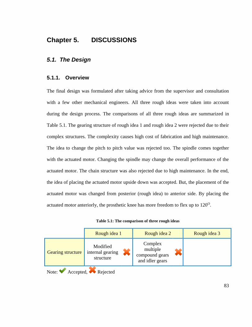
83
Chapter 5. DISCUSSIONS
5.1. The Design
5.1.1. Overview
The final design was formulated after taking advice from the supervisor and consultation
with a few other mechanical engineers. All three rough ideas were taken into account
during the design process. The comparisons of all three rough ideas are summarized in
Table 5.1. The gearing structure of rough idea 1 and rough idea 2 were rejected due to their
complex structures. The complexity causes high cost of fabrication and high maintenance.
The idea to change the pitch to pitch value was rejected too. The spindle comes together
with the actuated motor. Changing the spindle may change the overall performance of the
actuated motor. The chain structure was also rejected due to high maintenance. In the end,
the idea of placing the actuated motor upside down was accepted. But, the placement of the
actuated motor was changed from posterior (rough idea) to anterior side. By placing the
actuated motor anteriorly, the prosthetic knee has more freedom to flex up to 120O.
Table 5.1: The comparison of three rough ideas
Rough idea 1 Rough idea 2 Rough idea 3
Gearing structure
Modified
internal gearing
structure
Complex
multiple
compound gears
and idler gears
Note: Accepted, Rejected

84
Table 5.1, continued
Rough idea 1 Rough idea 2 Rough idea 3
Change the pitch
to pitch value of
the spindle
From 1 mm to
2 mm
Inverted
placement of the
actuated motor
The actuated
motor is place
upside down
Chain structure Using plastic
chain
Note: Accepted, Rejected
5.1.2. The Design Criteria
In general, the final design has fulfilled almost all the design criteria as shown in Table 5.2.
The first design criteria was achieved where the design has a mechanism that allowed the
prosthetic knee to flex from 0 – 120O. From the animation, the time taken for the prosthetic
knee to flex from 0 – 120O is within 6 seconds. This value does not fulfil the second design
criteria, but it is close enough. In terms of dimension, the length from the knee joint to the
most bottom of the prosthetic knee is 236.99 mm as illustrated in Figure 5.1. The width of
the prosthetic knee is around 75 mm instead of 70 mm from the design criteria. Although
there is a difference in the width value, 75 mm is still acceptable and consider as fulfilling
the third design criteria. Since the length of the prosthetic knee is less than 250 mm, it is
expected that Malaysian amputees would be able to use the prosthetic knee.

85
The Aluminium Alloy 6016 was selected as the material to be used to fabricate the
prosthetic knee. The estimated total weight of the prosthetic knee is 2.87 Kg. This fulfil the
fourth design criteria where the design should have a weight of less than 3 Kg. From the
FEA results, the prosthetic knee was proven to be able to withstand a load of 800 N. It
achieved the goal of fifth design criteria. It is expected that an amputee weighted less than
80 Kg could be able to use the prosthetic knee. In term of cost, the total estimated cost to
fabricate the prosthetic knee is RM 2114.67. By selecting the Aluminium Alloy 6061, this
value is still affordable while maintaining the overall performance of the prosthetic knee.
The appearance of the prosthetic knee looks neat and appealing by covering the prosthetic
knee unit with the shank cover. With the affordable cost and the aesthetic value, the sixth
design criteria was achieved too.
Table 5.2: The design criteria checklist
DC 1: Range of motion
The prosthetic knee must be able to flex from 0 to 120 degrees.
DC 2: Speed
The time taken to flex the prosthetic knee from 0 to 120 degrees must be
within 2 seconds.
DC 3: Dimension
The prosthetic knee must be small enough to be used by Malaysian amputees.
The length and the width of the prosthetic knee should be around 250 mm and
70 mm respectively.
DC 4: Weight
The prosthetic knee must be light. The materials used should be picked
carefully to avoid excessive weight.
The prosthetic knee should have a weight of maximum 3 Kg.

86
Table 5.2, continued
DC 5: Strength
The prosthetic knee should be able to withstand a load of 800 N.
The amputees weighted of 80 Kg and less should be able to wear the prosthetic
knee.
DC 6: Cost and quality
The materials used must be selected based on their cost and quality.
The aesthetic value must be taken into account during the design process.
Figure 5.1: The length from the knee joint to the bottom of the prosthetic knee

87
5.2. The Simulation
The simulation process was completed by using the SolidWorks 2013. The simulation was
required to ensure that the product would not fail under real life situation. The simulation of
FEA was performed to both the C-block and the spine only. It is because only these two
components are aligned with the direction of load from the amputee’s body weight as
illustrated in Figure 5.2. The rest of the components are located at the periphery of the
prosthetic knee which is not affected by the load. From the FEA results, it shows that the
prosthetic knee is safe to be used for amputees of weight less than 80 Kg. There is an area
which might fail if excessive load is applied onto it. It is located at the gap between the C-
block and the spine.
Figure 5.2: The load experience by the C-block and the spine

88
5.3. Suggestion for Future Research
Since the second design criteria was not achieved, more work needs to be done to fulfil the
goal of having the knee flexes within 2 seconds from 0 – 120O. To increase the speed while
using the available actuated motor, a gearing structure with a simple design is needed. The
rough ideas of this project introduced complex gearing structures where they are difficult to
maintain and high cost to fabricate. For the future research, a simple gearing structure that
allows low maintenance and low cost to fabricate should be implemented into the prosthetic
knee. Instead of gearing structure, there are a few more things that can be implemented
such as the use of chains, cable, and belts.
The specifications of the actuated motor need to be revised. It is pretty obvious that the
available actuated motor has a very high torque, but low in speed. The actuated motor was
purchased with focusing too much on the torque and overlooked at the speed. For the future
research, the new specifications of the actuated motor should have a balance between the
torque and the speed. This can be done by purchasing a new actuated motor or modifying
the available motor until it achieves the revised specifications.

89
Chapter 6 Conclusion
Prosthetic knee design involves making a replacement of a missing lower limb by
mimicking a normal, healthy knee. The prosthetic knee should be functional, comfortable,
and good in visual appearance. This project is just a small portion of a big study of a
microcontroller prosthetic leg. The study has its own initial design of the prosthetic knee.
There are a few downsides of the initial design of the prosthetic knee that need to be
improved. The major downsides are low in speed to flex the knee, low in aesthetic value,
and bulky. This project targeted to overcome those problems. The design criteria were
listed down as guidelines during the design process. All design criteria were achieved
except one. Three different types of materials were simulated by using FEA technique. In
the end, the Aluminium Alloy 6061 was selected to be the best material (among the three
types of materials) to be used to fabricate the prosthetic knee. It could withstand a load of
800 N without fail. The maximum displacement of the prosthetic knee after applying 800 N
is 0.319 mm. This value is very small and can be ignored. The estimated total weight of the
prosthetic knee is 2.87 Kg. The shank cover made the prosthetic knee to look more
appealing. The fastest time for the proposed design to flex from 0 to 120O was 6 seconds.
The quality of the prosthetic knees in the market is much higher compared with the
proposed prosthetic knee from this project. But, in terms of functionality, both of them are
still similar. The estimated total cost of fabrication of the prosthetic knee is RM 2114.67.
This amount is affordable to be bought by amputees who come from low to medium
income family.

90
References
3DCipta. (2013). 3D printing. Retrieved from http://www.3dcipta.com.my/3d-printing/
Bowker, J. H., & Pritham, C. H. (2004). Atlas of amputations and limb deficiencies:
surgical, prosthetic, and rehabilitation principles. New York: American academy
of orthopaedic surgeons.
Burns, M. T. (2010). Extreme soft tissue care and amputation in an austere environment.
Retrived from http://www.wheelessonline.com/ortho/12787.
Dorland, W. A. N., & Anderson, D. M. (2003). Dorland's illustrated medical dictionary.
Philadelphia: Saunders.
Ephraim, P. L., & Dillingham, T. R. (2003). Epidemiology of limb loss and congenital limb
deficiency: a review of the literature. Arch Phys Med Rehabil, 84(5), 747-761.
Fite, K. (2007). Design and control of an electrically powered knee prosthesis. Paper
presented at the Conference of Rehabilitation robotics, Noordwijk.
Flowers, W. C., & Mann, R. W. (1977). Electrohydraulic knee-torque controller for a
prosthesis simulator. Journal of biomechanical engineering, 99(4), 3-8.
Freedom Innovations. (2014). Plié® 2.0 Microprocessor Knee, Trust Your Instincts.
Retrieved from http://www.freedom-innovations.com/knees/
Hata, N. (2002). Basic research on power limb using gait information of able-side leg.
Paper presented at The 7th International Workshop on Advanced Motion Control.
Kingston, B. (2001). Understanding joint: A practical guide to their structure and function.
United Kingdom: Nelson Thornes Ltd.
Lambrecht, B. G. A. (2008). Design of a hydbrid passive-active prosthesis for above knee
amputees. (Unpublished doctoral dissertation). University of California, Berkeley.
Lambrecht, B. G. A., & Kazerooni, H. (2009). Design of a semi-active knee prosthesis.
Paper presented at the Proceedings of 2009 IEEE International Conference on
Robotics and Automation.
Larsson, L. E., Odenrick, P., Sandlund, B., Weitz, P., & Oberg, P. A. (1980). The phases of
the stride and their interaction in human gait. Scand J Rehabil Med, 12(5), 107-112.

91
Liikavainio, T. (2010). Biomechanics of gait and physical function in patients with knee
osteoarthritis: thigh muscle properties and joint loading assessment (Doctoral
dissertation). Retrived from http://epublications.uef.fi/
Martin, J., Pollock. A., & Hettinger, J. (2010). Microprocessor lower limb prosthetic:
Review of current state of the art. Journal of Prosthetics and Orthotics, 22(3), 183-
193.
Martinez, E. C., Weber, J., Elliot, G., & Herr, H. (2008). Design of an agonist-antagonist
active knee prosthesis. Journal of Biomedical Robotics and Biomechatronics, 11(5),
19-22.
Ossur. (2014). Rheo knee. Retrived from http://www.ossur.com/prosthetic-solutions/bionic-
technology/rheo-knee
OttoBock. (2014). C-Leg above-knee prosthetic leg. Retrieved from
http://www.ottobockus.com/C-Leg
Sapin, E., & Goujon, H. (2008). Functional gait analysis of trans-femoral amputees using
two different single-axis prosthetic knees with hydraulic swing-phase control:
Kinematic and kinetic comparison of two prosthetic knees. Prosthetics and
Orthotics International, 32(2), 201-218.
Sup, F., Bohara, A., & Goldfarb, M. (2008). Design and control of a powered transfemoral
prosthesis. Journal of Robotics Research, 27(2), 263-273.
Sup, F., Varol, H. A., Mitchell, J., Withrow, T. J., & Goldfrab, M. (2009). Self-contained
powered knee and ankle prosthesis: initial evaluation on a transfemoral amputee.
Journal of Rehabilitation Robotics, 15(4), 251-260.
Waters, R. L., & Mulroy, S. (1999). The energy expenditure of normal and pathologic gait.
Gait and posture, 9(3), 201-231.
Waycaster, G. C. (2010). Design of a powered above knee prosthesis using pneumatic
artificial muscles (Master’s thesis). Retrived from http://acumen.lib.ua.edu/

92
APPENDIX A1 – THE MAXON SPINDLE DRIVE CATALOG (FRONT PAGE)

93
APPENDIX A2 – THE SPINDLE DRIVE CATALOG (BASICS)

94
APPENDIX A2 – THE SPINDLE DRIVE CATALOG
(GP 32 S 32 mm, METRIC SPINDLE)