development of low cost inkjet 3d printing for the
TRANSCRIPT

Copyright is owned by the Author of the thesis. Permission is given for a copy to be downloaded by an individual for the purpose of research and private study only. The thesis may not be reproduced elsewhere without the permission of the Author.
Development of Low Cost
Inkjet 3D Printing for the
Automotive Industry
A thesis presented in partial fulfilment of the requirements for a degree of
Master of Engineering in Mechatronics
Massey University, Albany, New Zealand
Blair Dixon
2017

i
Abstract
The aim of this project is to develop a low cost, powder based 3D printer that utilises inkjet
printing technology. The 3D printer uses a standard drop-on-demand inkjet print head to
deposit a binder onto the powder bed one layer at a time to build the desired object.
Existing commercial 3D printers that use inkjet technology are large and expensive. They do
not allow much control to adjust printing parameters, meaning it is difficult to conduct
research with different materials and binders. Due to these factors it is not viable to use one
for research purposes.
The automotive industry uses 3D printing technology heavily throughout the prototyping
process, some manufacturers have even started using the technology to produce functional
parts for production vehicles. Ford Motor Company helped develop 3D printing technology
and brought it to the automotive industry while multiple university’s in America were
researching the technology.
Based off an open source design, the printer developed in this project has been customised
to allow full control over printing parameters. The body of the printer is laser cut from acrylic.
All mechanical components are off the shelf items wherever possible to keep costs down and
allow the print area to be easily scaled. Binder is deposited with an HP C6602A print head
which is filled with regular black printer ink. The ink is deposited onto a bed of 3D Systems
VisiJet PXL Core powder. Custom made parts manufactured in house allow for the print head
to be easily changed to whatever is needed. The print head used is refillable and can therefore
be filled with custom binders.
With the 3D printer developed in house, all aspects can easily be adjusted. Having full control
over printing parameters will allow research to be conducted to develop new 3D printable
powders and binders, or to improve the printing quality of existing powders and binders.

ii
The 3D printer has also been developed so that it is easy to adapt to other features to increase
its capabilities. With the addition of a UV light source, UV curable binders could be
researched; or with the addition of a laser, powder sintering could be researched.

iii
Acknowledgements
I would like to thank all of those who have supported me in any way throughout this project.
Firstly, I would like to thank my family for supporting and helping me strive to be the best I
can be. Without their love and support I would not be where I am today.
Secondly I would like to thank my supervisor Associate Professor Johan Potgieter. His support
and guidance on both an academic level as well as personal has allowed me to successfully
complete this project.
Thirdly I would like to thank the NZ Product Accelerator group for providing financial support,
without which this project could not have been completed.
Lastly I would like to thank the staff of the School of Engineering and Advanced Technology
at Massey University for ideas and guidance throughout this project.

iv
v
Contents
Abstract ....................................................................................................................................... i
Acknowledgements ................................................................................................................... iii
List of Figures ............................................................................................................................ ix
List of Tables ............................................................................................................................. xi
Abbreviations .......................................................................................................................... xiii
Chapter 1. Introduction ......................................................................................................... 1
1.1 Thesis Outline & Contributions ................................................................................... 3
Chapter 2. Literature Review ................................................................................................. 5
2.1 Additive Manufacturing .............................................................................................. 5
2.2 Inkjet Printing Technology .......................................................................................... 7
2.2.1 How an Inkjet Print Head Works.......................................................................... 8
2.3 Inkjet 3D Printers ......................................................................................................... 9
2.3.1 Full Colour Inkjet 3D Printing ............................................................................. 15
2.3.2 Inkjet 3D Printable Materials ............................................................................. 18
2.3.3 Automotive use of Inkjet 3D Printers ................................................................ 19
2.4 Currently Available Low Cost 3D Printers ................................................................. 23
2.4.1 Hobbyist 3D Printers .......................................................................................... 23
2.4.2 Low Cost Powder 3D Printers ............................................................................ 24
2.5 Chapter Summary...................................................................................................... 26
Chapter 3. Mechanical Components ................................................................................... 29
3.1 3D Printer Body ......................................................................................................... 29
3.2 3D Printer Pistons ...................................................................................................... 31

vi
3.3 Motor Sub-assemblies ............................................................................................... 33
3.4 3D Printer Gantry ...................................................................................................... 35
3.5 Chapter Summary...................................................................................................... 37
Chapter 4. Electrical Components ....................................................................................... 39
4.1 Arduino ...................................................................................................................... 39
4.2 Stepper Motor Drivers .............................................................................................. 40
4.3 Stepper Motors ......................................................................................................... 42
4.4 Darlington Arrays ...................................................................................................... 45
4.5 Print head and Carrier ............................................................................................... 45
4.6 Power Supplies .......................................................................................................... 46
4.7 Prototyping Electronics ............................................................................................. 48
4.8 Veroboard Prototyping ............................................................................................. 49
4.9 Printed Circuit Board ................................................................................................. 51
4.10 Chapter Summary...................................................................................................... 54
Chapter 5. 3D Printer Software ........................................................................................... 57
5.1 Graphic User Interface (GUI) ..................................................................................... 57
5.2 Slicing ......................................................................................................................... 58
5.3 Printing ...................................................................................................................... 60
5.4 Arduino Software ...................................................................................................... 61
5.5 Chapter Summary...................................................................................................... 61
Chapter 6. Implementation ................................................................................................. 64
6.1 Testing ....................................................................................................................... 65
6.2 Hardware Adjustments ............................................................................................. 71
6.3 Software Adjustments ............................................................................................... 79
6.4 Chapter Summary...................................................................................................... 82
Chapter 7. Results and Discussion ....................................................................................... 84
vii
7.1 Investigate the current state of 3D printing technology, including currently
available low cost 3D printers and the current state of 3D printing in the Automotive
industry. ................................................................................................................................ 84
7.2 Investigate the applications of inkjet printing technology with 3D printing ............ 85
7.3 Develop a low cost, powder based 3D printer using ink-jet printing technology .... 86
7.4 Design future capability into the printer hardware .................................................. 89
Chapter 8. Conclusion .......................................................................................................... 90
Chapter 9. References ......................................................................................................... 92
Appendix A – Technical Drawings ............................................................................................ 96
Appendix B – PCB Drawings ................................................................................................... 101
Appendix C – Bill of Materials ................................................................................................ 103
Appendix D – Journal Article .................................................................................................. 105

viii
ix
List of Figures
Figure 1 - 3D Systems ProJet 5500X Multi-material 3D printer (Grunewald, 2015) ............... 11
Figure 2 - Example of a part 3D printed in the in-house ProJet 5500X ................................... 11
Figure 3 - ExOne's M-Flex 3D Printer (Maxey, 2014) ............................................................... 12
Figure 4 - ExOne 3D printed sand parts (ExOne, N.D.-a) ......................................................... 13
Figure 5 - Sand part 3D printed in a Voxeljet machine (Hipolite, 2014) .................................. 13
Figure 6 - View of the Voxeljet VXC800 angled print area and conveyor (3ders, 2012) ......... 14
Figure 7 - HP Multi Jet Fusion 3200 3D Printer (Cleary, 2016) ................................................ 15
Figure 8 - FDM colour changing done with an in-house FDM 3D printer: a) red filament full
colour; b) blue filament full colour; c) colour change from red to blue showing
contamination .......................................................................................................................... 16
Figure 9 - 3DSystems ProJet CJP 660Pro full colour 3D printer (3DSystems, N.D.-b) ............. 17
Figure 10 - Sample part 3D printed on the 3D Systems ProJet CJP 660Pro (DesignPoint, N.D.)
.................................................................................................................................................. 17
Figure 11 - Titanium 3D printed exhaust for the Koenigsegg One:1 (Wade, 2015) ................ 20
Figure 12 - Koenigsegg's 3D printed Titanium turbo (Klapman, 2014) ................................... 21
Figure 13 - Norge Ice1 (left) and Ice9 (right) (Krassenstein, 2014).......................................... 25
Figure 14 - Sintratec Kit SLS 3D printer (Goehrke, 2014) ......................................................... 26
Figure 15 - CAD model of the laser cut body ........................................................................... 31
Figure 16 - CAD model of laser cut piston ............................................................................... 32
Figure 17 - X Axis motor assembly ........................................................................................... 34
Figure 18 - Roller motor assembly ........................................................................................... 35
Figure 19 - Gantry assembly .................................................................................................... 36
Figure 20 - Laser cut body fully assembled .............................................................................. 38
Figure 21 - Arduino Mega 2560 Microcontroller (Arduino, N.D.) ........................................... 40
Figure 22 - Stepper Motor Drivers during testing of the first prototype. a) X/Y/Roller motor
Easy Drivers; b) Z motors BigEasyDrivers................................................................................. 42
Figure 23 - Stepper Motor Control Flow Diagram ................................................................... 43
Figure 24 - LM317T voltage regulator circuit .......................................................................... 47
x
Figure 25 – Breadboard prototype of all electrical components ............................................ 48
Figure 26 - Veroboard Prototype ............................................................................................. 49
Figure 27 - Veroboard Prototype set up to test the stepper motors ...................................... 50
Figure 28 – Prototype 2 circuit boards. Upper board is print head control, lower board is
motor control ........................................................................................................................... 52
Figure 29 - Final PCB design prototype and professionally manufactured PCB ...................... 55
Figure 30 - GUI COM port selection page ................................................................................ 58
Figure 31 - GUI Settings Screen. From this screen the print settings can be chosen .............. 59
Figure 32 - GUI display of slices being generated. Part is indicated in white. Box surrounding
part shows print head travel .................................................................................................... 60
Figure 33 - Successfully 3D printed part .................................................................................. 64
Figure 34 - Initial test print onto paper of a circular shape. Left shows Y axis error with
elongated part, right shows corrected print ........................................................................... 65
Figure 35 - Square test print indicating X and Y axis are not perpendicular ........................... 67
Figure 36 - Test print showing print head location issues. Layer 2 can be seen within the first
layer ......................................................................................................................................... 68
Figure 37 - Close up of the print head showing ink that has dried on the nozzle surface ...... 70
Figure 38 – CAD model for Y axis linear bearing housing ........................................................ 71
Figure 39 - CAD model for X axis linear bearings housing ....................................................... 72
Figure 40 - Updated X axis housing to accommodate linear bearings and improved print
head adjustment ...................................................................................................................... 73
Figure 41 - Close up of added rib on Y axis .............................................................................. 75
Figure 42 - Powder build up at the end of the Y axis ............................................................... 77
Figure 43 - Smooth layer spread after modifications .............................................................. 78
Figure 44 - Test with stationary print head showing inkjet overspray .................................... 79
Figure 45 - Single printed layer partially bonded .................................................................... 80
Figure 46 - Ink soaking through into a fresh layer of powder ................................................. 81
Figure 47 - Final CAD Design .................................................................................................... 87
Figure 48 - Successfully 3D printed part .................................................................................. 88

xi
List of Tables
Table 1 - 3D printer technologies and the material medium they print with ........................................ 5
Table 2 - Available 3D printers that use inkjet technology ................................................................... 10
Table 3 - Some of the currently available low cost 3D printers ............................................................ 23
Table 4 – 3D printer body bill of materials ........................................................................................... 30
Table 5 - 3D printer piston bill of materials .......................................................................................... 32
Table 6 - X axis motor sub-assembly bill of materials ........................................................................... 33
Table 7 - Roller motor sub-assembly bill of materials .......................................................................... 35

xii
xiii
Abbreviations
ABS Acrylonitrile butadiene styrene
AM Additive Manufacturing
CAD Computer Aided Design
CIJ Continuous Inkjet Coding
CJP ColourJet Printing
DMP Direct Metal Printing
DOD Drop On Demand
DPI Dots Per Inch
EBM Electron Beam Melting
FDM Fused Deposition Modelling
GUI Graphic User Interface
LOM Laminated Object Manufacturing
MJP MultiJet Printing
PCB Printed Circuit Board
PLA Polylactic Acid
RP Rapid Prototyping
SLM Selective Laser Melting
SLS Selective Laser Sintering
SLA Stereolithography

xiv
SPI Serial Peripheral Interface
STL Stereolithography (file format)
Introduction
1
Chapter 1. Introduction
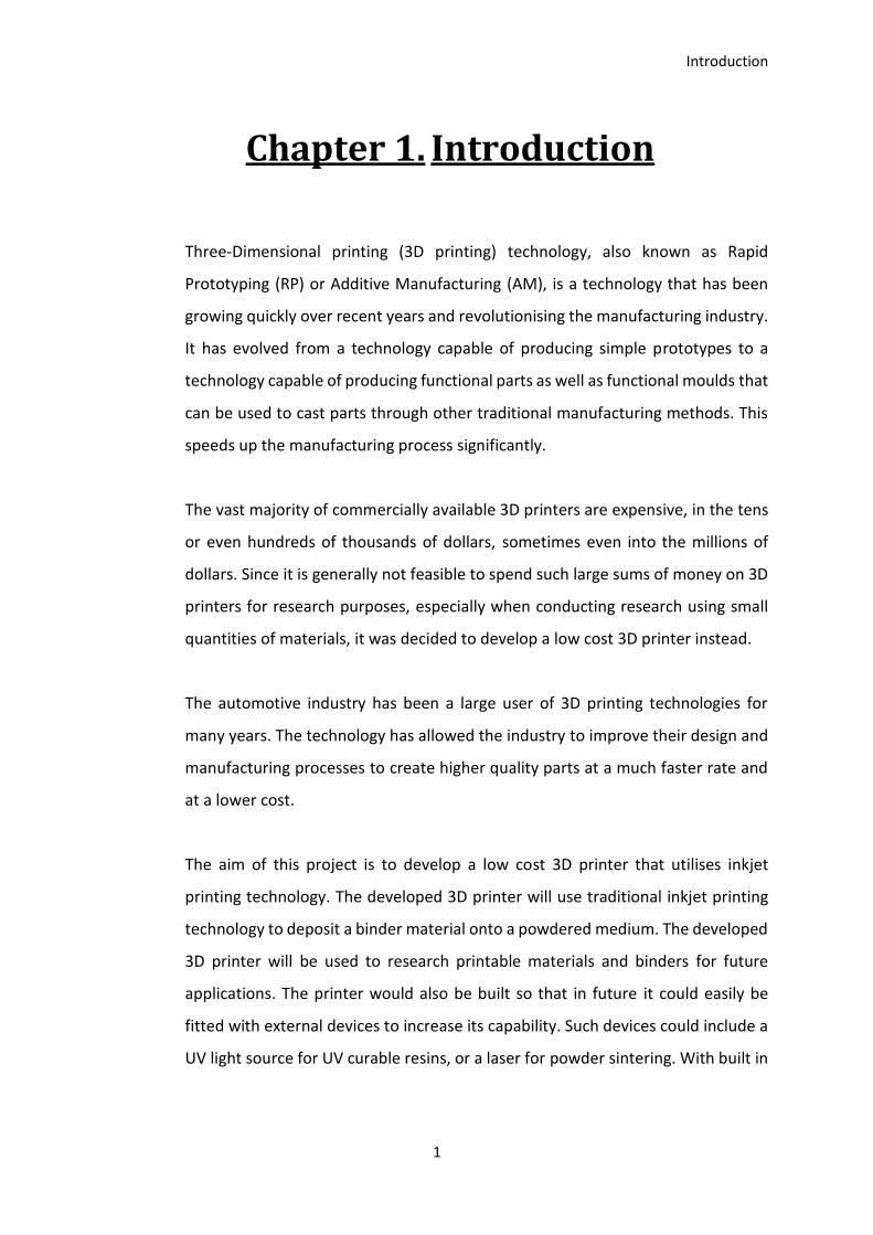
Three-Dimensional printing (3D printing) technology, also known as Rapid
Prototyping (RP) or Additive Manufacturing (AM), is a technology that has been
growing quickly over recent years and revolutionising the manufacturing industry.
It has evolved from a technology capable of producing simple prototypes to a
technology capable of producing functional parts as well as functional moulds that
can be used to cast parts through other traditional manufacturing methods. This
speeds up the manufacturing process significantly.
The vast majority of commercially available 3D printers are expensive, in the tens
or even hundreds of thousands of dollars, sometimes even into the millions of
dollars. Since it is generally not feasible to spend such large sums of money on 3D
printers for research purposes, especially when conducting research using small
quantities of materials, it was decided to develop a low cost 3D printer instead.
The automotive industry has been a large user of 3D printing technologies for
many years. The technology has allowed the industry to improve their design and
manufacturing processes to create higher quality parts at a much faster rate and
at a lower cost.
The aim of this project is to develop a low cost 3D printer that utilises inkjet
printing technology. The developed 3D printer will use traditional inkjet printing
technology to deposit a binder material onto a powdered medium. The developed
3D printer will be used to research printable materials and binders for future
applications. The printer would also be built so that in future it could easily be
fitted with external devices to increase its capability. Such devices could include a
UV light source for UV curable resins, or a laser for powder sintering. With built in
Introduction
2
adaptability the developed 3D printer will increase the university’s ability to
research inkjet 3D printing technology and materials.
The objectives of this project are to:
1. Investigate the current state of 3D printing technology, including currently
available low cost 3D printers and the current state of 3D printing in the
Automotive industry.
In order to develop a low cost 3D printer that is suitable for research purposes,
existing technology must be understood. To keep the cost of the developed 3D
printer as low as possible, existing technology will be applied wherever possible.
3D printing has had a large impact on the automotive industry. Investigating the
way the automotive industry uses 3D printing will indicate how inkjet 3D printing
could be applied to the industry.
2. Investigate the applications of inkjet printing technology with 3D printing.
Inkjet printing technology will be investigated to determine the applications for
current technology and to determine what can be implemented in a 3D printer in
order to develop an efficient system at a low cost.
Through investigating current inkjet technology, it can be determined which
aspects of inkjet technology can be applied to a low cost 3D printer.
3. Develop a low cost, powder based 3D printer using inkjet printing technology.
To keep costs down, the 3D printer will be developed using readily available, off
the shelf parts, wherever possible. Any custom parts will be developed in house in
the most cost effective way.
The 3D printer must be developed to allow a variety of powdered materials to be
used within its parameters.
4. Design future capability into the printer hardware.
Introduction
3
The 3D printer must be designed so that it can easily be adapted to use other 3D
printing technologies. Using in house technologies will allow for parts to be easily
duplicated or modified if/when necessary.
1.1 Thesis Outline & Contributions
Chapter 2 introduces the current state of the additive manufacturing industry and
how the automotive industry utilises 3D printing technology. Inkjet printing
technology is discussed to introduce its applications in the 3D printing industry.
Existing 3D printing technology is discussed, with a further in depth discussion of
low cost 3D printers as well as commercial inkjet 3D printers
Chapter 3 details the mechanical components of the 3D printer developed in this
project. The design of the body and motor sub-assemblies, as well as the gantry is
discussed.
Chapter 4 details the electronic components of the 3D printer developed in this
project. Important parts of the circuit are highlighted in detail. as well as
electronics prototyping and printed circuit board design.
Chapter 5 discusses the software used to control the 3D printer developed in this
project. The process that the user goes through to control the 3D printer is
outlined, as well as the communication to the microcontroller.
Chapter 6 details the implementation and testing of the developed 3D printer.
Problems that were faced during these tests are discussed. Adjustments made to
the 3D printer hardware and software to correct these issues are discussed.
Chapter 7 discusses the deliverables of this project and how the objectives have
been successfully met.

Introduction
4
Literature Review
5
Chapter 2. Literature Review
2.1 Additive Manufacturing
Three-Dimensional printing technology, also known as Rapid Prototyping or
Additive Manufacturing, has been around since the 1980s. Hideo Kodama of
Nagoya Municipal Industrial Research Institute (Japan) invented the first two 3D
printing methods in 1981. These methods used controlled Ultra-Violet light
exposure to cure a photo-hardening polymer (Kodama, 1981).
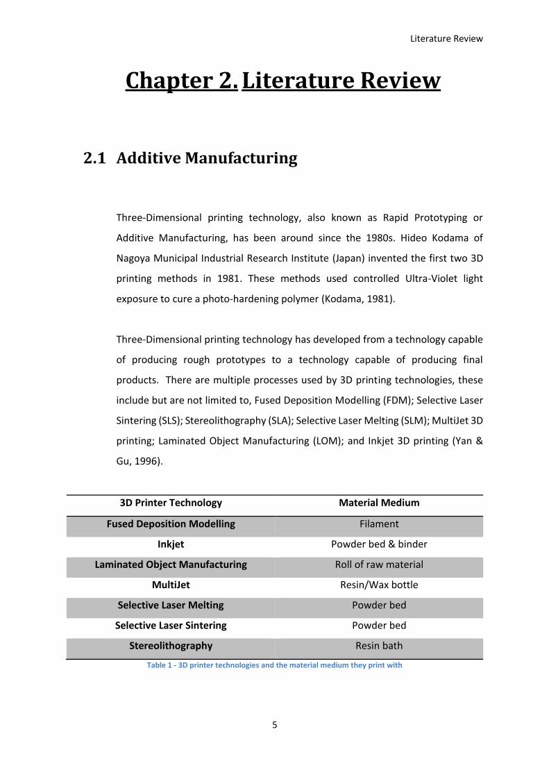
Three-Dimensional printing technology has developed from a technology capable
of producing rough prototypes to a technology capable of producing final
products. There are multiple processes used by 3D printing technologies, these
include but are not limited to, Fused Deposition Modelling (FDM); Selective Laser
Sintering (SLS); Stereolithography (SLA); Selective Laser Melting (SLM); MultiJet 3D
printing; Laminated Object Manufacturing (LOM); and Inkjet 3D printing (Yan &
Gu, 1996).
3D Printer Technology Material Medium
Fused Deposition Modelling Filament
Inkjet Powder bed & binder
Laminated Object Manufacturing Roll of raw material
MultiJet Resin/Wax bottle
Selective Laser Melting Powder bed
Selective Laser Sintering Powder bed
Stereolithography Resin bath
Table 1 - 3D printer technologies and the material medium they print with

Literature Review
6
Rapid Prototyping has widespread use in the industrial and manufacturing sector,
and is used by large corporations to improve the development of their products.
Rapid Prototyping allows designers and engineers to design parts using CAD
software, and then quickly turn them into a working prototype without the need
for expensive tools, thus allowing the prototype to be produced at a relatively low
cost. This allows the designer/engineer to physically handle the part and find any
unforeseen errors within the CAD model. Another advantage of rapid prototyping
is the ability to develop tools for part moulds. The rapid prototyped part can even
be used as a master pattern in some situations. With the ability to quickly and
cheaply prototype parts, it is possible to get higher quality, more complex parts to
production sooner and at a lower overall cost (Yan & Gu, 1996).
Each different technology has its own advantages and disadvantages due to the
natures of the technology. For example, Fused Deposition Modelling is very easy
to implement at a low cost for plastic printers (such as ABS or PLA plastics). These
are common for consumer level 3D printers. However, when extruding plastics it
is a common problem for parts to warp due to temperature differences within the
part as it prints. As the print starts, all the extruded plastic is an even temperature.
As the print progresses the starting layers begin to cool down, while the new
material being deposited on top is still hot. This means that ideally the printer will
have a controlled environment around the print bed (some consumer level FDM
3D printers have this, many don’t. The vast majority of commercial level FDM 3D
printers do have controlled environments), however in doing so this makes it
difficult to have a large print volume, especially with a low cost machine. (Ainsley,
Reis, & Derby, 2002)
Other technologies, such as Stereolithography (SLA) and Inkjet 3D printers do not
have the same issues as no heat is required throughout the printing process. As no
heat is required, it is theoretically possible to scale the print volume to any size.
The downside to this is that they both require material to be deposited before a
layer can be printed (SLA has a resin bath and Inkjet has a powder bed). This means
extra material is required than the part needs in order to complete the print (FDM
Literature Review
7
extrudes the required amount of material, including support material), this
increases the initial cost of the print as a significant amount of extra material is
required. As the size of the print area is increased, the initial costs of running the
machine also quickly increase. Because of this, large machines are not very
common.
Laser based 3D printing technologies, such as Selective Laser Sintering (SLS),
Selective Laser Melting (SLM), and Electron Beam Melting (EBM), are generally
only commercial level technologies, though there are some emerging low cost SLS
3D printers as discussed in section 2.4.2. There are a few reasons for this, such as
cost, external hardware required (3-phase power, compressors, etc.), machine
size, peripheral equipment (for cleaning parts and preparing prints i.e. sieve,
mixer, bead-blaster). These technologies also require extra equipment in order to
make them safe to use. SLM/DMP 3D printing systems must fill the print chamber
with an inert gas such as Nitrogen or Argon. The inert gas prevents the metal
power from oxidising or combusting (3DSystems, N.D.-d)
2.2 Inkjet Printing Technology
The original concept for inkjet printing was patented by Lord William Kelvin, a 19th
century physicist and polymath, “for the direction of droplets through electrostatic
forces.” This technology was not actually developed until the 1950s due to the
inability to “generated detailed instructions to steer the droplets” (Brian Derby,
2010).
Siemens first introduced commercial inkjet printing technology in the 1950’s on a
medical strip chart recorder. Inkjet printers that could print digital images were
developed by Epson, Hewlett-Packard (HP), and Canon in the 1970’s where they
started to become consumer level items (Brian Derby, 2010).
Literature Review
8
Inkjet 3D printing technology mainly uses one of two methods to deliver the ink
onto the powder print bed. These two methods are Drop-on-demand (DOD) Inkjet
printing or Continuous Inkjet printing. Each method has its own advantages and
disadvantages (Ainsley et al., 2002).
2.2.1 How an Inkjet Print Head Works
Inkjet print heads can be split into two main types based on the way they operate:
Continuous (also known as Continuous Inkjet Coding or CIJ) and Drop-on-Demand
(DOD).
Continuous inkjet technology uses a stream of ink, continuously flowing from a
nozzle, by use of pressure, to form drops. The stream of ink is broken into
individual drops through the introduction of disturbances at a particular
wavelength. The drop formation can be accurately controlled through use of a
“regular disturbance at the correct frequency (for example with a piezoelectric
transducer)” (Martin, Hoath, & Hutchings, 2008). Once the stream has been
broken into uniform, individual drops, certain drops are “selected individually for
printing” (Martin et al., 2008). One commonly used method for selecting drops is
to use a conductive ink that is charged via induction as the drop forms. This
method uses an electrode near the stream “held at an appropriate potential”
(Martin et al., 2008) and allows each drop to be charged with a different voltage.
The drops then fall through an electric field. This electric field deflects the charged
drops by a different amount depending on their charge. Charged drops are
directed to the printing medium, whereas uncharged drops fall into the catcher
and are fed back into the ink reservoir to be reused (Blazdell & Evans, 2000).
Drop-on-demand inkjet technology uses one nozzle or an array of nozzles on the
print head to eject individual drops of ink (per nozzle) when needed. The two most
Literature Review
9
common methods of ejecting the ink are “the creation of a vapour bubble within
the ink using a heater pad (‘bubble jet’) or the distortion of a piezoelectric ceramic
element” (Martin et al., 2008). Thermal DOD print heads are used by Canon,
Hewlett-Packard (HP), and Lexmark. Piezoelectric DOD print heads are used by
Epson and Brother Industries (Haigh, 2016).
As the drop is ejected from the nozzle it is first followed by a tail that is still
attached to the nozzle due to surface tension of the ink. At some point after the
initial ejection, the tail breaks away from the drop. Some of the tail returns to the
nozzle, while the rest either joins the drop or breaks away entirely forming
“smaller satellite drops”. Once a drop has been ejected, the cavity created in the
nozzle must be filled, and “any acoustic disturbance must have attenuated enough
to not affect the formation of the next drop” (Martin et al., 2008).
Drop-on-demand inkjet technology is simpler in principal as it only needs to eject
ink when required, as opposed to controlling a continuously flowing stream of ink;
however it can be harder to manufacture the print head (Martin et al., 2008).
2.3 Inkjet 3D Printers
Inkjet printing has been used commercially for graphical applications for a number
of years. Recently inkjet printing has been investigated for use in “displays, plastic
electronics, rapid prototyping, tissue engineering, and ceramic component
manufacture” (B Derby, 2011). In conventional inkjet printing, the print head
separates individual drops on the printing surface. These individual drops are
controlled so that the desired graphic effect is achieved. Due to the nature of the
new applications, the drops are required to be connected to one another in order
to create a continuous structure, whether 1, 2, or 3-Dimensional (B Derby, 2011).
Literature Review
10
There are a range of commercially available Inkjet 3D printers available today, a
few of which are listed in Table 2, that are mainly split into two types. One of these
types, known as material jetting, the print head ejects the build material onto the
print bed (Wohlers & Caffrey, 2015). The parts are built up layer by layer, usually
from a UV cured resin with a wax support material. These parts require post
processing to clean the support material off after printing, though ejecting the
print material from the print head has some advantages over a powder bed as it is
very easy to print in multiple materials at the same time. This can be done through
different nozzles in the print head for the different materials, allowing parts to be
3D printed with different, customisable physical properties. The other type of
inkjet 3D printer, known as binder jetting, uses a powder bed that the print head
deposits a binder onto. These 3D printers can come with full colour capabilities, as
discussed in section 2.3.1. After printing the parts only need to be removed from
the powder bed and brushed clean, there is no need for support material as the
part is supported in the powder bed, similar to the SLS 3D printing process
(3DSystems, N.D.-b).
3D Printer Manufacturer
S Print/M Print Range ExOne
Jet Fusion HP
Objet Series Stratasys
ProJet Series 3D Systems
ProJet MJP Series 3D Systems
VX Series Voxeljet
Table 2 - Available 3D printers that use inkjet technology
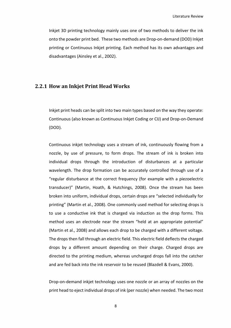
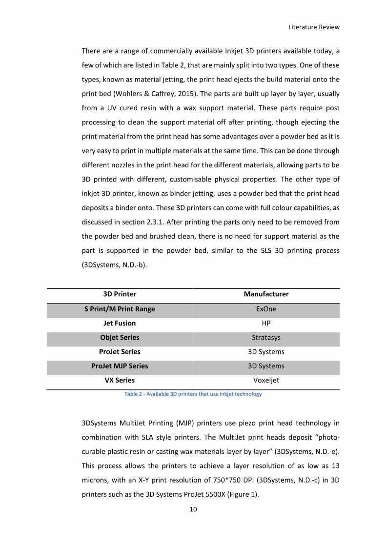
3DSystems MultiJet Printing (MJP) printers use piezo print head technology in
combination with SLA style printers. The MultiJet print heads deposit “photo-
curable plastic resin or casting wax materials layer by layer” (3DSystems, N.D.-e).
This process allows the printers to achieve a layer resolution of as low as 13
microns, with an X-Y print resolution of 750*750 DPI (3DSystems, N.D.-c) in 3D
printers such as the 3D Systems ProJet 5500X (Figure 1).
Literature Review
11
Figure 1 - 3D Systems ProJet 5500X Multi-material 3D printer (Grunewald, 2015)
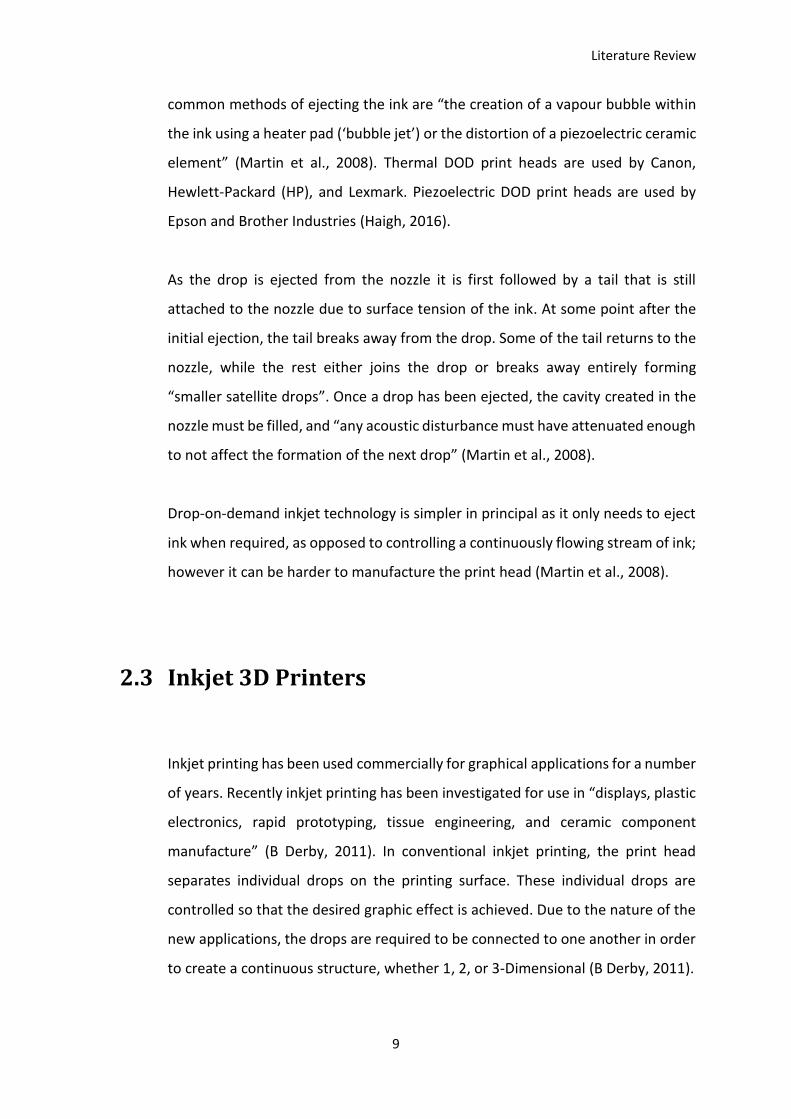
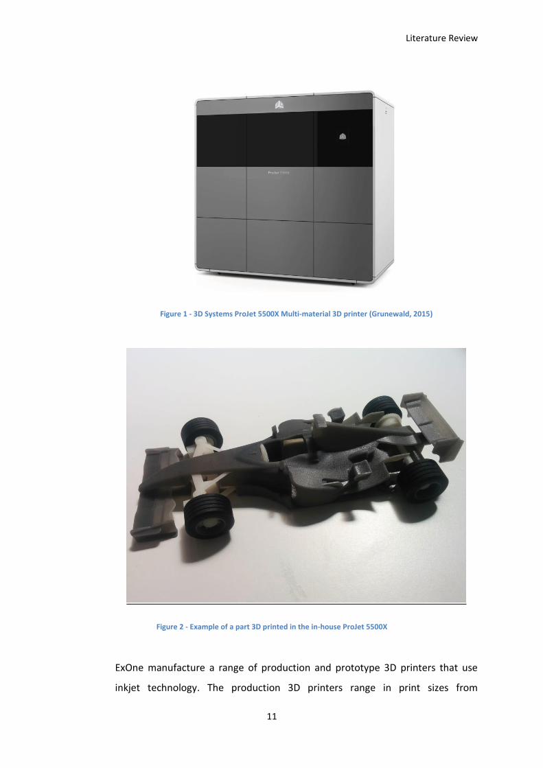
Figure 2 - Example of a part 3D printed in the in-house ProJet 5500X
ExOne manufacture a range of production and prototype 3D printers that use
inkjet technology. The production 3D printers range in print sizes from
Literature Review
12
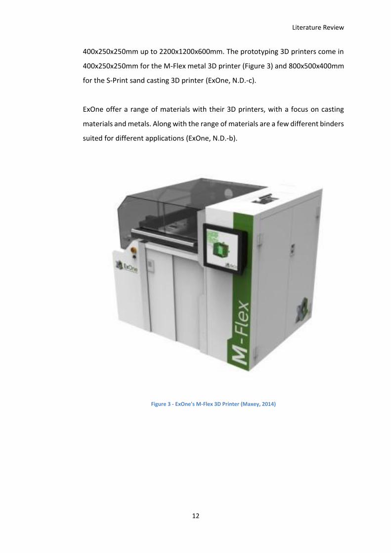
400x250x250mm up to 2200x1200x600mm. The prototyping 3D printers come in
400x250x250mm for the M-Flex metal 3D printer (Figure 3) and 800x500x400mm
for the S-Print sand casting 3D printer (ExOne, N.D.-c).
ExOne offer a range of materials with their 3D printers, with a focus on casting
materials and metals. Along with the range of materials are a few different binders
suited for different applications (ExOne, N.D.-b).
Figure 3 - ExOne's M-Flex 3D Printer (Maxey, 2014)
Literature Review
13
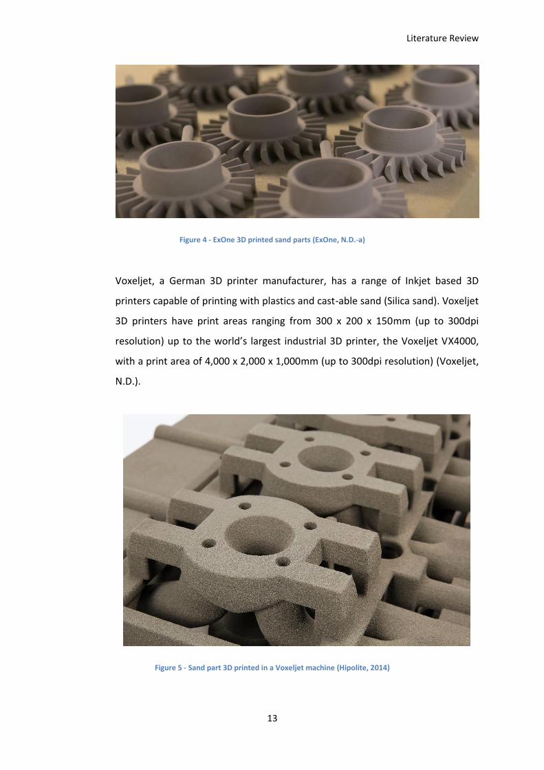
Figure 4 - ExOne 3D printed sand parts (ExOne, N.D.-a)
Voxeljet, a German 3D printer manufacturer, has a range of Inkjet based 3D
printers capable of printing with plastics and cast-able sand (Silica sand). Voxeljet
3D printers have print areas ranging from 300 x 200 x 150mm (up to 300dpi
resolution) up to the world’s largest industrial 3D printer, the Voxeljet VX4000,
with a print area of 4,000 x 2,000 x 1,000mm (up to 300dpi resolution) (Voxeljet,
N.D.).
Figure 5 - Sand part 3D printed in a Voxeljet machine (Hipolite, 2014)
Literature Review
14
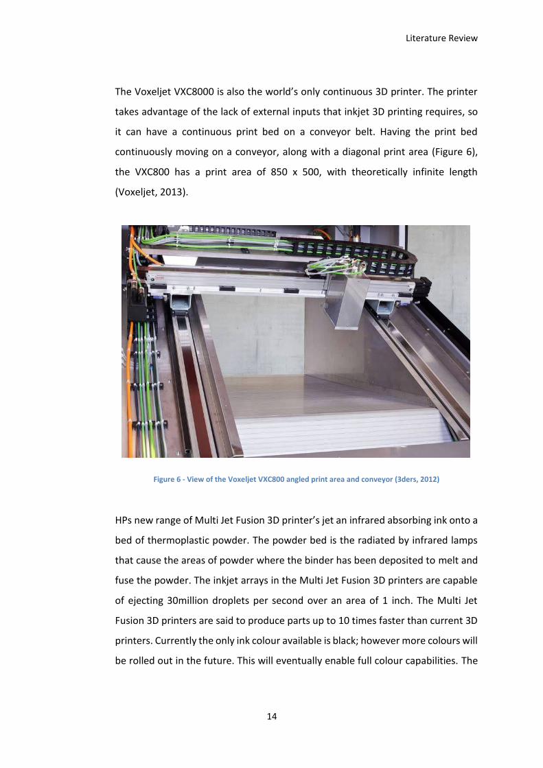
The Voxeljet VXC8000 is also the world’s only continuous 3D printer. The printer
takes advantage of the lack of external inputs that inkjet 3D printing requires, so
it can have a continuous print bed on a conveyor belt. Having the print bed
continuously moving on a conveyor, along with a diagonal print area (Figure 6),
the VXC800 has a print area of 850 x 500, with theoretically infinite length
(Voxeljet, 2013).
Figure 6 - View of the Voxeljet VXC800 angled print area and conveyor (3ders, 2012)
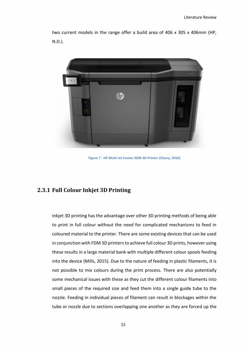
HPs new range of Multi Jet Fusion 3D printer’s jet an infrared absorbing ink onto a
bed of thermoplastic powder. The powder bed is the radiated by infrared lamps
that cause the areas of powder where the binder has been deposited to melt and
fuse the powder. The inkjet arrays in the Multi Jet Fusion 3D printers are capable
of ejecting 30million droplets per second over an area of 1 inch. The Multi Jet
Fusion 3D printers are said to produce parts up to 10 times faster than current 3D
printers. Currently the only ink colour available is black; however more colours will
be rolled out in the future. This will eventually enable full colour capabilities. The
Literature Review
15
two current models in the range offer a build area of 406 x 305 x 406mm (HP,
N.D.).
Figure 7 - HP Multi Jet Fusion 3200 3D Printer (Cleary, 2016)
2.3.1 Full Colour Inkjet 3D Printing
Inkjet 3D printing has the advantage over other 3D printing methods of being able
to print in full colour without the need for complicated mechanisms to feed in
coloured material to the printer. There are some existing devices that can be used
in conjunction with FDM 3D printers to achieve full colour 3D prints, however using
these results in a large material bank with multiple different colour spools feeding
into the device (Mills, 2015). Due to the nature of feeding in plastic filaments, it is
not possible to mix colours during the print process. There are also potentially
some mechanical issues with these as they cut the different colour filaments into
small pieces of the required size and feed them into a single guide tube to the
nozzle. Feeding in individual pieces of filament can result in blockages within the
tube or nozzle due to sections overlapping one another as they are forced up the
Literature Review
16
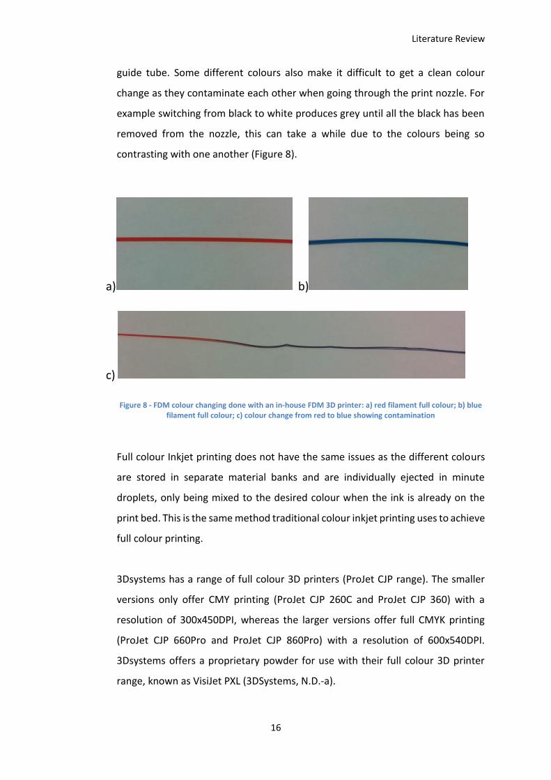
guide tube. Some different colours also make it difficult to get a clean colour
change as they contaminate each other when going through the print nozzle. For
example switching from black to white produces grey until all the black has been
removed from the nozzle, this can take a while due to the colours being so
contrasting with one another (Figure 8).
a) b)
c)
Figure 8 - FDM colour changing done with an in-house FDM 3D printer: a) red filament full colour; b) blue filament full colour; c) colour change from red to blue showing contamination
Full colour Inkjet printing does not have the same issues as the different colours
are stored in separate material banks and are individually ejected in minute
droplets, only being mixed to the desired colour when the ink is already on the
print bed. This is the same method traditional colour inkjet printing uses to achieve
full colour printing.
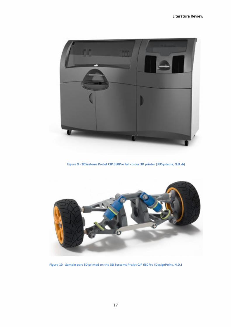
3Dsystems has a range of full colour 3D printers (ProJet CJP range). The smaller
versions only offer CMY printing (ProJet CJP 260C and ProJet CJP 360) with a
resolution of 300x450DPI, whereas the larger versions offer full CMYK printing
(ProJet CJP 660Pro and ProJet CJP 860Pro) with a resolution of 600x540DPI.
3Dsystems offers a proprietary powder for use with their full colour 3D printer
range, known as VisiJet PXL (3DSystems, N.D.-a).
Literature Review
17
Figure 9 - 3DSystems ProJet CJP 660Pro full colour 3D printer (3DSystems, N.D.-b)
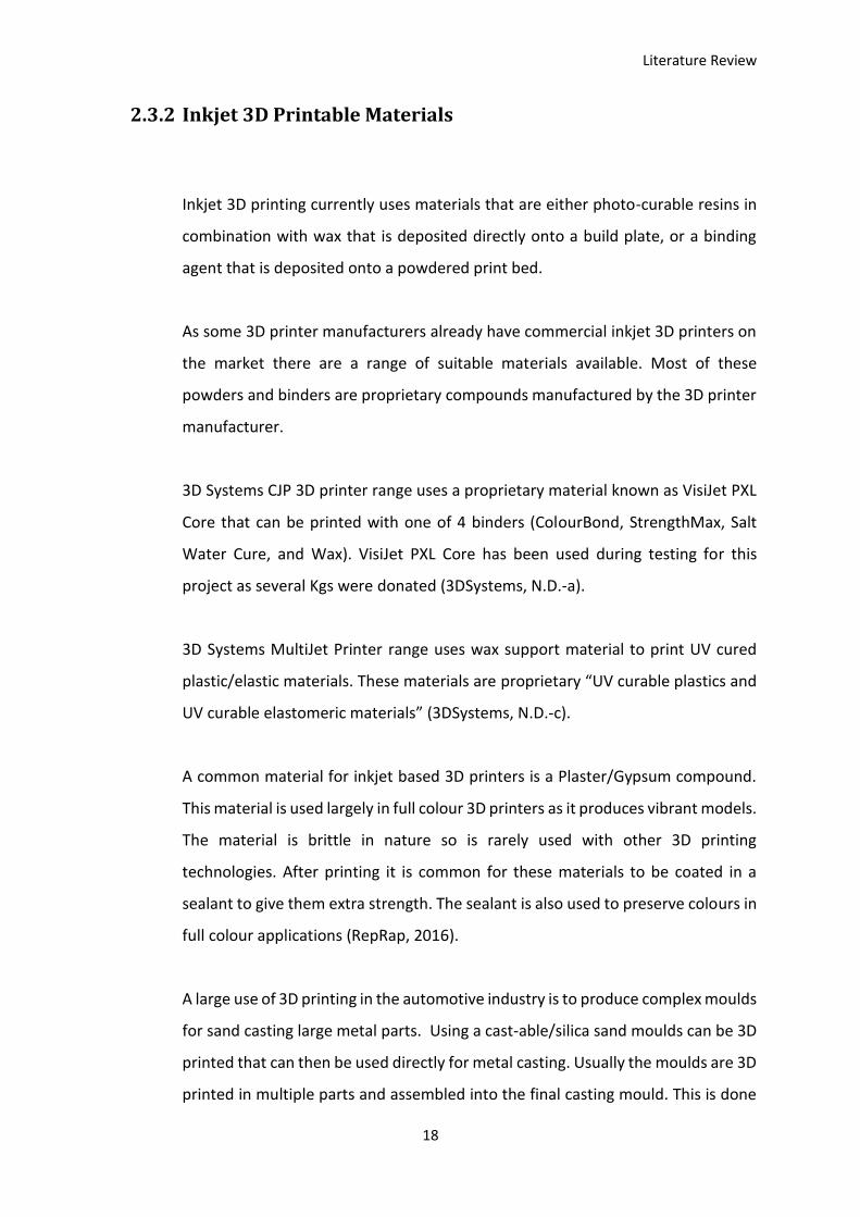
Figure 10 - Sample part 3D printed on the 3D Systems ProJet CJP 660Pro (DesignPoint, N.D.)
Literature Review
18
2.3.2 Inkjet 3D Printable Materials
Inkjet 3D printing currently uses materials that are either photo-curable resins in
combination with wax that is deposited directly onto a build plate, or a binding
agent that is deposited onto a powdered print bed.
As some 3D printer manufacturers already have commercial inkjet 3D printers on
the market there are a range of suitable materials available. Most of these
powders and binders are proprietary compounds manufactured by the 3D printer
manufacturer.
3D Systems CJP 3D printer range uses a proprietary material known as VisiJet PXL
Core that can be printed with one of 4 binders (ColourBond, StrengthMax, Salt
Water Cure, and Wax). VisiJet PXL Core has been used during testing for this
project as several Kgs were donated (3DSystems, N.D.-a).
3D Systems MultiJet Printer range uses wax support material to print UV cured
plastic/elastic materials. These materials are proprietary “UV curable plastics and
UV curable elastomeric materials” (3DSystems, N.D.-c).
A common material for inkjet based 3D printers is a Plaster/Gypsum compound.
This material is used largely in full colour 3D printers as it produces vibrant models.
The material is brittle in nature so is rarely used with other 3D printing
technologies. After printing it is common for these materials to be coated in a
sealant to give them extra strength. The sealant is also used to preserve colours in
full colour applications (RepRap, 2016).
A large use of 3D printing in the automotive industry is to produce complex moulds
for sand casting large metal parts. Using a cast-able/silica sand moulds can be 3D
printed that can then be used directly for metal casting. Usually the moulds are 3D
printed in multiple parts and assembled into the final casting mould. This is done
Literature Review
19
so that the foundry involved in the casting process can ensure that the mould is
clean of any excess powder after the 3D printing process to ensure a clean cast
without contamination. Any powder left in the mould from the 3D printing process
would result in voids in the finished cast part (Bunkley, 2014).
Metal parts can be produced through inkjet 3D printing with metallic powders. The
powder is bonded with specially formulated binders that will burn out during post
processing. After the printing process is complete the parts are removed from the
powder and then dried in a kiln to ensure there is no moisture in the parts. This
baking process will also harden the binder in the parts. Once dried the parts are
then infused with bronze to properly harden them. Since the parts are porous from
the powder printing process, the bronze is easily absorbed into them to produced
solid metal parts (i.materialise, 2010)
Inkjet 3D printers are capable of printing in a wide range of materials, with most
commercial machines focusing on cast-able sands, gypsum, plastics, and waxes.
Each company has their own proprietary materials and binders to go with their
inkjet 3D printers.
2.3.3 Automotive use of Inkjet 3D Printers
The Automotive industry (as well as many other companies) currently uses 3D
printers to prototype parts long before production is ready to begin. This means
parts can be perfected before tooling costs are considered, resulting in parts that
have been designed far better. In the past, when companies had to invest lots into
tooling early on in the process, they were better off to make minimal changes after
going through the tooling process as it would be expensive to have to go through
the tooling process again. Some automotive manufacturers are even using 3D
Literature Review
20
printed parts as functional pieces of their cars, rather than just as prototypes
(Mearian, 2014) (Koenigsegg, 2014b).
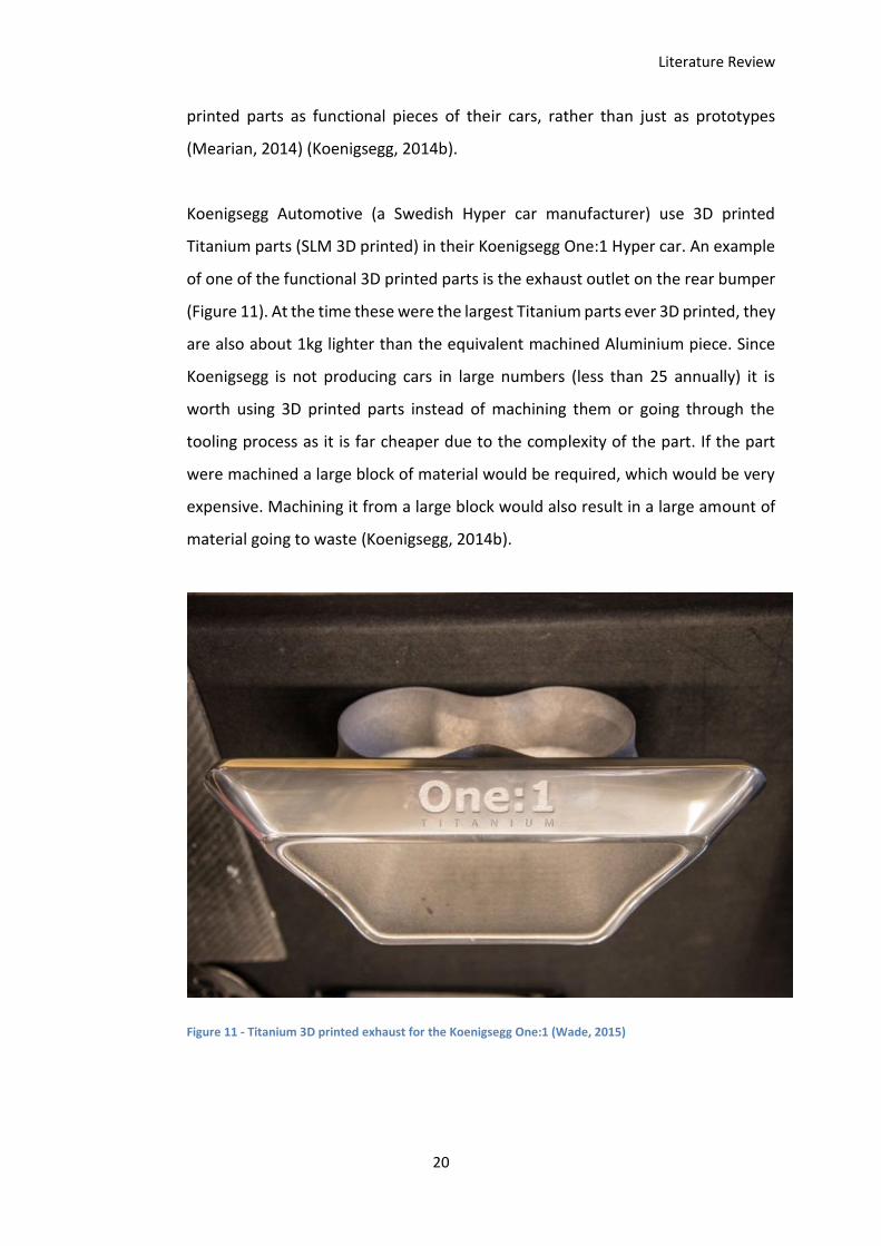
Koenigsegg Automotive (a Swedish Hyper car manufacturer) use 3D printed
Titanium parts (SLM 3D printed) in their Koenigsegg One:1 Hyper car. An example
of one of the functional 3D printed parts is the exhaust outlet on the rear bumper
(Figure 11). At the time these were the largest Titanium parts ever 3D printed, they
are also about 1kg lighter than the equivalent machined Aluminium piece. Since
Koenigsegg is not producing cars in large numbers (less than 25 annually) it is
worth using 3D printed parts instead of machining them or going through the
tooling process as it is far cheaper due to the complexity of the part. If the part
were machined a large block of material would be required, which would be very
expensive. Machining it from a large block would also result in a large amount of
material going to waste (Koenigsegg, 2014b).
Figure 11 - Titanium 3D printed exhaust for the Koenigsegg One:1 (Wade, 2015)
Literature Review
21
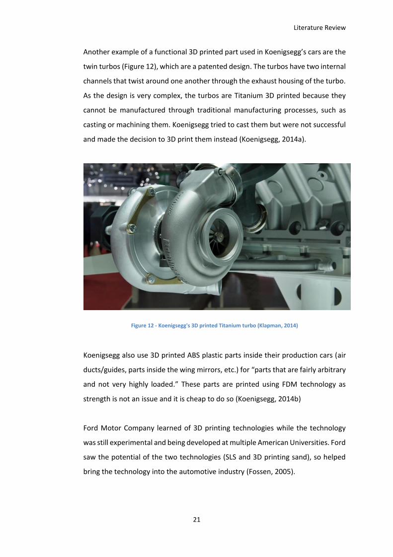
Another example of a functional 3D printed part used in Koenigsegg’s cars are the
twin turbos (Figure 12), which are a patented design. The turbos have two internal
channels that twist around one another through the exhaust housing of the turbo.
As the design is very complex, the turbos are Titanium 3D printed because they
cannot be manufactured through traditional manufacturing processes, such as
casting or machining them. Koenigsegg tried to cast them but were not successful
and made the decision to 3D print them instead (Koenigsegg, 2014a).
Figure 12 - Koenigsegg's 3D printed Titanium turbo (Klapman, 2014)
Koenigsegg also use 3D printed ABS plastic parts inside their production cars (air
ducts/guides, parts inside the wing mirrors, etc.) for “parts that are fairly arbitrary
and not very highly loaded.” These parts are printed using FDM technology as
strength is not an issue and it is cheap to do so (Koenigsegg, 2014b)
Ford Motor Company learned of 3D printing technologies while the technology
was still experimental and being developed at multiple American Universities. Ford
saw the potential of the two technologies (SLS and 3D printing sand), so helped
bring the technology into the automotive industry (Fossen, 2005).
Literature Review
22
When Ford first starting using 3D printing technology, they were producing around
4,000 prototype parts annually, now Ford has five “3D prototyping centres” that
each produce more than 20,000 parts annually. These figures show how much of
an impact 3D printing technology has had on Fords manufacturing process
(Mearian, 2014).
Inkjet 3D printers are capable of printing moulds suitable for making casting
moulds. The ability to 3D print parts of the mould simplifies the casting process
significantly. It allows more complex parts to be cast as all the internal cavities can
be printed as moulds and assembled into one piece. Due to the complexity of some
parts (such as engine blocks or heads) it is not necessarily desirable to print the
entire mould as one piece. In the case of an engine block there are lots of small
internal cavities (oil channels, water channels, etc.) that would mean it is difficult
to ensure all the unbound powder is removed from the mould after the printing
process. Because of this it is easier to print the internal cavity pieces separately
and assemble the mould. This ensures a much cleaner mould and therefore a much
more reliable casting. The cast part usually has dimensionally important parts
machined to the desired finish after the casting process is complete (for example
the top of the cylinder bank on an engine block). Multiple parts can be set up to
print in one machine instead of having to be handmade individually. This
streamlines the manufacturing process as well as significantly reducing the manual
labour involved throughout the manufacturing process (DRIVE, 2013) (Mearian,
2014).
Literature Review
23
2.4 Currently Available Low Cost 3D Printers
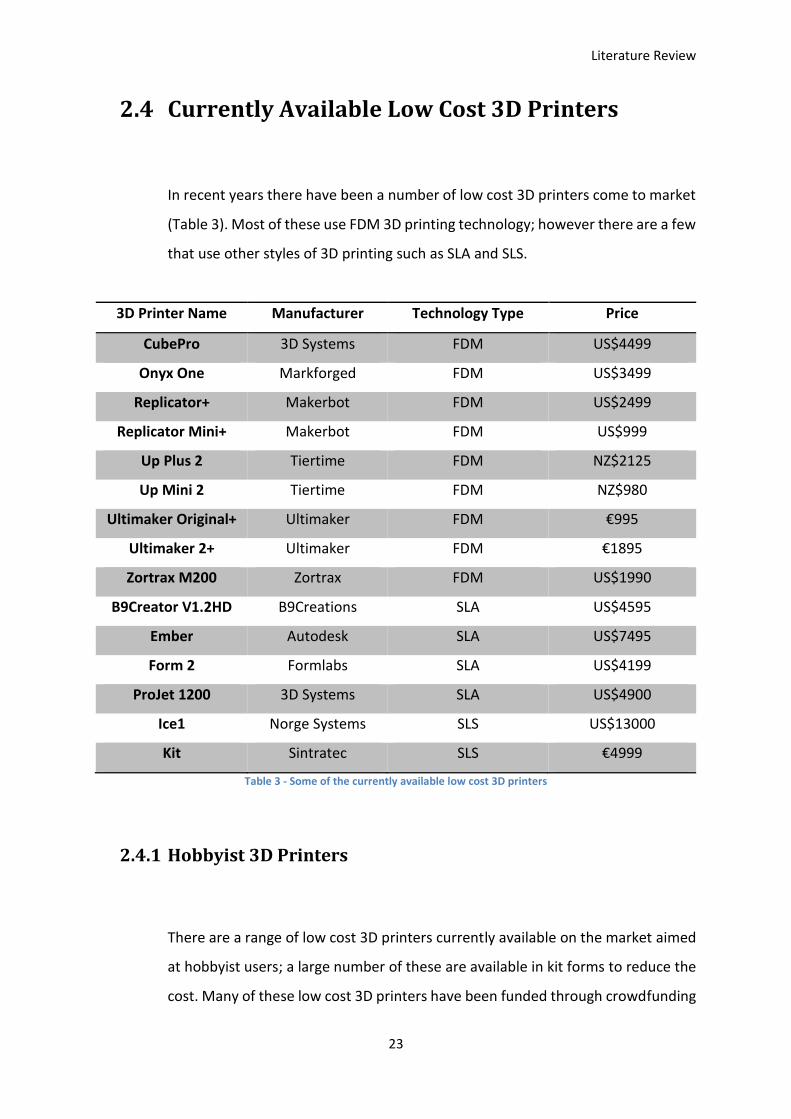
In recent years there have been a number of low cost 3D printers come to market
(Table 3). Most of these use FDM 3D printing technology; however there are a few
that use other styles of 3D printing such as SLA and SLS.
3D Printer Name Manufacturer Technology Type Price
CubePro 3D Systems FDM US$4499
Onyx One Markforged FDM US$3499
Replicator+ Makerbot FDM US$2499
Replicator Mini+ Makerbot FDM US$999
Up Plus 2 Tiertime FDM NZ$2125
Up Mini 2 Tiertime FDM NZ$980
Ultimaker Original+ Ultimaker FDM €995
Ultimaker 2+ Ultimaker FDM €1895
Zortrax M200 Zortrax FDM US$1990
B9Creator V1.2HD B9Creations SLA US$4595
Ember Autodesk SLA US$7495
Form 2 Formlabs SLA US$4199
ProJet 1200 3D Systems SLA US$4900
Ice1 Norge Systems SLS US$13000
Kit Sintratec SLS €4999
Table 3 - Some of the currently available low cost 3D printers
2.4.1 Hobbyist 3D Printers
There are a range of low cost 3D printers currently available on the market aimed
at hobbyist users; a large number of these are available in kit forms to reduce the
cost. Many of these low cost 3D printers have been funded through crowdfunding

Literature Review
24
campaigns. The majority of these 3D printers use FDM technology, which is
relatively cheap and easy to implement. FDM 3D printing is easy to use with
minimal training and requires minimal peripheral equipment (most are self-
contained and only require a standard power port). There are some low cost
desktop SLA and SLS 3D printers; however these are priced slightly higher than the
low cost FDM equivalent 3D printers (3DHubs, 2016).
2.4.2 Low Cost Powder 3D Printers
There are a few emerging companies that have recently crowdfunded projects to
bring low cost SLS 3D printers into the marketplace. Two examples of these are
Norge Systems and Sintratec.
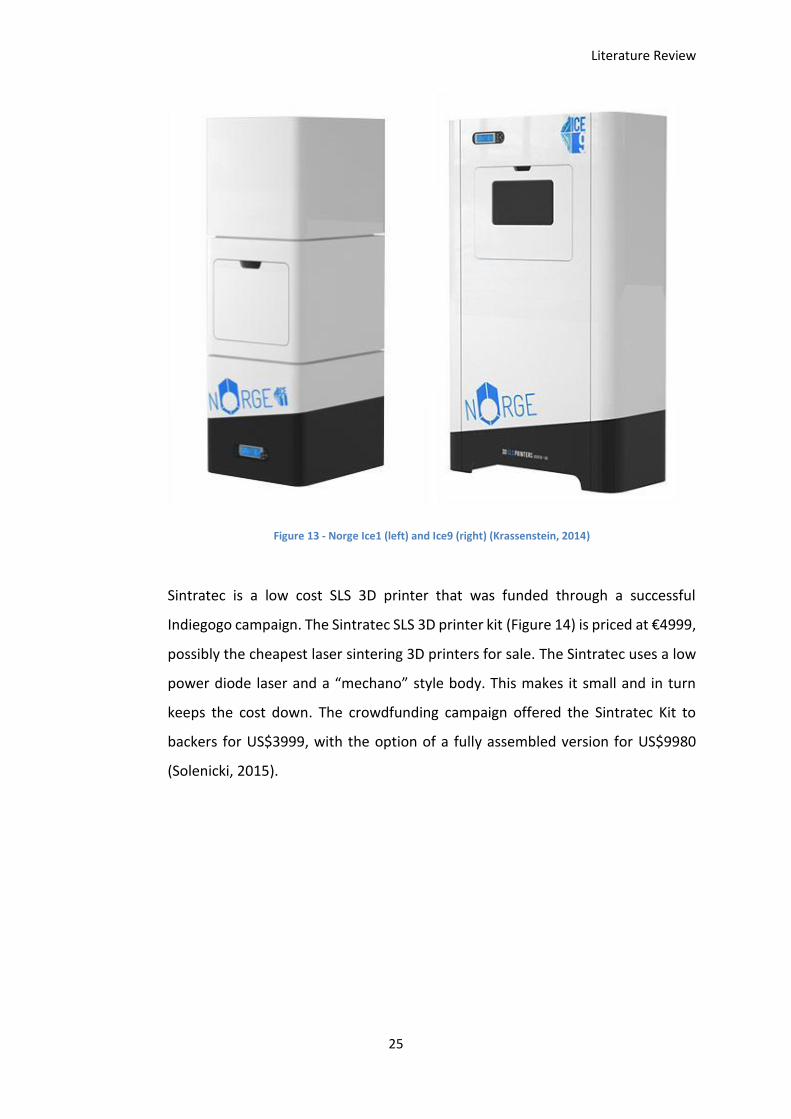
Norge Systems funded their SLS 3D printers, the Ice1 and Ice9 (Figure 13), through
Kickstarter before partnering with Prodways to bring their 3D printers to market.
The original crowdfunding campaign offered the Ice1 to backers for £5000 and the
Ice9 for £19000, with a market sale price of £9000 and £34000 respectively (Norge,
2014).
Literature Review
25
Figure 13 - Norge Ice1 (left) and Ice9 (right) (Krassenstein, 2014)
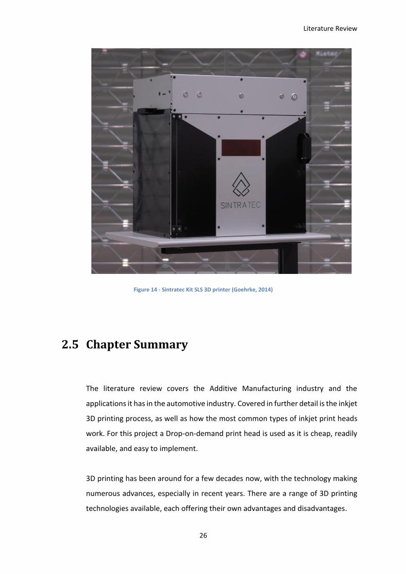
Sintratec is a low cost SLS 3D printer that was funded through a successful
Indiegogo campaign. The Sintratec SLS 3D printer kit (Figure 14) is priced at €4999,
possibly the cheapest laser sintering 3D printers for sale. The Sintratec uses a low
power diode laser and a “mechano” style body. This makes it small and in turn
keeps the cost down. The crowdfunding campaign offered the Sintratec Kit to
backers for US$3999, with the option of a fully assembled version for US$9980
(Solenicki, 2015).
Literature Review
26
Figure 14 - Sintratec Kit SLS 3D printer (Goehrke, 2014)
2.5 Chapter Summary
The literature review covers the Additive Manufacturing industry and the
applications it has in the automotive industry. Covered in further detail is the inkjet
3D printing process, as well as how the most common types of inkjet print heads
work. For this project a Drop-on-demand print head is used as it is cheap, readily
available, and easy to implement.
3D printing has been around for a few decades now, with the technology making
numerous advances, especially in recent years. There are a range of 3D printing
technologies available, each offering their own advantages and disadvantages.

Literature Review
27
Low cost 3D printers are becoming more and more common, with most of them
focused on FDM 3D printing technology there are a few emerging in the market
using other technologies.
Inkjet 3D printers are available on a commercial level implemented in a few
different ways for different applications. There are a range of materials offered in
these commercial machines, most of which are made by the 3D printer
manufacturer and are proprietary compounds. The main material types used in
these commercial machines are casting sands, plaster based materials, and UV
cured resins. A 3D Systems powder known as VisiJet PXL Core was donated for use
in this project.
None of these commercially available machines are viable to use for researching
new materials and binders as they are designed to work with these proprietary
compounds, so do not offer much accessibility to machine settings for research
purposes.

Literature Review
28
Mechanical Components
29
Chapter 3. Mechanical Components
The main idea behind the physical design of the 3D printer was to use an open-
source design to save time and reduce cost. The original design is taken from the
open-source PWDR design, originally designed by Alex Budding of the University
of Twente, Enschede, Netherlands. This style of 3D printer is easy to implement
and does not require complex parts or manufacturing methods to produce.
In order to achieve the low cost aspect of this project, the mechanical components
for the developed 3D printer were sourced from local companies wherever
possible.
All parts are off the shelf items or manufactured in house through advanced
manufacturing techniques, laser cutting or 3D printing. The only parts that are
exceptions to this are the shafts that need to be cut to length, and the roller shaft
that needs to be turned down at both ends to fit within the printer body.
3.1 3D Printer Body
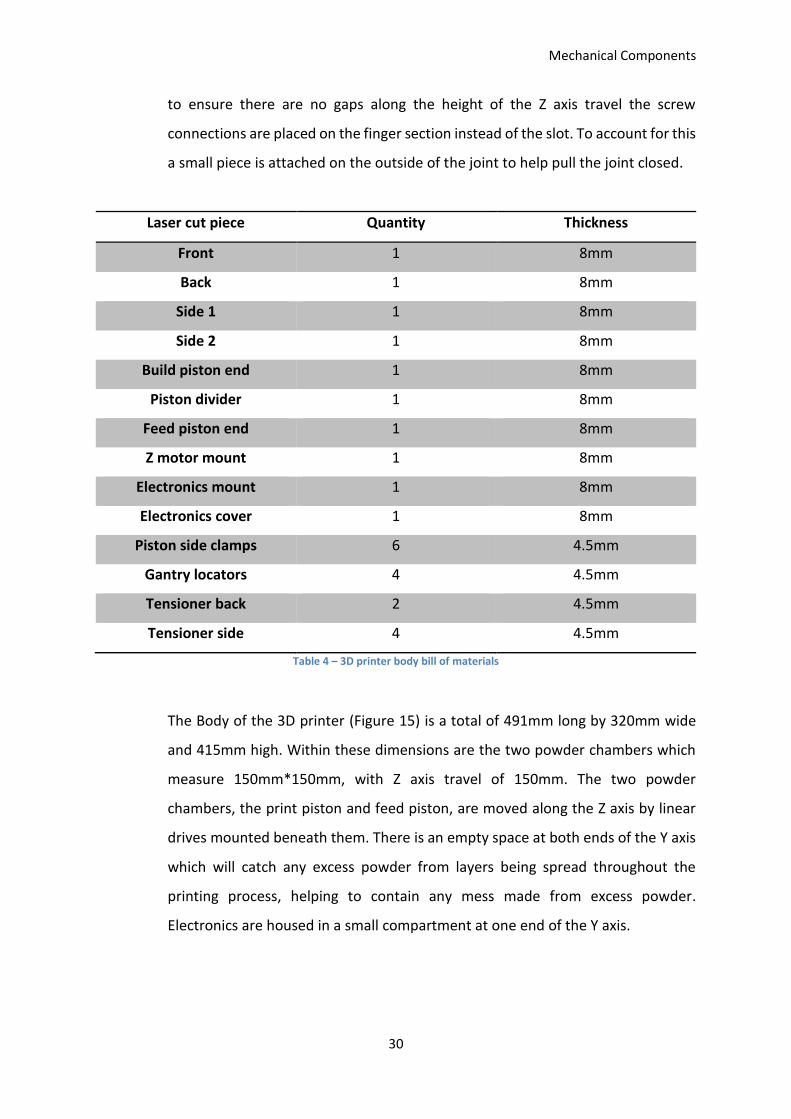
The body of the 3D printer is made 26 pieces laser cut from 8mm and 4.5mm
acrylic (Table 4), which are both standardised sizes and are readily available. The
acrylic was laser cut in house using a Universal Laser Systems PLS6.150D universal
laser cutter. The laser cut parts are assembled using finger/slot joints, each of
which has a slot cut out to hold a captive nut. Each corresponding piece has a hole
cut out for a bolt to ensure a strong connection. This ensures the printer body is
strong and rigid and that it can contain the powder without the need for rubber or
fabric seals along the joints. It also means that the printer body can be
disassembled fairly easily as there are no permanent connections made. In order
Mechanical Components
30
to ensure there are no gaps along the height of the Z axis travel the screw
connections are placed on the finger section instead of the slot. To account for this
a small piece is attached on the outside of the joint to help pull the joint closed.
Laser cut piece Quantity Thickness
Front 1 8mm
Back 1 8mm
Side 1 1 8mm
Side 2 1 8mm
Build piston end 1 8mm
Piston divider 1 8mm
Feed piston end 1 8mm
Z motor mount 1 8mm
Electronics mount 1 8mm
Electronics cover 1 8mm
Piston side clamps 6 4.5mm
Gantry locators 4 4.5mm
Tensioner back 2 4.5mm
Tensioner side 4 4.5mm
Table 4 – 3D printer body bill of materials
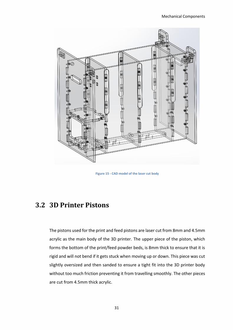
The Body of the 3D printer (Figure 15) is a total of 491mm long by 320mm wide
and 415mm high. Within these dimensions are the two powder chambers which
measure 150mm*150mm, with Z axis travel of 150mm. The two powder
chambers, the print piston and feed piston, are moved along the Z axis by linear
drives mounted beneath them. There is an empty space at both ends of the Y axis
which will catch any excess powder from layers being spread throughout the
printing process, helping to contain any mess made from excess powder.
Electronics are housed in a small compartment at one end of the Y axis.
Mechanical Components
31
Figure 15 - CAD model of the laser cut body
3.2 3D Printer Pistons
The pistons used for the print and feed pistons are laser cut from 8mm and 4.5mm
acrylic as the main body of the 3D printer. The upper piece of the piston, which
forms the bottom of the print/feed powder beds, is 8mm thick to ensure that it is
rigid and will not bend if it gets stuck when moving up or down. This piece was cut
slightly oversized and then sanded to ensure a tight fit into the 3D printer body
without too much friction preventing it from travelling smoothly. The other pieces
are cut from 4.5mm thick acrylic.
Mechanical Components
32
Laser cut piece Quantity Thickness
Piston upper 1 8mm
Piston sides 2 4.5mm
Piston lower 1 4.5mm
Table 5 - 3D printer piston bill of materials
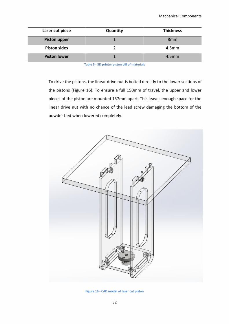
To drive the pistons, the linear drive nut is bolted directly to the lower sections of
the pistons (Figure 16). To ensure a full 150mm of travel, the upper and lower
pieces of the piston are mounted 157mm apart. This leaves enough space for the
linear drive nut with no chance of the lead screw damaging the bottom of the
powder bed when lowered completely.
Figure 16 - CAD model of laser cut piston
Mechanical Components
33
3.3 Motor Sub-assemblies
There are two small sub-assemblies of that house the motors for the X axis and
Roller. These sub-assemblies are mounted on the Y axis shafts and contain the
linear bearings for the Y axis, as well as the bushings for the roller to mount into.
Both of the housings have holes cut into the front pieces to accommodate the two
X axis shafts. These sub-assemblies each mount onto one side of the Y axis and
together support the X axis shafts, roller, and the print head mount.
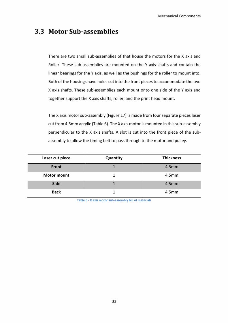
The X axis motor sub-assembly (Figure 17) is made from four separate pieces laser
cut from 4.5mm acrylic (Table 6). The X axis motor is mounted in this sub-assembly
perpendicular to the X axis shafts. A slot is cut into the front piece of the sub-
assembly to allow the timing belt to pass through to the motor and pulley.
Laser cut piece Quantity Thickness
Front 1 4.5mm
Motor mount 1 4.5mm
Side 1 4.5mm
Back 1 4.5mm
Table 6 - X axis motor sub-assembly bill of materials
Mechanical Components
34
Figure 17 - X Axis motor assembly
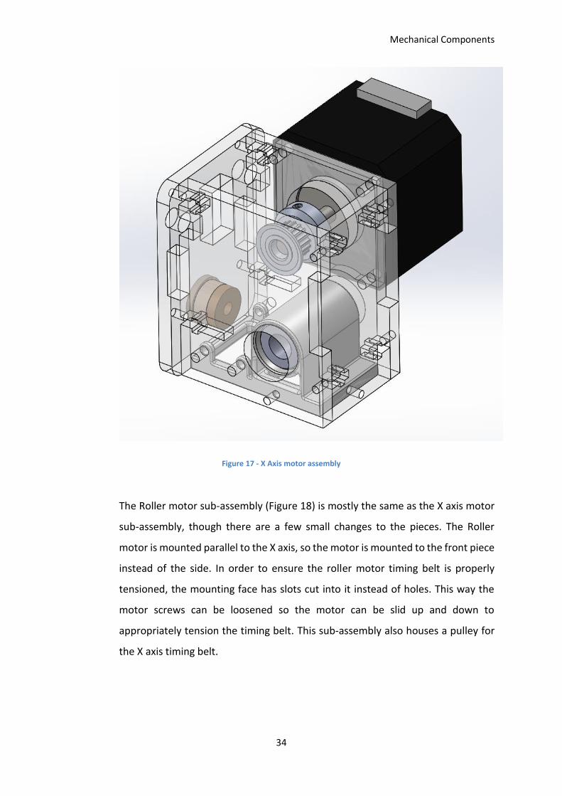
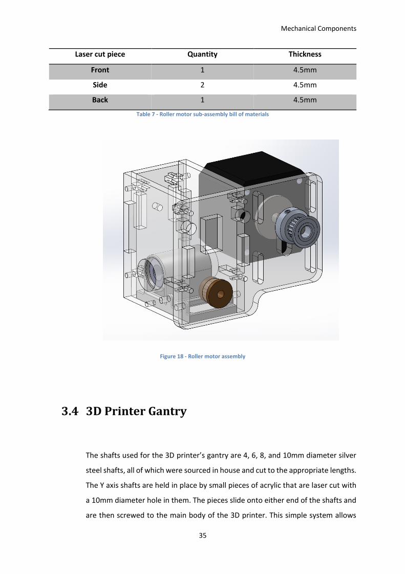
The Roller motor sub-assembly (Figure 18) is mostly the same as the X axis motor
sub-assembly, though there are a few small changes to the pieces. The Roller
motor is mounted parallel to the X axis, so the motor is mounted to the front piece
instead of the side. In order to ensure the roller motor timing belt is properly
tensioned, the mounting face has slots cut into it instead of holes. This way the
motor screws can be loosened so the motor can be slid up and down to
appropriately tension the timing belt. This sub-assembly also houses a pulley for
the X axis timing belt.
Mechanical Components
35
Laser cut piece Quantity Thickness
Front 1 4.5mm
Side 2 4.5mm
Back 1 4.5mm
Table 7 - Roller motor sub-assembly bill of materials
Figure 18 - Roller motor assembly
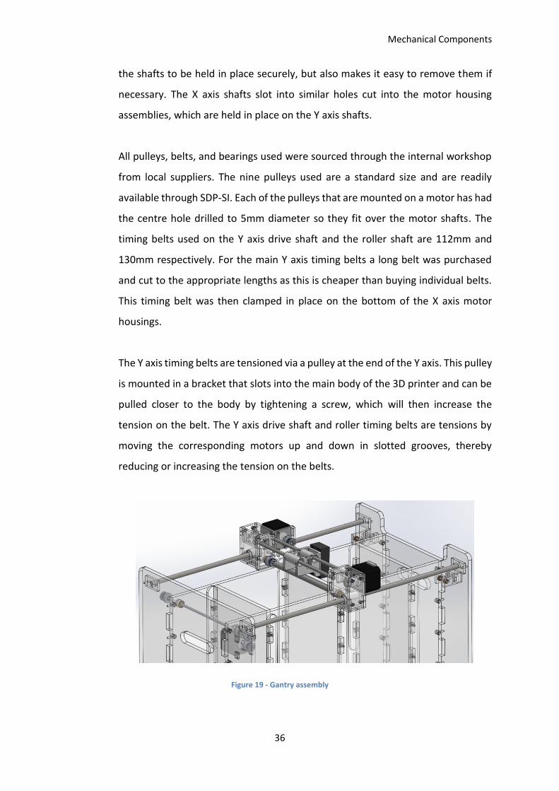
3.4 3D Printer Gantry
The shafts used for the 3D printer’s gantry are 4, 6, 8, and 10mm diameter silver
steel shafts, all of which were sourced in house and cut to the appropriate lengths.
The Y axis shafts are held in place by small pieces of acrylic that are laser cut with
a 10mm diameter hole in them. The pieces slide onto either end of the shafts and
are then screwed to the main body of the 3D printer. This simple system allows
Mechanical Components
36
the shafts to be held in place securely, but also makes it easy to remove them if
necessary. The X axis shafts slot into similar holes cut into the motor housing
assemblies, which are held in place on the Y axis shafts.
All pulleys, belts, and bearings used were sourced through the internal workshop
from local suppliers. The nine pulleys used are a standard size and are readily
available through SDP-SI. Each of the pulleys that are mounted on a motor has had
the centre hole drilled to 5mm diameter so they fit over the motor shafts. The
timing belts used on the Y axis drive shaft and the roller shaft are 112mm and
130mm respectively. For the main Y axis timing belts a long belt was purchased
and cut to the appropriate lengths as this is cheaper than buying individual belts.
This timing belt was then clamped in place on the bottom of the X axis motor
housings.
The Y axis timing belts are tensioned via a pulley at the end of the Y axis. This pulley
is mounted in a bracket that slots into the main body of the 3D printer and can be
pulled closer to the body by tightening a screw, which will then increase the
tension on the belt. The Y axis drive shaft and roller timing belts are tensions by
moving the corresponding motors up and down in slotted grooves, thereby
reducing or increasing the tension on the belts.
Figure 19 - Gantry assembly

Mechanical Components
37
3.5 Chapter Summary
This chapter covers the design and components used in making the body, motor
sub-assemblies, and gantry of the developed 3D printer. The 3D printer body is
made from 38 pieces of laser cut acrylic. All laser cutting has been done in house
using 8mm and 4.5mm thick acrylic. The 3D printer gantry is built using readily
available shafts, bearings, bushings, pulleys, and timing belts.
Mechanical Components
38
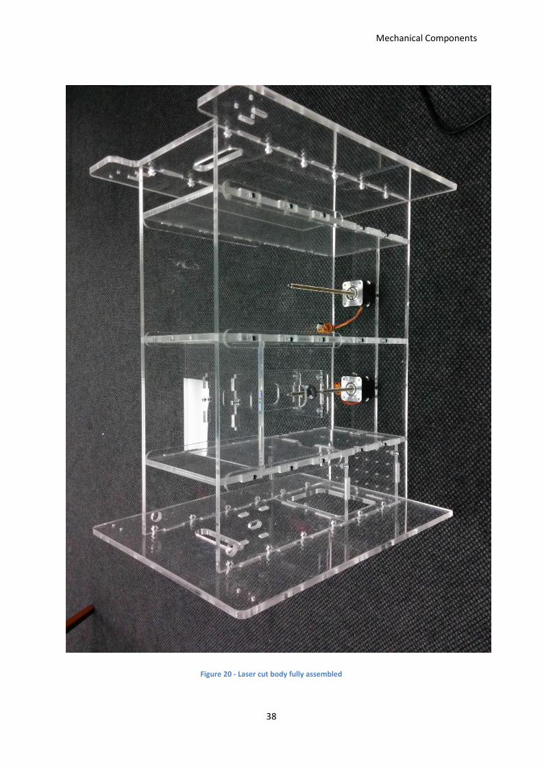
Figure 20 - Laser cut body fully assembled
Electrical Components
39
Chapter 4. Electrical Components
The original open source circuit had various errors through it. Due to
documentation issues with the original schematics, the circuit was remade. The
main idea behind the circuit was kept so that the new design used readily available
components. The new circuit was prototyped in sections using breadboards. The
motor control circuit and print head circuit were prototyped individually before
being combined into one circuit on a veroboard. This was done so that any issues
would be easier to identify and solve. Once the total circuit was proven to work, a
PCB was designed and manufactured.
Since the Arduino Mega used to control the 3D printer has more input/output pins
than are required for this project in its current state, extra pins were allowed for
future development of the 3D printer.
4.1 Arduino
Arduino Mega 2560 provides 54 digital input/output pins; it also provides 16
analogue input pins. 28 pins are required for the printer circuit. Four pins (50-53)
are used for the SD card interface. These four pins are built into the Arduino Mega
to have SPI (Serial Peripheral Interface) capability. Ten pins (36-45) are required
for the stepper drivers; each driver needs a “step” and “direction” input from the
Arduino. Fourteen pins (22-35) are required for the Darlington Arrays. Since 28
pins (minimum) are required, the best option was to use an Arduino Mega 2560
as it is a commonly available and cheap option. Other possibilities such as a
Raspberry Pi or a PIC controller could have been used, however as the original
open-source design used an Arduino there was no point in redesigning lots of the
circuit/code to accommodate the change. The extra input/output pins available
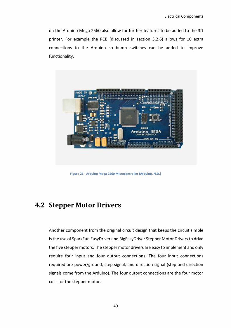
Electrical Components
40
on the Arduino Mega 2560 also allow for further features to be added to the 3D
printer. For example the PCB (discussed in section 3.2.6) allows for 10 extra
connections to the Arduino so bump switches can be added to improve
functionality.
Figure 21 - Arduino Mega 2560 Microcontroller (Arduino, N.D.)
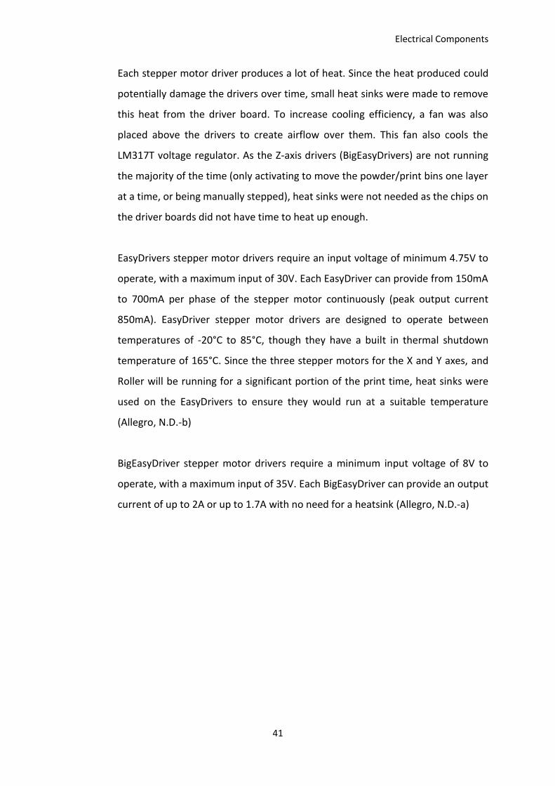
4.2 Stepper Motor Drivers
Another component from the original circuit design that keeps the circuit simple
is the use of SparkFun EasyDriver and BigEasyDriver Stepper Motor Drivers to drive
the five stepper motors. The stepper motor drivers are easy to implement and only
require four input and four output connections. The four input connections
required are power/ground, step signal, and direction signal (step and direction
signals come from the Arduino). The four output connections are the four motor
coils for the stepper motor.
Electrical Components
41
Each stepper motor driver produces a lot of heat. Since the heat produced could
potentially damage the drivers over time, small heat sinks were made to remove
this heat from the driver board. To increase cooling efficiency, a fan was also
placed above the drivers to create airflow over them. This fan also cools the
LM317T voltage regulator. As the Z-axis drivers (BigEasyDrivers) are not running
the majority of the time (only activating to move the powder/print bins one layer
at a time, or being manually stepped), heat sinks were not needed as the chips on
the driver boards did not have time to heat up enough.
EasyDrivers stepper motor drivers require an input voltage of minimum 4.75V to
operate, with a maximum input of 30V. Each EasyDriver can provide from 150mA
to 700mA per phase of the stepper motor continuously (peak output current
850mA). EasyDriver stepper motor drivers are designed to operate between
temperatures of -20°C to 85°C, though they have a built in thermal shutdown
temperature of 165°C. Since the three stepper motors for the X and Y axes, and
Roller will be running for a significant portion of the print time, heat sinks were
used on the EasyDrivers to ensure they would run at a suitable temperature
(Allegro, N.D.-b)
BigEasyDriver stepper motor drivers require a minimum input voltage of 8V to
operate, with a maximum input of 35V. Each BigEasyDriver can provide an output
current of up to 2A or up to 1.7A with no need for a heatsink (Allegro, N.D.-a)
Electrical Components
42
a) b)
Figure 22 - Stepper Motor Drivers during testing of the first prototype. a) X/Y/Roller motor Easy Drivers; b) Z motors BigEasyDrivers
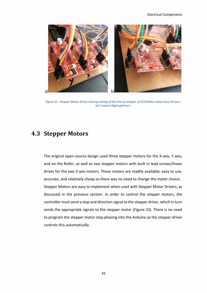
4.3 Stepper Motors
The original open-source design used three stepper motors for the X-axis, Y-axis,
and on the Roller, as well as two stepper motors with built in lead screws/linear
drives for the two Z-axis motors. These motors are readily available, easy to use,
accurate, and relatively cheap so there was no need to change the motor choice.
Stepper Motors are easy to implement when used with Stepper Motor Drivers, as
discussed in the previous section. In order to control the stepper motors, the
controller must send a step and direction signal to the stepper driver, which in turn
sends the appropriate signals to the stepper motor (Figure 23). There is no need
to program the stepper motor step phasing into the Arduino as the stepper driver
controls this automatically.
Electrical Components
43
Figure 23 - Stepper Motor Control Flow Diagram
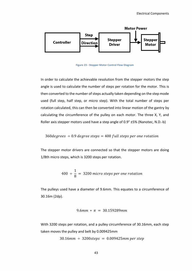
In order to calculate the achievable resolution from the stepper motors the step
angle is used to calculate the number of steps per rotation for the motor. This is
then converted to the number of steps actually taken depending on the step mode
used (full step, half step, or micro step). With the total number of steps per
rotation calculated, this can then be converted into linear motion of the gantry by
calculating the circumference of the pulley on each motor. The three X, Y, and
Roller axis stepper motors used have a step angle of 0.9° ±5% (Nanotec, N.D.-b)
360𝑑𝑒𝑔𝑟𝑒𝑒𝑠 ÷ 0.9 𝑑𝑒𝑔𝑟𝑒𝑒 𝑠𝑡𝑒𝑝𝑠 = 400 𝑓𝑢𝑙𝑙 𝑠𝑡𝑒𝑝𝑠 𝑝𝑒𝑟 𝑜𝑛𝑒 𝑟𝑜𝑡𝑎𝑡𝑖𝑜𝑛
The stepper motor drivers are connected so that the stepper motors are doing
1/8th micro steps, which is 3200 steps per rotation.
400 ÷ 1
8 = 3200 𝑚𝑖𝑐𝑟𝑜 𝑠𝑡𝑒𝑝𝑠 𝑝𝑒𝑟 𝑜𝑛𝑒 𝑟𝑜𝑡𝑎𝑡𝑖𝑜𝑛
The pulleys used have a diameter of 9.6mm. This equates to a circumference of
30.16m (2dp).
9.6𝑚𝑚 ∗ 𝜋 = 30.159289𝑚𝑚
With 3200 steps per rotation, and a pulley circumference of 30.16mm, each step
taken moves the pulley and belt by 0.009425mm
30.16𝑚𝑚 ÷ 3200𝑠𝑡𝑒𝑝𝑠 = 0.009425𝑚𝑚 𝑝𝑒𝑟 𝑠𝑡𝑒𝑝
Electrical Components
44
From the above calculations the number of steps required to move along the X
and Y axes can be calculated.
The X axis travel is 137mm long; therefore it will take 14536 micro steps to travel
from one end to the other.
137𝑚𝑚 ÷ 0.009425𝑚𝑚 𝑝𝑒𝑟 𝑠𝑡𝑒𝑝 = 14535.809 (14536)𝑠𝑡𝑒𝑝𝑠
The Y axis travel is 328mm long; therefore it will take 34801 micro steps to travel
from one end to the other.
328𝑚𝑚 ÷ 0.009425𝑚𝑚 𝑝𝑒𝑟 𝑠𝑡𝑒𝑝 = 34801.061 (34801)𝑠𝑡𝑒𝑝𝑠
The length of the build platform and feed piston along the Y axis is 310mm;
therefore it will take 32891 micro steps to travel the full distance.
310𝑚𝑚 ÷ 0.009425𝑚𝑚 𝑝𝑒𝑟 𝑠𝑡𝑒𝑝 = 32891.247 (32891) 𝑠𝑡𝑒𝑝𝑠
The two Z-axis motors have a step angle of 1.8° ±5%. The linear drive has a pitch
of 1mm (T6*1) (Nanotec, N.D.-a).
360° ÷ 1.8° = 200 𝑠𝑡𝑒𝑝𝑠 𝑝𝑒𝑟 𝑜𝑛𝑒 𝑟𝑜𝑡𝑎𝑡𝑖𝑜𝑛
With 200 steps per rotation and a 1mm pitch along the linear drive, travel per step
is 0.005mm.
1𝑚𝑚 ÷ 200𝑠𝑡𝑒𝑝𝑠 = 0.005𝑚𝑚 𝑝𝑒𝑟 𝑠𝑡𝑒𝑝
In order to achieve a layer thickness of 0.15mm the z axis will need to move 30
steps.
0.15𝑚𝑚 ÷ 0.005𝑚𝑚 𝑝𝑒𝑟 𝑠𝑡𝑒𝑝 = 30 𝑠𝑡𝑒𝑝𝑠
Electrical Components
45
From these calculations the 3D printer motor control can be programmed with the
axis lengths with regards to the number of steps required to travel the full lengths.
4.4 Darlington Arrays
Two ULN2003A Darlington Arrays are used to control each of the nozzles on the
print head. Each chip has an array of seven NPN Darlington transistors, therefore
two are required to control all 12 of the print head nozzles. Each of the seven
outputs on the Darlington Arrays can provide a signal of 50V at 500mA (600mA
peak) (STMicroelectronics, N.D.-b).
The Darlington Array inputs are given signals from the Arduino pins 22-35 and the
COM pin is supplied with 22V through the LM317T Voltage Regulator circuit.
4.5 Print head and Carrier
To deposit binder onto the powder an HP C6602A print head is used. The C6602A
is a thermal Drop-on-demand print head that comes with black printer ink. A
thermal DOD print head is best suited for this project as it is easy to implement
and can work with a range of binders.
The HP C6602A print head is readily available, cheap, and can be refilled once
empty. To refill the print head the binder can be injected into a small hole in the
top of the print head by using a syringe. Since it is a thermal DOD print head it can
be refilled with a range of liquids, including water/alcohol mixtures.

Electrical Components
46
The print head is mounted in an HP Q2347A Carriage Assembly. This carriage is
designed to house the C6602 range of print heads and includes the ribbon cable
required for the print head connections.
The C6602 range of print heads each have 12 nozzles with a swath width of 1/8th
of an inch, or 3.175mm. They require a 21V pulse 6µs long in order to eject ink
from a single nozzle. To fire nozzles one after another a 0.5µs delay is required,
and an 800µs delay between pulses on one nozzle (Lewis, N.D.)
4.6 Power Supplies
The circuit uses two separate power supplies to drive the print head control as
well as the stepper motor control. Both power supplies were obtained from the
electronics lab and so did not need to be purchased. An advantage to having two
separate power supplies allowed the different sections to be easily isolated during
testing, including having them connected to a common ground or completely
isolated.
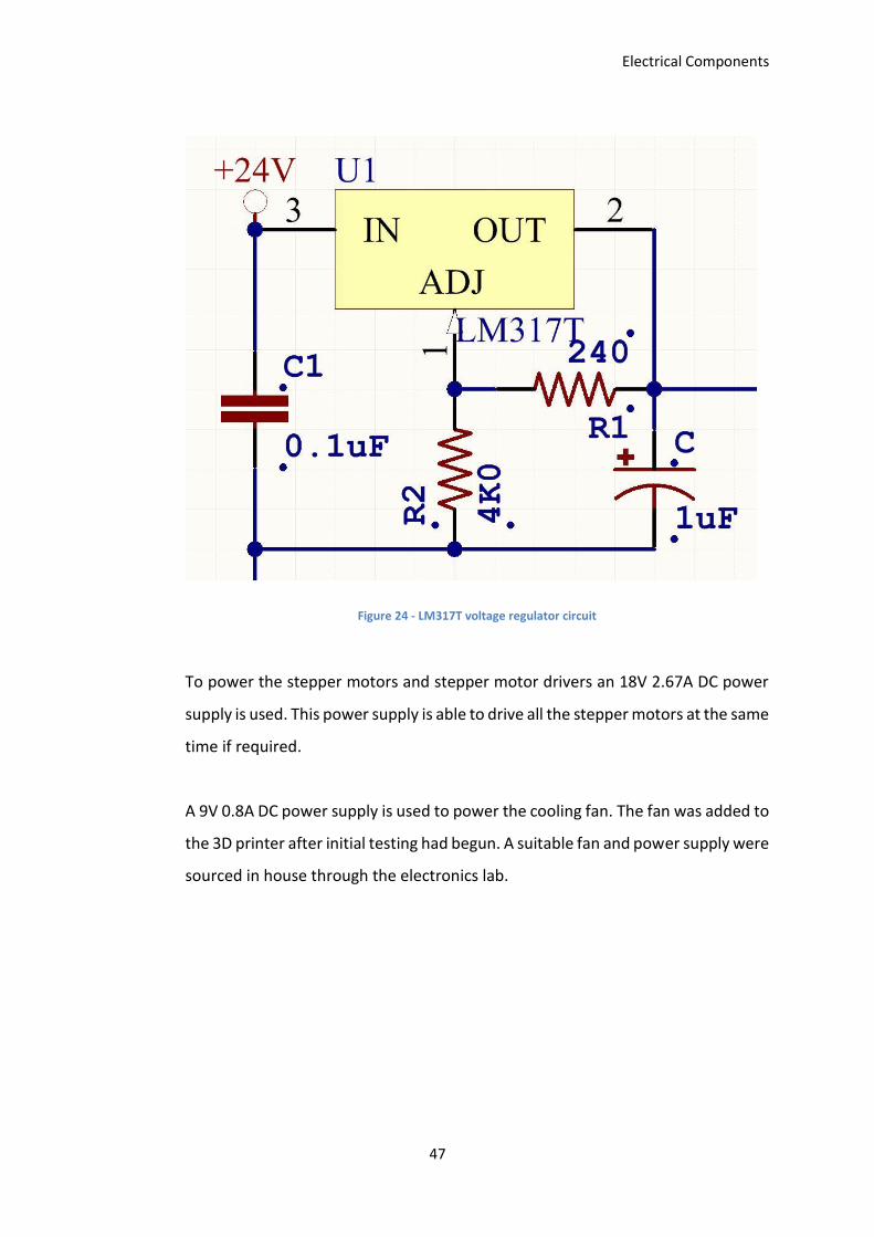
The Darlington Arrays, and subsequently the print head, are powered with a 24V
2.0A DC power supply. This power supply is connected to an LM317T voltage
regulator circuit (Figure 24). This circuit regulates the voltage to 22.08V, a suitable
level for the print head signals through the Darlington Arrays. The formula for the
output voltage from the LM317T is:
𝑉𝑜𝑢𝑡 = 1.25𝑉 ∗ (1 +𝑅1
𝑅2)
To achieve the desired voltage of 22V, a 240Ω resistor is used for R1, and a 4kΩ
resistor is used for R2 (STMicroelectronics, N.D.-a).
Electrical Components
47
Figure 24 - LM317T voltage regulator circuit
To power the stepper motors and stepper motor drivers an 18V 2.67A DC power
supply is used. This power supply is able to drive all the stepper motors at the same
time if required.
A 9V 0.8A DC power supply is used to power the cooling fan. The fan was added to
the 3D printer after initial testing had begun. A suitable fan and power supply were
sourced in house through the electronics lab.
Electrical Components
48
4.7 Prototyping Electronics
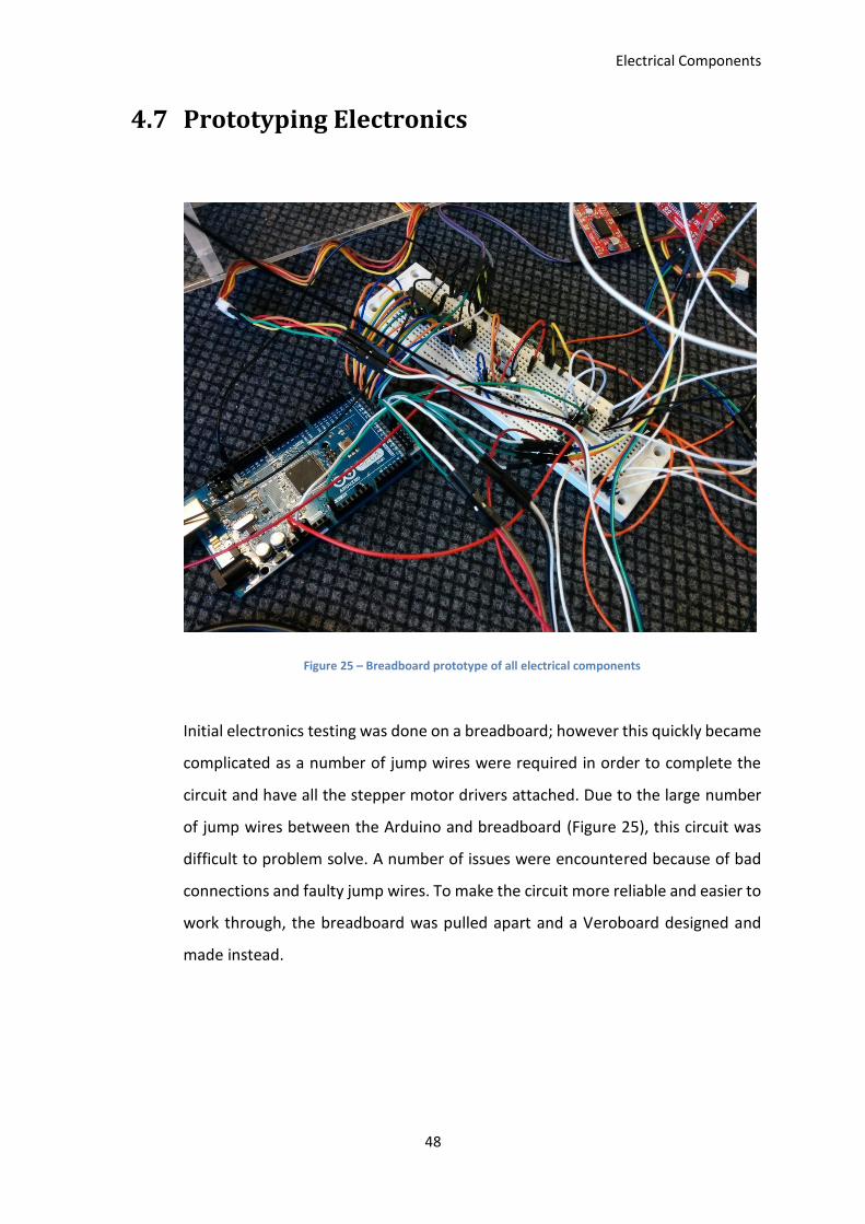
Figure 25 – Breadboard prototype of all electrical components
Initial electronics testing was done on a breadboard; however this quickly became
complicated as a number of jump wires were required in order to complete the
circuit and have all the stepper motor drivers attached. Due to the large number
of jump wires between the Arduino and breadboard (Figure 25), this circuit was
difficult to problem solve. A number of issues were encountered because of bad
connections and faulty jump wires. To make the circuit more reliable and easier to
work through, the breadboard was pulled apart and a Veroboard designed and
made instead.
Electrical Components
49
4.8 Veroboard Prototyping
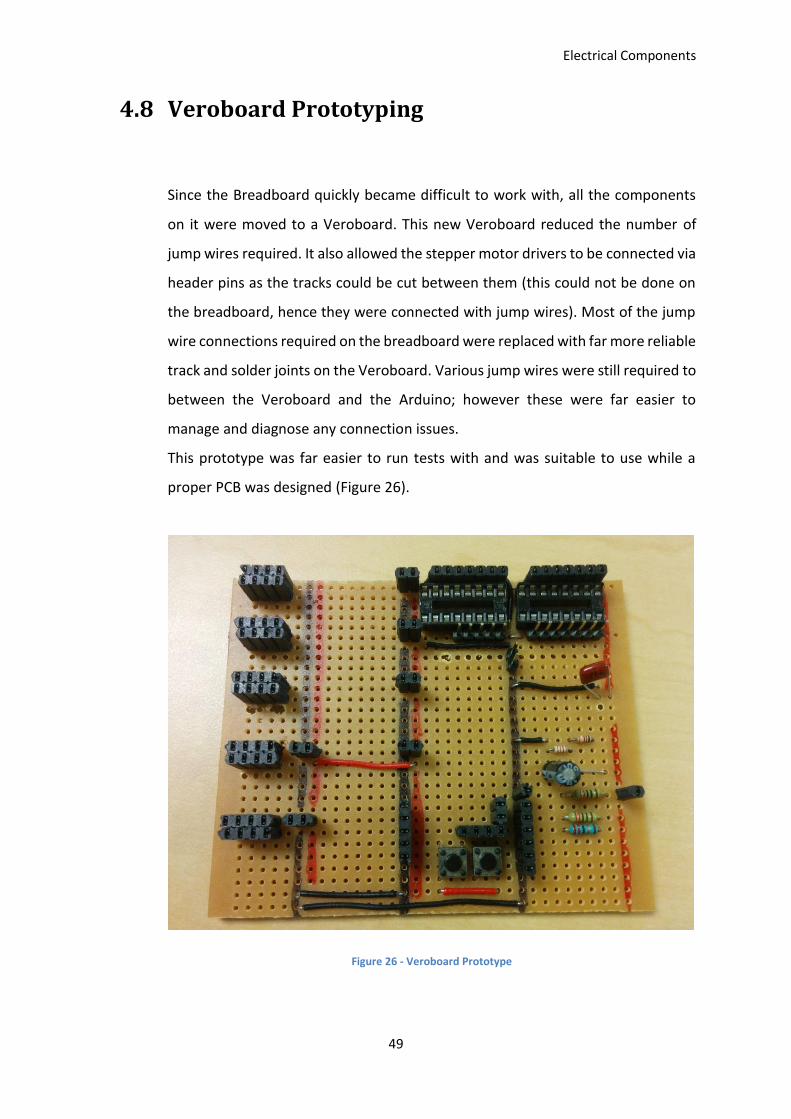
Since the Breadboard quickly became difficult to work with, all the components
on it were moved to a Veroboard. This new Veroboard reduced the number of
jump wires required. It also allowed the stepper motor drivers to be connected via
header pins as the tracks could be cut between them (this could not be done on
the breadboard, hence they were connected with jump wires). Most of the jump
wire connections required on the breadboard were replaced with far more reliable
track and solder joints on the Veroboard. Various jump wires were still required to
between the Veroboard and the Arduino; however these were far easier to
manage and diagnose any connection issues.
This prototype was far easier to run tests with and was suitable to use while a
proper PCB was designed (Figure 26).
Figure 26 - Veroboard Prototype
Electrical Components
50
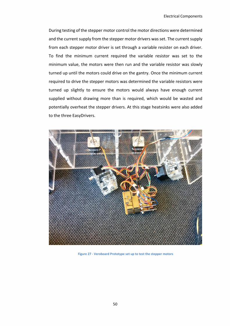
During testing of the stepper motor control the motor directions were determined
and the current supply from the stepper motor drivers was set. The current supply
from each stepper motor driver is set through a variable resister on each driver.
To find the minimum current required the variable resistor was set to the
minimum value, the motors were then run and the variable resistor was slowly
turned up until the motors could drive on the gantry. Once the minimum current
required to drive the stepper motors was determined the variable resistors were
turned up slightly to ensure the motors would always have enough current
supplied without drawing more than is required, which would be wasted and
potentially overheat the stepper drivers. At this stage heatsinks were also added
to the three EasyDrivers.
Figure 27 - Veroboard Prototype set up to test the stepper motors
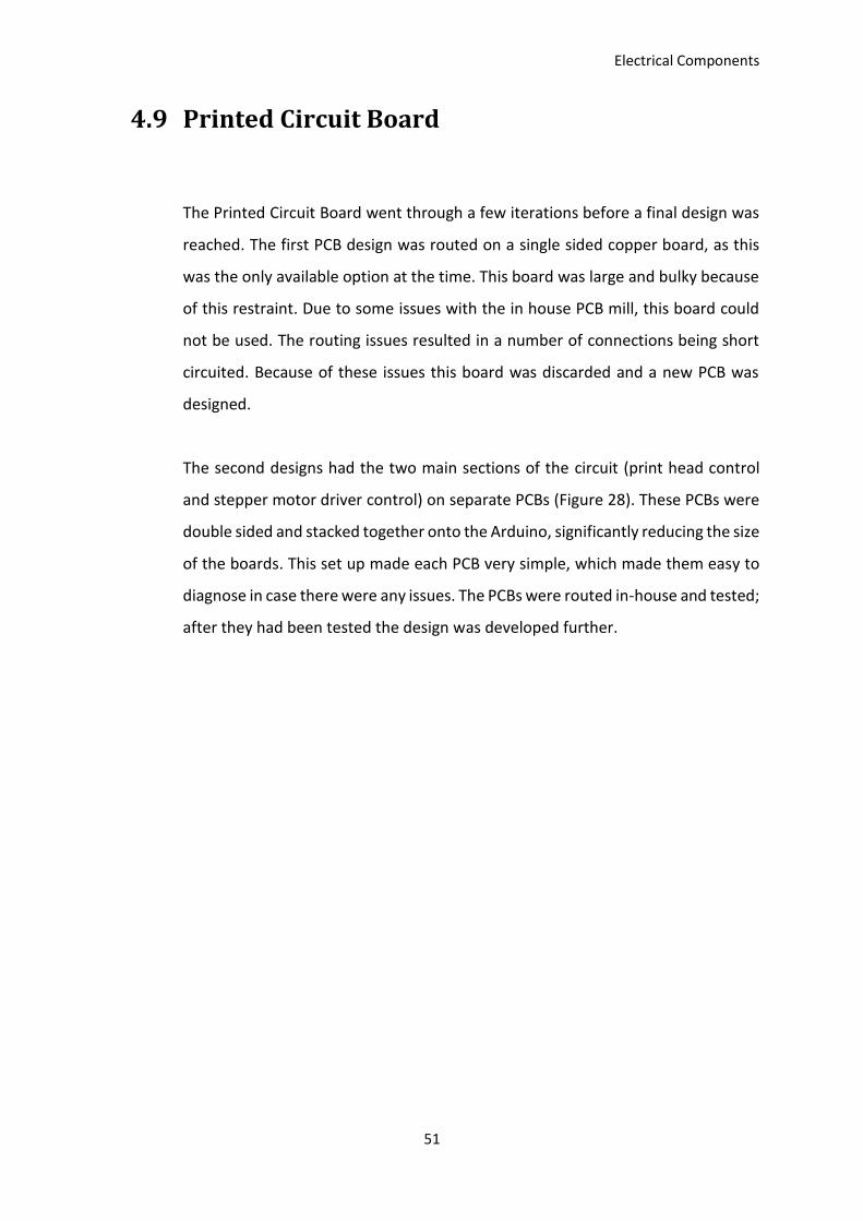
Electrical Components
51
4.9 Printed Circuit Board
The Printed Circuit Board went through a few iterations before a final design was
reached. The first PCB design was routed on a single sided copper board, as this
was the only available option at the time. This board was large and bulky because
of this restraint. Due to some issues with the in house PCB mill, this board could
not be used. The routing issues resulted in a number of connections being short
circuited. Because of these issues this board was discarded and a new PCB was
designed.
The second designs had the two main sections of the circuit (print head control
and stepper motor driver control) on separate PCBs (Figure 28). These PCBs were
double sided and stacked together onto the Arduino, significantly reducing the size
of the boards. This set up made each PCB very simple, which made them easy to
diagnose in case there were any issues. The PCBs were routed in-house and tested;
after they had been tested the design was developed further.
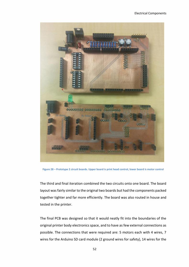
Electrical Components
52
Figure 28 – Prototype 2 circuit boards. Upper board is print head control, lower board is motor control
The third and final iteration combined the two circuits onto one board. The board
layout was fairly similar to the original two boards but had the components packed
together tighter and far more efficiently. The board was also routed in house and
tested in the printer.
The final PCB was designed so that it would neatly fit into the boundaries of the
original printer body electronics space, and to have as few external connections as
possible. The connections that were required are: 5 motors each with 4 wires, 7
wires for the Arduino SD card module (2 ground wires for safety), 14 wires for the
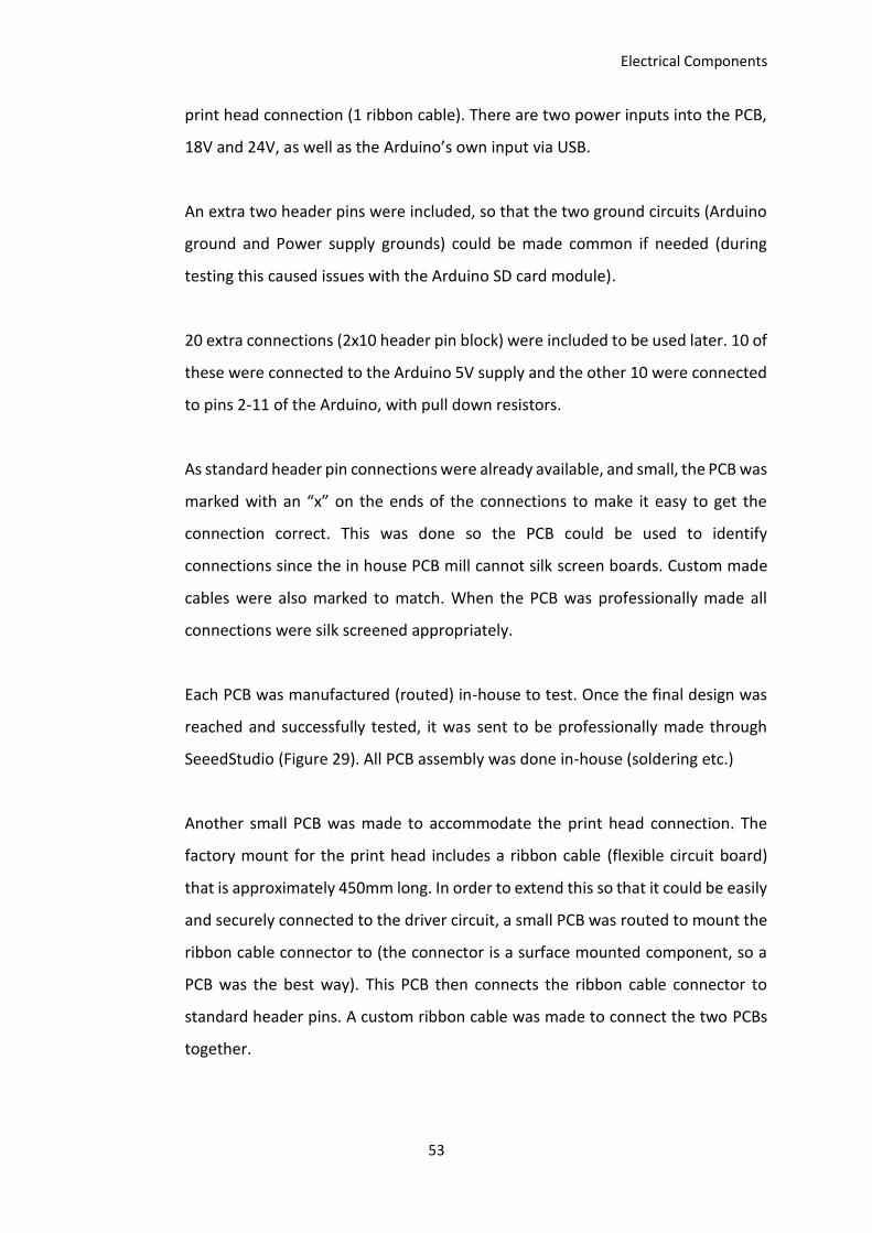
Electrical Components
53
print head connection (1 ribbon cable). There are two power inputs into the PCB,
18V and 24V, as well as the Arduino’s own input via USB.
An extra two header pins were included, so that the two ground circuits (Arduino
ground and Power supply grounds) could be made common if needed (during
testing this caused issues with the Arduino SD card module).
20 extra connections (2x10 header pin block) were included to be used later. 10 of
these were connected to the Arduino 5V supply and the other 10 were connected
to pins 2-11 of the Arduino, with pull down resistors.
As standard header pin connections were already available, and small, the PCB was
marked with an “x” on the ends of the connections to make it easy to get the
connection correct. This was done so the PCB could be used to identify
connections since the in house PCB mill cannot silk screen boards. Custom made
cables were also marked to match. When the PCB was professionally made all
connections were silk screened appropriately.
Each PCB was manufactured (routed) in-house to test. Once the final design was
reached and successfully tested, it was sent to be professionally made through
SeeedStudio (Figure 29). All PCB assembly was done in-house (soldering etc.)
Another small PCB was made to accommodate the print head connection. The
factory mount for the print head includes a ribbon cable (flexible circuit board)
that is approximately 450mm long. In order to extend this so that it could be easily
and securely connected to the driver circuit, a small PCB was routed to mount the
ribbon cable connector to (the connector is a surface mounted component, so a
PCB was the best way). This PCB then connects the ribbon cable connector to
standard header pins. A custom ribbon cable was made to connect the two PCBs
together.

Electrical Components
54
4.10 Chapter Summary
This chapter discussed the electrical components used in the circuit of the
developed 3D printer. In order to keep costs down low cost, open source
components are used. The base of the circuit is an Arduino Mega 2560, which is
an open source development board. The stepper motors are controlled by
SparkFun Easy driver and BigEasy driver stepper motor drivers. These are readily
available and easy to implement. The print head is controlled through a pair of
Darlington Arrays, which are powered through a voltage regulated circuit.
Also covered in this chapter are the prototyping of the circuit and the development
of a Printed Circuit Board. The PCB went through a few iterations that were
manufactured and tested in house before arriving at a final design that was then
manufactured professionally.
Electrical Components
55
Figure 29 - Final PCB design prototype and professionally manufactured PCB

Electrical Components
56
3D Printer Software
57
Chapter 5. 3D Printer Software
In order to be able to use the 3D printer for research, access to print settings is an
important factor. To ensure the software can easily be edited in future if
necessary, open source software has been used. This gives the user the ability to
access or modify any of the print settings as required.
This software reads in an STL (STereoLithography) file, which is a commonly used
file for 3D printing (Chua, Leong, & Lim, 2010). STL files were created by 3D
Systems and are designed to contain surface geometry information of a 3D part
(Burns, 1993).
5.1 Graphic User Interface (GUI)
The open source design already had a working GUI (Graphic User Interface), so
there was no need to create one from scratch, though a few small changes were
made to improve operation of the existing one.
The original GUI required the serial connection (COM port) to be hardcoded. Since
the COM port can change depending on the number of devices connected to the
PC this was changed so that the GUI displays a list of devices. When the GUI is
started, the home page asks for the COM port to be selected. To do this the user
navigates to the connection tab (Figure 30) and then selects the appropriate COM
port from the list.
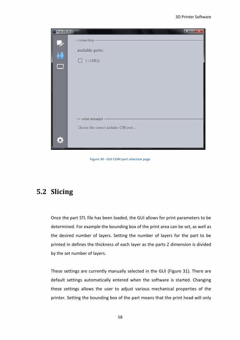
3D Printer Software
58
Figure 30 - GUI COM port selection page
5.2 Slicing
Once the part STL file has been loaded, the GUI allows for print parameters to be
determined. For example the bounding box of the print area can be set, as well as
the desired number of layers. Setting the number of layers for the part to be
printed in defines the thickness of each layer as the parts Z dimension is divided
by the set number of layers.
These settings are currently manually selected in the GUI (Figure 31). There are
default settings automatically entered when the software is started. Changing
these settings allows the user to adjust various mechanical properties of the
printer. Setting the bounding box of the part means that the print head will only
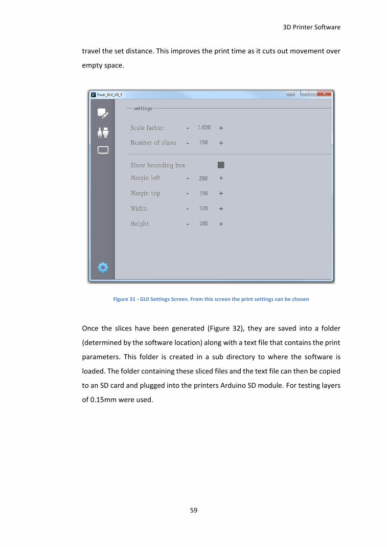
3D Printer Software
59
travel the set distance. This improves the print time as it cuts out movement over
empty space.
Figure 31 - GUI Settings Screen. From this screen the print settings can be chosen
Once the slices have been generated (Figure 32), they are saved into a folder
(determined by the software location) along with a text file that contains the print
parameters. This folder is created in a sub directory to where the software is
loaded. The folder containing these sliced files and the text file can then be copied
to an SD card and plugged into the printers Arduino SD module. For testing layers
of 0.15mm were used.
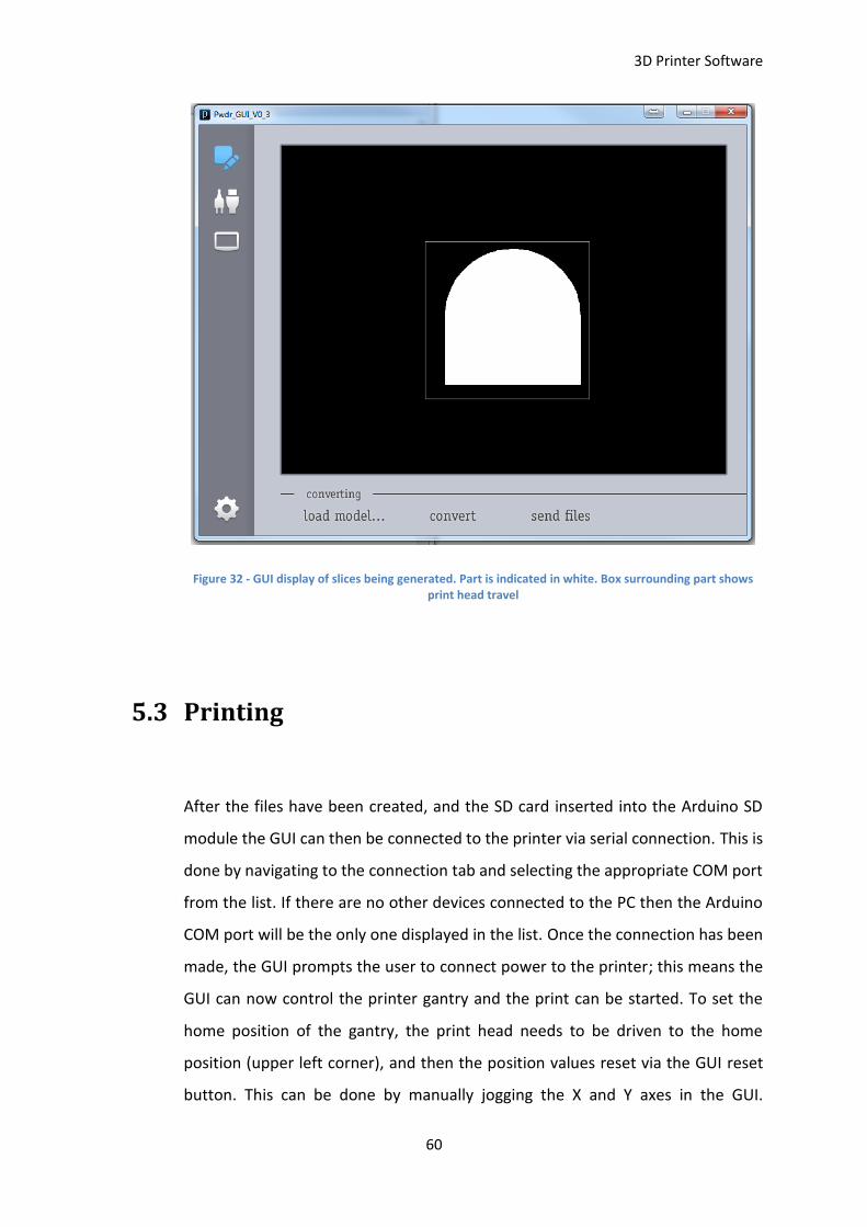
3D Printer Software
60
Figure 32 - GUI display of slices being generated. Part is indicated in white. Box surrounding part shows print head travel
5.3 Printing
After the files have been created, and the SD card inserted into the Arduino SD
module the GUI can then be connected to the printer via serial connection. This is
done by navigating to the connection tab and selecting the appropriate COM port
from the list. If there are no other devices connected to the PC then the Arduino
COM port will be the only one displayed in the list. Once the connection has been
made, the GUI prompts the user to connect power to the printer; this means the
GUI can now control the printer gantry and the print can be started. To set the
home position of the gantry, the print head needs to be driven to the home
position (upper left corner), and then the position values reset via the GUI reset
button. This can be done by manually jogging the X and Y axes in the GUI.
3D Printer Software
61
Alternatively the gantry can be manually positioned before the circuit is powered.
Once the gantry is homed, the print head can be moved to the “initial position”;
this positions the print head within the print area and gives it a starting point. After
all the above steps have been taken, the print can be started.
5.4 Arduino Software
The Arduino Software from the original open source design had most of the
control program done, though some changes needed to be made so that it would
work properly. Since the Arduino has built in Serial Peripheral Interface capabilities
the pins used for the stepper motors and print head controls were reassigned. For
the Arduino Mega 2560 pin 50 is Master In Slave Out, pin 51 is Master Out Slave
In, pin 52 is Serial Clock, and pin 53 is Slave Select.
To accommodate the change of pins, the stepper motor pins were changed to 36
& 37 for the Roller motor, 38 & 39 for the X motor, 40 & 41 for the Y motor, and
42 & 43 for the print piston motor, 44 & 45 for the feed piston motor. The Print
head/Darlington arrays use pins 22-35.
5.5 Chapter Summary
This chapter covers the software used to control the developed 3D printer. The
user loads the 3D print file into the GUI, after which they can select the required
printer settings and then create the sliced files. The sliced files are then saved onto
an SD card and transferred to the 3D printer.

3D Printer Software
62
The Graphic User Interface communicates with the Arduino controller via a serial
connection, this connection allows the user manually control the 3D printer to job
the gantry around or move the Z axes up and down for loading/unloading powder,
as well as to set up a 3D print.

3D Printer Software
63
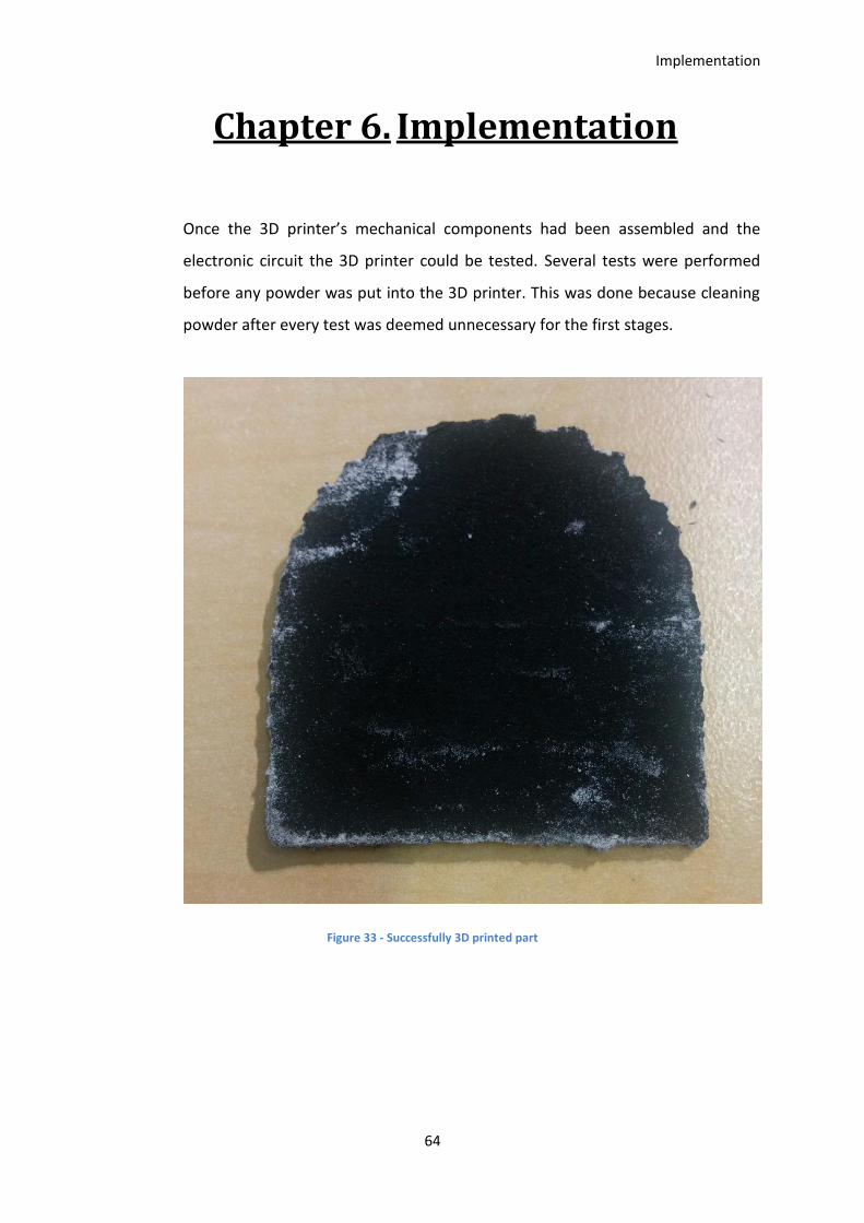
Implementation
64
Chapter 6. Implementation
Once the 3D printer’s mechanical components had been assembled and the
electronic circuit the 3D printer could be tested. Several tests were performed
before any powder was put into the 3D printer. This was done because cleaning
powder after every test was deemed unnecessary for the first stages.
Figure 33 - Successfully 3D printed part
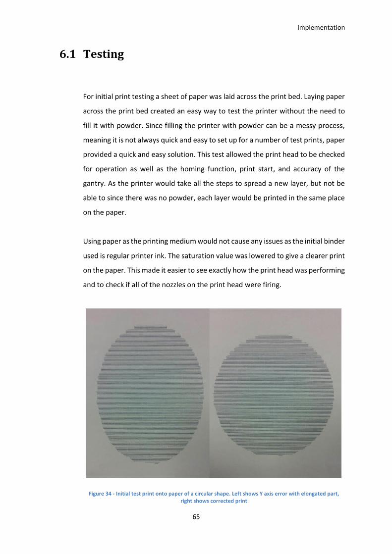
Implementation
65
6.1 Testing
For initial print testing a sheet of paper was laid across the print bed. Laying paper
across the print bed created an easy way to test the printer without the need to
fill it with powder. Since filling the printer with powder can be a messy process,
meaning it is not always quick and easy to set up for a number of test prints, paper
provided a quick and easy solution. This test allowed the print head to be checked
for operation as well as the homing function, print start, and accuracy of the
gantry. As the printer would take all the steps to spread a new layer, but not be
able to since there was no powder, each layer would be printed in the same place
on the paper.
Using paper as the printing medium would not cause any issues as the initial binder
used is regular printer ink. The saturation value was lowered to give a clearer print
on the paper. This made it easier to see exactly how the print head was performing
and to check if all of the nozzles on the print head were firing.
Figure 34 - Initial test print onto paper of a circular shape. Left shows Y axis error with elongated part, right shows corrected print

Implementation
66
The first few tests done were to check the accuracy of the gantry movement.
Different shapes of known dimensions were sliced and printed onto paper for a
single layer, shapes tested included circular, square, and triangular. After the layer
had finished printing the print was cancelled and the shape measured.
The first couple of tests indicated that there was a problem with the Y axis control.
This was clearly shown in the paper test by the circular shape being elongated into
an oval (Figure 34), though the print head swath width appeared to be correct.
The Y axis step size was recalculated in relation to the step spacing for the print
head, and the Arduino software updated. At this stage it was also discovered that
the X and Y axis were not perpendicular to one another, meaning that parts would
not be true. To correct this, the belt on one side of the Y axis was removed; the
gantry was then adjusted until and X and Y axes were perpendicular to one another
and the belt was then put back in place.
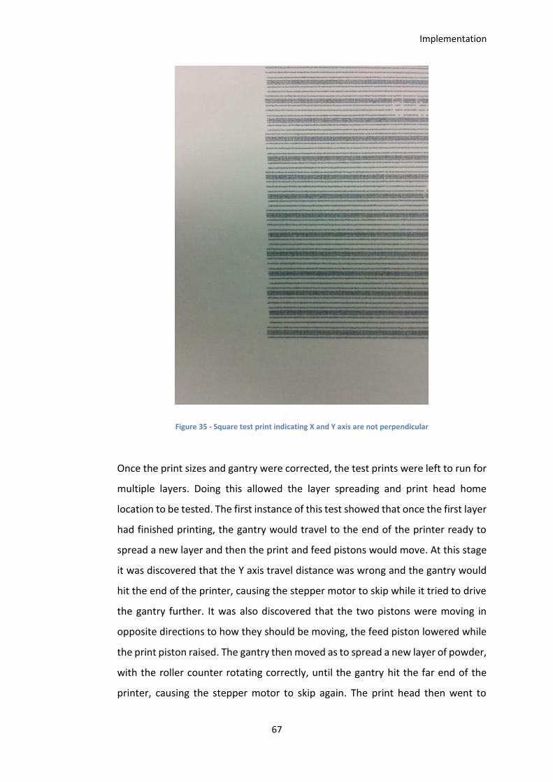
Implementation
67
Figure 35 - Square test print indicating X and Y axis are not perpendicular
Once the print sizes and gantry were corrected, the test prints were left to run for
multiple layers. Doing this allowed the layer spreading and print head home
location to be tested. The first instance of this test showed that once the first layer
had finished printing, the gantry would travel to the end of the printer ready to
spread a new layer and then the print and feed pistons would move. At this stage
it was discovered that the Y axis travel distance was wrong and the gantry would
hit the end of the printer, causing the stepper motor to skip while it tried to drive
the gantry further. It was also discovered that the two pistons were moving in
opposite directions to how they should be moving, the feed piston lowered while
the print piston raised. The gantry then moved as to spread a new layer of powder,
with the roller counter rotating correctly, until the gantry hit the far end of the
printer, causing the stepper motor to skip again. The print head then went to

Implementation
68
return to the part location to print the second layer, though because the stepper
motor had skipped it returned to the wrong place. To correct these issues the
wiring for the feed and print piston motors were swapped, and the Y axis travel
length was adjusted in the code. To find the correct value for the Y axis travel, the
gantry was moved by hand to each end of the printer, and the distance travelled
measured. The number of steps required to travel the full length was then
calculated from this length, as opposed to the overall Y axis length.
Figure 36 - Test print showing print head location issues. Layer 2 can be seen within the first layer
One of the problems during testing was getting all 12 of the nozzles in the print
head firing consistently. Stopping prints halfway through would sometimes cause
blockages in the nozzles. There were a couple of causes for this, during the
prototyping stage there were some connection issues due to loose/faulty jump
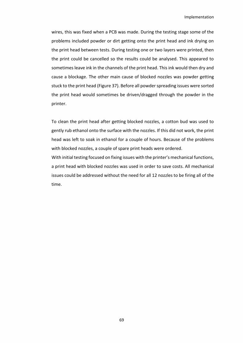
Implementation
69
wires, this was fixed when a PCB was made. During the testing stage some of the
problems included powder or dirt getting onto the print head and ink drying on
the print head between tests. During testing one or two layers were printed, then
the print could be cancelled so the results could be analysed. This appeared to
sometimes leave ink in the channels of the print head. This ink would then dry and
cause a blockage. The other main cause of blocked nozzles was powder getting
stuck to the print head (Figure 37). Before all powder spreading issues were sorted
the print head would sometimes be driven/dragged through the powder in the
printer.
To clean the print head after getting blocked nozzles, a cotton bud was used to
gently rub ethanol onto the surface with the nozzles. If this did not work, the print
head was left to soak in ethanol for a couple of hours. Because of the problems
with blocked nozzles, a couple of spare print heads were ordered.
With initial testing focused on fixing issues with the printer’s mechanical functions,
a print head with blocked nozzles was used in order to save costs. All mechanical
issues could be addressed without the need for all 12 nozzles to be firing all of the
time.
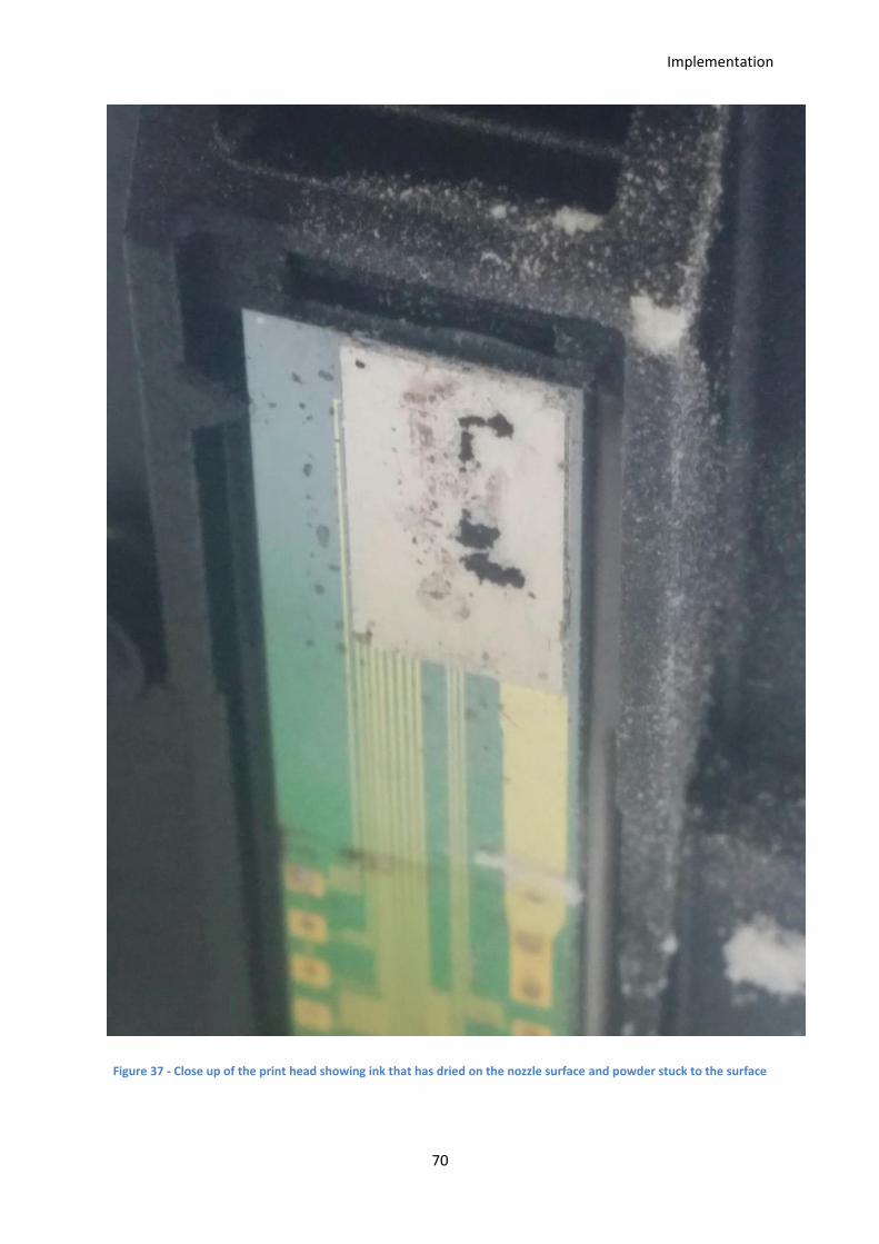
Implementation
70
Figure 37 - Close up of the print head showing ink that has dried on the nozzle surface and powder stuck to the surface
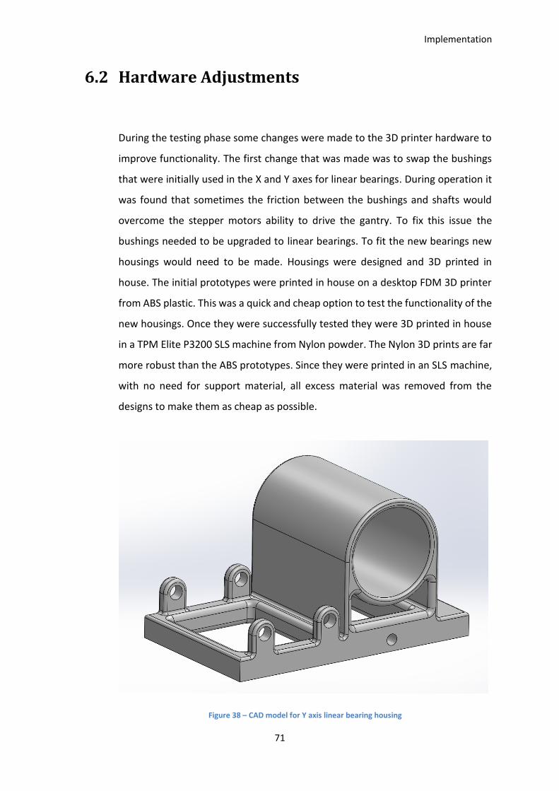
Implementation
71
6.2 Hardware Adjustments
During the testing phase some changes were made to the 3D printer hardware to
improve functionality. The first change that was made was to swap the bushings
that were initially used in the X and Y axes for linear bearings. During operation it
was found that sometimes the friction between the bushings and shafts would
overcome the stepper motors ability to drive the gantry. To fix this issue the
bushings needed to be upgraded to linear bearings. To fit the new bearings new
housings would need to be made. Housings were designed and 3D printed in
house. The initial prototypes were printed in house on a desktop FDM 3D printer
from ABS plastic. This was a quick and cheap option to test the functionality of the
new housings. Once they were successfully tested they were 3D printed in house
in a TPM Elite P3200 SLS machine from Nylon powder. The Nylon 3D prints are far
more robust than the ABS prototypes. Since they were printed in an SLS machine,
with no need for support material, all excess material was removed from the
designs to make them as cheap as possible.
Figure 38 – CAD model for Y axis linear bearing housing
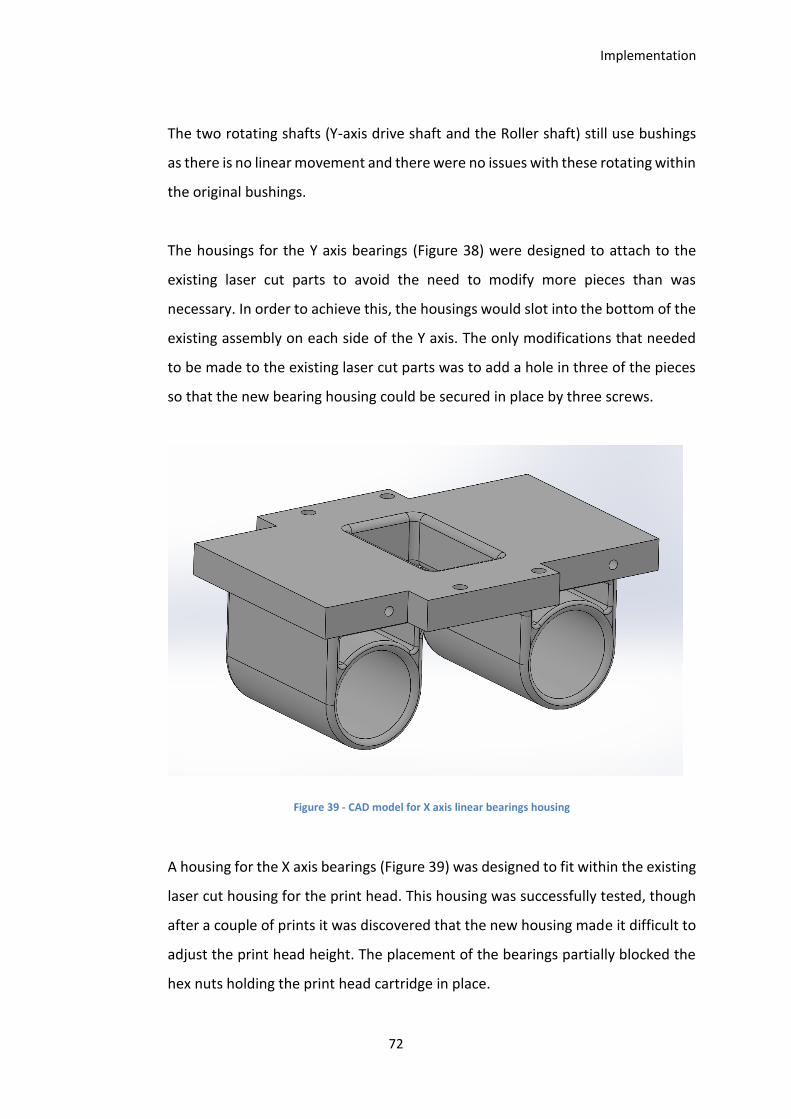
Implementation
72
The two rotating shafts (Y-axis drive shaft and the Roller shaft) still use bushings
as there is no linear movement and there were no issues with these rotating within
the original bushings.
The housings for the Y axis bearings (Figure 38) were designed to attach to the
existing laser cut parts to avoid the need to modify more pieces than was
necessary. In order to achieve this, the housings would slot into the bottom of the
existing assembly on each side of the Y axis. The only modifications that needed
to be made to the existing laser cut parts was to add a hole in three of the pieces
so that the new bearing housing could be secured in place by three screws.
Figure 39 - CAD model for X axis linear bearings housing
A housing for the X axis bearings (Figure 39) was designed to fit within the existing
laser cut housing for the print head. This housing was successfully tested, though
after a couple of prints it was discovered that the new housing made it difficult to
adjust the print head height. The placement of the bearings partially blocked the
hex nuts holding the print head cartridge in place.
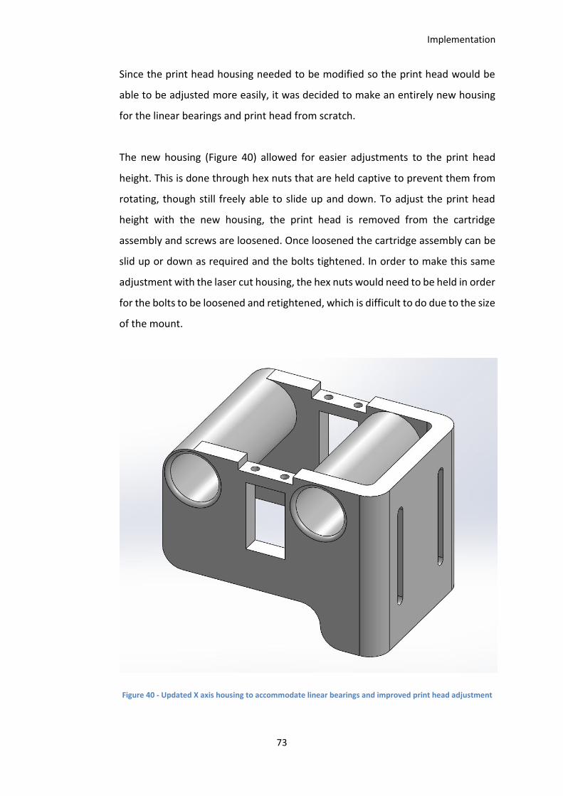
Implementation
73
Since the print head housing needed to be modified so the print head would be
able to be adjusted more easily, it was decided to make an entirely new housing
for the linear bearings and print head from scratch.
The new housing (Figure 40) allowed for easier adjustments to the print head
height. This is done through hex nuts that are held captive to prevent them from
rotating, though still freely able to slide up and down. To adjust the print head
height with the new housing, the print head is removed from the cartridge
assembly and screws are loosened. Once loosened the cartridge assembly can be
slid up or down as required and the bolts tightened. In order to make this same
adjustment with the laser cut housing, the hex nuts would need to be held in order
for the bolts to be loosened and retightened, which is difficult to do due to the size
of the mount.
Figure 40 - Updated X axis housing to accommodate linear bearings and improved print head adjustment

Implementation
74
Small ribs were added along the edge of the Y-axis to prevent powder from tipping
over the edge when spreading a new layer (Figure 41). This was done by laser
cutting strips of acrylic 2mm wide x 3mm thick x 475mm long and gluing them in
place along the edges of the Y axis. The Roller shaft was then turned down at both
ends to fit within the gap between the two raised edges.
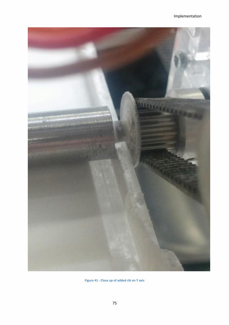
Implementation
75
Figure 41 - Close up of added rib on Y axis
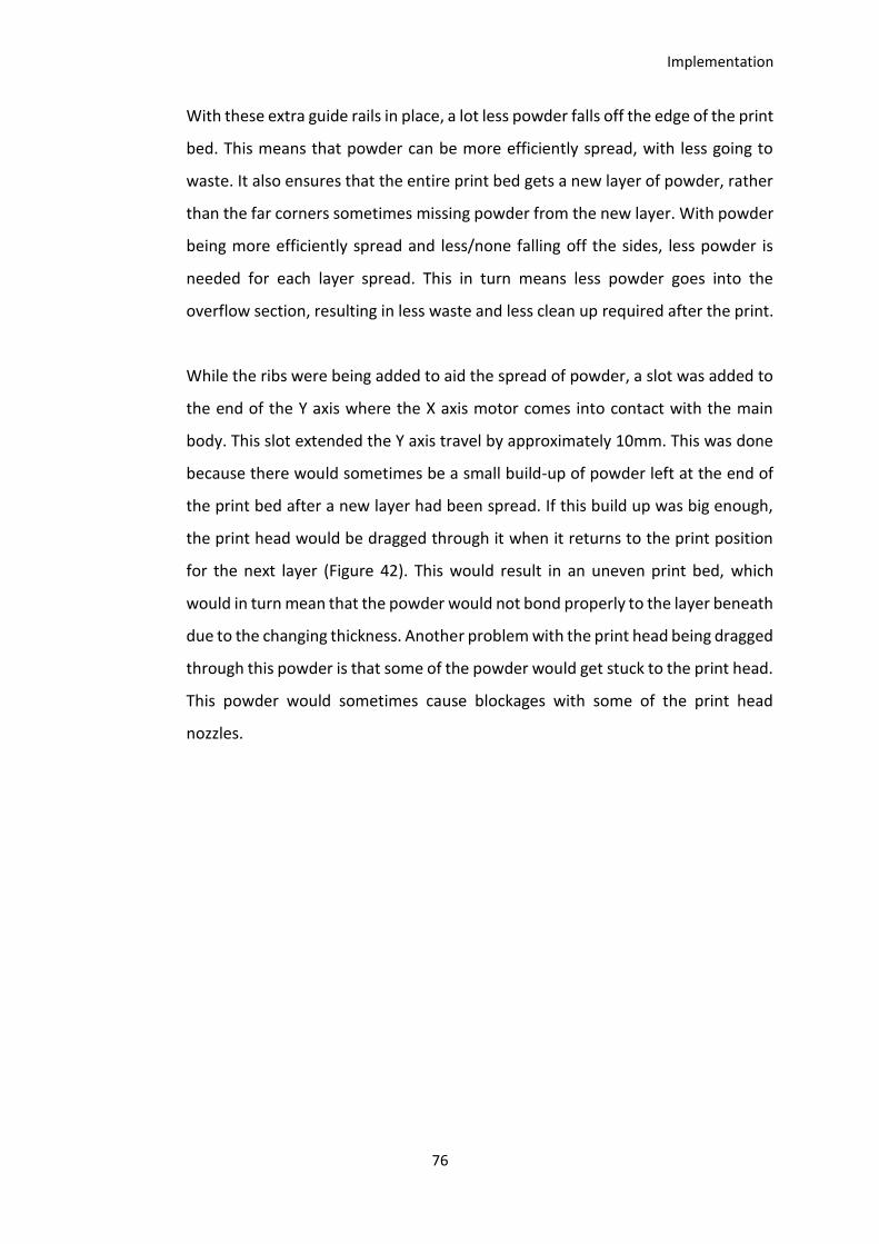
Implementation
76
With these extra guide rails in place, a lot less powder falls off the edge of the print
bed. This means that powder can be more efficiently spread, with less going to
waste. It also ensures that the entire print bed gets a new layer of powder, rather
than the far corners sometimes missing powder from the new layer. With powder
being more efficiently spread and less/none falling off the sides, less powder is
needed for each layer spread. This in turn means less powder goes into the
overflow section, resulting in less waste and less clean up required after the print.
While the ribs were being added to aid the spread of powder, a slot was added to
the end of the Y axis where the X axis motor comes into contact with the main
body. This slot extended the Y axis travel by approximately 10mm. This was done
because there would sometimes be a small build-up of powder left at the end of
the print bed after a new layer had been spread. If this build up was big enough,
the print head would be dragged through it when it returns to the print position
for the next layer (Figure 42). This would result in an uneven print bed, which
would in turn mean that the powder would not bond properly to the layer beneath
due to the changing thickness. Another problem with the print head being dragged
through this powder is that some of the powder would get stuck to the print head.
This powder would sometimes cause blockages with some of the print head
nozzles.

Implementation
77
Figure 42 - Powder build up at the end of the Y axis
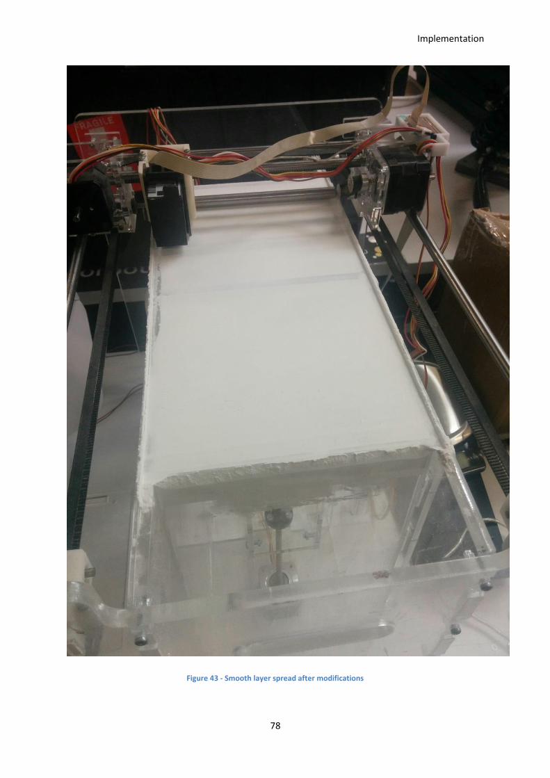
Implementation
78
Figure 43 - Smooth layer spread after modifications
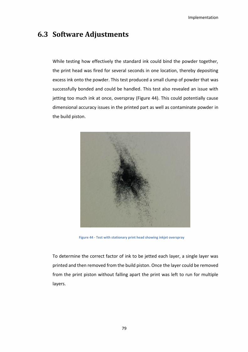
Implementation
79
6.3 Software Adjustments
While testing how effectively the standard ink could bind the powder together,
the print head was fired for several seconds in one location, thereby depositing
excess ink onto the powder. This test produced a small clump of powder that was
successfully bonded and could be handled. This test also revealed an issue with
jetting too much ink at once, overspray (Figure 44). This could potentially cause
dimensional accuracy issues in the printed part as well as contaminate powder in
the build piston.
Figure 44 - Test with stationary print head showing inkjet overspray
To determine the correct factor of ink to be jetted each layer, a single layer was
printed and then removed from the build piston. Once the layer could be removed
from the print piston without falling apart the print was left to run for multiple
layers.
Implementation
80
Figure 45 - Single printed layer partially bonded
Each layer is printed twice before a new layer of powder is spread. This is to ensure
the binder penetrates the powder enough without having too much overspray
from jetting too much ink out of the print head at once. With the saturation value
too high it was found that the ink would not dry before a new layer of powder was
spread on top of the recently finished layer. To allow the ink to dry properly, a
delay of 5 seconds was added after the layer is printed for the first time before the
print head passes over to print the layer a second time. A delay was also added
after the second pass of the layer before the new layer is spread to ensure the ink
is dry. These delays successfully allowed the ink to dry enough so that a new layer
of powder would spread without damaging the existing layer.
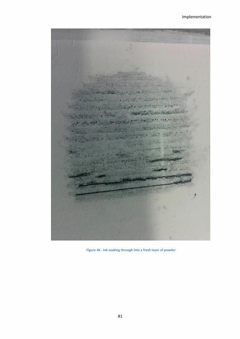
Implementation
81
Figure 46 - Ink soaking through into a fresh layer of powder

Implementation
82
6.4 Chapter Summary
This chapter discussed implementation and testing phase of the project. Discussed
are some of the issues that were encountered with evenly spreading layers of
powder as well as accurately depositing and binding the powder.
The testing process undertaken to discover these problems has been discussed, as
well as the hardware solutions to fix the issues.
Also covered are the software adjustments that were made to allow the binding
process to work successfully. The amount of ink deposited on the powder as well
as the amount of time for the ink to dry were tested and adjusted until a working
solution was found.

Implementation
83
Results and Discussion
84
Chapter 7. Results and Discussion
7.1 Investigate the current state of 3D printing
technology, including currently available low
cost 3D printers and the current state of 3D
printing in the Automotive industry.
As discussed in Chapter 2, 3D printing technologies are well established in a variety
of machines ranging from large scale commercial 3D printers to small, desktop
sized 3D printers for the hobbyist market.
There are a number of FDM 3D printers available at a low cost, with a large portion
of them priced under US$2000. As well as the available low cost FDM 3D printers
there are several low cost SLA 3D printers suitable for hobbyist use, as well as some
other 3D printing technologies emerging in the hobbyist market
At the commercial end of the 3D printing industry there is a large range of 3D
printers that offer a wide range of materials. Some of the available commercial 3D
printers use inkjet technology to produce parts for a range of purposes, including
metal parts, cast-able moulds, and full colour models.
The Automotive industry widely uses 3D printing technologies for prototyping new
designs as well as producing parts used in their vehicles. 3D printing has been used
in the automotive industry for a number of years and has helped to revolutionise
the development process for manufacturers. It has allowed them to improve part
designs faster, and at a much lower cost.
Results and Discussion
85
Recent technology has allowed small scale manufacturers to use functional 3D
printed parts in the cars at a viable cost compared to traditional manufacturing
methods.
Some automotive companies use large scale inkjet 3D printers to produce casting
moulds for their foundries to speed up the manufacturing process. Using these 3D
printers allows them to produce more complex shapes for the casting process.
Using this technology has enabled the automotive industry to develop and
manufacture higher quality parts at a much faster rate. This has enabled them to
bring new designs to market faster and at a lower overall cost.
7.2 Investigate the applications of inkjet printing
technology with 3D printing
Inkjet printing technology has been implemented in a number of commercial 3D
printers in a variety of ways. The main uses of inkjet printing technology in
commercial machines are material jetting or binder jetting style 3D printers. These
3D printers use inkjet style print heads to eject the part material onto a print bed.
The materials printed in these machines are usually wax and UV cured plastics and
rubbers. The other main style of 3D printer that utilises inkjet printing technology
uses the print head to deposit a binder material onto a powder print bed. These
3D printers are usually used to produce sand parts that can be used for metal
casting or full colour plaster/sandstone type models.
Existing commercial 3D printers that use inkjet technology are large and
expensive. They are designed to use proprietary materials and therefore they do
not allow much control to adjust printing parameters, meaning it is difficult to
Results and Discussion
86
experiment with materials and binders. Due to these factors it is not viable to use
one of these commercial 3D printers for research purposes.
7.3 Develop a low cost, powder based 3D printer
using ink-jet printing technology
The developed 3D printer uses a standard drop-on-demand inkjet print head to
deposit a binder onto a powder bed. The tested configuration uses an HP C6602A
print head filled with regular black printer ink deposited onto a bed of VisiJet PXL
core powder. This powder was donated for the project and is a 3D Systems product
used in their ProJet CJP range of inkjet 3D printers.
The total cost to build and develop the 3D printer came in under NZ$2000 for
parts. See Appendix C for a full Bill of Materials breakdown.

Results and Discussion
87
Figure 47 - Final CAD Design
The 3D printer is controlled through an Arduino Mega 2560, a cheap open source
development platform that allows for changes to be made easily. The electronic
circuits and PCB have been developed to use cheap, readily available parts.
Custom parts were 3D printed using the in house FDM and SLS 3D printers.
With these developments done in house, all aspects of the 3D printer can be
adjusted easily. With full control over printer parameters the developed 3D printer
can be used for research into 3D printable materials and binders.
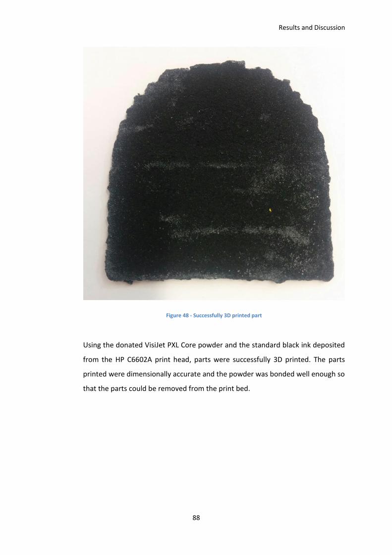
Results and Discussion
88
Figure 48 - Successfully 3D printed part
Using the donated VisiJet PXL Core powder and the standard black ink deposited
from the HP C6602A print head, parts were successfully 3D printed. The parts
printed were dimensionally accurate and the powder was bonded well enough so
that the parts could be removed from the print bed.
Results and Discussion
89
7.4 Design future capability into the printer
hardware
The 3D printer has been developed so that it can be easily modified for research
purposes. With the motor control and print head control using separate power
supplies, one can easily be modified without affecting the other.
The Arduino Mega 2560 used to control the 3D printer has a number of unused
input/output pins that could be used to control any additional components to
increase the capability of the 3D printer.
Extra pins on the Arduino were included into the PCB design with pull down
resistors so that they can be implemented easily to add additional functionality to
the 3D printer.
Conclusion
90
Chapter 8. Conclusion
The 3D printing industry is a rapidly growing space with new emerging
technologies and machines being released often. This research has investigated
the current state of 3D printing technology, including currently available low cost
3D printers and the state of 3D printing in the automotive industry. With the
knowledge gained from this research a 3D printer has been developed to further
the research capabilities in the area.
The 3D printer was developed to utilise inkjet printing technology to produce 3D
parts. The drop-on-demand print head, an HP C6602A print head, deposits regular
black printer ink as a binder onto a powder bed. The powder used in the 3D printer
for this project is a 3D Systems powder known as VisiJet PXL Core, used in their
ProJet CJP range of 3D printers.
Existing commercial 3D printers that utilise inkjet printing technology are not
suitable for research purposes as they are large and expensive. This project
developed a 3D printer that is suitable for research purposes. All parameters of
the printing function can be adjusted to allow experimental research into 3D
printable powders and binders to be conducted. The developed 3D printers uses
less than NZ$2000 in parts and can easily be replicated as well as modified in
house, allowed it to be used for multiple research purposes.

Conclusion
91
References
92
Chapter 9. References
3ders. (2012). VXC800: World's first 3D continuous printer. 2016, from
http://www.3ders.org/articles/20121030-vxc800-world-first-3d-continuous-
printer.html
3DHubs. (2016). 3D Printer Guide. 2016, from https://www.3dhubs.com/best-3d-printer-
guide
3DSystems. (N.D.-a). Colourjet Printers. 2016, from
http://www.3dsystems.com/sites/www.3dsystems.com/files/cjp_specsheet_0416_u
sen_web.pdf
3DSystems. (N.D.-b). ProJet CJP 660Pro. 2016, from http://www.3dsystems.com/3d-
printers/professional/projet-660pro
3DSystems. (N.D.-c). ProJet MJP 5500X. 2016, from
http://www.3dsystems.com/sites/www.3dsystems.com/files/mjp_5500x_specsheet
_usen.pdf
3DSystems. (N.D.-d). Technical User Guide ProX100. User Manual.
3DSystems. (N.D.-e). What is MJP (Multijet Printing). 2016, from
http://www.3dsystems.com/resources/information-guides/multi-jet-printing/mjp
Ainsley, C., Reis, N., & Derby, B. (2002). Freeform fabrication by controlled droplet deposition
of powder filled melts. Journal of materials science, 37(15), 3155-3161.
Allegro. (N.D.-a). DMOS Microstepping Driver with Translator And Overcurrent Protection.
2015, from https://cdn.sparkfun.com/datasheets/Robotics/A4988-Datasheet.pdf
Allegro. (N.D.-b). Microstepping Driver with Translator - A3967. from
https://cdn.sparkfun.com/datasheets/Robotics/A3967-Datasheet.pdf
Arduino. (N.D.). Arduino Mega. 2016, from
https://www.arduino.cc/en/Main/arduinoBoardMega
Blazdell, P., & Evans, J. (2000). Application of a continuous ink jet printer to solid freeforming
of ceramics. Journal of Materials Processing Technology, 99(1), 94-102.
Bunkley, N. (2014). Auto industry uses 3-D printing heavily in product development.
Retrieved 2016, from
References
93
http://www.autonews.com/article/20141027/OEM06/310279987/auto-industry-
uses-3-d-printing-heavily-in-product-development
Burns, M. (1993). Automated fabrication: improving productivity in manufacturing: Prentice-
Hall, Inc.
Chua, C. K., Leong, K. F., & Lim, C. S. (2010). Rapid prototyping: principles and applications:
World Scientific.
Cleary, N. (2016). HP jumps into 3D printing with Multi Jet Fusion printers. 2017, from
http://www.disruptivemagazine.com/features/hp-jumps-3d-printing-multi-jet-
fusion-printers
Derby, B. (2010). Inkjet printing of functional and structural materials: fluid property
requirements, feature stability, and resolution. Annual Review of Materials Research,
40, 395-414.
Derby, B. (2011). Inkjet printing ceramics: from drops to solid. Journal of the European
Ceramic Society, 31(14), 2543-2550.
DesignPoint. (N.D.). 3D Systems – CJP 660Pro & CJP 860Pro. 2016, from http://www.design-
point.com/hardware/3d-systems-cjp660pro-cjp860pro/
DRIVE, T. (2013). Ford 3D Printing - Official Promo. youtube.com: Test DRIVE.
ExOne. (N.D.-a). 3D Printing Services. from http://www.exone.com/Services/3D-Printing-
Services
ExOne. (N.D.-b). Industry Grade Materials. 2016, from
http://www.exone.com/Resources/Materials
ExOne. (N.D.-c). Systems. 2016, from http://www.exone.com/Systems
Fossen, J. (2005). No-Tools prototyping technology saves Ford millions. 2015, from
http://www.ai-
online.com/Adv/Previous/show_issue.php?id=937#sthash.zT4b2pja.xUFrB6HR.dpbs
Goehrke, S. A. (2014). New Details Emerge on the $3,999 Sintratec SLS 3D Printer. from
https://3dprint.com/20602/sintratec-desktop-sls3dprinter/
Grunewald, S. J. (2015). 3D Systems Hits Euromold to Show Off Their Digital Manufacturing
Capabilities. 2016, from https://3dprint.com/96994/3d-systems-hits-euromold/
Haigh, A. (2016). Inkjet Printer History. 2016, from
http://www.castleink.com/category/73/Inkjet-Printers-A-History-Lesson.html
References
94
Hipolite, W. (2014). Voxeljet Introduces New Phenolic-Direct-Binding 3D Printing Method.
2016, from https://3dprint.com/26922/voxeljet-pdb-3d-printing/
HP. (N.D.). HP Jet Fusion 3D Printing Solution. 2017, from
http://www8.hp.com/us/en/pdf/printers/3d-printers/4AA6-4892ENA-P.pdf
i.materialise. (2010). 3D Metal Printing | 3D Printing Technologies. youtube.com:
i.materialise.
Klapman, Z. (2014). Christian von Koenigsegg Explains the Magic Behind The One:1’s Turbos.
from http://www.6speedonline.com/articles/koenigsegg-makes-turbo/
Kodama, H. (1981). Automatic method for fabricating a three‐dimensional plastic model with
photo‐hardening polymer. Review of scientific instruments, 52(11), 1770-1773.
Koenigsegg, C. v. (2014a). The 3D Printed Variable Turbo - /INSIDE KOENIGSEGG.
youtube.com: /DRIVE.
Koenigsegg, C. v. (2014b). 3D Printing: Titanium, Carbon Fiber, & The One:1 - /INSIDE
KOENIGSEGG. youtube.com: /DRIVE.
Krassenstein, B. (2014). Ice1 & Ice9 - First Ever Affordable SLS 3D Printers to Launch on
Kickstarter Next Week by Norge Systems. 3dprint.com.
Lewis, N. C. (N.D.). Inkshield Theory. 2016, from
http://nicholasclewis.com/projects/inkshield/theory/
Martin, G. D., Hoath, S. D., & Hutchings, I. M. (2008). Inkjet printing-the physics of
manipulating liquid jets and drops. Paper presented at the Journal of Physics:
Conference Series.
Maxey, K. (2014). ExOne M-Flex Production Metal 3D Printer. 2016, from
http://www.engineering.com/3DPrinting/3DPrintingArticles/ArticleID/7618/ExOne-
M-Flex-Production-Metal-3D-Printer.aspx
Mearian, L. (2014). Inside Ford's 3D Printing Lab, where thousands of parts are made.
Retrieved 2016, from http://www.computerworld.com/article/2490192/emerging-
technology-inside-ford-s-3d-printing-lab-where-thousands-of-parts-are-made.html
Mills, C. (2015). This Box Turns Any 3D Printer Into A Multi-Color, Multi-Material Marvel. 2016,
from http://gizmodo.com/this-box-turns-any-3-d-printer-into-a-multi-color-mult-
1699332022
References
95
Nanotec. (N.D.-a). Stepping Motor LS4118S1404-T6x2-150. 2015, from
http://www.farnell.com/datasheets/1443954.pdf?_ga=1.148272311.1858161686.14
83491683
Nanotec. (N.D.-b). Stepping Motor ST4209S1006. 2015, from
http://www.farnell.com/datasheets/1714724.pdf?_ga=1.76840341.1858161686.148
3491683
Norge. (2014). Ice1 and Ice9 - The first low budget SLS 3D printers. 2015, from
https://www.kickstarter.com/projects/1812935123/ice1-and-ice9-the-first-low-
budget-sls-3d-printers
RepRap. (2016). Powder Printer Recipes. 2016, from
http://reprap.org/wiki/Powder_Printer_Recipes#Powder_Formulas
Solenicki, D. (2015). Sintratec - World's First Desktop Laser Sinterer. 2016, from
https://www.indiegogo.com/projects/sintratec-world-s-first-desktop-laser-
sinterer#/
STMicroelectronics. (N.D.-a). 1.2V to 37V adjustable voltage regulators - LM317. 2015, from
http://www.farnell.com/datasheets/1815554.pdf?_ga=1.91107866.1858161686.148
3491683
STMicroelectronics. (N.D.-b). Seven Darlington Array - ULN2003. 2015, from
http://www.farnell.com/datasheets/1955910.pdf?_ga=1.81090839.1858161686.148
3491683
Voxeljet. (2013). Continuous 3D printer VXC800 for sand moulds and plastic parts.
youtube.com: Voxeljet.
Voxeljet. (N.D.). 3D Printing System. 2016, from http://www.voxeljet.com/3d-printing-
system/
Wade, S. (2015). Details – Koenigsegg One:1 Exhaust Tailpiece. 2016, from
http://koenigsegg.com/details-koenigsegg-one1-exhaust-tailpiece/
Wohlers, T. T., & Caffrey, T. (2015). Wohlers report 2015: 3D printing and additive
manufacturing state of the industry annual worldwide progress report: Wohlers
Associates.
Yan, X., & Gu, P. (1996). A review of rapid prototyping technologies and systems. Computer-
Aided Design, 28(4), 307-318.
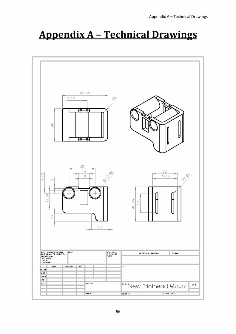
Appendix A – Technical Drawings
96
Appendix A – Technical Drawings
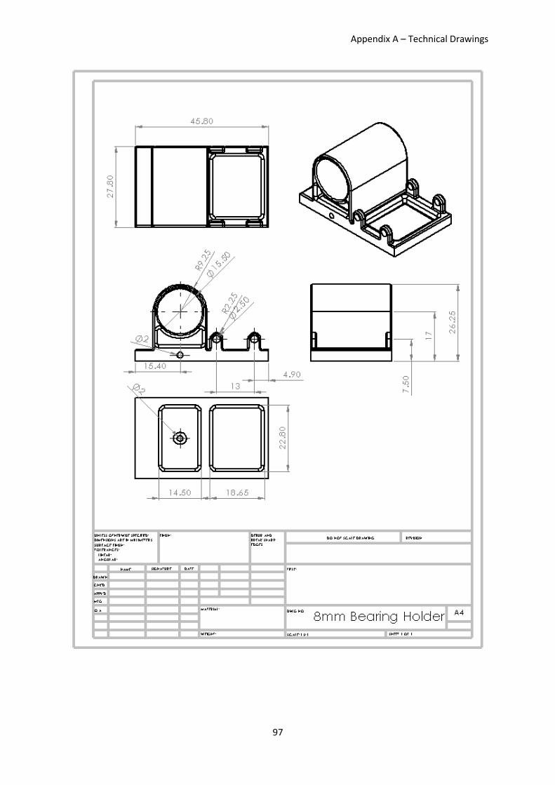
Appendix A – Technical Drawings
97
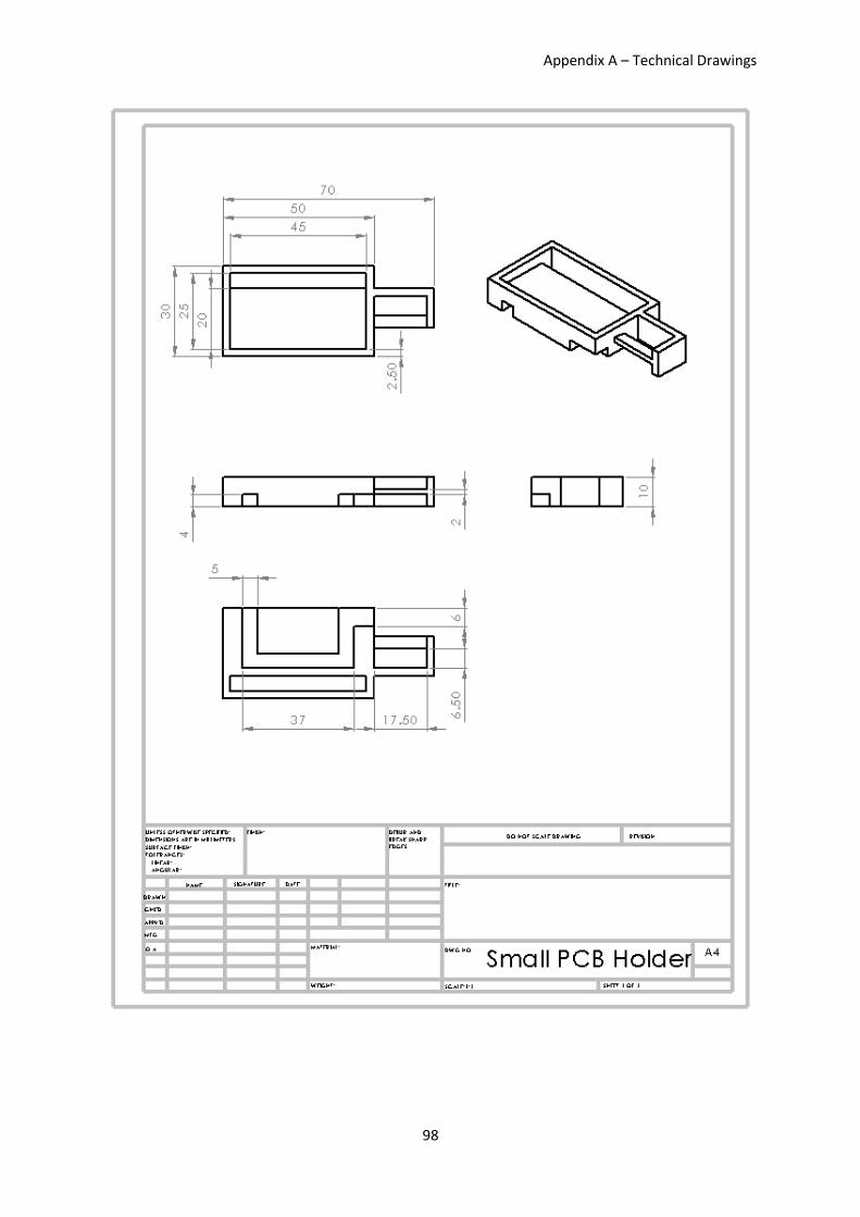
Appendix A – Technical Drawings
98
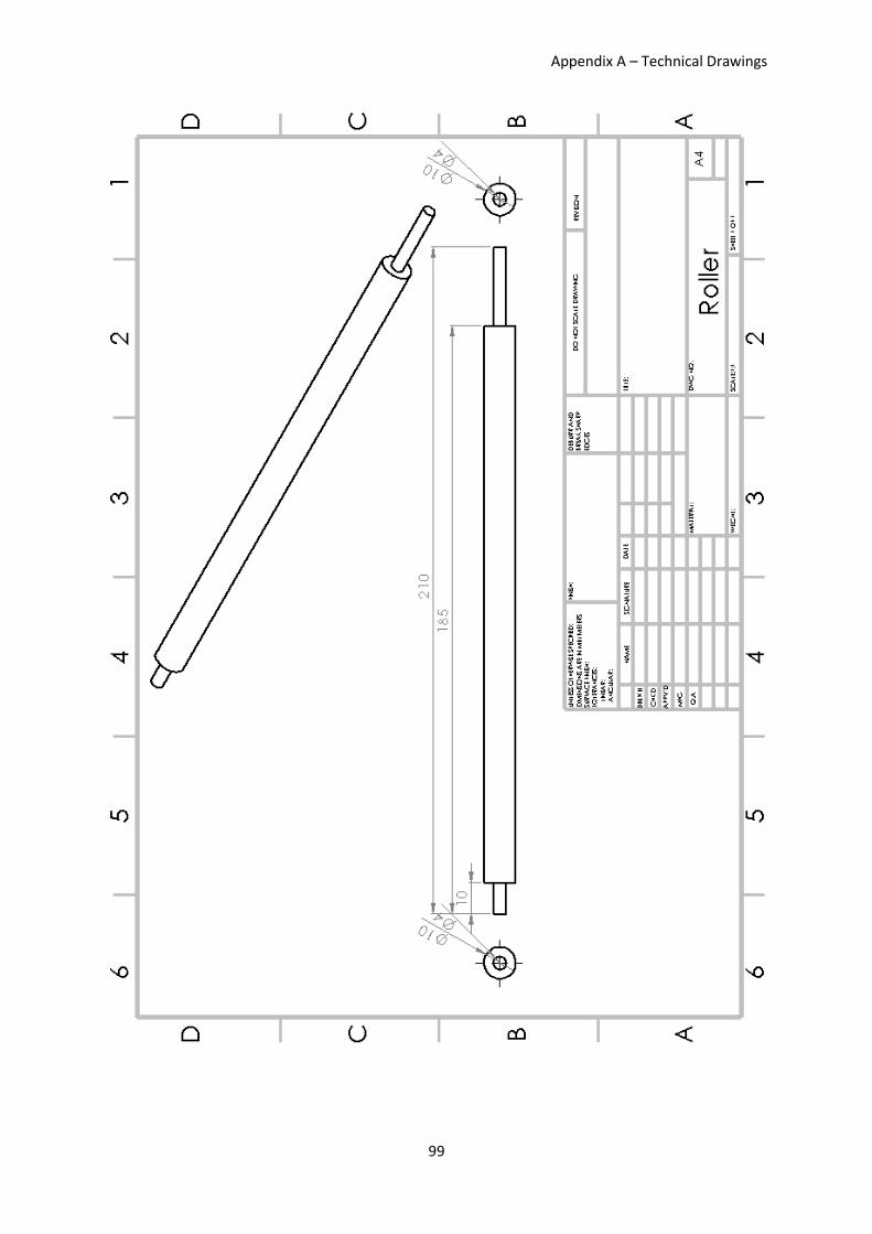
Appendix A – Technical Drawings
99

Appendix A – Technical Drawings
100
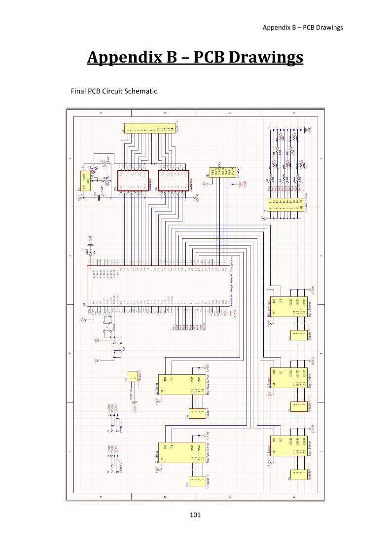
Appendix B – PCB Drawings
101
Appendix B – PCB Drawings
Final PCB Circuit Schematic
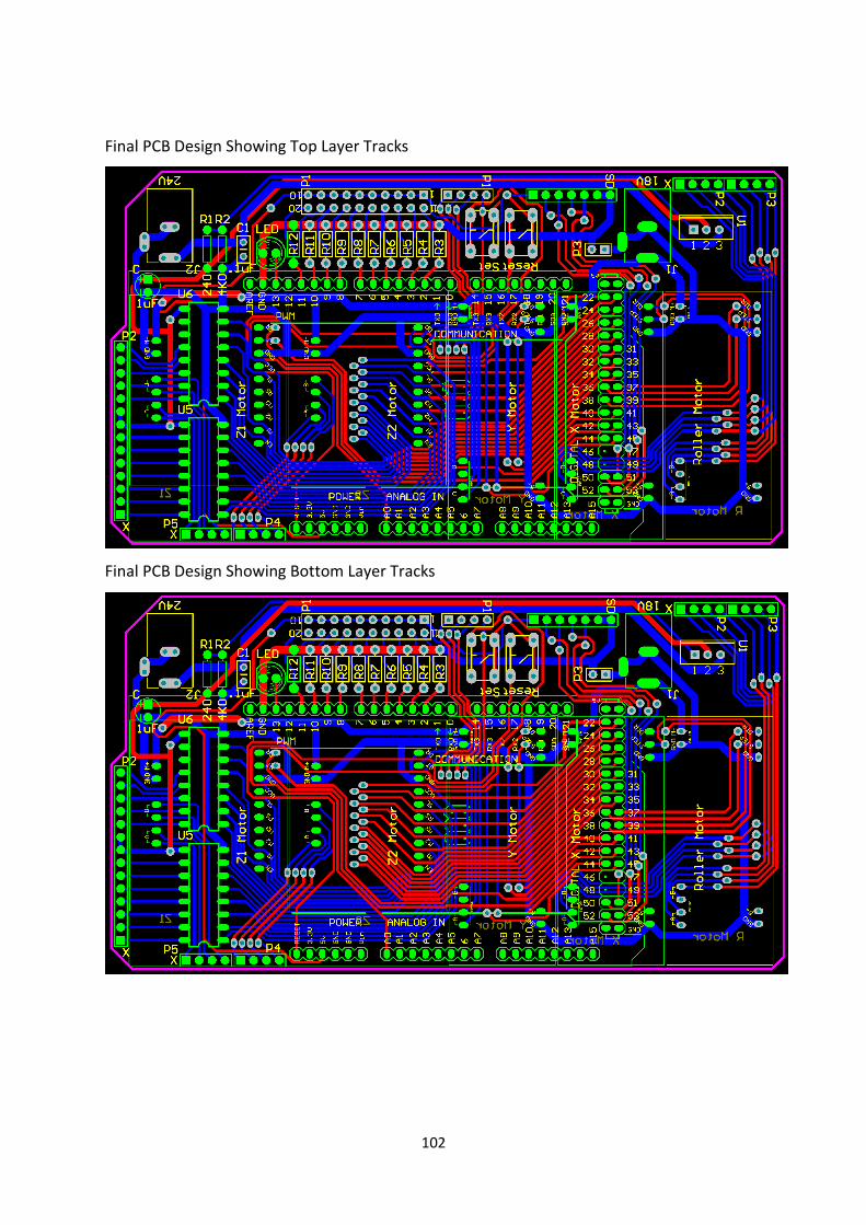
102
Final PCB Design Showing Top Layer Tracks
Final PCB Design Showing Bottom Layer Tracks
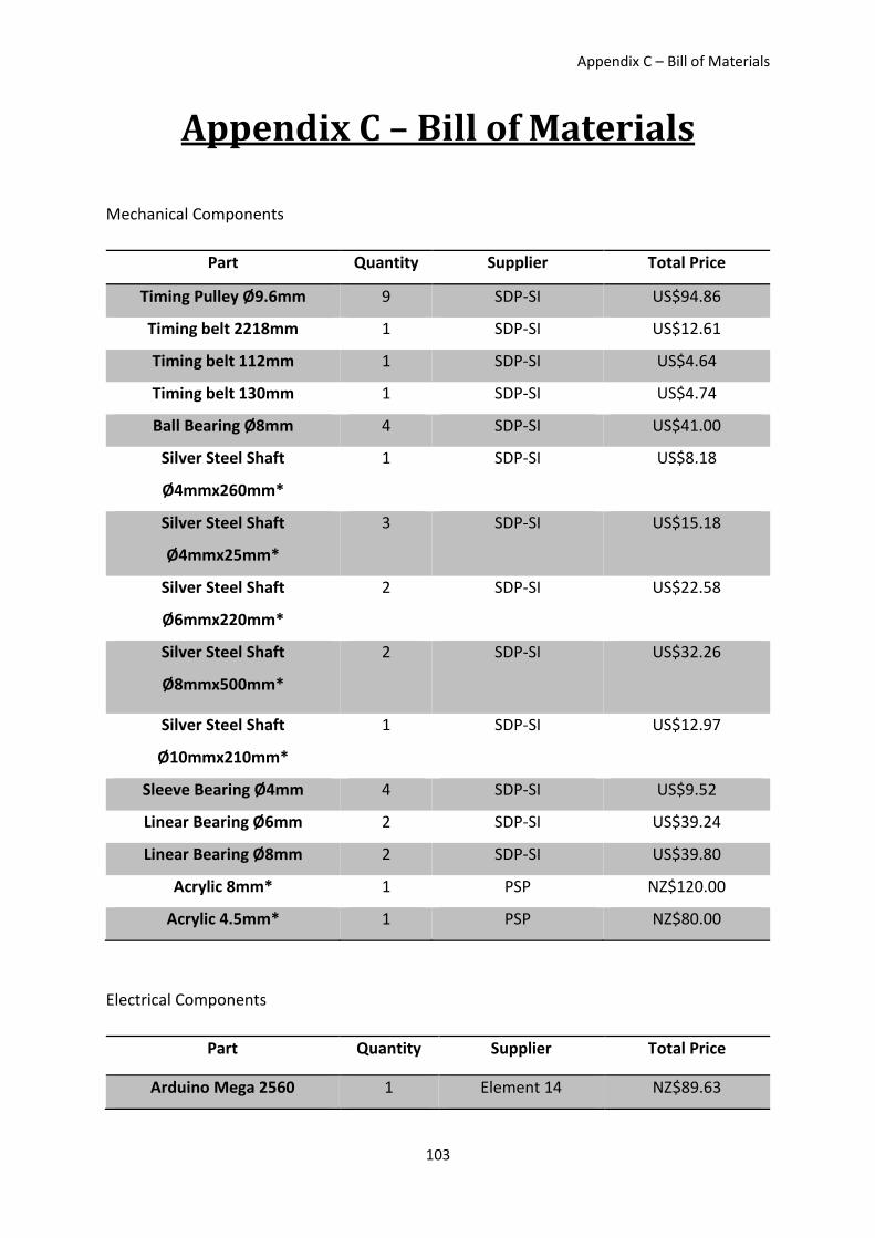
Appendix C – Bill of Materials
103
Appendix C – Bill of Materials
Mechanical Components
Part Quantity Supplier Total Price
Timing Pulley Ø9.6mm 9 SDP-SI US$94.86
Timing belt 2218mm 1 SDP-SI US$12.61
Timing belt 112mm 1 SDP-SI US$4.64
Timing belt 130mm 1 SDP-SI US$4.74
Ball Bearing Ø8mm 4 SDP-SI US$41.00
Silver Steel Shaft
Ø4mmx260mm*
1 SDP-SI US$8.18
Silver Steel Shaft
Ø4mmx25mm*
3 SDP-SI US$15.18
Silver Steel Shaft
Ø6mmx220mm*
2 SDP-SI US$22.58
Silver Steel Shaft
Ø8mmx500mm*
2 SDP-SI US$32.26
Silver Steel Shaft
Ø10mmx210mm*
1 SDP-SI US$12.97
Sleeve Bearing Ø4mm 4 SDP-SI US$9.52
Linear Bearing Ø6mm 2 SDP-SI US$39.24
Linear Bearing Ø8mm 2 SDP-SI US$39.80
Acrylic 8mm* 1 PSP NZ$120.00
Acrylic 4.5mm* 1 PSP NZ$80.00
Electrical Components
Part Quantity Supplier Total Price
Arduino Mega 2560 1 Element 14 NZ$89.63
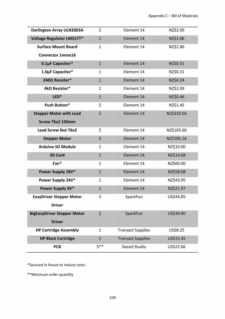
Appendix C – Bill of Materials
104
Darlington Array ULN2003A 2 Element 14 NZ$2.00
Voltage Regulator LM317T* 1 Element 14 NZ$1.06
Surface Mount Board
Connector 1mmx16
1 Element 14 NZ$2.86
0.1µF Capacitor* 1 Element 14 NZ$0.51
1.0µF Capacitor* 1 Element 14 NZ$0.31
240Ω Resistor* 1 Element 14 NZ$0.24
4kΩ Resistor* 1 Element 14 NZ$2.09
LED* 1 Element 14 NZ$0.46
Push Button* 2 Element 14 NZ$1.45
Stepper Motor with Lead
Screw T6x2 150mm
2 Element 14 NZ$310.66
Lead Screw Nut T6x2 2 Element 14 NZ$105.60
Stepper Motor 3 Element 14 NZ$185.16
Arduino SD Module 1 Element 14 NZ$10.00
SD Card 1 Element 14 NZ$14.68
Fan* 1 Element 14 NZ$60.00
Power Supply 18V* 1 Element 14 NZ$58.08
Power Supply 24V* 1 Element 14 NZ$43.95
Power Supply 9V* 1 Element 14 NZ$21.97
EasyDriver Stepper Motor
Driver
3 SparkFun US$44.85
BigEasyDriver Stepper Motor
Driver
2 SparkFun US$39.90
HP Cartridge Assembly 1 Transact Supplies US$8.25
HP Black Cartridge 1 Transact Supplies US$15.45
PCB 5** Seeed Studio US$22.66
*Sourced in house to reduce costs
**Minimum order quantity
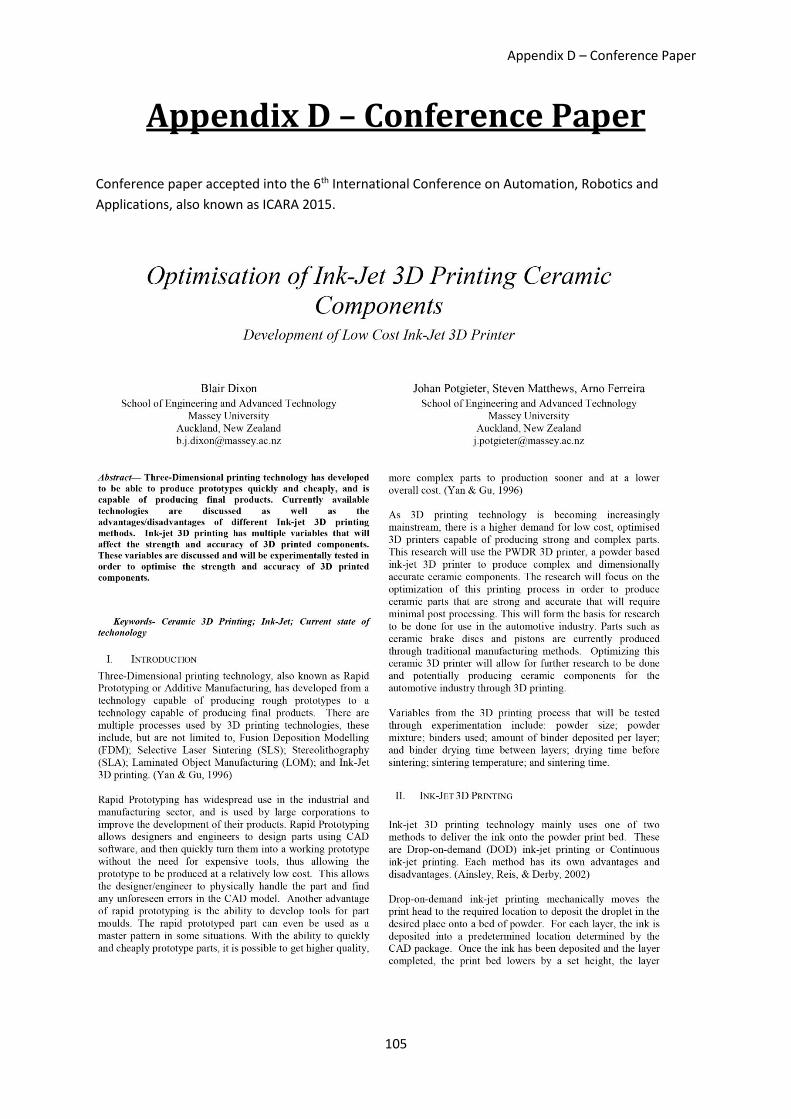
Appendix D – Conference Paper
105
Appendix D – Conference Paper
Conference paper accepted into the 6th International Conference on Automation, Robotics and
Applications, also known as ICARA 2015.
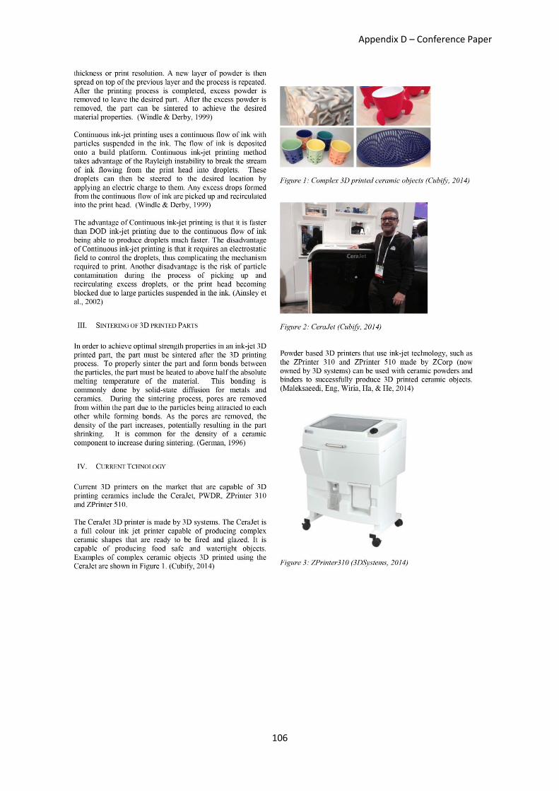
Appendix D – Conference Paper
106
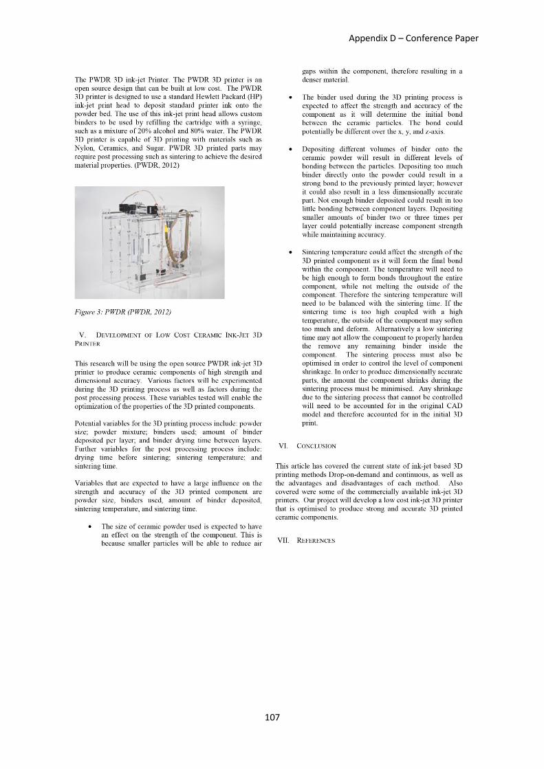
Appendix D – Conference Paper
107
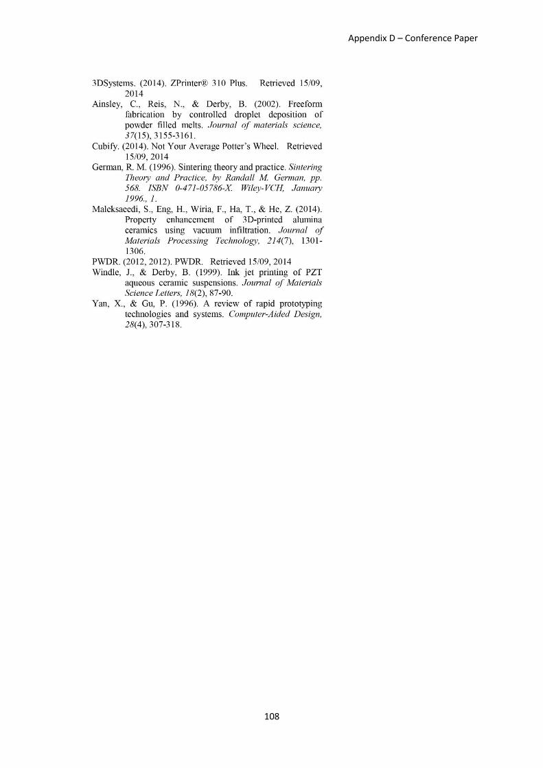
Appendix D – Conference Paper
108