development of materials and systems for ammonia-fueled ... · development of materials and systems...
TRANSCRIPT

Development of Materials and Systems for Ammonia-Fueled Solid Oxide Fuel Cells
Koichi Eguchi (Kyoto University), Yosuke Takahashi (Noritake), Hayahide Yamasaki (Nippon Shokubai), Hidehito Kubo (Toyota Industries), Akihiro Okabe (Mitsui Chemical),
Takenori Isomura (Tokuyama), Takahiro Matsuo (IHI)
NH3 Energy+ -Enabling Optimized, Sustainable Energy and AgricultureAIChEMinneapolis, USA
November 01, 2017,
0

Ammonia as Hydrogen Carrier
H2 density (kg-H2 / m3-liq.)
Boiling point(ºC)
Liquid H2 70.8 –252.6
NH3 120.3 –33.3
C7H14(Methylcyclohexane) 47.1 101.1
High H2 density Carbon-free High boiling point Ease in liquefaction and
transportation Hydrogen production via
decomposition reaction
Table H2 density and boiling point of liquid H2, NH3, andC7H14 (Methylcyclohexane)
NH3 → H2 + N223
21
ΔHº = +46 kJ mol−1
Hydrogen Primary fuel source for
fuel cell Low volume density Difficulty in storage
and transportation
Ammonia

2

3
NH3
H2OO2
O2-
Anode CathodeElectrolyte
e-
N2
Direct ammonia-fueled SOFC
H2 + O2- → H2O + 2 e- 1/2 O2 +2 e- → O2-
2 NH3→ N2 + 3 H2
Hydrogen-fueled SOFC
H2

Kyoto Univ.Hydrogen carrier & energy conversion technology
Ammonia as a promising hydrogen carrier:High H2 density, Carbon-free, Low production cost, High boiling point, Ease in liquefaction and transportation, etc.
0 100 200 300 400 500 600 700
MeOH Hydrocarbons
NH3
PEFC PAFC
Molten Alkali FCAMFC MCFC
SOFC
Temperature (ºC)Fig. Operating temperature ranges of fuel cells and catalytic reformers
Fuel cells
Reforming / decomposition
H2 density (kg-H2 / m3-liq.) Boiling point (ºC) ΔHr (kJ/mol-H2)
Liquid H2 70.8 –252.6 –
NH3 120.3 –33.3 30.62NH3 → N2 +3H2
C7H14(Methylcyclohexane) 47.1 101.1 80.0C7H14 → C7H8 +3H2
4

5
Operation type of ammonia fueled cellR: NH3 decomposition reactor,C:Fuel cell chamber,S:SOFC stack
ExternalDecomposition
NH3
Indirect Internal Decomposition
NH3
Direct Internal Decomposition
NH3
NH3 decomp. reactor installed on the flow line
Optimized operation of each reactor
Large energy loss Large system size Stationary application
Reactor installed in the FC chamber
System design with effective heat management
Either stationary or mobile application
NH3 decomp. reactor unnecessary
NH3decomp. And anode reaction proceed on the electrode
Simplified system Multifunctional electrode Heat management Either stationary or mobile
application

Fig. Time course of ammonia conversion at 515 and 565ºC for the SrO–Ni/Y2O3 catalyst under the stability test at 700ºC with an S.V. of 2,400 h–1.
Durability of Catalyst for NH3 Cracking
Catalyst: 5wt.% SrO–40wt.% Ni/Y2O3 (Pretreated at 600ºC in 50%H2/Ar)Supply gas: 100% NH3; Space velocity = 2,400 h−1
Durability test: 700ºCActivity evaluation: 515ºC, 565ºC

AutothermalNH3 cracking
e-
SOFC
Direct supplyGas in
Gas out
NH3cracking
O2-
Heat
System 3
System 1
System 2
O2-
O2-
O2-
O2-
O2-
e-
e- e-
NH3
NH3NH3
NH3
NH3NH3
NH3
NH3NH3
H2
H2 N2
N2H2O
O2O2
O2O2
O2O2
O2
O2
Ammonia-fueled Solid Oxide Fuel Cell System
It is important to develop the catalystand control the reaction conditions !!
Autothermal NH3 cracking
NH3 + O2 → N2 + H2O 21
23
43
NH3 cracking
NH3 oxidation
NH3 → H2 + N223
21

AutothermalNH3 cracking
e-
SOFC
Direct supplyGas in
Gas out
NH3cracking
O2-
Heat
System 3
System 1
System 2
O2-
O2-
O2-
O2-
O2-
e-
e- e-
NH3
NH3NH3
NH3
NH3NH3
NH3
NH3NH3
H2
H2 N2
N2H2O
O2O2
O2O2
O2O2
O2
O2
Ammonia-fueled Solid Oxide Fuel Cell System
NH3 cracking NH3 → H2 + N22
321
Electrochemical H2 oxidationH2 + O2− → H2O + 2e−

Layer Composition Thickness / µm Diameter / mm
Anode support layer NiO/ZrO2-based material 1000–1100 120
Anode functional layer NiO/ZrO2-based material 7–13 120
Electrolyte layer ZrO2-based material 7–13 120
Cathode layer Perovskite-type oxide material 30–90 110
Table Configuration of the anode-supported cell
Cell & Material
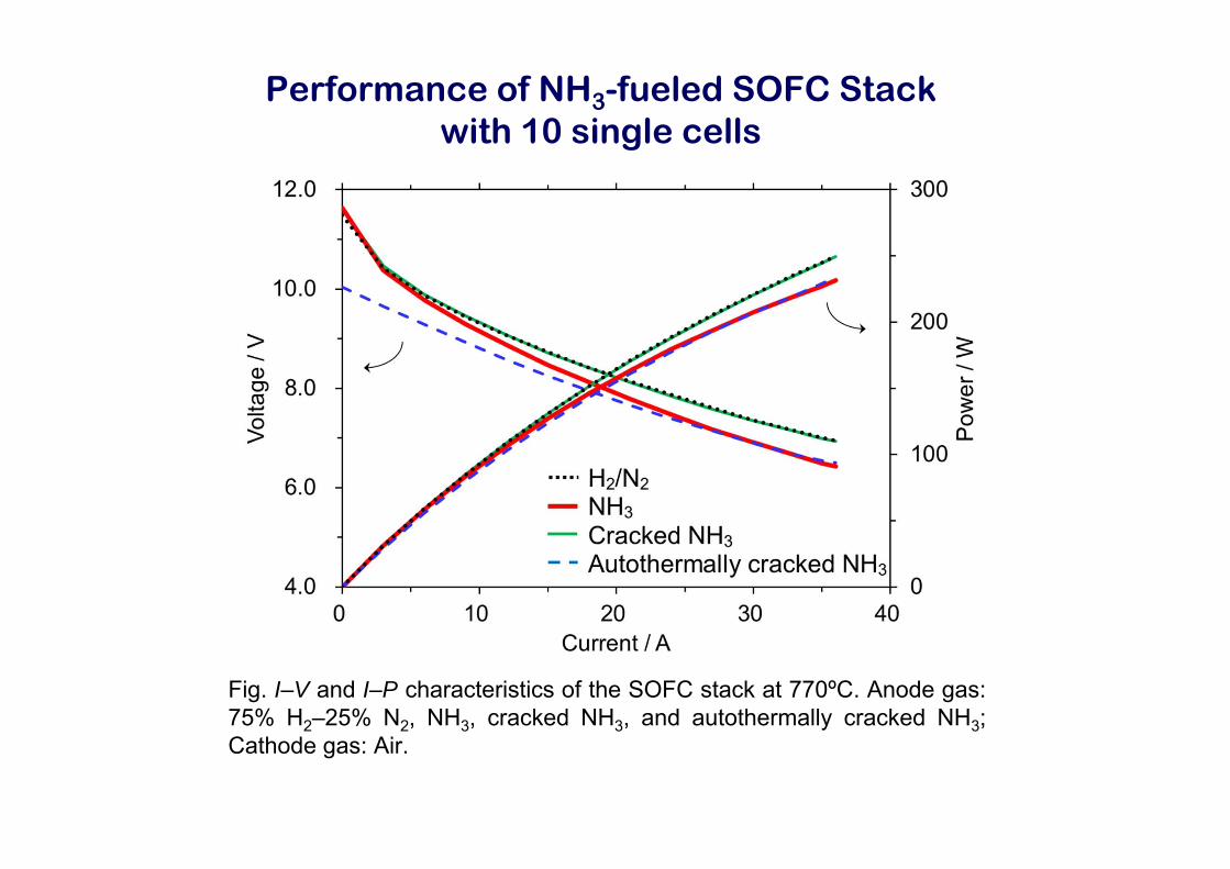
Fig. I–V and I–P characteristics of the SOFC stack at 770ºC. Anode gas:75% H2–25% N2, NH3, cracked NH3, and autothermally cracked NH3;Cathode gas: Air.
Performance of NH3-fueled SOFC Stack with 10 single cells

Summary
The rapid start-up less than 130 sec was possible with the autothermalNH3 cracker.
The SOFC stack with 30 single cells fueled with NH3 exhibited 1 kWpower at ca. 750ºC.
The DC generation efficiency of 1 kW class SOFC stack was 50% orhigher.
Acknowledgment
This work was supported by the Council for Science, Technology andInnovation (CSTI) Cross-ministerial Strategic Innovation Promotion Program(SIP) “energy carrier” (Funding agency: JST).