development of semi-continuous solar powered …
TRANSCRIPT

Journal of Thermal Engineering, Vol. 4, No. 4, Special Issue 8, pp. 2169-2187, June, 2018
Yildiz Technical University Press, Istanbul, Turkey
This paper was recommended for publication in revised form by Regional Editor Hafız Muhammed Ali 1BVM Engineering College, V.V Nagar 388120 India 2Shri Labhubhai Trivedi Institute of Engineering and Technology, Rajkot 360005 India 3RGM College of Engineering and Technology, Nandyal 518501 India 4 Gallogly College of Engineering, University of Oklahoma, Norman, OK 73019 *E-mail address: [email protected] Manuscript Received 27 August 2017, Accepted 17 December 2017
DEVELOPMENT OF SEMI-CONTINUOUS SOLAR POWERED ADSORPTION WATER CHILLER FOR FOOD PRESERVATION
Hitesh Bhargav1*, Bharat Ramani2, V. Siva Reddy3, Feng C. Lai4
ABSTRACT
Solar powered adsorption refrigeration systems have been preserved the food for the national requirement
and also protected the environment. In this research article, the design and development of semi-continuous solar
powered Adsorption water chiller for food preservation are presented. The design of the main components includes
an adsorber bed, a condenser, an expansion device and an evaporator are performed by using heat transfer
correlations. The outcomes of design are presented and discussed. The cooling produced in 10 kg of water was 554
kJ in 6 hours for the water flow of 170 kg/hour, 25° C condenser temperature and 65° C adsorber temperature.The
fluctuation in system pressure is observed in the range of 30 kPa to 80 kPa for desorption and adsorption process
during experimentation. The chiller performance was tested and compared with the earlier adsorption chiller. The
comparison showed that proposed chiller has higher specific cooling power (SCP), low cycle time and low
generation temperature due to activated carbon fiber-methanol pair and effective design of the system.
Keyword: Solar Energy, Adsorption Refrigeration, Food Preservation, ACF-Methanol
INTRODUCTION
Solar powered adsorption refrigeration system uses natural refrigerant and operates at low generation
temperature which can be achieved by a flat plate collector. This system uses very low intrinsic parts which can be
operated with no or little electricity. The main drawback of adsorption cooling is lower COP and higher thermal
mass. Many researchers have made efforts for improvement in performance and reduction in overall mass of the
system. Solar based cooling systems are intermittent due to nature of availability of solar energy. To develop a
continuous cooling system, energy storage or double bed must be designed which ultimately adds cost and extra
equipment. An adsorption chiller is thermally driven refrigeration system operated by solar energy or waste heat.
The construction is the same to vapour compression refrigeration system except for thermal compressor. Other
components like evaporator, condenser and expansion device are same. Due to the porous structure of adsorbent,
refrigerant from the evaporator is adsorbed at low temperature and pressure which produces a cooling effect.
Adsorbed mass of refrigerant is desorbed by supplying heat to adsorbent material and adsorbed by providing low
temperature to the adsorbent. In this way, the intermittent cycle is operated, and cooling is produced by heating &
cooling the adsorber bed periodically. Isobaric adsorption and desorption with temperature swing operation in
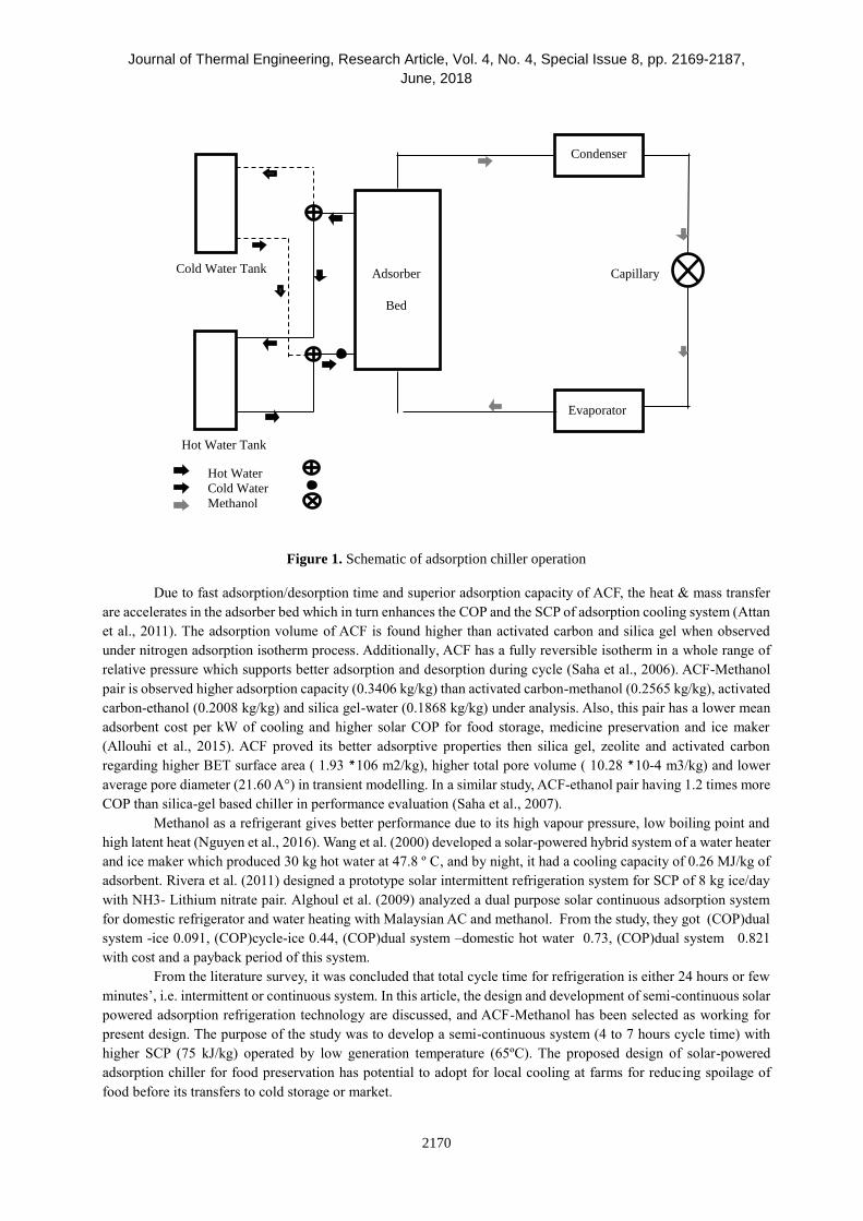
adsorber bed produce refrigerating effect. Figure 1 shows the schematic diagram of adsorption chiller operation.
Adsorption chiller works on physiosorption phenomenon in which adsorbate gathers over the surface of
the adsorbent. In this phenomenon, adsorption processes occur due to lower temperature of adsorber bed (20 – 35
°C) and desorption due to the higher temperature of adsorber bed (60 – 90 °C) which is attainable by solar energy.
The refrigeration is produced by repeated heating & cooling of adsorber bed by hot & cold water. The solar-powered
Adsorption chiller consists of ETC, water tank (hot/cold), adsorber bed, condenser, evaporator and capillary tube.
In daytime solar energy is collected by ETC and subsequently converted into hot water. By keeping separate hot and
cold water tanks, adsorber bed obtains heating and cooling for system process. Figure 2 represents the Clapeyron
diagram for the thermodynamic cycle.
For refrigeration applications, ACF has a potential as an adsorbent due to its high adsorption capacity.ACF
provides larger surface area and ease in packing which makes it favourable for adsorber bed (El-Sharkawy et al.,
2016). Moreover, ACF performs the best in a cyclic adsorption/desorption in which time cycle is 1/5 to 1/10 of
activated carbon (Wang et al., 1997).
Journal of Thermal Engineering, Research Article, Vol. 4, No. 4, Special Issue 8, pp. 2169-2187,
June, 2018
2170
Figure 1. Schematic of adsorption chiller operation
Due to fast adsorption/desorption time and superior adsorption capacity of ACF, the heat & mass transfer
are accelerates in the adsorber bed which in turn enhances the COP and the SCP of adsorption cooling system (Attan
et al., 2011). The adsorption volume of ACF is found higher than activated carbon and silica gel when observed
under nitrogen adsorption isotherm process. Additionally, ACF has a fully reversible isotherm in a whole range of
relative pressure which supports better adsorption and desorption during cycle (Saha et al., 2006). ACF-Methanol
pair is observed higher adsorption capacity (0.3406 kg/kg) than activated carbon-methanol (0.2565 kg/kg), activated
carbon-ethanol (0.2008 kg/kg) and silica gel-water (0.1868 kg/kg) under analysis. Also, this pair has a lower mean
adsorbent cost per kW of cooling and higher solar COP for food storage, medicine preservation and ice maker
(Allouhi et al., 2015). ACF proved its better adsorptive properties then silica gel, zeolite and activated carbon
regarding higher BET surface area ( 1.93 106 m2/kg), higher total pore volume ( 10.28 10-4 m3/kg) and lower
average pore diameter (21.60 A°) in transient modelling. In a similar study, ACF-ethanol pair having 1.2 times more
COP than silica-gel based chiller in performance evaluation (Saha et al., 2007).
Methanol as a refrigerant gives better performance due to its high vapour pressure, low boiling point and
high latent heat (Nguyen et al., 2016). Wang et al. (2000) developed a solar-powered hybrid system of a water heater
and ice maker which produced 30 kg hot water at 47.8 º C, and by night, it had a cooling capacity of 0.26 MJ/kg of
adsorbent. Rivera et al. (2011) designed a prototype solar intermittent refrigeration system for SCP of 8 kg ice/day
with NH3- Lithium nitrate pair. Alghoul et al. (2009) analyzed a dual purpose solar continuous adsorption system
for domestic refrigerator and water heating with Malaysian AC and methanol. From the study, they got (COP)dual
system -ice 0.091, (COP)cycle-ice 0.44, (COP)dual system –domestic hot water 0.73, (COP)dual system 0.821
with cost and a payback period of this system.
From the literature survey, it was concluded that total cycle time for refrigeration is either 24 hours or few
minutes’, i.e. intermittent or continuous system. In this article, the design and development of semi-continuous solar
powered adsorption refrigeration technology are discussed, and ACF-Methanol has been selected as working for
present design. The purpose of the study was to develop a semi-continuous system (4 to 7 hours cycle time) with
higher SCP (75 kJ/kg) operated by low generation temperature (65ºC). The proposed design of solar-powered
adsorption chiller for food preservation has potential to adopt for local cooling at farms for reducing spoilage of
food before its transfers to cold storage or market.
Hot Water
Cold Water
Methanol
Cold Water Tank
Hot Water Tank
Adsorber
Bed
Condenser
Evaporator
Capillary

Journal of Thermal Engineering, Research Article, Vol. 4, No. 4, Special Issue 8, pp. 2169-2187,
June, 2018
2171
Figure 2. Clapeyron diagram for the adsorption chiller thermodynamic cycle
DESIGN PROCESS
The design of adsorption refrigeration system relies on knowledge of chemical science, heat and
refrigeration technology. With the physiosorption principal and necessity of refrigerating effect, the design of the
system was performed. For food preservation, the temperature of storage system should be maintained at 10° C (i.e.
vegetables and fruits can be preserved at this temperature for one or two weeks) (Zhai et al., 2013). An Adsorption
chiller was designed for producing water temperature at 8-10 ° C in 4 to 6 hour. The cycle time for this whole process
was 360 minutes, and hence it works as a semi-continuous system. The size of the system is decided by the
adsorption capacity of adsorbent. For the adsorption capacity of the working pair, the experimental setup was
developed, and the value came out as 0.44 kg/kg.
The required mass of refrigerant is determined by the cooling effect and adsorption capacity. The gained
mass decides the size of the chiller. In India as well as other parts of the world, the solar water heater is based on
flat plate collector which can produce water temperature up to 55-70° C. Adsorption working pair is chosen in such
a way that it will give satisfactory results at such low generation temperature. This system can easily be coupled
with a solar water heater to give twin advantages of hot water and refrigerating effect (Sumathy et al., 2013).The
system is designed in a way that is effective, reasonable, compact and eases in manufacture with readily available
resources.
The design of adsorption chiller is based on the following assumption,
Specific heat & density are constant
Adsorbent bed is composed of uniform size
particles and the bed porosity is constant
Heat transfer in the heating /cooling fluids and the metal is one dimensional
No environmental effect and steady state during operation
Mass of Methanol and ACF
The mass of methanol is achieved by cooling requirement of product, i.e. water,
Qref = 𝑚𝑤𝑐𝑝𝑤𝑑𝑇 (1)
6
5
High
Concentration
Low
Concentration
4
3 2
1
lnP
-1/T
Pcon
Pevp
Tevp
Tatm
Tads
Adsorber
Chiller
1-2: Isosteric Heating 2-5: Condensation
2-3: Desorption 5-6: Expansion
3-4: Isosteric Cooling 6-1: Evaporation
4-1: Adsorption
Saturated
Refrigerant

Journal of Thermal Engineering, Research Article, Vol. 4, No. 4, Special Issue 8, pp. 2169-2187,
June, 2018
2172
𝑚𝑟𝑒𝑓 =
Qref
hfg
(2)
Either by using Dubinin Astakhov correlation or physical measurement, the value of adsorption capacity is
achieved.
𝑥 =𝑚𝑟𝑒𝑓
𝑚𝑎𝑑𝑠
(3)
From above equation, the mass of ACF is calculated.
Adsorber Bed Design
In this study, shell and tube heat exchanger is chosen for adsorber bed. From literature survey and heat
transfer analysis, the heat exchanger dimensions are identified. In this research, diameter and length of shell and
tube are given, and a number of the tubes is then calculated. Also, the mass flow rates, the temperatures of refrigerant
and heat transfer fluid are identified. Using TEMA code and heat transfer correlation, the final dimensions of the
heat exchanger are available in Table 1. The bed schematic and photograph is shown in Figure 3.
Table 1. Calculated dimensions for adsorber bed
Parameter Specification
Heat Exchanger Shell and tube type
Area 0.22 m2
Shell 154 mm in diameter,750 mm length
Tube 9.5 mm in diameter, cu.,26 nos.
Figure 3. Shell and tube type adsorber bed
Heat Duty in adsorber bed
Qads = 𝑚𝑚𝑐𝑝𝑚𝑑𝑇𝑚 (4)
Calculate hi (h clean) for tube side by using Nusselt correlation,
Reynolds number

Journal of Thermal Engineering, Research Article, Vol. 4, No. 4, Special Issue 8, pp. 2169-2187,
June, 2018
2173
𝑅𝑒 =
𝜌𝑢𝐷
µ
(5)
Apply for laminar flow
𝑁𝑢 = 0.332𝑅𝑒0.5Pr0.33 (6)
And
hi =
Nuk
D
(7)
hi = hclean (8)
Calculate hfoul by considering the effect of fouling factor,
𝑅𝑓 =1
hfoul−
1
hclean
The value of Rf is 0.001 for city water (Standards of the Tubular Exchanger Manufacturers Association,
2007).Using theory of adsorbent thickness (≤ Ycritical) for better flow of methanol and ease in penetration, three
layers of ACF is taken in the experiment (Mitra, 2016). For heat transfer from the tube fluid to shell refrigerant, four
thermal resistance are involved- inside, cu tube, ACF and outside (Holman, 2008)
𝑅𝑖 =
1
hfoulAi
(9)
𝑅𝑐𝑢 =ln (
Ro
Ri)
2𝜋kcuL
(10)
𝑅𝑎𝑐𝑓 =ln (
Rao
Rai)
2𝜋kacfL
(11)
The overall heat transfer coefficient can then be expressed regarding these four resistances,
Uo =
1
(Ri + Rcu + Racf + Ro)Ao
(12)
And the area of the heat exchanger is calculated to be
𝐴 =
Qads
Uo F LMTD
(13)
Where F is a correction factor, and its value is unity (Holman, 2008). From the area obtained, one can find
the number of tubes for the heat exchanger. The radius of ACF must be less than the critical radius for better heat
transfer and smaller pressure drop inside the shell. The pressure drop must be less than allowable pressure drop
(Holman, 2008 & Donald Q.Kern, 2009). Three layers of ACF is wrapped over the tubes, allowing the space between
Journal of Thermal Engineering, Research Article, Vol. 4, No. 4, Special Issue 8, pp. 2169-2187,
June, 2018
2174
tubes for methanol vapour to flow in the shell during desorption, hence the pressure drop in the shell is less compared
to the allowable drop.
Condenser Design
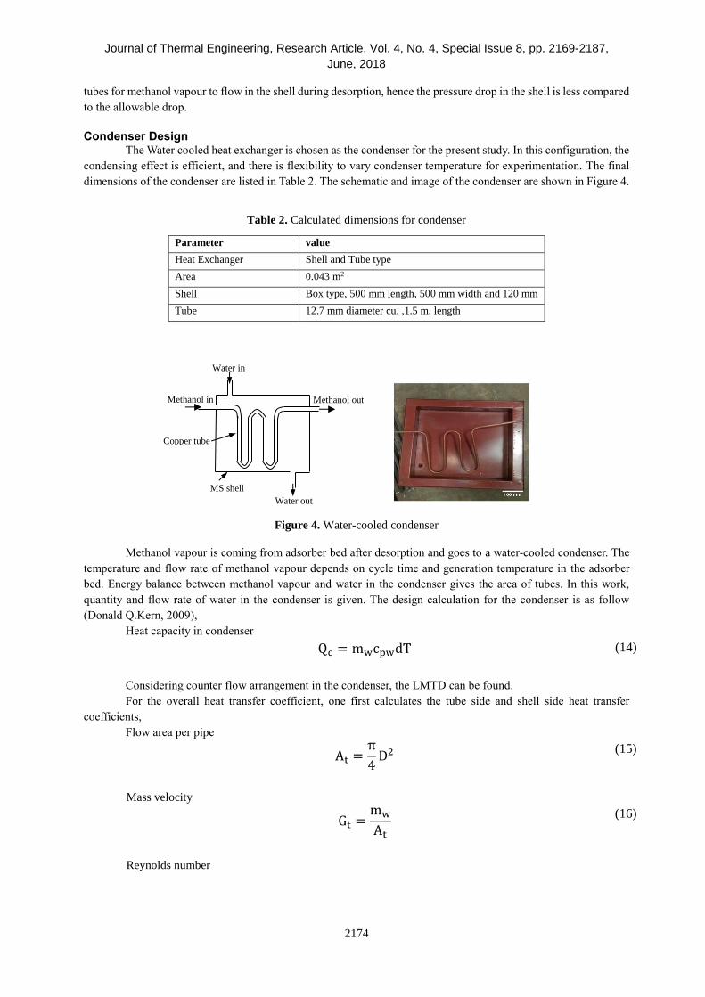
The Water cooled heat exchanger is chosen as the condenser for the present study. In this configuration, the
condensing effect is efficient, and there is flexibility to vary condenser temperature for experimentation. The final
dimensions of the condenser are listed in Table 2. The schematic and image of the condenser are shown in Figure 4.
Table 2. Calculated dimensions for condenser
Parameter value
Heat Exchanger Shell and Tube type
Area 0.043 m2
Shell Box type, 500 mm length, 500 mm width and 120 mm
height Tube 12.7 mm diameter cu. ,1.5 m. length
Figure 4. Water-cooled condenser
Methanol vapour is coming from adsorber bed after desorption and goes to a water-cooled condenser. The
temperature and flow rate of methanol vapour depends on cycle time and generation temperature in the adsorber
bed. Energy balance between methanol vapour and water in the condenser gives the area of tubes. In this work,
quantity and flow rate of water in the condenser is given. The design calculation for the condenser is as follow
(Donald Q.Kern, 2009),
Heat capacity in condenser
Qc = mwcpwdT (14)
Considering counter flow arrangement in the condenser, the LMTD can be found.
For the overall heat transfer coefficient, one first calculates the tube side and shell side heat transfer
coefficients,
Flow area per pipe
At =π
4D2
(15)
Mass velocity
Gt =mw
At
(16)
Reynolds number
Copper tube
MS shell
Water out
Water in
Methanol out Methanol in
Journal of Thermal Engineering, Research Article, Vol. 4, No. 4, Special Issue 8, pp. 2169-2187,
June, 2018
2175
Ret =
DGt
µ
(17)
Tube side heat transfer coefficient
hi = jh (
k
D) (cpµ/k)0.33 (µ/µw)0.14
(18)
Where jh = (hiD/k) (cpµ/k)0.33 (µ/µw
)0.14
Including the thickness of tube, the corrected heat transfer coefficient is given by
hio =
hidi
do
(19)
Shell side heat transfer coefficient
We first assume a shell side heat transfer coefficient (ho) and by trial and error, fix it using the tube wall
and condensate film temperatures.
The overall heat transfer coefficient (Uc) for a clean tube can be calculated by
Uc =
hiho
hi + ho
(20)
Consider the dust coefficient (hd),
hd =
1
Rd
(21)
The overall design Coefficient (Ud) is then given by
Ud =
Uchd
Uc + hd
(22)
Now the area required for the condenser tube (Ac) is given by,
Ac =
Qc
Ud LMTD
(23)
The calculated area gives the total tube length required for the condenser.
Expansion Device An adsorption refrigeration system with ACF-methanol as the working pair works under vacuum so that
the capillary tube is sufficient to maintain the pressure difference in the system. The dimensions are calculated for
the capillary tube are summarized in Table 3. In the capillary tube, the pressure drop is due to friction and flashing
effect. This pressure drop is directly proportional to the length of the tube and inversely proportional to its diameter.
In this chiller, total pressure drop observed in the capillary is 51 kPa, i.e. from condenser pressure 55 kPa to
evaporator pressure 4 kPa.
The design of capillary tube implies selection of bore and calculation of length for maintaining the required
flow at the given pressure difference between condenser and evaporator. Following is the design procedure for
capillary tube:
Journal of Thermal Engineering, Research Article, Vol. 4, No. 4, Special Issue 8, pp. 2169-2187,
June, 2018
2176
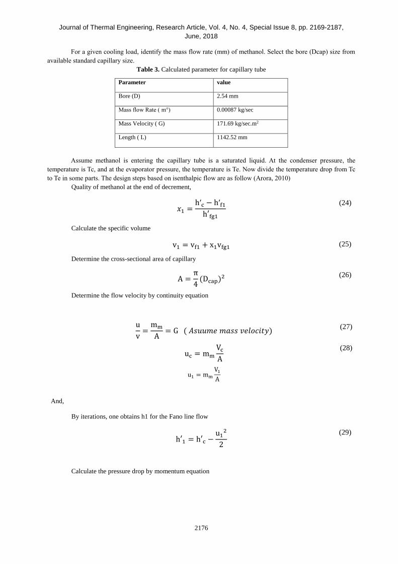
For a given cooling load, identify the mass flow rate (mm) of methanol. Select the bore (Dcap) size from
available standard capillary size.
Table 3. Calculated parameter for capillary tube
Parameter value
Bore (D) 2.54 mm
Mass flow Rate ( m°) 0.00087 kg/sec
Mass Velocity ( G) 171.69 kg/sec.m2
Length ( L) 1142.52 mm
Assume methanol is entering the capillary tube is a saturated liquid. At the condenser pressure, the
temperature is Tc, and at the evaporator pressure, the temperature is Te. Now divide the temperature drop from Tc
to Te in some parts. The design steps based on isenthalpic flow are as follow (Arora, 2010)
Quality of methanol at the end of decrement,
𝑥1 =
h′c − h′f1
h′fg1
(24)
Calculate the specific volume
v1 = vf1 + x1vfg1 (25)
Determine the cross-sectional area of capillary
A =π
4(Dcap)2
(26)
Determine the flow velocity by continuity equation
u
v=
mm
A= G ( 𝐴𝑠𝑢𝑢𝑚𝑒 𝑚𝑎𝑠𝑠 𝑣𝑒𝑙𝑜𝑐𝑖𝑡𝑦)
(27)
uc = mm
Vc
A
(28)
And,
u1 = mm
V1
A
By iterations, one obtains h1 for the Fano line flow
h′1 = h′c −
u12
2
(29)
Calculate the pressure drop by momentum equation
Journal of Thermal Engineering, Research Article, Vol. 4, No. 4, Special Issue 8, pp. 2169-2187,
June, 2018
2177
∆Pa =mm
A(uc − u1) = G (uc − u1)
(30)
Determine the pressure drop due to friction
∆pf = ∆p − ∆pa (31)
Now relate the pressure drop to friction factor,
∆pf = (ρfLu2)/(2D) (32)
Simplify the equation to give
∆pf = Yfu∆L (33)
Where Y= (G/2D) and f = (0.324/Re0.25)
In this way, ∆𝐿 is calculated and summation of ∆𝐿 will give the total length of the capillary tube.
Evaporator After reviewing literature for water chiller, it is found that immersion coil type heat exchanger is the best
configuration. The mass of methanol and quantity of product decide the size of the heat exchanger. Thermal and
mechanical design of coil type heat exchanger has performed accordingly. The final dimensions obtained are shown
in Table 4.
Table 4. Calculated parameters for evaporator
Parameter value
Heat Exchanger Shell and coil type
Area 0.24 m2
Shell 200 mm in diameter, 400 mm high
Tube 12.7 mm in diameter, 6 m. long
The schematic and photograph of the evaporator are shown in Figure 5. The helical coil heat exchanger is
best suited for laminar flow and limited space. The design of helical coil and shell is determined by the mass
velocities of the fluids. The following are the steps in the design of evaporator (Patil, 1982).Calculate the overall
heat transfer coefficient,
For laminar flows, the shell side heat transfer coefficient (ho) is given by,
(ho
De
k) = 0.6 (Re)0.5(Pr)0.31
(34)
And the tube side heat transfer coefficient (hi),
hi = jh (
k
D) (Npr)0.33
(35)

Journal of Thermal Engineering, Research Article, Vol. 4, No. 4, Special Issue 8, pp. 2169-2187,
June, 2018
2178
Now, the corrected tube side coefficient (hio) is given by,
hio =
hiD
Do
(36)
The overall heat transfer coefficient
1
U=
1
ho+
1
hio+
x
k+ Rc + Rs
(37)
Where x is the coil thickness, k is the thermal conductivity of coil metal, Rc & Rs are the fouling factors
for coil and shell respectively.
Now the area required for the helical coil is
Acoil =
Qref
U LMTD
(38)
Where Qref is the cooling load in the evaporator. The calculated area gives the total tube length required
for the evaporator.
The heat transfer fluid is water which is 250 litre in capacity. Two separate tanks are provided for hot and
cold water which is supplied in a cycle to the bed as shown in Figure 6. Water tanks and other equipment are enclosed
with insulation. The specifications of insulation are listed in Table 5. The final calculated dimensions with
specifications of adsorption chiller are summarized in Table 6.
Figure 5. Immersion coil type evaporator
Water out
Water Three
Way Valve Pump
Methanol to adsorber
Methanol from receiver

Journal of Thermal Engineering, Research Article, Vol. 4, No. 4, Special Issue 8, pp. 2169-2187,
June, 2018
2179
Figure 6. Hot and cold water tank
Table 5. Specifications of insulation
Insulation Cover Specification
Water Tank Rock Wool, density 48 kg/ m3 , 100 mm thick
Evaporator Puf, density 40 kg/ m3, 50 mm thick
Condenser Rock Wool, density 48 kg/ m3 , 50 mm thick
Table 6. Final specification of adsorption chiller
Component Type Specification
Adsorber bed Shell and tube Shell: 154 mm in diameter, 750 mm long
Tube: 3/8 inch cu. ,26 tubes
Evaporator Helical coil immersion
water cooled
Shell-12 L
Tube: ½ inch cu.6 m long,11 turns, 19.05 mm in pitch
Condenser Shell and tube
Water cooled
Box type shell- 25 L
Tube: ½ inch cu. , 1.5 m long
Hot/cold water tank Cylindrical insulated
tank
250 L capacity metal tank with insulation

Journal of Thermal Engineering, Research Article, Vol. 4, No. 4, Special Issue 8, pp. 2169-2187,
June, 2018
2180
EQUIPMENT DESCRIPTION
The schematic and photograph of semi-continuous solar powered adsorption chiller are shown in Figure 7
and Figure 8. This system comprises a hot water tank with temperature regulator to pretend solar water heater. With
this arrangement, experimentation can be conveniently conducted at any time and any location for simulated
conditions. For precise control, there was a thermostat with temperature relay attached to a water tank. With this
arrangement, manual control in the mass flow rate of water and temperature control of hot water and cold water was
possible.
Also, the frequency of water supply (hot water timing / cold water timing) is maintained. For measuring
the temperature at different locations of the system, calibrated K type thermocouples were installed. Dial pressure
gauge was used to provide system pressure during operation. The uncertainty analysis of instruments and set up are
listed in Table 7. There was also temperature controller provided in the condenser to monitor the real conditions.
The reduction in temperature of water kept in the evaporator shell gave cooling effect produced in each cycle. The
overall system design has been developed for better cooling effect, and the best combination of parameters for
efficient performance has been identified. To measure the drop in evaporator temperature, cyclic heating & cooling
of adsorber bed were required for a specific time. Heating was observed in adsorber bed by hot water and cooling
by tap water. For achieving the chilling effect in water, the temperature of hot & cold water, the frequency of water
supply and mass flow rate of the same were fixed. The hot water is flowing through adsorber bed for 10 min, measure
the temperature at adsorber bed as well as the evaporator and the system pressure. The same mentioned method is
followed by supplying cold water for 30 min to the bed.
Table 7. Uncertainty analysis-list of instruments with accuracy, range and percentage of errors
Instrument Accuracy Range % Error
K Type Thermocouple ± 0.1° C 0-400 °C 0.5
Dial Pressure Gauge ± 2 cm of hg 0-76 cm 1
Level Indicator ±0.5 mL 0-50 ml 0.5
Weighing Balance ±0.01 gm 0-500 gm 0.01
Hour Meter ±0.01 hour 0-9999.99 hour 0.01
Measuring Beaker ±0.5 mL 0-1000 ml 0.5
The total uncertainty found for adsorption capacity is 0.25%, Cooling Effect is 0.01 %, COP is 8% and
SCP is 1.71 %.
EXPERIMENTAL RESULTS The chiller is designed to achieve temperature drop of 10 ° C in the evaporator which can be beneficial for
food preservation. The temperature drop in the evaporator is 9° C achieved by water flow rate of 170 kg/hour and
at a condenser temperature 25°C. The variation in system pressure is observed from 230 mm of Hg. (30 kPa) to 600
mm of Hg. (80 kPa) for desorption and adsorption process during experimentation. The total time taken for a cooling
effect of 554 kJ is 6 hours which can be reduced by maintaining the flow rate of water. The maximum COP of the
system can be observed by electronics controls and time of water supply. The observed results are mentioned in
Table 8 in which evaporator temperature is decreasing in each cycle. In the results, 9° C drop in evaporator attained
in 6 hours. The variation in evaporator temperature and system pressure is shown in Figure 9 and Figure 10. The
drop in temperature of evaporator reflects the refrigerating effect produced by semi-continuous adsorption water
chiller. The fluctuation in system pressure is due to desorption and adsorption mechanism observed by heat transfer
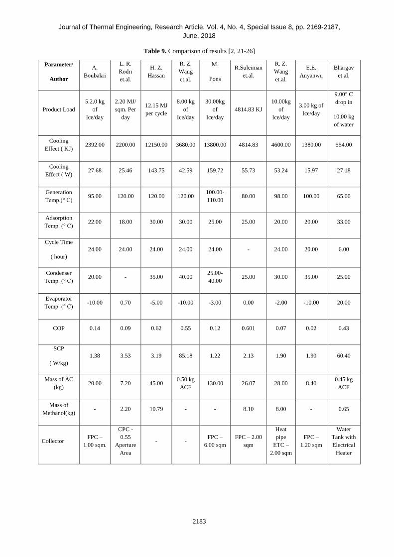
fluid (hot water/tap water) during the process. The test results are compared with previous studies as shown in Table
9. The comparison revealed that proposed adsorption system has lesser cycle time, the low mass of adsorbent and
refrigerant for higher SCP and COP. Even generation temperature is less which can help in selecting the low power
heat source and conventional solar collector for this chiller. The proposed system is produced desire cooling effect
by keeping moderate adsorption temperature (i.e. by using atmospheric air or tap water) and moderate desorption
temperature( Solar Water Heater). The presented adsorption chiller is better by selection of working pair, design and
optimization of working parameters.

Journal of Thermal Engineering, Research Article, Vol. 4, No. 4, Special Issue 8, pp. 2169-2187,
June, 2018
2181
Figure 7. Schematic of Adsorption water chiller

Journal of Thermal Engineering, Research Article, Vol. 4, No. 4, Special Issue 8, pp. 2169-2187,
June, 2018
2182
Table 8. Testing results
TIME
PRESSURE
(mm of Hg
vacuum)
Water Flow Rate
(kg/hour)
Avg. Hot Water
Temp(Degree C)
Avg. tap Water
Temp(Degree C)
Drop in
Evaporator water
Temp. (Degree C)
06.30pm 490.00 49.45 29.55 28.20
06.40 370.00 177.00 49.30 30.95 28.30
06.55 475.00 150.00 53.75 32.05 27.90
07.10 475.00 57.90 33.80 27.30
07.20 300.00 144.00 57.95 34.05 26.90
07.35 475.00 142.00 61.95 34.35 26.50
07.50 475.00 64.40 34.45 25.70
08.00 210.00 206.00 63.20 34.55 25.60
08.15 475.00 220.00 64.40 34.55 25.00
08.30 475.00 64.25 34.00 24.50
08.40 225.00 202.00 61.30 34.40 24.60
08.55 475.00 170.00 61.25 34.30 24.10
09.10 475.00 61.20 34.35 23.80
09.20 280.00 150.00 59.05 34.30 23.60
09.35 475.00 170.00 60.20 34.25 23.50
09.50 475.00 60.10 34.40 23.00
10.00 265.00 165.00 59.65 34.55 22.60
10.15 475.00 215.00 60.10 34.45 22.40
10.30 475.00 60.05 34.55 21.70
10.40 300.00 205.00 59.20 34.60 21.70
10.55 475.00 222.00 60.35 34.60 21.20
11.10 475.00 60.25 34.55 20.80
11.20 275.00 160.00 60.20 34.60 20.70
11.35 475.00 221.00 60.40 34.55 20.10
11.5 475.00 60.30 34.50 20.00
00.00 290.00 171.00 59.65 34.60 20.00
00.15 am 475.00 221.00 60.50 34.60 19.80
00.30 475.00 60.50 33.80 19.20
Journal of Thermal Engineering, Research Article, Vol. 4, No. 4, Special Issue 8, pp. 2169-2187,
June, 2018
2183
Table 9. Comparison of results [2, 21-26]
Parameter/
Author
A.
Boubakri
L. R.
Rodrı
et.al.
H. Z.
Hassan
R. Z.
Wang
et.al.
M.
Pons
R.Suleiman
et.al.
R. Z.
Wang
et.al.
E.E.
Anyanwu
Bhargav
et.al.
Product Load
5.2.0 kg
of
Ice/day
2.20 MJ/
sqm. Per
day
12.15 MJ
per cycle
8.00 kg
of
Ice/day
30.00kg
of
Ice/day
4814.83 KJ
10.00kg
of
Ice/day
3.00 kg of
Ice/day
9.00° C
drop in
10.00 kg
of water
Cooling
Effect ( KJ) 2392.00 2200.00 12150.00 3680.00 13800.00 4814.83 4600.00 1380.00 554.00
Cooling
Effect ( W) 27.68 25.46 143.75 42.59 159.72 55.73 53.24 15.97 27.18
Generation
Temp.(° C) 95.00 120.00 120.00 120.00
100.00-
110.00 80.00 98.00 100.00 65.00
Adsorption
Temp. (° C) 22.00 18.00 30.00 30.00 25.00 25.00 20.00 20.00 33.00
Cycle Time
( hour)
24.00 24.00 24.00 24.00 24.00 - 24.00 20.00 6.00
Condenser
Temp. (° C) 20.00 - 35.00 40.00
25.00-
40.00 25.00 30.00 35.00 25.00
Evaporator
Temp. (° C) -10.00 0.70 -5.00 -10.00 -3.00 0.00 -2.00 -10.00 20.00
COP 0.14 0.09 0.62 0.55 0.12 0.601 0.07 0.02 0.43
SCP
( W/kg)
1.38 3.53 3.19 85.18 1.22 2.13 1.90 1.90 60.40
Mass of AC
(kg) 20.00 7.20 45.00
0.50 kg
ACF 130.00 26.07 28.00 8.40
0.45 kg
ACF
Mass of
Methanol(kg) - 2.20 10.79 - - 8.10 8.00 - 0.65
Collector FPC –
1.00 sqm.
CPC -
0.55
Aperture
Area
- - FPC –
6.00 sqm
FPC – 2.00
sqm
Heat
pipe
ETC –
2.00 sqm
FPC –
1.20 sqm
Water
Tank with
Electrical
Heater

Journal of Thermal Engineering, Research Article, Vol. 4, No. 4, Special Issue 8, pp. 2169-2187,
June, 2018
2184
Figure 8. Photograph of Adsorption Chiller
Figure 9. Variation in Evaporator temperature with
time
Figure 10. Variation in system pressure with time
18
20
22
24
26
28
30
18.00 20.00 22.00 24.00
Evap
ora
tor
Tem
per
atu
re i
n D
egre
e C
Time in hour
200
250
300
350
400
450
500
550
600
18.00 20.00 22.00 24.00
Syst
em P
ress
ure
in
mm
of
hg(v
acu
um
)
Time in hours
Temperature
Scanner Evaporator
Adsorption Bed
Condenser
Pressure Gauge
Hot Water Tank
Cold Water Tank

Journal of Thermal Engineering, Research Article, Vol. 4, No. 4, Special Issue 8, pp. 2169-2187,
June, 2018
2185
CONCLUSION
The solar-powered adsorption refrigeration system is undoubtedly a better option than a conventional
chiller because of its eco-friendly nature, low cost and simplicity. The objective of the study is to develop semi-
continuous adsorption water chiller powered by the residential solar water heater. From the obtained results it is
concluded that hybridizing of the solar water heater with adsorption refrigerator can satisfy water heating and food
preservation requirement. The working environment in term of the temperature of hot water & cold water, the flow
rate of water and temperature of the condenser can easily manage with available resources for the production of
cooling effect through the developed chiller. This chiller is expected to be reasonable in INDIA in upcoming time
for short-term storage of food at the farm. The present system can achieve high SCP at low generation temperature
by adsorptive properties of working pair and efficient design of chiller. The off-site observation and control can be
possible by proper electronic instrument and software with the system.
NOMENCLATURE
A Heat transfer area (m2)
ACF Activated carbon fiber
BET Brunauer–Emmett–Teller
Cp Specific heat (kJ kg-1 K-1)
COP Coefficient of performance
Cu Copper
D Inside diameter of tube (m)
Dcap Capillary bore
De Shell side equivalent diameter
Do Outside diameter of tube
dT Temperature drop in water
dTm Temperature difference in methanol
ETC Evacuated tube collector
G Mass velocity
h Convective heat transfer coefficient
h’ Enthalpy
i Inside
k Thermal conductivity (W m-1 K-1)
L Length of pipe (m)
LMTD Log mean temperature difference
mref Mass of Methanol (kg)
mw Mass flow rate of water (kg s-1)
hfg Latent heat of methanol
mads Mass of ACF(kg)
mm Mass flow rate of methanol(kg s-1)
Nu Nusselt number
o Outside
Q Heat flux (kW)
Pr Prandtl number
R Resistance to heat transfer
Re Reynolds number

Journal of Thermal Engineering, Research Article, Vol. 4, No. 4, Special Issue 8, pp. 2169-2187,
June, 2018
2186
SCP Specific cooling power ( kJ/kg)
T Temperature (K)
TEMA Tubular exchanger manufacturers association
u Free stream velocity of the fluid (m s-1)
v Specific volume
x Adsorption capacity (kg of methanol / kg of ACF)
ρ Density (kg m-3)
∆P Pressure drop
∆L Incremental length of capillary tube
µ Dynamic Viscosity
REFERENCES [1] El-Sharkawy I.I., Kuwahara K, Saha B.B., Koyama S., Ng K.C. (2006). Experimental investigation of activated
carbon fibers/ethanol pairs for adsorption cooling system application. Applied Thermal Engineering, 26: 859–865
[2] Wang R.Z., Jia J.P., Zhu Y.H., Teng Y., Wu J.Y., Cheng J., Wang Q.B. (1997). Study on a new solid absorption
refrigeration pair: active carbon fiber-methanol. Journal of Solar Energy Engineering, 119: 214–218
[3] Attan, D., Alghoul, M. A., Saha, B. B., Assadeq, J., & Sopian, K. (2011). The role of activated carbon fiber in
adsorption cooling cycles. Renewable and Sustainable Energy Reviews, 15(3), 1708-1721.
[4] Saha, B. B., Koyama, S., El-Sharkawy, I. I., Kuwahara, K., Kariya, K., Ng, K. C. (2006). Experiments for
measuring adsorption characteristics of an activated carbon fiber/ethanol pair using a plate-fin heat exchanger.
Hvac&R Research, 12(S2), 767-782.
[5] Saha, B. B., El-Sharkawy, I. I., Chakraborty, A., Koyama, S., Yoon, S. H., Ng, K. C. (2006). Adsorption rate of
ethanol on activated carbon fiber. Journal of Chemical & Engineering Data, 51(5), 1587-1592.
[6] Allouhi, A., Kousksou, T., Jamil, A., El Rhafiki, T., Mourad, Y., & Zeraouli, Y. (2015). Optimal working pairs
for solar adsorption cooling applications. Energy, 79, 235-247.
[7] Saha, B. B., El-Sharkawy, I. I., Chakraborty, A., Koyama, S. (2007). Study on an activated carbon fiber–ethanol
adsorption chiller: Part I–system description and modelling. International Journal of Refrigeration, 30(1), 86-95.
[8] Saha, B. B., El-Sharkawy, I. I., Chakraborty, A., & Koyama, S. (2007). Study on an activated carbon fiber–
ethanol adsorption chiller: Part II–performance evaluation. International journal of refrigeration, 30(1), 96-102.
[9]Nguyen BT, Nguyen HL, Nguyen TC, Cordova KE, Furukawa H (2016). High Methanol Uptake Capacity in
Two New Series of Metal-Organic Frameworks: Promising Materials for Adsorption-Driven Heat Pump
Applications. Chemistry of Materials, 28: 6243–6249
[10] Wang RZ, Li M,. Xu YX, Wu JY(2000). An energy efficient hybrid system of solar powered water heater and
adsorption ice maker. Solar Energy, 68: 189–195
[11] Rivera W, Moreno-Quintanar G, Rivera CO, Best R and Mart F (2011). Evaluation of a solar intermittent
refrigeration system for ice production operating with ammonia/lithium nitrate. Solar Energy, 85: 38-45
[12] Alghoul MA, Sulaiman MY, Sopian K, Azmi BZ (2009). Performance of a dual-purpose solar continuous
adsorption system. Renewable Energy, 34: 920-927
[13] Zhai XQ, Wang XL, Wang T, Wang RZ (2013). A review on phase change cold storage in air-conditioning
system: Materials and applications. Renewable and Sustainable. Energy Reviews, 22: 108-120
[14] Sumathy K, Yeung KH, Yong L (2003). Technology development in the solar adsorption refrigeration systems,
Progress in Energy and Combustion Science, 29: 301-327
[15] Tubular Exchanger Manufacturers Association (2007), “Standards of the Tubular Exchanger Manufacturers
Association,” 9th ed., New York
[16] Holman, J. P. (2008). Heat Transfer,ninth edition, Tata McGraw-Hill, New Delhi
[17] Mitra S, Aswin, N, Dutta, P (2016). Scaling analysis and numerical studies on water vapour adsorption in a
columnar porous silica gel bed. International Journal of Heat and Mass Transfer, 95: 853–864
[18] Donald Q.Kern. (2009). Process Heat Transfer, nineteenth edition, Tata McGraw-Hill, New Delhi
[19] Arora CP. (2010). Refrigeration and Air Conditioning,fifth edition, Tata McGraw-Hill, New Delhi
[20] Patil RK, Shende BW, Ghosh PK (1982). Designing a Helical-Coil Heat Exchanger. Chemical Engineering,
New York
[21] Boubakri, A. (2006). Performance of an adsorptive solar ice maker operating with a single double function heat
exchanger (evaporator/condenser). Renewable energy, 31(11), 1799-1812.
[22] González, M. I., Rodríguez, L. R., & Lucio, J. H. (2009). Evaluation of thermal parameters and simulation of
a solar-powered, solid-sorption chiller with a CPC collector. Renewable energy, 34(3), 570-577.

Journal of Thermal Engineering, Research Article, Vol. 4, No. 4, Special Issue 8, pp. 2169-2187,
June, 2018
2187
[23] P. Thumautok, W. Wongsuwan, T. Kiatsiriroat, and C. Mai, “Performance analysis of a solar adsorption heating
and cooling system,” 4th C. Annu. Conf. Heat Mass Transf. 30-March-2006, pp. 8–10, 2006.
[24] Zhang, X. J., & Wang, R. Z. (2002). Design and performance simulation of a new solar continuous solid
adsorption refrigeration and heating hybrid system. Renewable Energy, 27(3), 401-415.
[25] Hassan, H. Z. (2013). Energy analysis and performance evaluation of the adsorption refrigeration system. ISRN
Mechanical Engineering, 2013.
[26] Pons, M., & Guilleminot, J. J. (1986). Design of an experimental solar-powered, solid-adsorption ice
maker. Journal of solar energy engineering, 108(4), 332-337.