development of superconducting technologies for the … · development of superconducting...
TRANSCRIPT
FurukawaReview,No.43 2013 10
1. INTRODUCTION
Superconductivity is that phenomenon where some met-als or compounds have no resistivity when it is cooled to extremely-low temperature. The phenomenon was dis-covered by Heike Kamerlingh Onnes who was a physicist of Leiden University one hundred-two year ago. He found that electrical resistance of mercury became zero at tem-perature of 4.2 K that was achieved by liquefaction of heli-um. In the year 1911, when the great physical phenome-non was discovered, the Xinhai [Hsin-hai] Revolution was happening and the Qing dynasty, which controlled China, was imploding in the next year. In Japan, Meiji emperor passed away and Taisyo era started in the following year. From then, the world was heading to a world war. On the other hand, around that time is the predawn of dramatic developments in science field, such as the introduction of Einstein’s theory of relativity and the quantum theory.
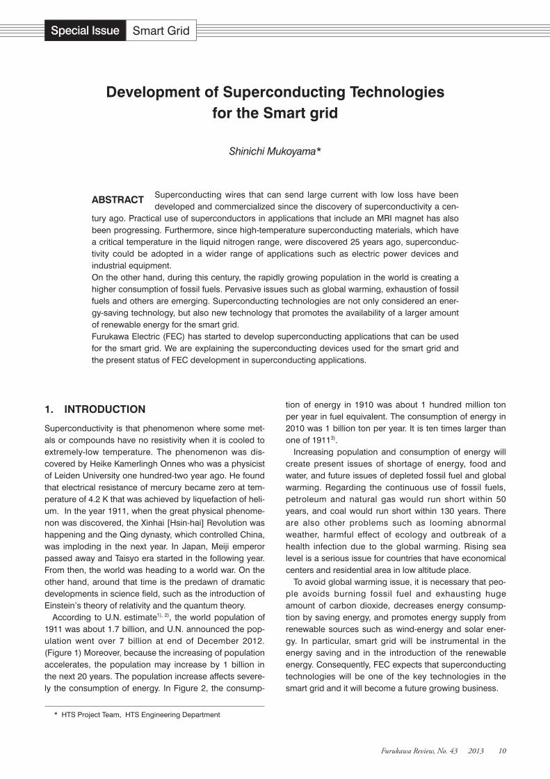
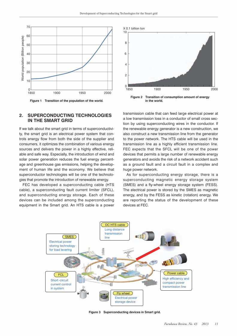
According to U.N. estimate1), 2), the world population of 1911 was about 1.7 billion, and U.N. announced the pop-ulation went over 7 billion at end of December 2012. (Figure 1) Moreover, because the increasing of population accelerates, the population may increase by 1 billion in the next 20 years. The population increase affects severe-ly the consumption of energy. In Figure 2, the consump-
tion of energy in 1910 was about 1 hundred million ton per year in fuel equivalent. The consumption of energy in 2010 was 1 billion ton per year. It is ten times larger than one of 19113).
Increasing population and consumption of energy will create present issues of shortage of energy, food and water, and future issues of depleted fossil fuel and global warming. Regarding the continuous use of fossil fuels, petroleum and natural gas would run short within 50 years, and coal would run short within 130 years. There are also other problems such as looming abnormal weather, harmful effect of ecology and outbreak of a health infection due to the global warming. Rising sea level is a serious issue for countries that have economical centers and residential area in low altitude place.
To avoid global warming issue, it is necessary that peo-ple avoids burning fossil fuel and exhausting huge amount of carbon dioxide, decreases energy consump-tion by saving energy, and promotes energy supply from renewable sources such as wind-energy and solar ener-gy. In particular, smart grid will be instrumental in the energy saving and in the introduction of the renewable energy. Consequently, FEC expects that superconducting technologies will be one of the key technologies in the smart grid and it will become a future growing business.
DevelopmentofSuperconductingTechnologiesfortheSmartgrid
Shinichi Mukoyama*
Superconducting wires that can send large current with low loss have been developed and commercialized since the discovery of superconductivity a cen-
tury ago. Practical use of superconductors in applications that include an MRI magnet has also been progressing. Furthermore, since high-temperature superconducting materials, which have a critical temperature in the liquid nitrogen range, were discovered 25 years ago, superconduc-tivity could be adopted in a wider range of applications such as electric power devices and industrial equipment.On the other hand, during this century, the rapidly growing population in the world is creating a higher consumption of fossil fuels. Pervasive issues such as global warming, exhaustion of fossil fuels and others are emerging. Superconducting technologies are not only considered an ener-gy-saving technology, but also new technology that promotes the availability of a larger amount of renewable energy for the smart grid.Furukawa Electric (FEC) has started to develop superconducting applications that can be used for the smart grid. We are explaining the superconducting devices used for the smart grid and the present status of FEC development in superconducting applications.
ABSTRACT
* HTS Project Team, HTS Engineering Department
Special Issue Smart Grid
Development of Superconducting Technologies for the Smart grid
FurukawaReview,No.43 2013 11
2. SUPERCONDUCTINGTECHNOLOGIESINTHESMARTGRID
If we talk about the smart grid in terms of superconductivi-ty, the smart grid is an electrical power system that con-trols energy flow from both the side of the supplier and consumers, it optimizes the combination of various energy sources and delivers the power in a highly effective, reli-able and safe way. Especially, the introduction of wind and solar power generation reduces the fuel energy percent-age and greenhouse gas emissions, helping the develop-ment of human life and the economy. We believe that superconductor technologies will be one of the technolo-gies that promote the introduction of renewable energy.
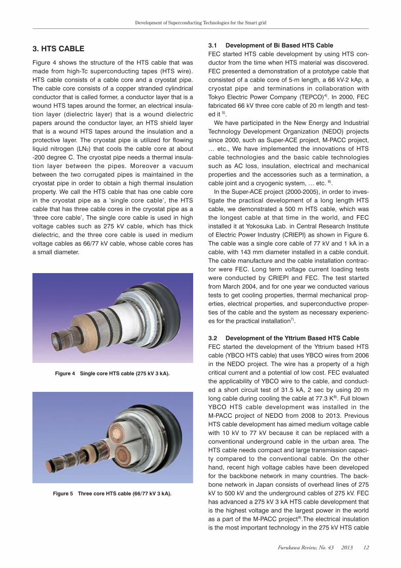
FEC has developed a superconducting cable (HTS cable), a superconducting fault current limiter (SFCL), and superconducting energy storage. Each of these devices can be included among the superconducting equipment in the Smart grid. An HTS cable is a power
transmission cable that can feed large electrical power at a low transmission loss in a conductor of small cross sec-tion by using superconducting wires in the conductor. If the renewable energy generator is a new construction, we also construct a new transmission line from the generator to the power network. The HTS cable will be used in the transmission line as a highly efficient transmission line. FEC expects that the SFCL will be one of the power devices that permits a large number of renewable energy generators and avoids the risk of a network accident such as a ground fault and a circuit fault in a complex and huge power network.
As for superconducting energy storage, there is a superconducting magnetic energy storage system (SMES) and a fly-wheel energy storage system (FESS). The electrical power is stored by the SMES as magnetic energy, and by the FESS as kinetic (rotation) energy. We are reporting the status of the development of these devices at FEC.
Figure1 Transitionofthepopulationoftheworld.
0
10
20
30
40
50
60
70
1850 1900 1950 2000
Wor
ld p
opul
atio
n (B
illio
n p
eop
le)
Figure2 Transitionofconsumptionamountofenergyintheworld.
1850
10
8
6
4
2
01900
X 0.1 billion ton
1950 2000
Figure3 SuperconductingdevicesinSmartgrid.
Fly wheel
FCL
Short -circuit current control in system
Electrical power storage device
Power cable
High efficiency and compact power transmission line
SMES
Electrical power storing technology for load levering
DC HTS cable
Long distance transmission line
Development of Superconducting Technologies for the Smart grid
FurukawaReview,No.43 2013 12
3.HTSCABLE
Figure 4 shows the structure of the HTS cable that was made from high-Tc superconducting tapes (HTS wire). HTS cable consists of a cable core and a cryostat pipe. The cable core consists of a copper stranded cylindrical conductor that is called former, a conductor layer that is a wound HTS tapes around the former, an electrical insula-tion layer (dielectric layer) that is a wound dielectric papers around the conductor layer, an HTS shield layer that is a wound HTS tapes around the insulation and a protective layer. The cryostat pipe is utilized for flowing liquid nitrogen (LN2) that cools the cable core at about -200 degree C. The cryostat pipe needs a thermal insula-tion layer between the pipes. Moreover a vacuum between the two corrugated pipes is maintained in the cryostat pipe in order to obtain a high thermal insulation property. We call the HTS cable that has one cable core in the cryostat pipe as a ‘single core cable’, the HTS cable that has three cable cores in the cryostat pipe as a ‘three core cable’, The single core cable is used in high voltage cables such as 275 kV cable, which has thick dielectric, and the three core cable is used in medium voltage cables as 66/77 kV cable, whose cable cores has a small diameter.
3.1 DevelopmentofBiBasedHTSCableFEC started HTS cable development by using HTS con-ductor from the time when HTS material was discovered. FEC presented a demonstration of a prototype cable that consisted of a cable core of 5-m length, a 66 kV-2 kAp, a cryostat pipe and terminations in collaboration with Tokyo Electric Power Company (TEPCO)4). In 2000, FEC fabricated 66 kV three core cable of 20 m length and test-ed it 5).
We have participated in the New Energy and Industrial Technology Development Organization (NEDO) projects since 2000, such as Super-ACE project, M-PACC project, … etc., We have implemented the innovations of HTS cable technologies and the basic cable technologies such as AC loss, insulation, electrical and mechanical properties and the accessories such as a termination, a cable joint and a cryogenic system, … etc. 6).
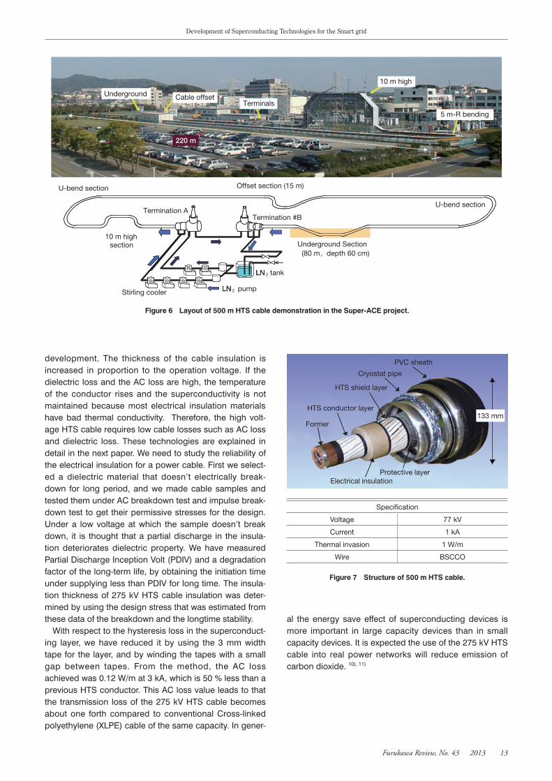
In the Super-ACE project (2000-2005), in order to inves-tigate the practical development of a long length HTS cable, we demonstrated a 500 m HTS cable, which was the longest cable at that time in the world, and FEC installed it at Yokosuka Lab. in Central Research Institute of Electric Power Industry (CRIEPI) as shown in Figure 6. The cable was a single core cable of 77 kV and 1 kA in a cable, with 143 mm diameter installed in a cable conduit. The cable manufacture and the cable installation contrac-tor were FEC. Long term voltage current loading tests were conducted by CRIEPI and FEC. The test started from March 2004, and for one year we conducted various tests to get cooling properties, thermal mechanical prop-erties, electrical properties, and superconductive proper-ties of the cable and the system as necessary experienc-es for the practical installation7).
3.2 DevelopmentoftheYttriumBasedHTSCableFEC started the development of the Yttrium based HTS cable (YBCO HTS cable) that uses YBCO wires from 2006 in the NEDO project. The wire has a property of a high critical current and a potential of low cost. FEC evaluated the applicability of YBCO wire to the cable, and conduct-ed a short circuit test of 31.5 kA, 2 sec by using 20 m long cable during cooling the cable at 77.3 K8). Full blown YBCO HTS cable development was installed in the M-PACC project of NEDO from 2008 to 2013. Previous HTS cable development has aimed medium voltage cable with 10 kV to 77 kV because it can be replaced with a conventional underground cable in the urban area. The HTS cable needs compact and large transmission capaci-ty compared to the conventional cable. On the other hand, recent high voltage cables have been developed for the backbone network in many countries. The back-bone network in Japan consists of overhead lines of 275 kV to 500 kV and the underground cables of 275 kV. FEC has advanced a 275 kV 3 kA HTS cable development that is the highest voltage and the largest power in the world as a part of the M-PACC project9).The electrical insulation is the most important technology in the 275 kV HTS cable
Figure4 SinglecoreHTScable(275kV3kA).
Figure5 ThreecoreHTScable(66/77kV3kA).
Development of Superconducting Technologies for the Smart grid
FurukawaReview,No.43 2013 13
development. The thickness of the cable insulation is increased in proportion to the operation voltage. If the dielectric loss and the AC loss are high, the temperature of the conductor rises and the superconductivity is not maintained because most electrical insulation materials have bad thermal conductivity. Therefore, the high volt-age HTS cable requires low cable losses such as AC loss and dielectric loss. These technologies are explained in detail in the next paper. We need to study the reliability of the electrical insulation for a power cable. First we select-ed a dielectric material that doesn’t electrically break-down for long period, and we made cable samples and tested them under AC breakdown test and impulse break-down test to get their permissive stresses for the design. Under a low voltage at which the sample doesn’t break down, it is thought that a partial discharge in the insula-tion deteriorates dielectric property. We have measured Partial Discharge Inception Volt (PDIV) and a degradation factor of the long-term life, by obtaining the initiation time under supplying less than PDIV for long time. The insula-tion thickness of 275 kV HTS cable insulation was deter-mined by using the design stress that was estimated from these data of the breakdown and the longtime stability.
With respect to the hysteresis loss in the superconduct-ing layer, we have reduced it by using the 3 mm width tape for the layer, and by winding the tapes with a small gap between tapes. From the method, the AC loss achieved was 0.12 W/m at 3 kA, which is 50 % less than a previous HTS conductor. This AC loss value leads to that the transmission loss of the 275 kV HTS cable becomes about one forth compared to conventional Cross-linked polyethylene (XLPE) cable of the same capacity. In gener-
al the energy save effect of superconducting devices is more important in large capacity devices than in small capacity devices. It is expected the use of the 275 kV HTS cable into real power networks will reduce emission of carbon dioxide. 10), 11)
Figure7 Structureof500mHTScable.
133 mm
PVC sheath
Cryostat pipe
HTS shield layer
HTS conductor layer
Former
Electrical insulationProtective layer
Specification
Voltage 77 kV
Current 1 kA
Thermal invasion 1 W/m
Wire BSCCO
Figure6 Layoutof500mHTScabledemonstrationintheSuper-ACEproject.
Termination A
Terminals
220 m
Cable offsetUnderground
Stirling cooler LN 2 pump
LN 2 tank
Underground Section(80 m,depth 60 cm)
Offset section (15 m)
section
Termination #B
LN
LN
10 m high
10 m high
5 m-R bending
U-bend section
U-bend section
Development of Superconducting Technologies for the Smart grid
FurukawaReview,No.43 2013 14
4. FAULTCURRENTLIMITTER
Short-circuit accidents often happen on a transmission line because the line comes into contact with other things such as a tree, an animal or a crane, the line is hit by lightning, the line is cut by the load of the snow or the electrical breakdown of a transformer because of aging. If the accident of earth fault and short-circuit fault happens, large current flows in the line to the fault point because of the reduced impedance at the point. The fault sometimes forces a blackout in the network. In Japan, the blackout rate is very low because the power utilities check the power equipment periodically to avoid faults. In case of a fault, the fault line is instantaneously shut off by a protec-tion relay. The protection relay has been improved as breaking speed of the current relay is less than 0.1 sec, which is about 1/10 compared to old relays. However fault current is increased by enhanced and complex
power networks and by the introduction of renewable energy generators. If the fault current magnitude surpass-es the capacity of a protection relay system, the relay cannot break the circuit. And, if all relays were to be replaced, it would be at a large cost. It is proposed to introduce the fault current limiter to the networks in order to suppress fault current.
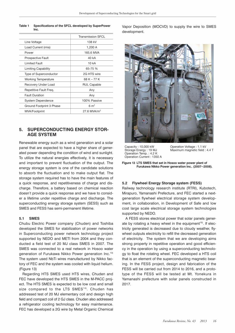
SFCL presents low impedance when operating at a low current at its superconducting state during steady state condition, but its impedance rises quickly when operating at normal conductivity during fault condition.
Conventional relay has a certain delay time from the detection to the operation. SFCL can suppress the first wave of the fault current and can reduce maximum cur-rent. FEC has developed the SFCL, called resistive super-conducting fault current limiter, by making use of the tran-sition between superconductivity and normal-conductivity.
FEC group has developed two types of SFCL. One is an SFCL that uses YBCO thin film superconducting plate, and the other is the SFCL that uses 2G HTS wires by SuperPower Inc. (SP) which is Furukawa’s subsidiary company in U.S. Both SFCLs utilize superconducting/nor-mal state transition on the YBCO thin film plates and the 2G wires, respectively. SFCL utilizing the YCBO elements which has a state named superconducting/normal state transition (S/N state transition). This element presents a zero electrical resistance in its normal operation state and a high electrical resistance when an over current exceeds a specific threshold, thus limiting this over current. The SFCL houses multiple YBCO elements in a cryostat which is a sealed container kept at low temperature by liquid nitrogen. Figure 11 shows thin-film superconducting plate (thin film) and conceptual diagram of SFCL. The thin film has been developed by FEC by introducing the process of metal organic deposition (MOD) technology developed by Agency of Industrial Science and Technology (AIST)12). The structure of the thin film consists of an intermediate
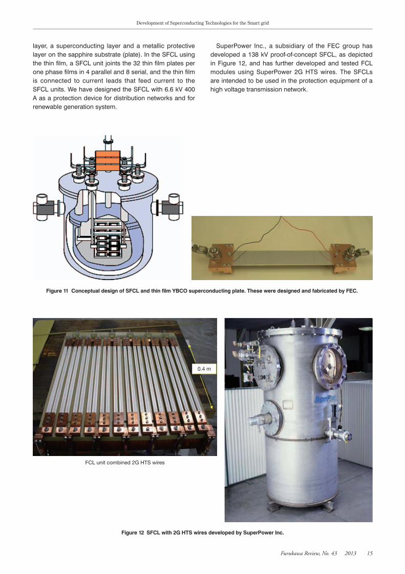
Figure9 Structureofthe275kV3kAHTScable.
HTS conducting layer : 2 layers3 mmW Cu plated YBCO wire
HTS Shield layer : 1 layer5 mmW Cu plated YBCO wire
PP laminated paper
PE shieth O.D. 150 mm
Cu protection layer
Cryostat pipe
Cu stranded former
Figure10 PrincipleofresistiveSFCL(SuppressingFaultCurrent).
Suppressed Fault current with FCL
Fault current without FCL
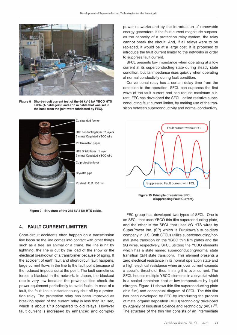
Figure8 Short-circuitcurrenttestofthe66kV-3kAYBCOHTScable(Acablejoint,anda10mcablethatwassetinthebackfromthejointwerefabricatedbyFEC).
Development of Superconducting Technologies for the Smart grid
FurukawaReview,No.43 2013 15
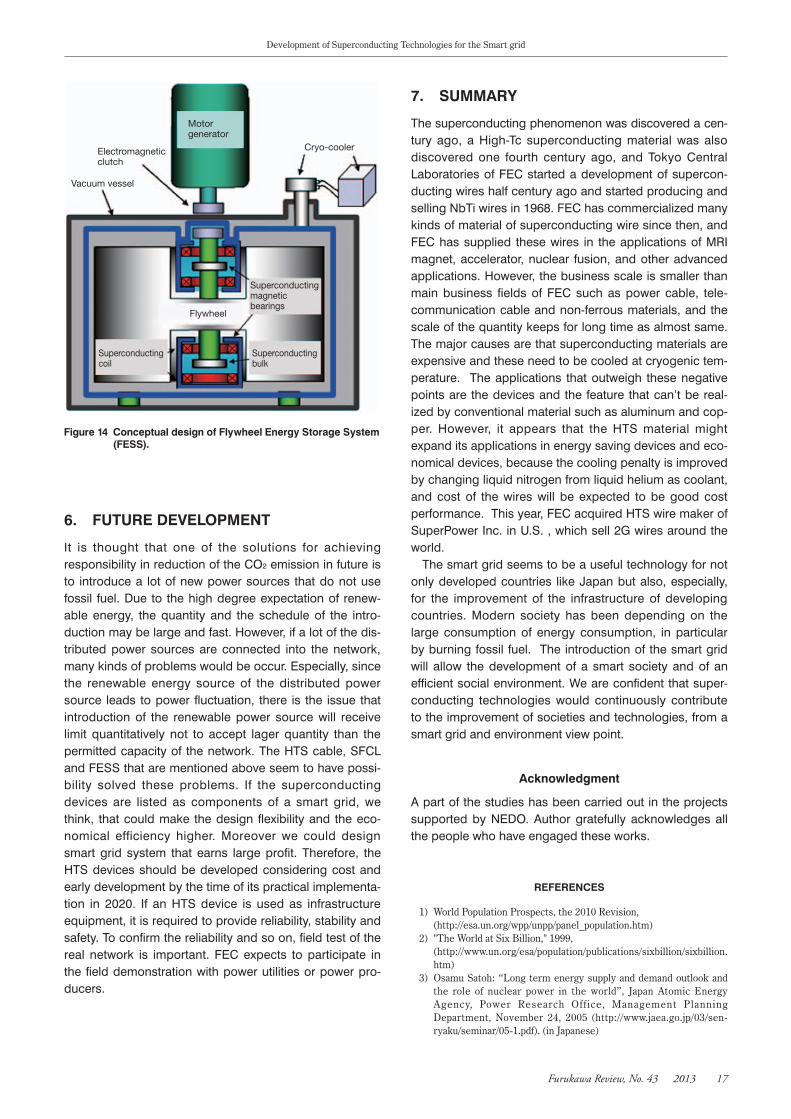
layer, a superconducting layer and a metallic protective layer on the sapphire substrate (plate). In the SFCL using the thin film, a SFCL unit joints the 32 thin film plates per one phase films in 4 parallel and 8 serial, and the thin film is connected to current leads that feed current to the SFCL units. We have designed the SFCL with 6.6 kV 400 A as a protection device for distribution networks and for renewable generation system.
SuperPower Inc., a subsidiary of the FEC group has developed a 138 kV proof-of-concept SFCL, as depicted in Figure 12, and has further developed and tested FCL modules using SuperPower 2G HTS wires. The SFCLs are intended to be used in the protection equipment of a high voltage transmission network.
Figure11 ConceptualdesignofSFCLandthinfilmYBCOsuperconductingplate.TheseweredesignedandfabricatedbyFEC.
Figure12 SFCLwith2GHTSwiresdevelopedbySuperPowerInc.
FCL unit combined 2G HTS wires
0.4 m
Development of Superconducting Technologies for the Smart grid
FurukawaReview,No.43 2013 16
5. SUPERCONDUCTINGENERGYSTOR-AGESYSTEM
Renewable energy such as a wind generation and a solar panel that are expected to have a higher share of gener-ated power depending the condition of wind and sunlight. To utilize the natural energies effectively, it is necessary and important to prevent fluctuation of the output. The energy storage system is one of the candidate solutions to absorb the fluctuation and to make output flat. The storage system required has to have the main features of a quick response, and repetitiveness of charge and dis-charge. Therefore, a battery based on chemical reaction doesn’t provide a quick response and we have to consid-er a lifetime under repetitive charge and discharge. The superconducting energy storage system (SESS) such as SMES and FESS has semi-permanent lifetime.
5.1 SMESChubu Electric Power company (Chuden) and Toshiba developed the SMES for stabilization of power networks in Superconducting power network technology project supported by NEDO and METI from 2004 and they con-ducted a field test of 20 MJ class SMES in 2007. The SMES was connected to a real network in Hosoo water generation of Furukawa Nikko Power generation Inc.13)
The system used NbTi wires manufactured by Nikko fac-tory of FEC and the system was cooled with liquid helium. (Figure 13)
Regarding HTS SMES used HTS wires, Chuden and FEC have developed the HTS SMES in the M-PACC proj-ect. The HTS SMES is expected to be low cost and small size compared to the LTS SMES14). Chuden has addressed test of 20 MJ elementary coil and design high field and compact coil of 2 GJ class. Chuden also addressed a refrigerator cooling technology for easy maintenance. FEC has developed a 2G wire by Metal Organic Chemical
Vapor Deposition (MOCVD) to supply the wire to SMES development.
5.2 FlywheelEnergyStoragesystem(FESS)Railway technology research institute (RTRI), Kubotech, Mirapuro, Yamanashi Prefecture, and FEC started a next-generation flywheel electrical storage system develop-ment, in collaboration, in Development of Safe and low cost large scale electrical storage system technologies supported by NEDO.
A FESS stores electrical power that solar panels gener-ate by rotating a heavy wheel in the equipment15). If elec-tricity generated is decreased due to cloudy weather, fly-wheel outputs electricity to refill the decreased generation of electricity. The system that we are developing aims strong property in repetitive operation and good efficien-cy in the operation by using a superconducting technolo-gy to float the rotating wheel. FEC developed a HTS coil that is an element of the superconducting magnetic bear-ing. In the FESS project, design and fabrication of the FESS will be carried out from 2014 to 2016, and a proto-type of the FESS will be tested at Mt. Yonekura in Yamanashi prefecture with solar panels constructed in 2017.
Table1 SpecificationsoftheSFCLdevelopedbySuperPowerInc.
Transmission SFCL
Line Voltage 138 kV
Load Current (rms) 1,200 A
Power 165.6 MVA
Prospective Fault 40 kA
Limited Fault 10 kA
Limiting Capability 65-75 %
Type of Superconductor 2G HTS wire
Working Temperature 68 K – 77 K
Recovery Under Load RUL Capable
Repetitive Fault Freq. Any
Fault Duration Any
System Dependence 100% Passive
Ground Footprint 3 Phase 6 m2
MVA/Footprint 27.6 MVA/m2
Figure13 LTSSMESthatsetinHosoowaterpowerplantofFurukawaNikkoPowergenerationInc..(2007~2008).
Capacity : 10,000 kWStorage Energy : 19 MJOperation Temp. : 4.2 KOperation Current : 1350 A
Operation Voltage : 1.1 kVMaximum magnetic field : 4.4 T
Development of Superconducting Technologies for the Smart grid
FurukawaReview,No.43 2013 17
6. FUTUREDEVELOPMENT
It is thought that one of the solutions for achieving responsibility in reduction of the CO2 emission in future is to introduce a lot of new power sources that do not use fossil fuel. Due to the high degree expectation of renew-able energy, the quantity and the schedule of the intro-duction may be large and fast. However, if a lot of the dis-tributed power sources are connected into the network, many kinds of problems would be occur. Especially, since the renewable energy source of the distributed power source leads to power fluctuation, there is the issue that introduction of the renewable power source will receive limit quantitatively not to accept lager quantity than the permitted capacity of the network. The HTS cable, SFCL and FESS that are mentioned above seem to have possi-bility solved these problems. If the superconducting devices are listed as components of a smart grid, we think, that could make the design flexibility and the eco-nomical efficiency higher. Moreover we could design smart grid system that earns large profit. Therefore, the HTS devices should be developed considering cost and early development by the time of its practical implementa-tion in 2020. If an HTS device is used as infrastructure equipment, it is required to provide reliability, stability and safety. To confirm the reliability and so on, field test of the real network is important. FEC expects to participate in the field demonstration with power utilities or power pro-ducers.
7. SUMMARY
The superconducting phenomenon was discovered a cen-tury ago, a High-Tc superconducting material was also discovered one fourth century ago, and Tokyo Central Laboratories of FEC started a development of supercon-ducting wires half century ago and started producing and selling NbTi wires in 1968. FEC has commercialized many kinds of material of superconducting wire since then, and FEC has supplied these wires in the applications of MRI magnet, accelerator, nuclear fusion, and other advanced applications. However, the business scale is smaller than main business fields of FEC such as power cable, tele-communication cable and non-ferrous materials, and the scale of the quantity keeps for long time as almost same. The major causes are that superconducting materials are expensive and these need to be cooled at cryogenic tem-perature. The applications that outweigh these negative points are the devices and the feature that can’t be real-ized by conventional material such as aluminum and cop-per. However, it appears that the HTS material might expand its applications in energy saving devices and eco-nomical devices, because the cooling penalty is improved by changing liquid nitrogen from liquid helium as coolant, and cost of the wires will be expected to be good cost performance. This year, FEC acquired HTS wire maker of SuperPower Inc. in U.S. , which sell 2G wires around the world.
The smart grid seems to be a useful technology for not only developed countries like Japan but also, especially, for the improvement of the infrastructure of developing countries. Modern society has been depending on the large consumption of energy consumption, in particular by burning fossil fuel. The introduction of the smart grid will allow the development of a smart society and of an efficient social environment. We are confident that super-conducting technologies would continuously contribute to the improvement of societies and technologies, from a smart grid and environment view point.
Acknowledgment
A part of the studies has been carried out in the projects supported by NEDO. Author gratefully acknowledges all the people who have engaged these works.
REFERENCES
1) World Population Prospects, the 2010 Revision, (http://esa.un.org/wpp/unpp/panel_population.htm) 2) "The World at Six Billion," 1999, (http://www.un.org/esa/population/publications/sixbillion/sixbillion.
htm) 3) Osamu Satoh: “Long term energy supply and demand outlook and
the role of nuclear power in the world”, Japan Atomic Energy Agency, Power Research Office, Management Planning Department, November 24, 2005 (http://www.jaea.go.jp/03/sen-ryaku/seminar/05-1.pdf). (in Japanese)
Figure14 ConceptualdesignofFlywheelEnergyStorageSystem(FESS).
Motor generator
Electromagnetic clutch
Vacuum vessel
Flywheel
Superconducting magnetic bearings
Cryo-cooler
Superconducting bulk
Superconducting coil

Development of Superconducting Technologies for the Smart grid
FurukawaReview,No.43 2013 18
4) Miura, et. al.: Proceedings of the 7th Annual Conference of Power & Energy Society. IEE of Japan (1995) 556. (in Japanese)
5) Mukoyama et.al.: The Development of a 66 kV-class High-Tc Superconducting Cable [in Japanese], Cryogenic engineering. Journal of the Cryogenic Society of Japan 33(3), 137-144, March 25, 1998.
6) K. Ueda et al.: Physica C 392-396 (2003) 1171 7) Yagi,et. al.: Sccessful Field Testing Result of the World’s Longest
500-m High Tc Superconducting Power Cable, Furukawa Review No.28 ,August 2005.
8) Mukoyama, et.al.: Development of YBCO High-Tc Superconduction Power Cables, Furukawa Review No.35, March 2010.
9) Mukoyama, et.al.: Development of 275 kV Superconducting Cable, Study Commotty Document, The Papers of Technical Meeting on Application of Superconductivity, IEE Japan
10) S. Mukoyama et.al.: “DEVELOPMENT OF 275 KV 3 KA HTS POWER CABLE”, 8th International Conference on Insulated Power Cables. C.6.2. Jicable'11, C.6.2, 2011
11) S. Mukoyama et.al.: “Status of a 275 kV class REBCO Superconducting Cable Development”, Applied Superconductivity Conference 2004, No. 3LB04, 2012
12) T. Manabe et.al.: Preparation of high-Jc large-size YBCO films (30 × 10 cm2) by coating-pyrolysis process on CeO2-buffered sap-phire”, Physica C, 412-414, pp. 896-899, 2004
13) Verification Test and Development Status of SMES in Actual System, Technological Development News No.131, Chubu Electric, July 2008. (in Japanese)
14) Shigeo Nagaya, et.al.: Technology Development Status of Yttrium Based Coil for SMES, Journal of Cryogenics and Superconductivity Society of Japan 46-6 (2011), 327-334. (in Japanese)
15) Research &Development of Flywheel Power Storage Device for Railway Using Superconducting Magnetic Bearings, Railway Technical Research Institute Homepage (http://www.rtri.or.jp/rd/division/rd79/rd7920/rd79200107.html). (in Japanese)