development of vfd, plc and scada based fluid temperature
TRANSCRIPT

Proceedings of the 2nd International Conference on Industrial and Mechanical Engineering and Operations Management (IMEOM), Dhaka, Bangladesh. December 12-13, 2019
© IEOM Society International
Development of VFD, PLC and SCADA Based Fluid Temperature, Pressure and Level Control for Food
Manufacturing Industry Abu Salman Shaikat and Md. Mizanur Rahman and Mehbub Khan and Mohd Habibul
Kabir Nouman and Suraiya Akter Department of Mechatronics Engineering
World University of Bangladesh Dhaka, Bangladesh
[email protected], [email protected], [email protected], [email protected],[email protected]
Abstract
Food industries are mainly focused on the exact temperature and pressure of chemicals and water levels due to maintaining the quality and government rules. This paper deals with the concept of accurate fluid temperature and pressure system, which in-turns help to get the desired output for food industrial purpose. This paper aims to implement a controlling and monitoring system of fluid level, temperature, and pressure using VFD by PLC along with SCADA and PID. For the Food industry, to acquire variable fluid pressure and density, it needs to maintain the pump-motor liquid quantitatively, which is focused on our proposed system. Low/high-pressure level detection factors make VFDs superior to mechanical devices for regulating pump flow. VFD is employed to control the speed of pump-motor so that the required level and pressure can be achieved. Also, the temperature sensor is used to detect the temperature of the liquid. The implementation of a hardware and software for speed control, temperature control, pressure control, parameter monitoring on SCADA and WinCC RT Advanced screen is provided.
Keywords Fluid Temperature, pressure, level, PLC, SCADA, VFD, WinCC RT advanced, pump-motor.
1. IntroductionMotor speed control is the key of efficiency of energy. Around 60% of all electrical energy used in worldwide operates flow loads such as pumps, fans, blowers and compressors, mostly powered by variable speed induction motors, which is presented by Kory K. An external means of adjustment is neededwhen output flow requirements fluctuate in such systems. Fixed-speed pumps gives nearly full horsepower and consume nearly maximum energy full time, regardless of demand. The purpose of the VFD, which is described byDhammadip Wasniket al. and Rinchen Geongmit Dorjee, which is installed on water pump-motor (Riza Gürbüz and Tory K)is to increase or decrease the speed of the motor in order to control (increase or decrease) water flow rate in the food industry. Using a variable frequency drive to control the flow means no additional restriction is added to the piping. The key focus of the paper is to flow a variable liquid pressure and specific temperature. Although, to get variable pressure and density of the liquid at the same time we need to keep level in high or low position. We can derive this from the below equation:
P=ƿgh (1) Where, P=pressure, ƿ=density, g= gravity, h=height/level So, for obtaining an accurate density of the fluid, it needs to put an accurate amount of pressure with exact height. Two-speed terms is being used in the motor which are normal and rated speed. Normal speed is the speed at which a motor’s magnetic field rotates if there was no load on the shaft and friction in the bearings (Aung Zaw Latt et al.). Normal speed is calculated by equation, Normal Speed = 120 x F (frequency)/Np (Number of Poles)
This paper focused on the implementation of the smooth driving of the pump-motor to get a perfect flow rate of liquid and temperature controlling system which is controlled by PID (Proportional Integral & Derivative controller) controlling system and PLC (Programmable Logic Controller) and monitored by SCADA (R.Colbaughet al. and Tom
152

Proceedings of the 2nd International Conference on Industrial and Mechanical Engineering and Operations Management (IMEOM), Dhaka, Bangladesh. December 12-13, 2019
© IEOM Society International
artman et al.). In this work, Pump-motor whose speed is varied by VFD is used to flow the liquid from storage to the main tank in the desired output for the purpose of accurate pressure, level switch is used to detect the level of liquid in the tank and temperature sensor is used to detect the temperature of the liquid. Rotary encoders generate pulses, where the number of pulses can be a measure of speed. We used VFD with encoder to adjust the parameters of the count in hardware configuration for controlling the frequency measurement and adjust the parameters of PID control to obtain the determine speed in PLC programming. PID controlling system is used to control the whole operation and WinCC (RT Advanced)(Luis Garcia et al.) is used to display the condition of the process and graphical representation of temperature changes. 2. Proposed Model This process used for product quality and consistency depend on require density of water and require temperature in the food industry. In this automatic controlling and detection system, a PLC CPU is connected with VFD, Level switch and Temperature controller. VFD has an output control system. Level switches and temperature has input and output control system. Variable Frequency Drive (VFD) will control the fluctuation of pump-motor for require flow rate. The higher and lower level of water by given data will be controlled by the Level switch. the level of water of the main tank will be identified by the level rod which is connected with PLC. On the other hand, Temperature controller controls the temperature of water. The thermocouple is used to detect the temperature of water which is connected with the temperature controller. In this system, the analog output from the pump motor will be transmitted to the PLC by the feedback system. level switch and temperature controller has a digital input signal. The solenoid valve is used to exhaust hot water from the main tank. It is connected to the PLC CPU which has an input/output control system. For controlling the VFD, temperature and level SET value, Proportional Integral Derivative (PID) control method has been used. Figure 1 represents the block diagram of PLC and SCADA based level and temperature controlling system in the food industry.
Figure 1: Block Diagram of PLC and SCADA Based Controlling and Monitoring System of Fluid Level,
Temperature and Pressure Using VFD
Figure 2 represents the mechanical design of PLC and SCADA based controlling and monitoring system of fluid level, temperature and pressure using VFD in food industry. For precise pressure detection, an outlet is created in reservoir using equation (1), which is computed from liquid level in reservoir and the density of liquid.
153

Proceedings of the 2nd International Conference on Industrial and Mechanical Engineering and Operations Management (IMEOM), Dhaka, Bangladesh. December 12-13, 2019
© IEOM Society International
Figure 2: Mechanical Design
Figure 3 shows the circuit diagram of PLC and SCADA based controlling and monitoring system of fluid level, temperature and pressure using VFD in food industry. Temperature controller, level switch, PLC, relays, pump, heater and solenoid valve are connected as in Figure 3.
Figure 3: Circuit Diagram
Figure 4 shows the flow Chart of PLC and SCADA based controlling and monitoring system of fluid level, temperature and pressure using VFD in the food industry. Before the system begins, we have to set the input value of pump-motor and set the set value of the temperature of the liquid. Then the system begins (pressing start button), pump-motor will start to flow the liquid in the required amount of flow rate and we observe the liquid level. Firstly, we will keep the liquid level less than the required level, solenoid valve and heater will stay inactivated whereas pump-motor will try to fill up the main tank. Later than, keeping the required liquid level, the heater will start heating the liquid. In that condition, the solenoid valve will stay inactivated and Heater will stay ON until the temperature obtains the temperature set value. As soon as the temperature reaches the set value, the heater will be OFF and continue the set value for 10 seconds. After 10 seconds solenoid valve and pump-motor will be reactivated and heated water will pass through the solenoid valve in required pressure to the food processing area. Finally, the
154

Proceedings of the 2nd International Conference on Industrial and Mechanical Engineering and Operations Management (IMEOM), Dhaka, Bangladesh. December 12-13, 2019
© IEOM Society International
process will end and give feedback to the starting point. The whole process will be displayed via SCADA in the display unit.
Figure 4: Flow Chart
3. Experimental Details As for food process in a food industry, some mechanical components are needed. These components should have the capacity to control whole process. For a food industry, heavy pump-motor is generally used which can supply 3.65m3/hour water or cool liquid per minute. For supplying accurate pressure, the required pressure and fluid flow rate should be taken into consideration.Very few of food industry in Bangladesh are using such kind of process. Therefore, we have collected the data and specification from Thaiindustries. Accurate liquid pressure supply parameters and used in our experiment. Table 1 shows the specification of industrial and experimental parameters for our work.
Table 1: Experimental Data
155

Proceedings of the 2nd International Conference on Industrial and Mechanical Engineering and Operations Management (IMEOM), Dhaka, Bangladesh. December 12-13, 2019
© IEOM Society International
4. Results and DiscussionIn temperature and level controlling system; heater is attached with main tank which is controlled by PLC and SCADA. Liquid level is controlled by VFD through pump-motor and pump-motor is connected by pipes with the main tank and reserve tank. Thermocouple and level detector rods are attached to the main tank. PLC CPU, VFD, pump-motor, Temperature controller, level switches are connected with one another through wire. Three relays are connected with PLC as output. It is connected with heater, pump-motor and solenoid valve as well. Experimental setup without VFD is shown in Figure 5.
Figure 5: Hardware setup of experimental setup without VFD
A motor is linked with rotary encoder by a coupler. The rotary encoder is attached with a wood stand which is attached with plywood card by screws. The analog output module is attached with the programmable logic controller (PLC). A motor, and programmable logic controller (PLC), variable frequency drive (VFD), 24V 4.5A Single Output Switching power supply is attached on a plywood board by screws. Figure 6 shows the hardware setup of a PLC and SCADA based speed control and monitoring system using variable frequency drive (VFD).
Figure 6: Hardware Setup of VFD
A temperature controller is attached with PLC CPU 1212 AC/DC/RLY and current temperature is displayed. A set value can be set in this controller. Firstly, we reset the total temperature controller so as toerase any previous record. Then, temperature set value has been set from the 'SET' option. When the required temperature value is displayed,
156

Proceedings of the 2nd International Conference on Industrial and Mechanical Engineering and Operations Management (IMEOM), Dhaka, Bangladesh. December 12-13, 2019
© IEOM Society International
then we set that and 'ALM 1' turns 'ON'. We have fixed the SET value as 43ºC. Figure 7 shows the setting of 'SET' value.
Figure 7: Setting the 'SET' Value
After setting the “SET” value, the switch is turned on from 'System ON' button. In that case, switch is colored as green according to Figure 9. If the system needs to be off manually, then the red button should be pressed.In Figure 8, it is shown that, motor is ON. Water is supplied from reservoir to main tank. Motor will remain turned ON until the water level reachesits“SET” value.
Figure 8: Motor ON and water supplied from reservoir to main tank
In the following Figure, observation table is shown in motor running mode. When motor is ON, other devices and detection system are in OFF condition. All the green alarms represents running mode whereas the red alarms represents stop mode. Figure 9signifies the observation of run mode.
Figure 9: Observation of run mode in WinCC RT advanced As water level reaches to its “SET” value and motor has stopped. After reaching the SET value, water supply stops the supply process from reserve tank.Then, the Heater is turned ON.Figure 10 shows the running mode condition when motor stops and heater turns ON in WinCC RT advanced.
157

Proceedings of the 2nd International Conference on Industrial and Mechanical Engineering and Operations Management (IMEOM), Dhaka, Bangladesh. December 12-13, 2019
© IEOM Society International
Figure 10: Running Mode when motor stops and heater goes On in WinCC RT advanced When heater is ON, it will take time to heat water to reach its set value. It will continue heating until it reaches stable position of “SET” value. Figure 11 confirms the condition when temperature reaches its SET value.
Figure 11: Temperature Reaching Its “SET” Value
Figure 12illustrates the running mode conditionas heater stops to heat and temperature reaches its set value in stable position. Here heater, motor and solenoid valve is in OFF position.
Figure 12: In Running Mode When Heater Stops and Temperature Reaches Its SET Value in WinCC RT advanced When the set value reaches the required temperature and heater is OFF, then solenoid valve will open and motor starts. Heated water will pass from main tank by solenoid valve to exhaust line. Figure 13 show that solenoid valve and motor is ON and figure 14 shows the conditions in web server.
158

Proceedings of the 2nd International Conference on Industrial and Mechanical Engineering and Operations Management (IMEOM), Dhaka, Bangladesh. December 12-13, 2019
© IEOM Society International
Figure 13: Solenoid Valve and motor ON after 10 Seconds
Figure 14: Process continuation when Temperature reaches SET value
Finally, we can observethat the system has stopped the process and all the devices are in OFF state. We can stop the whole process by pushing red button in case of emergency. If we do not need to stop the system, the process will continue in cyclic order. Figure 15 shows the process completionstage when system stops.
Figure 15: Process in OFF state showing in WinCC RT advanced
The speed variation of VFD is shown in Figure 16. Motor will rotate in forward direction all the time and with respect to demand, the speed will change. Figure 16 and 17 demonstrates the level and temperature change graph with time using WinCC RT advanced. According to the results, with time, level also increases. For a set value of level (40 liters), the graph illustrates linearity for a certain period. In this case, after 10
159
Proceedings of the 2nd International Conference on Industrial and Mechanical Engineering and Operations Management (IMEOM), Dhaka, Bangladesh. December 12-13, 2019
© IEOM Society International
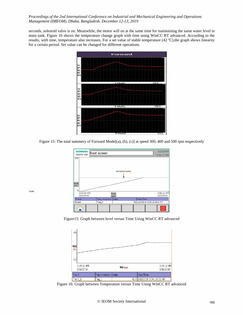
seconds, solenoid valve is on. Meanwhile, the motor will on at the same time for maintaining the same water level in main tank. Figure 16 shows the temperature change graph with time using WinCC RT advanced. According to the results, with time, temperature also increases. For a set value of stable temperature (42 ºC),the graph shows linearity for a certain period. Set value can be changed for different operations.
Figure 15: The total summery of Forward Mode[(a), (b), (c)] at speed 300, 400 and 500 rpm respectively
Figure15: Graph between level versus Time Using WinCC RT advanced
Figure 16: Graph between Temperature versus Time Using WinCC RT advanced
160

Proceedings of the 2nd International Conference on Industrial and Mechanical Engineering and Operations Management (IMEOM), Dhaka, Bangladesh. December 12-13, 2019
© IEOM Society International
4. ConclusionIn this work, a PLC-SCADA system has been developed where a Real time monitoring and controlling of the process has been carried out. The speed of pump-motor can be changed from VFD as we can control the timing of filling water level. Through this process, various set points like 30-55⁰C have been checked. From temperature controller we can change the value of temperature and can see the current value when rising up the value in the time of heating. The level measured points can be fixed mechanically for further process. The motor is controlled with some automated systems and becomes the work very easier and the output is represented by using display. All the real time values were obtained Using WinCC RT Advanced. This project is very useful for food industry and also useful in chemical industry.
References Dhammadip Wasniket al., Speed Control of Induction Motor using Variable Frequency Drives and PLC,
International Journal of Advanced Research in Electrical, Electronics and Instrumentation Engineering, Vol. 6, Issue 6, 2017.
Riza Gürbüz, Controlling Flow Rate and Fluid Level by Variable Frequency Drive Unit, The Archieve of Mechanical Engineering, volume-LVII, 10.2478/v10180-010-0022-y, number-4, 2010.
Tory K, Pump Control with Variable Frequency Drives, Pumps & System, June 2008. Rinchen Geongmit Dorjee, Monitoring and Control of a Variable Frequency Drive Using PLC and SCADA,
International Journal on Recent and Innovation Trends in Computing and Communication, vol. 2, no. 10, 2014. R. Colbaugh; E. Barany ; K. Glass, Identification of SCADA systems: case studies, 38th IEEE Conference on
Decision and Control (Cat. No. 99CH36304), December 1999.Tom Bartman , Kevin Carson, Securing communications for SCADA and critical industrial systems, 69th Annual
Conference for Protective Relay Engineers (CPRE), April 2016. Luis Garcia, Saman Zonouz, Dong Wei, Leandro Pfleger de Aguiar, Detecting PLC control corruption via on-device
runtime verification:, 2016 Resilience Week (RWS), 2016.Julian Henderson, “The Raw Materials of Early Glass Production, Oxford Journal of Archeology, 1985.
Aung Zaw Latt, Ni Ni Win, Variable Speed Drive of Single Phase Induction Motor Using Frequency Control Method, 2009 International Conference on Education Technology and Computer, 2009.
Biographies
Abu Salman Shaikat is a Lecturer in Department of Mechatronics Engineering at the World University of Bangladesh, Dhaka, Bangladesh. He earned his B.Sc. in Electrical and Electronics Engineering from Ahsanullah University of Science and Technology, M.Eng.degree in Mechatronics Engineering from Asian Institute of Technology. He worked at Bangkok Glass Public Company Limited as a Production Engineer, AIT Extension, IT and Engineering Unit as a Service Provider and Dowla Consultants and Engineering Limited as an Electrical Design Engineer. His research interest includes Automation, Robotics, Artificial Intelligence, Product Design and Development, Control System, Image Processing and Deep Learning.
Md. Mizanur Rahman is chartered Energy Engineer who is now working as an Associate Professor under World University of Bangladesh. He also worked as a Research Assistant, a Research Engineer, and a consultant in the Renewable Energy Technology in Asia (RETs in Asia) project at KUET and AIT until 2004, December. After that, he moved as a Program Support Specialist under a NGO named BRAC Bangladesh. He was joined as Assistant Manager in the Rural Power Company Ltd (RPCL) in February 2006 and continued until July 2007. He started PhD on Natural Draft Chimney at Universiti Malaysia Sabah from July 2007. He was worked as a lecturer in the TAS institute of Oil and Gas from July 2009 and continue until August 2012 then moved Universiti Malaysia Sabah as Senior Lecturer.
Mehbub Khan is currentlyworking with Confidence Power Limited as Trainee Engineer. He studied in Department of Mechatronics Engineering at World University of Bangladesh.
Mohd Habibul Kabir Nouman studied in Department of Mechatronics Engineering at World University of Bangladesh.
Suraiya Akter is currently studying in Department of Mechatronics Engineering at World University of Bangladesh.
161