developments toward an autonomous robotic … · developments toward an autonomous robotic crane...
TRANSCRIPT

Developments toward an Autonomous Robotic Crane for Automated Steel Construction
Kamel S. Saidi, Alan M. Lytle, William C. Stone, Nicholas A. Scott
Abstract-- The NIST Construction Metrology and Automation Group, in cooperation with the NIST Intelligent Systems Division, is researching robotic structural steel placement as part of a project to develop an Automated Steel Construction Testbed. This project was initiated in response to industry requests for advanced tools and methodologies to speed the erection of steel structures while maintaining or enhancing standards for worker safety and facility reliability. This initial effort integrates and extends prior NIST research in robotic crane employment, tele-operated steel beam placement, laser-based site metrology, construction component tracking, and web-enabled 3-D visualization. Index terms-- construction automation, path planning, robotics, VRML, 3-D coordinate measurement systems
I. INTRODUCTION The American Institute of Steel Construction (AISC) recently expressed a need for reducing steel structure erection time by 25% [1]. In response, the Construction Metrology and Automation Group (CMAG) at the National Institute of Standards and Technology (NIST) is developing a robotic crane system for automated steel construction. This effort is the first phase of CMAG’s Automated Steel Construction Testbed (ASCT) project and extends prior NIST research in construction component tracking [2] and real-time construction metrology [3]. This work also continues efforts in tele-operated steel beam placement [4] to include autonomous control of a six degree-of-freedom (DOF) robotic crane. The base platform for the ASCT is an inverted Stewart platform parallel link manipulator [5] known as the NIST RoboCrane. RoboCrane’s Real-Time Control System [6] (RCS) is supplemented with Cartesian position feedback from a laser-based site measurement system (SMS) for trajectory planning and dynamic control. The Robot’s and the construction components’ positions are represented in a virtual world model of the construction operation for visualization and control. The structure to be assembled consists of a steel beam and two steel columns connected with the ATLSS1 quick
connector. The ATLSS [7] connector was chosen due to its simple, drop-in operational principle.
II. SYSTEM OVERVIEW The current configuration of the ASCT is made up of the following five primary components (the first 3 components are briefly described below, while the reader is referred to [8, 9] for a description of the last 2 components, respectively): 1. RoboCrane 2. Site Measurement System 3. High-level Controller 4. Component Tracking System 5. Visualization System
A. RoboCrane RoboCrane is an innovative, cable-driven, manipulator invented by the NIST Intelligent Systems Division (ISD) and further developed and adapted for specialized applications over a period of several years [10, 11, 12]. The basic RoboCrane is an inverted Stewart platform parallel-link manipulator with cables and winches serving as the links and actuators, respectively. The moveable platform, or “lower triangle,” is kinematically constrained by maintaining tension in all six cables that terminate in pairs at the vertices of an “upper triangle” formed by the cable support points. This arrangement provides improved load stability over traditional lift systems and enables 6 DOF payload control. The version of RoboCrane used in this project is the Tetrahedral Robotic Apparatus (TETRA). In the TETRA configuration, all winches, amplifiers, and motor controllers are located on the moveable platform. The upper triangle only provides the three tie points for the TETRA cables, allowing the device to be retrofitted to existing overhead lift mechanisms.
NIST, BFRL, Construction Metrology and Automation Group, Mail Stop 8611, Gaithersburg, MD 20899-8611; [email protected], [email protected], [email protected], [email protected]. 1. Certain commercial equipment, instruments, or materials are identified in this report in order to specify the experimental procedure adequately. Such identification is not intended to imply recommendation or endorsement by
the National Institute of Standards and Technology, nor is it intended to imply that the materials or equipment identified are necessarily the best available for the purpose.

B. Site Measurement System The SMS consists of a commercially available positioning technology that uses stationary, active-beacon laser transmitters and mobile laser detectors to provide millimeter-level position data. Each transmitter rotates two fanned laser beams (eye-safe) and also emits an infrared, omni-directional timing pulse. The elevation of a detector is calculated from the time difference between fan strikes. The azimuth of a detector is referenced from the timing pulse. The field of view of each transmitter is approximately 290° in azimuth and +/- 30° in elevation/declination. Line-of-sight between a detector and at least two transmitters must be maintained in order to calculate a position. Each detector can track up to four transmitters and wirelessly transmit timing information to a base computer for position calculation. The manufacturer-recommended minimum and maximum operating ranges from each transmitter are 5 m and 50 m, respectively. The SMS includes four transmitters positioned around the work site and 3 detectors mounted on RoboCrane (see Figure 1). Position data from the three detectors are used to calculate RoboCrane’s pose (position and orientation). For convenience, all measurements are calculated in the local SMS coordinate frame and mapped to RoboCrane’s fixed coordinate frame. Position data are polled at approximately 7 Hz using a NIST-developed data communications application. In addition to the three mobile detectors described above, the SMS also includes a self-contained digitizing tool with two identical optical detectors mounted at a known distance apart on a rigid pole. Knowing the precise length of the pole and calculating the vector projection along the line formed by the two detectors allows accurate calculation of the 3-D coordinate of the pole’s tip within the SMS coordinate system. By measuring a number of points on a steel beam or column using this digitizing tool, the beam or column’s position and orientation can also be calculated within the SMS’s coordinate system.
C. High-level Controller A high-level, software-based controller is being developed to provide the following functions for the overall system. • Sensor fusion • Pose estimation • Path planning • World model database maintenance • User interface The NIST RoboCrane was previously tele-operated using a graphical user interface and a spaceball (a 3-D joystick). Feedback to the operator was provided in the form of a live video feed from cameras mounted on and around the robot as well as through an estimation of the robot’s pose (relative
to a known home pose) that relied on data from encoders built into the robot’s 6 winches (i.e., dead-reckoning) [13]. This type of feedback is suitable for tele-operation, however, the inherent drift in subsequent pose determinations rules out autonomous control unless the robot is frequently re-calibrated in order to maintain an accurate current pose estimate. In order to achieve autonomous control, the SMS was installed on RoboCrane as described above. However, since the SMS can only update the robot’s pose at a maximum rate of 7 Hz, real-time feedback control cannot be achieved by relying solely on the SMS data. Therefore, real-time motion was achieved by driving the robot using the encoder-based pose estimate in the feedback loop and by periodically stopping the robot at preset waypoints and updating the pose using the SMS data. Figure 2 presents the overall structures of the RoboCrane controller and the high-level controller that was developed to function on top of the existing controller. The high-level controller receives encoder data from the RoboCrane controller and compares them with data from the SMS. The high-level controller then sends back velocity commands that move RoboCrane. The RoboCrane controller, a version of the NIST Real-time Control System implemented in the early 1990’s, converts these velocity commands to winch controller inputs that effect the desired movement. Closed-loop position feedback from the SMS-calculated pose enables periodic modification of the path until the desired target pose is reached. The position of RoboCrane calculated using the SMS enables us to characterize the drift in the robot’s current encoder-based pose and to adjust for it. Currently this adjustment is made by assuming that the SMS-provided robot pose is more accurate than the encoder-based pose (figures for these accuracies are currently under investigation). Thus, the robot’s best pose estimate is calculated by simply subtracting the calculated drift from the encoder-based pose1. RoboCrane’s pose within the construction site will be maintained in a world model database that will also include the pose estimates of all relevant construction components. Based on world model component locations and RoboCrane’s current pose and operating limits, a series of waypoints will be calculated that will move the robot into a desired target pose. The required transformations and corresponding Cartesian velocity commands (Translation: x, y, z; Rotation: roll, pitch, yaw) are calculated and sent to 1 In future work, more sensors will be incorporated for measuring the crane’s pose and the pose of the various construction components on the site. High frame-rate LADAR as well as differential GPS are some of the sensors under consideration by CMAG. In addition, we also plan to incorporate a more sophisticated sensor fusion technique such as Kalman filtering once we have a better characterization of the various sensors’ performance.
the RoboCrane controller via a communications interface. A VRML-based 3-D visualization system will also be used to provide remote visual feedback to an operator or supervisor (see Figures 3 and 4). Elements of the world model – the construction plane, RoboCrane, and the target components – will be modeled in VRML 97 [14] and displayed within a browser environment giving an observer 3-D “fly-through” review capability. A socket connection between the ASCT controller and the VRML environment will provide pose updates for RoboCrane, components being moved, and other elements of interest. The VRML object models within the visualization system will then be repositioned by a Java applet using the External Authoring Interface browser extension. This provides a non-proprietary, open standard, low-bandwidth method of displaying a 3-D representation of robot operations within the work site.
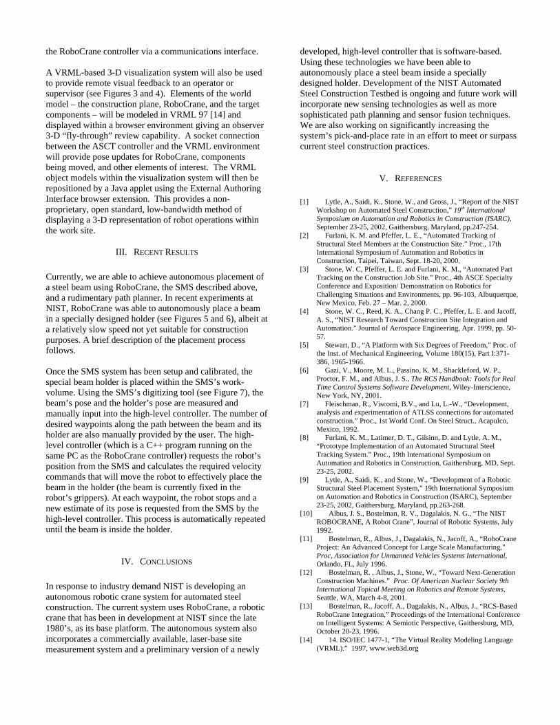
III. RECENT RESULTS Currently, we are able to achieve autonomous placement of a steel beam using RoboCrane, the SMS described above, and a rudimentary path planner. In recent experiments at NIST, RoboCrane was able to autonomously place a beam in a specially designed holder (see Figures 5 and 6), albeit at a relatively slow speed not yet suitable for construction purposes. A brief description of the placement process follows. Once the SMS system has been setup and calibrated, the special beam holder is placed within the SMS’s work-volume. Using the SMS’s digitizing tool (see Figure 7), the beam’s pose and the holder’s pose are measured and manually input into the high-level controller. The number of desired waypoints along the path between the beam and its holder are also manually provided by the user. The high-level controller (which is a C++ program running on the same PC as the RoboCrane controller) requests the robot’s position from the SMS and calculates the required velocity commands that will move the robot to effectively place the beam in the holder (the beam is currently fixed in the robot’s grippers). At each waypoint, the robot stops and a new estimate of its pose is requested from the SMS by the high-level controller. This process is automatically repeated until the beam is inside the holder.
IV. CONCLUSIONS In response to industry demand NIST is developing an autonomous robotic crane system for automated steel construction. The current system uses RoboCrane, a robotic crane that has been in development at NIST since the late 1980’s, as its base platform. The autonomous system also incorporates a commercially available, laser-base site measurement system and a preliminary version of a newly
developed, high-level controller that is software-based. Using these technologies we have been able to autonomously place a steel beam inside a specially designed holder. Development of the NIST Automated Steel Construction Testbed is ongoing and future work will incorporate new sensing technologies as well as more sophisticated path planning and sensor fusion techniques. We are also working on significantly increasing the system’s pick-and-place rate in an effort to meet or surpass current steel construction practices.
V. REFERENCES [1] Lytle, A., Saidi, K., Stone, W., and Gross, J., “Report of the NIST
Workshop on Automated Steel Construction,” 19th International Symposium on Automation and Robotics in Construction (ISARC), September 23-25, 2002, Gaithersburg, Maryland, pp.247-254.
[2] Furlani, K. M. and Pfeffer, L. E., “Automated Tracking of Structural Steel Members at the Construction Site.” Proc., 17th International Symposium of Automation and Robotics in Construction, Taipei, Taiwan, Sept. 18-20, 2000.
[3] Stone, W. C, Pfeffer, L. E. and Furlani, K. M., “Automated Part Tracking on the Construction Job Site.” Proc., 4th ASCE Specialty Conference and Exposition/ Demonstration on Robotics for Challenging Situations and Environments, pp. 96-103, Albuquerque, New Mexico, Feb. 27 – Mar. 2, 2000.
[4] Stone, W. C., Reed, K. A., Chang P. C., Pfeffer, L. E. and Jacoff, A. S., “NIST Research Toward Construction Site Integration and Automation.” Journal of Aerospace Engineering, Apr. 1999, pp. 50-57.
[5] Stewart, D., “A Platform with Six Degrees of Freedom,” Proc. of the Inst. of Mechanical Engineering, Volume 180(15), Part I:371-386, 1965-1966.
[6] Gazi, V., Moore, M. L., Passino, K. M., Shackleford, W. P., Proctor, F. M., and Albus, J. S., The RCS Handbook: Tools for Real Time Control Systems Software Development, Wiley-Interscience, New York, NY, 2001.
[7] Fleischman, R., Viscomi, B.V., and Lu, L.-W., “Development, analysis and experimentation of ATLSS connections for automated construction.” Proc., 1st World Conf. On Steel Struct., Acapulco, Mexico, 1992.
[8] Furlani, K. M., Latimer, D. T., Gilsinn, D. and Lytle, A. M., “Prototype Implementation of an Automated Structural Steel Tracking System.” Proc., 19th International Symposium on Automation and Robotics in Construction, Gaithersburg, MD, Sept. 23-25, 2002.
[9] Lytle, A., Saidi, K., and Stone, W., “Development of a Robotic Structural Steel Placement System,” 19th International Symposium on Automation and Robotics in Construction (ISARC), September 23-25, 2002, Gaithersburg, Maryland, pp.263-268.
[10] Albus, J. S., Bostelman, R. V., Dagalakis, N. G., “The NIST ROBOCRANE, A Robot Crane”, Journal of Robotic Systems, July 1992.
[11] Bostelman, R., Albus, J., Dagalakis, N., Jacoff, A., “RoboCrane Project: An Advanced Concept for Large Scale Manufacturing,” Proc, Association for Unmanned Vehicles Systems International, Orlando, FL, July 1996.
[12] Bostelman, R. , Albus, J., Stone, W., “Toward Next-Generation Construction Machines.” Proc. Of American Nuclear Society 9th International Topical Meeting on Robotics and Remote Systems, Seattle, WA, March 4-8, 2001.
[13] Bostelman, R., Jacoff, A., Dagalakis, N., Albus, J., “RCS-Based RoboCrane Integration,” Proceedings of the International Conference on Intelligent Systems: A Semiotic Perspective, Gaithersburg, MD, October 20-23, 1996.
[14] 14. ISO/IEC 1477-1, “The Virtual Reality Modeling Language (VRML).” 1997, www.web3d.org

Figure 1: Photograph of RoboCrane with the SMS.
Tele-op. UI RoboCrane Controller High-level Controller User
Interface Path
Planner Input Command
Buffer Control Panel
World Model DB
Pose Estimator
Trajectory Planner
Kinematic Model
Spaceball
Sensor Fusion
Pose Estimator
Output Command
PID Controller
Site Measurement System (SMS)
Tetra-based Laser SMS
Barcode Scanner Robot
Laser-based 3D Digitizer
RFID Encoders Motors Servo Amps.
2002 1992
Figure 2: The interface between the ASCT high-level controller and the existing RobCrane controller.

Figure 3: The VRML visualization system showing RoboCrane attempting to dock a steel beam into the special holder.
Figure 4: A closeup of the VRML visualization system showing RoboCrane docking a steel beam into the special holder.
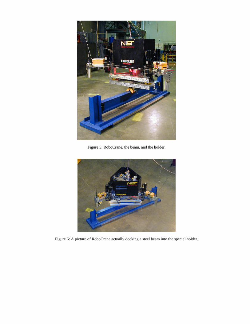
Figure 5: RoboCrane, the beam, and the holder.
Figure 6: A picture of RoboCrane actually docking a steel beam into the special holder.

Figure 7: An operator using the 3D digitizing tool.