dfbx thermo-mechanical review joseph rasson, lbl tom peterson, fermilab cern 24 april 2007
TRANSCRIPT
DFBX Thermo-Mechanical Review
Joseph Rasson, LBL Tom Peterson, Fermilab
CERN24 April 2007
24 April 2007 DFBX 2
DFBX Presentation Outline
• Introduction• Documentation • Flow schematic• Line pressures• Mechanical Test Protocol• Piping and Interface Layouts• Mechanical Loads• Free body and force diagrams• Peak stresses• Transport• Conclusion• Future Activities
24 April 2007 DFBX 3
Introduction
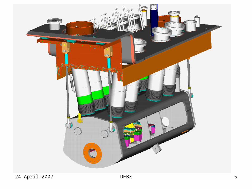
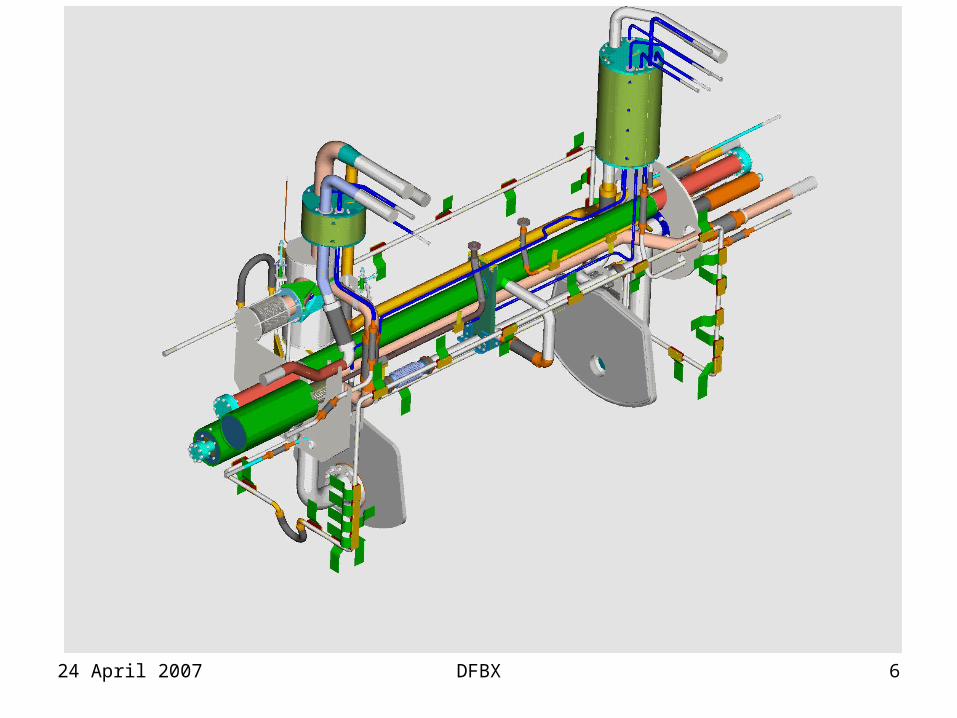
• DFBX designed at LBNL and fabricated at Meyer Tool near Chicago Illinois
• Fabrication oversight performed by Fermilab• Present team consists of
– Joseph Rasson (LBL), project manager – Steve Virostek (LBL), engineer – Frederic Gicquel (LBL @ CERN), engineer – Tom Peterson (Fermilab), engineer – Phil Pfund (Fermilab), engineer
24 April 2007 DFBX 4
24 April 2007 DFBX 5
24 April 2007 DFBX 6
24 April 2007 DFBX 7
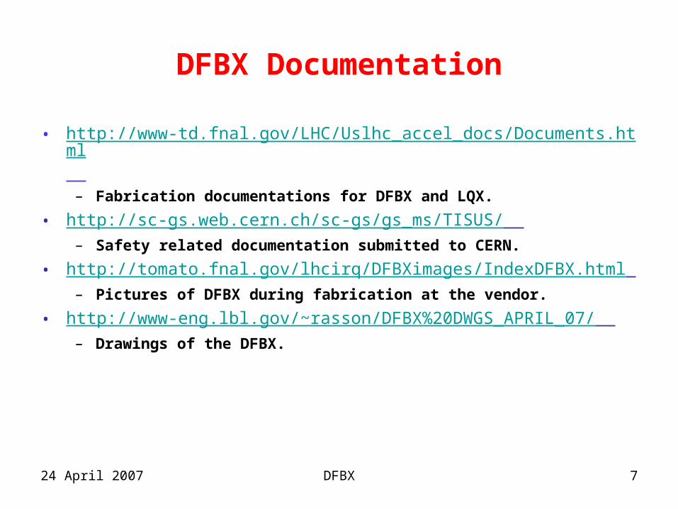
DFBX Documentation
• http://www-td.fnal.gov/LHC/Uslhc_accel_docs/Documents.html – Fabrication documentations for DFBX and LQX.
• http://sc-gs.web.cern.ch/sc-gs/gs_ms/TISUS/ – Safety related documentation submitted to CERN.
• http://tomato.fnal.gov/lhcirq/DFBXimages/IndexDFBX.html – Pictures of DFBX during fabrication at the vendor.
• http://www-eng.lbl.gov/~rasson/DFBX%20DWGS_APRIL_07/ – Drawings of the DFBX.
24 April 2007 DFBX 8
Flow schematic
• The inner triplet cryogenic flow schematic was developed in close collaboration between– Rob Van Weelderen (CERN)– Jon Zbasnik (LBL)– Tom Peterson (Fermilab).
• The following are excerpts from the DFBX G/C and DFBX E flow schemes.
24 April 2007 DFBX 9
Overview of DFBX Flow Schemes
• 8 DFBX’s, 6 different types – QRL on wall side, so left and right at each location
differ in being “left handed” and “right handed”– Points 2 and 8 have the same configuration with cold
D1, so DFBX C is identical to G and DFBX D is identical to H.
– Points 1 and 5 differ from 2 and 8 in having warm D1 and differ from each other in having opposite slopes.
24 April 2007 DFBX 10
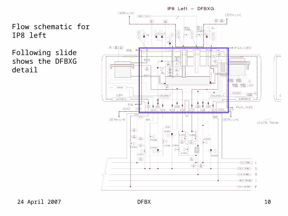
Flow schematic for IP8 left
Following slide shows the DFBXG detail
24 April 2007 DFBX 11
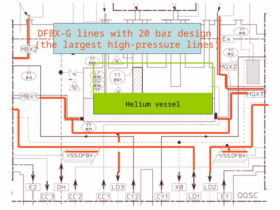
Helium vessel
DFBX-G lines with 20 bar design (the largest high-pressure lines)
24 April 2007 DFBX 12
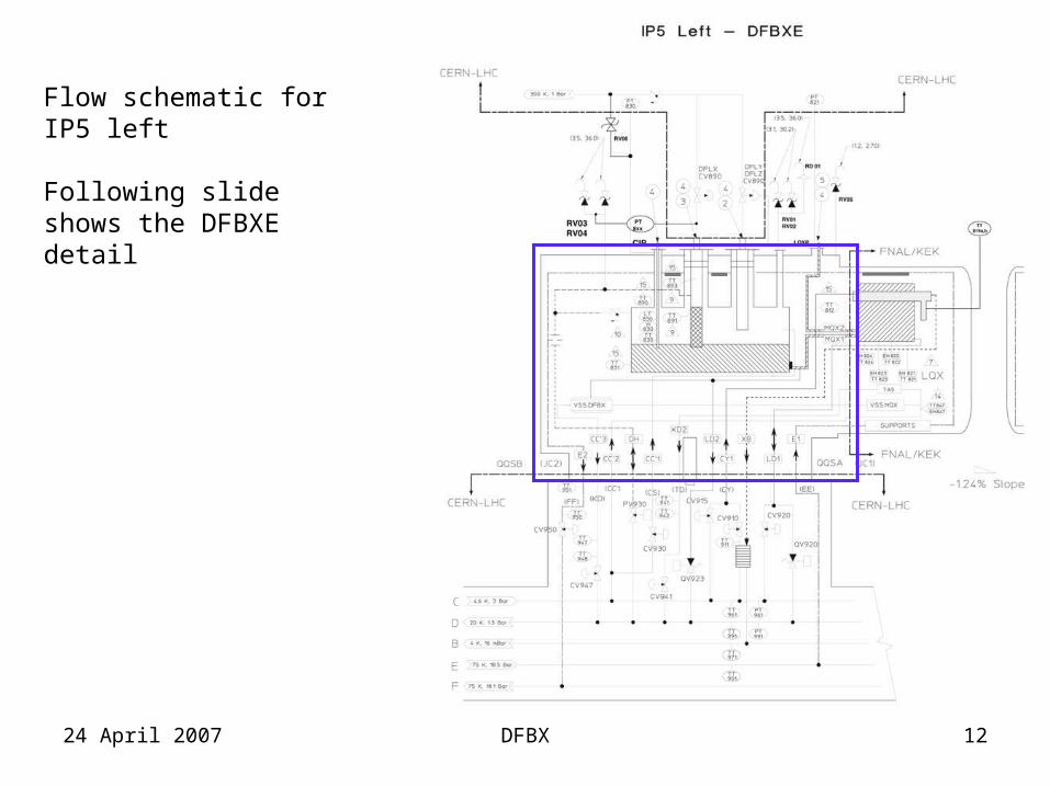
Flow schematic for IP5 left
Following slide shows the DFBXE detail
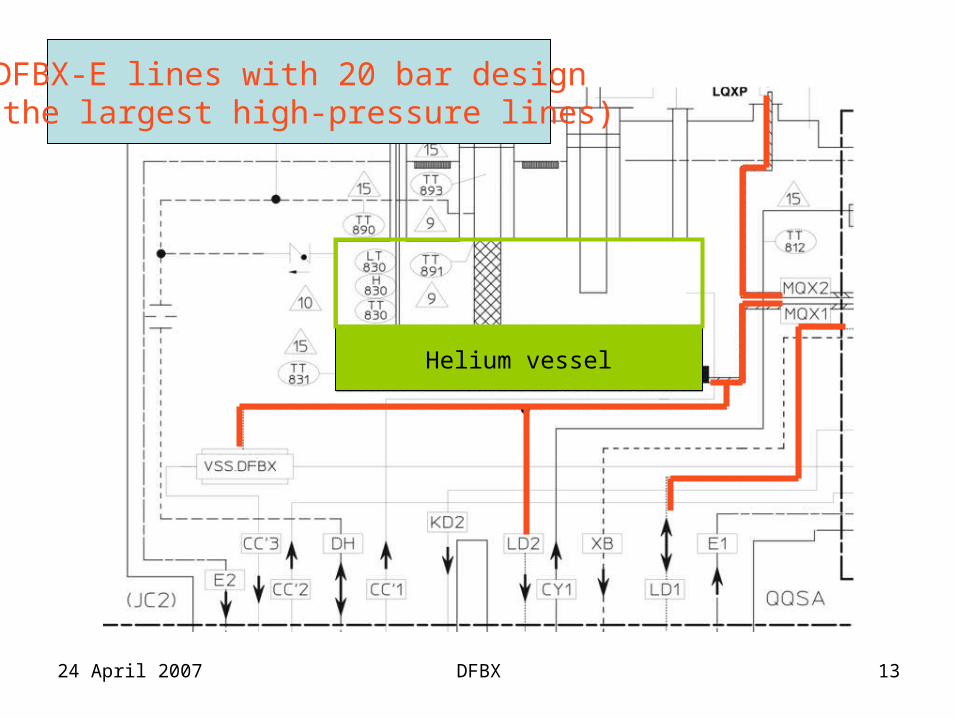
24 April 2007 DFBX 13
DFBX-E lines with 20 bar design (the largest high-pressure lines)
Helium vessel
24 April 2007 DFBX 14
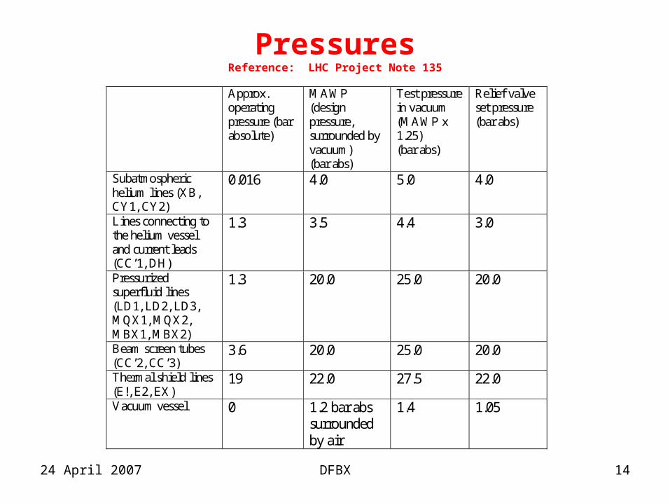
PressuresReference: LHC Project Note 135
Approx. operating pressure (bar absolute)
MAWP (design pressure, surrounded by vacuum) (bar abs)
Test pressure in vacuum (MAWP x 1.25) (bar abs)
Relief valve set pressure (bar abs)
Subatmospheric helium lines (XB, CY1, CY2)
0.016 4.0 5.0 4.0
Lines connecting to the helium vessel and current leads (CC’1, DH)
1.3 3.5 4.4 3.0
Pressurized superfluid lines (LD1, LD2, LD3, MQX1, MQX2, MBX1, MBX2)
1.3 20.0 25.0 20.0
Beam screen tubes (CC’2, CC’3)
3.6 20.0 25.0 20.0
Thermal shield lines (E!, E2, EX)
19 22.0 27.5 22.0
Vacuum vessel 0 1.2 bar abs surrounded by air
1.4 1.05
24 April 2007 DFBX 15
Mechanical Test Protocol
Tests at the manufacturer (Doc. M989A):• Cold shock all welds at least one cycle• Cold shock chimney bellows 25 cycles• Pressure test all components at set test pressure• Vacuum leak check all components• Final system pressure test and vacuum leak check• Measurements of all critical dimensions
Vacuum leak checks and measurement of critical dimensions were repeated at CERN after shipping:
See Doc LHC-DFBX-001-10-00
24 April 2007 DFBX 16
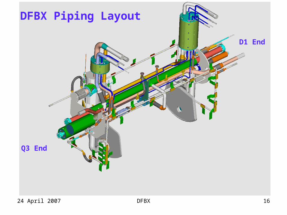
Q3 End
D1 End
DFBX Piping Layout
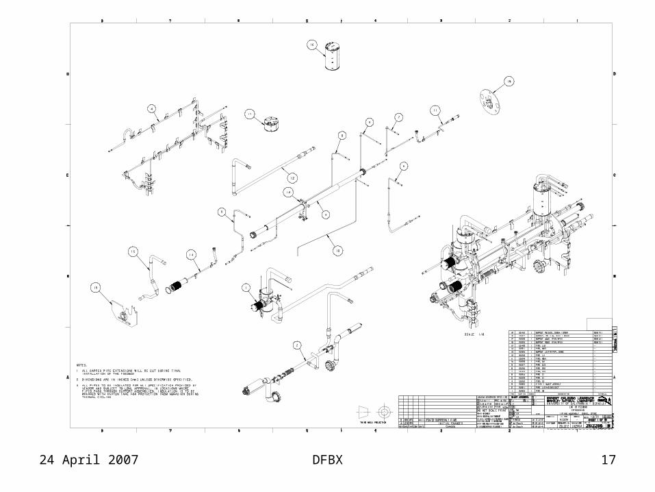
24 April 2007 DFBX 17
24 April 2007 DFBX 18
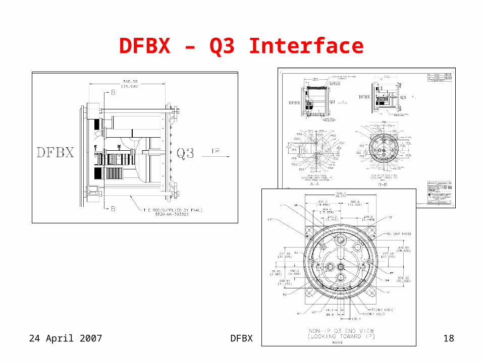
DFBX – Q3 Interface
24 April 2007 DFBX 19
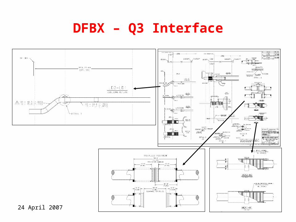
DFBX – Q3 Interface
24 April 2007 DFBX 20
Mechanical Loads
• Mechanical loads on the DFBX are Generated from:– Thermal contraction of spool pieces and magnets– Thrust load from bellows (positive and vacuum
pressures)– Internal pressure (positive and vacuum pressures)– Gravitational loads (weight)
24 April 2007 DFBX 21
Forces from Thermal Contractions
• Dominated by contraction of magnet ends away from DFBX – Q3 lines pull back 16.3 mm – D1 lines pull back ~20mm D1 fixed support at Center
• Internal DFBX components: Max thermal contractions is ~ 6 mm
• Design Approach:Neutralize mechanical forces generated from thermal contraction with the use of flex hoses
24 April 2007 DFBX 22
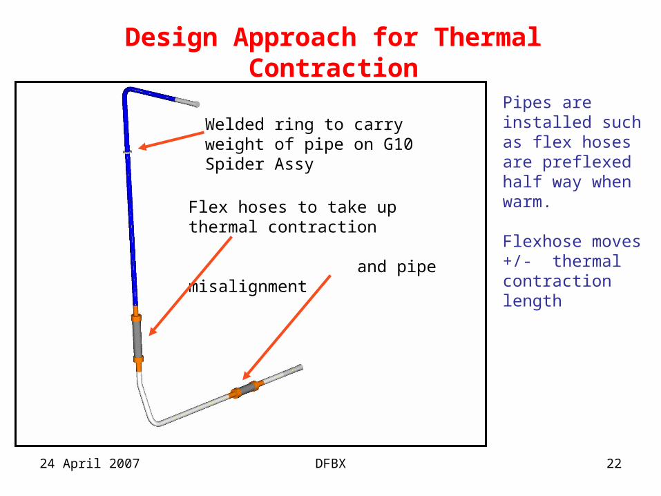
Design Approach for Thermal Contraction
Flex hoses to take up thermal contraction
and pipe misalignment
Pipes are installed such as flex hoses are preflexed half way when warm.
Flexhose moves +/- thermal contraction length
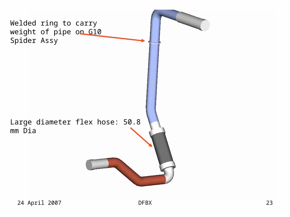
Welded ring to carry weight of pipe on G10 Spider Assy
24 April 2007 DFBX 23
Large diameter flex hose: 50.8 mm Dia
Welded ring to carry weight of pipe on G10 Spider Assy
24 April 2007 DFBX 24
Gravitational Loads
• Weight of most spool pieces is supported on G10 spiders in jumpers
• Spiders also provide mean to keep the pipes aligned during and after interconnection
• Weight of LHe vessel and bus ducts is transferred to vacuum vessel via 4- 19 mm invar rods (to be discussed later)
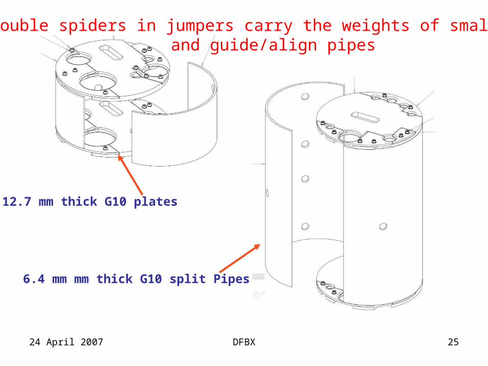
24 April 2007 DFBX 25
Double spiders in jumpers carry the weights of small pipesand guide/align pipes
6.4 mm mm thick G10 split Pipes
12.7 mm thick G10 plates

24 April 2007 DFBX 26
22.2 mm thick G10 plate
12.7 mm thick G10 plates
Non Load Bearing G10 Support SpidersD1 End
Bus duct SS support clampsand split rings
Beam pipeCenter support
Attached toLHe vessel
Q3 End
24 April 2007 DFBX 27
Thrust Loads in DFBX
• Limited to components with bellows at the ends for ease of interconnect and to allow for thermal contraction:
• XB: Q3-DFBX pumping line• MQX1: Q3-DFBX bus duct• MBX1: D1-DFBX bus duct• LD cross-over line inside the box whenever we
have cold D1 (4 boxes)
24 April 2007 DFBX 28
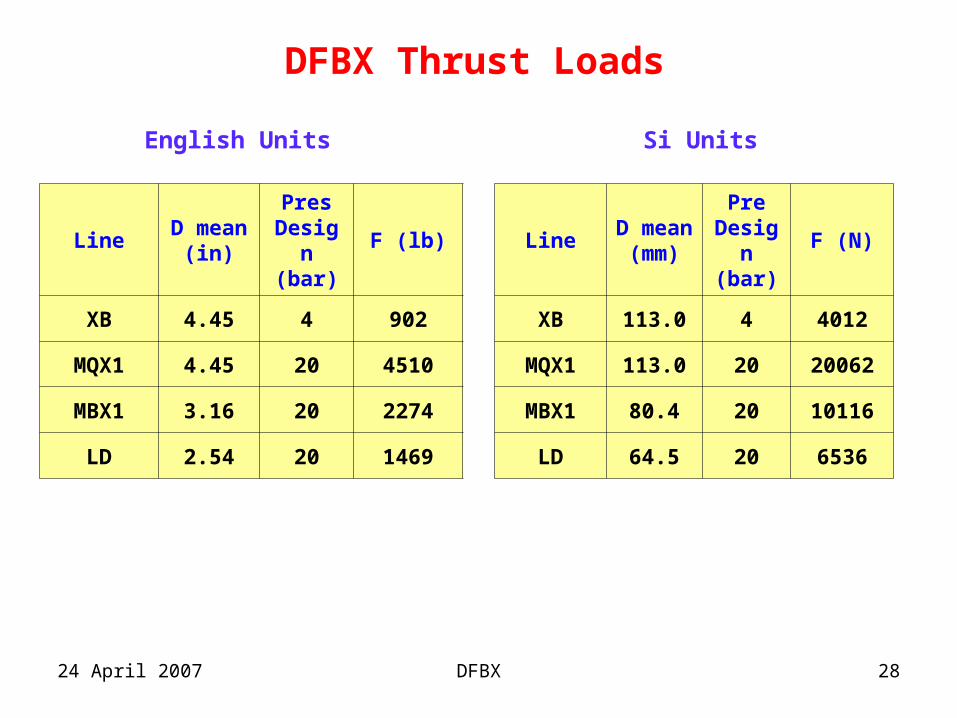
DFBX Thrust Loads
Si UnitsEnglish Units
LineD mean
(in)
Pres Design (bar)
F (lb)
XB 4.45 4 902
MQX1 4.45 20 4510
MBX1 3.16 20 2274
LD 2.54 20 1469
LineD mean (mm)
PreDesign(bar)
F (N)
XB 113.0 4 4012
MQX1 113.0 20 20062
MBX1 80.4 20 10116
LD 64.5 20 6536
24 April 2007 DFBX 29
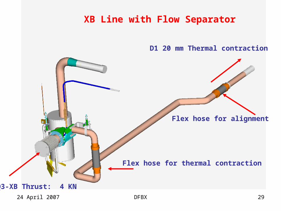
Q3-XB Thrust: 4 KN
D1 20 mm Thermal contraction
XB Line with Flow Separator
Flex hose for thermal contraction
Flex hose for alignment
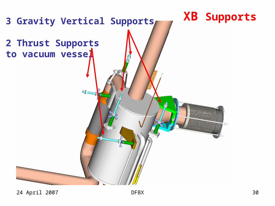
24 April 2007 DFBX 30
3 Gravity Vertical Supports
2 Thrust Supportsto vacuum vessel
XB Supports
24 April 2007 DFBX 31
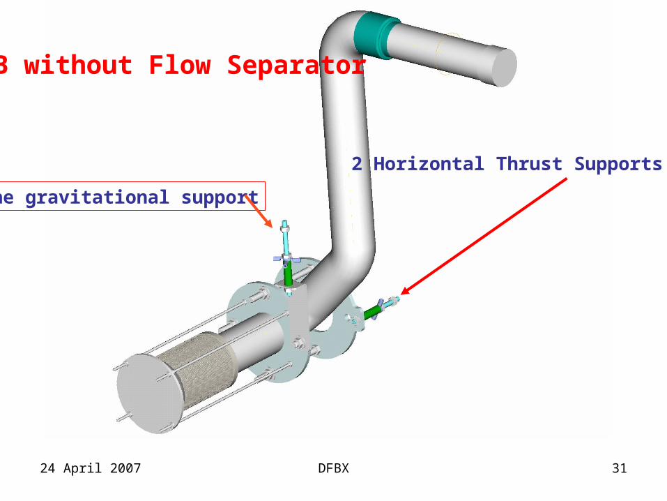
XB without Flow Separator
2 Horizontal Thrust Supports
One gravitational support
24 April 2007 DFBX 32
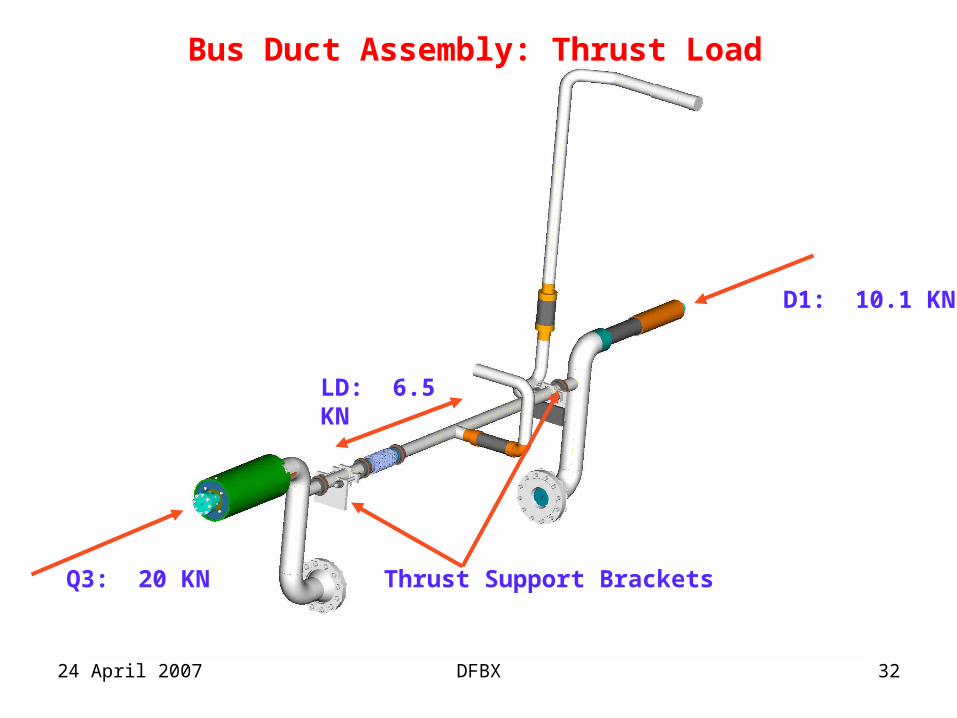
Q3: 20 KN
LD: 6.5 KN
D1: 10.1 KN
Bus Duct Assembly: Thrust Load
Thrust Support Brackets
24 April 2007 DFBX 33
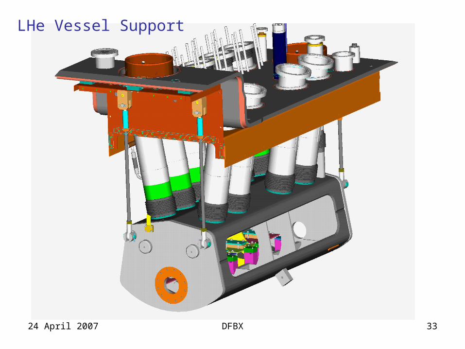
LHe Vessel Support
24 April 2007 DFBX 34
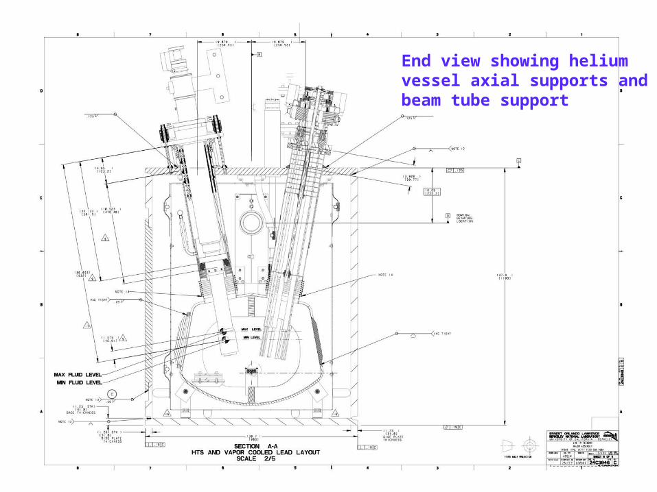
End view showing helium vessel axial supports and beam tube support
24 April 2007 DFBX 35
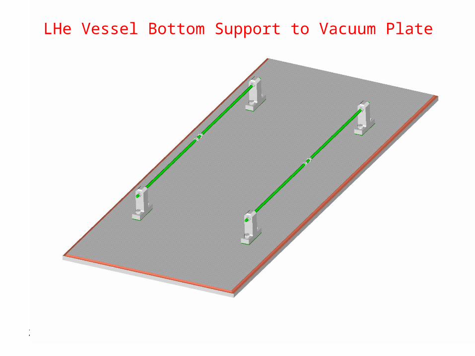
LHe Vessel Bottom Support to Vacuum Plate
24 April 2007 DFBX 36
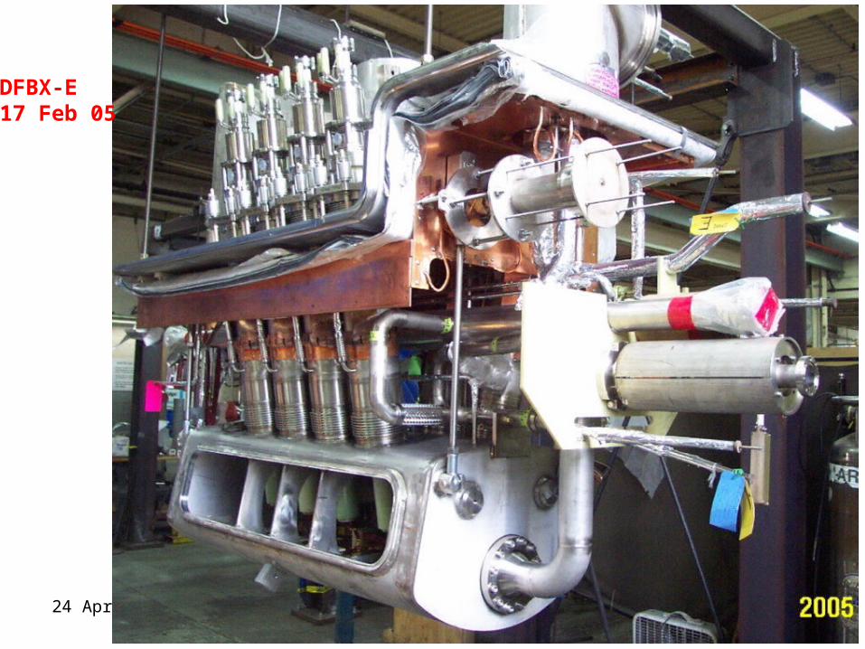
DFBX-E 17 Feb 05
24 April 2007 DFBX 37
Free Body Diagrams
• General diagrams showing approximate magnitude of force
• More detailed analysis will be presented at the component level
24 April 2007 DFBX 38
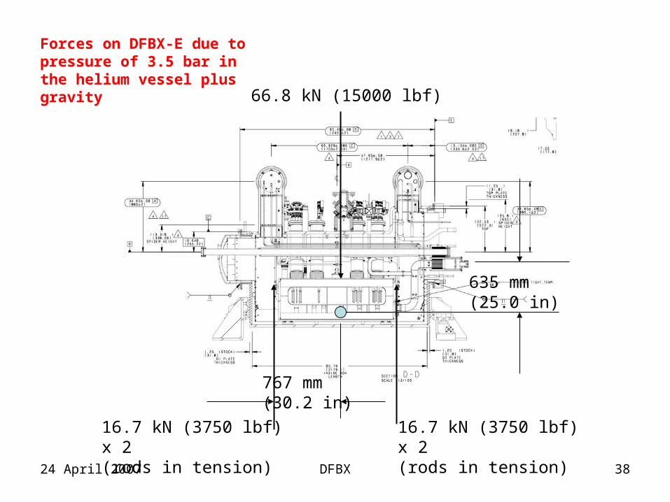
635 mm (25.0 in)
767 mm (30.2 in)
16.7 kN (3750 lbf) x 2 (rods in tension)
Forces on DFBX-E due to pressure of 3.5 bar in the helium vessel plus gravity 66.8 kN (15000 lbf)
16.7 kN (3750 lbf) x 2 (rods in tension)
24 April 2007 DFBX 39
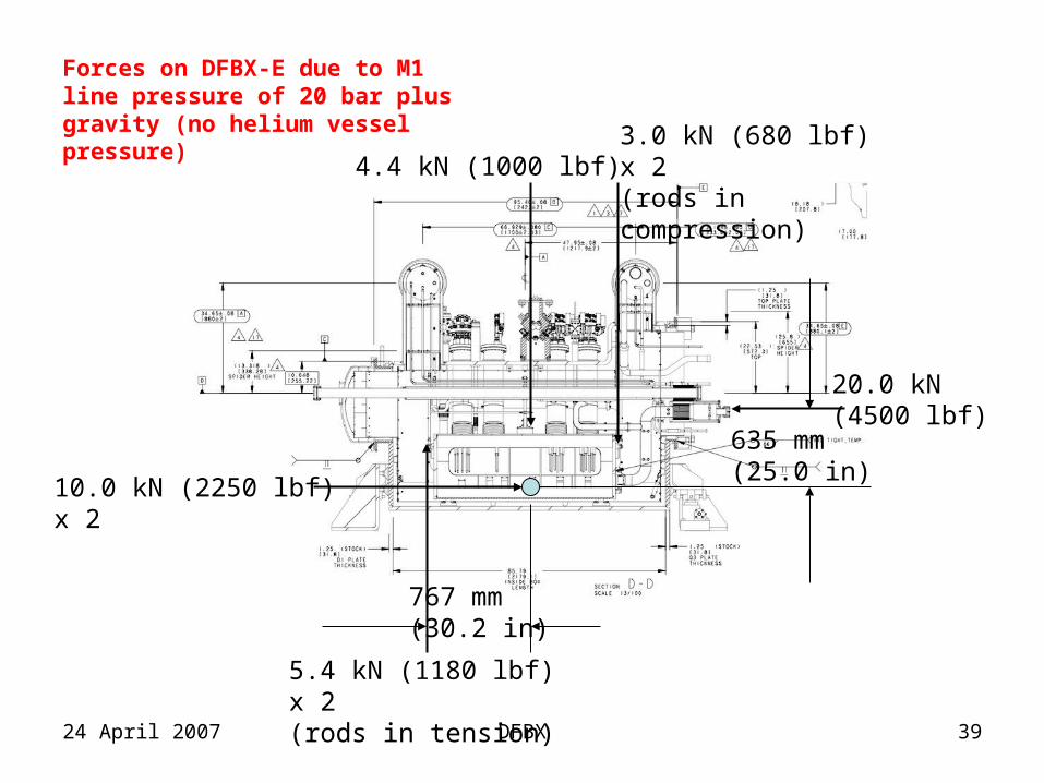
20.0 kN (4500 lbf)
10.0 kN (2250 lbf) x 2
635 mm (25.0 in)
767 mm (30.2 in)
5.4 kN (1180 lbf) x 2 (rods in tension)
3.0 kN (680 lbf) x 2 (rods in compression)
Forces on DFBX-E due to M1 line pressure of 20 bar plus gravity (no helium vessel pressure)
4.4 kN (1000 lbf)
24 April 2007 DFBX 40
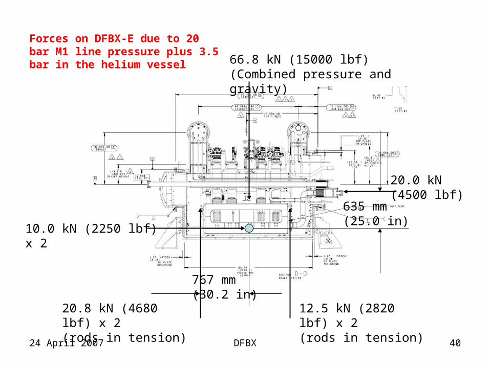
20.0 kN (4500 lbf)
10.0 kN (2250 lbf) x 2
635 mm (25.0 in)
767 mm (30.2 in)
12.5 kN (2820 lbf) x 2 (rods in tension)
66.8 kN (15000 lbf) (Combined pressure and gravity)
Forces on DFBX-E due to 20 bar M1 line pressure plus 3.5 bar in the helium vessel
20.8 kN (4680 lbf) x 2 (rods in tension)
24 April 2007 DFBX 41
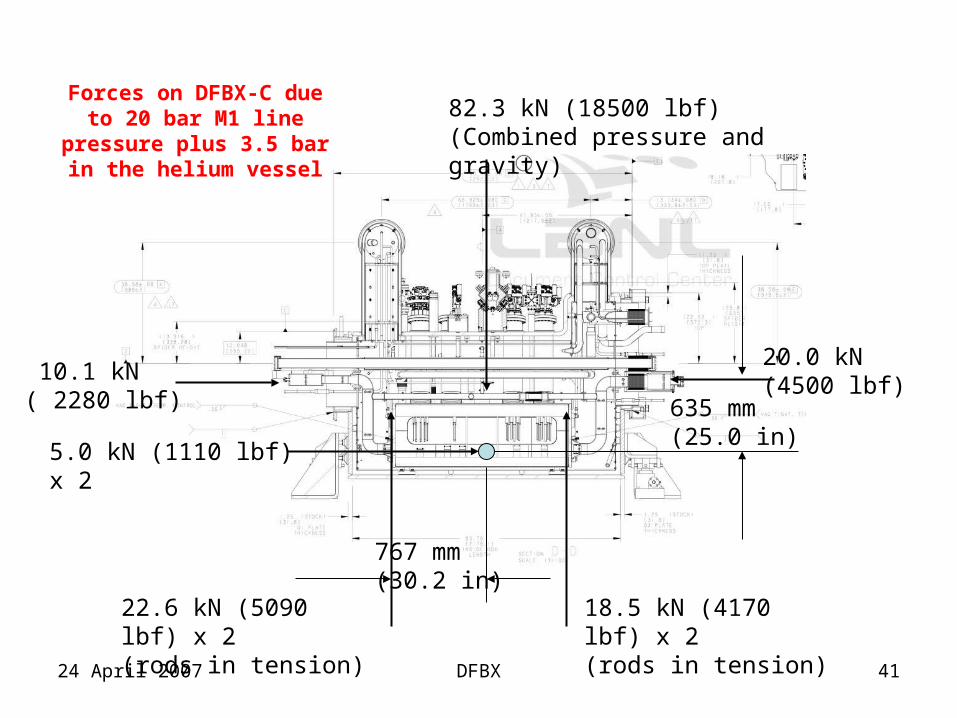
Forces on DFBX-C due to 20 bar M1 line pressure
plus 3.5 bar in the helium vessel
20.0 kN (4500 lbf)
5.0 kN (1110 lbf) x 2
635 mm (25.0 in)
767 mm (30.2 in)
18.5 kN (4170 lbf) x 2 (rods in tension)
22.6 kN (5090 lbf) x 2 (rods in tension)
10.1 kN ( 2280 lbf)
82.3 kN (18500 lbf) (Combined pressure and gravity)
24 April 2007 DFBX 42
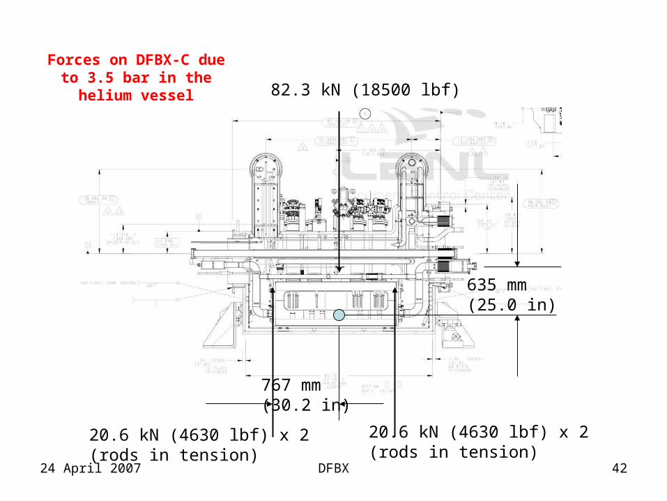
635 mm (25.0 in)
767 mm (30.2 in)
Forces on DFBX-C due to 3.5 bar in the helium vessel 82.3 kN (18500 lbf)
20.6 kN (4630 lbf) x 2 (rods in tension)
20.6 kN (4630 lbf) x 2 (rods in tension)
DFBX Detailed Analysis
•Analysis assumptions and methodology
•He vessel supports - stress analysis
•Upper, vertical support rods and attachments•Lower, axial supports and attachments•He vessel cover plate weld – stress analysis
•Bus duct & thrust support – stress analysis
•XB line – load and stress analysis
•Vacuum Vessel Bumpers
Analysis Assumptions and Methodology
•Analyses assume worst case operating loads•3.5 bar absolute in helium vessel•20.1 kN (4510 lb) bus duct thrust load (20 bar)
•XB line thrust•4.0 kN (902 lb) thrust load (4 bar)•Possible added load from D1 line
•All components are assessed based on the material and weld allowable limits set forth by the ASME Pressure Vessel Code•Code limits are for guidance and not a hard requirement
Helium Vessel Support Loads
•Reaction loads are based on the results of the helium vessel FEA model runs
•A portion of the bus duct thrust load is reacted at the stack bellows due to their high lateral stiffness
•Vertical strut loads are affected by the moment from bus duct thrust load
•The worst case vertical support rod and axial support loads are used for all analyses•Peak axial support load: 8.7 kN (1962 lb)•Peak strut tensile load (Q3 side): 15.9 kN (3570 lb)•Peak strut tensile load (D1 side): 19.6 kN (4414 lb)•Peak strut compressive load: 3.03 kN (682 lb)
Pressure Vessel Code Stress Limits
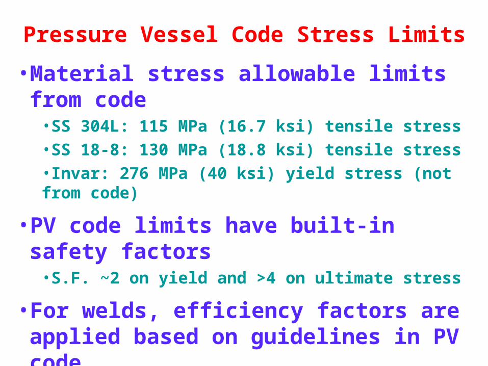
•Material stress allowable limits from code•SS 304L: 115 MPa (16.7 ksi) tensile stress•SS 18-8: 130 MPa (18.8 ksi) tensile stress•Invar: 276 MPa (40 ksi) yield stress (not from code)
•PV code limits have built-in safety factors•S.F. ~2 on yield and >4 on ultimate stress
•For welds, efficiency factors are applied based on guidelines in PV code
•Tensile and shear stresses are combined using von Mises formulation
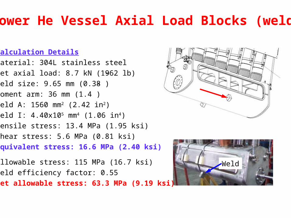
Lower He Vessel Axial Load Blocks (weld)
Calculation Details
Material: 304L stainless steel
Net axial load: 8.7 kN (1962 lb)
Weld size: 9.65 mm (0.38”)
Moment arm: 36 mm (1.4”)
Weld A: 1560 mm2 (2.42 in2)
Weld I: 4.40x105 mm4 (1.06 in4)
Tensile stress: 13.4 MPa (1.95 ksi)
Shear stress: 5.6 MPa (0.81 ksi)
Equivalent stress: 16.6 MPa (2.40 ksi)
Allowable stress: 115 MPa (16.7 ksi)
Weld efficiency factor: 0.55
Net allowable stress: 63.3 MPa (9.19 ksi)
Weld
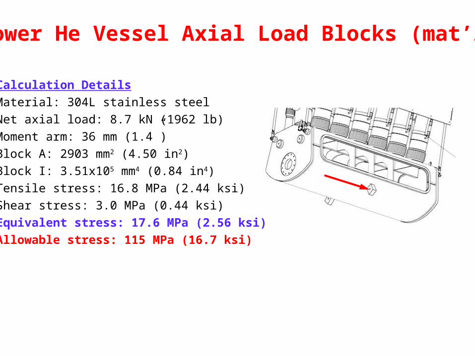
Lower He Vessel Axial Load Blocks (mat’l)
Calculation Details
Material: 304L stainless steel
Net axial load: 8.7 kN (1962 lb)
Moment arm: 36 mm (1.4”)
Block A: 2903 mm2 (4.50 in2)
Block I: 3.51x105 mm4 (0.84 in4)
Tensile stress: 16.8 MPa (2.44 ksi)
Shear stress: 3.0 MPa (0.44 ksi)
Equivalent stress: 17.6 MPa (2.56 ksi)
Allowable stress: 115 MPa (16.7 ksi)
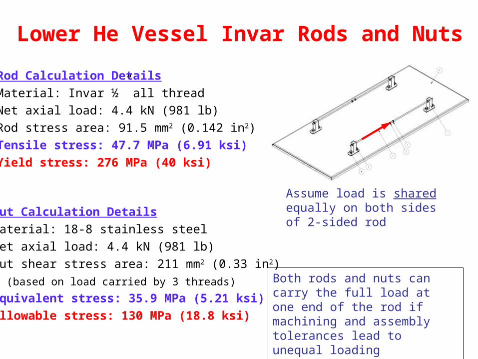
Lower He Vessel Invar Rods and Nuts
Rod Calculation Details
Material: Invar ½” all thread
Net axial load: 4.4 kN (981 lb)
Rod stress area: 91.5 mm2 (0.142 in2)
Tensile stress: 47.7 MPa (6.91 ksi)
Yield stress: 276 MPa (40 ksi)
Assume load is shared equally on both sides of 2-sided rodNut Calculation Details
Material: 18-8 stainless steel
Net axial load: 4.4 kN (981 lb)
Nut shear stress area: 211 mm2 (0.33 in2)
(based on load carried by 3 threads)
Equivalent stress: 35.9 MPa (5.21 ksi)
Allowable stress: 130 MPa (18.8 ksi)
Both rods and nuts can carry the full load at one end of the rod if machining and assembly tolerances lead to unequal loading
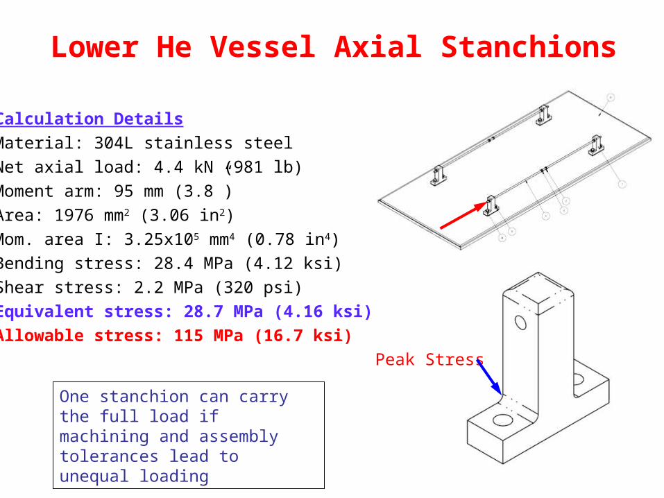
Lower He Vessel Axial Stanchions
Calculation Details
Material: 304L stainless steel
Net axial load: 4.4 kN (981 lb)
Moment arm: 95 mm (3.8”)
Area: 1976 mm2 (3.06 in2)
Mom. area I: 3.25x105 mm4 (0.78 in4)
Bending stress: 28.4 MPa (4.12 ksi)
Shear stress: 2.2 MPa (320 psi)
Equivalent stress: 28.7 MPa (4.16 ksi)
Allowable stress: 115 MPa (16.7 ksi)
One stanchion can carry the full load if machining and assembly tolerances lead to unequal loading
Peak Stress
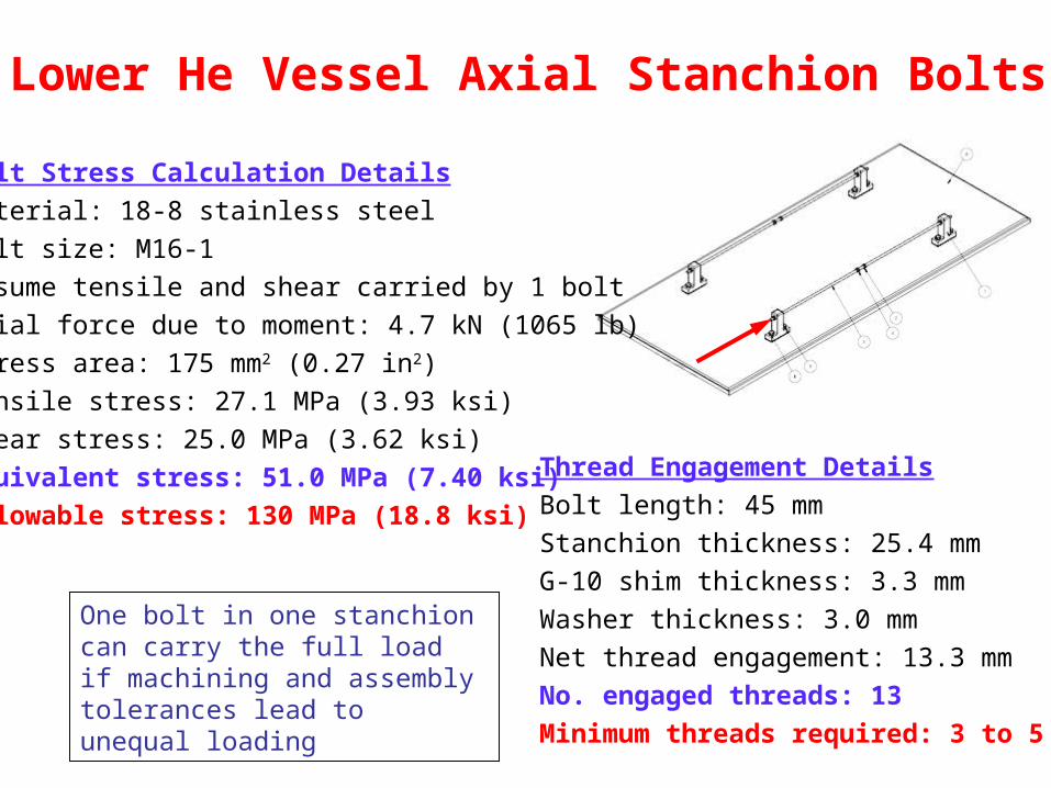
Lower He Vessel Axial Stanchion Bolts
Bolt Stress Calculation Details
Material: 18-8 stainless steel
Bolt size: M16-1
Assume tensile and shear carried by 1 bolt
Axial force due to moment: 4.7 kN (1065 lb)
Stress area: 175 mm2 (0.27 in2)
Tensile stress: 27.1 MPa (3.93 ksi)
Shear stress: 25.0 MPa (3.62 ksi)
Equivalent stress: 51.0 MPa (7.40 ksi)
Allowable stress: 130 MPa (18.8 ksi)
Thread Engagement Details
Bolt length: 45 mm
Stanchion thickness: 25.4 mm
G-10 shim thickness: 3.3 mm
Washer thickness: 3.0 mm
Net thread engagement: 13.3 mm
No. engaged threads: 13
Minimum threads required: 3 to 5
One bolt in one stanchion can carry the full load if machining and assembly tolerances lead to unequal loading
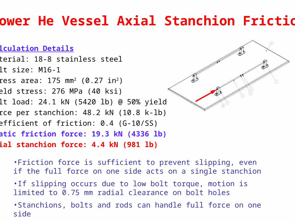
Lower He Vessel Axial Stanchion Friction
Calculation Details
Material: 18-8 stainless steel
Bolt size: M16-1
Stress area: 175 mm2 (0.27 in2)
Yield stress: 276 MPa (40 ksi)
Bolt load: 24.1 kN (5420 lb) @ 50% yield
Force per stanchion: 48.2 kN (10.8 k-lb)
Coefficient of friction: 0.4 (G-10/SS)
Static friction force: 19.3 kN (4336 lb)
Axial stanchion force: 4.4 kN (981 lb)
•Friction force is sufficient to prevent slipping, even if the full force on one side acts on a single stanchion
•If slipping occurs due to low bolt torque, motion is limited to 0.75 mm radial clearance on bolt holes
•Stanchions, bolts and rods can handle full force on one side
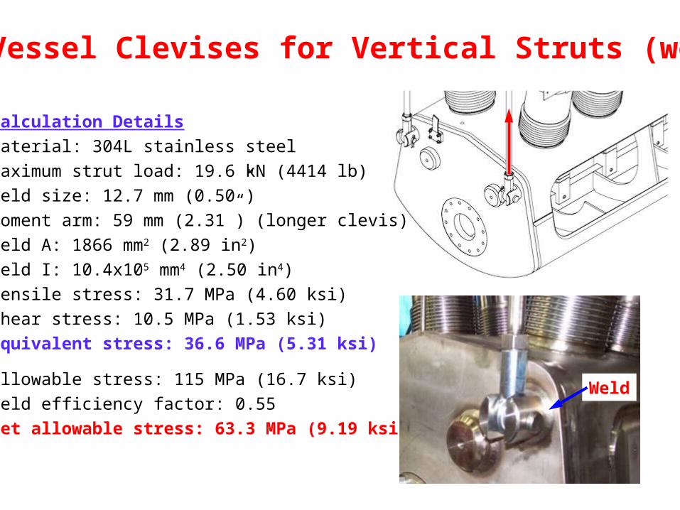
He Vessel Clevises for Vertical Struts (weld)
Calculation Details
Material: 304L stainless steel
Maximum strut load: 19.6 kN (4414 lb)
Weld size: 12.7 mm (0.50”)
Moment arm: 59 mm (2.31”) (longer clevis)
Weld A: 1866 mm2 (2.89 in2)
Weld I: 10.4x105 mm4 (2.50 in4)
Tensile stress: 31.7 MPa (4.60 ksi)
Shear stress: 10.5 MPa (1.53 ksi)
Equivalent stress: 36.6 MPa (5.31 ksi)
Allowable stress: 115 MPa (16.7 ksi)
Weld efficiency factor: 0.55
Net allowable stress: 63.3 MPa (9.19 ksi)
Weld
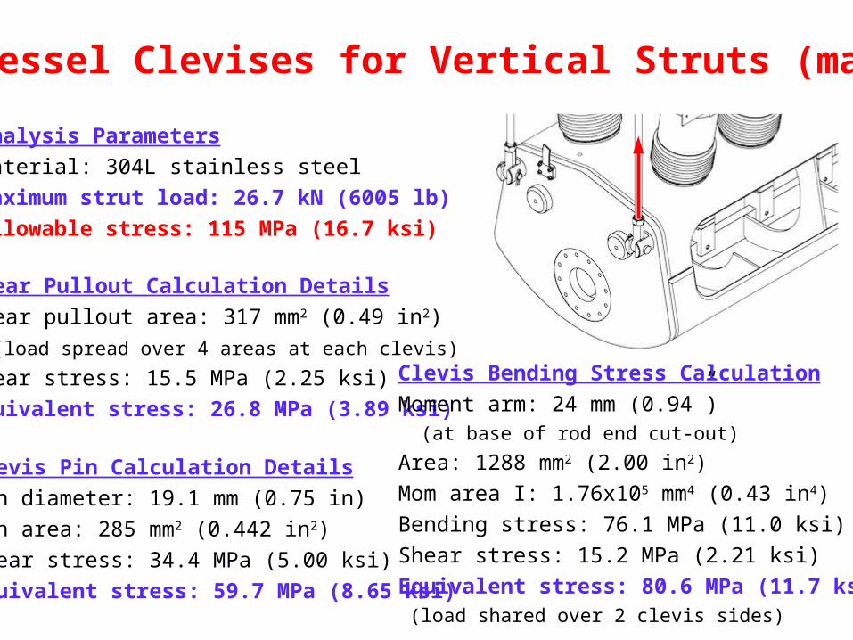
He Vessel Clevises for Vertical Struts (mat’l)
Analysis Parameters
Material: 304L stainless steel
Maximum strut load: 26.7 kN (6005 lb)
Allowable stress: 115 MPa (16.7 ksi)
Shear Pullout Calculation Details
Shear pullout area: 317 mm2 (0.49 in2)
(load spread over 4 areas at each clevis)
Shear stress: 15.5 MPa (2.25 ksi)
Equivalent stress: 26.8 MPa (3.89 ksi)
Clevis Bending Stress Calculation
Moment arm: 24 mm (0.94”) (at base of rod end cut-out)
Area: 1288 mm2 (2.00 in2)
Mom area I: 1.76x105 mm4 (0.43 in4)
Bending stress: 76.1 MPa (11.0 ksi)
Shear stress: 15.2 MPa (2.21 ksi)
Equivalent stress: 80.6 MPa (11.7 ksi) (load shared over 2 clevis sides)
Clevis Pin Calculation Details
Pin diameter: 19.1 mm (0.75 in)
Pin area: 285 mm2 (0.442 in2)
Shear stress: 34.4 MPa (5.00 ksi)
Equivalent stress: 59.7 MPa (8.65 ksi)
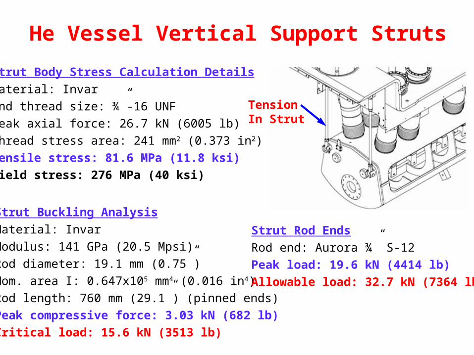
He Vessel Vertical Support Struts
TensionIn Strut
Strut Body Stress Calculation Details
Material: Invar
End thread size: ¾”-16 UNF
Peak axial force: 26.7 kN (6005 lb)
Thread stress area: 241 mm2 (0.373 in2)
Tensile stress: 81.6 MPa (11.8 ksi)
Yield stress: 276 MPa (40 ksi)
Strut Buckling Analysis
Material: Invar
Modulus: 141 GPa (20.5 Mpsi)
Rod diameter: 19.1 mm (0.75”)
Mom. area I: 0.647x105 mm4 (0.016 in4)
Rod length: 760 mm (29.1”) (pinned ends)
Peak compressive force: 3.03 kN (682 lb)
Critical load: 15.6 kN (3513 lb)
Strut Rod Ends
Rod end: Aurora ¾” S-12
Peak load: 19.6 kN (4414 lb)
Allowable load: 32.7 kN (7364 lb)
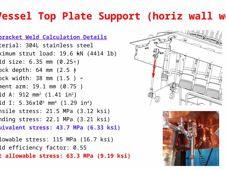
He Vessel Top Plate Support (horiz wall weld)
L-bracket Weld Calculation Details
Material: 304L stainless steel
Maximum strut load: 19.6 kN (4414 lb)
Weld size: 6.35 mm (0.25”)
Block depth: 64 mm (2.5”)
Block width: 38 mm (1.5”)
Moment arm: 19.1 mm (0.75”)
Weld A: 912 mm2 (1.41 in2)
Weld I: 5.36x105 mm4 (1.29 in4)
Tensile stress: 21.5 MPa (3.12 ksi)
Bending stress: 22.1 MPa (3.21 ksi)
Equivalent stress: 43.7 MPa (6.33 ksi)
Allowable stress: 115 MPa (16.7 ksi)
Weld efficiency factor: 0.55
Net allowable stress: 63.3 MPa (9.19 ksi)
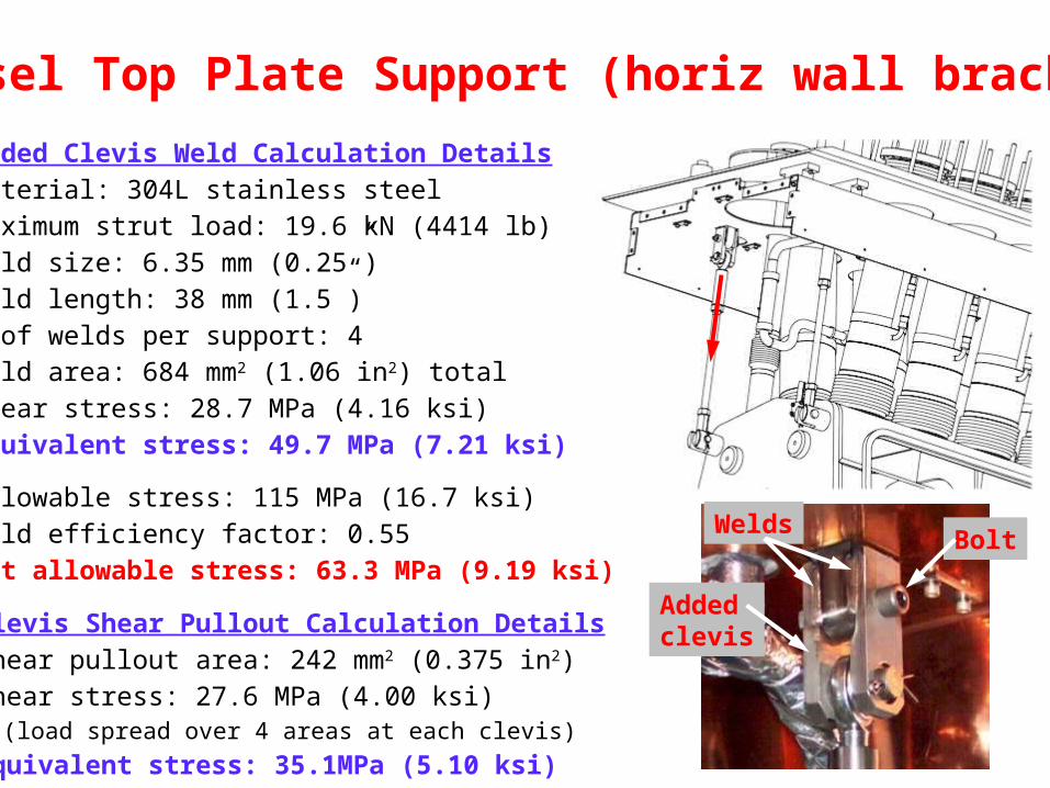
Vessel Top Plate Support (horiz wall bracket)
Added Clevis Weld Calculation DetailsMaterial: 304L stainless steelMaximum strut load: 19.6 kN (4414 lb) Weld size: 6.35 mm (0.25”)Weld length: 38 mm (1.5”)# of welds per support: 4Weld area: 684 mm2 (1.06 in2) totalShear stress: 28.7 MPa (4.16 ksi)Equivalent stress: 49.7 MPa (7.21 ksi)
Allowable stress: 115 MPa (16.7 ksi)Weld efficiency factor: 0.55Net allowable stress: 63.3 MPa (9.19 ksi)
Addedclevis
WeldsBolt
Clevis Shear Pullout Calculation DetailsShear pullout area: 242 mm2 (0.375 in2)Shear stress: 27.6 MPa (4.00 ksi) (load spread over 4 areas at each clevis)
Equivalent stress: 35.1MPa (5.10 ksi)
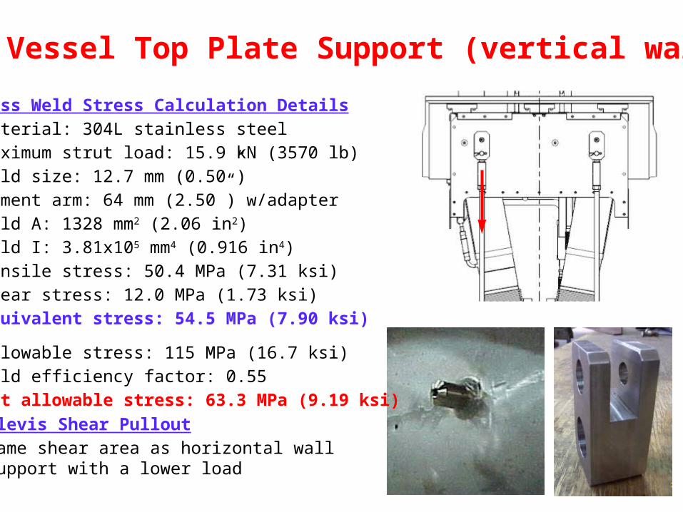
He Vessel Top Plate Support (vertical wall)
Boss Weld Stress Calculation DetailsMaterial: 304L stainless steelMaximum strut load: 15.9 kN (3570 lb) Weld size: 12.7 mm (0.50”)Moment arm: 64 mm (2.50”) w/adapterWeld A: 1328 mm2 (2.06 in2)Weld I: 3.81x105 mm4 (0.916 in4)Tensile stress: 50.4 MPa (7.31 ksi)Shear stress: 12.0 MPa (1.73 ksi)Equivalent stress: 54.5 MPa (7.90 ksi)
Allowable stress: 115 MPa (16.7 ksi)Weld efficiency factor: 0.55Net allowable stress: 63.3 MPa (9.19 ksi)
Clevis Shear PulloutSame shear area as horizontal wall support with a lower load
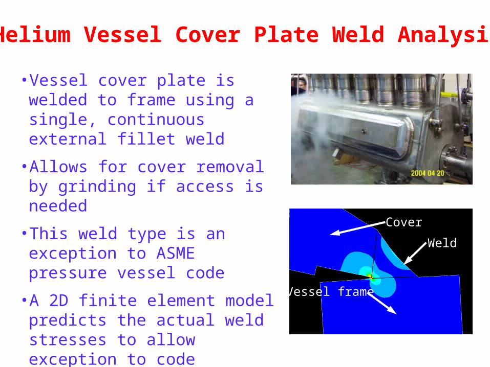
Helium Vessel Cover Plate Weld Analysis
• Vessel cover plate is welded to frame using a single, continuous external fillet weld
• Allows for cover removal by grinding if access is needed
• This weld type is an exception to ASME pressure vessel code
• A 2D finite element model predicts the actual weld stresses to allow exception to code
• Allowable stress is exceeded only in very small zone at the root of the weld (root stress < yield stress)
Vessel frame
Cover
Weld
24 April 2007 DFBX 60
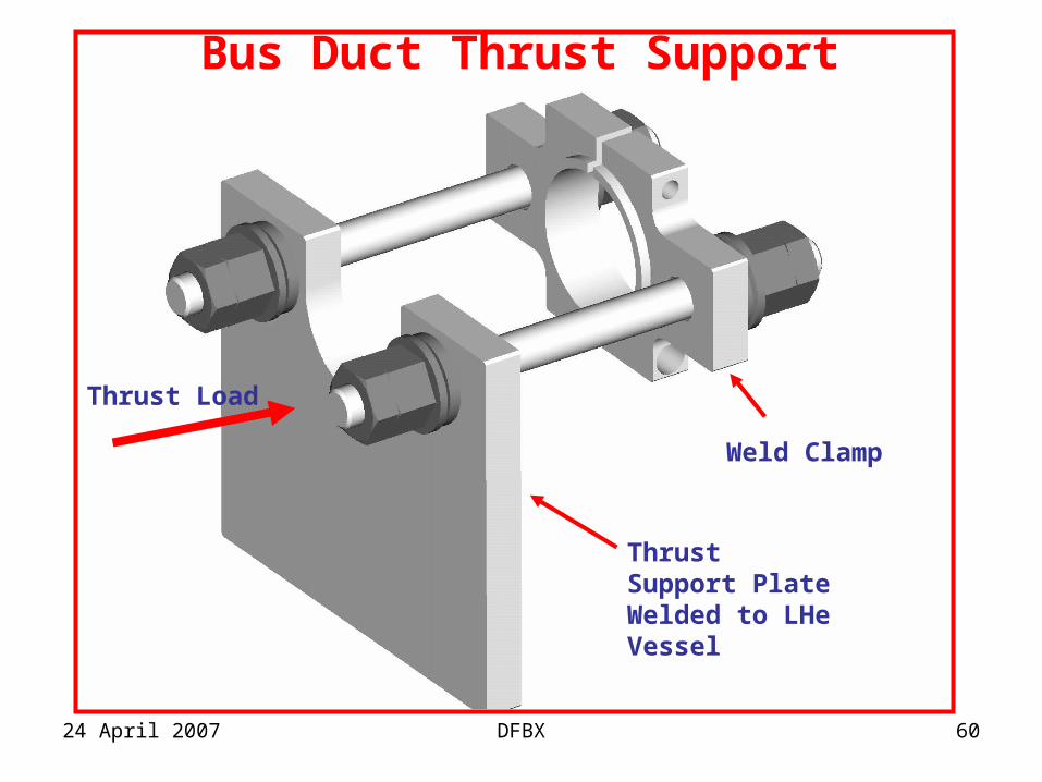
Bus Duct Thrust Support
Weld Clamp
Thrust Support Plate Welded to LHe Vessel
Thrust Load
24 April 2007 DFBX 61
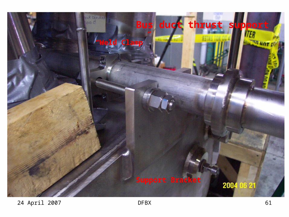
Bus duct thrust support
“Weld Clamp”
Support Bracket
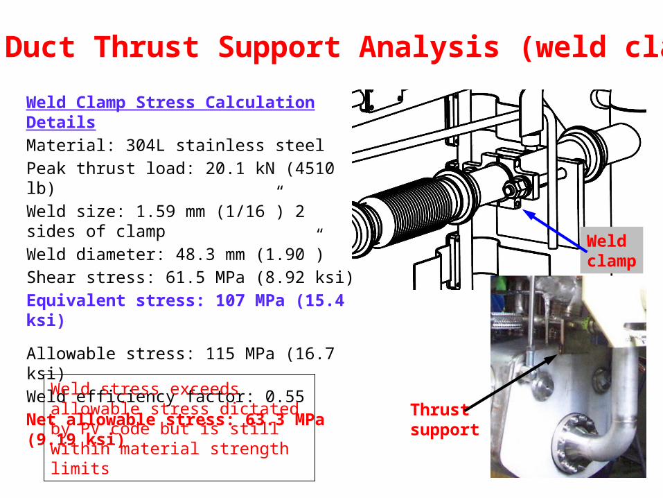
Bus Duct Thrust Support Analysis (weld clamp)
Weld Clamp Stress Calculation DetailsMaterial: 304L stainless steelPeak thrust load: 20.1 kN (4510 lb) Weld size: 1.59 mm (1/16”) 2 sides of clampWeld diameter: 48.3 mm (1.90”)Shear stress: 61.5 MPa (8.92 ksi)Equivalent stress: 107 MPa (15.4 ksi)
Allowable stress: 115 MPa (16.7 ksi)Weld efficiency factor: 0.55Net allowable stress: 63.3 MPa (9.19 ksi)
Weld stress exceeds allowable stress dictated by PV code but is still within material strength limits
Thrustsupport
Weldclamp
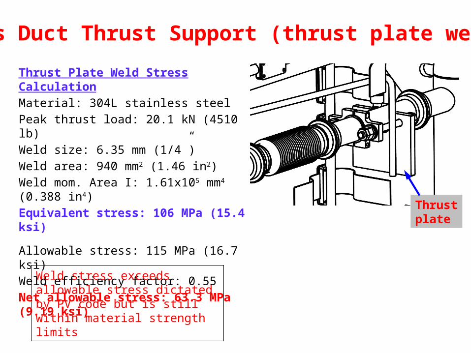
Bus Duct Thrust Support (thrust plate weld)
Thrust Plate Weld Stress CalculationMaterial: 304L stainless steelPeak thrust load: 20.1 kN (4510 lb) Weld size: 6.35 mm (1/4”)Weld area: 940 mm2 (1.46 in2)Weld mom. Area I: 1.61x105 mm4 (0.388 in4)Equivalent stress: 106 MPa (15.4 ksi)
Allowable stress: 115 MPa (16.7 ksi)Weld efficiency factor: 0.55Net allowable stress: 63.3 MPa (9.19 ksi)
Weld stress exceeds allowable stress dictated by PV code but is still within material strength limits
Thrustplate
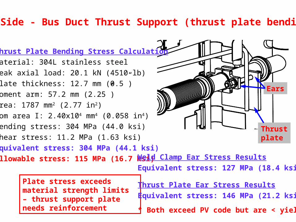
Q3 Side - Bus Duct Thrust Support (thrust plate bending)
Plate stress exceeds material strength limits – thrust support plate needs reinforcement
Thrustplate
Thrust Plate Bending Stress Calculation
Material: 304L stainless steel
Peak axial load: 20.1 kN (4510 lb)
Plate thickness: 12.7 mm (0.5”)
Moment arm: 57.2 mm (2.25”)
Area: 1787 mm2 (2.77 in2)
Mom area I: 2.40x104 mm4 (0.058 in4)
Bending stress: 304 MPa (44.0 ksi)
Shear stress: 11.2 MPa (1.63 ksi)
Equivalent stress: 304 MPa (44.1 ksi)
Allowable stress: 115 MPa (16.7 ksi) Weld Clamp Ear Stress Results
Equivalent stress: 127 MPa (18.4 ksi)*
Thrust Plate Ear Stress Results
Equivalent stress: 146 MPa (21.2 ksi)*
* Both exceed PV code but are < yield
Ears
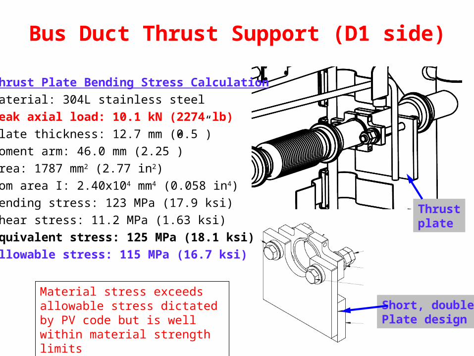
Bus Duct Thrust Support (D1 side)
Thrustplate
Thrust Plate Bending Stress Calculation
Material: 304L stainless steel
Peak axial load: 10.1 kN (2274 lb)
Plate thickness: 12.7 mm (0.5”)
Moment arm: 46.0 mm (2.25”)
Area: 1787 mm2 (2.77 in2)
Mom area I: 2.40x104 mm4 (0.058 in4)
Bending stress: 123 MPa (17.9 ksi)
Shear stress: 11.2 MPa (1.63 ksi)
Equivalent stress: 125 MPa (18.1 ksi)
Allowable stress: 115 MPa (16.7 ksi)
Material stress exceeds allowable stress dictated by PV code but is well within material strength limits
Short, doublePlate design
XB Line/Surge Tank Load Analysis
4.0 kN
4.0 kN.44 kN
3.4 kN
.80 kN3.4 kN
.65 kN1.0 kN
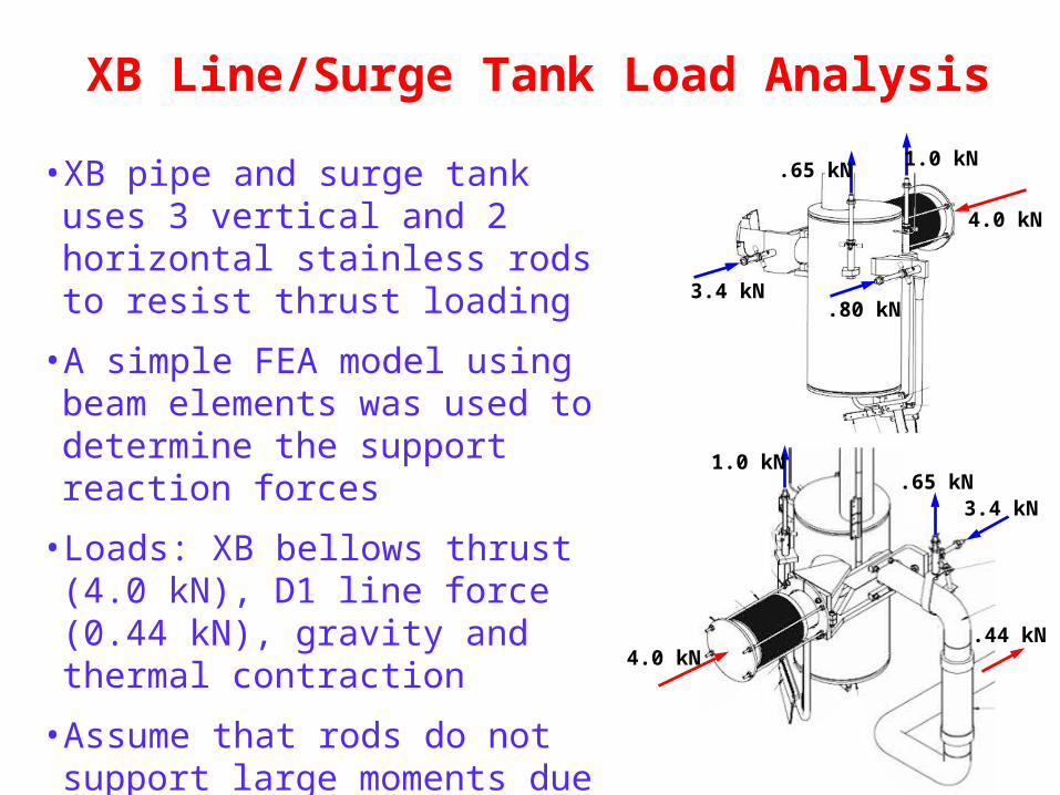
.65 kN1.0 kN• XB pipe and surge tank uses 3
vertical and 2 horizontal stainless rods to resist thrust loading
• A simple FEA model using beam elements was used to determine the support reaction forces
• Loads: XB bellows thrust (4.0 kN), D1 line force (0.44 kN), gravity and thermal contraction
• Assume that rods do not support large moments due to pivoting at ends and localized yielding (i.e. forces in rods are essentially axial)
XB Line/Surge Tank Stress Analysis
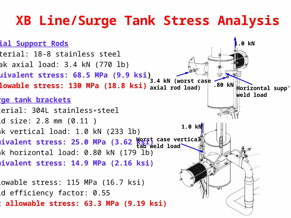
3.4 kN (worst caseaxial rod load)
1.0 kN
1.0 kN
Worst case verticaltab weld load
.80 kNHorizontal supp’tweld load
Axial Support Rods
Material: 18-8 stainless steel
Peak axial load: 3.4 kN (770 lb)
Equivalent stress: 68.5 MPa (9.9 ksi)
Allowable stress: 130 MPa (18.8 ksi)
Surge tank brackets
Material: 304L stainless steel
Weld size: 2.8 mm (0.11”)
Peak vertical load: 1.0 kN (233 lb)
Equivalent stress: 25.0 MPa (3.62 ksi)
Peak horizontal load: 0.80 kN (179 lb)
Equivalent stress: 14.9 MPa (2.16 ksi)
Allowable stress: 115 MPa (16.7 ksi)
Weld efficiency factor: 0.55
Net allowable stress: 63.3 MPa (9.19 ksi)
XB Line/Surge Tank Stress Analysis
3.4 kN
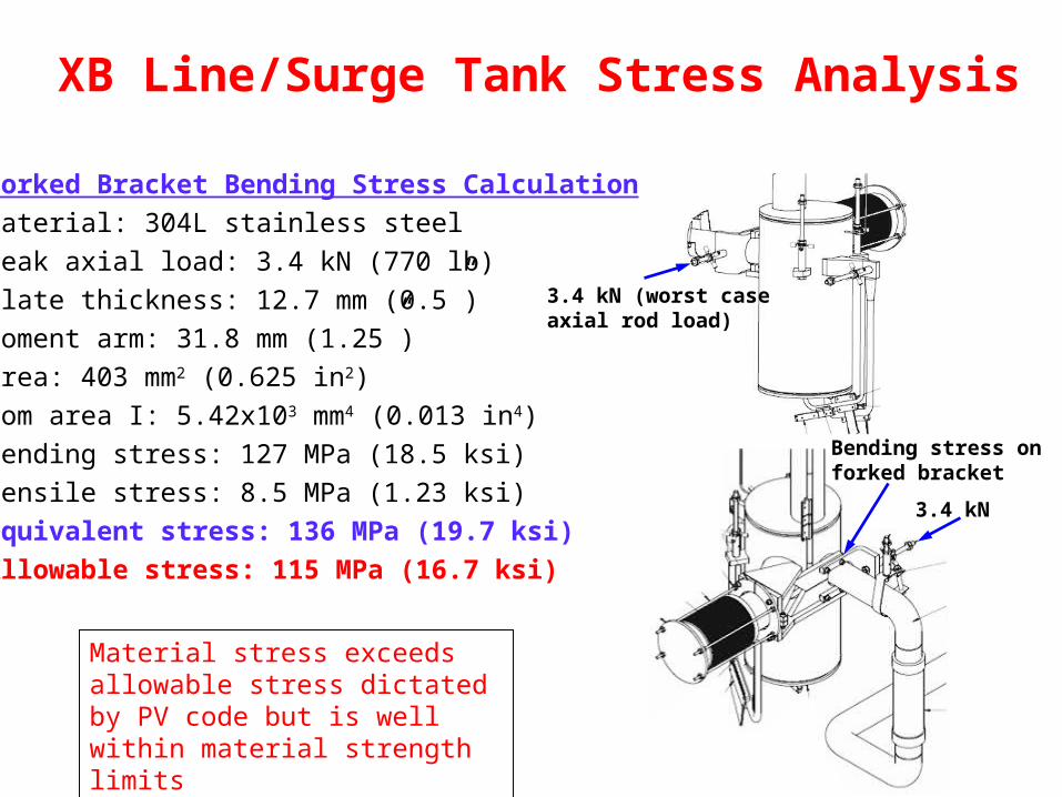
3.4 kN (worst caseaxial rod load)
Bending stress onforked bracket
Forked Bracket Bending Stress Calculation
Material: 304L stainless steel
Peak axial load: 3.4 kN (770 lb)
Plate thickness: 12.7 mm (0.5”)
Moment arm: 31.8 mm (1.25”)
Area: 403 mm2 (0.625 in2)
Mom area I: 5.42x103 mm4 (0.013 in4)
Bending stress: 127 MPa (18.5 ksi)
Tensile stress: 8.5 MPa (1.23 ksi)
Equivalent stress: 136 MPa (19.7 ksi)
Allowable stress: 115 MPa (16.7 ksi)
Material stress exceeds allowable stress dictated by PV code but is well within material strength limits
XB Line (w/o surge tank) Load Analysis
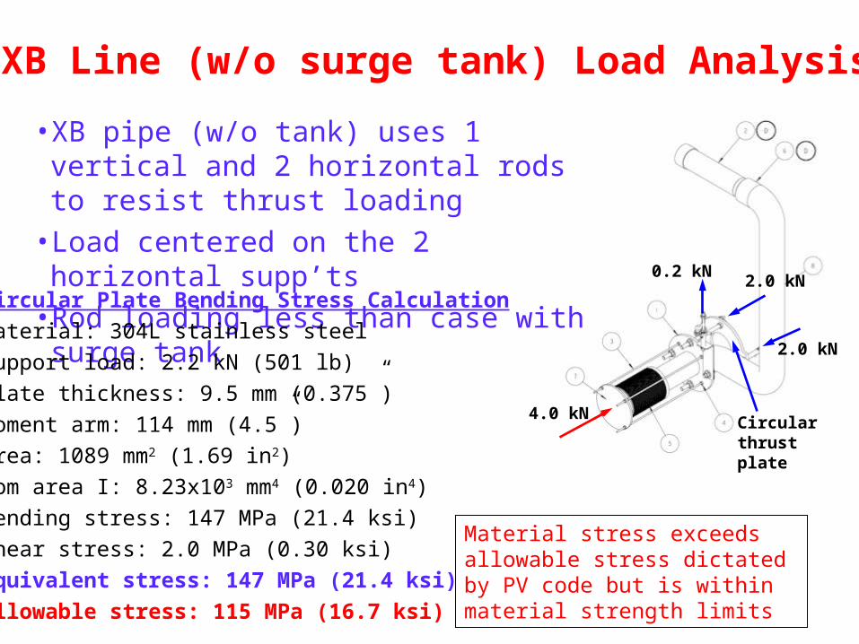
4.0 kN
2.0 kN
2.0 kN0.2 kN
• XB pipe (w/o tank) uses 1 vertical and 2 horizontal rods to resist thrust loading
• Load centered on the 2 horizontal supp’ts• Rod loading less than case with surge tank
Circular Plate Bending Stress Calculation
Material: 304L stainless steel
Support load: 2.2 kN (501 lb)
Plate thickness: 9.5 mm (0.375”)
Moment arm: 114 mm (4.5”)
Area: 1089 mm2 (1.69 in2)
Mom area I: 8.23x103 mm4 (0.020 in4)
Bending stress: 147 MPa (21.4 ksi)
Shear stress: 2.0 MPa (0.30 ksi)
Equivalent stress: 147 MPa (21.4 ksi)
Allowable stress: 115 MPa (16.7 ksi)
Circularthrustplate
Material stress exceeds allowable stress dictated by PV code but is within material strength limits
24 April 2007 DFBX 70
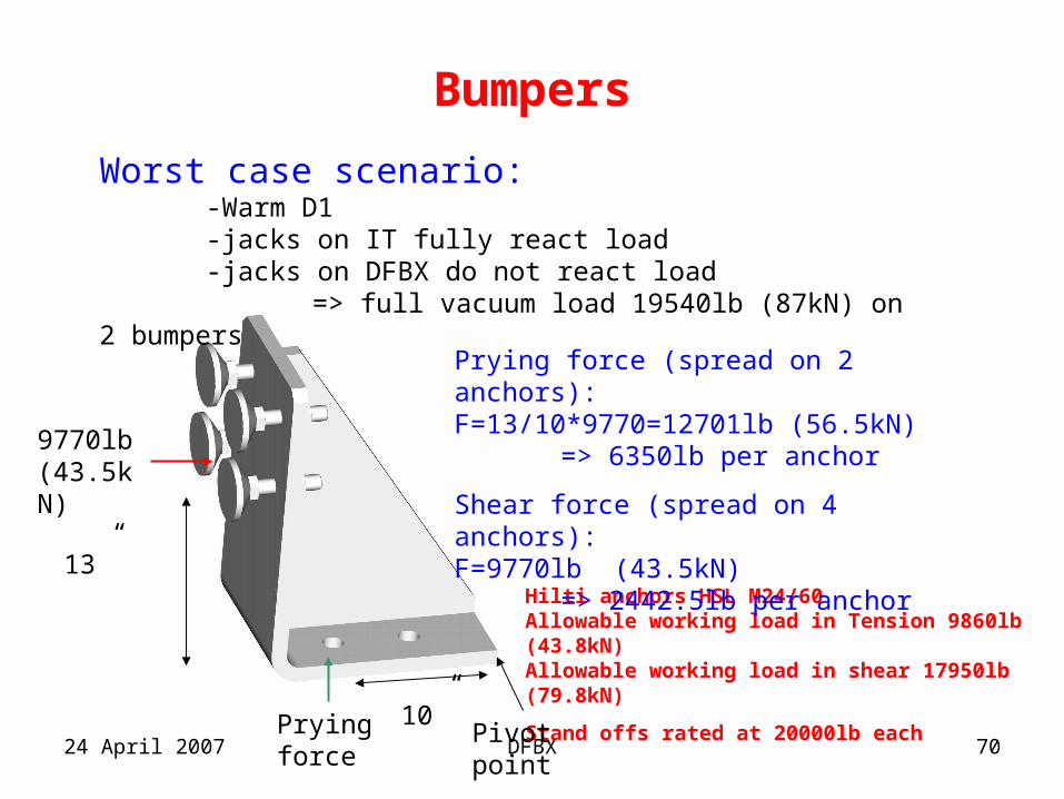
Bumpers
Hilti anchors HSL M24/60Allowable working load in Tension 9860lb (43.8kN)Allowable working load in shear 17950lb (79.8kN)
Stand offs rated at 20000lb each
9770lb(43.5kN)
Worst case scenario: -Warm D1 -jacks on IT fully react load-jacks on DFBX do not react load
=> full vacuum load 19540lb (87kN) on 2 bumpers
Prying force (spread on 2 anchors):F=13/10*9770=12701lb (56.5kN)
=> 6350lb per anchor
Shear force (spread on 4 anchors):F=9770lb (43.5kN)
=> 2442.5lb per anchor
Prying force
Pivot point
13”
10”
24 April 2007 DFBX 71
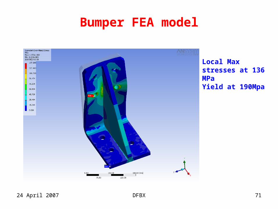
Bumper FEA model
Local Max stresses at 136 MPaYield at 190Mpa
24 April 2007 DFBX 72
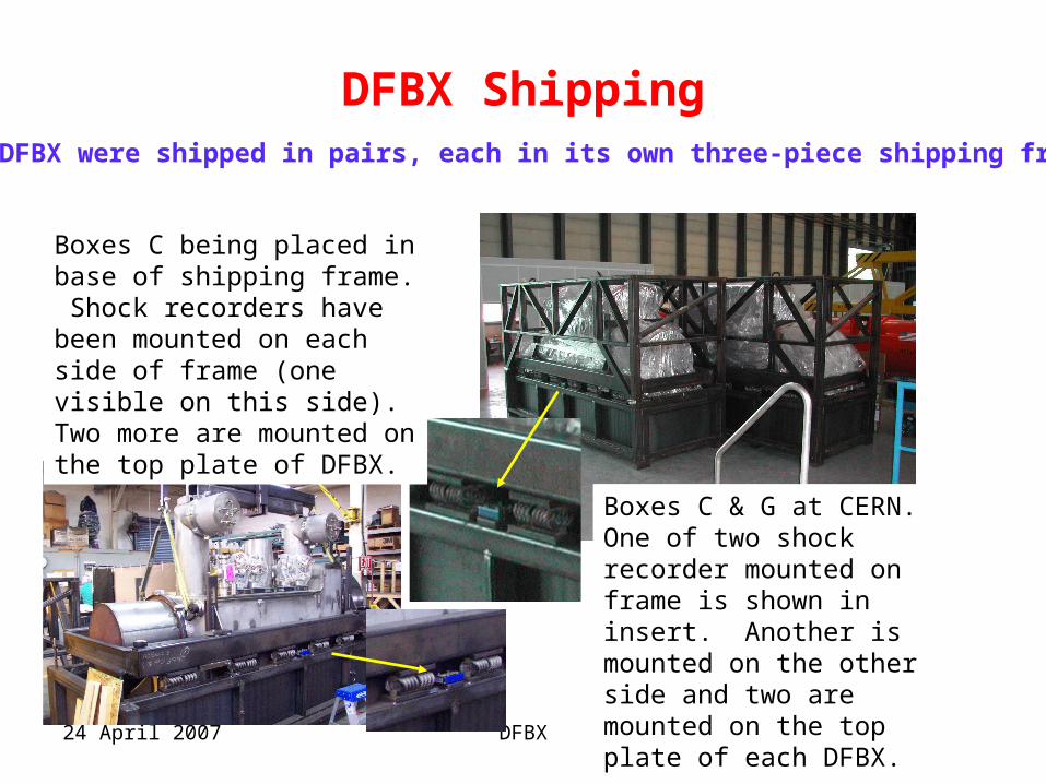
DFBX Shipping
Boxes C & G at CERN.One of two shock recorder mounted on frame is shown in insert. Another is mounted on the other side and two are mounted on the top plate of each DFBX.
Boxes C being placed in base of shipping frame. Shock recorders have been mounted on each side of frame (one visible on this side). Two more are mounted on the top plate of DFBX.
The DFBX were shipped in pairs, each in its own three-piece shipping frame
24 April 2007 DFBX 73
DFBX Summary• Detailed analyses were performed during design phase
based CERN requirements• Continued oversight during the fabrication phase to insure
that specifications were met• Cold shocks, pressure tests and vacuum leak checks were
performed at the component level at the manufacturer and CERN
• Analysis confirmed that the LHe vessel structure is robust• During the last month the DFBX mechanical structure was
reviewed and much of it was analyzed– FNAL organized two peer reviews
24 April 2007 DFBX 74
DFBX Conclusion• The analysis confirmed that the bus duct thrust
support is marginal– “Weld Clamp” was not welded– Support bracket is too thin
• Review and analysis of other components of the box revealed additional that should be upgraded– Eliminate LHe vessel vertical rods linkage dependence
on friction generated by bolt tightness
24 April 2007 DFBX 75
Future Activities• Continue reviewing and analyzing key aspect of
DFBX as built• Design and implement improved bust duct
support• Perform simulated thrust load tests• Review of all cooldown and warmup conditions to
look for potential interferences