dharam v. punwani president, avalon consulting, inc. v. punwani president, avalon consulting, inc....
TRANSCRIPT

Dharam V. Punwani
President, Avalon Consulting, Inc.
Presented at
Turbine Inlet Cooling Association Webinar
April 9, 2014
• Background: What is the problem that needs a solution?
• What is Turbine Inlet Cooling (TIC)?
• TIC Technologies
• Economic Benefits of TIC
• Environmental Benefits of TIC
• Factors Affecting the Performance of TIC Technologies
• Factors Affecting the Economics and Selection of TIC Technology
• Summary of the Presentation

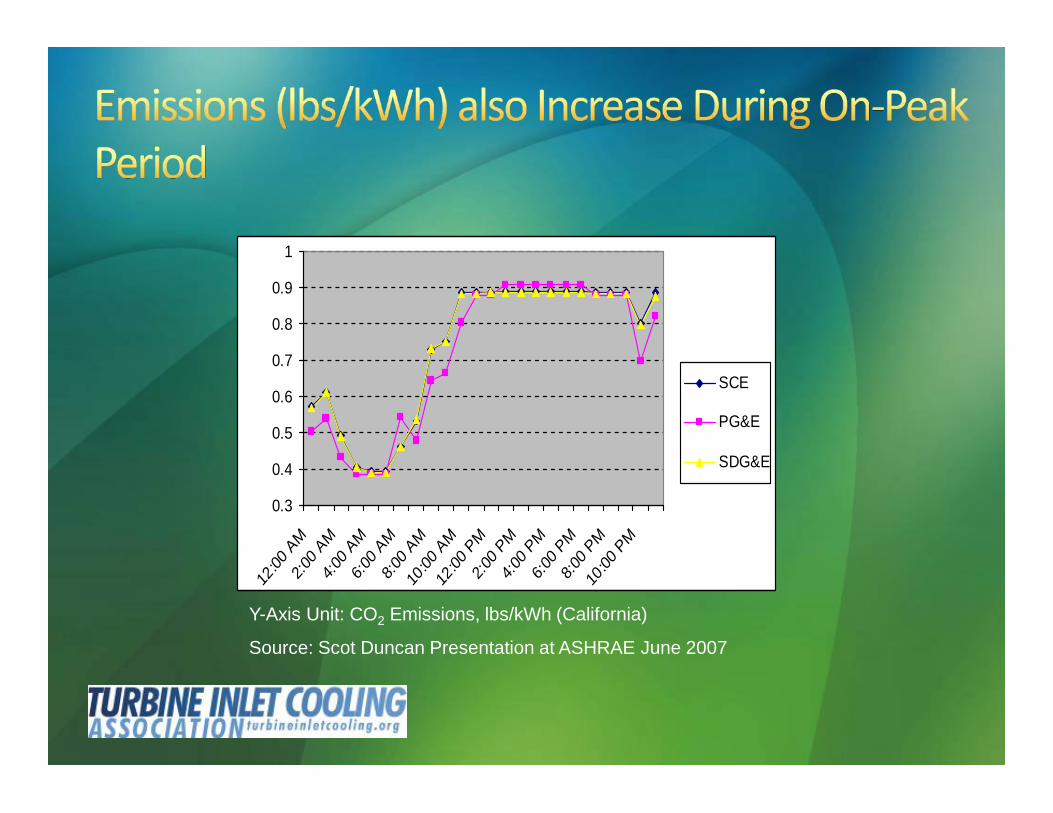
Price of electric energy for the ratepayers goes up during thepeak demand period: as much as 7 times that during the off-peak period
0.3
0.4
0.5
0.6
0.7
0.8
0.9
1
12:00
AM
2:00 A
M
4:00 A
M
6:00 A
M
8:00 A
M
10:00
AM
12:00
PM
2:00 P
M
4:00 P
M
6:00 P
M
8:00 P
M
10:00
PM
SCE
PG&E
SDG&E
Y-Axis Unit: CO2 Emissions, lbs/kWh (California)
Source: Scot Duncan Presentation at ASHRAE June 2007
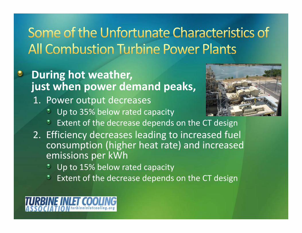
During hot weather,just when power demand peaks,1. Power output decreases
Up to 35% below rated capacityExtent of the decrease depends on the CT design
2. Efficiency decreases leading to increased fuelconsumption (higher heat rate) and increasedemissions per kWh
Up to 15% below rated capacityExtent of the decrease depends on the CT design
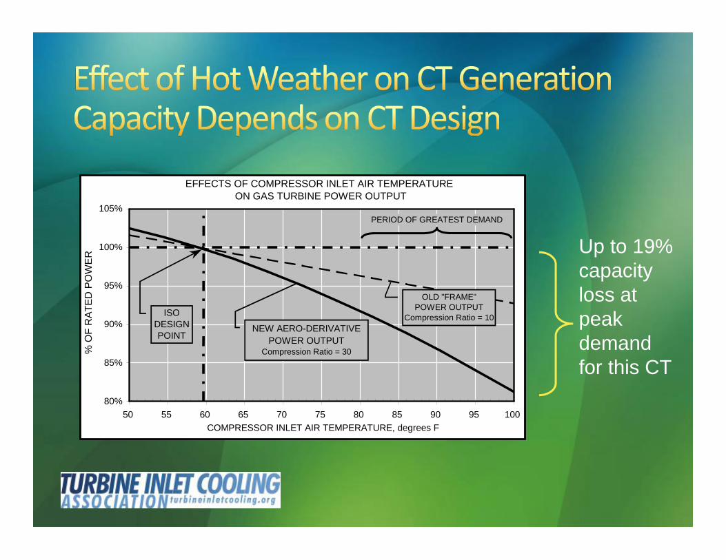
EFFECTS OF COMPRESSOR INLET AIR TEMPERATURE ON GAS TURBINE POWER OUTPUT
80%
85%
90%
95%
100%
105%
50 55 60 65 70 75 80 85 90 95 100COMPRESSOR INLET AIR TEMPERATURE, degrees F
% O
F R
ATE
D P
OW
ER
OLD "FRAME"POWER OUTPUT
Compression Ratio = 10
PERIOD OF GREATEST DEMAND
NEW AERO-DERIVATIVEPOWER OUTPUT
Compression Ratio = 30
ISODESIGNPOINT
Up to 19%capacityloss atpeakdemandfor this CT
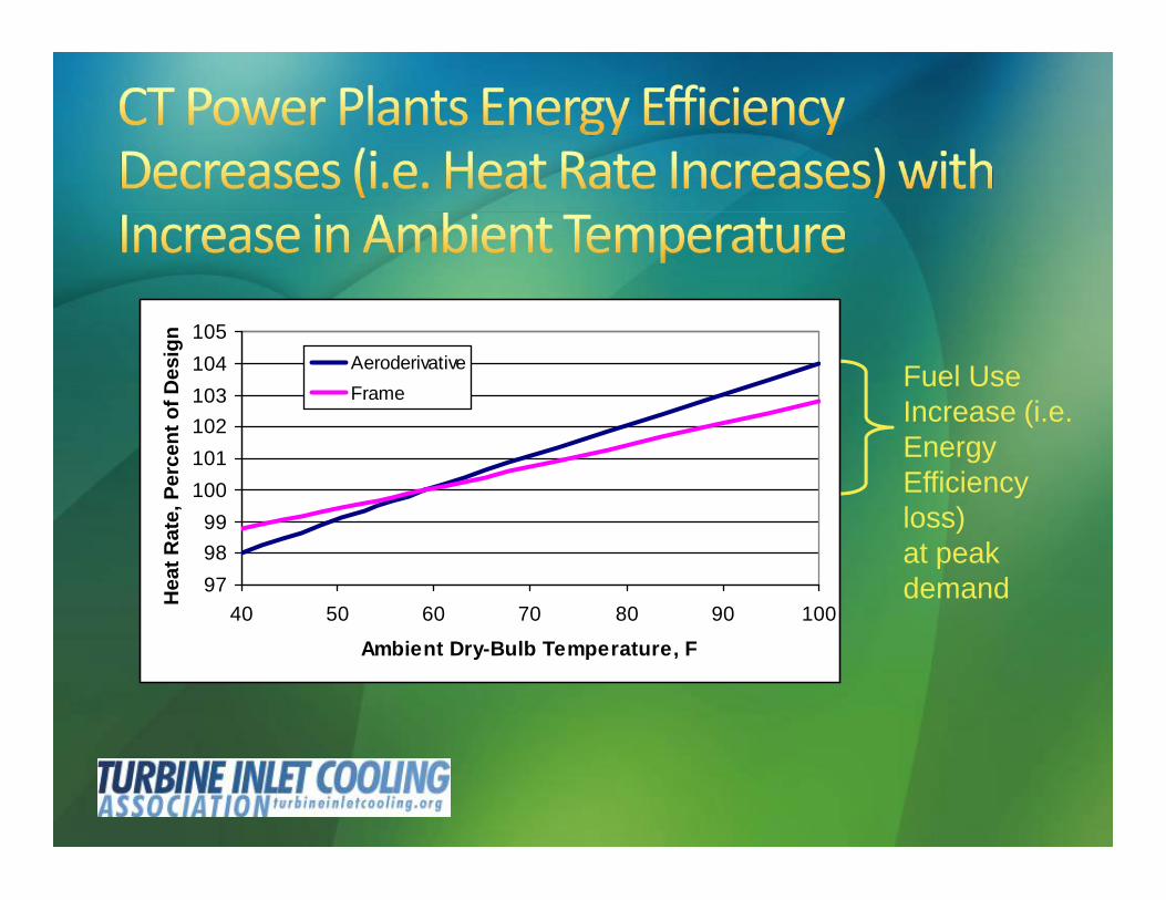
Fuel UseIncrease (i.e.EnergyEfficiencyloss)at peakdemand97
9899
100101102103104105
40 50 60 70 80 90 100
Ambient Dry-Bulb Temperature, F
Hea
t Rat
e, P
erce
nt o
f Des
ign
AeroderivativeFrame
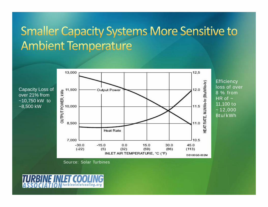
Source: Solar Turbines
Capacity Loss ofover 21% from~10,750 kW to~8,500 kW
Efficiencyloss of over8 % fromHR of ~11,100 to~12,000Btu/kWh
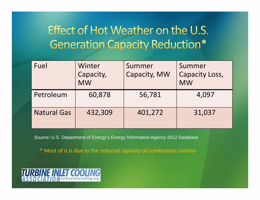
Fuel WinterCapacity,MW
SummerCapacity, MW
SummerCapacity Loss,MW
Petroleum 60,878 56,781 4,097
Natural Gas 432,309 401,272 31,037
Source: U.S. Department of Energy’s Energy Information Agency 2012 Database
* Most of it is due to the reduced capacity of combustion turbine
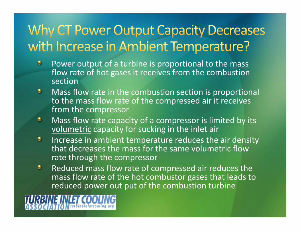
Power output of a turbine is proportional to the massflow rate of hot gases it receives from the combustionsectionMass flow rate in the combustion section is proportionalto the mass flow rate of the compressed air it receivesfrom the compressorMass flow rate capacity of a compressor is limited by itsvolumetric capacity for sucking in the inlet airIncrease in ambient temperature reduces the air densitythat decreases the mass for the same volumetric flowrate through the compressorReduced mass flow rate of compressed air reduces themass flow rate of the hot combustor gases that leads toreduced power out put of the combustion turbine
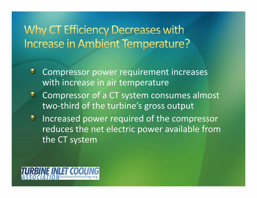
Compressor power requirement increaseswith increase in air temperatureCompressor of a CT system consumes almosttwo-third of the turbine’s gross outputIncreased power required of the compressorreduces the net electric power available fromthe CT system

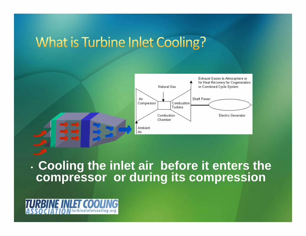
• Cooling the inlet air before it enters thecompressor or during its compression
16
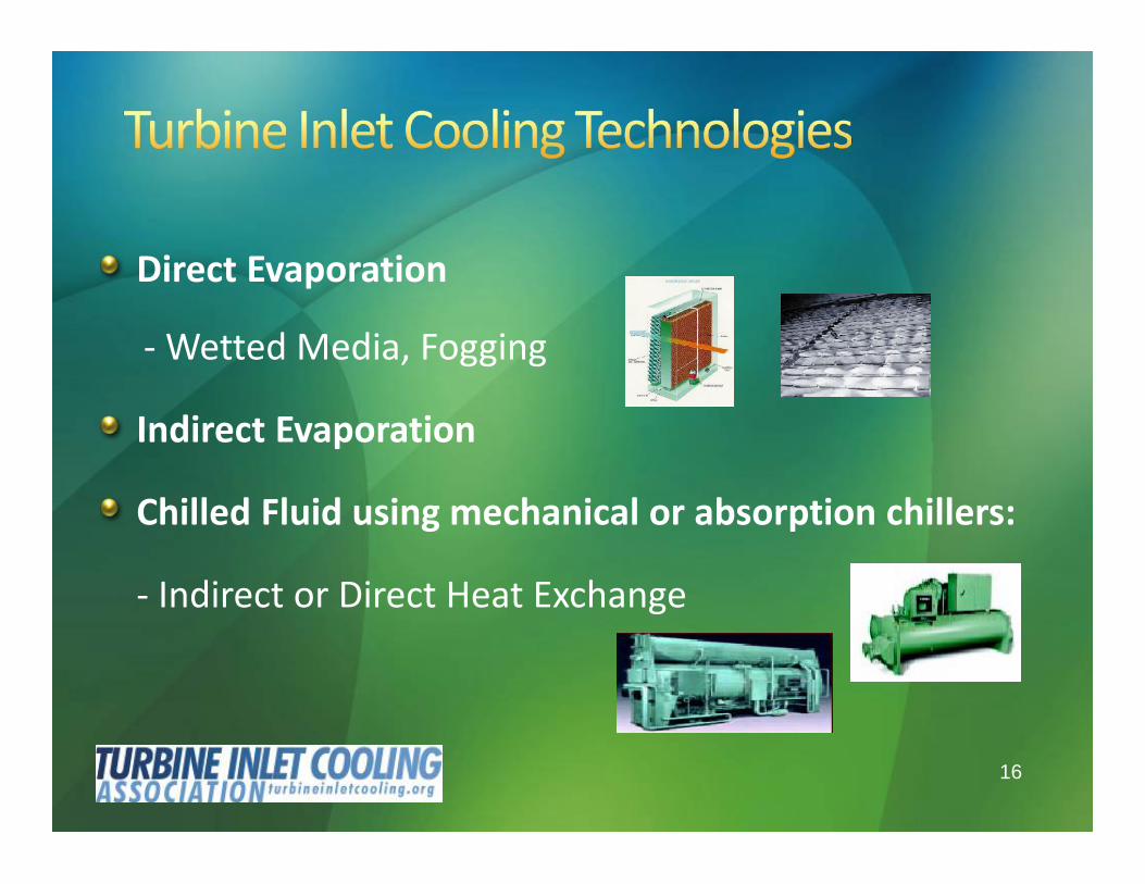
Direct Evaporation
- Wetted Media, Fogging
Indirect Evaporation
Chilled Fluid using mechanical or absorption chillers:
- Indirect or Direct Heat Exchange
17
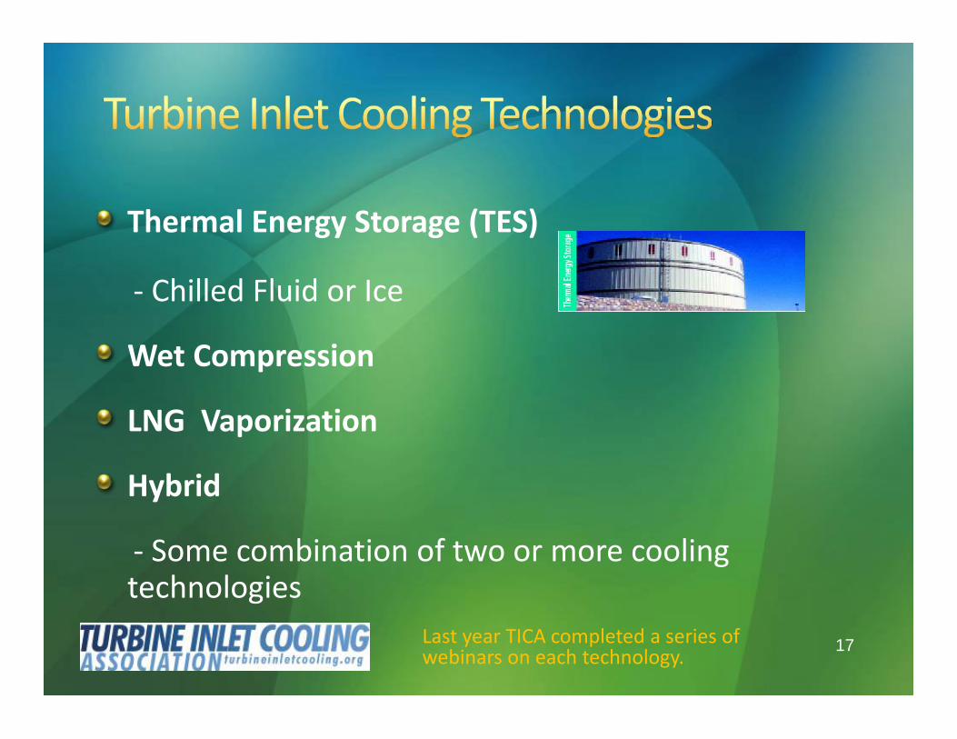
Thermal Energy Storage (TES)
- Chilled Fluid or Ice
Wet Compression
LNG Vaporization
Hybrid
- Some combination of two or more coolingtechnologies
Last year TICA completed a series ofwebinars on each technology.

Each TIC technology has its pros and cons
No one technology is best for all applications
Evaporative cooling systems can not cool theinlet air to lower than the wet-bulbtemperature but require least capital cost andhave least parasitic power need
Chiller systems can be designed to cool the airto any desired temperature but require morecapital cost and have high parasitic powerneed
TES systems shift chiller parasitic load to off-peak period
Wet compression improves compressionefficiency and low parasitic load
Hybrid systems minimize the parasitic load toachieve a desired inlet air temperature
LNG vaporization only applicable where thepower plant is located at/or need an LNGvaporization facility

Thousands of plants already benefiting fromTIC
TICA web site database of 100+ plantsworldwide that are using TICwww.turbineinletcooling.org/database.html

Available on the TICA Website
http://www.turbineinletcooling.org/calculation_nonmem.php5
Member Version (Full Version)
Public Version (Partial Features)
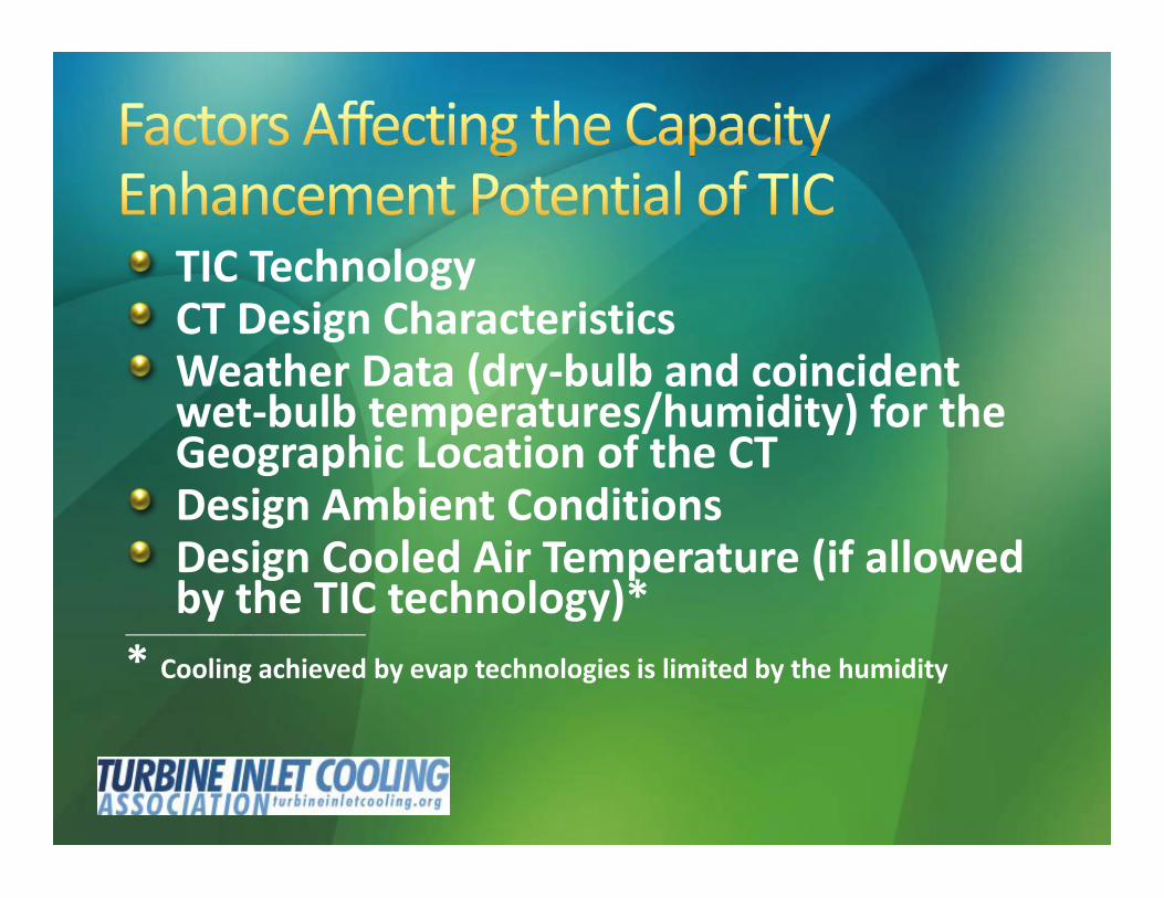
TIC TechnologyCT Design CharacteristicsWeather Data (dry-bulb and coincidentwet-bulb temperatures/humidity) for theGeographic Location of the CTDesign Ambient ConditionsDesign Cooled Air Temperature (if allowedby the TIC technology)*
_________________________________________
* Cooling achieved by evap technologies is limited by the humidity
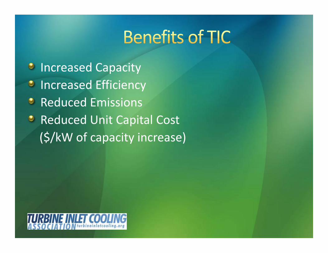
Increased CapacityIncreased EfficiencyReduced EmissionsReduced Unit Capital Cost($/kW of capacity increase)
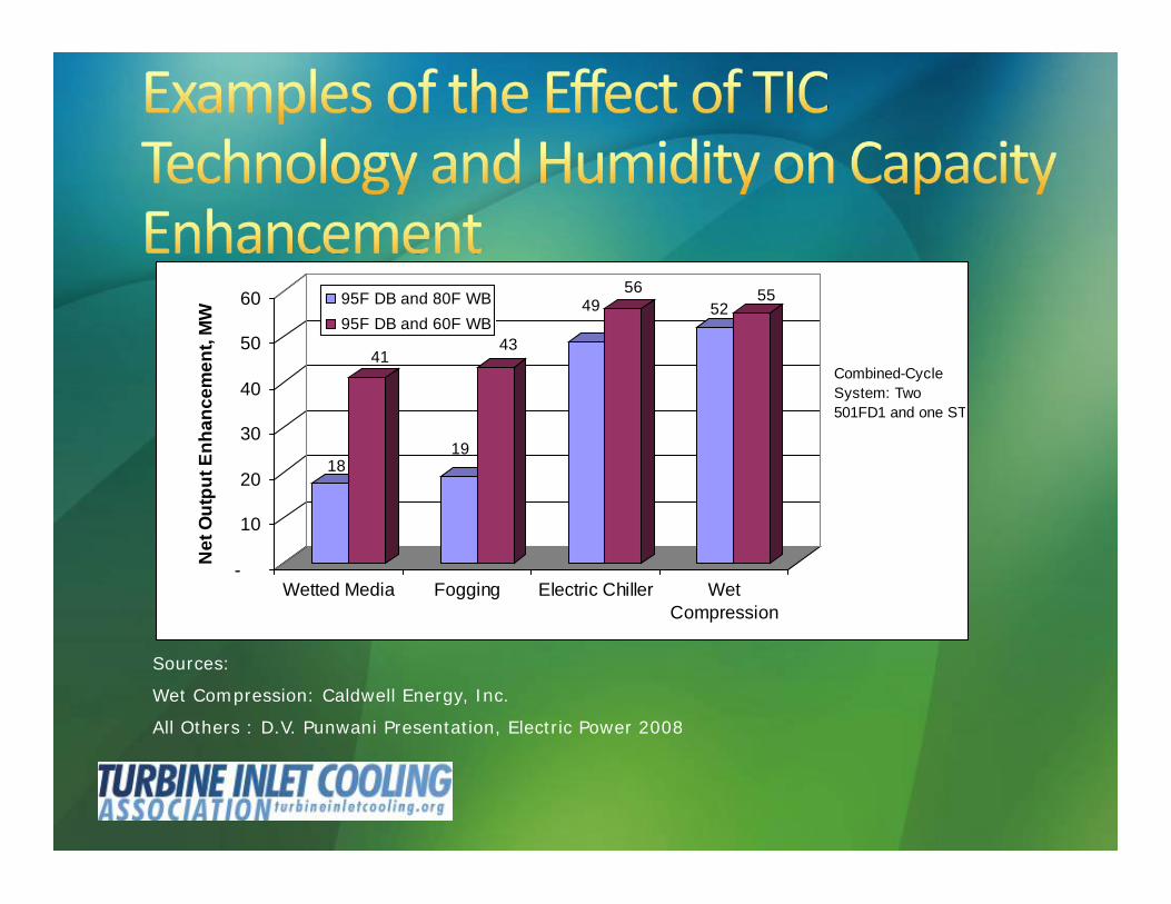
Sources:
Wet Compression: Caldwell Energy, Inc.
All Others : D.V. Punwani Presentation, Electric Power 2008
18
41
19
43
4956
5255
-
10
20
30
40
50
60
Net
Out
put E
nhan
cem
ent,
MW
Wetted Media Fogging Electric Chiller WetCompression
95F DB and 80F WB95F DB and 60F WB
Combined-CycleSystem: Two501FD1 and one ST

Reduces on-site emissions* by increasingthe efficiency of the turbine being cooled
Reduces grid-wide emissions* by reducingthe need for operating less-efficient andhigher-emission power plants
* lb/kWh of all emissions including, CO2, NOx, Sox
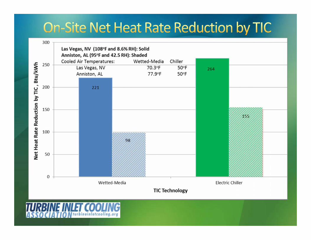
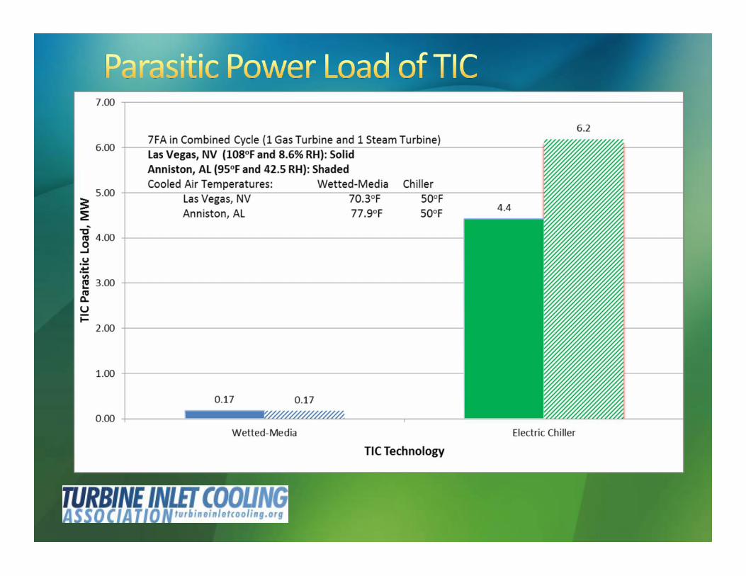
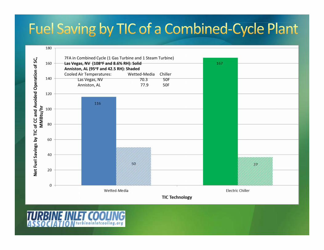
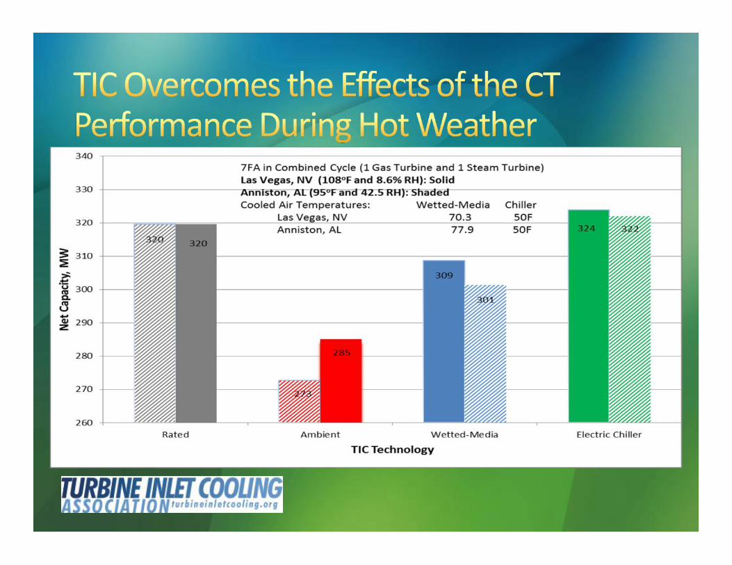
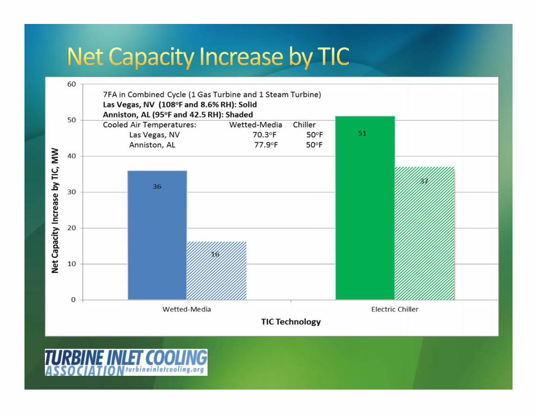
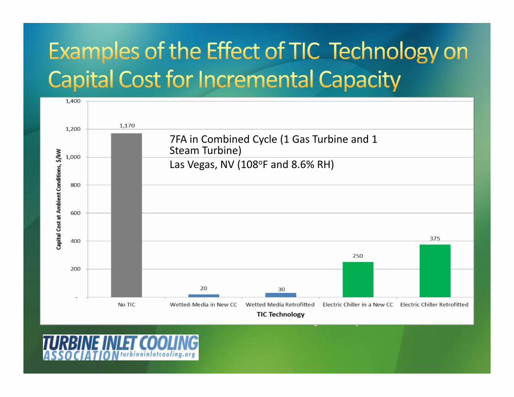
7FA in Combined Cycle (1 Gas Turbine and 1 Steam Turbine)Las Vegas, NV (108oF and 8.6% RH): SolidAnniston, AL (95oF and 42.5 RH): ShadedCooled Air Temperatures: Wetted-Media Chiller
Las Vegas, NV 70.3 50FAnniston, AL 77.9 50F
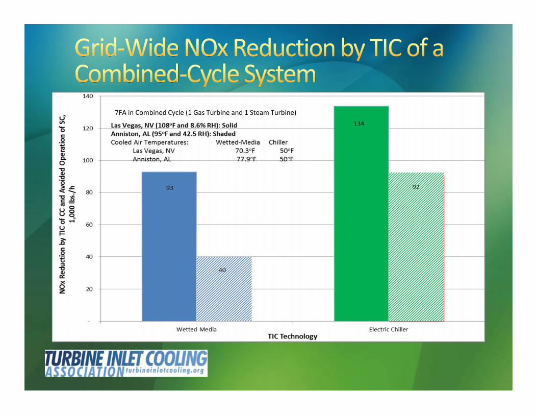
7FA in Combined Cycle (1 Gas Turbine and 1 Steam Turbine)

ExampleTIC on a nominal 500 MW CC plant eliminates theneed for siting a new or operating an existing 75-95MW SC peaker- Eliminates costs associated with siting,
construction and interconnections of a new plant- Reduce long lead time for a new plant (TIC
requires <1yr)

(316 MW Cogeneration Plant Near Houston, TX)
Source: D.V. Punwani et. al. Presented at ASHARE 2001
Evaporative Cooling is aWetted Media system
Single-Effect and Double-EffectRefer to Absorption Chillers
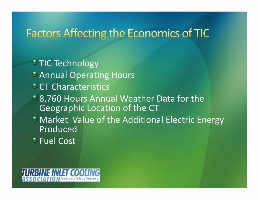
TIC TechnologyAnnual Operating HoursCT Characteristics8,760 Hours Annual Weather Data for theGeographic Location of the CTMarket Value of the Additional Electric EnergyProducedFuel Cost
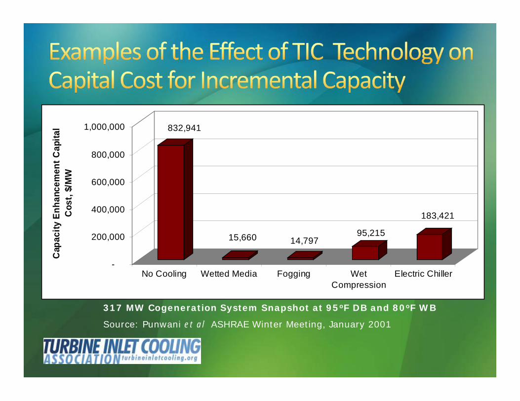
317 MW Cogeneration System Snapshot at 95oF DB and 80oF WB
Source: Punwani et al ASHRAE Winter Meeting, January 2001
832,941
15,660 14,79795,215
183,421
-
200,000
400,000
600,000
800,000
1,000,000
Cap
acity
Enh
ance
men
t Cap
ital
Cos
t, $/
MW
No Cooling Wetted Media Fogging WetCompression
Electric Chiller
317 MW Cogeneration System Snapshot at 95oF DB and 80oF WB
Source: Punwani et al ASHRAE Winter Meeting, January 2001
7FA in Combined Cycle (1 Gas Turbine and 1Steam Turbine)Las Vegas, NV (108oF and 8.6% RH)
Generates more MWh during peak demand periods whenelectric energy value is highReduces capital cost per unit of the increased generationcapacity compared to new power plantsReduces fuel cost of electric energy generation compared tothe low energy efficiency “peakers”Reduces cost for ratepayers by potentially lower capacitypayments to be provided by the independent systemoperators (ISOs) to power producers
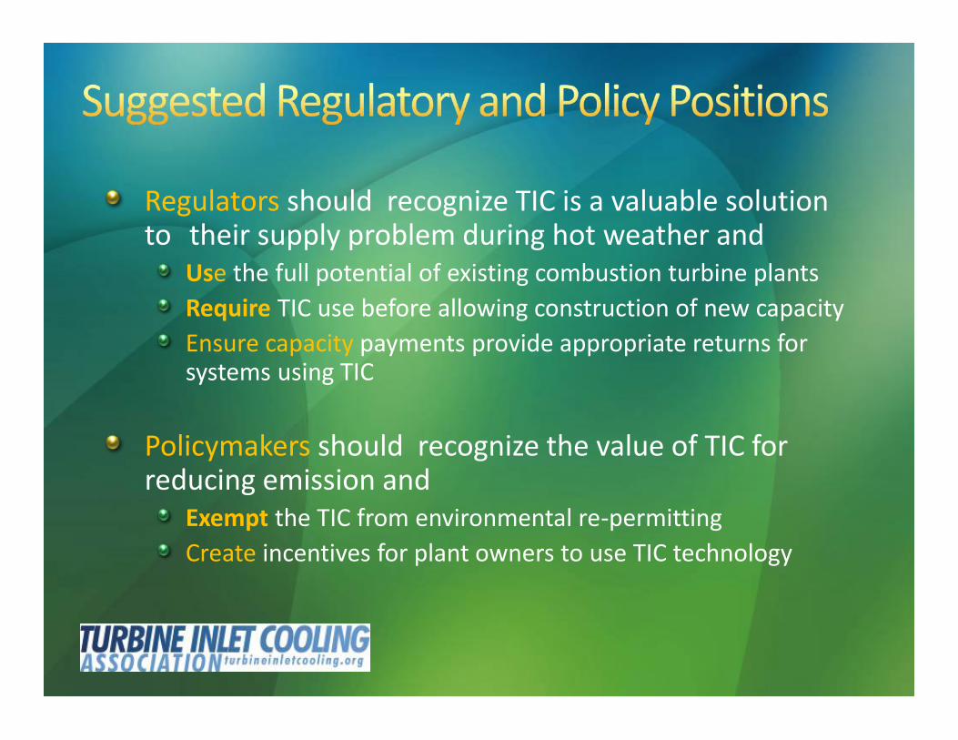
Regulators should recognize TIC is a valuable solutionto their supply problem during hot weather and
Use the full potential of existing combustion turbine plantsRequire TIC use before allowing construction of new capacityEnsure capacity payments provide appropriate returns forsystems using TIC
Policymakers should recognize the value of TIC forreducing emission and
Exempt the TIC from environmental re-permittingCreate incentives for plant owners to use TIC technology
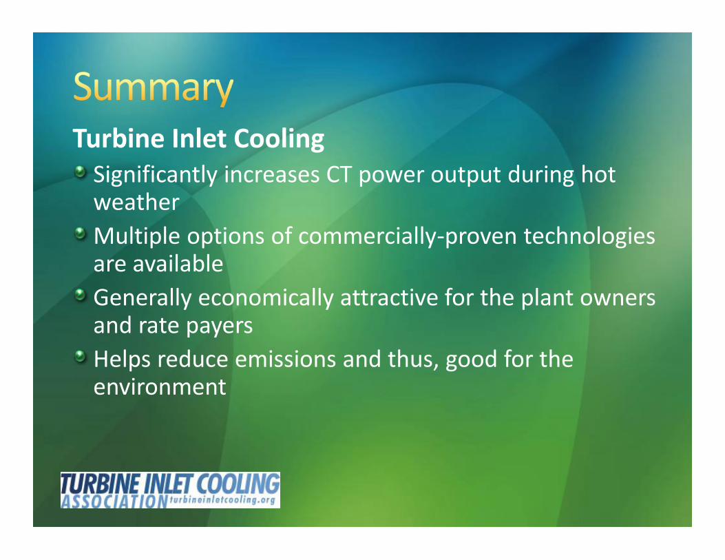
Turbine Inlet CoolingSignificantly increases CT power output during hotweatherMultiple options of commercially-proven technologiesare availableGenerally economically attractive for the plant ownersand rate payersHelps reduce emissions and thus, good for theenvironment

June 11, 2014: Wetted-Media Evaporative Cooling
August 13, 2014: FoggingOctober 8, 2014: Chiller Systems
December 12, 2014: Thermal Energy Storage
February 11, 2015: Wet Compression
April 8, 2015: Hybrid Systems