dhindaw al cu
TRANSCRIPT

Available online at www.sciencedirect.com
www.elsevier.com/locate/actamat
Acta Materialia 58 (2010) 122–133
Simulation of cooling of liquid Al–33 wt.% Cu droplet impingingon a metallic substrate and its experimental validation
A. Kumar a, S. Ghosh a,*, B.K. Dhindaw b
a Department of Metallurgical and Materials Engineering, Indian Institute of Technology, Kharagpur 721302, Indiab Indian Institute of Technology Ropar (Punjab), Nangal Road, Rupnagar 140001, India
Received 20 June 2009; received in revised form 25 August 2009; accepted 28 August 2009Available online 1 October 2009
Abstract
In the present work a model for heat transfer during collision of a falling liquid Al–33 wt.% Cu droplet on a 304 stainless steel sub-strate has been developed on a FLUENT 6.3.16 platform. The model simultaneously takes into account the fluid flow and heat transferin the liquid droplet and the surrounding gas, and the heat transfer in the substrate. The liquid–gas interface was tracked using the vol-ume of fluid method and the contact resistance between Al–33 wt.% Cu and the substrate was taken into account. The comprehensivemodel correctly predicted the total spread in the droplet. As per the predicted transient thermal field, the solidification front speedoscillated along the radius of the spread droplet. Based on the estimated front speeds at these locations and Jackson–Hunt plot forAl–33 wt.% Cu, the variation of interlamellar spacing along the radial direction was found. It matched well with the variation of theexperimentally measured interlamellar spacing at different locations along the radius.� 2009 Acta Materialia Inc. Published by Elsevier Ltd. All rights reserved.
Keywords: Eutectic; Alloy droplet; Substrate; Solidification; Modeling
1. Introduction
Spray forming or casting refers to the break-up of aliquid metal stream into variously sized droplets, propelledaway from the atomization region by fast flowing atomiz-ing gas to a substrate, where the droplets are deposited[1–3]. The flight and deposition of the droplet are accompa-nied by cooling and solidification, during which the coolingrate determines the structural features at the mesoscale,such as grain size, grain structure and eutectic spacing (inthe case of eutectic alloys). Thus, during the spray casting,desired structural features can be obtained by controllingthe rate of cooling within the droplets.
The cooling rate within the droplets, in turn, depends onthe processing parameters such as superheat of liquidmetal, size of the droplet, velocity of impingement and
1359-6454/$36.00 � 2009 Acta Materialia Inc. Published by Elsevier Ltd. All
doi:10.1016/j.actamat.2009.08.063
* Corresponding author. Tel.: +91 3222283294; fax: +91 3222282280.E-mail address: [email protected] (S. Ghosh).
thermal diffusivity of the substrate material, and thus thestructure of solidified material can be controlled by con-trolling these parameters. The processing condition forachieving the desired structure can be identified by a vali-dated comprehensive mathematical model that predictsthe flow and the thermal fields during the droplet deposi-tion. However, due to interaction of several complex phe-nomena, comprehensive modeling of the dropletdeposition is a challenging task. Further, the validationof the model is complicated due to the small size of thedroplet and the high cooling rates involved.
In the past, mathematical models which simulate theatomization and thermal history of gas atomized dropletsas a function of flight distance from the point of gas atom-ization to the point of deposition [4–6] have been developed.Gas atomization has been extensively modeled [7–13].Zeoli and Gu [12] developed a numerical model to simulatethe critical droplet break-up during the atomization. Inthis numerical model they coupled droplet break-up withthe flow field generated by high-pressure gas nozzle and
rights reserved.

A. Kumar et al. / Acta Materialia 58 (2010) 122–133 123
reported that this numerical model can provide quantitativeassessment of the atomization process. Recently Zeoli andGu [13] developed an isentropic plug nozzle (IPN) to reducethe shocks and maximize the kinetic energy being trans-ferred from the gas in order to instablize the melt stream.The performance of IPN was examined using a numericalmodel which includes gas flow dynamics, droplet atomiza-tion mechanism and particle tracking.
The in-flight thermal behavior during deposition over arotating substrate was modeled by Tinoco et al. [14]. Thecalculations were performed by solving the momentumand enthalpy equations for the gas. Ojha and coworkers[15] studied solidification of undercooled droplets duringatomization process. The predicted cooling rate was com-pared with the calculated cooling rate from the secondarydendrite arm spacing measurement. Zeoli et al. [16]described a numerical model which combines both coolingand break-up in single computation (integrated model).The dynamic history of droplets was solved as discretephase in Eulerian gas flow. The droplet solidification modelincorporated the detailed heat transfer mechanism of und-ercooling, recalescence, peritectic and segregated solidifica-tion during flight. The model establishes that the in-flightdistance is the major factor influencing the atomizationand solidification of droplets.
Several numerical models have been developed to simu-late impact and solidification of molten droplets on a coldsubstrate. Bennett and Poulikakos [17] and Kang et al. [18]studied droplet deposition assuming that solidificationstarts only after complete spreading of droplet in the formof a disk. Theoretical and experimental studies done byBennett and Poulikakos [17] showed that the thermal con-ductivity of the substrate significantly affects the coolingrate of the splat. However, they did not incorporate theconvection.
Using numerical models and experiments, Zhao et al.[19,20] studied heat transfer and fluid dynamics duringcollision of a liquid droplet on a substrate. They extendedthe earlier model of Fukai et al. [21] to account for therelevant convection and conduction heat transfer phe-nomena both in the droplet and in the substrate, in thecase when there is no solidification. Their results, there-fore, are applicable to the pre-solidification stage of theimpact process. Liu et al. [22] used a one-dimensionalsolidification model in conjunction with a two-phase flowcontinuum technique to track the moving liquid–solidboundary. The model, however, does not account forthe convection in the liquid and conduction in thesubstrate.
Trapaga et al. [23] used a commercially available code,FLOW-3D [24], to study the heat transfer and solidifica-tion phenomena during droplet impact. They assumedthat the substrate was isothermal, and neglected any ther-mal contact resistance at the liquid–solid interface. Ber-tagnolii et al. [25] used a finite element approach withan adaptive discretization technique to model the defor-mation of the droplet and evolution of the thermal field
within the splat. Their model, however, does not take intoaccount the solidification and heat transfer to the sub-strate. Waldvogel and Poulikakos [26] used a finite ele-ment model to simulate spreading and solidificationduring droplet impact.
A three-dimensional simulation of impingement of tindroplet was carried out by Kamnis et al. [27]. This modelwas based on a two-dimensional model of impact of tindroplet on stainless steel using volume of fluid technique(VOF) [28]. The VOF technique was employed along withsolidification to compute the tracking of dynamic impact,spreading, solidification, splashing and air entrapment ofsequentially impinging droplets over the substrate. Thenumerical model was validated with the results of high-speed camera photography of the tin droplet, and excellentagreement between simulation and experimental resultswere reported. In particular the finger formation, whichcannot be predicted by an axisymmetric model, and airentrapment could be predicted using the three-dimensionalmodel.
The heat transfer through the liquid metal substratecontact will have significant influence on the cooling rateof the impinging droplet. If the contact resistance is highthe cooling rate of the droplet will be low, even thoughthe substrate metal may have high conductivity and heatcapacity. Only a few investigators [27–32] have attemptedto estimate the contact resistance of the droplet–substratecontact.
Simulation of the process of impingement and solidifica-tion of a droplet by a comprehensive mathematical modelwould incorporate the following:
1. cooling in the droplet during flight;2. flow in the melt taking into account the surface tension;3. coupled solidification, heat transfer to the surrounding
gaseous atmosphere and substrate;4. solidification and undercooling;5. variation of physical properties with temperature.
In the models of droplet deposition of liquid metals on asolid substrate all these have not been simultaneouslyincorporated. Most of the models have not taken intoaccount the contact thermal resistance between the liquiddroplet and substrate. Further, very few have attemptedvalidation of the model.
In the present study a comprehensive mathematicalmodel for impingement of liquid Al–33 wt.% Cu alloy ona stainless grade 304 stainless steel substrate has beendeveloped. The model takes into account the coupled heattransfer in the liquid droplet, surrounding gaseous med-ium, solid substrate and the contact thermal resistancebetween the droplet and substrate. It further takes intoaccount solidification, natural convection, flow in the drop-let and the gaseous medium. The contact thermal resistancebetween the liquid alloy droplet and a grade 304 stainlesssteel substrate was estimated using an inverse approach.The model was experimentally validated.

124 A. Kumar et al. / Acta Materialia 58 (2010) 122–133
2. Mathematical modeling of droplet impingement
The present study aims at developing a mathematicalmodel of flow and heat transfer in a liquid metal which fallsfreely through gaseous medium and finally impinges on acold substrate. The modeling of phenomena is complexbecause it involves interactions among three phases, viz.,liquid metal, solid substrate and gaseous medium. Further,as the droplet falls under the action of gravity and impingeson the substrate, its shape changes rapidly with time.
Fig. 1 is a schematic sketch of the phenomenon. A drop-let, which is initially spherical, falls through gaseous med-ium and impinges on a substrate. Since the initial shapeof the droplet is assumed to be spherical, the fluid flowand the heat transfer are axisymmetric.
The following assumptions have been made while devel-oping the model:
1. The droplet initially had spherical geometry.2. The problem is axisymmetric about the axis shown in
Fig. 1.3. Impinge velocity of the droplet is perpendicular to the
plane of the substrate and there is no rotation of drop-let along the axis.
4. The flow of molten alloy and gas is laminar and incom-pressible. The velocity of gaseous media at domain wallsis zero.
5. Walls of the domain (Fig. 1) are assumed to be at ambi-ent temperature.
6. The heat transfer is dominated by convection and con-duction modes. Therefore, radiation from the dropletsurface to the surroundings is ignored.
7. To estimate thermal contact resistance a special solidmaterial has been defined. The conductivity of the spe-cial material is estimated from the measured value ofthe contact resistance.
8. Initial velocity field is zero.
Fig. 1. Schematic representation of the mathematical model of dropletdeposition.
2.1. Governing equations
Numerical simulations of the axisymmetric dropletdeposition processes were conducted by solving the two-dimensional (r–z) continuity, Navier–Stokes and energyequations. The volume of fluid (VOF) approach [33] wascoupled with Navier–Stokes and energy equations to trackthe surface of the impinging droplet on a fixed Eulerianstructured mesh.
The continuity or conservation of mass equation is givenby
1@
r@rðruÞ þ @v
@z¼ 0 ð1Þ
where u and v are velocity components in the r and z direc-tions, respectively. The momentum conservation equationsin r and z directions are
@u@tþ u
@u@rþ v
@u@z¼ � 1
q@P@rþ t
@2u@z2þ 1
r@
@rr@u@r
� �� u
r2
� �
þ gr þ Sr ð2Þ
@v@tþu
@v@rþ v
@v@z¼�1
q@P@zþ t
@2v@z2þ1
r@
@rr@v@r
� �� �þgzþSz
ð3Þwhere P, q, and t are pressure, density, and kinematic vis-cosity of the fluid, respectively, g represents gravitationalforce per unit mass and S represents any other source termor body force term. The interfacial tension was incorpo-rated in the Navier–Stokes equation as a body force term.Enthalpy–porosity formulation [34] was incorporated inthe solution scheme in order to handle the effects of solid-ification. The formulation is described below.
Solidification results in latent heat generation and amodified form of the energy equation, incorporating latentheat, was used. The modified energy equation is given by
@ðqHÞ@t
þr � ðquHÞ ¼ r � ðkrT Þ þ Sh ð4Þ
where H is the enthalpy per unit volume, k is thermal con-ductivity and Sh is the rate of energy generation per unitvolume. The enthalpy of the material was computed asthe sum of the sensible enthalpy, h, and the latent heat,DH. It is expressed as
H ¼ hþ DH ð5Þwhere
h ¼ href þZ T
T ref
cP dT ð6Þ
In Eq. (6) href is the sensible enthalpy at the reference tem-perature and cP is the specific heat at constant pressure.
The liquid fraction, b, is defined as
b ¼ 0 if T < T solidus
b ¼ 1 if T > T liquidus
b ¼ T�TsolidusT liquidus�Tsolidus if T solidus < T < T liquidus
ð7Þ

A. Kumar et al. / Acta Materialia 58 (2010) 122–133 125
The latent heat content can be written in terms of thelatent heat of freezing, L:
DH ¼ bL ð8Þ
The source term appearing on the right-hand side of Eq.(4) is given by
Sh ¼@ðqDHÞ@t
þrðquDHÞ ð9Þ
Due to high temperature difference between the dropletand substrate and the relatively low droplet velocity, vis-cous dissipation of heat was negligible and thus notincluded in the source term.
Solidification also results in phase change. Instead oftracking the interface, Al–33 wt.% Cu was assumed to bea single phase pseudo-porous medium whose porositywas proportional to the liquid fraction. Thus the porosityof this single phase pseudo-porous medium varied fromas low as 0 in the solidified region to maximum in the liquidregion. Since Al–33 wt.% Cu is a eutectic alloy a suddentransition in the porosity is expected at the solidificationfront. To avoid numerical difficulties associated with thissudden transition, the solidification front was assumed tobe a narrow band and the porosity was varied from 0 tothe maximum value over this band. The effect of porositywas incorporated in the momentum equations through amomentum source terms (Eqs. (2) and (3)). The momen-tum source term S is given by
S ¼ ð1� bÞ2
ðb3 þ eÞAmusht ð10Þ
where b denotes the liquid fraction, e is a small number(0.001) to avoid divisionby zero, Amush is the mushy zoneconstant, and t is the velocity term.
Table 1Thermo-physical properties of Al–33 wt.% Cu alloy.
Properties of Al–33 wt.% Cu used in model Value
Thermal conductivity (W m�1 K�1) Ks = 155Kl = 71
Density (kg m�3) qs = 3410ql = 3240
Solidus temperature (K) 821Liquidus temperature (K) 821Melting heat (J kg�1) 350,000Specific heat (J kg�1 K�1) Cs = 1070
Cl = 895Viscosity* (kg m�1 K�1) At 943 K = 1.001 � 10�3
[40]At 973 K = 8.624 � 10�4
[40]At 1023 K = 5.65 � 10�4
[40]Surface tension (N m�1) 0.868 [41]
s = solid; l = liquid.* Value of viscosity of Al–33 wt.% Cu has been calculated using Arrheniusequation: g ¼ g0 exp � E
RT
� �up to the solidus temperature.
2.2. Boundary and initial conditions
2.2.1. Boundary conditions
Since the problem is axisymmetric, only half of thedomain shown in Fig. 1 was considered in the computationdomain. Axis of symmetry was like a free-slip wall. Thenormal velocity was zero. The tangential velocity did nothave normal gradient. Thus along the axis of axisymmetryu = 0 and ov/or = 0. At the other boundaries u = 0 andv = 0. Since these boundaries are far away from the drop-let, the temperature at these boundaries was set equal to theambient temperature, i.e., 300 K.
2.2.2. Initial conditionsAll zones were initialized with a temperature of 300 K,
except the droplet. The droplet was given a pre-determinedhigher temperature. The initial velocities at every pointinside the domain were zero, except within the droplet,where it was set to �U0.
2.3. Discretization and the solution method
The above described model was simulated on a FLU-ENT 6.3.16. FLUENT 6.3.16 solves the above describedequations using a control volume approach, which is fullyimplicit in time and uses upwind differencing in space [35].A segregated solution algorithm [36] with a control vol-ume based technique was used in the numerical method.The pressure and velocity were coupled with a semi-impli-cit method for pressure linked equation (SIMPLE) algo-rithm [37,38], which uses a guess-and-correct procedurefor the calculation of pressure on the staggered gridarrangement.
3. Thermo-physical properties
Al–33 wt.% Cu alloy was selected as the alloy system fortwo reasons. Firstly the thermo-physical properties of thealloy are known, and secondly the Jackson–Hunt plot isavailable for the comparison. The simulation was carriedout for Al–33 wt.% Cu liquid droplets sizes of 100–1000 lm.
Table 1 gives the thermo-physical properties of the Al–33 wt.% Cu alloy used in the present model [39].
The contact resistance between Al–33 wt.% Cu and thegrade 304 stainless steel substrate was determined to a firstapproximation using an inverse approach, described in thefollowing section.
3.1. Determination of thermal contact resistance
In order to estimate the thermal contact resistance, twochromel–alumel thermocouples were introduced in thegrade 304 stainless steel channel; one was placed atthe outer wall of the channel and the other was placed in

Fig. 3. Computational domain along with the boundary conditions forcomputing the thermal field in the experimental set-up shown in Fig. 2.
126 A. Kumar et al. / Acta Materialia 58 (2010) 122–133
the central position of the channel cavity as shown inFig. 2. Subsequently Al–33 wt.% Cu alloy was melted inan electric resistance furnace and poured into the grade304 stainless steel channel. Temperatures in the castingwere monitored using thermocouples connected to a dataacquisition system (DAS). The temperature data at thetwo locations were used to estimate the thermal contactresistance at the interface of the wall and the liquid metalby matching them with the temperatures at the two posi-tions obtained from simulation.
The computational domain for the simulation alongwith the boundary conditions is shown in Fig. 3. The airgap between Al–33 wt.% Cu and stainless grade 304 stain-less steel channel has been assumed to be a solid layer withequivalent thermal resistance.
3.2. Initial conditions
The input of initial conditions was taken from theexperiment:
Initia channel wall temperature = 398 K.Liquid melt initial temperature = 956 K.Ambient temperature = 300 K.
4. Experimental validation of the model
4.1. Uniform droplet deposition process
The master alloy was prepared from a 99.96% pure Aland a 99.99% pure Cu by induction melting. The chemicalanalysis was carried out to confirm the composition of themaster alloy. Fig. 4 shows the schematic diagram of dropletdeposition process. Al–33 wt.% Cu alloy was used for thespray casting process. A metal charge of 50 g of masteralloy was heated in a crucible, under air atmosphere, to atemperature above the liquidus temperature. The cruciblewas made of quartz and was coated with alcohol soot to
Fig. 2. Schematic two-dimensional view of the experim
avoid reaction between the melt and quartz crucible. Thediameter of the melt delivery nozzle was 3 mm. The cruci-ble was fixed inside a resistance furnace. A graphite stopperwas placed on the delivery nozzle at the base of the cruci-ble. A thermocouple in the center of the crucible and thefurnace insulation allowed continuous measurement oftemperature. When a pre-determined temperature wasreached, typically 150 �C above the alloy liquidus, thegraphite stopper rod was removed and the molten metalflowed through the delivery nozzle. The molten metalstream flowed into the deposition chamber in the form ofmetal droplets which impinged upon the substrate andwere deposited.
The solidified droplets were prepared for metallographicexamination using standard metallographic procedure andetched with Keller’s reagent. The microstructures werestudied using a JEOL JSM-6480LV scanning electronmicroscope.
ental set-up for determination of contact resistance.
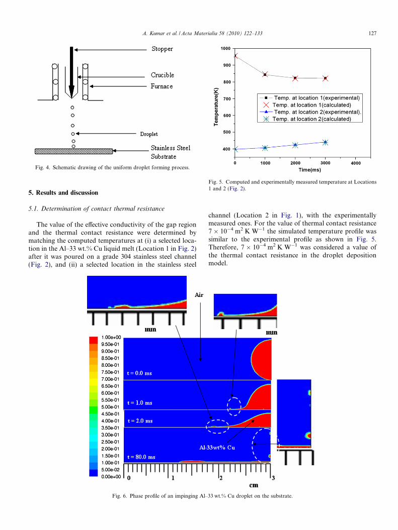
Fig. 4. Schematic drawing of the uniform droplet forming process.
Fig. 5. Computed and experimentally measured temperature at Locations1 and 2 (Fig. 2).
A. Kumar et al. / Acta Materialia 58 (2010) 122–133 127
5. Results and discussion
5.1. Determination of contact thermal resistance
The value of the effective conductivity of the gap regionand the thermal contact resistance were determined bymatching the computed temperatures at (i) a selected loca-tion in the Al–33 wt.% Cu liquid melt (Location 1 in Fig. 2)after it was poured on a grade 304 stainless steel channel(Fig. 2), and (ii) a selected location in the stainless steel
Fig. 6. Phase profile of an impinging Al–
channel (Location 2 in Fig. 1), with the experimentallymeasured ones. For the value of thermal contact resistance7 � 10�4 m2 K W�1 the simulated temperature profile wassimilar to the experimental profile as shown in Fig. 5.Therefore, 7 � 10�4 m2 K W�1 was considered a value ofthe thermal contact resistance in the droplet depositionmodel.
33 wt.% Cu droplet on the substrate.

128 A. Kumar et al. / Acta Materialia 58 (2010) 122–133
5.2. Simulation of droplet deposition
In the present study simulations were carried out for thedroplets, with diameters varying between 3.82 mm and8.18 mm falling through a height of 50 cm on a grade 304stainless steel substrate. As stated earlier, the shape of thedroplet impinging upon the substrate was assumed to bespherical and the cooling of droplet in the gaseous mediumduring the free fall was ignored. The assumption of insig-nificant temperature drop during flight was reasonable, asthe temperature drop during the period of flight is expectedto be negligible compared to that during the spreading.This was substantiated by an additional simulation of adroplet during its free fall through a height of 50 cm. In thissimulation the Weber number was �312. The shape of theAl–33 wt.% Cu droplets does not change significantly dur-ing flight. The substrate thickness was taken as low as1 mm in order to reduce the computational time. This willnot affect the accuracy of the prediction of the thermal fieldbecause during the short duration of droplet spreading andsolidification the temperature rise did not take placebeyond a distance of 0.3 mm.
Fig. 7. Velocity profile of the
The computed velocity, temperature, liquid fraction andphase (Al–33 wt.% Cu and air) fields after different periodsof time were plotted. Fig. 6 shows the phase contour of Al–33 wt.% Cu droplet having a diameter of 8.18 mm in air. Inthis case the velocity of impingement was 3.13 m s�1, andtherefore the Weber number was 302. The spread of thedroplet occurred within a short time frame of 8 � 10�3 sand no disintegration due to the surface tension forcewas observed. It can also be seen that the solidificationstarts 10�2 s after the spread has taken place. Fig. 7 alsoshows the velocity profile of Al–33 wt.% Cu/air system. Itcan be noted from the figure that air adjacent to Al–33 wt.% Cu is dragged in the direction of spread and are-circulating flow in air can be observed.
The evolution of the shape of liquid droplet impinging asolid substrate is a complex phenomenon. However, thishas been studied by many investigators [28,42–47]. Animportant parameter which decides upon the evolution ofshape of the liquid droplet is the Weber number, i.e., den-sity, viscosity, impingement velocity and surface tension.Depending on the Weber number, different types of shapeevolution are possible.
Al–33 wt.% Cu/air system.

A. Kumar et al. / Acta Materialia 58 (2010) 122–133 129
The simulated evolution of droplet shape (Fig. 6) hasbeen reported earlier [46]. The bump near the edge has beenobserved even when there is no cooling [42]. The physicalreasons for the bump formation are not fully clearalthough surface tension and the existence of the bumpbecause of the maximum cooling near the edge (Fig. 8)[46] could be suggested as two of the reasons.
The thermal contour in Fig. 8 shows convective coolingat the top surface, where Al–33 wt.% Cu is colder than theinner region. Similarly conductive cooling of Al–33 wt.%Cu near the substrate can be seen along with heating upof the substrate as shown in the temperature profile plotted(Fig. 8). Fig. 9 shows the liquid fraction within Al–33 wt.%Cu system.
Solidification front speed was estimated based on theliquid fraction profile at 20 different locations, 7 of which
Fig. 8. Temperature profile of an impinging
are shown in Fig. 10. Fig. 11a shows the variation of frontspeed with the radial distance. Interestingly the experimen-tally observed interlamellar spacing (Fig. 11b), which isrelated to the front speed by Jackson–Hunt relationship,also correlated with the radial distance in a similar manner.Fig. 11c and d shows the microstructure at the markedradial distance (Fig. 11b).
The variation front speed with the radial distance canbe explained in terms of variation of splat thickness withthe radial distance. Fig. 10 shows the different locationsin the splat along the radial direction. Fig. 11a showsthe growth rates at those locations. It can be observedthat the front speed is significantly less at thickerlocations (L3, L6, L12, L18, L19) and highest frontspeeds can be observed only at the thinnest locations(L9,L15).
Al–33 wt.% Cu droplet on the substrate.

Fig. 9. Liquid fraction profile of the Al–33 wt.% Cu/air system.
Fig. 10. Profile of the deformed droplet location for determination of the cooling rate at different positions.
130 A. Kumar et al. / Acta Materialia 58 (2010) 122–133
5.3. Sensitivity of font speed to variation in contact
resistance and natural convection
In order to study the sensitivity of front speed to varia-tion in contact resistance, the contact resistance was variedfrom 6.3 � 10�4 m2 K W�1 (10% less than experimentallydetermined value) to 7.7 � 10�4 m2 K W�1 (10% less thanexperimentally determined value). At the thicker locationsthe front speed was found to be insensitive to the contactresistance. However, at locations L9 and L15, which arethe thinnest locations, front speed is sensitive to the contactresistance. Thus it can be concluded that the variation inthe front speed along the radial direction is due to variationin the splat thickness.
Simulation was carried out where natural convection inboth Al–33 wt.% Cu and air was suppressed. The resultssuggest that natural convection did not play a significantrole as compared to the conduction through the substrate.
5.4. Effect of the initial temperature
Simulations were carried out for the two values of initialtemperature; viz., 875 K and 973 K. The initial temperaturehad a strong influence on the extent of spreading. Fig. 12shows the spread in diameter vs. time for 8.18 mm dropletshaving initial temperature of 875 K and 973 K. It can beseen that the spread increases with the increase in initialtemperature or the superheat. This is expected, as due to

A. Kumar et al. / Acta Materialia 58 (2010) 122–133 131
the rise in the initial temperature, both the fluidity and timerequired for the initiation of solidification increases.
Experimental validation of the simulated spreading wascarried out for 8.18 mm droplet having an initial tempera-ture of 973 K. 3.3 cm spread was observed in the droplet,which matches reasonably well with the predicted spread�3.7 cm.
The initial temperature of the droplet had a strong influ-ence on the front velocity. The front velocity significantlydecreased with increase in the initial temperature. The aver-age front speed (averaged over 7 locations, as shown inFig. 10) of 8.33 mm s�1 for initial droplet temperature of875 K dropped to 6.05 mm s�1 when the initial droplettemperature was increased to 973 K. Front speed is relatedto the microstructure and thus appropriate interlamellarspacing can be obtained by controlling the initial tempera-ture of the droplet.
Fig. 12. Effect of initial temperature on the spread.
5.5. Effect of the droplet diameter
Droplet diameter had a significant effect on the time tospread and front velocity. The time to spread increasedwith increase in the initial diameter of the droplet. This is
Fig. 11. Variation of (a) front speed with radial distance of droplet for differentemperature = 973 K, droplet diameter = 8.18 mm), (c) and (d) microstructure
as expected because the time to spread is expected toincrease with increase in the size of the droplet. Fig. 13shows the effect of the initial diameter of drops on theaverage solidification front speed for the initial droplet
t value of contact resistance, (b) measured interlamellar spacing (k) (initialof splat at marked radial distance.
132 A. Kumar et al. / Acta Materialia 58 (2010) 122–133
temperature of 973 K. The front speed initially increaseswith the diameter and then decreases.
5.6. Validation of the model
The present model is a comprehensive one that takesinto account the convective flows within and outside themelt, solidification effects, conductive heat transfer throughthe contact interface and the surface tension effects. Asmentioned earlier, Al–33 wt.% Cu was selected due toavailability of physical properties and also due to the factthat the simulated results can be validated using J–H plot.
The experimental validation was carried out only fordroplet with 8.18 mm diameter having a superheat of150 K (initial temperature = 973 K). The solidified dropletwas sectioned at seven different locations (Fig. 10) and thesectioned pieces were metallographically prepared to char-acterize the microstructure.
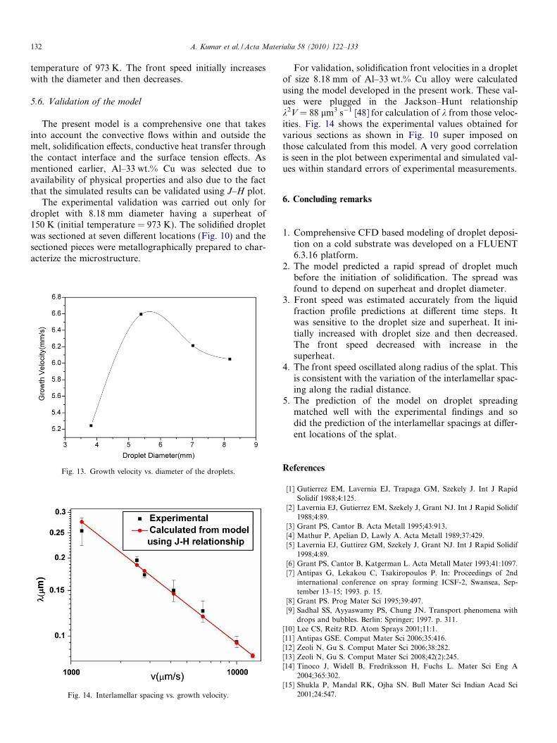
Fig. 13. Growth velocity vs. diameter of the droplets.
Fig. 14. Interlamellar spacing vs. growth velocity.
For validation, solidification front velocities in a dropletof size 8.18 mm of Al–33 wt.% Cu alloy were calculatedusing the model developed in the present work. These val-ues were plugged in the Jackson–Hunt relationshipk2V = 88 lm3 s�1 [48] for calculation of k from those veloc-ities. Fig. 14 shows the experimental values obtained forvarious sections as shown in Fig. 10 super imposed onthose calculated from this model. A very good correlationis seen in the plot between experimental and simulated val-ues within standard errors of experimental measurements.
6. Concluding remarks
1. Comprehensive CFD based modeling of droplet deposi-tion on a cold substrate was developed on a FLUENT6.3.16 platform.
2. The model predicted a rapid spread of droplet muchbefore the initiation of solidification. The spread wasfound to depend on superheat and droplet diameter.
3. Front speed was estimated accurately from the liquidfraction profile predictions at different time steps. Itwas sensitive to the droplet size and superheat. It ini-tially increased with droplet size and then decreased.The front speed decreased with increase in thesuperheat.
4. The front speed oscillated along radius of the splat. Thisis consistent with the variation of the interlamellar spac-ing along the radial distance.
5. The prediction of the model on droplet spreadingmatched well with the experimental findings and sodid the prediction of the interlamellar spacings at differ-ent locations of the splat.
References
[1] Gutierrez EM, Lavernia EJ, Trapaga GM, Szekely J. Int J RapidSolidif 1988;4:125.
[2] Lavernia EJ, Gutierrez EM, Szekely J, Grant NJ. Int J Rapid Solidif1988;4:89.
[3] Grant PS, Cantor B. Acta Metall 1995;43:913.[4] Mathur P, Apelian D, Lawly A. Acta Metall 1989;37:429.[5] Lavernia EJ, Guttirez GM, Szekely J, Grant NJ. Int J Rapid Solidif
1998;4:89.[6] Grant PS, Cantor B, Katgerman L. Acta Metall Mater 1993;41:1097.[7] Antipas G, Lekakou C, Tsakiropoulos P. In: Proceedings of 2nd
international conference on spray forming ICSF-2, Swansea, Sep-tember 13–15; 1993. p. 15.
[8] Grant PS. Prog Mater Sci 1995;39:497.[9] Sadhal SS, Ayyaswamy PS, Chung JN. Transport phenomena with
drops and bubbles. Berlin: Springer; 1997. p. 311.[10] Lee CS, Reitz RD. Atom Sprays 2001;11:1.[11] Antipas GSE. Comput Mater Sci 2006;35:416.[12] Zeoli N, Gu S. Comput Mater Sci 2006;38:282.[13] Zeoli N, Gu S. Comput Mater Sci 2008;42(2):245.[14] Tinoco J, Widell B, Fredriksson H, Fuchs L. Mater Sci Eng A
2004;365:302.[15] Shukla P, Mandal RK, Ojha SN. Bull Mater Sci Indian Acad Sci
2001;24:547.

A. Kumar et al. / Acta Materialia 58 (2010) 122–133 133
[16] Zeoli N, Gu S, Kamnis S. Int J Heat Mass Transfer 2008;51(15–16):4121.
[17] Bennett T, Poulikakos D. J Mater Sci 1994;29:2025.[18] Kang B, Zhao Z, PouLikakos D. ASME J Heat Transfer
1994;116:445.[19] Zhao Z, Poulikakos D, Fukai J. Int J Heat Mass Transfer
1996;39:2791.[20] Zhao Z, Poulikakos D, Fukai J. Int J Heat Mass Transfer
1996;39:2771.[21] Fukai J, Zhao Z, Poulikakos D, Megaxidis CM, Miyatake O. Phys
Fluids A 1993;5:2588.[22] Liu H, Lavernia EJ, Rangel RH. J Phys D: Appl Phys 1993;26:1900.[23] Trapaga G, Matthys EF, Valencia JJ, Szekely J. Met Trans B
1992;23:701.[24] FLOW-3D. Report No. FSI-88-00-1, vols. 1–4. Los Alamos, NM:
Flow Science Inc.; 1988.[25] Bertagnolii M, Marchese M, Jacucci G. J Therm Spray Technol
1995;4:41.[26] Waldvogel JM, Poulikakos D. Int J Heat Mass Transfer 1997;40:295.[27] Kamnis S, Gu S, Lu TJ, Chen C. J Phys D: Appl Phys
2008;41(16):165303.[28] Kamnis S, Gu S. J Phys D: Appl Phys 2005;38:3664.[29] Liu W, Wang GX, Int MatthysEF. J Heat Mass Transfer
1995;38:1387.[30] Wang GX, Matthys EF. J Heat Transfer 1996;118:157.[31] Chung M, Rangel RH. Numer Heat Transfer, Part A 2000;37:201.
[32] Shakeri S, Chandra S. Int J Heat Mass Transfer 2002;45:4561.[33] Sussman M, Smereka P, Osher S. J Comput Phys 1994;114:
146.[34] Voller VR, Prakash C. J Heat Mass Transfer 1987;30(8):1709.[35] Patankar SV. Numerical heat transfer and fluid flow. New
York: McGraw-Hill; 1980. p. 59.[36] Van Doormat JP, Raithby GD, McDonald BH. ASME J Turbomach
1987;109:268.[37] Peric M. Heat Transfer Part B: Fund 1990;17:63.[38] Raithby GD, Schneider GE. Numer Heat Transfer 1979;2:417.[39] Toloukian YS. Thermophysical properties of matter, vol. 1. New
York: IFI/Plenum; 1970.[40] Korolkov AM. Trans. from Russian, Consultants Bureau. New York;
1960 [p. 65].[41] Lang G. Aluminium 1974;50(11):731.[42] Sikalo S, Ganic EN. Exp Therm Fluid Sci 2006;31:97.[43] Fukumoto M, Nishikola E, Matsubara T. Surf Coat Technol
1999;120–121:131.[44] Zhang H. Int J Heat Mass Transfer 1999;42:2499.[45] Chung MO, Rangel RH. Int J Heat Mass Transfer 2001;44:605.[46] Fukai J, Ozaki T, Asami H, Miyatake O. J Chem Eng Jpn
2000;34(4):630.[47] Pasandideh-Fard M, Chandra S, Mostaghimi J. Int J Heat Mass
Transfer 2002;45:2229.[48] Jones H. Rapid solidification of metals and alloys. London: Institute
of Metallurgists; 1982.