diagnosis of automative electrical systems james d
TRANSCRIPT

9 781292 027463
ISBN 978-1-29202-746-3
Diagnosis of AutomativeElectrical Systems
James D. HaldermanSixth Edition
Diagnosis of A
utomative Electrical System
s Halderm
an Sixth Edition

Pearson Education LimitedEdinburgh GateHarlowEssex CM20 2JEEngland and Associated Companies throughout the world
Visit us on the World Wide Web at: www.pearsoned.co.uk
© Pearson Education Limited 2014
All rights reserved. No part of this publication may be reproduced, stored in a retrieval system, or transmitted in any form or by any means, electronic, mechanical, photocopying, recording or otherwise, without either the prior written permission of the publisher or a licence permitting restricted copying in the United Kingdom issued by the Copyright Licensing Agency Ltd, Saffron House, 6–10 Kirby Street, London EC1N 8TS.
All trademarks used herein are the property of their respective owners. The use of any trademark in this text does not vest in the author or publisher any trademark ownership rights in such trademarks, nor does the use of such trademarks imply any affi liation with or endorsement of this book by such owners.
ISBN 10: 1-269-37450-8ISBN 13: 978-1-269-37450-7
British Library Cataloguing-in-Publication DataA catalogue record for this book is available from the British Library
Printed in the United States of America
Copyright_Pg_7_24.indd 1 7/29/13 11:28 AM
ISBN 10: 1-292-02746-0ISBN 13: 978-1-292-02746-3
ISBN 10: 1-292-02746-0ISBN 13: 978-1-292-02746-3

CRANKING SYSTEM
The magnetic field of the starter motor is provided by two
or more pole shoes and field windings. The pole shoes are
made of iron and are attached to the frame with large screws.
� SEE FIGURE 8 . � FIGURE 9 shows the paths of magnetic flux lines within
a four-pole motor. The field windings are usually made of a heavy copper
ribbon to increase their current-carrying capacity and electro-
magnetic field strength. � SEE FIGURE 10 . Automotive starter motors usually have four pole shoes
and two to four field windings to provide a strong magnetic field
within the motor. Pole shoes that do not have field windings are
magnetized by flux lines from the wound poles.
FIGURE 5 The top button on this key fob is the remote start
button.
to reduce the possibility of theft. This feature allows the heat-
ing or air-conditioning system to start before the driver arrives.
� SEE FIGURE 5 .
NOTE: Most remote start systems will turn off the en-
gine after 10 minutes of run time unless reset by using
the remote.
STARTER MOTOR OPERATION
PRINCIPLES A starter motor uses electromagnetic prin-
ciples to convert electrical energy from the battery (up to
300 amperes) to mechanical power (up to 8 horsepower
[6 kilowatts]) to crank the engine. Current for the starter motor
or power circuit is controlled by a solenoid or relay, which is
itself controlled by the driver-operated ignition switch.
The current travels through the brushes and into the arma-
ture windings, where other magnetic fields are created around
each copper wire loop in the armature. The two strong magnetic
fields created inside the starter housing create the force that
rotates the armature.
Inside the starter housing is a strong magnetic field cre-
ated by the field coil magnets. The armature, a conductor, is
installed inside this strong magnetic field, with little clearance
between the armature and the field coils.
The two magnetic fields act together, and their lines of
force “bunch up” or are strong on one side of the armature
loop wire and become weak on the other side of the conductor.
This causes the conductor (armature) to move from the area of
strong magnetic field strength toward the area of weak mag-
netic field strength. � SEE FIGURES 6 AND 7 . The difference in magnetic field strength causes the ar-
mature to rotate. This rotation force (torque) is increased as
the current flowing through the starter motor increases. The
torque of a starter is determined by the strength of the magnetic
fields inside the starter. Magnetic field strength is measured in
ampere-turns. If the current or the number of turns of wire is
increased, the magnetic field strength is increased.
COMMUTATOR
NS
“HOT”BRUSH STARTER
CASEGROUND
GROUNDBRUSH
TO OUTPUTTERMINAL OFSOLENOID
POLESHOES
FIELDCOILS
FIGURE 6 This series-wound electric motor shows
the basic operation with only two brushes: one hot brush
and one ground brush. The current flows through both
field coils, then through the hot brush and the loop
winding of the armature, before reaching ground through
the ground brush.
FIELD COILMAGNETS
N
ONE “LOOP” OFARMATURECARRYING ACURRENT
S
“PILING UP” OFMAGNETIC LINESOF FORCE – FROMFIELD COIL ANDLINES SURROUNDINGARMATURE LOOPCONDUCTOR
�
FIGURE 7 The interaction of the magnetic fields of the arma-
ture loops and field coils creates a stronger magnetic field on
the right side of the conductor, causing the armature loop to
move toward the left.
192

CRANKING SYSTEM
(a)
(b)
(c)
(d)
N
ROTATION
S N
ROTATION
POLE SHOEPOLE SHOE
NS
DIRECTION OF CURRENTCONDUCTORMOTION
N
S
S
CONDUCTORMOTION
FIGURE 8 The armature loops rotate due to the difference in the
strength of the magnetic field. The loops move from a strong mag-
netic field strength toward a weaker magnetic field strength.
ARMATURE POLE SHOE
WINDINGSAIR GAP
N
N
S S
FIGURE 9 Magnetic lines of force in a four-pole motor.
POLE SHOE
FIELD WINDINGS
FIGURE 10 A pole shoe and field winding.
SERIES MOTORS A series motor develops its maximum
torque at the initial start (0 RPM) and develops less torque as
the speed increases.
� A series motor is commonly used for an automotive starter
motor because of its high starting power characteristics.
� A series starter motor develops less torque at high
RPM, because a current is produced in the starter itself
that acts against the current from the battery. Because
this current works against battery voltage, it is called
counterelectromotive force , or CEMF . This CEMF is pro-
duced by electromagnetic induction in the armature conduc-
tors, which are cutting across the magnetic lines of force
formed by the field coils. This induced voltage operates
against the applied voltage supplied by the battery, which
reduces the strength of the magnetic field in the starter.
� Because the power (torque) of the starter depends on the
strength of the magnetic fields, the torque of the starter
decreases as the starter speed increases. A series-
wound starter also draws less current at higher speeds
and will keep increasing in speed under light loads. This
could lead to the destruction of the starter motor unless
controlled or prevented. � SEE FIGURE 11 .
SHUNT MOTORS Shunt-type electric motors have the field
coils in parallel (or shunt) across the armature.
A shunt-type motor has the following features.
� A shunt motor does not decrease in torque at higher
motor RPM, because the CEMF produced in the
armature does not decrease the field coil strength.
193

CRANKING SYSTEM
ARMATURE
ASERIES COIL
�
FIGURE 11 This wiring diagram illustrates the construction
of a series-wound electric motor. Notice that all current flows
through the field coils, then through the armature (in series) be-
fore reaching ground.
ARMATURE
A
�
FIGURE 12 This wiring diagram illustrates the construction of
a shunt-type electric motor, and shows the field coils in paral-
lel (or shunt) across the armature.
ARMATURE
ASERIES COIL
�
SHUNT COIL
FIGURE 13 A compound motor is a combination of series
and shunt types, using part of the field coils connected electri-
cally in series with the armature and some in parallel (shunt).
DRIVE ENDHOUSING(END FRAME)
HOUSING(FIELDFRAME)
FIGURE 14 A typical starter motor showing the drive-end
housing.
� A shunt motor, however, does not produce as high a
starting torque as that of a series-wound motor, and is
not used for starters. Some small electric motors, such
as used for windshield wiper motors, use a shunt motor
but most use permanent magnets rather than
electromagnets.
� SEE FIGURE 12 .
PERMANENT MAGNET MOTORS A permanent magnet (PM) starter uses permanent magnets that maintain constant
field strength, the same as a shunt-type motor, so they have
similar operating characteristics. To compensate for the lack
of torque, all PM starters use gear reduction to multiply starter
motor torque. The permanent magnets used are an alloy of
neodymium, iron, and boron, and are almost 10 times more
powerful than previously used permanent magnets.
COMPOUND MOTORS A compound-wound, or compound,
motor has the operating characteristics of a series motor and a
shunt-type motor, because some of the field coils are connected
to the armature in series and some (usually only one) are con-
nected directly to the battery in parallel (shunt) with the armature.
Compound-wound starter motors are commonly used in
Ford, Chrysler, and some GM starters. The shunt-wound field
coil is called a shunt coil and is used to limit the maximum speed
of the starter. Because the shunt coil is energized as soon as
the battery current is sent to the starter, it is used to engage the
starter drive on older Ford positive engagement–type starters.
� SEE FIGURE 13 .
HOW THE STARTER MOTOR WORKS
PARTS INVOLVED A starter consists of the main structural
support of a starter called the main field housing , one end of
which is called a commutator-end (or brush-end) housing
and the other end a drive-end housing . The drive-end housing
contains the drive pinion gear, which meshes with the engine
flywheel gear teeth to start the engine. The commutator-end
plate supports the end containing the starter brushes. Through bolts hold the three components together. � SEE FIGURE 14 .
� Field coils. The steel housing of the starter motor con-
tains permanent magnets or four electromagnets that
are connected directly to the positive post of the battery
to provide a strong magnetic field inside the starter. The
four electromagnets use heavy copper or aluminum wire
wrapped around a soft-iron core, which is contoured to fit
against the rounded internal surface of the starter frame.
The soft-iron cores are called pole shoes . Two of the four
pole shoes are wrapped with copper wire in one direc-
tion to create a north pole magnet, and the other two pole
shoes are wrapped in the opposite direction to create a
south pole magnet. These magnets, when energized, cre-
ate strong magnetic fields inside the starter housing and,
therefore, are called field coils . The soft-iron cores (pole
shoes) are often called field poles . � SEE FIGURE 15 .
194

ARMATURE CORE
ARMATURE LAMINATION
ARMATURE SHAFT
ASSEMBLED ARMATURE
ARMATURE COREASSEMBLY
COMMUTATORARMATUREWINDING
FIGURE 16 A typical starter motor armature. The armature core is made from thin sheet metal sections assembled on the arma-
ture shaft, which is used to increase the magnetic field strength.
POLE SHOE
FIELDCOIL
POLE SHOEMOUNTING SCREW
FIGURE 15 Pole shoes and field windings installed in the
housing.
LAP WINDING
CONDUCTOR SOUTHPOLE
NORTHPOLE
BRUSHES
BAR� �
FIGURE 17 An armature showing how its copper wire loops
are connected to the commutator.
� Armature. Inside the field coils is an armature that
is supported with either bushings or ball bearings at
both ends, which permit it to rotate. The armature is
constructed of thin, circular disks of steel laminated
together and wound lengthwise with heavy-gauge
insulated copper wire. The laminated iron core
supports the copper loops of wire and helps
concentrate the magnetic field produced by the
coils. � SEE FIGURE 16 .
Insulation between the laminations helps to increase the
magnetic efficiency in the core. For reduced resistance,
the armature conductors are made of a thick copper wire.
The two ends of each conductor are attached to two adjacent
commutator bars.
The commutator is made of copper bars insulated from
each other by mica or some other insulating material. � SEE FIGURE 17 .
The armature core, windings, and commutator are assem-
bled on a long armature shaft. This shaft also carries the pinion
gear that meshes with the engine flywheel ring gear.
STARTER BRUSHES To supply the proper current to the
armature, a four-pole motor must have four brushes riding on
the commutator. Most automotive starters have two grounded
and two insulated brushes, which are held against the commu-
tator by spring force.
The ends of the copper armature windings are soldered
to commutator segments . The electrical current that passes
through the field coils is then connected to the commutator
of the armature by brushes that can move over the segments
of the rotating armature. These brushes are made of a combi-
nation of copper and carbon.
� The copper is a good conductor material.
� The carbon added to the starter brushes helps provide
the graphite-type lubrication needed to reduce wear
of the brushes and the commutator segments.
The starter uses four brushes—two brushes to transfer the
current from the field coils to the armature, and two brushes to
provide the ground return path for the current that flows through
the armature.
CRANKING SYSTEM
195
CRANKING SYSTEM
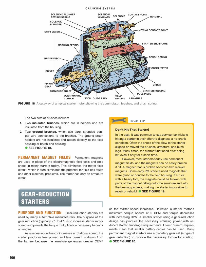
The two sets of brushes include:
1. Two insulated brushes , which are in holders and are
insulated from the housing.
2. Two ground brushes , which use bare, stranded cop-
per wire connections to the brushes. The ground brush
holders are not insulated and attach directly to the field
housing or brush-end housing.
� SEE FIGURE 18 .
PERMANENT MAGNET FIELDS Permanent magnets
are used in place of the electromagnetic field coils and pole
shoes in many starters today. This eliminates the motor field
circuit, which in turn eliminates the potential for field coil faults
and other electrical problems. The motor has only an armature
circuit.
as the starter speed increases. However, a starter motor’s
maximum torque occurs at 0 RPM and torque decreases
with increasing RPM. A smaller starter using a gear-reduction
design can produce the necessary cranking power with re-
duced starter amperage requirements. Lower current require-
ments mean that smaller battery cables can be used. Many
permanent magnet starters use a planetary gear set (a type of
gear reduction) to provide the necessary torque for starting.
� SEE FIGURE 20 .
DRIVER
BRUSH
COMMUTATOR
STARTER HOUSINGPOLE PIECE
ARMATURE
SOLENOIDWINDINGS SOLENOID
PINIONGEAR
CONTACT POINT
FIELDWINDINGGUIDE RINGSTOP
OVERRUNNINGCLUTCH
SOLENOID PLUNGERRETURN SPRING
MOVING CONTACT POINT
ARMATURE SHAFT
BRUSH SPRING
TERMINAL
SHIFT LEVER
SOLENOIDPLUNGER
MESHING SPRING
BRAKE DISC
STARTER END FRAME
FIGURE 18 A cutaway of a typical starter motor showing the commutator, brushes, and brush spring.
GEAR-REDUCTION STARTERS
PURPOSE AND FUNCTION Gear-reduction starters are
used by many automotive manufacturers. The purpose of the
gear reduction (typically 2:1 to 4:1) is to increase starter motor
speed and provide the torque multiplication necessary to crank
an engine.
As a series-wound motor increases in rotational speed, the
starter produces less power, and less current is drawn from
the battery because the armature generates greater CEMF
Don’t Hit That Starter!
In the past, it was common to see service technicians
hitting a starter in their effort to diagnose a no-crank
condition. Often the shock of the blow to the starter
aligned or moved the brushes, armature, and bush-
ings. Many times, the starter functioned after being
hit, even if only for a short time.
However, most starters today use permanent
magnet fields, and the magnets can be easily broken
if hit. A magnet that is broken becomes two weaker
magnets. Some early PM starters used magnets that
were glued or bonded to the field housing. If struck
with a heavy tool, the magnets could be broken with
parts of the magnet falling onto the armature and into
the bearing pockets, making the starter impossible to
repair or rebuild. � SEE FIGURE 19 .
TECH TIP
196