diagnostic repeater for profibus-dp
DESCRIPTION
Repeater for PROFIBUS-DP, how to use and configure.TRANSCRIPT

Preface, Contents
Product Overview 1
Functions 2
Configuration Options 3
Installation 4
Wiring 5
Commissioning 6
Diagnostics 7
Technical Specifications 8
Appendices
Order Numbers A
Dimension Drawings B
User Questions CGlossary, Index
SIMATIC
Diagnostic Repeaterfor PROFIBUS-DP
Manual
This manual has the order number:6ES7972-0AB00-8BA0
Edition 12/2002A5E00103899-02
The following supplement is part of this documentation:
No. Product Information Drawing number
Edition
1 Use of subassemblies/modules in a Zone 2 Hazardous Area
A5E00352937-03 12/2006
2 DP cycle time measurement; Time synchronization; Support of the I&M function; Firmware update; Supplement to the manual
A5E00821386-01 07/2006

Copyright © Siemens AG 2001-2002 All rights reservedThe reproduction, transmission or use of this document or itscontents is not permitted without express written authority.Offenders will be liable for damages. All rights, including rightscreated by patent grant or registration of a utility model or design,are reserved.
Siemens AGBereich Automation and DrivesGeschaeftsgebiet Industrial Automation SystemsPostfach 4848, D- 90327 Nuernberg
Disclaimer of LiabilityWe have checked the contents of this manual for agreement withthe hardware and software described. Since deviations cannot beprecluded entirely, we cannot guarantee full agreement. However,the data in this manual are reviewed regularly and any necessarycorrections included in subsequent editions. Suggestions forimprovement are welcomed.
©Siemens AG 2002Technical data subject to change.
Siemens Aktiengesellschaft A5E00103899-02
Safety Guidelines
This manual contains notices intended to ensure personal safety, as well as to protect the products andconnected equipment against damage. These notices are highlighted by the symbols shown below andgraded according to severity by the following texts:
! Dangerindicates that death, severe personal injury or substantial property damage will result if properprecautions are not taken.
! Warningindicates that death, severe personal injury or substantial property damage can result if properprecautions are not taken.
! Cautionindicates that minor personal injury can result if proper precautions are not taken.
Cautionindicates that property damage can result if proper precautions are not taken.
Noticedraws your attention to particularly important information on the product, handling the product, or to aparticular part of the documentation.
Qualified Personnel
Only qualified personnel should be allowed to install and work on this equipment. Qualified persons aredefined as persons who are authorized to commission, to ground and to tag circuits, equipment, andsystems in accordance with established safety practices and standards.
Correct Usage
Note the following:
! WarningThis device and its components may only be used for the applications described in the catalog or thetechnical description, and only in connection with devices or components from other manufacturerswhich have been approved or recommended by Siemens.
This product can only function correctly and safely if it is transported, stored, set up, and installedcorrectly, and operated and maintained as recommended.
Trademarks
SIMATIC®, SIMATIC HMI® and SIMATIC NET® are registered trademarks of SIEMENS AG.
Third parties using for their own purposes any other names in this document which refer to trademarks mightinfringe upon the rights of the trademark owners.

Diagnostic Repeater for PROFIBUS-DPA5E00103899-02 iii
Preface
Purpose of the manualThis manual provides an overview of the diagnostic repeater for PROFIBUS-DP. Itsupports you in the configuration, installation and commissioning.It is intended for persons working in the fields of configuring, commissioning andservicing automation systems.
Required knowledgeA general knowledge of automation technology is required in order to understandthe manual.
Validity of the manualThe manual is valid for the diagnostic repeater for PROFIBUS-DP with the ordernumber 6ES7 972-0AB01-0XA0.
Changes since the previous versionThe following chapters have been revised and added to since the previous editionof the manual "Diagnostic Repeater for PROFIBUS-DP":
• Chapter 2, "Functions"
• Chapter 3, "Configuration Options"
• Chapter 7, "Diagnostics"
• Chapter 8, "Technical Specifications"
Note: You can identify the previous version of this manual by its number in thefooter on each page: A5E00103899-01.
The number now is: A5E00103899-02.
Preface
Diagnostic Repeater for PROFIBUS-DPiv A5E00103899-02
ApprovalsSee Chapter 8.1, Standards and Approvals.
CE markingSee Chapter 8.1, Standards and Approvals.
Marking for Australia (C-Tick Mark)See Chapter 8.1, Standards and Approvals.
StandardsSee Chapter 8.1, Standards and Approvals.
Preface
Diagnostic Repeater for PROFIBUS-DPA5E00103899-02 v
GuideIn order to facilitate rapid access to special information the manual has thefollowing access aids:
• The manual begins with a table of contents.
• The chapters contain intermediate headlines which provide an overview of thecontents of the section.
• At the end of the appendix there is a glossary which defines the technicalterms used in the manual.
• At the end of the manual there is a detailed index which allows you rapidaccess to the desired information.
• You can get direct access to information on the diagnostic repeater on theInternet athttp://www.siemens.com/Diagnostic-Repeater
Recycling and disposalThe diagnostic repeater is low in contaminants and can thus be recycled. Torecycle and dispose of your old equipment in an environmentally friendly manner,contact a company that is certified to dispose of electronic waste.
Further supportPlease contact your local Siemens representative if you have any queries aboutthe products described in this manual.
http://www.siemens.com/automation/partner
Training centerWe offer corresponding courses to help familiarize you with the SIMATIC S7 PLC.Please contact your regional training center or the central training center inD 90327 Nuremberg.Phone: +49 (911) 895-3200.Internet: http://www.sitrain.com

Preface
Diagnostic Repeater for PROFIBUS-DPvi A5E00103899-02
A&D Technical SupportWorldwide, available 24 hours a day:
Beijing
Nuernberg
Johnson City
Worldwide (Nuernberg)Technical Support
24 hours a day, 365 days a year
Phone: +49 (0) 180 5050-222
Fax: +49 (0) 180 5050-223
E-Mail: [email protected]
GMT: +1:00
Europe / Africa (Nuernberg)Authorization
Local time: Mon.-Fri. 8:00 AMto 5:00 PM
Phone: +49 (0) 180 5050-222
Fax: +49 (0) 180 5050-223
E-Mail: [email protected]
GMT: +1:00
United States (Johnson City)Technical Support andAuthorizationLocal time: Mon.-Fri. 8:00 AM
to 5:00 PM
Phone: +1 (0) 423 262 2522
Fax: +1 (0) 423 262 2289
E-Mail: simatic.hotline@
sea.siemens.com
GMT: -5:00
Asia / Australia (Beijing)Technical Support andAuthorizationLocal time: Mon.-Fri. 8:00 AM
to 5:00
Phone: +86 10 64 75 75 75
Fax: +86 10 64 74 74 74
E-Mail: adsupport.asia@
siemens.com
GMT: +8:00
The languages of the SIMATIC Hotlines and the authorization hotline are generally German and English.

Preface
Diagnostic Repeater for PROFIBUS-DPA5E00103899-02 vii
Service & Support on the InternetIn addition to our documentation, we offer our Know-how online on the internet at:http://www.siemens.com/automation/service&support
where you will find the following:
• The newsletter, which constantly provides you with up-to-date information onyour products.
• The right documents via our Search function in Service & Support.
• A forum, where users and experts from all over the world exchange theirexperiences.
• Your local representative for Automation & Drives via our representativesdatabase.
• Information on field service, repairs, spare parts and more under "Services".

Preface
Diagnostic Repeater for PROFIBUS-DPviii A5E00103899-02

Diagnostic Repeater for PROFIBUS-DPA5E00103899-02 iii
Contents
1 Product Overview 1-1
1.1 What are distributed I/O devices?.....................................................................1-11.2 What is a diagnostic repeater?..........................................................................1-31.2.1 Functions and range of applications .................................................................1-31.2.2 View of the diagnostic repeater.........................................................................1-51.2.3 How the diagnostic repeater works...................................................................1-71.3 Enhancements and compatibility with the predecessor module .....................1-10
2 Functions 2-1
2.1 Repeater function..............................................................................................2-12.2 Topology data: bus topology and topology table ..............................................2-22.3 Diagnostic buffer ...............................................................................................2-22.4 Statistics buffer..................................................................................................2-32.5 Time ..................................................................................................................2-32.5.1 Setting the time .................................................................................................2-32.5.2 Time record format............................................................................................2-42.6 Identification data ..............................................................................................2-52.7 Monitoring functions for the clocked PROFIBUS bus system...........................2-6
3 Configuration Options 3-1
3.1 Design guidelines for diagnostic repeaters .......................................................3-13.1.1 PROFIBUS networks ........................................................................................3-13.1.2 PROFIBUS components ...................................................................................3-23.1.3 Bus connectors and cables ...............................................................................3-33.1.4 Line length and cascading depth ......................................................................3-53.1.5 Spur lines ..........................................................................................................3-63.1.6 Only one measuring circuit at a segment..........................................................3-73.1.7 Arrangement of the DP master .........................................................................3-83.1.8 Example configuration.....................................................................................3-103.2 Limitations when using components with repeater function ...........................3-123.2.1 Network design with an RS 485 repeater .......................................................3-153.2.2 Network design with an Optical Link Module (OLM).......................................3-173.3 Recommendations for structuring a new plant................................................3-193.4 Use in an existing plant ...................................................................................3-20
4 Installation 4-1
4.1 Mounting rules...................................................................................................4-14.2 Mounting the diagnostic repeater on a mounting rail for S7-300......................4-24.3 Mounting the diagnostic repeater on a DIN rail.................................................4-3
5 Wiring 5-1
5.1 Basis..................................................................................................................5-15.2 Connecting the supply voltage..........................................................................5-25.3 Connecting the PROFIBUS cables ...................................................................5-35.4 Block diagram of the diagnostic repeater..........................................................5-5

Contents
Diagnostic Repeater for PROFIBUS-DPiv A5E00103899-02
6 Commissioning 6-1
6.1 Addressing ........................................................................................................6-16.2 Configuration .....................................................................................................6-36.2.1 Configuration for standard operation.................................................................6-46.2.2 Configuring the monitoring functions for the clocked PROFIBUS bus system .6-56.3 Parameter assignment with STEP 7 .................................................................6-66.3.1 Parameterizing the diagnostic message frame length......................................6-66.3.2 Parameter assignment when using components with a repeater function .......6-76.3.3 Parameter assignment of the monitoring functions for the clocked
PROFIBUS bus system.....................................................................................6-76.3.4 Parameter assignment of DP interrupt mode in STEP 7 ..................................6-76.4 Commissioning: Determining the topology .......................................................6-8
7 Diagnostics 7-1
7.1 Overview ...........................................................................................................7-17.1.1 Diagnosis through LED display.........................................................................7-27.1.2 Diagnosis with STEP 7 and COM PROFIBUS..................................................7-47.2 Structure of the diagnosis .................................................................................7-57.2.1 Structure of the slave diagnosis ........................................................................7-57.2.2 Node status 1 to 3 .............................................................................................7-67.2.3 Master PROFIBUS address ..............................................................................7-77.2.4 Manufacturer identifier ......................................................................................7-87.2.5 Structure of the module diagnosis.....................................................................7-87.2.6 Structure of the device-specific diagnosis.........................................................7-97.2.7 Monitoring function of the clocked PROFIBUS bus system............................7-137.3 Reading data out in the user program ............................................................7-147.3.1 Topology table.................................................................................................7-147.3.2 Diagnostic buffer .............................................................................................7-177.3.3 Statistics buffer................................................................................................7-207.4 Topology display in STEP 7 ............................................................................7-247.4.1 Topology data: bus topology and topology table ............................................7-247.4.2 Diagnostic buffer .............................................................................................7-267.4.3 Statistics buffer................................................................................................7-287.4.4 Error messages...............................................................................................7-307.5 Diagnostic messages and fault elimination.....................................................7-317.5.1 Design guidelines not observed......................................................................7-317.5.2 Message frame error rate in the segment is critical ........................................7-337.5.3 Break in the signal wire A or B ........................................................................7-347.5.4 Short circuit in the signal wire A and B or short circuit in the signal wire
A or B to screen...............................................................................................7-347.5.5 Terminator .......................................................................................................7-357.5.6 Segment of diagnostic repeater de-activated automatically ...........................7-357.5.7 Fault cause or fault location not clear .............................................................7-367.5.8 Fault cannot be evaluated...............................................................................7-367.5.9 Topology determination not possible ..............................................................7-37
8 Technical Specifications 8-1
8.1 Standards and approvals ..................................................................................8-18.1.1 Electromagnetic compatibility of the diagnostic repeater..................................8-48.1.2 Mechanical and climatic ambient conditions for transportation and storage ....8-68.1.3 Mechanical and climatic ambient conditions in operation.................................8-68.1.4 Information on nominal voltages, dielectric tests, safety class and degree
of protection.......................................................................................................8-88.2 Technical data of the diagnostic repeater .........................................................8-9

Contents
Diagnostic Repeater for PROFIBUS-DPA5E00103899-02 v
8.3 Records used in the diagnostic repeater ........................................................8-118.4 Use of the Diagnostic Repeater in a Zone 2 Hazardous Area 2.....................8-128.4.1 Einsatz des Diagnose-Repeaters im explosionsgefährdeten
Bereich Zone 2................................................................................................8-128.4.2 Use of the Diagnostic Repeater in a Zone 2 Hazardous Area........................8-148.4.3 Utilisation du répéteur de diagnostic dans un environnement à risque
d'explosion en zone 2......................................................................................8-168.4.4 Aplicación del repetidor para diagnóstico en áreas con peligro
de explosión, zona 2 .......................................................................................8-188.4.5 Impiego del repeater di diagnostica nell'area a pericolo
di esplosione zona 2 .......................................................................................8-208.4.6 Gebruik van de diagnose-repeater in het explosieve gebied zone 2..............8-228.4.7 Brug af diagnose-repeateren i det eksplosionsfarlige område zone 2............8-248.4.8 Diagnoosi-toistimen käyttö räjähdysvaarannetuilla alueilla, vyöhyke 2 ..........8-268.4.9 Användning av diagnosrepeater i explosionsriskområde zon 2......................8-288.4.10 Uso do Diagnose-Repeaters em área exposta ao perigo de explosão,
zona 2..............................................................................................................8-308.4.11
2 .............................................................................................................8-32
A Order Numbers A-1
B Dimension Drawings B-1
C User Questions C-1
C.1 Topology and fault point determination............................................................ C-1C.2 Diagnostic repeater / RS 485 repeater ............................................................ C-3C.3 Diagnostic repeater with different order numbers............................................ C-4C.4 Diagnostic messages ....................................................................................... C-5
Glossary Glossary-1
Index Index-1

Contents
Diagnostic Repeater for PROFIBUS-DPvi A5E00103899-02

Diagnostic Repeater for PROFIBUS-DPA5E00103899-02 1-1
1 Product Overview
1.1 What are distributed I/O devices?
Distributed I/O devices - area of applicationWhen designing a plant the inputs and outputs from and to the process are oftenincluded centrally in the automation system. If the distances between theinputs/outputs and the automation system are great, the wiring can become veryextensive and muddled, electromagnetic disturbances can influence the reliabilityand functionality.
Distributed I/O devices are ideal for plants like this: The controller CPU is at acentral point.
The I/O devices (inputs and outputs) operate locally on a distributed basis
With its high data transfer speed the powerful PROFIBUS-DP ensures that thecontrol CPU and I/O devices communicate without problems.
What is PROFIBUS-DP?PROFIBUS-DP is an open bus system on the basis of the IEC 61158:Ed3 Type 3standard with the "DP" transmission protocol (DP is a German abbreviationstanding for distributed I/O).
Physically the PROFIBUS-DP is either an electrical network on the basis of ashielded-two-wire cable (RS 485) or an optical network on the basis of an opticalfiber cable.
The "DP" transmission protocol allows rapid cyclic and - if required - acyclic dataexchange between the controller CPU and the distributed I/O devices
What are DP master and DP slave?The DP master is the link between the control CPU and distributed I/O devices.The DP master exchanges the data with the distributed I/O devices via thePROFIBUS-DP and monitors the PROFIBUS-DP.
The distributed I/O devices (= DP-Slaves) condition the data of the sensors andactuating elements locally so that the can be transferred via PROFIBUS-DP to thecontrol CPU.

Product Overview
Diagnostic Repeater for PROFIBUS-DP1-2 A5E00103899-02
Which devices can be connected to PROFIBUS-DP?A wide variety of devices can be connected to the PROFIBUS-DP bus system asDP masters or DP slaves, provided they behave in accordance with theIEC 61158:Ed3 Type 3 standard. Devices of the following product families, amongothers, can be used:
• SIMATIC S5
• SIMATIC S7/C7
• SIMATIC PC/PG (programming devices)
• SIMATIC HMI (operator control and monitoring devices)
• Distributed I/O devices
• Devices of other manufacturers
Structure of a PROFIBUS-DP networkThe following figure shows the possible structure of a PROFIBUS-DP network. TheDP masters are integrated in the relevant device. For example, the S7-400 has aPROFIBUS-DP interface, and the IM 308-C master interface module is inserted inan S5-115U. The DP slaves are the distributed I/O devices which are connectedvia PROFIBUS-DP to the DP masters.
DP master
DP slaves
PROFIBUS-DP
S7-400 PG/PC
ET 200L ET 200M
Other field devices
with IM 308-CS5-115U
ET 200X OP/OS
S7-200Drive DP/AS-I LINK
ET 200S

Product Overview
Diagnostic Repeater for PROFIBUS-DPA5E00103899-02 1-3
1.2 What is a diagnostic repeater?
1.2.1 Functions and range of applications
DefinitionThe diagnostic repeater is a repeater with the ability to monitor a segment of anRS 485 PROFIBUS subnet (copper wire) during running operation and to signalline faults via diagnostic message to the DP master. By means of STEP 7, COMPROFIBUS and operator interface systems (SIMATIC HMI) the location and causeof fault can be displayed in plain text.
Through its line diagnostics during operation the diagnostic repeater allows linefaults to be rapidly detected, localized, and visualized. In this way, problems inplants can be detected in good time and system standstills minimized.
Functions of the diagnostic repeaterThe diagnostic repeater fulfills the following tasks:
• Diagnostic function for two PROFIBUS segments (DP2 and DP3):The diagnostic function supplies the fault location and the fault cause of linefaults, such as a wire break or missing matching resistors.The fault location is specified relative to the existing nodes, for example "Short-circuit in the signal line A against shield between Nodes 12 and 13".
• Repeater function for three PROFIBUS segments (DP1, DP2 and DP3):The diagnostic repeater amplifies data signals on bus lines and links individualRS 485 segments.
• Programming device isolated galvanically or electrically from the other bussegments. When the programming-device line is withdrawn/plugged, no fault iscaused at the other segments of the PROFIBUS-DP, even at high baud rates.
• The diagnostic repeater is a DP slave with an IP 20 degree of protection.

Product Overview
Diagnostic Repeater for PROFIBUS-DP1-4 A5E00103899-02
New functions of the diagnostic repeaterThe diagnostic repeater with the order number 6ES7 972-0AB01-0XA0 offers thefollowing new functions:
• It allows the stored topology table to be read out and the bus topology to bevisualized via STEP 7.
• It allows stored diagnostic and statistical information to be read out.
• It maintains a clock that can be set and read by the user program.
• It offers monitoring functions for the clocked PROFIBUS bus system.
• It makes identification data available.
Range of application of the diagnostic repeaterA diagnostic repeater is required for:
• Line diagnostics of the PROFIBUS network during running operation
• The connection of more than 32 nodes to the bus
• The implementation of branches
• The control-to-load isolation between two segments
• The ungrounded operation of bus segments
• The visualization of the bus topology via STEP 7 as of V5.2

Product Overview
Diagnostic Repeater for PROFIBUS-DPA5E00103899-02 1-5
1.2.2 View of the diagnostic repeater
Display and operating elements
View No. Function1 Status and error
LEDs (See Section 7.1.1)
2 Switch for setting thePROFIBUS address
3 DR switch for activating therepeater function
4 Turn switch for separatingsegment DP3
5 Interface for PGwith integrated terminatingresistor
6 Turn switch terminator forsegment DP1
7 Connection A1/B1for the incoming bus cableof segment DP1
8 Connection A1’/B1’for the outgoing bus cableof segment DP1
9 Version of the firmwareand order number
10 Connection for the powersupply
11 Connection A2/B2for the bus cable ofsegment DP2,with measuring circuit forline diagnostics
12 Connection A3/B3for the bus cable ofsegment DP3,with measuring circuit forline diagnostics
5
4
3
6
7 13 8 1210 1311
2
1
DIAGNOSTIC REPEATER
DP3A3/B3
SEGMENT DP3OFF ON
TERMINATOR DP1OFF ON
X1PG
DP2A2/B2
DP1A1/B1 A1´/B1´
SFBFDRON
PGDP1DP2DP3
ERR DP2ERR DP3
BUSADDRESS
9
13 Fixing screws for mountingto mounting rail S7-300

Product Overview
Diagnostic Repeater for PROFIBUS-DP1-6 A5E00103899-02
Switches and their functions
Switch Setting Description
ON Segment DP3 is activated and can be diagnosed.
SEGMENT DP3OFF ON
OFF Segment DP3 is de-activated.Select this switch setting if no bus line is connected tosegment DP3 or if the bus line for this segment is to bedisconnected.
ON The terminating resistor is connected at DP1. Segment DP1is interrupted. The right-hand part of the connector ispassivated.Select this switch position if no outgoing bus line isconnected at A1’/B1’ to segment DP1.
TERMINATOR DP1OFF ON
OFF The terminator is not connected at segment DP1.Select this switch position if no outgoing bus line isconnected at A1’/B1’ to segment DP1.
ON(switch onleftdepressed)
Switch contributes to the formation of the PROFIBUSaddress.The address results from the addition of the numbers whichare assigned to the switches.The addresses 1 to 125 are permitted.In the example the address 64 + 16 + 8 + 2 = 90 results.
OFF(switch onrightdepressed)
Switch does not contribute to the formation of thePROFIBUS address.
ON(switch onleftdepressed,state ondelivery)
The repeater function is activated.• It is activated if the diagnostic repeater has
found the baud rate.• It is de-activated if the diagnostic repeater has lost the
baud rate.
OFF(switch onrightdepressed)
The repeater function is not activated(for commissioning and service purposes):• The repeater function is not activated. The DR LED is
off.• Segments DP1, DP2 and DP3 of the diagnostic repeater
are separated from each other.• The diagnostic repeater can only be addressed via the
programming-device interface.• The diagnostic repeater carries out an active line check
at segments DP2 and DP3.

Product Overview
Diagnostic Repeater for PROFIBUS-DPA5E00103899-02 1-7
Status and error LEDs
LED Color Description
SF Red Group errorBF Red Bus faultDR Green Repeater functionON Green VoltagePG Yellow Bus activity at the programming-device interfaceDP1 Yellow Bus activity at segment DP1DP2 Yellow Bus activity at segment DP2DP3 Yellow Bus activity at segment DP3ERR DP2 Red Line fault at segment DP2ERR DP3 Red Line fault at segment DP3
1.2.3 How the diagnostic repeater works
Prerequisites• Line diagnostics is possible for nodes that are connected to the PROFIBUS
segments DP2 and DP3.
• In order to use a diagnostic repeater you require a programming device/PCand STEP 7 as of V5.1 Service Pack 2 or COM PROFIBUS V5.1 ServicePack 2.
• To start topology determination from the user program, an S7 CPU/CP isrequired that supports the integrated system function SFC 103 "DP_TOPOL"(e.g. integrated DP interfaces of S7-400 CPUs as of FW 3.1).
Line diagnosticThe line diagnostic is carried out in two steps:
• Determining the topologyThe diagnostic repeater determines the PROFIBUS addresses and thedistance of the nodes and draws up a topology table.
• Determining the fault pointThe diagnostic repeater checks the lines during bus operation.It determines the distance of the fault point, determines the cause of the faultand emits a diagnostic message with relative specification of the fault location.

Product Overview
Diagnostic Repeater for PROFIBUS-DP1-8 A5E00103899-02
Determining the topologyThe topology is determined by measuring the reflection. The diagnostic repeater(DR) enters the PROFIBUS addresses and the absolute distance of the nodesfrom itself in a topology table.
The topology table can be read out, printed and exported using STEP 7 or the userprogram (see Section 7.3.1).
DR 1311 12
5 m10 m
15 m
DP1 2 3
PROFIBUS address Distance from thediagnostic repeater
11 5 m12 10 m13 15 m
Carrying out the determination of the topologyAfter setting up a plant and after making any changes to it, the user carries outtopology determination on the selected DP master system:
• Using the programming device/PC with STEP 7:PLC > PROFIBUS > Prepare Line Diagnostics
• Using the programming device/PC with COM PROFIBUS:Service > Prepare Line Diagnostic
• Using SFC 103 "DP_TOPOL" in the user program of an S7 CPU
The topology table is kept retentively in the diagnostic repeater, even if the supplyvoltage fails, until topology determination is restarted.

Product Overview
Diagnostic Repeater for PROFIBUS-DPA5E00103899-02 1-9
Determining the fault locationWhile the operation is running, the diagnostic repeater analyses and evaluates thesignals at segments DP2 and DP3 and determines the distance and the type of thefault points. The fault location is specified relative to the existing nodes on thebasis of the topology table (for example, "Short-circuit in signal line A to shieldbetween nodes 12 and 13").
The bus operation is not influenced by additional messages.
If bus operation does not take place, the diagnostic repeater carries out an activecheck of the line at specific intervals. Faults on segments DP2 and DP3 aredetected by the diagnostic repeater and can be read out via the programmingdevice interface.
DR 13
13 m
11 12
DP1 2 3
Distance specificationsAll distance specifications have a tolerance of ±1 m. The error can therefore alsohave occurred at neighboring nodes which lie within the tolerance to the specifiednode.
Product Overview
Diagnostic Repeater for PROFIBUS-DP1-10 A5E00103899-02
1.3 Enhancements and compatibility with the predecessormodule
The diagnostic repeater with the order number 6ES7 972-0AB01-0XA0 can beused to replace the predecessor with the order number 6ES7 972-0AB00-0XA0.
Enhancements:
• Topology determination
• Graphical diagnostic display
• Text-based diagnostic display
• Display of topology, diagnostic buffer, statistics
• Identification data
• Monitoring function for the clocked PROFIBUS bus system
Updating the firmware of the diagnostic repeaterAs of the order number 6ES7 972-0AB01-0XA0, the firmware can be upgraded viaPROFIBUS and STEP 7 as of V5.2.
The appropriate files (*.UPD) are required in order to update the firmware.
Requirements
• The diagnostic repeater whose firmware is to be updated must be accessibleonline.
• The files with the current firmware version must be available in the file systemof your programming device/PC.
Procedure
You will find information on the procedure in the online help system of STEP 7.
NoteWhen the firmware is activated, the topology table in the diagnostic repeater isdeleted (automatically or after power off/on). Carry out topology determination afteractivation.
NoteIf the firmware is activated automatically after loading, the diagnostic repeatercarries out a restart. The repeater function is not available during this time. As aresult, the diagnostic repeater and parts of the network are temporarilyinaccessible.

Diagnostic Repeater for PROFIBUS-DPA5E00103899-02 2-1
2 Functions
2.1 Repeater function
Prerequisites• The repeater function supports all three PROFIBUS segments of the diagnostic
repeater: DP1, DP2, and DP3.
• The DR switch must be set to ON.
FundamentalsThe diagnostic repeater can connect individual segments via the repeater function.It allows the connection of 31 nodes each per segment, meaning that up to 62nodes can be connected behind each diagnostic repeater. As a DP slave thediagnostic repeater also counts itself as a node.
The diagnostic repeater starts with the automatic search for the baud rate. Therepeater function is activated as soon as a valid baud rate was found and the DRswitch is positioned to ON. The DR LED then lights up green.
Behavior in the event of an errorIf the diagnostic repeater does not receive any correct messages at one of thethree segments DP1, DP2 and DP3 or at the programming-device interface (nosignal level or signal level instable), the corresponding segment switches off.Faults can thus not have any effect on the other segments.
The SF, ERR DP2 or ERR DP3 LEDs light up red. The diagnostic signals that therespective segment is switched off.
The repeater function is reactivated as soon as the fault has been eliminated.

Functions
Diagnostic Repeater for PROFIBUS-DP2-2 A5E00103899-02
Deactivating the repeater function: DR switch to OFFThe repeater function can be deactivated for commissioning and service purposes:
• The repeater function is not activated. The DR LED is off.
• Segments DP1, DP2 and DP3 of the diagnostic repeater are separated fromeach other.
• The diagnostic repeater can only be addressed via the programming-deviceinterface.
• The diagnostic repeater carries out an active line check on segments DP2 andDP3 if there are no active nodes in these segments.
2.2 Topology data: bus topology and topology table
The diagnostic repeater supplies data on the bus topology that consist ofPROFIBUS addresses of the nodes and of relative distances of the nodes to thediagnostic repeater.
The data on the bus topology can be read out by STEP 7, displayed graphically orin tabular form, printed out, and exported as a CSV file.
It is also possible in the user program to read out the topology data from thediagnostic repeater as records and format them for visualization.
2.3 Diagnostic buffer
For each of segments DP1, DP2, and DP3 as well as the programming deviceinterface, the diagnostic repeater contains a diagnostic buffer in which the last 10results are saved together with their date and time.
The diagnostic buffers can be read out, displayed graphically, printed out, andexported as a CSV file by STEP 7.
It is also possible in the user program to read out the diagnostic data from thediagnostic repeater as records and format them for visualization.
The information in the diagnostic buffers of the diagnostic repeater, unlike that inthe diagnostic buffer of the CPU, is non-retentive.

Functions
Diagnostic Repeater for PROFIBUS-DPA5E00103899-02 2-3
2.4 Statistics buffer
For segments DP2 and DP3 the diagnostic repeater contains two statistics buffersin which information on the reflection error rate and message frame error rate issaved together with the date and time. The statistics buffers allow conclusions tobe drawn about the quality of the bus system.
Reflection errors occur, for example, when the signal is reflected by a disturbed ordefective line.
Message frame errors are detected, for example, when message frames with parityerrors occur. Parity errors can be caused by a defective node, for example.
The statistics buffers can be read out, displayed graphically, printed out, andexported as a CSV file by STEP 7.
It is also possible in the user program to read out the statistics buffers from thediagnostic repeater as records and format them for visualization.
2.5 Time
The diagnostic repeater with the order number 6ES7 972-0AB01-0XA0 maintains aclock in order to time-stamp diagnostic events, statistical data, and topology data.
The time format corresponds to the S7 format "DATE_AND_TIME".
The time after power on is DT#1994-01-01-00:00:00:000.
The maximum possible end time is DT#2089-12-31-23:59:59.999.
2.5.1 Setting the time
To set the time in the diagnostic repeaters, read out the time from the CPU in theuser program with SFC 1 "READ_CLK", and write this time "cyclically" to thediagnostic repeaters on the selected DP master system using SFC 58 "WR_REC"or SFB 53 "WRREC".
The time can also be read out from the diagnostic repeater using SFC 59"RD_REC" or SFB 52 "RDREC" via the "Time" record.
The time reference should be set at regular intervals in order to ensure accuracy.

Functions
Diagnostic Repeater for PROFIBUS-DP2-4 A5E00103899-02
2.5.2 Time record format
Record 60 "Time" can be read and written. It consists of the version number andthe S7 data format DATE_AND_TIME:
Byte "Time" record Format
Bits 4-7 Bits 0-30 Constant 02 hex1 Year Year BCD2 Month Month BCD3 Day Day BCD4 Hour Hour BCD5 Minute Minute BCD6 Second Second BCD7 Millisecond (high) Millisecond BCD8 Millisecond (low) Day of the week:
1 = Sunday2 = Monday3 = Tuesday4 = Wednesday5 = Thursday6 = Friday7 = Saturday
BCD
NoteAssign a time to all the diagnostic repeaters with the order number 6ES7 972-0AB01-0XA0 in the network.
NoteThe diagnostic repeater does not have any power failure buffering. After poweroff/on, the clock starts again at DT#1994-01-01-00:00:00:000.
User program example
STL DescriptionCALL "READ_CLK" SFC1 Read out the time from the CPU
RET_VAL :=MW100 Error handlingCDT :=#datum_zeit Time, variable in the format DATE_AND_TIME
CALL "WR_REC" SFC58 Write recordREQ :=M1.0 Write time to the DRIOID :=B#16#54 ID of the address rangeLADDR :=W#16#3FE Diagnostic address of the DRRECNUM :=B#16#3C Record number 60decRECORD :=#datum_zeit TimeRET_VAL :=MW102 Error outputBUSY :=M104.0 Job is being processed
Functions
Diagnostic Repeater for PROFIBUS-DPA5E00103899-02 2-5
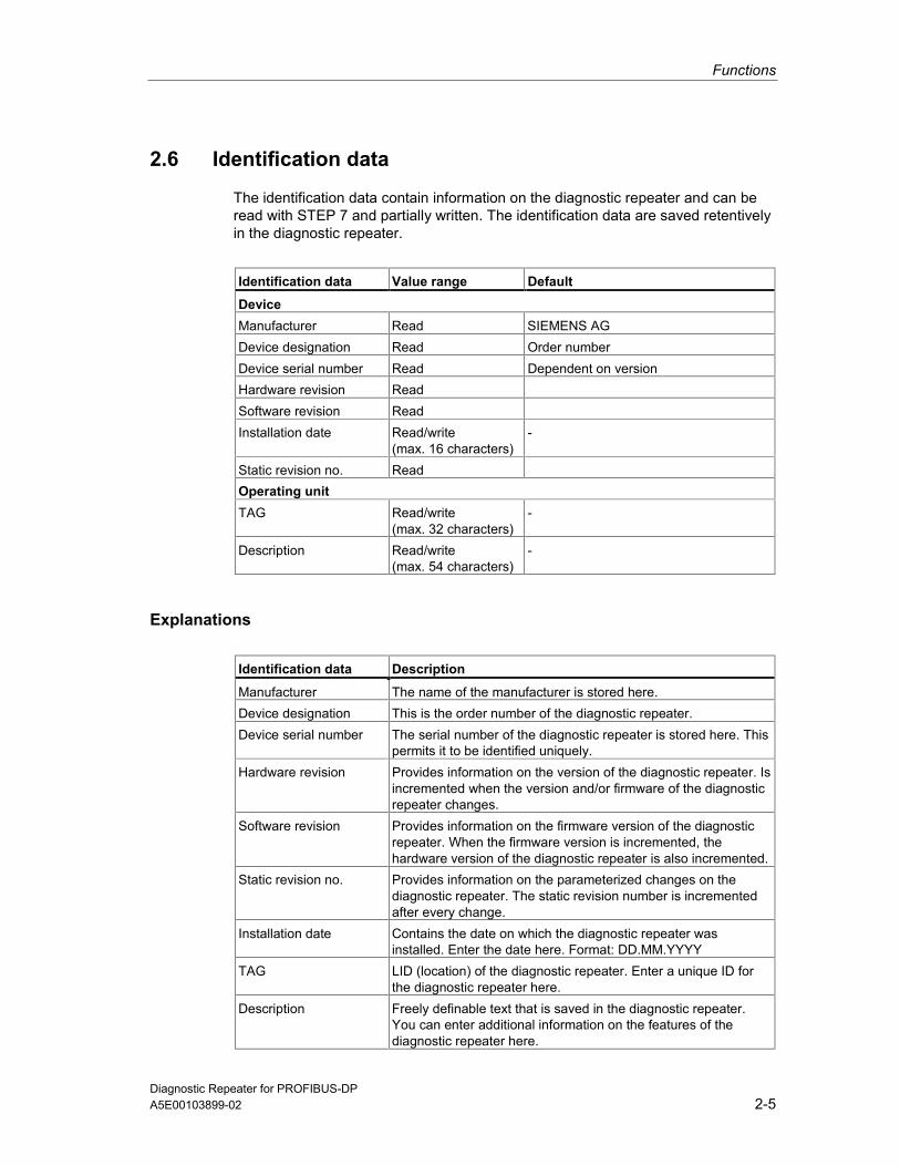
2.6 Identification data
The identification data contain information on the diagnostic repeater and can beread with STEP 7 and partially written. The identification data are saved retentivelyin the diagnostic repeater.
Identification data Value range Default
DeviceManufacturer Read SIEMENS AGDevice designation Read Order numberDevice serial number Read Dependent on versionHardware revision ReadSoftware revision ReadInstallation date Read/write
(max. 16 characters)-
Static revision no. ReadOperating unitTAG Read/write
(max. 32 characters)-
Description Read/write(max. 54 characters)
-
Explanations
Identification data Description
Manufacturer The name of the manufacturer is stored here.Device designation This is the order number of the diagnostic repeater.Device serial number The serial number of the diagnostic repeater is stored here. This
permits it to be identified uniquely.Hardware revision Provides information on the version of the diagnostic repeater. Is
incremented when the version and/or firmware of the diagnosticrepeater changes.
Software revision Provides information on the firmware version of the diagnosticrepeater. When the firmware version is incremented, thehardware version of the diagnostic repeater is also incremented.
Static revision no. Provides information on the parameterized changes on thediagnostic repeater. The static revision number is incrementedafter every change.
Installation date Contains the date on which the diagnostic repeater wasinstalled. Enter the date here. Format: DD.MM.YYYY
TAG LID (location) of the diagnostic repeater. Enter a unique ID forthe diagnostic repeater here.
Description Freely definable text that is saved in the diagnostic repeater.You can enter additional information on the features of thediagnostic repeater here.

Functions
Diagnostic Repeater for PROFIBUS-DP2-6 A5E00103899-02
2.7 Monitoring functions for the clocked PROFIBUS bussystem
Features of the clocked PROFIBUS bus systemReproducible response times (e.g. of the same length) are achieved in SIMATICwith an equidistant DP bus cycle and the synchronization of the following free-running individual cycles:
• Free-running cycle of the user program. The length of the cycle time can varyon the basis of acyclic program branching.
• Free-running, variable DP cycle on the PROFIBUS subnet
• Free-running cycle on the DP slave backplane bus.
• Free-running cycle at signal conditioning and conversion in the electronicmodules of the DP slaves.
All the affected cycles run with equidistance and clock synchronization. Theprocess response times thus have the same length and are shorter because of thelack of cycle jumps.
Monitoring functions of the diagnostic repeaterThe diagnostic repeater offers functions for detecting errors in an equidistance DPbus cycle and reporting them to the associated DP master.
The following errors are detected:
• Violation of the equidistant DP cycle (TDP)
• Violation of the time TDX (cyclic part of the equidistant DP cycle)
TDX monitoring establishes whether or not the I/O data have been received withthe "expected" time in relation to the beginning of the current cycle.
The violation of the time TDX can only be detected if the diagnostic repeater ishandled as the last node in the cyclic part of the equidistant DP cycle of the DPmaster.
You achieve this by:
• Assigning the diagnostic repeater the highest node address in the DP mastersystem and
• Using a DP master system in which the nodes are always processed in thesame order.
To find out whether the DP master system used does this, refer to thecorresponding technical specifications.
Functions
Diagnostic Repeater for PROFIBUS-DPA5E00103899-02 2-7
Monitoring function dataThe diagnostic repeater can monitor an equidistant DP bus cycle (TDP) from 1 msto 32 ms.
The diagnostic repeater is synchronized with the current, equidistant DP bus cycleafter 150 cycles. Diagnostic messages about equidistance violations are thusavoided in the startup phase.
The diagnostic repeater monitors the set or determined equidistant DP bus cyclewith a tolerance range of ±2 µs and the time TDX with a tolerance range of ±10 µs.
Prerequisites• As of STEP 7 V5.1 with Service Pack 3
• The equidistance master must be a DP master class 1 (i.e. a programmingdevice/PC cannot be an equidistance master).
• In equidistance mode only one DP master (class 1) can be active on thePROFIBUS-DP. Programming devices/PCs (class 2) can be connectedadditionally.

Functions
Diagnostic Repeater for PROFIBUS-DP2-8 A5E00103899-02
Diagnostic Repeater for PROFIBUS-DPA5E00103899-02 3-1
3 Configuration Options
3.1 Design guidelines for diagnostic repeaters
3.1.1 PROFIBUS networks
Design guidelines for PROFIBUS networksWhen designing a PROFIBUS network with diagnostic repeaters the designguidelines and the information given in the manual SIMATIC NET PROFIBUSNetworks (Order No. 6GK1970-5CA20-0AA1) apply.
MPI networksLine diagnostics are not possible in pure MPI networks.
Mixed copper and fiber-optic cable networksIf it is possible to do without the full functionality (diagnostic functionality) of thediagnostic repeater, diagnostic repeaters can be used in mixed copper and fiber-optic cable networks.
PROFIBUS FDL/FMS networksLine diagnostics are in principle possible in PROFIBUS FDL/FMS networks. Undersome circumstances, however, nodes may not be detected or they may besubjected to interference during topology determination. Topology determinationshould therefore not be carried out in PROFIBUS FDL/FMS networks. Thediagnostic repeater used must not contain any topology data.
Diagnostic information can only be displayed through direct access to thediagnostic repeater from STEP 7 or COM PROFIBUS.

Configuration Options
Diagnostic Repeater for PROFIBUS-DP3-2 A5E00103899-02
3.1.2 PROFIBUS components
RS 485 bus terminalThe RS 485 bus terminal must not be used together with the diagnostic repeater.
Lightning protection elementsThe diagnostic repeater can be used with the lightning protection elementsapproved for the PROFIBUS-DP.
Isolating transformerThe diagnostic repeater may only be used at the non-intrinsically-safe end of anisolating terminator.
The same limitations apply to the isolating terminator as for components withrepeater function.
ET 200UThe ET 200U module is not detected during topology determination. Inother words, it is not displayed in diagnostic messages in STEP 7 or COMPROFIBUS and is shown in the topology display as a node that cannot beassigned. Nevertheless, line diagnostics are still possible on the correspondingsegment without restrictions.

Configuration Options
Diagnostic Repeater for PROFIBUS-DPA5E00103899-02 3-3
3.1.3 Bus connectors and cables
PROFIBUS-DP bus connectorsSee the list of permissible PROFIBUS-DP bus connectors in Appendix A.
Requirements to be met by bus connectorsIf you use other connectors, the design guidelines for the diagnostic repeaterrequire bus connectors with integrated series inductance in accordance with IEC61158:Ed3 Type 3:
• Inductance (L1 to L4): 110 nH ±20 %
• Resistor between A and A’, as well as between B and B’: ≤ 0.35 Ohm
RxD / TxD-N
RxD / TxD-P
L3
L2L1
L4
o
oo
o
oo
PROFIBUS-Leitung
A A’
B B’PROFIBUS-Leitung

Configuration Options
Diagnostic Repeater for PROFIBUS-DP3-4 A5E00103899-02
SIMATIC NET PROFIBUS cablesSee Appendix A for a list of permissible SIMATIC NET PROFIBUS cables.
Requirements to be met by cables
NoteIf you are using cables that are not designed for the Fast Connect connectionsystem, you will have to convert to FastConnect cables.
If you are using other cables, the design guidelines for the diagnostic repeaterrequire them to comply with the technical specifications in the table below:
Technical specifications Values
AttenuationAt 16 MHzAt 4 MHzAt 38.4 kHzAt 9.6 kHz
< 42 dB/km< 22 dB/km< 4 dB/km< 2.5 dB/km
Characteristic impedanceAt 3 to 20 MHzAt 38.4 kHzAt 9.6 kHz
150 ± 15 Ω185 ± 18.5 Ω270 ± 27 Ω
Rated value 150 Ω Loop resistance ≤ 110 Ω/km Shield resistance ≤ 9.5 Ω/km Working capacity Approx. 28.5 nF/km
If you are using a cable that does not comply with the specifications in the table,get in touch with your SIEMENS contact.

Configuration Options
Diagnostic Repeater for PROFIBUS-DPA5E00103899-02 3-5
3.1.4 Line length and cascading depth
Maximum monitorable line lengthIf you are using standard cables, at baud rates of 9.6 kbps to 12 Mbps thediagnostic repeater can monitor a maximum of 100 m of cable per segment (DP2,DP3).
The monitorable line length of some cable types is limited (see Appendix A).
Cascading depthUp to nine diagnostic repeaters can be connected in series.
A diagnostic message is produced if more than nine diagnostic repeaters areconnected in series.
DRDR
DR
DRDR
DR
1 2 3 7 8 9...

Configuration Options
Diagnostic Repeater for PROFIBUS-DP3-6 A5E00103899-02
3.1.5 Spur lines
Spur lines, including those within devices, are not permissible. The party line of theS7-300 corresponds, for example, to an internal device spur line with a length of upto 0.6 m.
CautionSpur lines are not allowed at segments DP2 and DP3 of diagnostic repeaters sincethey prevent correct determination of the topology and fault points.
Avoiding spur linesSpur lines arise, for example, when programming devices or nodes are connectedas a branching or when PROFIBUS if connectors are stacked over each other.Methods of avoiding spur lines:
• Connect the programming devices directly to the programming device interfaceof the diagnostic repeater or
• To connect programming devices, use only the SIMATIC S5/S7 spur line for 12Mbps ("active cable").
• The RS 485 bus terminal may not be used.
Arrangement of the nodes without spur linesThe following example shows an illegal arrangement since Node 14 is connectedvia a spur line, for example by stacking two connectors over each other.
xDR 1311 12
14
Configuration Options
Diagnostic Repeater for PROFIBUS-DPA5E00103899-02 3-7
3.1.6 Only one measuring circuit at a segment
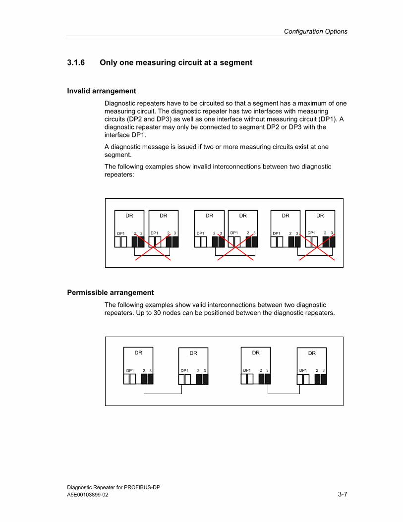
Invalid arrangementDiagnostic repeaters have to be circuited so that a segment has a maximum of onemeasuring circuit. The diagnostic repeater has two interfaces with measuringcircuits (DP2 and DP3) as well as one interface without measuring circuit (DP1). Adiagnostic repeater may only be connected to segment DP2 or DP3 with theinterface DP1.
A diagnostic message is issued if two or more measuring circuits exist at onesegment.
The following examples show invalid interconnections between two diagnosticrepeaters:
DR
DP1 2 3
DR
DP1 2 3
DR
DP1 2 3
DR DR
DP1 2 3 DP1 2 3
DR
DP1 2 3
Permissible arrangementThe following examples show valid interconnections between two diagnosticrepeaters. Up to 30 nodes can be positioned between the diagnostic repeaters.
DR DR
DP1 2 3 DP1 2 3
DR DR
DP1 2 3 DP1 2 3
Configuration Options
Diagnostic Repeater for PROFIBUS-DP3-8 A5E00103899-02
3.1.7 Arrangement of the DP master
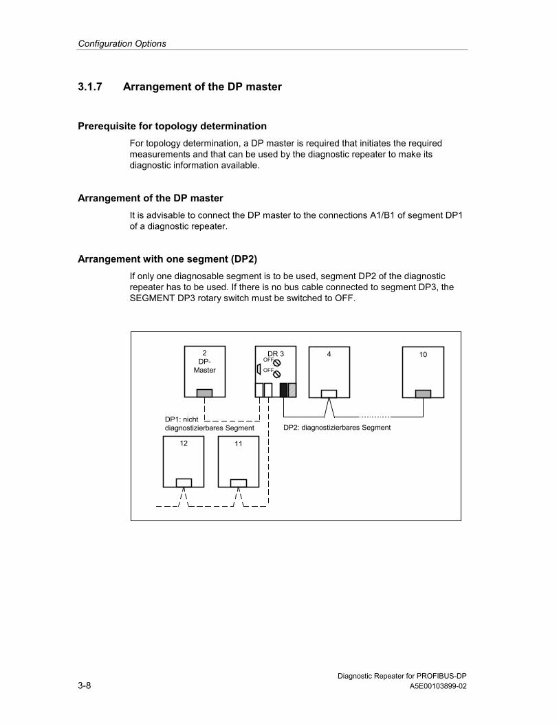
Prerequisite for topology determinationFor topology determination, a DP master is required that initiates the requiredmeasurements and that can be used by the diagnostic repeater to make itsdiagnostic information available.
Arrangement of the DP masterIt is advisable to connect the DP master to the connections A1/B1 of segment DP1of a diagnostic repeater.
Arrangement with one segment (DP2)If only one diagnosable segment is to be used, segment DP2 of the diagnosticrepeater has to be used. If there is no bus cable connected to segment DP3, theSEGMENT DP3 rotary switch must be switched to OFF.
4 10
12 11
2DP-
Master
DR 3
OFF
OFF
DP1: nichtdiagnostizierbares Segment DP2: diagnostizierbares Segment

Configuration Options
Diagnostic Repeater for PROFIBUS-DPA5E00103899-02 3-9
Arrangement with two segments (DP2 and DP3)If a bus line is connected to segment DP3, the turn switch SEGMENT DP3 has tobe set to ON.
If no outgoing bus cable is connected to A1’/B1’ connections of segment DP1, theTERMINATOR DP1 rotary switch must be switched to ON. This activates theterminator for segment DP1 and de-activates the connections A1’/B1’.
4 10
11 12
2DP
master
DR 3
ON
ON
DP1: non-diagnostics-capable segment,terminating resistor connected
DP3: diagnostics-capable segment
DP2: diagnostics-capable segment

Configuration Options
Diagnostic Repeater for PROFIBUS-DP3-10 A5E00103899-02
3.1.8 Example configuration
Example configuration
2DP
master
3
7
25
5
31
32 33
41 43
34
DR 4
OFFON
DR 12
ON
OFF
DR 40
ON
ON
DR 24
ON
ON
DR 22
OFFON
DR 6
ON
ONPG 0
23
42
Configuration Options
Diagnostic Repeater for PROFIBUS-DPA5E00103899-02 3-11
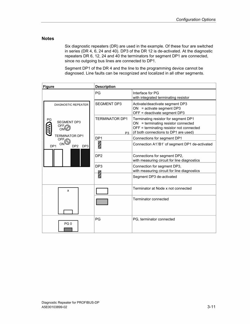
NotesSix diagnostic repeaters (DR) are used in the example. Of these four are switchedin series (DR 4, 6, 24 and 40). DP3 of the DR 12 is de-activated. At the diagnosticrepeaters DR 6, 12, 24 and 40 the terminators for segment DP1 are connected,since no outgoing bus lines are connected to DP1.
Segment DP1 of the DR 4 and the line to the programming device cannot bediagnosed. Line faults can be recognized and localized in all other segments.
Figure Description
PG Interface for PGwith integrated terminating resistor
SEGMENT DP3 Activate/deactivate segment DP3ON = activate segment DP3OFF = deactivate segment DP3
TERMINATOR DP1 Terminating resistor for segment DP1ON = terminating resistor connectedOFF = terminating resistor not connected(if both connections to DP1 are used)
DP1 Connections for segment DP1Connection A1’/B1’ of segment DP1 de-activated
DP2 Connections for segment DP2,with measuring circuit for line diagnostics
DP3 Connection for segment DP3,with measuring circuit for line diagnostics
SEGMENT DP3
DIAGNOSTIC REPEATER
DP3DP2DP1
TERMINATOR DP1
OFFON
OFFON
PG
Segment DP3 de-activated
Terminator at Node x not connectedx
Terminator connected
PG 0PG PG, terminator connected
P3

Configuration Options
Diagnostic Repeater for PROFIBUS-DP3-12 A5E00103899-02
3.2 Limitations when using components with repeaterfunction
NoteComponents with repeater function can be used if partially faulty determination ofthe topology is acceptable and if it is possible to do without line diagnostics afterthe component with repeater function.
RuleComponents with a repeater function can be used:
• Without limitations in segment DP1 and at the end of segments DP2 and DP3of a diagnostic repeater
• In segments DP2 and DP3, when topology determination with some errors isacceptable and it is possible to do without line diagnostics in the correspondingsegment after the component with a repeater function.
PROFIBUS components with a repeater functionThe following PROFIBUS components can be used, for example, in connectionwith the diagnostic repeater:
• RS 485 repeater
• Optical Link Module (OLM),
• Optical Bus Terminal (OBT),
• Infrared Link Module (ILM),
• Power Rail Booster,
• Data photoelectric barriers via PROFIBUS-DP.

Configuration Options
Diagnostic Repeater for PROFIBUS-DPA5E00103899-02 3-13
ExplanationThe line diagnostic only functions up to the component with repeater function.Every downstream node is indicated with the distance of the component withrepeater function.
Consequences:
• The nodes are entered with incorrect specification of the distance in thetopology table.
• The relative specification of the error can possibly not be indicated correctly.
• All the nodes lying before and after the component with repeater function arecounted as nodes of one PROFIBUS-DP segment. This can lead to the errormessage "More than 32 nodes connected to a measuring segment". This errormessage can be suppressed by de-activating the determination of the topologyfor this segment in the configuration of the diagnostic repeater.
Components with integrated section monitoring
CautionComponents with integrated section monitoring, such as the Optical Link Module(OLM), can lead to segments being broken and thus to bus faults and interruptionswhile the topology is being determined.
Deactivate the determination of the topology for that segment of the diagnosticrepeater to which components with integrated section monitoring are connected(see Section 6.3.2).

Configuration Options
Diagnostic Repeater for PROFIBUS-DP3-14 A5E00103899-02
Network design with component with repeater functionThe following example shows a possible network design with a component withrepeater function (R).
DR 4
OFF
OFF5
R
76 8
5 m
12 m
25 m20 m
30 m
PROFIBUS segment:max. 32 nodes PROFIBUS segment: max. 32 nodes
The component with a repeater function is not detected as a node (no PROFIBUSaddress of its own) and is thus not listed in the topology table.
The diagnostic repeater 4 determines the following data for segment DP2:
PROFIBUS address Distance fromdiagnostic repeater 4
Topology determination
5 5 m Correct6 12 m ! Faulty7 12 m ! Faulty8 12 m ! Faulty

Configuration Options
Diagnostic Repeater for PROFIBUS-DPA5E00103899-02 3-15
3.2.1 Network design with an RS 485 repeater
Possible network design
DR 4
OFF
OFF5 6 7 8
1210 11
F1
F2
F3
7 m
14 m18 m
30 m
30 m
20 m
16 15 14
40 m
?
?
?
?
25 m
DR 13
ON
ONRS485

Configuration Options
Diagnostic Repeater for PROFIBUS-DP3-16 A5E00103899-02
Topology table diagnostic repeater 4The diagnostic repeater 4 determines the following data:
PROFIBUS address Distance fromdiagnostic repeater 4
Topology determination
5 7 m Correct6 14 m Correct7 25 m Correct8 30 m Correct10 18 m ! Faulty11 18 m ! Faulty12 18 m ! FaultyDR 13 18 m ! Faulty
Explanation• Nodes 10, 11, 12 and DR 13 are assigned to segment DP2 of the diagnostic
repeater DR 4.
• Nodes 10, 11, 12 and DR 13 are all indicated at the distance of the RS 485repeaters (18 m).
• Error F1 is recognized and specified with the absolute distance to the DR 4(16 m), but specified between Nodes 6 and 10.
Topology table diagnostic repeater 13The diagnostic repeater 13 determines the following data:
PROFIBUS address Distance fromdiagnostic repeater 13
Topology determination
14 20 m Correct15 30 m Correct16 40 m Correct
Explanation• Error F2 is not recognized since it occurred at segment DP1 of the DR 13
which cannot be diagnosed.
• Error F3 is recognized and specified correctly between Nodes 14 and 15.
• Errors occurring at segment DP3 of DR 13 are recognized correctly andlocated correctly.

Configuration Options
Diagnostic Repeater for PROFIBUS-DPA5E00103899-02 3-17
3.2.2 Network design with an Optical Link Module (OLM)
Possible network designIf you use an Optical Link Module (OLM) with integrated section monitoring in yourplant, you must de-activate the determination of the topology for segment (DP2) ofthe diagnostic repeater (DR 4) to which the module is connected.
DR 4
OFF
OFF5 6 7 8
7 m14 m
18 m
30 m
25 m
OLM
OLM
11
F3
30 m
20 m
15 14 13
40 m
DR 12
ON
ON
F2
F1

Configuration Options
Diagnostic Repeater for PROFIBUS-DP3-18 A5E00103899-02
Topology table diagnostic repeater 4The topology determination function of the diagnostic repeater 4 has to be de-activated for segment DP2 by means of the configuration (see Section 6.3.2). Nodata are determined.
CautionComponents with integrated section monitoring, such as the Optical Link Module(OLM), can lead to segments being broken and thus to bus faults and interruptionswhile the topology is being determined.
Explanation• The topology cannot be determined for segment DP2 due to the connected
Optical Link Module.
• Nodes 11 and DR 12 are assigned to segment DP2 of the diagnostic repeaterDR 4.
• Error F1 is recognized and specified with the absolute distance to thediagnostic repeater DR 4 (16 m).
Topology table diagnostic repeater 12The diagnostic repeater 12 determines the following data for segment DP2:
PROFIBUS address Distance fromdiagnostic repeater 12
Topology determination
13 20 m Correct14 30 m Correct15 40 m Correct
Explanation• The topology can be determined correctly for segments DP2 and DP3.
• Error F2 is not recognized since it occurred at segment DP1 of the DR 12which cannot be diagnosed.
• Error F3 is recognized and specified correctly between Nodes 13 and 14.
• Errors occurring at segment DP3 of DR 12 are recognized correctly andlocated correctly.

Configuration Options
Diagnostic Repeater for PROFIBUS-DPA5E00103899-02 3-19
3.3 Recommendations for structuring a new plant
Multiple-stage diagnostic conceptA multiple-stage diagnostic concept allows monitoring of a PROFIBUS networkduring every plant phase. It provides for the following procedure for structuring andoperating a new plant:
• Installation: avoiding errors in the physical structure of the bus by using theFast Connect system
• Installation/commissioning: checking the physical structure of the bus withthe BT 200 test device in offline mode
• Current operation: line diagnostics through the use of the diagnostic repeater
Fast Connect systemPROFIBUS Fast Connect is a system for preparing copper PROFIBUS cablesquickly and easily.
The system consists of three components suited to each other:
• Fast Connect bus lines for rapid mounting,
• Fast Connect Stripping Tool,
• Fast Connect bus connector for PROFIBUS (with insulation piercing).
PROFIBUS test device BT 200During the installation phase the test device BT 200 can be used to check thePROFIBUS line even when the nodes are plugged. Installation errors are foundand logged rapidly. The person installing does not require any special PROFIBUSknowledge.
The test device BT 200 can check the following points:
• Wire break, shield break, missing or too many terminators,
• Short circuit (A to B, A/B to shield),
• Reflection points which cause faults,
• Interchanged signal lines A/B,
• Specification of the length of the laid line,
• Availability of the slaves,
• PROFIBUS interface of the nodes.

Configuration Options
Diagnostic Repeater for PROFIBUS-DP3-20 A5E00103899-02
3.4 Use in an existing plant
Points to be observed when extending an existing plantIf you want to add diagnostic repeaters to an existing plant, you must:
• Observe the design guidelines for the diagnostic repeater,
• Use a programming device/PC with STEP 7 or COM PROFIBUS or an S7 CPUwith the integrated system function SFC 103 "DP_TOPOL", in order to be ableto carry out topology determination,
• Re-configure the DP master used in order to include the diagnostic repeater asa new DP slave and in order to be able to access the diagnostic information ofthe diagnostic repeater.
Points to be observed when replacing a diagnostic repeaterYou only receive correct diagnostic messages and distance specifications if youdetermine the topology after replacing a diagnostic repeater. Otherwise theinformation provided will be incorrect or incomplete.
Using a brand-new diagnostic repeater
The topology table of a brand-new diagnostic repeater is empty at first. In otherwords, the diagnostic repeater can only supply the distance of a fault location inabsolute terms (e.g. the fault location is 30 meters from the diagnostic repeater).
Using a diagnostic repeater that has already been used
The topology table of a diagnostic repeater that has already been used containsinformation on the plant from which it has been taken.This means that the diagnostic repeater can specify the distance to a fault pointabsolutely and relatively. However, as a rule this information is not suitable for thenew plant.
Changes to plantsThe topology must always be determined when a plant is changed, meaning whenyou
• Add nodes,
• Exchange nodes,
• Remove nodes,
• Change PROFIBUS addresses,
• Change the line length.

Diagnostic Repeater for PROFIBUS-DPA5E00103899-02 4-1
4 Installation
4.1 Mounting rules
Mounting dimensionsInstallation height: 125 mm
Installation width: 80 mm
Installation depth without rail: 66.3 mm
Installation depth with rail: 72.2 mm
Mounting positionPermissible mounting positions are horizontal and vertical mounting on a verticallevel.
Mounting railThe diagnostic repeater can be mounted on the following mounting rails:
• Mounting rail for S7-300 or
• DIN rail conforming to EN 50022 (35 x 15 mm)
Required toolScrew driver 4 mm
PrerequisitesThe mounting rail is mounted.

Installation
Diagnostic Repeater for PROFIBUS-DP4-2 A5E00103899-02
4.2 Mounting the diagnostic repeater on a mounting rail forS7-300
In order to mount the diagnostic repeater on a mounting rail for S7-300, the slideon the rear of the diagnostic repeater has to be removed.
1. Insert a screwdriver under the shoulder of the latch element (1) and
2. Move the screwdriver to the module rear.Keep this position!Result: The slide is unlatched from the diagnostic repeater.
3. Use the free hand to move the slide (2) upwards until the stop position andremove the slide.Result: The slide is removed from the diagnostic repeater.
4. Hang the diagnostic repeater into the mounting rail for S7-300 (3).
5. Swivel it backwards until the stop (4) is reached.
6. Screw the two fixing screws fast with a torque of 80 to 110 Ncm (5).
1
2
5 4
3
Dismantling the diagnostic repeater from the mounting rail for S7-300In order to dismantle the diagnostic repeater from the mounting rail:
1. Loosen the fixing screw of the diagnostic repeater and
2. Swing the diagnostic repeater upwards and out.

Installation
Diagnostic Repeater for PROFIBUS-DPA5E00103899-02 4-3
4.3 Mounting the diagnostic repeater on a DIN rail
Mounting the diagnostic repeater on a DIN railIn order to mount the diagnostic repeater on a DIN rail the slide must be positionedon the rear of the diagnostic repeater.
1. Hang the diagnostic repeater into the DIN rail and
2. Swivel it backwards until the slide latches in.
Dismantling the diagnostic repeater from the DIN railIn order to dismantle the diagnostic repeater from the DIN rail:
3. Use a screwdriver to press the slide at the bottom of the diagnostic repeaterdownwards and
4. Swing the diagnostic repeater upwards and out of the DIN rail.
2
1

Installation
Diagnostic Repeater for PROFIBUS-DP4-4 A5E00103899-02

Diagnostic Repeater for PROFIBUS-DPA5E00103899-02 5-1
5 Wiring
5.1 Basis
PrerequisitesThe diagnostic repeater is mounted on the mounting rail.
Particular points when wiringAll the lines are connected from below. The bus cables are connected by means ofan insulation piercing technique (Fast Connect connection system). The insulationpiercing connecting devices are designed for 10 connecting cycles.
NoteInsulation residues can remain in the insulation piercing connecting device duringopening.This can cause problems during the next connection process.Therefore ensure that no insulation residues remain when you withdraw the linewhile opening the insulation piercing connecting device.
Required tool• Use, for example, the Fast Connect stripping tool (order no. 6GK1905-6AA00)
• Screw driver 4 mm.

Wiring
Diagnostic Repeater for PROFIBUS-DP5-2 A5E00103899-02
5.2 Connecting the supply voltage
Cable typesThe following cables can be used to connect the 24 V DC supply cables:
• Rigid cable: 0.14 mm2 to 2.5 mm2
• Flexible cable with wire end ferrule: 0.25 mm2 to 1.5 mm2
• Flexible cable without wire end ferrule from 0.14 mm2 to 2.5 mm2
Connecting the power supplyConnect the power supply of the diagnostic repeater as follows:
1. Bare the cable for the 24 V DC supply voltage.
2. Connect the cable to the terminals "PE", "M" and "L+".
The terminal M5.2 of the power supply is the groundreference for external signal messages.This terminal may not be wired.

Wiring
Diagnostic Repeater for PROFIBUS-DPA5E00103899-02 5-3
5.3 Connecting the PROFIBUS cables
Prerequisites: bus connectors and cablesNote the requirements placed on the bus connectors and cables that you use inyour plant with the diagnostic repeater (see Section 3.1.3).
Overview of the procedure• Connecting the PROFIBUS cables
• Connecting or disconnecting the terminator DP1
• Connecting or disconnecting segment DP3
Connecting the PROFIBUS cablesConnect the PROFIBUS cable to the diagnostic repeater as follows:
1. Cut the PROFIBUS cable to the required length.
2. Bare the PROFIBUS cable in accordance with the figure.
3. Screw open the black strain relief.
4. Open the transparent contacting cover for the insulation piercing connectingdevice.
5. Insert the incoming cable of segment DP1 into the contacting cover A1/B1, theoutgoing cable into the contacting cover A1’/B1’. Insert the outgoing cables ofsegments DP2 and DP3 into the contacting cover A2/B2 and A3/B3. Terminatered to red and green to green.
6. Press the contacting cover firmly downwards.
7. Screw the black strain relief closed.
Stripping
7,5+1
15+/-2FC stripping tool: 6GK1905-6AA00

Wiring
Diagnostic Repeater for PROFIBUS-DP5-4 A5E00103899-02
Connections• Connection A1/B1 for the feeding bus line of segment DP1
• Connection A1/B1 for the outgoing bus line of segment DP1
• Connection A2/B2 for the bus cable of segment DP2
• Connection A3/B3 for the bus cable of segment DP3
• Connections for the power supply
DP3A3/B3
DP2A2/B2
DP1A1/B1 A1´/B1´
Connecting/disconnecting TERMINATOR DP1If no outgoing bus cable is connected to the connections A1’/B1’ of segment DP1,set the turn screw TERMINATOR DP1 to ON on the diagnostic repeater.
Connecting/disconnecting SEGMENT DP3If no bus cable is connected to segment DP3, set the turn switch SEGMENT DP3to OFF on the diagnostic repeater.

Wiring
Diagnostic Repeater for PROFIBUS-DPA5E00103899-02 5-5
5.4 Block diagram of the diagnostic repeater
Block diagram
SegmentDP2
SegmentDP3
RS-485
SegmentDP1
Logic
L+
MDC 24V
Electricalisolation
Electricalisolation
M5.2
PE
Measuringcircuit
M5.2
P5.2
M5.1
P5.1
RS-485
R
ONOFF
1 MOhm1 MOhm
10 MOhm
PG socket
A1/B1 A1’/B1’
Measuringcircuit
Power supply

Wiring
Diagnostic Repeater for PROFIBUS-DP5-6 A5E00103899-02
Control-to-load isolation• Segment DP1 which cannot be diagnosed is isolated from segments DP2, DP3
which can be diagnosed and from the programming-device interface
• The power supply is isolated.
• Segments DP2, DP3 and the programming-device interface are non-isolated toeach other.
Earth-free operationEarth-free operation means that the ground and the PE are not connected to eachother.
Earth-free operation of the diagnostic repeater means that bus segments can beoperated isolated.
Designing a diagnostic repeater earth-freeIn order to ensure earth-free operation of the diagnostic repeater you have toensure earth-free power supply of the diagnostic repeater.
The PE terminal must always be connected.
Programming device connection of the diagnostic repeaterThe programming device connection is only available for one node (programmingdevice or OP) and is not designed for networking. The terminating resistor is firmlyintegrated in the programming device interface of the diagnostic repeater.
When using cables with bus connectors you should therefore switch theterminating resistor on the diagnostic repeater side to OFF and on theprogramming device/OP side, as usual, to ON.
Pin assignment of the cannon connector (PG socket)
View Pin No. Signal name Designation
1 - -2 M24 V Ground 24 V3 RxD/TxD-P Data line B4 RTS Request to Send5 M5V2 Data reference potential (from node)6 P5V2 Supply plus (from node)7 P24V 24 V8 RxD/TxD-N Data line A
2
4
1
5
37
9
6
8
9 - -

Diagnostic Repeater for PROFIBUS-DPA5E00103899-02 6-1
6 Commissioning
6.1 Addressing
PrerequisitesThe diagnostic repeater is designed as a DP slave and therefore has its ownPROFIBUS address. This specifies under which address the diagnostic repeater isaddressed at the PROFIBUS-DP.
• The PROFIBUS address is set by means of switches. They are positioned onthe front of the diagnostic repeater, protected by a hinged window.
• The PROFIBUS addresses 1 to 125 are permitted.
• Each address may only be assigned once at the PROFIBUS-DP.
NoteThe LEDs SF, BF and DR flash if the illegal PROFIBUS addresses 0, 126 and 127are set.
Required ToolScrew driver 4 mm

Commissioning
Diagnostic Repeater for PROFIBUS-DP6-2 A5E00103899-02
Setting a PROFIBUS addressThe PROFIBUS address results from the addition of the numbers which areassigned to the switches.
1. Swivel open the window at the diagnostic repeater.
2. Use the switches to set the desired PROFIBUS address.
3. Close the window.
The switches are activated if they are pressed to the left.The example has the PROFIBUS address:64 + 16 + 8 + 2 = 90.
Changing the PROFIBUS addressYou can change the set PROFIBUS address at any time. The diagnostic repeatertakes over the modified PROFIBUS address after the 24 V DC supply has beenswitched off and on.

Commissioning
Diagnostic Repeater for PROFIBUS-DPA5E00103899-02 6-3
6.2 Configuration
PrerequisitesThe diagnostic repeater is configured with STEP 7 or COM PROFIBUS.
The diagnostic repeater is connected to the DP master system as a DP slave.
• STEP 7
As of STEP 7 V5.1 with Service Pack 2, the diagnostic repeater appears in thehardware catalog of STEP 7 under PROFIBUS-DP / Network Components /Diagnostic Repeaters.In older versions of STEP 7, the diagnostic repeater is integrated via the DDB file.In this case, it appears in the hardware catalog under PROFIBUS-DP / AdditionalField Devices / General.
• COM PROFIBUS
As of COM PROFIBUS V5.1 with Service Pack 2, the repeater appears underDP slave / General / Network Components / Diagnostic Repeaters.In older versions of COM PROFIBUS, the diagnostic repeater is integrated via theDDB file.
Available functions with STEP 7
Diagnostic repeater 6ES7972-0AB00-0XA0 6ES7972-0AB01-0XA0 STEP 7 STEP 7 Functions <V5.1 SP1 V5.1 SP2 >V5.2 <V5.1 SP1 V5.1 SP2 >V5.2Topology determination - x x - x xGraphical diagnostic display - x x - x xText-based diagnostic display x x x x x xDisplay of topology,diagnostic buffer, statistics
- - - - - x
Identification data - - - - - xMonitoring function for theclocked PROFIBUS bus system
- - - - - x
Firmware update - - - - - x
Available functions with COM PROFIBUS
Diagnostic repeater 6ES7972-0AB00-0XA0 6ES7972-0AB01-0XA0
COM PROFIBUS COM PROFIBUS Functions <V5.1 SP1 V5.1 SP2 <V5.1 SP1 V5.1 SP2Topology determination - x - xGraphical diagnostic display - x - xText-based diagnostic display x x x x

Commissioning
Diagnostic Repeater for PROFIBUS-DP6-4 A5E00103899-02
Diagnostic repeater 6ES7972-0AB00-0XA0 6ES7972-0AB01-0XA0
Display of topology,diagnostic buffer, statistics
- - - -
Identification data - - - -Monitoring function for theclocked PROFIBUS bus system
- - - -
Firmware update - - - -
Downloading Service Pack 2 for COM PROFIBUS V5.1The COM PROFIBUS version for the diagnostic repeater can be found in theInternet under
http://www4.ad.siemens.de/view/cs/de/7256370
DDB file for non-Siemens masterThe diagnostic repeater is configured via the GSD file. The Siemens GSD can befound in the Internet under
http://www.ad.siemens.de/csi/gsd
Topology determination is not possible with non-Siemens masters. Line faults aredisplayed as text rather than graphically.
6.2.1 Configuration for standard operation
Configuration• STEP 7
In STEP 7 the "DR-CfgData" module is entered in the configuration tableautomatically.
• COM PROFIBUS
Drag the "DR-CfgData" module from the hardware catalog to the configurationtable.

Commissioning
Diagnostic Repeater for PROFIBUS-DPA5E00103899-02 6-5
6.2.2 Configuring the monitoring functions for the clocked PROFIBUSbus system
Configuration• STEP 7
Drag the TSYNC diagnostic module from the hardware catalog to the configurationtable.
This allows you to detect, in addition to the diagnostic data in the input data of thediagnostic repeater, TDX violations and/or TDP violations, including the associatedcycle. The structure of the input data is identical to that of the diagnostic message(see Chapter 7.2.7).
• COM PROFIBUS
Monitoring functions for the clocked PROFIBUS bus system are not available.
Procedure for setting clock synchronization (equidistance)1. Settings on the CPU:
• Set a CPU clocked interrupt ("Clocked Interrupts" tab)
• Select the DP master system used.
• Select the desired process image partition.
2. Settings on the DP master system:
• Activate equidistance on the DP master system ("General" tab > Properties >"Network Settings" tab > Options)
• Set the length of the equidistant DP cycle (min. 1 ms, max. 32 ms)
3. Settings on the diagnostic repeater:
• Activate "Synchronize DP slave with DP cycle".
• Enter the times Ti and To (unless "Times Ti and To same for all slaves" is seton the DP master system).Recommendation: Accept the defaults for Ti and To.

Commissioning
Diagnostic Repeater for PROFIBUS-DP6-6 A5E00103899-02
6.3 Parameter assignment with STEP 7
PrerequisitesIf you are using a SIMATIC S7 DP master from Siemens and you comply with thedesign guidelines of the diagnostic repeater (see Section 3.1), you do not have toassign any parameters.
It is possible that you may have to parameterize the diagnostic message framelength if you are not using a SIMATIC S7 DP master.
If you use components with repeater function, you may have to de-activate thetopology determination function of the diagnostic repeater.
6.3.1 Parameterizing the diagnostic message frame length
Some DP masters are limited with regard to the diagnostic message frame length.The diagnostic display may therefore not be possible for all segments. Check thesupported diagnostic message frame length on the basis of the technical data ofthe DP master and, if necessary, change the parameter configuration of thediagnostic repeater.
Set the parameter to the value which the used DP master can fulfill in the"Properties - DP slave" dialog box.
Parameters Value Byte
Diagnostic message framelength for
Segment DP2, DP3, DP1, PG, TSYNCSegment DP2, DP3, DP1, PGSegment DP2, DP3, DP1Segment DP2, DP3Segment DP2
9184 (default)654627

Commissioning
Diagnostic Repeater for PROFIBUS-DPA5E00103899-02 6-7
6.3.2 Parameter assignment when using components with a repeaterfunction
If you use an Optical Link Module (OLM) with integrated section monitoring in yourplant, you must de-activate the determination of the topology for the segment ofthe diagnostic repeater to which the module is connected.
If you use an RS 485 repeater in your plant, you should deactivate topologydetermination for the segment of the diagnostic repeater to which the RS 485repeater is connected.
To do so, set the corresponding parameter to OFF in the "Properties - DP slave"dialog box.
Parameters Value
Topology determination DP2 ON / OFFTopology determination DP3 ON / OFF
6.3.3 Parameter assignment of the monitoring functions for theclocked PROFIBUS bus system
To activate the monitoring functions for the clocked PROFIBUS bus system, in the"Properties - DP slave" dialog box, set the TDP_Monitoring parameter or theTDX_Monitoring parameter to ON.
Parameters Value
TDP_Monitoring ON / OFFTDX_Monitoring ON / OFF
6.3.4 Parameter assignment of DP interrupt mode in STEP 7
On the "Parameter Assignment" tab you can select DP interrupt mode.
In the case of DPV0, the diagnostic interrupt OB (OB82) is called if diagnosticevents occur in the S7 PLC.
In the case of DPV1, the diagnostic interrupt OB (OB82) is not called if diagnosticevents occur in the S7 PLC. It is therefore advisable to keep the setting DPV0.
Parameters Value
DP interrupt mode DPV0 (default)DPV1

Commissioning
Diagnostic Repeater for PROFIBUS-DP6-8 A5E00103899-02
6.4 Commissioning: Determining the topology
Prerequisites• The diagnostic repeater is mounted and wired.
• The PROFIBUS address is set.
• The diagnostic repeater is configured and parameterized.
• The DR switch behind the hinged window is set to ON (state of delivery).
• The power supply for the DP master is switched on.
Preparing for topology determination with programming device/PCA programming device/PC can be connected to the PROFIBUS network whosetopology is to be determined. If there are several PROFIBUS networks, forexample at S7-CPUs, the topology has to be determined at each network.
• Connect the programming device/PC to the programming-device interface of adiagnostic repeater of the corresponding network or
• Only use the SIMATIC S5/S7 connecting cable for 12 Mbps ("active cable") inorder to connect the programming device/PC.
• The programming device/PC may not be connected at an MPI interface.
Topology determination with STEP 7Proceed as follows:
1. In SIMATIC Manager select the PROFIBUS network which contains thediagnostic repeater with the connected programming device/PC.
2. Choose the following menu command:PLC > PROFIBUS > Prepare Line Diagnostics
3. Select the "Start Measuring" command button in the dialog box then displayed.
Topology determination with COM PROFIBUSSelect the menu command Service > Prepare Line Diagnostics.

Commissioning
Diagnostic Repeater for PROFIBUS-DPA5E00103899-02 6-9
Topology determination with SFC 103 "DP_TOPOL"Alternatively, the topology can also be determined with an S7 CPU that supportsthe integrated system function SFC 103 "DP_TOPOL".
SFC 103 "DP_TOPOL" starts topology determination for a selected DP mastersystem. When SFC 103 is called, all the diagnostic repeaters on one DP mastersystem are addressed.
NoteNote that only one topology determination operation can be active at any one timein a PROFIBUS network.
User program example
STL DescriptionCALL "DP_TOPOL" SFC103 Call topology determination
REQ :=M2.0 Start topology determination (bool)R :=M2.1 =1: Cancel topology determination (bool)DP_ID :=1 ID of the DP master system whose topology
is to be determined (int)RET_VAL :=MW110 Return value of the job status (int)BUSY :=M112.0 =1: Topology determination is not yet
concluded.(bool)DPR :=MB124 PROFIBUS address of the error-reporting
diagnostic repeater (byte)DPRI :=MB125 Measuring segment of the error-reporting
diagnostic repeater (byte)
Duration of the topology determinationThe duration of the topology determination depends on the design of your plantand the transfer rate. The topology determination is aborted if its duration exceedsthe limits specified in the table.
Transfer rate Limits
12 MB 5 min6 MB 5 min3 MB 5 min1.5 MB 8 min500 kB 12 min187.5 kB 16 min93.75 kB 32 min45.45 kB 64 min19.2 kB 160 min9.6 kB 320 min

Commissioning
Diagnostic Repeater for PROFIBUS-DP6-10 A5E00103899-02
Topology determination in the case of a pending line faultTopology determination can only be carried out when there are no line faults in thenetwork.
If line faults exist at power on, topology determination cannot be carried outsuccessfully. The distance of the fault location to the diagnostic repeater is,however, always recorded and displayed.
The topology determination cannot be carried out until the fault has beeneliminated by the user.

Diagnostic Repeater for PROFIBUS-DPA5E00103899-02 7-1
7 Diagnostics
7.1 Overview
OverviewThe diagnostic repeater allows rapid localization of line faults which occur duringthe operation at the PROFIBUS-DP.Line faults are made visible by the LEDs at the diagnostic repeater.A detailed diagnostic display is carried out via STEP 7 or COM PROFIBUS.With STEP 7 it is possible to display the following information for the diagnosticrepeater with the order number 6ES7 972-0AB01-0XA0:• The topology as a graphic or in tabular form• Diagnostic buffer• Statistics bufferIn the user program this information can be read out and displayed on an HMIdevice, for example.
Which faults can the diagnostic repeater diagnose?The diagnostic repeater recognizes the following types of faults:• Break in the signal line A or B,• Short-circuit in the signal line A or B to shield,• Missing terminators,• Loose contacts,• Invalid cascading depth,• Two or more measuring circuits in a segment,• Too many nodes in a segment,• Node too far away from the diagnostic repeater,• Faulty messages.
What cannot be diagnosed with certainty by the diagnostic repeater?The following faults are not recognized with certainty:• Non-energized terminators,• Terminator connected, but there is no node,• Additional terminator in a segment,• Short circuit between signal line A and B.
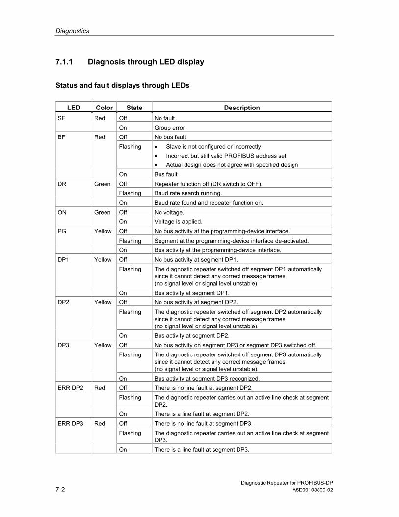
Diagnostics
Diagnostic Repeater for PROFIBUS-DP7-2 A5E00103899-02
7.1.1 Diagnosis through LED display
Status and fault displays through LEDs
LED Color State DescriptionSF Red Off No fault
On Group errorBF Red Off No bus fault
Flashing • Slave is not configured or incorrectly• Incorrect but still valid PROFIBUS address set• Actual design does not agree with specified design
On Bus faultDR Green Off Repeater function off (DR switch to OFF).
Flashing Baud rate search running.On Baud rate found and repeater function on.
ON Green Off No voltage.On Voltage is applied.
PG Yellow Off No bus activity at the programming-device interface.Flashing Segment at the programming-device interface de-activated.On Bus activity at the programming-device interface.
DP1 Yellow Off No bus activity at segment DP1.Flashing The diagnostic repeater switched off segment DP1 automatically
since it cannot detect any correct message frames(no signal level or signal level unstable).
On Bus activity at segment DP1.DP2 Yellow Off No bus activity at segment DP2.
Flashing The diagnostic repeater switched off segment DP2 automaticallysince it cannot detect any correct message frames(no signal level or signal level unstable).
On Bus activity at segment DP2.DP3 Yellow Off No bus activity on segment DP3 or segment DP3 switched off.
Flashing The diagnostic repeater switched off segment DP3 automaticallysince it cannot detect any correct message frames(no signal level or signal level unstable).
On Bus activity at segment DP3 recognized.ERR DP2 Red Off There is no line fault at segment DP2.
Flashing The diagnostic repeater carries out an active line check at segmentDP2.
On There is a line fault at segment DP2.ERR DP3 Red Off There is no line fault at segment DP3.
Flashing The diagnostic repeater carries out an active line check at segmentDP3.
On There is a line fault at segment DP3.

Diagnostics
Diagnostic Repeater for PROFIBUS-DPA5E00103899-02 7-3
Fault displays through LEDs
LEDSF BF DR ON
Meaning Cause
Off Off Off Off No voltage Voltage not applied.Off On Flashing On No connection to DP
master• Bus connection interrupted• DP master does not exist / is de-
activatedOff Flashi
ngOn On Parameter assignment
error,there is no dataexchange taking place.
• Slave is not configured or incorrectly• Incorrect but still valid PROFIBUS
address set• Actual design does not agree with
specified designOn Off On On Error in the slave There is (at least) one diagnosis n the slave
- the slave is exchanging dataOff Off On On Data exchange No faultFlashing Fla-
shingFlashing On PROFIBUS address Impermissible PROFIBUS address set: 0,
126, 127Off/on Off/on/
fla-shing
Off On Repeater function off DR switch to OFF

Diagnostics
Diagnostic Repeater for PROFIBUS-DP7-4 A5E00103899-02
7.1.2 Diagnosis with STEP 7 and COM PROFIBUS
RequirementsIn order to receive correct distance specifications in the diagnostic messages thetopology determination has to be updated after every change in the bus structure!
Visualizing the diagnosisThe diagnostic messages can be visualized for example by means of the followingtools and menu commands:
• STEP 7: PLC > Module Information
• Signal System Faults (at operator control and monitoring device)
• COM PROFIBUS: Service > Slave Diagnostics
• PROFIBUS Diagnostic Package (S7 diagnostic block FB 125)
Reporting system faultsOperator control and monitoring devices, for example OPs, are connected at thePROFIBUS or via the MPI interface to the CPU of the DP master. The operatorcontrol and monitoring device fetches the diagnostic information from this CPU.The message texts are generated in STEP 7 and can be visualized with theoperator control and monitoring devices.
Further information can be found in the manual Programming with Step 7 V 5.1 inthe section "Signaling System Faults"
Reading out current diagnostic messagesThe diagnostic messages of the diagnostic repeater can be read out in the userprogram using SFC 13 "DP NRM_DG" and stored in the data area.
Further information can be found in the on-line help system of STEP 7.
S7 diagnostic block FB 125The S7 diagnostic block can be found in the Internet under
http://www4.ad.siemens.de/view/cs/de/387257

Diagnostics
Diagnostic Repeater for PROFIBUS-DPA5E00103899-02 7-5
7.2 Structure of the diagnosis
7.2.1 Structure of the slave diagnosis
Byte 0 Station status 1
Byte 1 Station status 2Byte 2 Node status 3Byte 3 Master PROFIBUS addressByte 4 Manufacturer identifier (high byte)Byte 5 Manufacturer identifier (low byte)Byte 6 Identifier-specific diagnosisByte 7 Identifier-specific diagnosisByte 8..Byte 26
Device-specific diagnosis: line fault status segment DP2
Byte 27..Byte 45
Device-specific diagnosis: line fault status segment DP3
Byte 46..Byte 64
Device-specific diagnosis: line fault status segment DP1
Byte 65..Byte 83
Device-specific diagnosis: line fault status programming deviceinterface
Byte 84..Byte 90
Device-specific diagnosis: TSYNC diagnostic module
NoteThe length of the diagnostic frame varies between 6, 27, 46, 65, 84 or 91 bytes.You can find out the length of the last diagnostic frame received in STEP 7 fromthe "RET_VAL" parameter of SFC 13.

Diagnostics
Diagnostic Repeater for PROFIBUS-DP7-6 A5E00103899-02
7.2.2 Node status 1 to 3
DefinitionThe node status 1 to 3 provides an overview of the state of a DP slave.
Station status 1
Bit Meaning Cause/remedy
0 1: The DP slave cannot be addressed by the DPmaster.
• Correct PROFIBUS address set at the DPslave?
• Bus connector connected?• Voltage at DP slave?• RS 485 repeater set correctly?• Reset carried out at DP slave?
1 1: The DP slave is not yet ready for the dataexchange.
• Wait, since the DP slave is just startingup.
2 1: The configuration data sent from the DPmaster to the DP slave do not agree with thedesign of the DP slave.
• Correct design of the DP slave entered inthe configuration software? Evaluate theidentifier-specific diagnosis.
3 1: There is an extended diagnosis available.(group diagnosis display)
• Evaluate the device-specific diagnosis(line fault status). Bit 3 is reset as soon asall the faults have been eliminated. The bitis set again when a new diagnosticmessage exists in the bytes of the device-specific diagnosis.
4 1: The requested function is not supported by theDP slave (e.g. changing the PROFIBUSaddress via the software).
• Check the configuration.
5 1: DP master cannot interpret the answer of theDP slave.
• Check the bus design.
6 1: The DP slave type does not agree with thesoftware configuration.
• Correct node type entered in theconfiguration software?
7 1: The DP slave has been configured from adifferent DP master (not from the DP masterwhich currently has access to the DP slave).
• Bit is always 1 when you are e.g.accessing the DP slave with the PG orwith another DP master. The PROFIBUSaddress of the DP master whichconfigured the DP slave is contained inthe diagnostic byte "Master PROFIBUSaddress".

Diagnostics
Diagnostic Repeater for PROFIBUS-DPA5E00103899-02 7-7
Station status 2
Bit Meaning
0 1: The DP slave has to be configured again.1 1: There is a diagnostic message. The DP slave does not function until the fault
has been eliminated (static diagnostic message).2 1: The bit is always set to 1 in the DP slave.3 1: The response monitoring is activated at this DP slave.4 1: The DP slave has received the control command "FREEZE".1
5 1: The DP slave has received the control command "SYNC".1
6 0: Bit is always set to 0.7 1: The DP slave is de-activated, meaning that is has been removed from the
current processing.
1 The bit is updated only if another diagnostic message changes, too.
Node status 3
Bit Meaning
0 to 6 0: Bits are always set to 0.7 1: • There are more diagnostic messages than the DP slave can save.
• The DP master cannot enter all the diagnostic messages sent by the DPslave in its diagnostic buffer (device-specific diagnosis)
7.2.3 Master PROFIBUS address
DefinitionThe diagnostic byte Master PROFIBUS address is contained in the PROFIBUSaddress of the DP master:
• Which has configured the DP slave and
• Which has reading and writing access to the DP slave.
The Master PROFIBUS address is contained in Byte 3 of the Slave diagnosis.

Diagnostics
Diagnostic Repeater for PROFIBUS-DP7-8 A5E00103899-02
7.2.4 Manufacturer identifier
DefinitionThe manufacturer ID contains a code that describes the type of the DP slave.
Manufacturer identifier
Byte 4 Byte 5 Manufacturer identifier for
80H A7H Diagnostic repeater
7.2.5 Structure of the module diagnosis
DefinitionThe identifier-specific diagnosis provides information on whether the diagnosticrepeater has been configured incorrectly or not. The identifier-specific diagnosisencompasses bytes 6 and 7.
Identifier-specific diagnosisThe identifier-specific diagnosis for the diagnostic repeater has the followingstructure:
Byte MSB 7 6 5 4 3 2 1
LSB 0
6 0 1 0 0 0 0 1 0 Code for
identifier-specificdiagnosis
Length of the identifier-specific diagnosis (2 bytes)
7 0 0 0 0 0 0 0 1 Events on the module are signaled by set bits.

Diagnostics
Diagnostic Repeater for PROFIBUS-DPA5E00103899-02 7-9
7.2.6 Structure of the device-specific diagnosis
Line fault statusThe following section describes the structure of the line fault status of segmentsDP1, DP2, and DP3 and of the programming device interface.
Byte MSB 7 6 5 4 3 2 1
LSB 0
1 0 0 Block length = 19 Length2 1 Status type line fault = 32 Type3 0: Slot number Slot4 res. Specifier5 Segment res. res. res. res.
6
Version res. res. LD Topo-logyON/OFF
Seg-mentON/OFF
res.
7 Fault rate
Errorinformation
8 Node x9 Node y10 Distance [0] from station x (high byte)11 Distance [1] from station x (low byte)12 Distance [0] from station y (high byte)13 Distance [1] from station y (low byte)14 Distance [0] from the diagnostic repeater (high byte)15 Distance [1] from the diagnostic repeater (low byte)
Fault location
16 A.7 A.6 A.5 A.4 A.3 A.2 A.1 A.017 B.7 B.6 B.5 B.4 B.3 B.2 B.1 B.018 C.7 C.6 C.5 C.4 C.3 C.2 C.1 C.0
19 res.Error cause
res. Reserved bits are occupied with "0".

Diagnostics
Diagnostic Repeater for PROFIBUS-DP7-10 A5E00103899-02
Error information
Range Description
Segment Bit 4Bit 5Bit 6Bit 7
Segment DP3Segment DP2Segment DP1Programming device interface
0 Segment DP3 ONSegmentON/OFF
Bit 1 1 Segment DP3 OFF0 Topology determination on DP2 or DP3 ONTopology
ON/OFFBit 2
1 Topology determination on DP2 or DP3 OFF0 There is no fault in the affected segment
(all bits A.0 to C.7 = 0)LD(line diagnosis)
Bit 3
1 There is a fault in the affected segment(at least one bit from A.0 to C.7 = 1)
Bit 6 01
DR 6ES7 972-0AB00-0XA0DR 6ES7 972-0AB01-0XA0On the basis of the version, a software package can identify whether ornot the LD bit is to be evaluated.
Version
Bit 7 0 –Fault rate Bit
0 to 6Value range from 0 to 100%The value FFH means that there is no error rate for the relevant diagnosticevent.

Diagnostics
Diagnostic Repeater for PROFIBUS-DPA5E00103899-02 7-11
Fault locationThe information on the fault location is only relevant to segments DP2 and DP3.
Range Description
Bit0 to 6
Addresses of the stations between which there is a line fault.
0 The distance specification of the node is not up to date.The distance specification of a node is not up to date if topologydetermination has not been carried out after voltage recovery or for acertain period.
Station x,Station y
Bit 7
1 The distance specification of the node is up to date.
Distance[0, 1] from x
Bit0 to 7
Distance of the reflection point from node x.The specification is made in the unit "decimeters".If either 7FH or FFH is entered in "station x", the parameter "Distance[0, 1] from x" cannot be evaluated.
Distance[0, 1] from y
Bit0 to 7
Distance of the reflection point from node y.The specification is made in the unit "decimeters".If either 7FH or FFH is entered in "station y", the parameter "Distance[0, 1] from y" cannot be evaluated.
Distance[0, 1] from DR
Bit0 to 7
Distance of the reflection point from the diagnostic repeater.The specification is made in the unit "decimeters".The value FFH means that the distance from the fault location to thediagnostic repeater cannot be specified for the relevant diagnostic event.
Special cases: area station x, station y
Special case Station x = ... Station y = ...
Fault point for one or more nodesto do with ≤measurement accuracy
Address of a node(representative)
FFH
Fault location before the first station Separate address First stationFault location after the last station Last station 7FHFault location at a node Address of the node FFHFault location unknown FFH FFHFurther measuring circuit in thesegment
Separate station address Station connected toseparate station by meansof measuring circuit
Node too far away Separate station address Node too far awayMaximum cascade depth exceeded Separate station address Station at other end of the
cascade

Diagnostics
Diagnostic Repeater for PROFIBUS-DP7-12 A5E00103899-02
Error cause
Bit Description
A.0 1: Fault location and cause not clear(possibly electromagnetic interference).
A.1 1: -A.2 1: -A.3 1: Further measuring circuits at the segment, the other diagnostic repeater is
connected with its segment DP2.A.4 1: Further measuring circuits at the segment, the other diagnostic repeater is
connected with its segment DP3.A.5 1: –A.6 1: Error cause is not clear.A.7 1: Message fault rate is critical.B.0 1: Break in the signal line A.B.1 1: Short circuit between signal line B to screen.B.2 1: –B.3 1: Short circuit between signal line A to screen.B.4 1: Break in the signal line B.B.5 1: –B.6 1: Break in signal line A and/or B or
no terminating resistor.B.7 1: Short circuit between signal line A and/or B or
an additional terminating resistor has been inserted.C.0 1: Segment de-activated automatically, because line level constantly zero.C.1 1: Segment de-activated automatically, because line level constantly unsteady.C.2 1: –C.3 1: –C.4 1: More than 32 nodes are connected to the measuring segment.C.5 1: The distance of the node to the diagnostic repeater exceeds the permitted
line length.C.6 1: The maximum permitted number of diagnostic repeaters connected in series
is exceeded.C.7 1: The diagnostic repeater has recognized further faults.

Diagnostics
Diagnostic Repeater for PROFIBUS-DPA5E00103899-02 7-13
7.2.7 Monitoring function of the clocked PROFIBUS bus system
Diagnostic messageIf the diagnostic repeater detects a TDX and/or TDP violation, it generates acorresponding diagnostic message. The diagnostic for the display of the TDX orTDP violation is structured as follows:
Byte MSB 7 6 5 4 3 2 1
LSB 0
1 0 0 Block length = 7 Length 2 1 Status type TSYNC fault = 33 (dec) Type 3 Slot number = 0 Slot 4 Reserved = 0 Specifier 5 Cycle counter [high] Cycle counter 6 Cycle counter [low] 7 TSYNC diagnostic status Error
information
Structure of error information: TSYNC diagnostic status
Bit Meaning1 TDP violation detected in the cycle (see cycle counter)Bit 00 No TDP violation detected1 TDX violation detected in the cycle (see cycle counter)Bit 10 No TDX violation detected1 TSYNC parameter block error (times are not correct)Bit 20 TSYNC parameter block without error
Bits3 to 7
0 Reserved
Structure of input data: TSYNC diagnostic moduleIn order to establish a defined assignment from the diagnostic event to the relevantcycle, the cycle counter and a status byte can be displayed in the input area of thediagnostic repeater through the TSYNC diagnostic module.The input data of the diagnostic repeater with the configured TSYNC diagnosticmodule are structured as follows:
Byte MSB 7 6 5 4 3 2 1
LSB 0
1 Cycle counter [high] 2 Cycle counter [low]
Cycle counter
3 TSYNC diagnostic status Errorinformation
The TSYNC diagnostic module has an output byte whose content is not evaluated.This is required for the detection of the TDX violation.

Diagnostics
Diagnostic Repeater for PROFIBUS-DP7-14 A5E00103899-02
7.3 Reading data out in the user program
The topology table, the diagnostic buffer, and the statistics buffer can be read outin the user program using SFC 59 "RD_REC" or SFB 52 "RDREC".
7.3.1 Topology table
Records
Recordnumber (hex)
Recordnumber (dec)
Writable/readable W / R
Function
32H 50 R 1st part of the topology tableNodes 0 to 31; length = 170 bytes
33H 51 R 2nd part of the topology tableNodes 32 to 63; length = 170 bytes
34H 52 R 3rd part of the topology tableNodes 64 to 95; length = 170 bytes
35H 53 R 4th part of the topology tableNodes 96 to 126; length = 165 bytes
Structure of the topology table
Topology table record x Number of bytes
Constant 02 1 byteStatus information 1 1 byteTime stamp 2 8 bytes
Topology entry x Status/substatus 1 byteDistance (in decimeters) 2 bytesSegment 1 byte
DR information
1 byte
...Topology entryx + 1
Topology entry ... ...
...Topology entryx + n (n = max. 32)
1 The status information is only contained in the first record. In the other recordsof the topology table this byte is occupied with 00H.
2 The time stamp is only contained in the first record. In the other records of thetopology table this entry is occupied with 00H.
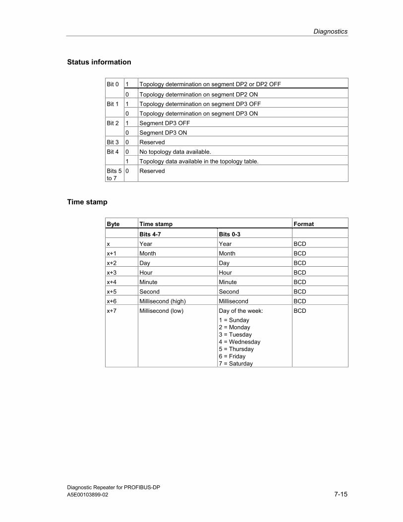
Diagnostics
Diagnostic Repeater for PROFIBUS-DPA5E00103899-02 7-15
Status information
1 Topology determination on segment DP2 or DP2 OFFBit 0
0 Topology determination on segment DP2 ON1 Topology determination on segment DP3 OFFBit 10 Topology determination on segment DP3 ON1 Segment DP3 OFFBit 20 Segment DP3 ON
Bit 3 0 Reserved0 No topology data available.Bit 41 Topology data available in the topology table.
Bits 5to 7
0 Reserved
Time stamp
Byte Time stamp Format
Bits 4-7 Bits 0-3x Year Year BCDx+1 Month Month BCDx+2 Day Day BCDx+3 Hour Hour BCDx+4 Minute Minute BCDx+5 Second Second BCDx+6 Millisecond (high) Millisecond BCDx+7 Millisecond (low) Day of the week:
1 = Sunday2 = Monday3 = Tuesday4 = Wednesday5 = Thursday6 = Friday7 = Saturday
BCD
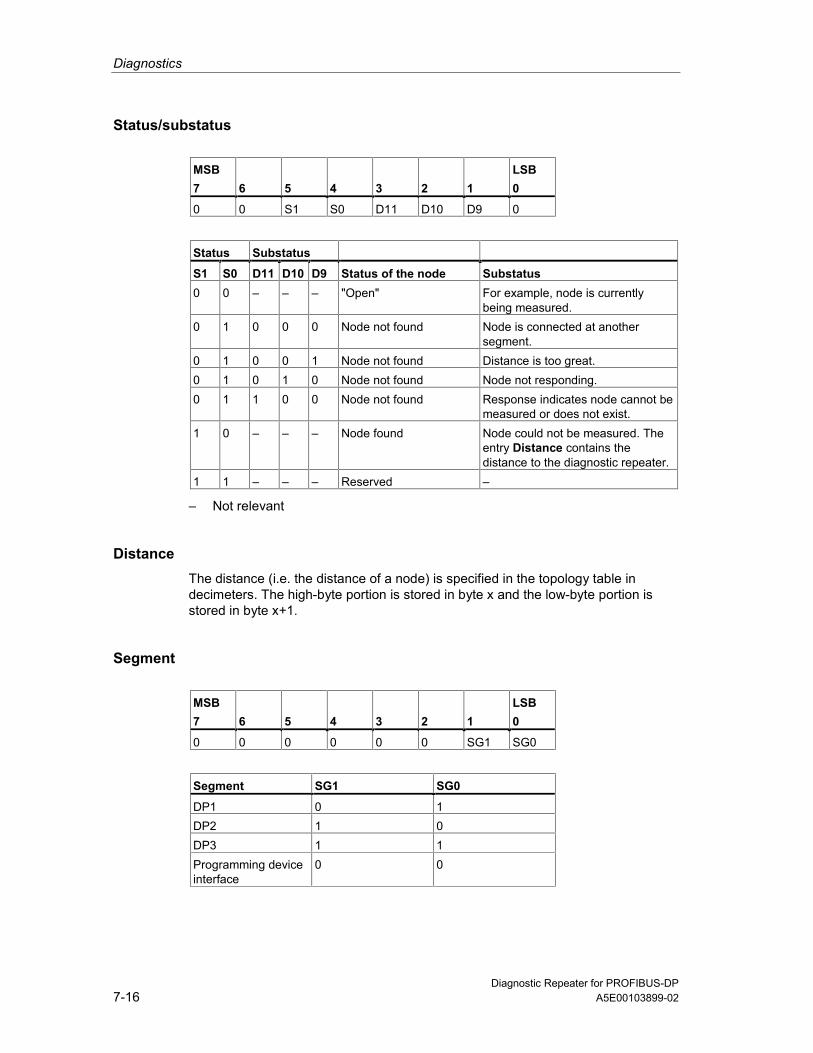
Diagnostics
Diagnostic Repeater for PROFIBUS-DP7-16 A5E00103899-02
Status/substatus
MSB 7
6
5
4
3
2
1
LSB 0
0 0 S1 S0 D11 D10 D9 0
Status Substatus S1 S0 D11 D10 D9 Status of the node Substatus0 0 – – – "Open" For example, node is currently
being measured.0 1 0 0 0 Node not found Node is connected at another
segment.0 1 0 0 1 Node not found Distance is too great.0 1 0 1 0 Node not found Node not responding.0 1 1 0 0 Node not found Response indicates node cannot be
measured or does not exist.1 0 – – – Node found Node could not be measured. The
entry Distance contains thedistance to the diagnostic repeater.
1 1 – – – Reserved –
– Not relevant
DistanceThe distance (i.e. the distance of a node) is specified in the topology table indecimeters. The high-byte portion is stored in byte x and the low-byte portion isstored in byte x+1.
Segment
MSB 7
6
5
4
3
2
1
LSB 0
0 0 0 0 0 0 SG1 SG0
Segment SG1 SG0
DP1 0 1DP2 1 0DP3 1 1Programming deviceinterface
0 0

Diagnostics
Diagnostic Repeater for PROFIBUS-DPA5E00103899-02 7-17
DR information
MSB 7
6
5
4
3
2
1
LSB 0
DS1 DS0 ME KF 0 0 0 DR
DR - Diagnostic repeater
This bit is set when the response of a diagnostic repeater has been received.
KF - Cascade depth error
This bit is relevant only when DR=1. In this case, the relevant node is a diagnosticrepeater where the maximum permissible cascade depth has been exceeded.
ME - Measuring circuit
This bit is relevant only when DR=1. In this case, the node is a diagnostic repeaterconnected to this diagnostic repeater and its segment SG1, SG0. If the bit is set,there are two measuring circuits in this segment.
DS0, DS1 - Diagnostic repeater segment
These bits are relevant only when DR=1. In this case, these bits indicate whichsegment of the other diagnostic repeater is connected to this diagnostic repeater.
Segment DS1 DS0
DP1 0 1DP2 1 0DP3 1 1Programming deviceinterface
0 0
7.3.2 Diagnostic buffer
Records
Recordnumber (hex)
Recordnumber (dec)
Writable/readable W / R
Function
1EH 30 R Diagnostic buffer DP11FH 31 R Diagnostic buffer DP220H 32 R Diagnostic buffer DP321H 33 R Diagnostic buffer PG
(programming device)

Diagnostics
Diagnostic Repeater for PROFIBUS-DP7-18 A5E00103899-02
Structure of the diagnostic bufferFor each PROFIBUS segment the diagnostic repeater supplies a diagnostic bufferin which the last 10 events are stored together with their date and time.
Diagnostic buffer DPx Number of bytes
Constant 02 1 byteStatus information 1 byteSegment data 1 byteNumber of entries 1 byte
Entry 1 Time stamp 8 bytesDiagnostic entry x 15 bytes
Entry 2 Time stamp 8 bytesDiagnostic entry x+1 15 bytes
Entry ... Time stamp 8 bytesDiagnostic entry ... 15 bytesTime stamp 8 bytesEntry x + n
(n = max. 10) Diagnostic entry y 15 bytes
Status information
1 Topology determination on segment DP2 OFFBit 0
0 Topology determination on segment DP2 ON1 Topology determination on segment DP3 OFFBit 10 Topology determination on segment DP3 ON1 Segment DP3 OFFBit 20 Segment DP3 ON1 Segment disturbed (at least one incoming error has yet not been reported as
departed)Bit 3
0 Segment not disturbed (all errors departed)Bit 4to 7
0 Reserved
The status information is kept in accordance with the segment affected.
Segment Bit 0 Bit 1 Bit 2 Bit 3
DP1 0 0 0 1/0DP2 1/0 0 0 1/0DP3 0 1/0 1/0 1/0Programmingdevice interface
0 0 0 1/0

Diagnostics
Diagnostic Repeater for PROFIBUS-DPA5E00103899-02 7-19
Segment data
Bit0 to 3
0 Reserved
Bit 4 1 Segment: DP3Bit 5 1 Segment: DP2Bit 6 1 Segment: DP1Bit 7 1 Programming device interface
Number of entriesThe "Number of entries" parameter indicates how many entries are contained inthe buffer. This information is necessary since, for a read request of 240 bytes, thediagnostic repeater always returns the full length of 234 bytes, regardless of thenumber of entries that exist.
If a read request is made and there is no entry in the buffer, the parameter"Number of entries" = 0, and the other bytes are filled with "0".
Time stamp
Time stamp Number of bytes
Bits 4-7 Bits 0-3Year Year 1 byteMonth Month 1 byteDay Day 1 byteHour Hour 1 byteMinute Minute 1 byteSecond Second 1 byteMillisecond (high) Millisecond 1 byteMillisecond (low) Day of the week:
1 = Sunday2 = Monday3 = Tuesday4 = Wednesday5 = Thursday6 = Friday7 = Saturday
1 byte

Diagnostics
Diagnostic Repeater for PROFIBUS-DP7-20 A5E00103899-02
Diagnostic entry
Byte MSB 7 6 5 4 3 2 1
LSB 0
1 Segment res. res. res. I/O
2
Version res. res. LD Topo-logyON/OFF
Seg-mentON/OFF
res.
3 Fault rate
Errorinformation
4 Node x5 Node y6 Distance [0] from station x (high byte)7 Distance [1] from station x (low byte)8 Distance [0] from station y (high byte)9 Distance [1] from station y (low byte)10 Distance [0] from the diagnostic repeater (high byte)11 Distance [1] from the diagnostic repeater (low byte)
Fault location
12 A.7 A.6 A.5 A.4 A.3 A.2 A.1 A.013 B.7 B.6 B.5 B.4 B.3 B.2 B.1 B.014 C.7 C.6 C.5 C.4 C.3 C.2 C.1 C.0
15 res.
Error cause
I/O Diagnostic event incoming (0)/outgoing (1)
res. Reserved bits are occupied with "0".
The meaning of the remaining bits is described in Section 7.2.6.
7.3.3 Statistics buffer
Records
Record number (hex)
Record number (dec)
Writable/readable W / R
Function
28H 40 R Reflection error rate DP229H 41 R Message frame error rate DP22AH 42 R Reflection error rate DP32BH 43 R Message frame error rate DP3

Diagnostics
Diagnostic Repeater for PROFIBUS-DPA5E00103899-02 7-21
Structure of the statistics buffer
Statistics buffer DPx Number of bytes
Constant 02 1 byteStatus information 1 byteSegment data 1 byteNumber of entries 1 byte
Entry 1 Time stamp 8 bytesStatistics entry x 1 byte
Entry 2 Time stamp 8 bytesStatistics entry x+1 1 byte
Entry ... Time stamp 8 bytesStatistics entry ... 1 byteTime stamp 8 bytesEntry x + n
(n = max. 26) Statistics entry y 1 byte
Status information
1 Topology determination on segment DP2 or DP2 OFFBit 0
0 Topology determination on segment DP2 ON1 Topology determination on segment DP3 OFFBit 10 Topology determination on segment DP3 ON1 Segment DP3 OFFBit 20 Segment DP3 ON1 Segment disturbed (at least one incoming error has yet not been reported as
departed)Bit 3
0 Segment not disturbed (all errors departed)Bit 4to 7
0 Reserved
The status information is kept in accordance with the segment affected.
Segment Bit 0 Bit 1 Bit 2 Bit 3
DP1 0 0 0 1/0DP2 1/0 0 0 1/0DP3 0 1/0 1/0 1/0Programmingdevice interface
0 0 0 1/0

Diagnostics
Diagnostic Repeater for PROFIBUS-DP7-22 A5E00103899-02
Segment data
Bit0 to 3
0 Reserved
Bit 4 1 Segment: DP3Bit 5 1 Segment: DP2Bit 6 1 Segment: DP1Bit 7 1 Programming device interface
Number of entriesThe "Number of entries" parameter indicates how many entries are contained inthe buffer. This information is necessary since, for a read request of 240 bytes, thediagnostic repeater always returns the full length of 238 bytes, regardless of thenumber of entries that exist.
If a read request is made and there is no entry in the buffer, the parameter"Number of entries" = 0, and the other bytes are filled with "0".
Time stamp
Byte Time stamp Format
Bits 4-7 Bits 0-3x Year Year BCDx+1 Month Month BCDx+2 Day Day BCDx+3 Hour Hour BCDx+4 Minute Minute BCDx+5 Second Second BCDx+6 Millisecond (high) Millisecond BCDx+7 Millisecond (low) Day of the week:
1 = Sunday2 = Monday3 = Tuesday4 = Wednesday5 = Thursday6 = Friday7 = Saturday
BCD

Diagnostics
Diagnostic Repeater for PROFIBUS-DPA5E00103899-02 7-23
Statistics entryThe statistics entry contains the number of errored message frames as apercentage.
The statistics entries are formed as follows:
Reflection error rate =Message frames with reflections/number of message frames sent * 100
Message frame error rate =Message frames with bit errors/number of message frames received * 100
The entries in the statistics buffer (message frame and reflection errors) occur atregular intervals. The following update times apply between two entries, dependingon the baud rate:
Baud rate Update time
12 Mbps Approx. 300 ms1.5 Mbps Approx. 180 ms500 kbps Approx. 1.54 s187.5 kbps Approx. 1.54 s19.2 kbps Approx. 3.2 s9.6 kbps Approx. 3.2 s

Diagnostics
Diagnostic Repeater for PROFIBUS-DP7-24 A5E00103899-02
7.4 Topology display in STEP 7
7.4.1 Topology data: bus topology and topology table
Bus topologyThe bus topology contains the following information:
• Nodes (master, slaves, diagnostic repeaters)
• Distance of the nodes from the diagnostic repeaters
The following functions are available:
• Show/hide segments
• Search for nodes
• Select nodes
The bus topology can be printed out and exported as a CSV file.
Procedure1. In STEP 7 select the DP master system whose data you want to read.
2. Start the function by choosing the menu command View > Display > AllStations/Only Diagnostic Repeater with Stations/All Diagnostic RepeatersOnly.

Diagnostics
Diagnostic Repeater for PROFIBUS-DPA5E00103899-02 7-25
Bus topology example
Topology tableThe topology table contains the following information:
• PROFIBUS address of the node.
• The designation of the node, if ascertainable.
• Address of the associated diagnostic repeater to whose measurementsegment the node is connected.
• Distance in relation to the associated diagnostic repeater.
• Segment of the diagnostic repeater to which the node is connected.
• The time at which the topology was last determined.
The topology table can be printed out. It can be exported as a CSV file and thenread into Microsoft Excel and evaluated.
It can also be read out using the user program (see Section 7.3.1).
Procedure1. In the topology display, select the diagnostic repeater whose data you want to
read.
2. Start the function by choosing the View > Topology table menu command.

Diagnostics
Diagnostic Repeater for PROFIBUS-DP7-26 A5E00103899-02
Topology table example
7.4.2 Diagnostic buffer
For each of segments DP1, DP2, and DP3 as well as the programming deviceinterface, the diagnostic repeater contains a diagnostic buffer in which the last 10results are saved. The buffer contains the time, date, and a brief description of theresults. Incoming errors are marked with K or I, and outgoing errors are markedwith G or O.
The diagnostic buffers can be printed out. They can be exported as a CSV file andthen read into Microsoft Excel and evaluated.
The diagnostic buffers can also be read out using the user program (see Section7.3.2).
Procedure1. In the topology display, select the diagnostic repeater whose data you want to
read.
2. Start the function by choosing the Options > Diagnostic buffer menucommand.

Diagnostics
Diagnostic Repeater for PROFIBUS-DPA5E00103899-02 7-27
Diagnostic buffer example

Diagnostics
Diagnostic Repeater for PROFIBUS-DP7-28 A5E00103899-02
7.4.3 Statistics buffer
For each of segments DP2 and DP3 the diagnostic repeater contains a statisticsbuffer in which information on the reflection error rate and message frame errorrate is saved.
Reflection errors occur, for example, when the signal is reflected by a disturbed ordefective line.
Message frame errors are detected, for example, when message frames with parityerrors occur. Parity errors can be caused by a defective node, for example.
The values are displayed for a period of 60 seconds as of the point at which thedialog is opened. Other values are saved internally beyond this period.
The statistics buffers can be printed out. They can be exported as a CSV file andthen read into Microsoft Excel and evaluated.
The statistics buffers can also be read out using the user program (see Section7.3.3).
Procedure1. In the topology display, select the diagnostic repeater whose data you want to
read.
2. Start the function by choosing the Options > Statistics menu command.
Procedure in the event of line problemsIf there are line problems, change to the diagnostic buffer to get information on thelocation and cause of the problem.

Diagnostics
Diagnostic Repeater for PROFIBUS-DPA5E00103899-02 7-29
Statistics buffer example
The statistics buffer reflects the quality of the bus system:
(1) There are too many problems on the line. Operation of the segment is no longerpossible.
(2) There are problems on the line. Operation of the segment is still possible.However, it is possible that nodes may fail.
(3) There are few problems on the line. Operation of the segment is optimal.
In addition, the color coding helps you estimate the severity of the problems.
1
2
3

Diagnostics
Diagnostic Repeater for PROFIBUS-DP7-30 A5E00103899-02
7.4.4 Error messages
Example of an error messageThe figure below indicates how an error message is structured in STEP 7.
The tab cards DP1, DP2, DP3 and PG each contain the diagnostic information forthe corresponding segment. An icon indicates whether the segment is faulty or notand whether it is de-activated.
Three output fields contain graphic and text information on the fault location, typeof fault, remedy and, if appropriate, information on the reflection fault rate.
The "Details" command button leads to further information on the faults, fault causeand remedy.
Diagnostic Repeater,reporting problem;DP2 indicates theaffected segment.
Fault locationon line
DP slavePB address 6
Segment problem Segment ok
Relative distance
Absolute distance offault point fromdiagnostic repeater
D:\SIMATIC300(1)\PB_Netz(4)

Diagnostics
Diagnostic Repeater for PROFIBUS-DPA5E00103899-02 7-31
Fault location: how exact is the distance information?All distance specifications have a tolerance of ±1 m. The error can therefore alsohave occurred at neighboring nodes which lie within the tolerance to the specifiednode.
Reflection fault rateThe reflection fault rate specifies the number of messages at which a reflectionoccurred in the form of a percentage.
The reflection fault rate is indicated at the diagnostic messages.
7.5 Diagnostic messages and fault elimination
7.5.1 Design guidelines not observed
The following tables contain the diagnostic messages which are displayed inSTEP 7 and COM PROFIBUS.
More than 32 nodes are connected to the measuring segment
Description Remedy
A maximum of 32 nodes may be connected at aPROFIBUS segment. If this maximum isexceeded, the message traffic in this segment isno longer ensured. The diagnostic repeater itselfalso counts as a node.Note:The SF LED shines red as soon as topologydetermination has been carried out.
Reduce the number of nodes at this segment.If you use a further diagnostic repeater, you cancreate two further segments for 31 nodes each. Amaximum of 9 diagnostic repeaters can be connectedin series.Carry out the topology determination again aftercompleting the changes.
If, contrary to the design guidelines of thediagnostic repeater, this segment contains acomponent with repeater function, such as anRS 485 repeater or an Optical Link Module (OLM),the nodes behind it are counted as well. This thenalso causes a fault message.Note:The line diagnostic only functions up to thecomponent with repeater function. Everydownstream node is indicated with the distance ofthe component with repeater function.
Suppressing the fault message:In this case, you can suppress the error message byswitching off topology determination for this segmentwhen configuring the diagnostic repeater (see Section6.3.2).

Diagnostics
Diagnostic Repeater for PROFIBUS-DP7-32 A5E00103899-02
The maximum permitted number of diagnostic repeaters connected in series isexceeded
Description Remedy
A maximum of 9 diagnostic repeaters can beconnected in series.
Note:The SF LED shines red as soon as topologydetermination has been carried out.
Limit the number of diagnostic repeaters connected inseries to a maximum of 9.Carry out the topology determination again aftercompleting the changes.
The distance of the node to the diagnostic repeater exceeds the permitted linelength
Description Remedy
The diagnostic repeater signals when a node istoo far away from it.
Note:The SF LED shines red as soon as topologydetermination has been carried out.
Insert one or more diagnostic repeaters into thesegment so that the maximum line length which ispermissible and can be monitored of 100 m persegment is not exceeded.
More than one measurement circuit in segment
Description Remedy
A further diagnostic repeater with the interfaceDP2 or DP3 is connected.The diagnostic repeater has two interfaces withmeasuring circuits (DP2 and DP3) and aninterface without measuring circuit (DP1). Nofurther measuring circuit may be connected tosegment DP2 or DP3. Further diagnosticrepeaters may only still be connected with theinterface DP1.
Note:The SF LED shines red as soon as topologydetermination has been carried out.
Change the network design so that further diagnosticrepeaters at this segment are only connected with theinterface DP1.The programming device interface may only be usedto connect a programming device.

Diagnostics
Diagnostic Repeater for PROFIBUS-DPA5E00103899-02 7-33
7.5.2 Message frame error rate in the segment is critical
Description Remedy
This fault occurs when the message traffic is nolonger free of errors, e.g. due to faulty bits. In thiscase the data exchange is no longer ensured.
Check whether the PROFIBUS cable conforms to thedesign guidelines (e.g. shielding, grounding andterminators, see Section 3.1) and that there are noloose contacts.Hint:The cause of the fault can possibly be isolated bychecking the segment section-by-section. To do so,cut in the terminator at the PROFIBUS connectors sothat the outgoing line is separated.
Possible causes:• Several nodes have the same PROFIBUS
address.Correct the PROFIBUS addresses of the nodes.Typically the set PROFIBUS address is not acceptedby the node until after a Power OFF/ON.
• Nodes at this segment operate with differentbaud rates. Not all the PROFIBUS nodes findthe baud rate automatically.
Check whether all the bus nodes in this segmentoperate with the same baud rate. Set the baud rate atthe node and/or in the configuration correctly. Atsome devices the baud rate is set by means ofswitches on the device or configuration.
• Defective PROFIBUS interface at a node.• The PROFIBUS interface can be damaged by
potential differences or overvoltages.Check whether a sufficiently high equipotentialbonding is installed in order to avoid equipotentialdifferences.
• Electromagnetic interference. Eliminate any possible sources of electromagneticinterference.

Diagnostics
Diagnostic Repeater for PROFIBUS-DP7-34 A5E00103899-02
7.5.3 Break in the signal wire A or B
Description Remedy
A wire break has occurred at the displayedlocation.Possible causes:• Damaged wire (e.g. high mechanical stress,
vibration, bending radius too narrow),• A signal wire not connected properly in the
PROFIBUS connector,• Mechanical stress can cause the signal wires
in the PROFIBUS connector to break or nolonger to contact,
• Defective PROFIBUS connector.
In the area of the displayed fault location check thesegment for:• Damage to the wire,• Correct mounting of the PROFIBUS
connectors/connections,• Defective PROFIBUS node (e.g. through the
device being switched off or my removing thePROFIBUS connector).
7.5.4 Short circuit in the signal wire A and B or short circuit in thesignal wire A or B to screen
Description Remedy
A wire short circuit has occurred at the displayedlocation.Possible causes:• Damaged wire (e.g. high mechanical stress,
vibration, pinching, bending radius toonarrow),
• Signal wires not connected properly in thePROFIBUS connector,
• Ingress of conductive liquids,• Badly stripped or loose braided shield
contacts the signal wire,• Defective PROFIBUS interface at the
connected node,• Existing spur lines.
In the area of the displayed fault location check thesegment for:• Damage to the wire,• Correct mounting of the PROFIBUS connectors
connections,• Defective PROFIBUS node (e.g. through the
device being switched off or my removing thePROFIBUS connector),
• Spur lines.

Diagnostics
Diagnostic Repeater for PROFIBUS-DPA5E00103899-02 7-35
7.5.5 Terminator
Description Remedy
Terminator missing:Terminator was not connected at a node.
Connect the terminator at the respective node.
Additional terminator inserted:Terminator was connected at a node at which it isnot permitted. This fault is recognized as a wireshort circuit.
Disconnect the terminator at the respective node.
7.5.6 Segment of diagnostic repeater de-activated automatically
Description Remedy
The segment was de-activated automatically bythe diagnostic repeater because no correctmessages could be recognized. Check the segment for:a) No signal level recognizable (permanentzero) on the PROFIBUS line. This means that nomessages are received.Possible causes:• Short circuit in signal line A and B.• Defective PROFIBUS interface at a node.
• Damage to the wire,• Correct mounting of the PROFIBUS
connectors/connections,• Defective PROFIBUS node (e.g. through the
device being switched off or my removing thePROFIBUS connector).
b) The signal level. This means that no correctmessages can be recognized.Possible causes:• Short circuit in signal line A and B,• Defective PROFIBUS interface at a node,• Nodes which operate with different baud
rates,• Electromagnetic interference.
• Damage to the wire,• Correct mounting of the PROFIBUS
connectors/connections,• Defective PROFIBUS node
(e.g. through the device being switched off or thePROFIBUS connector being removed),
• Set the baud rate at the node and/or in theconfiguration correctly. At some devices the baudrate is set by means of switches on the device orconfiguration.
• Eliminate any possible sources ofelectromagnetic interference.
The segment is activated automatically by thediagnostic repeater as soon as correct messages arerecognized again.
Hint:Check the segment section-by-section in order toisolate the fault location. To do so, cut in theterminator at the PROFIBUS connectors so that theoutgoing line is separated.
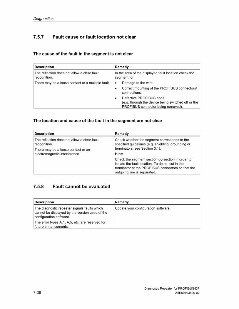
Diagnostics
Diagnostic Repeater for PROFIBUS-DP7-36 A5E00103899-02
7.5.7 Fault cause or fault location not clear
The cause of the fault in the segment is not clear
Description Remedy
The reflection does not allow a clear faultrecognition.There may be a loose contact or a multiple fault.
In the area of the displayed fault location check thesegment for:• Damage to the wire,• Correct mounting of the PROFIBUS connectors/
connections,• Defective PROFIBUS node
(e.g. through the device being switched off or thePROFIBUS connector being removed).
The location and cause of the fault in the segment are not clear
Description Remedy
The reflection does not allow a clear faultrecognition.There may be a loose contact or anelectromagnetic interference.
Check whether the segment corresponds to thespecified guidelines (e.g. shielding, grounding orterminators, see Section 3.1).Hint:Check the segment section-by-section in order toisolate the fault location. To do so, cut in theterminator at the PROFIBUS connectors so that theoutgoing line is separated.
7.5.8 Fault cannot be evaluated
Description Remedy
The diagnostic repeater signals faults whichcannot be displayed by the version used of theconfiguration software.The error types A.1, A.5, etc. are reserved forfuture enhancements.
Update your configuration software.

Diagnostics
Diagnostic Repeater for PROFIBUS-DPA5E00103899-02 7-37
7.5.9 Topology determination not possible
Errors in topology determination with STEP 7 or SFC 103 "DP_TOPOL" aredisplayed in conjunction with the diagnostic repeater with the order number6ES7972-0AB01-0XA0 and thus permit specific errors to be corrected.
• The list of "affected" diagnostic repeaters and the affected segment aredisplayed in STEP 7.
• When an S7 CPU is used with the integrated system function SFC 103"DP_TOPOL", the diagnostic repeater with the lowest address that has an erroris output in the user program.
This display is not possible with COM PROFIBUS or the diagnostic repeater withthe order number 6ES7972-0AB00-0XA0.

Diagnostics
Diagnostic Repeater for PROFIBUS-DP7-38 A5E00103899-02

Diagnostic Repeater for PROFIBUS-DPA5E00103899-02 8-1
8 Technical Specifications
8.1 Standards and approvals
CE marking
Our products fulfill the requirements and protective aims of the following EUguidelines and conform to the harmonized European Standards (EN) which werepublished for programmable logic controllers in the gazettes of the EuropeanUnion:
73/23/EEC "Electrical equipment for use within certain voltage limits" (low-voltageguideline)
89/336/EEC "Electromagnetic compatibility” (EMC guideline)
94/9/EC "Equipment and protective systems for use in explosive atmospheres"(explosion protection guideline)
The EU declarations of conformity are kept available for the correspondingauthorities at:
Siemens AktiengesellschaftBereich Automatisierungs- und AntriebstechnikA&D AS RD 4Postfach 1963
D-92209 Amberg
Underwriters Laboratories Inc. in accordance with
1. UL 508 (Industrial Control Equipment)
2. CSA C22.2 No. 142 (Process Control Equipment)
3. UL 1604 (Hazardous Location)
4. CSA-213 (Hazardous Location)HAZ. LOC.

Technical Specifications
Diagnostic Repeater for PROFIBUS-DP8-2 A5E00103899-02
APPROVED for use inClass I, Division 2, Group A, B, C, D T4A;Class I, Zone 2, Group IIC T4
NoteYou will find the currently valid certificates and approvals on the type plate of thediagnostic repeater.
FM approvalFactory Mutual Research (FM) in accordance withApproval Standard Class Number 3611, 3600, 3810
APPROVED for use inClass I, Division 2, Group A, B, C, D T4AClass I, Zone II, Group IIC T4
In accordance with EN 50021 (Electrical apparatus for potentially explosiveatmospheres; Type of protection "n")
II 3 G EEx nA II T4
Marking for AustraliaThe diagnostic repeater fulfills the requirements of the standardAS/NZS 2064 (Class A).
IEC 61131The diagnostic repeater fulfills the requirements and criteria of the IEC 61131-2standard (Programmable controllers, Part 2: Equipment requirements and tests).
PROFIBUS-DPThe diagnostic repeater fulfills the requirements and criteria of the PROFIBUS-DPV1 standard in accordance with IEC 61158:Ed3 Type 3 orIEC 61784-1:2002 Ed1 CP 3/1.

Technical Specifications
Diagnostic Repeater for PROFIBUS-DPA5E00103899-02 8-3
Approval for shipbuildingClassification organizations:
ABS (American Bureau of Shipping)
BV (Bureau Veritas)
DNV (Det Norske Veritas)
GL (Germanischer Lloyd)
LRS (Lloyds Register of Shipping)
Class NK (Nippon Kaiji Kyokai)
Use in industrial environmentsSIMATIC products are designed for the use in industrial environments.
Requirements Area of application Emitted interference Noise immunity
Industry EN 61000-6-4: 2001 EN 61000-6-2: 2001
Use in residential environmentsIf you use the diagnostic repeater in residential areas, you must ensure it meetsthe requirements of limit value class B in accordance with EN 55011 with regard tothe emission of radio interference.
Suitable measures for meeting the requirements of limit value class B are:
Installation of the diagnostic repeater in grounded switch cabinets/boxes
Use of filters in supply lines
! WarningDamage to persons and material can occur.
In hazardous areas damage to persons and material can occur if you disconnectconnectors while operation is running.
Always de-energize the diagnostic repeater in hazardous areas before separatingconnectors.

Technical Specifications
Diagnostic Repeater for PROFIBUS-DP8-4 A5E00103899-02
8.1.1 Electromagnetic compatibility of the diagnostic repeater
DefinitionThe electromagnetic compatibility is the ability of an electrical device to functionsatisfactorily in its electromagnetic environment without influencing thisenvironment.
The diagnostic repeater also fulfills the requirements of the EMC legislation of theEuropean Union.
The following sections provide information on the immunity to interference and onthe interference suppression.
Pulse-shaped interferencesThe following table shows the electromagnetic compatibility of the diagnosticrepeater with regard to the pulse-shaped interferences. Prerequisite is that thesystem conforms to the specification and guidelines on electrical design.
Pulse-shaped interference Tested with Corresponds to severity
Electrostatic discharge in accordancewith IEC 61000-4-2
8 kV4 kV
3 (air discharge)2 (contact discharge)
Burst pulse (rapid transientdisturbances) to IEC 61000-4-4
2 kV (supply cable)2 kV (signal cable)
3
Surge to IEC 61000-4-5Only with protective elements• Asymmetrical coupling
• Symmetric coupling2 kV (supply cable)2 kV (signal line/data line)1 kV (supply line)1 kV (signal line/data line)
3

Technical Specifications
Diagnostic Repeater for PROFIBUS-DPA5E00103899-02 8-5
Sine-shaped interferenceRF irradiation to the device in accordance with IEC 61000-4-3:
Electromagnetic RF field, amplitude-modulated
- From 80 to 1000 MHz
- 10 V/m
- 80% AM (1 kHz)
Electromagnetic RF field, pulse-modulated
- 900 ±5 MHz
- 10 V/m
- 50% ED
- 200 Hz repetition frequency
RF interference on signal and data cables, etc. to IEC 61000-4-6:
Radio frequency, asymmetrical, amplitude-modulated
- From 0.15 to 80 MHz
- 10 V root-mean-square value, unmodulated
- 80% AM (1 kHz)
- 150 Ohm source impedance
Emission of radio interferencesEmitted interference of electromagnetic fields in accordance with EN55011:Limit value class A, group 1 (measured at a distance of 30 m)
From 20 to 230 MHz < 30 dB (µV/m)Q
From 230 to 1000 MHz < 37 dB (µV/m)Q
Emitted interference via a.c. supply current to EN 55011: Limit value A, Group 1.
From 0.15 to 0.5 MHz < 79 dB (µV)Q, < 66 dB (µV)M
From 0.5 to 5 MHz < 73 dB (µV)Q, < 60 dB (µV)M
From 5 to 30 MHz < 73 dB (µV)Q, < 60 dB (µV)M

Technical Specifications
Diagnostic Repeater for PROFIBUS-DP8-6 A5E00103899-02
8.1.2 Mechanical and climatic ambient conditions for transportationand storage
Diagnostic repeaterThe diagnostic repeater exceeds the requirements of IEC 61131-2 with regard toshipping and storage conditions. The following information applies to diagnosticrepeaters that are transported and stored in the original packaging.
Ambient conditions Range of application Remarks
Free fall 0.3 m –Temperature From -40 to 70°C –Relative humidity From 5 to 95 % Without condensationAir pressure From 1080 to 660 hPa Corresponds to a height of
–1000 to 3500 m
8.1.3 Mechanical and climatic ambient conditions in operation
Conditions of useThe diagnostic repeater is intended for sheltered stationary use. The conditions ofuse exceed the requirements of IEC 61131-2.
The diagnostic repeater fulfills the conditions of use of Class 3C3 to DIN EN 607213-3 (points of use with high traffic density and directly adjacent to industrial plantswith chemical emissions).
LimitationsThe diagnostic repeater may not be used without additional measures
At sites with a high share of ionizing radiation
At sites with severe operation conditions, for example by
- Dust development
- Corrosive vapors or gases.
In plants which require particular monitoring, such as for example
- Elevator plants
- Electrical plants in particularly hazardous areas.
An additional measure for the use can be, for example, the installation of thediagnostic repeater in a cabinet.

Technical Specifications
Diagnostic Repeater for PROFIBUS-DPA5E00103899-02 8-7
Climatic environmental conditionsThe diagnostic repeater may be used under the following ambient conditions:
Ambient conditions Range of application Remarks
Temperature:• Horizontal installation:• Vertical installation:
From 0 to 60 °CFrom 0 to 40 °C
–
Relative humidity From 5 to 95 % Without condensationAir pressure From 1080 to 795 hPa Corresponds to a height of
–1000 to 2000 mPollutant concentration
SO 2 : < 0.5 ppm;relative humidity < 60 %,no condensationH 2 S: < 0.1 ppm;relative humidity < 60 %,no condensation
Test:10 ppm; 4 days
1 ppm; 4 days
Mechanical ambient conditionsThe mechanical ambient conditions of the diagnostic repeater are specified in thefollowing table in the form of sinusoidal oscillation.
Frequency range (Hz) Continuous Occasional
10 <= f <= 58 0.0375 mm amplitude 0.075 mm amplitude58 <= f <= 150 0.5 g constant acceleration 1 g constant acceleration
Reducing oscillationsIf the diagnostic repeater is subject to larger impacts or oscillations, you have totake suitable measures to reduce the acceleration or the amplitude.
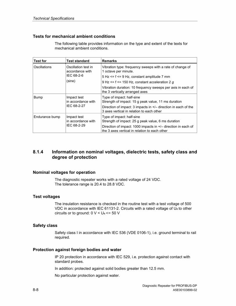
Technical Specifications
Diagnostic Repeater for PROFIBUS-DP8-8 A5E00103899-02
Tests for mechanical ambient conditionsThe following table provides information on the type and extent of the texts formechanical ambient conditions.
Test for Test standard Remarks
Oscillations Oscillation test inaccordance withIEC 68-2-6(sine)
Vibration type: frequency sweeps with a rate of change of1 octave per minute.5 Hz <= f <= 9 Hz, constant amplitude 7 mm9 Hz <= f <= 150 Hz, constant acceleration 2 gVibration duration: 10 frequency sweeps per axis in each ofthe 3 vertically arranged axes
Bump Impact testin accordance withIEC 68-2-27
Type of impact: half-sineStrength of impact: 15 g peak value, 11 ms durationDirection of impact: 3 impacts in +/– direction in each of the3 axes vertical in relation to each other
Endurance bump Impact testin accordance withIEC 68-2-29
Type of impact: half-sineStrength of impact: 25 g peak value, 6 ms durationDirection of impact: 1000 impacts in +/– direction in each ofthe 3 axes vertical in relation to each other
8.1.4 Information on nominal voltages, dielectric tests, safety class anddegree of protection
Nominal voltages for operationThe diagnostic repeater works with a rated voltage of 24 VDC.The tolerance range is 20.4 to 28.8 VDC.
Test voltagesThe insulation resistance is checked in the routine test with a test voltage of 500VDC in accordance with IEC 61131-2. Circuits with a rated voltage of Ue to othercircuits or to ground: 0 V < Ue <= 50 V
Safety classSafety class I in accordance with IEC 536 (VDE 0106-1), i.e. ground terminal to railrequired.
Protection against foreign bodies and waterIP 20 protection in accordance with IEC 529, i.e. protection against contact withstandard probes.
In addition: protected against solid bodies greater than 12.5 mm.
No particular protection against water.

Technical Specifications
Diagnostic Repeater for PROFIBUS-DPA5E00103899-02 8-9
8.2 Technical data of the diagnostic repeater
Dimensions and weight
Dimensions W x H x D (mm)• Without rail• With railWeight
80 x 125 x 66.380 x 125 x 72.2Approximately 300 g
Module-specific dataBus protocolTransfer rate to PROFIBUS-DPMaximum permissible deviation betweenbit-sending and bit-receiving timingMaximum cascading depthRedundant operation
PROFIBUS-DP9.6 kbps to 12 Mbps±0.3% at 9.6 kbps to 500 kbps±0.03% at 1.5 Mbps to 12 Mbps9 diagnostic repeatersNo
Distance information for line diagnosticsResolutionAccuracy
0.5 m±1 m
ClockResolutionAccuracy
10 msTypically 5 s/h slow
Repeater throughput time• Baud rates ≥ 1.5 Mbps• Baud rates < 1.5 MbpsJitter
2.5 TBIT + 153 ns0.5 TBIT +173 ns1T = 1/48 MHz = 20.83 ns
Monitoring function of the clocked PROFIBUS bus systemDP bus cycle (TDP)Tolerance range TDP monitoringTolerance range T DX monitoring
min. 1 ms, max. 32 ms±2 µs±10 µs
Mechanical propertiesMounting possibilitiesDegree of protection
DIN or S7-300 mounting railIP20
Bus cablesTermination system
Suitable cables
Fast Connect (insulation piercing technique,10 connecting cycles possible)SIMATIC NET PROFIBUS cablesSee Appendix A
Cables for power supplyTermination systemSuitable cables• Solid cable• Flexible cable with wire end ferrule• Flexible cable without wire end ferrule
Screw clampingSolid and flexible cables0.14 mm to 2.5 mm2
0.25 mm to 1.5 mm2
0.14 mm to 2.5 mm2

Technical Specifications
Diagnostic Repeater for PROFIBUS-DP8-10 A5E00103899-02
Dimensions and weight
Ambient conditionsOperating temperature• Horizontal installation• Vertical installationStorage temperatureHeat dissipation
0 to 60°C0 to 40°C–40 to +70°CVia housing without forced ventilation
Voltages, currents, potentialsNominal supply voltage• Static limits• Dynamic limits• Reverse polarity protection• Power failure overridingControl-to-load isolation• Between the power supply and the PROFIBUS-
DP• Between segments DP1 and DP2, DP3
and programming device interface• Between segments DP2, DP3
and programming device interfaceInsulation tested withPower consumption at nominal voltage (24V DC)• Without load at programming device interface• Load at programming device interface
(5V/90mA)• Load at programming device interface
(24V/100mA)Power loss of the module
24 VDC1. - 20.4 VDC to 28.8 VDC- 18.5 VDC to 30.2 VDCYes5 ms
Yes
Yes
No500 V DC
150 mA170 mA250 mATypically 4 W
Status, alarms, diagnosisStatus displayAlarmsDiagnostic function• Group error• Bus fault• Repeater function monitoring• 24V voltage supply monitoring• Bus activity programming device• Bus activity segment DP1• Bus activity segment DP2• Bus activity segment DP3• Monitoring segment DP2• Monitoring segment DP3
YesNoneYesRed LED SFRed LED BFGreen LED DRGreen LED ONYellow LED PGYellow LED DP1Yellow LED DP2Yellow LED DP3Red LED ERR DP2Red LED ERR DP3
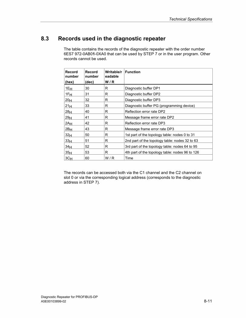
Technical Specifications
Diagnostic Repeater for PROFIBUS-DPA5E00103899-02 8-11
8.3 Records used in the diagnostic repeater
The table contains the records of the diagnostic repeater with the order number6ES7 972-0AB01-0XA0 that can be used by STEP 7 or in the user program. Otherrecords cannot be used.
Recordnumber (hex)
Recordnumber (dec)
Writable/readable W / R
Function
1EH 30 R Diagnostic buffer DP11FH 31 R Diagnostic buffer DP220H 32 R Diagnostic buffer DP321H 33 R Diagnostic buffer PG (programming device)28H 40 R Reflection error rate DP229H 41 R Message frame error rate DP22AH 42 R Reflection error rate DP32BH 43 R Message frame error rate DP332H 50 R 1st part of the topology table: nodes 0 to 3133H 51 R 2nd part of the topology table: nodes 32 to 6334H 52 R 3rd part of the topology table: nodes 64 to 9535H 53 R 4th part of the topology table: nodes 96 to 1263CH 60 W / R Time
The records can be accessed both via the C1 channel and the C2 channel onslot 0 or via the corresponding logical address (corresponds to the diagnosticaddress in STEP 7).
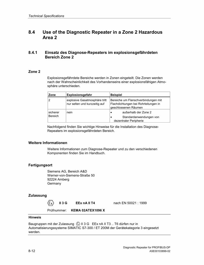
Technical Specifications
Diagnostic Repeater for PROFIBUS-DP8-12 A5E00103899-02
8.4 Use of the Diagnostic Repeater in a Zone 2 HazardousArea 2
8.4.1 Einsatz des Diagnose-Repeaters im explosionsgefährdetenBereich Zone 2
Zone 2Explosionsgefährdete Bereiche werden in Zonen eingeteilt. Die Zonen werdennach der Wahrscheinlichkeit des Vorhandenseins einer explosionsfähigen Atmo-sphäre unterschieden.
Zone Explosionsgefahr Beispiel
2 explosive Gasatmosphäre trittnur selten und kurzzeitig auf
Bereiche um Flanschverbindungen mitFlachdichtungen bei Rohrleitungen ingeschlossenen Räumen
sichererBereich
nein • außerhalb der Zone 2• Standardanwendungen von
dezentraler Peripherie
Nachfolgend finden Sie wichtige Hinweise für die Installation des Diagnose-Repeaters im explosionsgefährdeten Bereich.
Weitere InformationenWeitere Informationen zum Diagnose-Repeater und zu den verschiedenenKomponenten finden Sie im Handbuch.
FertigungsortSiemens AG, Bereich A&DWerner-von-Siemens-Straße 5092224 AmbergGermany
Zulassung
II 3 G EEx nA II T4 nach EN 50021 : 1999
Prüfnummer: KEMA 02ATEX1096 X
Hinweis
Baugruppen mit der Zulassung II 3 G EEx nA II T3 .. T6 dürfen nur inAutomatisierungssysteme SIMATIC S7-300 / ET 200M der Gerätekategorie 3 eingesetztwerden.

Technical Specifications
Diagnostic Repeater for PROFIBUS-DPA5E00103899-02 8-13
InstandhaltungFür eine Reparatur muss die betroffene Komponente an den Fertigungsortgeschickt werden. Nur dort darf die Reparatur durchgeführt werden.
Besondere Bedingungen1. Der Diagnose-Repeater muss in einen Schaltschrank oder ein metallisches
Gehäuse eingebaut werden. Diese müssen mindestens die Schutzart IP 54(nach EN 60529) gewährleisten. Dabei sind die Umgebungsbedingungen zuberücksichtigen, in denen das Gerät installiert wird. Für das Gehäuse musseine Herstellererklärung für Zone 2 vorliegen (gemäß EN 50021).
2. Wenn am Kabel bzw. an der Kabeleinführung dieses Gehäuses unter Betriebs-bedingungen eine Temperatur > 70 °C erreicht wird oder wenn unter Betriebs-bedingungen die Temperatur an der Aderverzweigung > 80 °C sein kann,müssen die Temperatureigenschaften der Kabel mit den tatsächlichgemessenen Temperaturen übereinstimmen.
3. Die eingesetzten Kabeleinführungen müssen der geforderten IP-Schutzart unddem Abschnitt 7.2 (gemäß EN 50021) entsprechen.
4. Alle Geräte, einschließlich Schalter etc., die an den Ein- und Ausgängen vonDiagnose-Repeatern angeschlossen werden, müssen für den ExplosionsschutzTyp EEx nA oder EEx nC genehmigt sein.
5. Es müssen Maßnahmen getroffen werden, dass die Nennspannung durchTransienten um nicht mehr als 40 % überschritten werden kann.
6. Umgebungstemperaturbereich: 0° C bis 60° C
7. Innerhalb des Gehäuses ist an einem nach dem Öffnen gut sichtbaren Platz einSchild mit folgender Warnung anzubringen:WarnungDas Gehäuse darf nur kurze Zeit geöffnet werden, z. B. für visuelle Diagnose.Betätigen Sie dabei keine Schalter, ziehen oder stecken keine Baugruppen undtrennen keine elektrischen Leitungen (Steckverbindungen).Diese Warnung kann unberücksichtigt bleiben, wenn bekannt ist, dass keineexplosionsgefährdete Atmosphäre herrscht.
Liste der zugelassenen BaugruppenDie Liste mit den zugelassenen Baugruppen finden Sie im Internet:
http://www4.ad.siemens.de/view/cs/
unter der Beitrags-ID 13702947.

Technical Specifications
Diagnostic Repeater for PROFIBUS-DP8-14 A5E00103899-02
8.4.2 Use of the Diagnostic Repeater in a Zone 2 Hazardous Area
Zone 2Hazardous areas are divided up into zones. The zones are distinguished accordingto the probability of the existence of an explosive atmosphere. Zone Explosion Hazard Example
2 Explosive gas atmosphereoccurs only seldom and for ashort time
Areas around flange joints with flat gasketsin pipes in enclosed spaces
Safe area No • Outside zone 2• Standard distributed I/O
applications
Below you will find important information on the installation of the diagnosticrepeater in a hazardous area.
Further InformationYou will find further information on the diagnostic repeater and the variouscomponents in the manual.
Production LocationSiemens AG, Bereich A&DWerner-von-Siemens-Straße 5092224 AmbergGermany
Certification
II 3 G EEx nA II T4 to EN 50021 : 1999
Test number: KEMA 02ATEX1096 X
Note
Modules with II 3 G EEx nA II T3 .. T6 certification can only be used inSIMATIC S7-300/ET 200M automation systems belonging to equipmentcategory 3.

Technical Specifications
Diagnostic Repeater for PROFIBUS-DPA5E00103899-02 8-15
MaintenanceIf repair is necessary, the affected component must be sent to the productionlocation. Repairs can only be carried there.
Special Conditions1. The diagnostic repeater must be installed in a cabinet or metal housing. These
must comply with the IP 54 degree of protection as a minimum. Theenvironmental conditions under which the equipment is installed must be takeninto account. There must be a manufacturer’s declaration for zone 2 availablefor the housing (in accordance with EN 50021).
2. If a temperature of > 70 °C is reached in the cable or at the cable entry of thishousing under operating conditions, or if a temperature of > 80 °C can bereached at the junction of the conductors under operating conditions, thetemperature-related properties of the cables must correspond to thetemperatures actually measured.
3. The cable entries used must comply with the required IP degree of protectionand Section 7.2 (in accordance with EN 50021).
4. All devices (including switches, etc.) that are connected to the inputs andoutputs of fail-safe signal modules must be approved for EEx nA or EEx nCexplosion protection.
5. Steps must be taken to ensure that the rated voltage through transients cannotbe exceeded by more than 40 %.
6. Ambient temperature range: 0° C to 60° C
7. A sign containing the following warning must be put up inside the housing in aneasily visible position when the housing is opened:WarningThe housing can only be opened for a short time (e.g. for visual diagnostics). Ifyou do this, do not operate any switches, remove or install any modules ordisconnect any electrical cables (plug-in connections).You can disregard this warning if you know that the atmosphere is nothazardous (i.e. there is no risk of explosion).
List of Approved ModulesYou will find the list of approved modules under the ID 13702947 on the Internet:
http://www4.ad.siemens.de/view/cs/.

Technical Specifications
Diagnostic Repeater for PROFIBUS-DP8-16 A5E00103899-02
8.4.3 Utilisation du répéteur de diagnostic dans un environnement àrisque d'explosion en zone 2
Zone 2Les environnements à risque d'explosion sont répartis en zones. Les zones sedistinguent par la probabilité de présence d'une atmosphère explosive. Zone Risque d’explosion Exemple
2 Formation rare et brève d'uneatmosphère gazeuse explosive
Environnement de raccords à joints platsdans le cas de conduites dans des locauxfermés
Zone sûre Non • A l'extérieur de la zone 2• Utilisation standard de périphérie
décentralisée
Vous trouverez ci-après des remarques importantes pour l'installation du répéteurde diagnostic dans un environnement présentant un risque d'explosion.
Informations complémentairesDes informations complémentaires sur le répéteur de diagnostic et les diversescomposantes se trouvent dans le manuel.
Lieu de productionSiemens AG, Bereich A&DWerner-von-Siemens-Straße 5092224 AmbergGermany
Homologation
II 3 G EEx nA II T4 selon EN 50021 : 1999
Numéro de contrôle : KEMA 02ATEX1096 X
Nota
Les modules homologués II 3 G EEx nA II T3 .. T6 ne peuvent être utilisésque dans des automates SIMATIC S7-300 / ET 200M de catégorie 3.

Technical Specifications
Diagnostic Repeater for PROFIBUS-DPA5E00103899-02 8-17
EntretienSi une réparation est nécessaire, la composante concernée doit être expédiée aulieu de production. La réparation ne doit être effectuée qu'en ce lieu.
Conditions particulières1. Le répéteur de diagnostic doit être installé dans une armoire ou un boîtier
métallique. Ceux-ci doivent assurer au moins l'indice de protection IP 54. Il fautalors tenir compte des conditions d'environnement dans lesquelles l'appareilest installé. Le boîtier doit faire l’objet d’une déclaration de conformité dufabricant pour la zone 2 (selon EN 50021).
2. Si dans les conditions d’exploitation, une température > 70 °C est atteinte auniveau du câble ou de l’entrée du câble dans ce boîtier, ou bien si latempérature au niveau de la dérivation des conducteurs peut être > 80 °C, lescapacités de résistance thermique des câbles doivent corespondre auxtempératures effectivement mesurées.
3. Les entrées de câbles utilisées doivent avoir le niveau de protection IP exigé etêtre conformes au paragraphe 7.2 (selon EN 50021).
4. Tous les appareillages (y compris les interrupteurs, etc.) raccordés aux entréeset sorties de modules de signaux à sécurité intrinsèque doivent êtrehomologués pour la protection antidéflagrante type EEx nA ou EEx nC.
5. Il faut prendre des mesures pour que la tension nominale ne puisse pas êtredépassée de plus de 40% sous l’influence de transitoires.
6. Plage de température ambiante : 0° C à 60° C
7. A l’intérieur du boîtier, il faut placer, à un endroit bien visible après ouverture,une plaquette comportant l’avertissement suivant :AvertissementOuvir le boîtier le moins longtemps possible, par exemple pour effectuer undiagnostic visuel. Ce faisant, n’actionnez aucun commutateur, ne déconnectezaucun module et ne débanchez pas de câbles électriques (connexions).Le respect de cet avertissement n’est pas impératif s’il est certain quel’environnement ne présente pas de risque d’explosion.
Liste des modules homologuésVous trouverez sur Internet la liste des modules homologués :
http://www4.ad.siemens.de/view/cs/
référence ID 13702947.
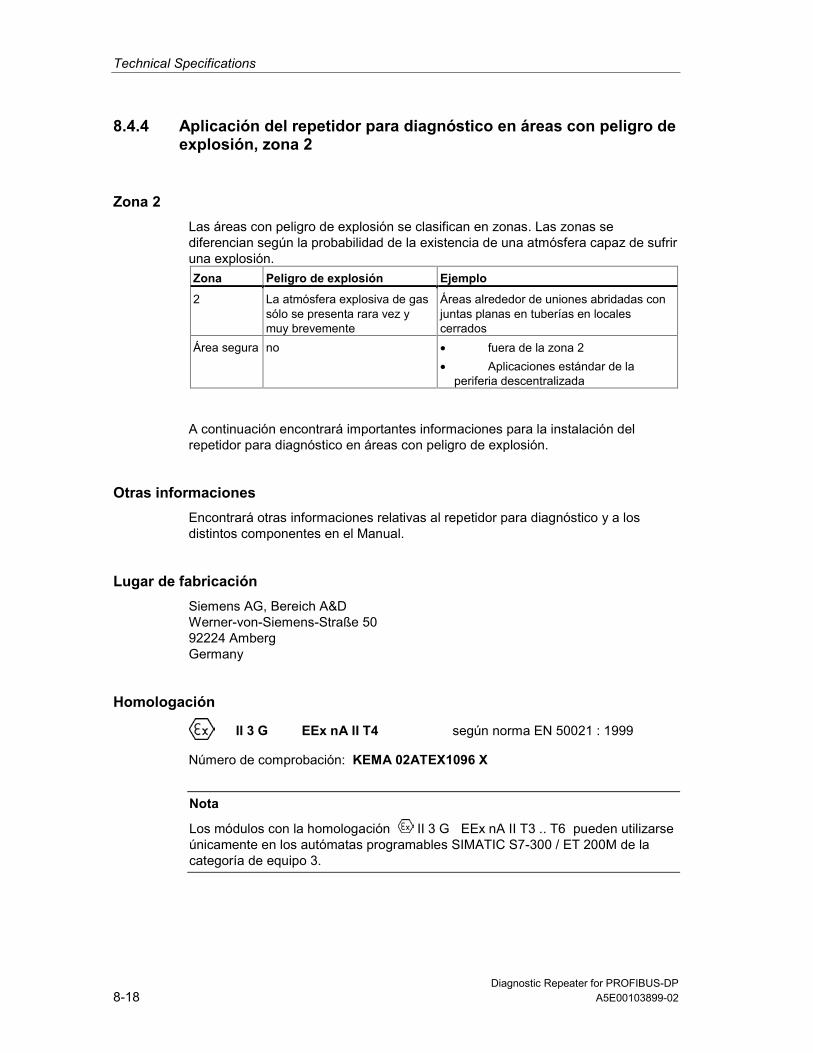
Technical Specifications
Diagnostic Repeater for PROFIBUS-DP8-18 A5E00103899-02
8.4.4 Aplicación del repetidor para diagnóstico en áreas con peligro deexplosión, zona 2
Zona 2Las áreas con peligro de explosión se clasifican en zonas. Las zonas sediferencian según la probabilidad de la existencia de una atmósfera capaz de sufriruna explosión. Zona Peligro de explosión Ejemplo
2 La atmósfera explosiva de gassólo se presenta rara vez ymuy brevemente
Áreas alrededor de uniones abridadas conjuntas planas en tuberías en localescerrados
Área segura no • fuera de la zona 2• Aplicaciones estándar de la
periferia descentralizada
A continuación encontrará importantes informaciones para la instalación delrepetidor para diagnóstico en áreas con peligro de explosión.
Otras informacionesEncontrará otras informaciones relativas al repetidor para diagnóstico y a losdistintos componentes en el Manual.
Lugar de fabricaciónSiemens AG, Bereich A&DWerner-von-Siemens-Straße 5092224 AmbergGermany
Homologación
II 3 G EEx nA II T4 según norma EN 50021 : 1999
Número de comprobación: KEMA 02ATEX1096 X
Nota
Los módulos con la homologación II 3 G EEx nA II T3 .. T6 pueden utilizarseúnicamente en los autómatas programables SIMATIC S7-300 / ET 200M de lacategoría de equipo 3.

Technical Specifications
Diagnostic Repeater for PROFIBUS-DPA5E00103899-02 8-19
MantenimientoPara una reparación se ha de remitir el componente afectado al lugar defabricación. Sólo allí se puede realizar la reparación.
Condiciones especiales1. El repetidor para diagnóstico se ha de montar en un armario eléctrico de
distribución o en una carcasa metálica. Éstos deben garantizar como mínimoel grado de protección IP 54. Para ello se han de tener en cuenta lascondiciones ambientales, en las cuales se instala el equipo. La caja deberácontar con una declaración del fabricante para la zona 2 (conforme aEN 50021).
2. Si durante la operación se alcanzara una temperatura > 70° C en el cable o laentrada de cables de esta caja o bien una temperatura > 80° C en labifurcación de hilos, deberán adaptarse las propiedades térmicas de los cablesa las temperaturas medidas efectivamente.
3. Las entradas de cable utilizadas deben cumplir el grado de protección IPexigido y lo expuesto en el apartado 7.2 (conforme a EN 50021).
4. Todos los dispositivos –inclusive interruptores, etc.– conectados a las entradasy salidas de módulos de señales de alta disponibilidad deben estarhomologados para la protección contra explosiones del tipo EEx nA o EEx nC.
5. Es necesario adoptar las medidas necesarias para evitar que la tensiónnominal pueda rebasar en más del 40 % debido a efectos transitorios.
6. Margen de temperatura ambiente: 0° C hasta 60° C
7. Dentro de la caja deberá colocarse en un lugar perfectamente visible tras suapertura un rótulo con la siguiente advertencia:PrecauciónAbrir la caja sólo brevemente, p.ej. para el diagnóstico visual. Durante estetiempo Ud. no deberá activar ningún interruptor, desenchufar o enchufarmódulos ni separar conductores eléctricos (conexiones enchufables).Esta advertencia puede ignorarse si Ud. sabe que en la atmósfera existente nohay peligro de explosión.
Lista de los módulos homologadosEn la internet hallará Ud. una lista con los módulos homologados:
http://www4.ad.siemens.de/view/cs/
bajo el ID de asignación 13702947.

Technical Specifications
Diagnostic Repeater for PROFIBUS-DP8-20 A5E00103899-02
8.4.5 Impiego del repeater di diagnostica nell’area a pericolo diesplosione zona 2
Zona 2Le aree a pericolo di esplosione vengono suddivise in zone. Le zone vengonodistinte secondo la probabilità della presenza di un'atmosfera esplosiva. Zona Pericolo di esplosione Esempio
2 L’atmosfera esplosiva sipresente solo raramente ebrevemente
Aree intorno a collegamenti a flange conguarnizioni piatte nelle condotte in ambientichiusi
Area sicura No • Al di fuori della zona 2• Applicazioni standard di periferia
decentrata
Qui di seguito sono riportate delle avvertenze importanti per l'installazione delrepeater di diagnostica nell'area a pericolo di esplosione.
Ulteriori informazioniUlteriori informazioni sul repeater di diagnostica e sui diversi componenti si trovanonel manuale.
Luogo di produzioneSiemens AG, Bereich A&DWerner-von-Siemens-Straße 5092224 AmbergGermany
Autorizzazione
II 3 G EEx nA II T4 secondo EN 50021 : 1999
Numero di controllo: KEMA 02ATEX1096 X
Avvertenza
Le unità con l'autorizzazione II 3 G EEx nA II T3 .. T6 possono essereimpiegate solo nei sistemi di controllori programmabili SIMATIC S7-300 / ET 200Mdella categoria di apparecchiature 3.

Technical Specifications
Diagnostic Repeater for PROFIBUS-DPA5E00103899-02 8-21
ManutenzionePer una riparazione, il componente interessato deve essere inviato al luogo diproduzione. La riparazione può essere effettuata solo lì.
Condizioni particolari1. Il repeater di diagnostica deve essere montata in un armadio elettrico o in un
contenitore metallico. Questi devono assicurare almeno il tipo di protezioneIP 54. In questo caso bisogna tenere conto delle condizioni ambientali nellequali l'apparecchiatura viene installata. Per il contenitore deve essere presenteuna dichiarazione del costruttore per la zona 2 (secondo EN 50021).
2. Se nei cavi o nel loro punto di ingresso in questo contenitore viene raggiunta incondizioni di esercizio una temperatura > 70 °C o se in condizioni di eserciziola temperatura nella derivazione dei fili può essere > 80 °C, le caratteristiche ditemperatura dei cavi devono essere conformi alla temperatura effettivamentemisurata.
3. Gli ingressi dei cavi usati devono essere conformi al tipo di protezione richiestoe alla sezione 7.2 (secondo EN 50021).
4. Tutte le apparecchiature, inclusi interruttori, ecc. che vengono collegati agliingressi/uscite di unità di segnale ad elevata sicurezza, devono essere statiomologati per la protezione da esplosione tipo EEx nA o EEx nC.
5. Devono essere prese delle misure per evitare che la tensione nominale possaessere superata per più del 40% da parte di transienti.
6. Campo termico ambientale: da 0° C a 60° C
7. All’interno del contenitore va apportata, in un luogo ben visibile dopo l’apertura,una targhetta con il seguente avvertimento:AttenzioneIl contenitore può rimanere aperto solo per breve tempo, ad esempio per unadiagnostica a vista. In tal caso non azionare alcun interruttore, nondisinnestare o innestare unità e non staccare connessioni elettriche(connettori).Non è necessario tenere conto di questo avvertimento se è noto che non c’èun’atmosfera a rischio di esplosione.
Elenco delle unità abilitateLa lista con le unità omologate si trova in Internet al sito:
http://www4.ad.siemens.de/view/cs/
all’ID di voce 13702947.

Technical Specifications
Diagnostic Repeater for PROFIBUS-DP8-22 A5E00103899-02
8.4.6 Gebruik van de diagnose-repeater in het explosieve gebiedzone 2
Zone 2Explosieve gebieden worden ingedeeld in zones. Bij de zones wordtonderscheiden volgens de waarschijnlijkheid van de aanwezigheid van eenexplosieve atmosfeer. Zone Explosion Hazard Example
2 Een explosieve gasatmosfeertreedt maar zelden op en voorkorte duur
Gebieden rond flensverbindingen metpakkingen bij buisleidingen in geslotenvertrekken
Veiliggebied
neen • Buiten de zone 2• Standaardtoepassingen van
decentrale periferie
Hierna vindt u belangrijke aanwijzingen voor de installatie van de diagnose-repeater in een explosief gebied.
Verdere informatieIn het handboek vindt u verdere informatie over de diagnose-repeater en deverschillende componenten.
ProductieplaatsSiemens AG, Bereich A&DWerner-von-Siemens-Strasse 5092224 AmbergGermany
Vergunning
II 3 G EEx nA II T4 conform EN 50021 : 1999
Keuringsnummer: KEMA 02ATEX1096 X
Opmerking
Modulen met de vergunning II 3 G EEx nA II T3 .. T6 mogen slechts wordengebruikt in automatiseringssystemen SIMATIC S7-300 / ET 200M van deapparaatcategorie 3.

Technical Specifications
Diagnostic Repeater for PROFIBUS-DPA5E00103899-02 8-23
InstandhoudingDe te herstellen component moet voor reparatie naar de plaats van vervaardigingworden gestuurd. Alleen daar mag de reparatie worden uitgevoerd.
Speciale voorwaarden1. De diagnose-repeater moet worden ingebouwd in een schakelkast of in een
behuizing van metaal. Deze moeten minstens de veiligheidsgraad IP 54waarborgen. Hierbij dient rekening te worden gehouden met deomgevingsvoorwaarden waarin het apparaat wordt geïnstalleerd. Voor debehuizing dient een verklaring van de fabrikant voor zone 2 te wordeningediend (volgens EN 50021).
2. Als aan de kabel of aan de kabelinvoering van deze behuizing onderbedrijfsomstandigheden een temperatuur wordt bereikt > 70 °C of als onderbedrijfsomstandigheden de temperatuur aan de adervertakking > 80 °C kanzijn, moeten de temperatuureigenschappen van de kabel overeenstemmenmet de werkelijk gemeten temperaturen.
3. De aangebrachte kabelinvoeringen moeten de vereiste IP-veiligheidsgraadhebben en in overeenstemming zijn met alinea 7.2 (volgens EN 50021).
4. Alle apparaten, schakelaars enz. inbegrepen, die worden aangesloten op dein- en uitgangen van tegen fouten beveiligde signaalmodulen, moeten zijngoedgekeurd voor de explosiebeveiliging type EEx nA of EEx nC.
5. Er dienen maatregelen te worden getroffen, zodat de nominale spanning doortransiënten met niet meer dan 40 % kan worden overschreden.
6. Omgevingstemperatuurbereik: 0° C tot 60° C
7. Binnen de behuizing dient op een na het openen goed zichtbare plaats eenbord te worden aangebracht met de volgende waarschuwing:WaarschuwingDe behuizing mag slechts voor korte tijd worden geopend, bijv. voor eenvisuele diagnose. Bedien hierbij geen schakelaar, trek of steek geen modulenen ontkoppel geen elektrische leidingen (steekverbindingen).Deze waarschuwing kan buiten beschouwing blijven, indien bekend is dat ergeen explosieve atmosfeer heerst.
Lijst van de toegelaten modulenDe lijst met de toegelaten modulen vindt u in het internet:
http://www4.ad.siemens.de/view/cs/
onder de bijdrage-ID 13702947.

Technical Specifications
Diagnostic Repeater for PROFIBUS-DP8-24 A5E00103899-02
8.4.7 Brug af diagnose-repeateren i det eksplosionsfarlige områdezone 2
Zone 2Eksplosionsfarlige områder inddeles i zoner. Zonerne adskiller sig indbyrdes efterhvor sandsynligt det er, at der er en eksplosiv atmosfære. Zone Eksplosionsfare Eksempel
2 Eksplosiv gasatmosfæreoptræder kun sjældent og varerkort
Områder rundt om flangeforbindelser medflade pakninger ved rørledninger i lukkederum
Sikkertområde
Nej • Uden for zone 2• Standardanvendelser decentral
periferi
I det følgende findes vigtige henvisninger vedr. installation af diagnose-repeateren ieksplosionsfarligt område.
Yderligere informationerYderligere informationer om diagnose-repeateren og de forskellige komponenterfindes i manualen.
ProduktionsstedSiemens AG, Bereich A&DWerner-von-Siemens-Straße 5092224 AmbergGermany
Godkendelse
II 3 G EEx nA II T4 efter EN 50021 : 1999
Kontrolnummer: KEMA 02ATEX1096 X
Bemærk
Komponenter med godkendelsen II 3 G EEx nA II T3 .. T6 må kun monteres iautomatiseringssystemer SIMATIC S7-300 / ET 200M - udstyrskategori 3.
Technical Specifications
Diagnostic Repeater for PROFIBUS-DPA5E00103899-02 8-25
VedligeholdelseSkal den pågældende komponent repareres, bedes De sende den tilproduktionsstedet. Reparation må kun udføres der.
Særlige betingelser1. Diagnose-repeateren skal monteres i et kontrolskab eller et metalkabinet.
Disse skal mindst kunne sikre beskyttelsesklasse IP 54. I denne forbindelseskal der tages højde for de omgivelsestemperaturer, i hvilke udstyret erinstalleret. Der skal være udarbejdet en erklæring fra fabrikanten for kabinettetfor zone 2 (iht. EN 50021).
2. Hvis kablet eller kabelindføringen på dette hus når op på en temperatur på> 70 °C under driftsbetingelser eller hvis temperaturen på åreforegreningenkan være > 80 °C under driftsbetingelser, skal kablernestemperaturegenskaber stemme overens med de temperaturer, der rent faktiskmåles.
3. De benyttede kabelindføringer skal være i overensstemmelse med denkrævede IP-beskyttelsestype og afsnittet 7.2 (iht. EN 50021).
4. Alle apparater, inkl. kontakter osv., der forbindes med ind- og udgangene tilfejlsikre signalkomponenter, skal være godkendt til eksplosionsbeskyttelse aftype EEx nA eller EEx nC.
5. Der skal træffes foranstaltninger, der sørger for, at den nominelle spænding viatransienter ikke kan overskrides mere end 40 %.
6. Omgivelsestemperaturområde: 0° C til 60° C
7. I kabinettet skal der anbringes et skilt, der skal kunne ses, når kabinettetåbnes. Dette skilt skal have følgende advarsel:AdvarselKabinettet må kun åbnes i kort tid, f.eks. til visuel diagnose. Tryk i denneforbindelse ikke på kontakter, træk eller isæt ikke komponenter og afbryd ikkeelektriske ledninger (stikforbindelser).Denne advarsel skal der ikke tages højde for, hvis man ved, at der ikke ernogen eksplosionsfarlig atmosfære.
Liste over godkendte komponenterListen med de godkendte komponenter findes på internettet:
http://www4.ad.siemens.de/view/cs/
under bidrags-ID 13702947.

Technical Specifications
Diagnostic Repeater for PROFIBUS-DP8-26 A5E00103899-02
8.4.8 Diagnoosi-toistimen käyttö räjähdysvaarannetuilla alueilla,vyöhyke 2
Vyöhyke 2Räjähdysvaarannetut alueet jaetaan vyöhykkeisiin. Vyöhykkeet erotellaanräjähdyskelpoisen ilmakehän olemassa olon todennäköisyyden mukaan. Vyöhyke Räjähdysvaara Esimerkki
2 Räjähtävä kaasuilmakehäilmaantuu vain harvoin jalyhytaikaisesti
Alueet putkistojen lattatiivisteillä varustuillalaippaliitoksilla suljetuissa tiloissa
turvallinenalue
ei • vyöhykkeen 2 ulkopuolella• Hajautetun ulkopiirin
vakiosovellukset
Seuraavasta löydätte tärkeitä ohjeita diagnoosi-toistimen asennukseenräjähdysvaarannetuilla alueilla.
LisätietojaLisätietoja diagnoosi-toistimeen ja erilaisiin komponentteihin löydätte ohjekirjasta.
ValmistuspaikkaSiemens AG, Bereich A&DWerner-von-Siemens-Straße 5092224 AmbergGermany
Hyväksyntä
II 3 G EEx nA II T4 EN 50021 mukaan: 1999
Tarkastusnumero: KEMA 02ATEX1096 X
Ohje
Rakenneryhmät hyväksynnän II 3 G EEx nA II T3 .. T6 kanssa saadaankäyttää ainoastaan laitekategorian 3 automatisointijärjestelmissä SIMATIC S7-300 /ET 200M.

Technical Specifications
Diagnostic Repeater for PROFIBUS-DPA5E00103899-02 8-27
KunnossapitoKorjausta varten täytyy kyseinen komponentti lähettää valmistuspaikkaan. Korjausvoidaan suorittaa ainoastaan siellä.
Erityiset vaatimukset1. Diagnoosi-toistin täytyy asentaa kytkentäkaappiin tai metalliseen koteloon.
Näiden täytyy olla vähintään kotelointiluokan IP 54 mukaisia. Tällöin onhuomioitava ympäristöolosuhteet, johon laite asennetaan. Kotelolle täytyy ollavalmistajaselvitys vyöhykettä 2 varten (EN 50021 mukaan).
2. Kun johdolla tai tämän kotelon johdon sisäänviennillä saavutetaan > 70 °Clämpötila tai kun käyttöolosuhteissa lämpötila voi piuhajaotuksella olla > 80 °C,täytyy johdon lämpötilaominaisuuksien vastata todellisesti mitattuja lämpötiloja.
3. Käytettyjen johtojen sisäänohjauksien täytyy olla vaaditun IP-kotelointiluokan jakohdan 7.2 (EN 50021 mukaan) mukaisia.
4. Kaikkien laitteiden, kytkimet jne. mukaan lukien, jotka liitetään virheiltäsuojattujen signaalirakenneryhmien tuloille ja lähdöille, täytyy olla hyväksyttyjätyypin EEx nA tai EEx nC räjähdyssuojausta varten.
5. Toimenpiteet täytyy suorittaa, ettei nimellisjännite voi transienttien kautta ylittyäenemmän kuin 40 %.
6. Ympäristölämpötila-alue: 0° C ... 60° C
7. Kotelon sisälle, avauksen jälkeen näkyvälle paikalle, on kiinnitettävä kilpi,jossa on seuraava varoitus:VaroitusKotelo saadaan avata ainoastaan lyhyeksi ajaksi, esim. visuaalista diagnoosiavarten. Älä tällöin käytä mitään kytkimiä, vedä tai liitä mitään rakenneryhmiä,äläkä erota mitään sähköjohtoja (pistoliittimiä).Tätä varoitusta ei tarvitse huomioida, kun on tiedossa, että minkäänlaistaräjähdysvaarannettua ilmakehää ei ole olemassa.
Hyväksyttyjen rakenneryhmien listaLista hyväksiytyistä rakennesarjoista löytyy internetistä osoitteesta:
http://www4.ad.siemens.de/view/cs/
käyttäjätunnuksella 13702947.

Technical Specifications
Diagnostic Repeater for PROFIBUS-DP8-28 A5E00103899-02
8.4.9 Användning av diagnosrepeater i explosionsriskområde zon 2
Zon 2Explosionsriskområden delas in i zoner. Zonerna delas in enligt sannolikheten atten atmosfär med explosionsfara föreligger. Zon Explosionsfara Exempel
2 Explosiv gasatmosfär uppstårendast sällan eller kortvarigt
Områden kring flänsförbindelser medpackningar vid rörledningar i slutnautrymmen
Säkertområde
Nej • Utanför zon 2• Standardanvändning av decentral
periferi
Nedan följer viktiga anvisningar om installationen av diagnosrepeaternskomponenter i ett explosionsriskområde.
Ytterligare informationYtterligare information om diagnosrepeatern finner du i handboken.
TillverkningsortSiemens AG, Bereich A&DWerner-von-Siemens-Straße 5092224 AmbergGermany
Godkännande
II 3 G EEx nA II T4 enligt EN 50021 : 1999
Kontrollnummer: KEMA 02ATEX1096 X
Anvisning
Komponentgrupper med godkännande II 3 G EEx nA II T3 .. T6 får endastanvändas i automatiseringssystemen SIMATIC S7-300 / ET°200M frånapparatgrupp 3.

Technical Specifications
Diagnostic Repeater for PROFIBUS-DPA5E00103899-02 8-29
UnderhållVid reparation måste den aktuella komponenten insändas till tillverkaren.Reparationer får endast genomföras där.
Särskilda villkor1. Diagnosrepeatern måste monteras i ett kopplingsskåp eller metallhus. Dessa
måste minst vara av skyddsklass IP 54. Därvid ska omgivningsvillkoren därenheten installeras beaktas. För kåpan måste en tillverkardeklaration för zon 2föreligga (enligt EN 50021).
2. Om en temperatur på > 70°C uppnås vid husets kabel resp kabelinföring underdriftvillkor eller om temperaturen vid trådförgreningen kan vara > 80°C underdriftvillkor, måste kabelns temperaturegenskaper överensstämma med denverkligen uppmätta temperaturen.
3. De använda kabelinföringarna måste uppfylla kraven i det krävda IP-skyddsutförandet och i avsnitt 7.2 (enligt EN 50021).
4. Alla apparater, inklusive brytare osv, som ansluts till felsäkrade signalenhetersin- och utgångar, måste vara godkända för explosionsskydd av typ EEx nAeller EEx nC.
5. Åtgärder måste vidtas så, att märkspänningen ej kan överskridas med mer än40°% genom transienter.
6. Omgivningstemperatur: 0° C till 60° C
7. När huset öppnats ska en skylt med följande varning monteras på ett tydligtsynligt ställe huset:VarningHuset får endast öppnas under kort tid, t ex för visuell diagnos. Använd därvidinga brytare, lossa eller anslut inga enheter och frånskilj inga elektriskaledningar (insticksanslutningar).Ingen hänsyn måste tas till denna varning om det är säkert att det inte rådernågon explosionsfarlig atmosfär.
Lista över godkända komponentgrupperLista över godkända enheter återfinns i Internet:
http://www4.ad.siemens.de/view/cs/
under bidrags-ID 13702947.

Technical Specifications
Diagnostic Repeater for PROFIBUS-DP8-30 A5E00103899-02
8.4.10 Uso do Diagnose-Repeaters em área exposta ao perigo deexplosão, zona 2
Zona 2As áreas expostas ao perigo de explosão são divididas em zonas. As zonas sãodiferenciadas de acordo com a probabilidade da existência de uma atmosferaexplosiva. Zona Perigo de explosão Exemplo
2 Só raramente e por um breveperíodo de tempo surgematmosferas explosivas
Áreas em torno de ligações flangeadas comvedações chatas em tubulações emrecintos fechados
Área segura não • fora da zona 2• Aplicações descentralizadas de
periferia descentralizada
A seguir, encontrará avisos importantes para a instalação do repetidor paradiagnóstico em área exposta ao perigo de explosão.
Mais informaçõesPara obter mais informações sobre o Diagnose-Repeater e sobre os diversoscomponentes, consulte o manual.
Local de produçãoSiemens AG, Bereich A&DWerner-von-Siemens-Straße 5092224 AmbergGermany
Licença
II 3 G EEx nA II T4 seg. EN 50021 : 1999
Número de ensaio: KEMA 02ATEX1096 X
Aviso
Componentes com a licença II 3 G EEx nA II T3 .. T6 só podem seraplicados em sistemas de automação SIMATIC S7-300 / ET 200M da categoria deaparelho 3.

Technical Specifications
Diagnostic Repeater for PROFIBUS-DPA5E00103899-02 8-31
ReparoOs componentes em questão devem ser remetidos para o local de produção a fimde que seja realizado o reparo. Apenas lá deve ser efetuado o reparo.
Condições especiais1. O repetidor para diagnóstico deve ser montado em um armário de distribuição
ou em uma caixa metálica. Estes devem garantir no mínimo o tipo de proteçãoIP 54. Durante este trabalho deverão ser levados em consideração ascondições locais, nas quais o aparelho será instalado. Para a caixa deverá serapresentada uma declaração do fabricante para a zona 2 (de acordo comEN 50021).
2. Caso no cabo ou na entrada do cabo desta carcaça sob as condiçõesoperacionais seja atingida uma temperatura de > 70 °C, ou caso sobcondições operacionais a temperatura na ramificação do fio poderá atingir> 80 °C, as caraterísticas de temperatura deverão corresponder àstemperaturas realmente medidas.
3. As entradas de cabo utilizadas devem corresponder ao tipo exigido deproteção IP e à seção 7.2 (de acordo com o EN 50021).
4. Todos os aparelhos, inclusive as chaves, etc., que estejam conectadas ementradas e saídas de módulos de sinais protegidos contra erro, devem possuira licença para a proteção de explosão do tipo EEx nA ou EEx nC.
5. Precisam ser tomadas medidas para que a tensão nominal através detransitórios não possa ser ultrapassada em mais que 40 %.
6. Área de temperatura ambiente: 0° C até 60° C
7. No âmbito da carcaça deve ser colocada, após a abertura, em um ponto bemvisível uma placa com a seguinte advertência:AdvertênciaA carcaça deve ser aberta apenas por um breve período de tempo, por ex.para diagnóstico visual. Não acione nenhum interruptor, não retire ou conectenenhum módulo e não separe nenhum fio elétrico (ligações de tomada).Esta advertência poderá ser ignorada caso se saiba que não há nenhumaatmosfera sujeita ao perigo de explosão.
Lista dos componentes autorizadosA lista com os módulos autorizados encontram-se na Internet:
http://www4.ad.siemens.de/view/cs/
sob o número de ID 13702947.

Technical Specifications
Diagnostic Repeater for PROFIBUS-DP8-32 A5E00103899-02
8.4.11 , 2
2 .
. 2 ••••••••• •••••••••• ••••••
••••••••••••• •••• •••••• ••• ••• •••••••••••••• ••••••••
•••••••• •••• ••• •••••••••• ••••••••• •• ••••••••• •••••••••••• •• ••••••••• ••••••
••••••• ••••••• ••• • ••••• ••• ••••• 2• ••••••• ••••••••• •••••••••••••• •••••••••••
.
Siemens AG, Bereich A&DWerner-von-Siemens-Straße 5092224 AmbergGermany
II 3 G EEx nA II T4
EN 50021 : 1999
: KEMA 02ATEX1096 X
II 3 G EEx nA II T3 .. T6 SIMATIC S7-300 / ET 200M
3.

Technical Specifications
Diagnostic Repeater for PROFIBUS-DPA5E00103899-02 8-33
.
1.
2
EN 50021).
2. 70 °C
80 °C, .
3. IP
EN 50021).
4.
EEx nAEEx nC.
5. %.
6. C
7.
http://www4.ad.siemens.de/view/cs/

Technical Specifications
Diagnostic Repeater for PROFIBUS-DP8-34 A5E00103899-02

Diagnostic Repeater for PROFIBUS-DPA5E00103899-02 A-1
A Order Numbers
Diagnostic repeater and accessories
Designation Order number
Diagnostic repeater 6ES7972-0AB01-0XA0SIMATIC S5/S7 connecting cable for 12 MbpsProgramming device connection to PROFIBUS-DP(active cable)
6ES7901-4BD00-0XA0
Fast-Connect stripping tool 6GK1905-6AA00BT200 Bus physics testing device for PROFIBUS-DP 6ES7181-0AA01-0AA0
PROFIBUS-DP bus connector
Designation Order number
PROFIBUS-DP bus connector (12 Mbps) 6ES7972-0BA12-0XA0PROFIBUS-DP bus connector (12 Mbps) 6ES7972-0BB12-0XA0PROFIBUS-DP bus connector (12 Mbps) 6ES7972-0BA41-0XA0PROFIBUS-DP bus connector (12 Mbps) 6ES7972-0BB41-0XA0PROFIBUS-DP bus connector (12 Mbps)Without programming device connector
6ES7972-0BA50-0XA0
PROFIBUS-DP bus connector (12 Mbps)With programming device connector
6ES7972-0BB50-0XA0
PROFIBUS-DP bus connector (12 Mbps)(with straight outgoing feeder)
6GK1500-0FC00
NoteIf you are using other connectors, the design guidelines for the diagnostic repeaterrequire them to meet particular requirements (see Section 3.1.3).

Order Numbers
Diagnostic Repeater for PROFIBUS-DPA-2 A5E00103899-02
SIMATIC NET PROFIBUS cablesThe table below shows the SIMATIC NET PROFIBUS cables that can be used inconjunction with the diagnostic repeater or are not permissible as well as thepermissible line lengths in segments DP2 and DP3.
Designation Order number Maximalpermissible linelength
FC Standard Cable 6XV1 830-0EH10 100 mFC FRNC Cable 6XV1 830-0LH10 100 mFC Food Cable 6XV1 830-0GH10 100 mFC Robust Cable 6XV1 830-0JH10 100 mFC Underground Cable 1 6XV1 830-3FH10 100 mFC Trailing Cable 6XV1 830-3EH10 80 mFestoon Cable 2 6XV1 830 -3GH10 80 mFlexible Cable 2 6XV1830-0PH10 80 mSIENOPYRFR shipboard cable3 6XV1830-0MH10 80 mFC Process Cable for IEC 61158-2 6XV1 830-5EH10
6XV1 830-5FH10Not permissible
Cable for festoon attachment 6XV1 830-3CH10 Not permissible1 Outside diameter > 8 mm, connection to the diagnostic repeater only possible after
removal of the outer sheath.
2 Direction connection possible to the diagnostic repeater.
3 Convert to a FastConnect cable.
NoteIf you are using other cables, the design guidelines for the diagnostic repeaterrequire them to meet particular requirements (see Section 3.1.3).
Manuals
Designation Order number
Diagnostic Repeater for PROFIBUS-DP German Manual 6ES7 972-0AB00-8AA0Diagnostic Repeater for PROFIBUS-DP English Manual 6ES7 972-0AB00-8BA0Diagnostic Repeater for PROFIBUS-DP French Manual 6ES7 972-0AB00-8CA0SIMATIC NET PROFIBUS Networks 6GK1970-5CA20-0AA1Programming with STEP 7 V5.1 6ES7 810-4CA05-8BA0SIMATIC Manual Collection 08/2002 6ES7 998-8XC01-8YE0

Diagnostic Repeater for PROFIBUS-DPA5E00103899-02 B-1
B Dimension Drawings
Diagnostic repeater
DIAGNOSTIC REPEATER
DP3A3/B3
SEGMENT DP3OFF ON
TERMINATOR DP1OFF ON
X1PG
DP2A2/B2
DP1A1/B1 A1´/B1´
SFBFDRON
PGDP1DP2DP3
ERR DP2ERR DP3
BUSADDRESS
125
8066,3

Dimension Drawings
Diagnostic Repeater for PROFIBUS-DPB-2 A5E00103899-02

Diagnostic Repeater for PROFIBUS-DPA5E00103899-02 C-1
C User Questions
C.1 Topology and fault point determination
Is the topology determined automatically?When an S7 CPU is used with the integrated system function SFC 103"DP_TOPOL", the topology can be determined automatically in the user program.
When any other CPU is used, the topology must be determined by the user usingSTEP 7 or COM PROFIBUS after any change to the plant. To do so use the menucommands
• PLC > PROFIBUS > Prepare Line Diagnostics in STEP 7 or
• Service > Prepare Line Diagnostics in COM PROFIBUS.
Can I read out the topology table?In the case of diagnostic repeaters with the order number 6ES7 972-0AB01-0XA0you can read out the topology table.If you do not want to use the tabular rather than the graphical topology display,choose the following menu command in STEP 7 View > Topology table.
The topology table can also be read out with SFC 59 "RD_REC" or SFB 52"RDREC" using the user program (see Section 7.3).

User Questions
Diagnostic Repeater for PROFIBUS-DPC-2 A5E00103899-02
What is the effect of an excessive line length?The diagnostic repeater can monitor a maximum line length of 100 m per segment(DP2, DP3) at baud rates of 9.6 kbps to 12 Mbps.
If this length is exceeded, the following diagnostic message appears: "The distancefrom the node to the diagnostic repeater exceeds the permitted cable length".
This diagnosis is generated the first time the topology is determined on the bus.The SF LED shines red. If the diagnostic repeater is switched off and on again, theLED goes out. The diagnostic message is not issued again until the next time thetopology is determined.
Remedy:
Insert one or more diagnostic repeaters into the segment so that the maximum linelength which is permissible and can be monitored of 100 m per segment is notexceeded.
What effect does a shield break have?A shield break is not detected by the diagnostic repeater.
How does topology determination take place when there are several diagnosticrepeaters in the line?
Up to nine diagnostic repeaters can be connected in series. Topologydetermination only has to be carried once for each PROFIBUS network.
The programming device/PC can be connected to any of the diagnostic repeatersin the PROFIBUS network.
A diagnostic repeater recognizes when it has another diagnostic repeater under it.
Can the diagnostic repeater diagnose two or more fault occurringsimultaneously at one segment?
The diagnostic repeater diagnoses the faults in the order in which they occur. Assoon as a signaled fault has been eliminated, the next one can be diagnosed.
A second fault which lies closer to the diagnostic repeater takes the place of thecurrent message.
In diagnostic repeaters as of order number 6ES7 972-0AB01-0XA0 there is anintegrated diagnostic buffer that stores the most recent diagnostic events for eachPROFIBUS segment (DP1, DP2, DP3, and programming device). This diagnosticbuffer can be read out from the CPU with SFC 59 "RD_REC" or SFB 52 "RDREC"using the user program (see Section 7.3).

User Questions
Diagnostic Repeater for PROFIBUS-DPA5E00103899-02 C-3
C.2 Diagnostic repeater / RS 485 repeater
What is the difference to the RS 485 repeater?The diagnostic has new features not shared by the RS 485 repeater: the diagnosticfunction and the modeling as a DP slave.The slave functionality is required in order for the diagnostic repeater to send itsdiagnostic messages to the DP master.
Unlike the RS 485 repeater, the diagnostic repeater serves three segments: twodiagnostics-capable segments (each with 31 nodes) and one non-diagnostics-capable segment.
Can an RS 485 repeater simply be replaced by a diagnostic repeater?Basically, yes. However, the diagnostic repeater requires more mounting spaceand can only be used with certain restrictions together with RS 485 repeaters. Thediagnostic repeater has to be configured in the DP master and uses a PROFIBUSaddress. At a substitution the design guidelines of the diagnostic repeater have toobserved (see Section 3.1).
Is it possible to use diagnostic repeaters and RS 485 repeater together in oneplant?
Yes, if partially imperfect topology determination is acceptable and it is possible todo without line diagnostics after the RS 485 repeater (see Section 3.2).
Are there restrictions in comparison to the RS 485 repeater?All the restrictions apply irrespective of the set baud rate:
• Components with a repeater function such as the RS 485 repeater and OLMcan be used if partially imperfect topology determination is acceptable and it ispossible to do without line diagnostics after the component with a repeaterfunction.
• The maximum number of nodes at the PROFIBUS is reduced by the number ofdiagnostic repeaters used since the diagnostic repeater is itself a node andthus has its own PROFIBUS address and has to configured via the DP master.
• The maximum permissible cable length amounts to 100 m per segment (DP2,DP3).
• The diagnostic repeater may only be used in FMS and FDL networks withcertain limitations.
• The diagnostic repeater may not be used in pure MPI networks.

User Questions
Diagnostic Repeater for PROFIBUS-DPC-4 A5E00103899-02
C.3 Diagnostic repeater with different order numbers
Can diagnostic repeaters (6ES7972-0AB00-0XA0) be upgraded?A firmware update is not possible to the functionality of the diagnostic repeater withthe order number 6ES7972-0AB01-0XA0.
What are the points to observe when replacing diagnostic repeaters?When replacing a diagnostic repeater with the order number 6ES7972-0AB00-0XA0 with a diagnostic repeater with the order number 6ES7972-0AB01-0XA0,proceed as follows:
• Set the address on the diagnostic repeater,
• Switch the DR switch to ON,
• Carry out topology determination.
What should you watch out for when using diagnostic repeaters with differentversions in the same network?
The topology display in STEP 7 may be incomplete because the diagnosticrepeater with the order number 6ES7972-0AB00-0XA0 does not support thereading out of the topology.
If errors occur during topology determination, there is no feedback with thediagnostic repeater with the order number 6ES7972-0AB00-0XA0.
User Questions
Diagnostic Repeater for PROFIBUS-DPA5E00103899-02 C-5
C.4 Diagnostic messages
Why does the diagnostic repeater signal faults between nodes which do notexist?
The physical structure of the segment has possibly changed since the lastdetermination of the topology. The topology table of the diagnostic repeater has notbeen updated yet.
The following are to be understood as changes in the physical structure:
• Change in the line lengths,
• Addition, removal of nodes or components with a repeater function,
• Change in node addresses.
Remedy:
Update the topology table of the diagnostic repeater.
• To do this, choose PLC > PROFIBUS > Prepare Line Diagnostics in STEP 7or
• in COM PROFIBUS Service > Prepare Line Diagnostics,
• When using an S7 CPU that supports the integrated system function SFC 103"DP_TOPOL", by using the user program.
Why is the specification of the distance inexact?All distance specifications have a tolerance of ±1 m. The error can therefore alsohave occurred at neighboring nodes which lie within the tolerance to the specifiednode.
Why can the cause of the fault not always be determined?Some reflections do not allow a clear conclusion of what the cause of the fault is.The cause of the fault can be isolated by checking the respective segment section-by-section. To do so, cut in the terminator at the PROFIBUS connectors so that theoutgoing line is separated.

User Questions
Diagnostic Repeater for PROFIBUS-DPC-6 A5E00103899-02
Why is the distance to the fault point not specified exactly?Every PROFIBUS node corresponds to an additional cable length of approx. 0.7 mwhich is contained in the distance specification. With certain diagnostic messages,for technical reasons the system may only be able to determine an absolutedistance between the diagnostic repeater and fault point, not taking into accountthe additional line length. The system indicates if the distance specification needsto be corrected.
Correction: Determine the number of nodes between the diagnostic repeater andthe fault location. Subtract 0.7 m per node from the distance specification.
Fault point = Distance specification – (0.7 m * Number of determined nodes)
Example: fault location = 25 m – (0.7 m x 10 nodes) = 18 m
Behavior of the diagnostic repeater after power on in the event of an errorExample:
• A node is removed from a plant during Power-off.
• During the work a line fault occurs at a point in the network due to a line break,without being noticed.
• The plant is switched on again.
The diagnostic repeater detects the line break. However, because of the change tothe plant, the distance specifications may not be correct.
The topology determination cannot be carried out until the fault has beeneliminated by the user.

Diagnostic Repeater for PROFIBUS-DPA5E00103899-02 Glossary-1
Glossary
Baud rateThe baud rate of a data transfer is measured in bits transmitted per second. In thecase of the diagnostic repeater transmission rates of 9.6 kbps to 12 Mbps arepossible.
BusA common transfer route connecting all notes and having two defined ends.
Bus connectorA physical connection between the bus nodes and the bus line.
ConfigurationThe systematic arrangement of the different modules (setup).
CSV fileFile format that can be read in and further processed by various applications,including Microsoft Excel.
Device Database File (GSD File)A device database file (GSD file) contains the general master and slave propertiesas well as the performance parameter. The format of the GSD file is specified inthe PROFIBUS Guideline "GSD-Specification for PROFIBUS-DP" and in ISO15745-3.
DiagnosticsDiagnostics involves the identification, localization, classification, display andfurther evaluation of errors, faults and messages.
Diagnostics includes monitoring functions that run automatically while the system isin operation. This increases the availability of systems by reducing setup times anddowntimes.

Glossary
Diagnostic Repeater for PROFIBUS-DPGlossary-2 A5E00103899-02
DP masterThe DP master carries out the communication with the DP slaves in the DP systemin accordance with a specified algorithm. To this purpose the DP master uses thefunctions specified at the PROFIBUS DP for communicating with the DP slaves.
DP slaveThe DP slave can be addressed by the DP master. The DP slave makes specifiedfunctionalities (I/O data, diagnostics, etc.) available to the DP masters.
Electromagnetic compatibilityElectromagnetic compatibility is the ability of an electrical device to function fault-free in a specified environment without influencing the environment in a mannerwhich is not permissible.
Equipotential bondingElectrical connection (equipotential bonding conductor) that brings the exposedconductive parts of electrical equipment and other conductive parts to the same orapproximately the same potential in order to prevent troublesome or dangerousvoltages arising between these parts.
GroundThe conductive mass of earth, the electrical potential of which is equivalent to zero.In the vicinity of grounding electrodes, the potential may not be zero. The term"reference ground" is often used here.
HMIAbbreviation for Human Machine Interface. Operator control and monitoring devicefor effective dialog between humans and machine, for example, SIMATIC OperatorPanels (OP), SIMATIC Touch Panels (TP).
MasterWhen it has a token, a master can send data to and request data from other nodes(active nodes). The CPU 315–2 DP is an example of a DP master.
NodeDevice which can send and/or receive data via the bus, for example a DP masteror a DP slave. This device requires a unique PROFIBUS address to this purpose.

Glossary
Diagnostic Repeater for PROFIBUS-DPA5E00103899-02 Glossary-3
Parameter configurationParameter configuration is the setting of parameters for the slave, master or furtherones for modules.
PROFIBUSPROcess FIeld BUS; field bus standard defined in IEC 61158:Ed3 Type 3 and IEC61784-1:2002 Ed1 CP 3/1. It defines the functional, electrical, and mechanicalproperties of a bit serial field bus system.
PROFIBUS addressEach bus node must receive a PROFIBUS address so that it can be uniquelyidentified on PROFIBUS-DP.
PCs/programming devices have the PROFIBUS address "0".
DP masters and DP slaves have a PROFIBUS address in the range of 1 to 125.
PROFIBUS DPPROFIBUS bus system with the protocol DP. DP stands for Distributed I/Odevices.
Reference potentialPotential from which the voltages of the circuits involved can be observed and/ormeasured.
SegmentThe bus line between two terminating resistors forms a segment. A segment cancontain up to 32 bus nodes. Segments can be connected, for example, via RS 485Repeaters or diagnostic repeaters.
SlaveA slave may only exchange data with a master after it has been prompted by themaster to do so. Slaves are, for example, all the DP slaves such as ET 200B, ET200X, ET 200M, ET 200S, diagnostic repeater.

Glossary
Diagnostic Repeater for PROFIBUS-DPGlossary-4 A5E00103899-02
TerminatorA terminator is a resistor used to terminate the data transfer cable in order to avoidreflections.
UngroundedWithout electrical connection to ground.

Diagnostic Repeater for PROFIBUS-DPA5E00103899-02 Index-1
Index
AAbsolute distance...........................................1-8Absolute distance specification ....................3-20Absolute distance specification, example.....7-30Accessories................................................... A-1Active cables ..................................................3-6Addressing .....................................................6-1Alarms ..........................................................8-10Ambient conditions.......................................8-10Approvals .......................................................8-1Arrangement of the DP master.......................3-8Available functions
with COM PROFIBUS ................................6-3with STEP 7................................................6-3
BBaud rate........................................................8-9
correct ......................................................7-35search ........................................................2-1
Behavior in the event of an error ....................2-1Block diagram ................................................5-5Break in the signal wire ................................7-34BT 200..........................................................3-19BUS ADDRESS (switch) ................................1-6Bus cables...............................................5-3, 8-9Bus components
with a repeater function ............................3-12with repeater function ...............................3-12
Bus connectors ..............................................3-3Bus faults .....................................................3-13Bus terminal
RS 485 ................................................3-2, 3-6
CCable length
maximum....................................................3-5Cable types ............................................ 5-2, A-2
power supply ..............................................8-9Cables ............................................................3-3Cascading depth ............................................3-5CE marking ....................................................8-1Changes
to plants.............................................1-8, 3-20Changes in the physical structure ................. C-5Changing the address ....................................6-2Classification organizations............................8-3Clock synchronization ....................................6-5
Clocked interrupt............................................ 6-5Clocked PROFIBUS bus system
features...................................................... 2-6COM PROFIBUS
menu command for diagnostics ................. 7-4menu command for topology determination1-8versions ..................................................... 6-3
Commissioning .............................................. 6-8Commissioning/service.................................. 2-2Components
with integrated section monitoring ........... 3-13with repeater function .............................. 3-12
Components with a repeater function ............C-3Components with repeater function ............. 3-12Conditions of use during operation ................ 8-6Configuration ................................................. 6-5
example ................................................... 3-10Connecting PG/PC ........................................ 6-8Connecting PGs............................................. 6-8Connecting PROFIBUS bus lines .................. 5-3Connections................................................... 5-4Contacting cover............................................ 5-3Control-to-load isolation................................. 5-6Conversion to FC cables ............................... 3-4Copper networks............................................ 3-1Correction of the distance specification .........C-6CSV file.......................................................... 2-2C-Tick mark ................................................... 8-2Currents....................................................... 8-10
DData photoelectric barriers........................... 3-12DDB ............................................................... 6-4Degree of protection ...................................... 1-3Design guidelines
diagnostic repeaters .................................. 3-1PROFIBUS networks ................................. 3-1
Determining the topologycarrying out ................................................ 1-8deactivating.............................................. 3-13
Diagnosable faults ......................................... 7-1Diagnostic block FB 125 ................................ 7-4Diagnostic buffer............................................ 2-2
example ................................................... 7-27STEP 7 .................................................... 7-26user program ........................................... 7-17
Diagnostic concept ...................................... 3-19Diagnostic message
reading out................................................. 7-4Diagnostic message frame length.................. 6-6Diagnostic package ....................................... 7-4
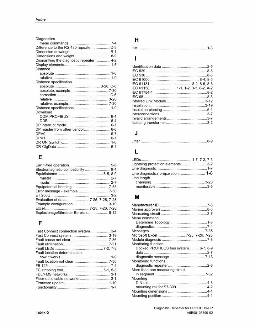
Index
Diagnostic Repeater for PROFIBUS-DPIndex-2 A5E00103899-02
Diagnosticsmenu commands ....................................... 7-4
Difference to the RS 485 repeater .................C-3Dimension drawings.......................................B-1Dimensions and weight.................................. 8-9Dismantling the diagnostic repeater............... 4-2Display elements............................................ 1-5Distance
absolute ..................................................... 1-8relative ....................................................... 1-9
Distance specificationabsolute ........................................... 3-20, C-6absolute, example.................................... 7-30correction ...................................................C-6relative ..................................................... 3-20relative, example...................................... 7-30
Distance specifications .................................. 1-9Download
COM PROFIBUS ....................................... 6-4DDB ........................................................... 6-4
DP interrupt mode.......................................... 6-7DP master from other vendor......................... 6-6DPV0 ............................................................. 6-7DPV1 ............................................................. 6-7DR ON (switch) .............................................. 1-6DR-CfgData ................................................... 6-4
EEarth-free operation ....................................... 5-6Electromagnetic compatibility ........................ 8-4Equidistance ........................................... 6-5, 8-9
master........................................................ 2-7mode.......................................................... 2-7
Equipotential bonding .................................. 7-33Error message - example............................. 7-30ET 200U......................................................... 3-2Evaluation of data ......................7-25, 7-26, 7-28Example configuration ................................. 3-10Excel ..........................................7-25, 7-26, 7-28Explosionsgefährdeter Bereich .................... 8-12
FFast Connect connection system................... 3-4Fast Connect system ................................... 3-19Fault cause not clear.................................... 7-36Fault elimination........................................... 7-31Fault LEDs .............................................. 7-2, 7-3Fault location determination
how it works ............................................... 1-9Fault location not clear................................. 7-36FB 125 ........................................................... 7-4FC stripping tool...................................... 5-1, 5-3FDL/FMS networks ........................................ 3-1Fiber-optic cable networks ............................. 3-1Firmware update.......................................... 1-10Functionality................................................... 1-7
HHMI.................................................................1-3
IIdentification data ...........................................2-5IEC 529 ..........................................................8-8IEC 536 ..........................................................8-8IEC 61000 .............................................. 8-4, 8-5IEC 61131 ....................................... 8-2, 8-6, 8-8IEC 61158 .........................1-1, 1-2, 3-3, 8-2, A-2IEC 61784-1 ...................................................8-2IEC 68 ............................................................8-8Infrared Link Module.....................................3-12Installation ....................................................3-19Insulation piercing ..........................................5-1Interconnections .............................................3-7Invalid arrangements ......................................3-7Isolating transformer.......................................3-2
JJitter ...............................................................8-9
LLEDs................................................ 1-7, 7-2, 7-3Lightning protection elements.........................3-2Line diagnostic ...............................................1-7Line diagnostics preparation......................... 1-8Line length
changing...................................................3-20monitorable.................................................3-5
MManufacturer ID..............................................7-8Marine approvals............................................8-3Measuring circuit ............................................3-7Menu command
Determine Topology ...................................1-8diagnostics .................................................7-4
Messages .....................................................7-35Microsoft Excel .......................... 7-25, 7-26, 7-28Module diagnosis ...........................................7-8Monitoring function
clocked PROFIBUS bus system......... 6-7, 8-9data ............................................................2-7diagnostic message..................................7-13
Monitoring functionsdiagnostic repeater .....................................2-6
More than one measuring circuitin segment................................................7-32
MountingDIN rail .......................................................4-3mounting rail for S7-300 .............................4-2
Mounting dimensions .....................................4-1Mounting position ...........................................4-1
Index
Diagnostic Repeater for PROFIBUS-DPA5E00103899-02 Index-3
Mounting railDIN rail .......................................................4-1S7-300........................................................4-1
MPI interface ..................................................6-8MPI networks .................................................3-1Multiple fault .................................................7-36Multiple-stage diagnostic concept ................3-19
NNetwork design
with component with repeater function .....3-14with OLM ..................................................3-17with RS 485 repeater................................3-15
Nodesadding ......................................................3-20exchanging...............................................3-20removing ..................................................3-20
Non-Siemens DP master................................6-6Note
activating the firmware .............................1-10addressing..................................................6-1cables without the Fast Connect
connection system..................................3-4certificates and approvals...........................8-2components with repeater function...........3-12diagnostic frame.........................................7-5insulation piercing technique .......5-1, A-1, A-2time ............................................................2-4topology determination ...............................6-9Zone 2 ......................................................8-14
OOperating elements ........................................1-5Operator interface systems ............................1-3Optical Bus Terminal ....................................3-12Optical Link Module......................................3-12Order numbers .............................................. A-1
diagnostic repeater and accessories ......... A-1manuals..................................................... A-2PROFIBUS-DP bus connectors ................ A-1SIMATIC NET PROFIBUS cables ............. A-2
Overvoltages ................................................7-33
PParameter assignment ...................................6-6Parameters.....................................................6-6Party line of the S7-300..................................3-6Permissible arrangements..............................3-7PG socket.......................................................5-6Pin assignment of the Cannon connector.......5-6Plant
changing...................................................3-20design.......................................................3-19extending..................................................3-20
Potential difference.......................................7-33Potentials .....................................................8-10Power consumption......................................8-10
Power loss ................................................... 8-10Power Rail Booster ...................................... 3-12Power supply ................................................. 5-2Prerequisites
addressing ................................................. 6-1bus connectors .......................................... 5-3cables ........................................................ 5-3commissioning ........................................... 6-8configuration .............................................. 6-3monitoring function .................................... 2-7parameter assignment ............................... 6-6repeater function........................................ 2-1
PROFIBUS addresschanging .................................................... 6-2
PROFIBUS address....................................... 1-6setting ........................................................ 6-2
PROFIBUS addresseschanging .................................................. 3-20
PROFIBUS cables .........................................A-2Programming device connection
diagnostic repeater .................................... 5-6integrated terminating resistor ................... 5-6
RRange of application of the
diagnostic repeater .................................... 1-4Records ....................................................... 8-11Reflection fault rate...................................... 7-31Relative distance ........................................... 1-9Relative distance specification..................... 3-20Relative distance specification, example ..... 7-30Repeater function .......................................... 1-6
deactivating................................................ 2-2fundamentals ............................................. 2-1
Repeating bus components ..................3-12, C-3Replacement................................................ 3-20Requirements
bus connectors .......................................... 3-3cables ........................................................ 3-4updating the firmware .............................. 1-10
RS 485 repeater .......................................... 3-12Rules for design............................................. 3-1
SScreen short circuit ...................................... 7-34Section monitoring ....................................... 3-13Segment de-activated.................................. 7-35SEGMENT DP3
connecting/disconnecting........................... 5-4example ..................................................... 3-8
SEGMENT DP3 (switch)................................ 1-6Service........................................................... 2-2SFB 52 "RDREC" ........................................ 7-14SFC 103 "DP_TOPOL" .................................. 1-7SFC 59 "RD_REC" ...................................... 7-14Shipping and storage conditions.................... 8-6Short circuit.................................................. 7-34Signal level

Index
Diagnostic Repeater for PROFIBUS-DPIndex-4 A5E00103899-02
no signal level ................................... 2-1, 7-35unstable ................................................... 7-35
Signal level instable ....................................... 2-1Signaling system faults .................................. 7-4SIMATIC NET ................................................ 3-1SIMATIC NET PROFIBUS cables...........3-4, A-2Slide............................................................... 4-2Spur lines....................................................... 3-6Standards ...................................................... 8-1Statistics buffer .............................................. 2-3
example ................................................... 7-29STEP 7..................................................... 7-28user program............................................ 7-20
Status LEDs................................................... 7-2STEP 7
menu command for diagnostics ................. 7-4menu command for topology determination1-8versions ..................................................... 6-3
Strain relief..................................................... 5-3Stripping......................................................... 5-3Stripping tool .................................................. 5-1Stripping Tool............................................... 3-19Supply voltage ............................................... 5-2Switch
BUS ADDRESS ......................................... 1-6DR ON ....................................................... 1-6SEGMENT DP3 ......................................... 1-6TERMINATOR DP1 ................................... 1-6
System problems ........................................... 1-3
TTAG ............................................................... 2-5TDP_Monitoring............................................. 6-7TDX monitoring.............................................. 2-6TDX_Monitoring............................................. 6-7Terminals ....................................................... 5-2TERMINATOR DP1
connecting/disconnecting........................... 5-4example ..................................................... 3-9
TERMINATOR DP1 (switch) .......................... 1-6Test device BT 200 ...................................... 3-19Throughput time............................................. 8-9Time
record format.............................................. 2-4setting ........................................................ 2-3user program.............................................. 2-4
Time stamp .................................................. 7-15
Toolfor mounting ...............................................4-1for wiring.....................................................5-1
Topology determinationlimits ...........................................................6-9
Topology determinationcarrying out.................................................6-8deactivating ................................................6-7Duration......................................................6-9how it works................................................1-8not possible ..............................................7-37preparation .................................................6-8user program ..............................................6-9with COM PROFIBUS ................................6-8with SFC 103..............................................6-9with STEP 7................................................6-8
Topology tableexample....................................................7-25STEP 7 .....................................................7-24user program ............................................7-14
Transfer rate...................................................8-9TSYNC diagnostic module ................... 6-5, 7-13TSYNC diagnostic status..............................7-13
UUngrounded design ........................................5-6User questions
diagnostic messages ................................. C-5difference to the RS 485 repeater ............. C-3topology and fault point determination....... C-1
VValid interconnections ....................................3-7Voltages .......................................................8-10
WWeight ............................................................8-9Wire break ....................................................7-34Wire short circuit...........................................7-34
ZZone 2 ..........................................................8-12

s
Copyright © Siemens AG 2006
Siemens Aktiengesellschaft A5E00352937-03
SIMATIC
Product Information 12/2006
Use of subassemblies/modules in a Zone 2 Hazardous Area
Language Titel Page
Deutsch Einsatz der Baugruppen/Module im explosionsgeschützten Bereich Zone 2 2
English Use of subassemblies/modules in a Zone 2 Hazardous Area 5
Français Utilisation des modules / coupleurs dans la zone à risque d'explosion 2 8
Español Aplicación de los módulos / tarjetas en áreas con peligro de explosión, zona 2 11
Italiano Impiego delle unità/moduli nell'area a pericolo di esplosione zona 2 14
Nederlands Gebruik van de componenten/modulen in het explosief gebied zone 2 17
Dansk Brug af komponenter/moduler i det eksplosionsfarlige område zone 2 20
Suomi Rakenneryhmien/moduulien käyttö räjähdysvaarannetuilla alueilla, vyöhyke 2 23
Svenska Användning av komponentgrupperna/modulerna i explosionsriskområde zon 2 26
Português Uso de grupos construtivos/módulos em área exposta ao perigo de explosão 2 29
Ελληνικά Χρήση των δομικών συγκροτημάτων/μονάδων σε επικίνδυνη για έκρηξη περιοχή, ζώνη 2 32
Česky Použití konstrukčních skupin / modulů v prostředí s nebezpečím výbuchu Zóna 2 35
Estnisch Sõlmede/moodulite kasutamine plahvatusohtliku piirkonna tsoonis 2 38
Latviski Ierīču/moduļu pielietojums sprādzienbīstamas teritorijas zonā 2 41
Lietuviška Konstrukcinių grupių/modulių panaudojimas sprogioje 2 zonos aplinkoje 44
Magyar A főegységek/modulok alkalmazása a 2. zóna robbanásveszélyes környezetben 47
Malti Tqegħid tal-Komponenti / Modules fiż-Żona 2, fejn hemm Riskju ta' Splużjoni 50
Polski Zastosowanie grup konstrukcyjnych / modułów w 2 strefie zagrożenia wybuchem 53
Slovensky Použitie konštrukčných skupín / modulov v prostredí s nebezpečenstvom výbuchu zóny 2 56
Slovensko Uporaba sklopov/modulov v eksplozivno ogroženem območju cone 2 59
Türkçe Patlama tehlikesi olan Alan 2 bölgesinde ünite gruplarının/modüllerin kullanılması 62
Български Използване на електронни блокове/модули във взривоопасната област Зона 2 65
Română Utilizarea unităţilor constructive/modulelor în domeniul cu potenţial exploziv din zona 2 68

Deutsch
2 Product Information on the Use of subassemblies/modules in a Zone 2 Hazardous Area A5E00352937-03
Einsatz der Baugruppen/Module im explosions-gefährdeten Bereich Zone 2
Zugelassene Baugruppen/Module
Nachfolgend finden Sie wichtige Hinweise für die Installation der Baugruppen/Module im explosionsgefährdeten Bereich.
Die Liste mit den zugelassenen Baugruppen/Module finden Sie im Internet:
http://support.automation.siemens.com/WW/view/de/
Geben Sie auf dieser Webseite (im Suchfenster) die dazugehörige Beitrags-ID ein, siehe Tabelle.
Fertigungsort / Zulassung
II 3 G EEx nA II T3 .. T6 nach EN 60079-15 : 2003
Prüfnummer: siehe Tabelle
Fertigungsort Baugruppen/Module Prüfnummer Beitrags-ID
ET 200S ET 200S Fehlersichere Module
KEMA 01 ATEX 1238X
24037700
S7-300 ET 200M Buskopplung DP/PA Diagnoserepeater S7-300 Fehlersichere Baugruppen
KEMA 02 ATEX 1096X
24038475
Siemens AG, Bereich A&D Werner-von-Siemens-Straße 50 92224 Amberg Germany
PROFIBUS-Busanschlussstecker
KEMA 04 ATEX 1151X
24028800
S7-400 KEMA 03 ATEX 1125X
21479867
S7-300 CP TS Adapter II TS Adapter IE
KEMA 03 ATEX 1228X
21497622
SIMATIC NET KEMA 03 ATEX 1226X
21089482
Siemens AG, Bereich A&D Östliche Rheinbrücken-straße 50 76187 Karlsruhe Germany
ET 200M Marshalled Termination Assemblies
KEMA 05 ATEX 1137X
24193554
Hinweis
Baugruppen/Module mit der Zulassung II 3 G EEx nA II T3 .. T6 dürfen nur in SIMATIC-Systemen der Gerätekategorie 3 eingesetzt werden.

Deutsch
Product Information on the Use of subassemblies/modules in a Zone 2 Hazardous Area 3 A5E00352937-03
Instandhaltung
Für eine Reparatur müssen die betroffene Baugruppen/Module an den Fertigungsort geschickt werden. Nur dort darf die Reparatur durchgeführt werden.
Besondere Bedingungen für:
KEMA 01 ATEX 1238X
KEMA 02 ATEX 1096X
KEMA 03 ATEX 1125X, ATEX 1226X, ATEX 1228X
1. Baugruppen/Module müssen in ein geeignetes Gehäuse eingebaut werden. Dieses Gehäuse muss mindestens die Schutzart IP 54 (nach EN 60529) gewährleisten. Dabei sind die Umgebungsbedingungen zu berücksichtigen, in denen das Gerät installiert wird. Für das Gehäuse muss eine Herstellererklärung für Zone 2 vorliegen (gemäß EN 60079-15).
2. Wenn am Kabel bzw. an der Kabeleinführung dieses Gehäuses unter Betriebs-bedingungen eine Temperatur > 70 °C erreicht wird oder wenn unter Betriebs-bedingungen die Temperatur an der Aderverzweigung > 80 °C sein kann, müssen die Temperatureigenschaften der Kabel mit den tatsächlich gemessenen Temperaturen übereinstimmen.
3. Die eingesetzten Kabeleinführungen müssen der geforderten IP-Schutzart und dem Abschnitt 6.2 (gemäß EN 60079-15) entsprechen.
4. Es müssen Maßnahmen getroffen werden, dass die Nennspannung durch Transienten um nicht mehr als 40 % überschritten werden kann.
Besondere Bedingungen für KEMA 04 ATEX 1151X
1. Die PROFIBUS-Busanschlussstecker müssen so installiert werden, dass sie vor mechanischer Gefahr geschützt sind.
2. Wenn das Eindringen von Feuchtigkeit und Staub nicht auszuschließen ist, sind die PROFIBUS-Busanschlussstecker Serie 6ES7972-... in ein geeignetes Gehäuse einzubauen. Dieses Gehäuse muss mindestens die Schutzart IP 54 (nach EN 60529) gewährleisten.
3. Die PROFIBUS-Busanschlussstecker müssen mit den mitgelieferten Schrauben vorschriftsgemäß befestigt werden.
4. Das Anschließen bzw. Trennen von spannungsführenden Leitern oder der Betätigung Geräteschalter, z.B Installations- oder Wartungszwecken, ist nur erlaubt wenn sichergestellt ist, dass der Bereich nicht explosionsgefährdet ist.

Deutsch
4 Product Information on the Use of subassemblies/modules in a Zone 2 Hazardous Area A5E00352937-03
Besondere Bedingungen für KEMA 05 ATEX 1137X
1. Baugruppen/Module müssen in ein geeignetes Gehäuse eingebaut werden. Dieses Gehäuse muss mindestens die Schutzart IP 54 (nach EN 60529) gewährleisten. Dabei sind die Umgebungsbedingungen zu berücksichtigen, in denen das Gerät installiert wird. Für das Gehäuse muss eine Herstellererklärung für Zone 2 vorliegen (gemäß EN 60079-15).
2. Wenn am Kabel bzw. an der Kabeleinführung dieses Gehäuses unter Betriebs-bedingungen eine Temperatur > 70 °C erreicht wird oder wenn unter Betriebs-bedingungen die Temperatur an der Aderverzweigung > 80 °C sein kann, müssen die Temperatureigenschaften der Kabel mit den tatsächlich gemessenen Temperaturen übereinstimmen.
3. Es müssen Maßnahmen getroffen werden, dass die Nennspannung durch Transienten um nicht mehr als 40 % überschritten werden kann.
Weitere Informationen
Weitere Informationen zu den Baugruppen/Modulen finden Sie im dazugehörigen Handbuch.

English
Product Information on the Use of subassemblies/modules in a Zone 2 Hazardous Area A5E00352937-03
5
Use of subassemblies/modules in a Zone 2 Hazardous Area
Approved devices/modules
Below you will find important information on the installation of the subassemblies/modules in a hazardous area.
You can find the list of approved devices/modules on the Internet:
http://support.automation.siemens.com/WW/view/en/
Enter the associated article ID in the search window on this website, see table.
Production Location / Certification
II 3 G EEx nA II T3 .. T6 to EN 60079-15 : 2003
Test number: see table below
Production Location Subassemblies/Modules Test Number Article ID
ET-200S ET 200S fault-tolerant modules
KEMA 01 ATEX 1238X
24037700
S7-300 ET-200M DP/PA bus interface Diagnostics repeater S7-300 fault-tolerant modules
KEMA 02 ATEX 1096X
24038475
Siemens AG, Bereich A&D Werner-von-Siemens-Straße 50 92224 Amberg Germany
PROFIBUS Bus Connector Plug
KEMA 04 ATEX 1151X
24028800
S7-400 KEMA 03 ATEX 1125X
21479867
S7-300 CP TS Adapter II TS Adapter IE
KEMA 03 ATEX 1228X
21497622
Siemens AG, Bereich A&D Östliche Rheinbrücken-straße 50 76187 Karlsruhe Germany
SIMATIC NET KEMA 03 ATEX 1226X
21089482
ET 200M Marshalled Termination Assemblies
KEMA 05 ATEX 1137X
24193554
Note
Subassemblies/modules with II 3 G EEx nA II T3 .. T6 certification can only be used in SIMATIC systems rated as category 3 equipment.

English
Product Information on the Use of subassemblies/modules in a Zone 2 Hazardous Area A5E00352937-03 6
Maintenance
If repair is necessary, the affected subassemblies/modules must be sent to the production location. Repairs can only be carried out there.
Special conditions for:
KEMA 01 ATEX 1238X
KEMA 02 ATEX 1096X
KEMA 03 ATEX 1125X, ATEX 1226X, ATEX 1228X
1. Subassemblies/modules must be installed in an adequate housing. This must comply with the IP 54 degree of protection (according to EN 60529) as a minimum. The environmental conditions under which the equipment is installed must be taken into account. There must be a manufacturer's declaration for zone 2 available for the housing (in accordance with EN 60079-15).
2. If a temperature of > 70 °C is reached in the cable or at the cable entry of this housing under operating conditions, or if a temperature of > 80 °C can be reached at the junction of the conductors under operating conditions, the temperature-related properties of the cables must correspond to the temperatures actually measured.
3. The cable entries used must comply with the required IP degree of protection and Section 6.2 (in accordance with EN 60079-15).
4. Steps must be taken to ensure that the rated voltage through transients cannot be exceeded by more than 40 %.
Special Conditions for KEMA 04 ATEX 1151X
1. The PROFIBUS bus connector plugs must be installed so that they are protected from mechanical hazards.
2. If the ingress of moisture and dust cannot be ruled out, the PROFIBUS bus connection plugs series 6ES7972 ... are to be installed in a suitable housing. This housing must guarantee at least the protection type IP 54 (according to EN 60529).
3. The PROFIBUS bus connection plugs must be attached according to instructions using the supplied screws.
4. The connecting or disconnecting of live conductors or operation of device switches, e.g. for installation or servicing purposes is only allowed when it has been ensured that the area is not explosive.

English
Product Information on the Use of subassemblies/modules in a Zone 2 Hazardous Area A5E00352937-03
7
Special Conditions for KEMA 05 ATEX 1137X
1. Subassemblies/modules must be installed in an adequate housing. This must comply with the IP 54 degree of protection (according to EN 60529) as a minimum. The environmental conditions under which the equipment is installed must be taken into account. There must be a manufacturer's declaration for zone 2 available for the housing (in accordance with EN 60079-15).
2. If a temperature of > 70 °C is reached in the cable or at the cable entry of this housing under operating conditions, or if a temperature of > 80 °C can be reached at the junction of the conductors under operating conditions, the temperature-related properties of the cables must correspond to the temperatures actually measured.
3. Steps must be taken to ensure that the rated voltage through transients cannot be exceeded by more than 40 %.
Further Information
You can find further information on devices/modules in the associated handbook.

Français
8 Product Information on the Use of subassemblies/modules in a Zone 2 Hazardous Area A5E00352937-03
Utilisation des modules / coupleurs dans la zone à risque d'explosion 2
Les modules de construction agréés
Vous trouverez ci-après des informations importantes pour l'installation de la station de périphérie décentralisée des modules / coupleurs dans la zone à risque d'explosion. Vous trouverez une liste de modules de construction agréés sur internet http://support.automation.siemens.com/WW/view/fr/
Entrez sur le site internet (dans la fenêtre de recherche), le numéro d’identification correspondant de l’article, voir tableau.
Lieu de fabrication / Homologation
II 3 G EEx nA II T3 .. T6 selon EN 60079-15 : 2003
Numéro de contrôle : voir tableau
Lieu de fabrication Modules de construction Numéro de contrôle
Numéro d’ident. de
l’article ET 200S ET 200S Fehlersichere Module
KEMA 01 ATEX 1238X
24037700
S7-300 ET 200M Buskopplung DP/PA Diagnoserepeater S7-300 Modules de sécurité anti-erreurs
KEMA 02 ATEX 1096X
24038475
Siemens AG, Bereich A&D Werner-von-Siemens-Straße 50 92224 Amberg Germany
PROFIBUS-connecteur de bus
KEMA 04 ATEX 1151X
24028800
S7-400 KEMA 03 ATEX 1125X
21479867
S7-300 CP TS Adapter II TS Adapter IE
KEMA 03 ATEX 1228X
21497622
SIMATIC NET KEMA 03 ATEX 1226X
21089482
Siemens AG, Bereich A&D Östliche Rheinbrücken-straße 50 76187 Karlsruhe Germany
ET 200M Marshalled Termination Assemblies
KEMA 05 ATEX 1137X
24193554
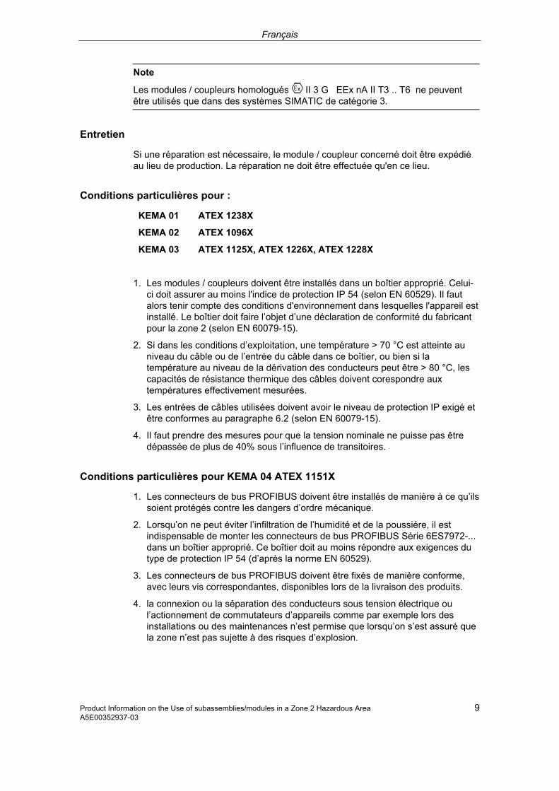
Français
Product Information on the Use of subassemblies/modules in a Zone 2 Hazardous Area 9 A5E00352937-03
Note
Les modules / coupleurs homologués II 3 G EEx nA II T3 .. T6 ne peuvent être utilisés que dans des systèmes SIMATIC de catégorie 3.
Entretien
Si une réparation est nécessaire, le module / coupleur concerné doit être expédié au lieu de production. La réparation ne doit être effectuée qu'en ce lieu.
Conditions particulières pour :
KEMA 01 ATEX 1238X
KEMA 02 ATEX 1096X
KEMA 03 ATEX 1125X, ATEX 1226X, ATEX 1228X
1. Les modules / coupleurs doivent être installés dans un boîtier approprié. Celui-ci doit assurer au moins l'indice de protection IP 54 (selon EN 60529). Il faut alors tenir compte des conditions d'environnement dans lesquelles l'appareil est installé. Le boîtier doit faire l’objet d’une déclaration de conformité du fabricant pour la zone 2 (selon EN 60079-15).
2. Si dans les conditions d’exploitation, une température > 70 °C est atteinte au niveau du câble ou de l’entrée du câble dans ce boîtier, ou bien si la température au niveau de la dérivation des conducteurs peut être > 80 °C, les capacités de résistance thermique des câbles doivent corespondre aux températures effectivement mesurées.
3. Les entrées de câbles utilisées doivent avoir le niveau de protection IP exigé et être conformes au paragraphe 6.2 (selon EN 60079-15).
4. Il faut prendre des mesures pour que la tension nominale ne puisse pas être dépassée de plus de 40% sous l’influence de transitoires.
Conditions particulières pour KEMA 04 ATEX 1151X
1. Les connecteurs de bus PROFIBUS doivent être installés de manière à ce qu’ils soient protégés contre les dangers d’ordre mécanique.
2. Lorsqu’on ne peut éviter l’infiltration de l’humidité et de la poussière, il est indispensable de monter les connecteurs de bus PROFIBUS Série 6ES7972-... dans un boîtier approprié. Ce boîtier doit au moins répondre aux exigences du type de protection IP 54 (d’après la norme EN 60529).
3. Les connecteurs de bus PROFIBUS doivent être fixés de manière conforme, avec leurs vis correspondantes, disponibles lors de la livraison des produits.
4. la connexion ou la séparation des conducteurs sous tension électrique ou l’actionnement de commutateurs d’appareils comme par exemple lors des installations ou des maintenances n’est permise que lorsqu’on s’est assuré que la zone n’est pas sujette à des risques d’explosion.
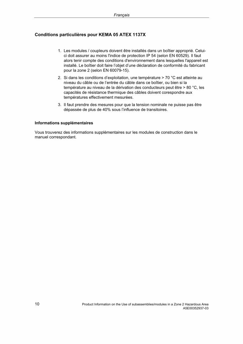
Français
10 Product Information on the Use of subassemblies/modules in a Zone 2 Hazardous Area A5E00352937-03
Conditions particulières pour KEMA 05 ATEX 1137X
1. Les modules / coupleurs doivent être installés dans un boîtier approprié. Celui-ci doit assurer au moins l'indice de protection IP 54 (selon EN 60529). Il faut alors tenir compte des conditions d'environnement dans lesquelles l'appareil est installé. Le boîtier doit faire l’objet d’une déclaration de conformité du fabricant pour la zone 2 (selon EN 60079-15).
2. Si dans les conditions d’exploitation, une température > 70 °C est atteinte au niveau du câble ou de l’entrée du câble dans ce boîtier, ou bien si la température au niveau de la dérivation des conducteurs peut être > 80 °C, les capacités de résistance thermique des câbles doivent corespondre aux températures effectivement mesurées.
3. Il faut prendre des mesures pour que la tension nominale ne puisse pas être dépassée de plus de 40% sous l’influence de transitoires.
Informations supplémentaires Vous trouverez des informations supplémentaires sur les modules de construction dans le manuel correspondant.

Español
Product Information on the Use of subassemblies/modules in a Zone 2 Hazardous Area A5E00352937-03
11
Aplicación de los módulos / tarjetas en áreas con peligro de explosión, zona 2
Grupos / Módulos permitidos
A continuación encontrará importantes informaciones para la instalación de los módulos / tarjetas en áreas con peligro de explosión.
Podrá encontrar la lista con los grupos y módulos en Internet:
http://support.automation.siemens.com/WW/view/es/
Indique en esta página Web (en la ventana de búsqueda) el ID del artículo correspondiente, véase tabla.
Lugar de fabricación / Homologación
II 3 G EEx nA II T3 .. T6 según la norma EN 60079-15 : 2003
Número de comprobación: véase tabla
Lugar de fabricación Módulos / tarjetas Número de comprobación
ID del artículo
ET 200S Grupos ET 200S a prueba de fallos
KEMA 01 ATEX 1238X
24037700
S7-300 ET 200M Acoplamiento de bus DP/PA Repetidor de diagnóstico Grupos S7-300 a prueba de fallos
KEMA 02 ATEX 1096X
24038475
Siemens AG, Bereich A&D Werner-von-Siemens-Straße 50 92224 Amberg Germany
Clavija de conexión de PROFIBUS
KEMA 04 ATEX 1151X
24028800
S7-400 KEMA 03 ATEX 1125X
21479867
S7-300 CP TS Adapter II Adaptador TS IE
KEMA 03 ATEX 1228X
21497622
SIMATIC NET KEMA 03 ATEX 1226X
21089482
Siemens AG, Bereich A&D Östliche Rheinbrücken- straße 50 76187 Karlsruhe Germany
ET 200M Marshalled Termination Assemblies
KEMA 05 ATEX 1137X
24193554
Nota
Los grupos y módulos con la autorización II 3 G EEx nA II T3 . T6 sólo podrán emplearse en sistemas SIMATIC de la categoría de equipos 3.
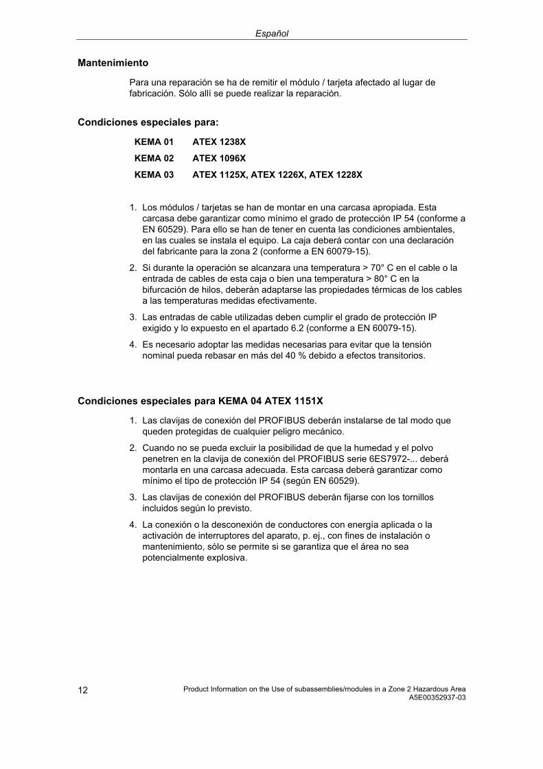
Español
Product Information on the Use of subassemblies/modules in a Zone 2 Hazardous Area A5E00352937-03 12
Mantenimiento
Para una reparación se ha de remitir el módulo / tarjeta afectado al lugar de fabricación. Sólo allí se puede realizar la reparación.
Condiciones especiales para:
KEMA 01 ATEX 1238X
KEMA 02 ATEX 1096X
KEMA 03 ATEX 1125X, ATEX 1226X, ATEX 1228X
1. Los módulos / tarjetas se han de montar en una carcasa apropiada. Esta carcasa debe garantizar como mínimo el grado de protección IP 54 (conforme a EN 60529). Para ello se han de tener en cuenta las condiciones ambientales, en las cuales se instala el equipo. La caja deberá contar con una declaración del fabricante para la zona 2 (conforme a EN 60079-15).
2. Si durante la operación se alcanzara una temperatura > 70° C en el cable o la entrada de cables de esta caja o bien una temperatura > 80° C en la bifurcación de hilos, deberán adaptarse las propiedades térmicas de los cables a las temperaturas medidas efectivamente.
3. Las entradas de cable utilizadas deben cumplir el grado de protección IP exigido y lo expuesto en el apartado 6.2 (conforme a EN 60079-15).
4. Es necesario adoptar las medidas necesarias para evitar que la tensión nominal pueda rebasar en más del 40 % debido a efectos transitorios.
Condiciones especiales para KEMA 04 ATEX 1151X
1. Las clavijas de conexión del PROFIBUS deberán instalarse de tal modo que queden protegidas de cualquier peligro mecánico.
2. Cuando no se pueda excluir la posibilidad de que la humedad y el polvo penetren en la clavija de conexión del PROFIBUS serie 6ES7972-... deberá montarla en una carcasa adecuada. Esta carcasa deberá garantizar como mínimo el tipo de protección IP 54 (según EN 60529).
3. Las clavijas de conexión del PROFIBUS deberán fijarse con los tornillos incluidos según lo previsto.
4. La conexión o la desconexión de conductores con energía aplicada o la activación de interruptores del aparato, p. ej., con fines de instalación o mantenimiento, sólo se permite si se garantiza que el área no sea potencialmente explosiva.
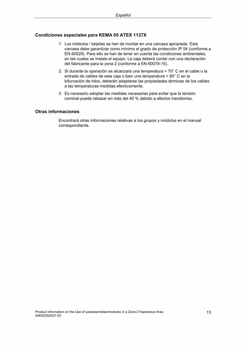
Español
Product Information on the Use of subassemblies/modules in a Zone 2 Hazardous Area A5E00352937-03
13
Condiciones especiales para KEMA 05 ATEX 1137X
1. Los módulos / tarjetas se han de montar en una carcasa apropiada. Esta carcasa debe garantizar como mínimo el grado de protección IP 54 (conforme a EN 60529). Para ello se han de tener en cuenta las condiciones ambientales, en las cuales se instala el equipo. La caja deberá contar con una declaración del fabricante para la zona 2 (conforme a EN 60079-15).
2. Si durante la operación se alcanzara una temperatura > 70° C en el cable o la entrada de cables de esta caja o bien una temperatura > 80° C en la bifurcación de hilos, deberán adaptarse las propiedades térmicas de los cables a las temperaturas medidas efectivamente.
3. Es necesario adoptar las medidas necesarias para evitar que la tensión nominal pueda rebasar en más del 40 % debido a efectos transitorios.
Otras informaciones
Encontrará otras informaciones relativas a los grupos y módulos en el manual correspondiente.

Italiano
Product Information on the Use of subassemblies/modules in a Zone 2 Hazardous Area A5E00352937-03 14
Impiego di unità/moduli nell'area a pericolo di esplosione zona 2
Unità/moduli omologati
Qui di seguito sono riportate delle avvertenze importanti per l'installazione delle unità/moduli nell'area a pericolo di esplosione.
L'elenco di unità/moduli omologati è reperibile in Internet:
http://support/automation.siemens.com/WW/view/it/
In questa pagina web (nella maschera di ricerca), inserire il relativo codice articolo, vedi tabella.
Luogo di produzione / Omologazione
II 3 G EEx nA II T3 .. T6 secondo EN 60079-15 : 2003
Numero di controllo: vedi tabella
Luogo di produzione Unità/moduli Numero di controllo
Codice articolo
ET 200S Unità ad elevata sicurezza ET 200S
KEMA 01 ATEX 1238X
24037700
S7-300 ET 200M Accoppiamento di bus DP/PA Repeater di diagnosticaUnità ad elevata sicurezza S7-300
KEMA 02 ATEX 1096X
24038475
Siemens AG, Bereich A&D Werner-von-Siemens- Straße 50 92224 Amberg Germany
Connettore bus PROFIBUS
KEMA 04 ATEX 1151X
24028800
S7-400 KEMA 03 ATEX 1125X
21479867
S7-300 CP TS Adapter II TS Adapter IE
KEMA 03 ATEX 1228X
21497622
SIMATIC NET KEMA 03 ATEX 1226X
21089482
Siemens AG, Bereich A&D Östliche Rheinbrücken- straße 50 76187 Karlsruhe Germany
ET 200M Marshalled Termination Assemblies
KEMA 05 ATEX 1137X
24193554

Italiano
Product Information on the Use of subassemblies/modules in a Zone 2 Hazardous Area A5E00352937-03
15
Avvertenza
Le unità/moduli con l'omologazione II 3 G EEx nA II T3 .. T6 possono essere impiegati solo nei sistemi SIMATIC della categoria di apparecchiature 3.
Manutenzione
Per una riparazione, le unità/i moduli interessati devono essere inviati al luogo di produzione. La riparazione può essere effettuata solo lì.
Condizioni particolari per:
KEMA 01 ATEX 1238X
KEMA 02 ATEX 1096X
KEMA 03 ATEX 1125X, ATEX 1226X, ATEX 1228X
1. Le unità/i moduli devono essere montati in un contenitore adatto. Questo contenitore deve assicurare almeno il tipo di protezione IP 54. In questo caso bisogna tenere conto delle condizioni ambientali nelle quali l'apparecchiatura viene installata. Per il contenitore deve essere presente una dichiarazione del costruttore per la zona 2 (secondo EN 60079-15).
2. Se nei cavi o nel loro punto di ingresso in questo contenitore viene raggiunta in condizioni di esercizio una temperatura > 70 °C o se in condizioni di esercizio la temperatura nella derivazione dei fili può essere > 80 °C, le caratteristiche di temperatura dei cavi devono essere conformi alla temperatura effettivamente misurata.
3. Gli ingressi dei cavi usati devono essere conformi al tipo di protezione richiesto e alla sezione 6.2 (secondo EN 60079-15).
4. Devono essere prese delle misure per evitare che la tensione nominale possa essere superata per più del 40% da parte di transienti.
Condizioni particolari per KEMA 04 ATEX 1151X
1. I connettori bus PROFIBUS devono essere installati in modo tale da non essere esposti a pericolo meccanico.
2. Se è impossibile escludere la penetrazione di umidità e polvere, i connettori bus PROFIBUS della serie 6ES7972-… devono essere installati in un contenitore adatto. Questo contenitore deve essere conforme almeno al tipo di protezione IP 54 (secondo EN 60529).
3. I connettori bus PROFIBUS devono essere assicurati mediante le viti allegate e secondo le disposizioni.
4. La connessione o l’interruzione di conduttori in tensione oppure l’azionamento di interruttori, per es. per eseguire l’installazione o la manutenzione, sono consentiti solo previa verifica dell'assenza del pericolo di esplosione nell’area.

Italiano
Product Information on the Use of subassemblies/modules in a Zone 2 Hazardous Area A5E00352937-03 16
Condizioni particolari per KEMA 05 ATEX 1137X 1. Le unità/i moduli devono essere montati in un contenitore adatto. Questo
contenitore deve assicurare almeno il tipo di protezione IP 54 (secondo EN 60529). In questo caso bisogna tenere conto delle condizioni ambientali nelle quali l'apparecchiatura viene installata. Per il contenitore deve essere presente una dichiarazione del costruttore per la zona 2 (secondo EN 60079-15).
2. Se nei cavi o nel loro punto di ingresso in questo contenitore viene raggiunta in condizioni di esercizio una temperatura > 70 °C o se in condizioni di esercizio la temperatura nella derivazione dei fili può essere > 80 °C, le caratteristiche di temperatura dei cavi devono essere conformi alla temperatura effettivamente misurata.
3. Devono essere prese delle misure per evitare che la tensione nominale possa essere superata per più del 40% da parte di transienti.
Ulteriori informazioni
Ulteriori informazioni relative a unità/moduli sono reperibili nel relativo manuale.

Nederlands
Product Information on the Use of subassemblies/modules in a Zone 2 Hazardous Area A5E00352937-03
17
Gebruik van de componenten/modulen in het explosief gebied zone 2
Toegelaten componenten/modulen
Hierna vindt u belangrijke aanwijzingen voor de installatie van de componenten/modulen in het explosief gebied.
De lijst met de toegelaten componenten/modulens vindt u in het internet:
http://support.automation.siemens.com/WW/view/en/
Voer op deze website (in het zoekvenster) de bijhorende bijdrage-ID in, zie tabel.
Productieplaats / Vergunning
II 3 G EEx nA II T3 .. T6 conform EN 60079-15 : 2003
Keuringsnummer: zie tabel
Productieplaats Componenten/modulen Keuringsnummer Bijdrage-ID
ET 200S ET 200S tegen fouten beveiligde componenten
KEMA 01 ATEX 1238X
24037700 Siemens AG, Bereich A&D Werner-von-Siemens-Straße 50 92224 Amberg Germany
S7-300 ET 200 M Buskoppeling DP/PA Diagnoserepeater S7-300 tegen fouten beveiligde componenten
KEMA 02 ATEX 1096X
24038475
PROFIBUS- busaansluitstekker
KEMA 04 ATEX 1151X
24028800
S7-400 KEMA 03 ATEX 1125X
21479867
S7-300 CP TS Adapter II TS Adapter IE
KEMA 03 ATEX 1228X
21497622
Siemens AG, Bereich A&D Östliche Rheinbrücken-straße 50 76187 Karlsruhe Germany
SIMATIC NET KEMA 03 ATEX 1226X
21089482
ET 200M Marshalled Termination Assemblies
KEMA 05 ATEX 1137X
24193554
Opmerking
Componenten/modulen met de vergunning II 3 G EEx nA II T3 .. T6 mogen slechts worden gebruikt in SIMATIC-systemen van de apparaatcategorie 3.

Nederlands
Product Information on the Use of subassemblies/modules in a Zone 2 Hazardous Area A5E00352937-03 18
Instandhouding
Voor een reparatie moeten de betreffende componenten/modulen naar de plaats van vervaardiging worden gestuurd. Alleen daar mag de reparatie worden uitgevoerd.
Speciale voorwaarden voor:
KEMA 01 ATEX 1238X
KEMA 02 ATEX 1096X
KEMA 03 ATEX 1125X, ATEX 1226X, ATEX 1228X
1. Componenten/modulen moeten worden ingebouwd in een geschikte behuizing. Deze behuizing moet minstens de veiligheidsgraad IP 54 waarborgen. Hierbij dient rekening te worden gehouden met de omgevingsvoorwaarden waarin het apparaat wordt geïnstalleerd. Voor de behuizing dient een verklaring van de fabrikant voor zone 2 te worden ingediend (volgens EN 60079-15).
2. Als aan de kabel of aan de kabelinvoering van deze behuizing onder bedrijfsomstandigheden een temperatuur wordt bereikt > 70 °C of als onder bedrijfsomstandigheden de temperatuur aan de adervertakking > 80 °C kan zijn, moeten de temperatuureigenschappen van de kabel overeenstemmen met de werkelijk gemeten temperaturen.
3. De aangebrachte kabelinvoeringen moeten de vereiste IP-veiligheidsgraad hebben en in overeenstemming zijn met alinea 6.2 (volgens EN 60079-15).
4. Er dienen maatregelen te worden getroffen, zodat de nominale spanning door transiënten met niet meer dan 40 % kan worden overschreden.
Bijzondere voorwaarden voor KEMA 04 ATEX 1151X
1. De PROFIBUS-aansluitstekkers moeten dusdanig worden geïnstalleerd, dat zij tegen mechanisch gevaar beschermd zijn.
2. Als het binnendringen van vocht en stof niet kan worden uitgesloten, dienen de PROFIBUS-busaansluitstekkers van de serie 6ES7972-... in een geschikte behuizing te worden gemonteerd. Deze behuizing moet minstens de veiligheidsgraad IP 54 (volgens EN 60529) waarborgen.
3. De PROFIBUS-busaansluitstekkers moeten met de meegeleverde schroeven zoals voorgeschreven worden bevestigd.
4. Het aansluiten of scheiden van spanningvoerende geleiders of het activeren van apparaatschakelaars, bijv.voor installatie- of onderhoudsdoeleinden, is slechts toegestaan als kan worden gewaarborgd dat het gebied niet explosief is.

Nederlands
Product Information on the Use of subassemblies/modules in a Zone 2 Hazardous Area A5E00352937-03
19
Bijzondere voorwaarden voor KEMA 05 ATEX 1137X
1. Componenten/modulen moeten worden ingebouwd in een geschikte behuizing. Deze behuizing moet minstens de veiligheidsgraad IP 54 waarborgen. Hierbij dient rekening te worden gehouden met de omgevingsvoorwaarden waarin het apparaat wordt geïnstalleerd. Voor de behuizing dient een verklaring van de fabrikant voor zone 2 te worden ingediend (volgens EN 60079-15).
2. Als aan de kabel of aan de kabelinvoering van deze behuizing onder bedrijfsomstandigheden een temperatuur wordt bereikt > 70 °C of als onder bedrijfsomstandigheden de temperatuur aan de adervertakking > 80 °C kan zijn, moeten de temperatuureigenschappen van de kabel overeenstemmen met de werkelijk gemeten temperaturen.
3. Er dienen maatregelen te worden getroffen, zodat de nominale spanning door transiënten met niet meer dan 40 % kan worden overschreden.
Verdere informatie
Verdere informatie over de componenten/modulen vindt u in het bijhorende handboek.

Dansk
20 Product Information on the Use of subassemblies/modules in a Zone 2 Hazardous Area A5E00352937-03
Brug af komponenter/moduler i det eksplosionsfarlige område zone 2
Tilladte komponenter/moduler
I det følgende findes vigtige henvisninger vedr. installation af komponenter/moduler i det eksplosionsfarlige område.
En liste med de tilladte komponenter/moduler findes på internettet:
http://support.automation.siemens.com/WW/view/en/
Indtast på denne webside (i søgevinduet) det pågældende bidrags-ID, se tabel.
Produktionssted / Godkendelse
II 3 G EEx nA II T3 .. T6 efter EN 60079-15 : 2003
Kontrolnummer: se tabel
Produktionssted Komponenter/moduler Kontrolnummer Bidrags-ID
ET 200S ET 200S fejlsikre komponenter
KEMA 01 ATEX 1238X
24037700
S7-300 ET 200M Buskobling DP/PA Diagnoserepeater S7-300 fejlsikre komponenter
KEMA 02 ATEX 1096X
24038475
Siemens AG, Bereich A&D Werner-von-Siemens-Straße 50 92224 Amberg Germany
PROFIBUS-busadapterstik
KEMA 04 ATEX 1151X
24028800
S7-400 KEMA 03 ATEX 1125X
21479867
S7-300 CP TS Adapter II TS Adapter IE
KEMA 03 ATEX 1228X
21497622
SIMATIC NET KEMA 03 ATEX 1226X
21089482
Siemens AG, Bereich A&D Östliche Rheinbrücken- straße 50 76187 Karlsruhe Germany
ET 200M Marshalled Termination Assemblies
KEMA 05 ATEX 1137X
24193554
Bemærk
Komponenter/moduler med godkendelsen II 3 G EEx nA II T3 .. T6 må kun monteres i SIMATIC-systemer for udstyrskategori 3.
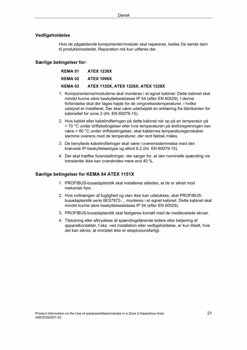
Dansk
Product Information on the Use of subassemblies/modules in a Zone 2 Hazardous Area 21 A5E00352937-03
Vedligeholdelse
Hvis de pågældende komponenter/moduler skal repareres, bedes De sende dem til produktionsstedet. Reparation må kun udføres der.
Særlige betingelser for:
KEMA 01 ATEX 1238X
KEMA 02 ATEX 1096X
KEMA 03 ATEX 1125X, ATEX 1226X, ATEX 1228X
1. Komponenterne/modulerne skal monteres i et egnet kabinet. Dette kabinet skal mindst kunne sikre beskyttelsesklasse IP 54 (efter EN 60529). I denne forbindelse skal der tages højde for de omgivelsestemperaturer, i hvilke udstyret er installeret. Der skal være udarbejdet en erklæring fra fabrikanten for kabinettet for zone 2 (iht. EN 60079-15).
2. Hvis kablet eller kabelindføringen på dette kabinet når op på en temperatur på > 70 °C under driftsbetingelser eller hvis temperaturen på åreforegreningen kan være > 80 °C under driftsbetingelser, skal kablernes temperaturegenskaber stemme overens med de temperaturer, der rent faktisk måles.
3. De benyttede kabelindføringer skal være i overensstemmelse med den krævede IP-beskyttelsestype og afsnit 6.2 (iht. EN 60079-15).
4. Der skal træffes foranstaltninger, der sørger for, at den nominelle spænding via transienter ikke kan overskrides mere end 40 %.
Særlige betingelser for KEMA 04 ATEX 1151X
1. PROFIBUS-busadapterstik skal installeres således, at de er sikret mod mekanisk fare.
2. Hvis indtrængen af fugtighed og støv ikke kan udelukkes, skal PROFIBUS-busadapterstik serie 6ES7972-... monteres i et egnet kabinet. Dette kabinet skal mindst kunne sikre beskyttelsesklasse IP 54 (efter EN 60529).
3. PROFIBUS-busadapterstik skal fastgøres korrekt med de medleverede skruer.
4. Tilslutning eller afbrydelse af spændingsførende ledere eller betjening af apparatkontakter, f.eks. ved installation eller vedligeholdelse, er kun tilladt, hvis det kan sikres, at området ikke er eksplosionsfarligt.

Dansk
22 Product Information on the Use of subassemblies/modules in a Zone 2 Hazardous Area A5E00352937-03
Besondere Bedingungen für KEMA 05 ATEX 1137X
1. Komponenterne/modulerne skal monteres i et egnet kabinet. Dette kabinet skal mindst kunne sikre beskyttelsesklasse IP 54 (efter EN 60529). I denne forbindelse skal der tages højde for de omgivelsestemperaturer, i hvilke udstyret er installeret. Der skal være udarbejdet en erklæring fra fabrikanten for kabinettet for zone 2 (iht. EN 60079-15).
2. Hvis kablet eller kabelindføringen på dette kabinet når op på en temperatur på > 70 °C under driftsbetingelser eller hvis temperaturen på åreforegreningen kan være > 80 °C under driftsbetingelser, skal kablernes temperaturegenskaber stemme overens med de temperaturer, der rent faktisk måles.
3. Der skal træffes foranstaltninger, der sørger for, at den nominelle spænding via transienter ikke kan overskrides mere end 40 %.
Yderligere informationer
Yderligere informationer om komponenterne/modulerne findes i den pågældende manual.

Suomi
Product Information on the Use of subassemblies/modules in a Zone 2 Hazardous Area 23 A5E00352937-03
Rakenneryhmien/moduulien käyttö räjähdysvaarannetuilla alueilla, vyöhyke 2 Sallitut rakenneryhmät/moduulit
Seuraavasta löydätte tärkeitä ohjeita rakenneryhmien/moduulien asennukseen räjähdysvaarannetuilla alueilla. Uusi: Luettelo sallituista rakenneryhmistä/moduuleista on Internetissä:
http://support.automation.siemens.com/WW/view/en/
Syötä tällä Internet-sivulla (hakuikkunassa) kyseinen käyttäjätunnus (ks. taulukko).
Valmistuspaikka / Hyväksyntä
II 3 G EEx nA II T3 - T6 EN 60079-15 : 2003 -standardin mukaan
Tarkastusnumero: katso taulukko
Valmistuspaikka Rakenneryhmät/ moduulit
Tarkastusnumero
Käyttäjä-tunnus
ET 200S ET 200S läpi-iskuvarmat rakenneryhmät
KEMA 01 ATEX 1238X
24037700
S7-300 ET 200M Väyläkytkin DP/PA Dignoositoistin S7-300 läpi-iskuvarmat rakenneryhmät
KEMA 02 ATEX 1096X
24038475
Siemens AG, Bereich A&D Werner-von-Siemens-Straße 5092224 Amberg Germany
PROFIBUS-väyläliitäntäpistoke
24028800
S7-400 KEMA 03 ATEX 1125X
21479867
S7-300 CP TS Adapter II TS Adapter IE
KEMA 03 ATEX 1228X
21497622
SIMATIC NET KEMA 03 ATEX 1226X
21089482
Siemens AG, Bereich A&D Östliche Rheinbrücken- straße 50 76187 Karlsruhe Germany
ET 200M Marshalled Termination Assemblies
24193554
Ohje
Rakenneryhmiä/moduuleja hyväksynnän II 3 G EEx nA II T3 - T6 kanssa saa käyttää ainoastaan laitekategorian 3 SIMATIC-järjestelmissä.

Suomi
24 Product Information on the Use of subassemblies/modules in a Zone 2 Hazardous Area A5E00352937-03
Kunnossapito
Korjausta varten täytyy kyseinen rakenneryhmä/moduuli lähettää valmistuspaikkaan. Korjaus voidaan suorittaa ainoastaan siellä.
Erityiset vaatimukset:
KEMA 01 ATEX 1238X
KEMA 02 ATEX 1096X
KEMA 03 ATEX 1125X, ATEX 1226X, ATEX 1228X
1. Rakenneryhmät/moduulit täytyy asentaa sopivaan koteloon. Tämän kotelon täytyy olla vähintään kotelointiluokan IP 54 mukaisia. Tällöin on huomioitava ympäristöolosuhteet, johon laite asennetaan. Kotelolle täytyy olla valmistajaselvitys vyöhykettä 2 varten (EN 60079-15 mukaan).
2. Kun johdolla tai tämän kotelon johdon sisäänviennillä saavutetaan > 70 °C lämpötila tai kun käyttöolosuhteissa lämpötila voi piuhajaotuksella olla > 80 °C, täytyy johdon lämpötilaominaisuuksien vastata todellisesti mitattuja lämpötiloja.
3. Käytettyjen johtojen sisäänohjauksien täytyy olla vaaditun IP-kotelointiluokan ja kohdan 6.2 (EN 60079-15 mukaan) mukaisia.
4. Toimenpiteet täytyy suorittaa, ettei nimellisjännite voi transienttien kautta ylittyä enemmän kuin 40 %.
Erityiset vaatimukset rakenneryhmille KEMA 04 ATEX 1151X
1. PROFIBUS-väyläliitäntäpistokkeet on asennettava niin, että ne on suojattu mekaaniselta vaaralta.
2. Mikäli kosteuden ja pölyn pääsyä laitteen sisään ei voida poissulkea, sarjan 6ES7972 PROFIBUS-väyläliitäntäpistokkeet on asennettava sopivaan koteloon. Tämän kotelon on oltava vähintään kotelointiluokan IP 54 (EN 60529) mukainen.
3. PROFIBUS-väyläliitäntäpistokkeet on kiinnitettävä määräysten mukaisesti mukana toimitetuilla ruuveilla.
4. Jännitettä johtavien johdinten liittäminen ja irrottaminen tai laitekytkinten käyttäminen esimerkiksi asennus- tai huoltotarkoituksiin on sallittu ainoastaan silloin, kun on varmistettu, että alue ei ole räjähdysherkkä.

Suomi
Product Information on the Use of subassemblies/modules in a Zone 2 Hazardous Area 25 A5E00352937-03
Erityiset vaatimukset rakenneryhmille KEMA 05 ATEX 1137X
1. Rakenneryhmät/moduulit täytyy asentaa sopivaan koteloon. Tämän kotelon täytyy olla vähintään kotelointiluokan IP 54 mukaisia. Tällöin on huomioitava ympäristöolosuhteet, johon laite asennetaan. Kotelolle täytyy olla valmistajaselvitys vyöhykettä 2 varten (EN 60079-15 mukaan).
2. Kun johdolla tai tämän kotelon johdon sisäänviennillä saavutetaan > 70 °C lämpötila tai kun käyttöolosuhteissa lämpötila voi piuhajaotuksella olla > 80 °C, täytyy johdon lämpötilaominaisuuksien vastata todellisesti mitattuja lämpötiloja.
3. Toimenpiteet täytyy suorittaa, ettei nimellisjännite voi transienttien kautta ylittyä enemmän kuin 40 %.
Lisätietoja Lisätietoja rakenneryhmistä/moduuleista on asianomaisessa käsikirjassa.

Svenska
26 Product Information on the Use of subassemblies/modules in a Zone 2 Hazardous Area A5E00352937-03
Användning av komponentgrupperna/modulerna i explosionsriskområde zon 2
Tillåtna komponentergrupper/moduler
Nedan följer viktiga anvisningar om installationen av komponentgrupperna/modulerna i ett explosionsriskområde.
En lista över de tillåtna komponentgrupperna/modulerna finns på internet:
http://support.automation.siemens.com/WW/view/en/
Ange aktuellt bidrags-ID på webbplatsen (i sökfönstret), se tabell.
Tillverkningsort / Godkännande
II 3 G EEx nA II T3 .. T6 enligt EN 60079 : 2003
Kontrollnummer: se tabell
Tillverkningsort Komponentgrupper/ moduler
Kontroll-nummer
Bidrags-ID
ET 200S ET 200S Felsäkra moduler
KEMA 01 ATEX 1238X
24037700
S7-300 ET 200M Busskoppling DP/PA Diagnosrepeater S7-300 Felsäkra komponentgrupper
KEMA 02 ATEX 1096X
24038475
Siemens AG, Bereich A&D Werner-von-Siemens-Straße 5092224 Amberg Germany
PROFIBUS-bussanslutningskontakt
KEMA 04 ATEX 1151X
24028800
S7-400 KEMA 03 ATEX 1125X
21479867
S7-300 CP TS Adapter II TS Adapter IE
KEMA 03 ATEX 1228X
21497622
SIMATIC NET KEMA 03 ATEX 1226X
21089482
Siemens AG, Bereich A&D Östliche Rheinbrücken- straße 50 76187 Karlsruhe Germany
ET 200M Kontrollerade termineringsenheter
KEMA 05 ATEX 1137X
24193554
Anvisning
Komponentgrupper/moduler med godkännande II 3 G EEx nA II T3 .. T6 får endast användas i SIMATIC-system i apparatgrupp 3.

Svenska
Product Information on the Use of subassemblies/modules in a Zone 2 Hazardous Area 27 A5E00352937-03
Underhåll
Vid reparation måste den aktuella komponentgrupperna/modulerna insändas till tillverkaren. Reparationer får endast genomföras där.
Särskilda villkor för:
KEMA 01 ATEX 1238X
KEMA 02 ATEX 1096X
KEMA 03 ATEX 1125X, ATEX 1226X, ATEX 1228X
1. Komponentgrupperna/modulerna måste monteras i ett lämpligt hus. Huset måste minst vara av skyddsklass IP 54 (enligt EN 60529). Därvid ska omgivningsvillkoren där enheten installeras beaktas. För kåpan måste en tillverkardeklaration för zon 2 föreligga (enligt EN 60079-15).
2. Om en temperatur på > 70°C uppnås vid husets kabel resp kabelinföring under driftvillkor eller om temperaturen vid trådförgreningen kan vara > 80°C under driftvillkor, måste kabelns temperaturegenskaper överensstämma med den verkligen uppmätta temperaturen.
3. De använda kabelinföringarna måste uppfylla kraven i det krävda IP-skyddsutförandet och i avsnitt 6.2 (enligt EN 60079-15).
4. Åtgärder måste vidtas så, att märkspänningen ej kan överskridas med mer än 40 % genom transienter.
Särskilda villkor för KEMA 04 ATEX 1151X
1. PROFIBUS-bussanslutningskontakten ska installeras så att den är skyddad mot mekaniska faror.
2. Om det inte går att utesluta att fukt och damm kan tränga in ska PROFIBUS-bussanslutningskontakten serie 6ES7972-... monteras i ett lämpligt hus. Huset måste vara av minst skyddsklass IP 54 (enligt EN 60529).
3. PROFIBUS-bussanslutningskontakten måste fästas enligt anvisningarna med de bifogade skruvarna.
4. Anslutning och frånskiljning av spänningsförande ledare eller aktivering av enhetsbrytare vid t.ex. installation eller underhåll får endast utföras om det är säkerställt att det inte föreligger explosionsrisk i området.

Svenska
28 Product Information on the Use of subassemblies/modules in a Zone 2 Hazardous Area A5E00352937-03
Särskilda villkor för KEMA 05 ATEX 1137X
1. Komponentgrupperna/modulerna måste monteras i ett lämpligt hus. Huset måste minst vara av skyddsklass IP 54 (enligt EN 60529). Därvid ska omgivningsvillkoren där enheten installeras beaktas. För kåpan måste en tillverkardeklaration för zon 2 föreligga (enligt EN 60079-15).
2. Om en temperatur på > 70°C uppnås vid husets kabel resp kabelinföring under driftvillkor eller om temperaturen vid trådförgreningen kan vara > 80°C under driftvillkor, måste kabelns temperaturegenskaper överensstämma med den verkligen uppmätta temperaturen.
3. Åtgärder måste vidtas så, att märkspänningen ej kan överskridas med mer än 40 % genom transienter.
Ytterligare information
Ytterligare information om komponentgrupperna/modulerna finns i tillhörande handbok.
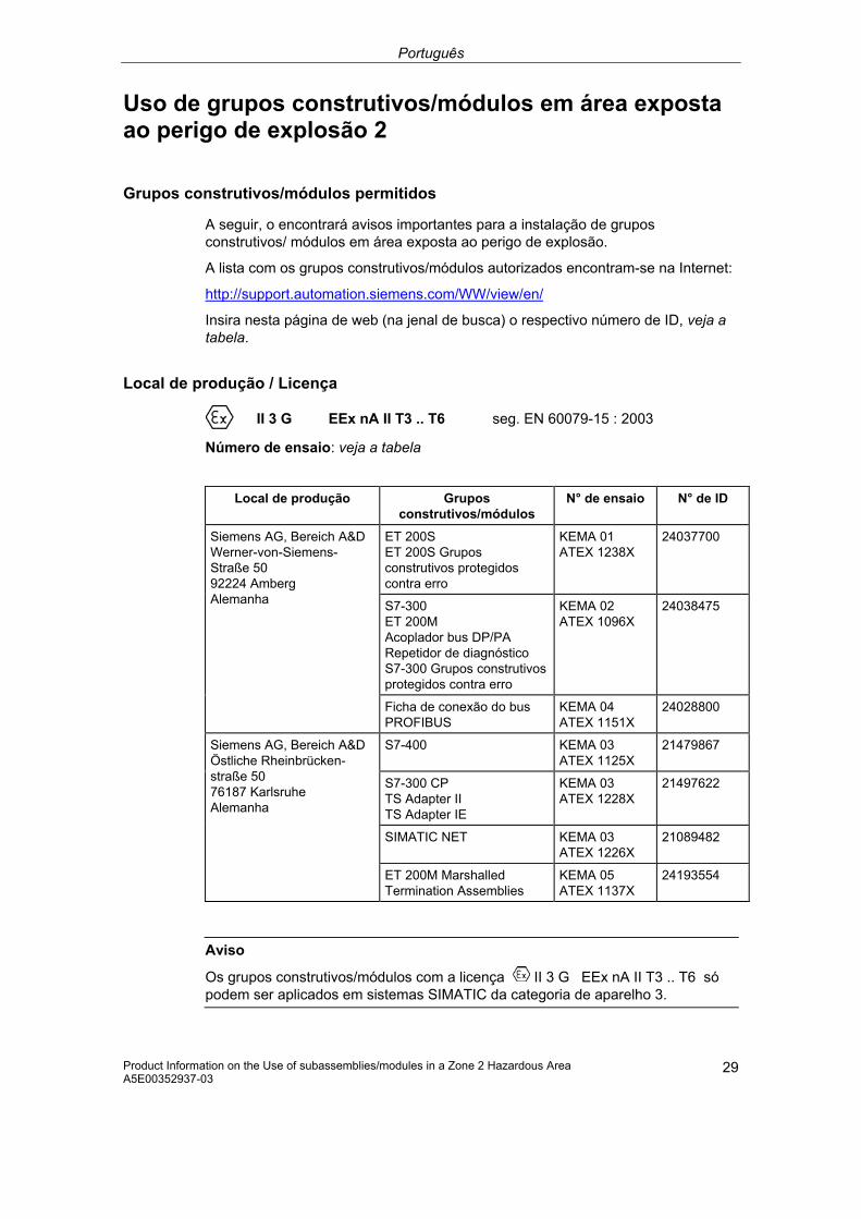
Português
Product Information on the Use of subassemblies/modules in a Zone 2 Hazardous Area A5E00352937-03
29
Uso de grupos construtivos/módulos em área exposta ao perigo de explosão 2
Grupos construtivos/módulos permitidos
A seguir, o encontrará avisos importantes para a instalação de grupos construtivos/ módulos em área exposta ao perigo de explosão.
A lista com os grupos construtivos/módulos autorizados encontram-se na Internet:
http://support.automation.siemens.com/WW/view/en/
Insira nesta página de web (na jenal de busca) o respectivo número de ID, veja a tabela.
Local de produção / Licença
II 3 G EEx nA II T3 .. T6 seg. EN 60079-15 : 2003
Número de ensaio: veja a tabela
Local de produção Grupos construtivos/módulos
N° de ensaio N° de ID
ET 200S ET 200S Grupos construtivos protegidos contra erro
KEMA 01 ATEX 1238X
24037700
S7-300 ET 200M Acoplador bus DP/PA Repetidor de diagnóstico S7-300 Grupos construtivos protegidos contra erro
KEMA 02 ATEX 1096X
24038475
Siemens AG, Bereich A&D Werner-von-Siemens-Straße 50 92224 Amberg Alemanha
Ficha de conexão do bus PROFIBUS
KEMA 04 ATEX 1151X
24028800
S7-400 KEMA 03 ATEX 1125X
21479867
S7-300 CP TS Adapter II TS Adapter IE
KEMA 03 ATEX 1228X
21497622
SIMATIC NET KEMA 03 ATEX 1226X
21089482
Siemens AG, Bereich A&D Östliche Rheinbrücken-straße 50 76187 Karlsruhe Alemanha
ET 200M Marshalled Termination Assemblies
KEMA 05 ATEX 1137X
24193554
Aviso
Os grupos construtivos/módulos com a licença II 3 G EEx nA II T3 .. T6 só podem ser aplicados em sistemas SIMATIC da categoria de aparelho 3.
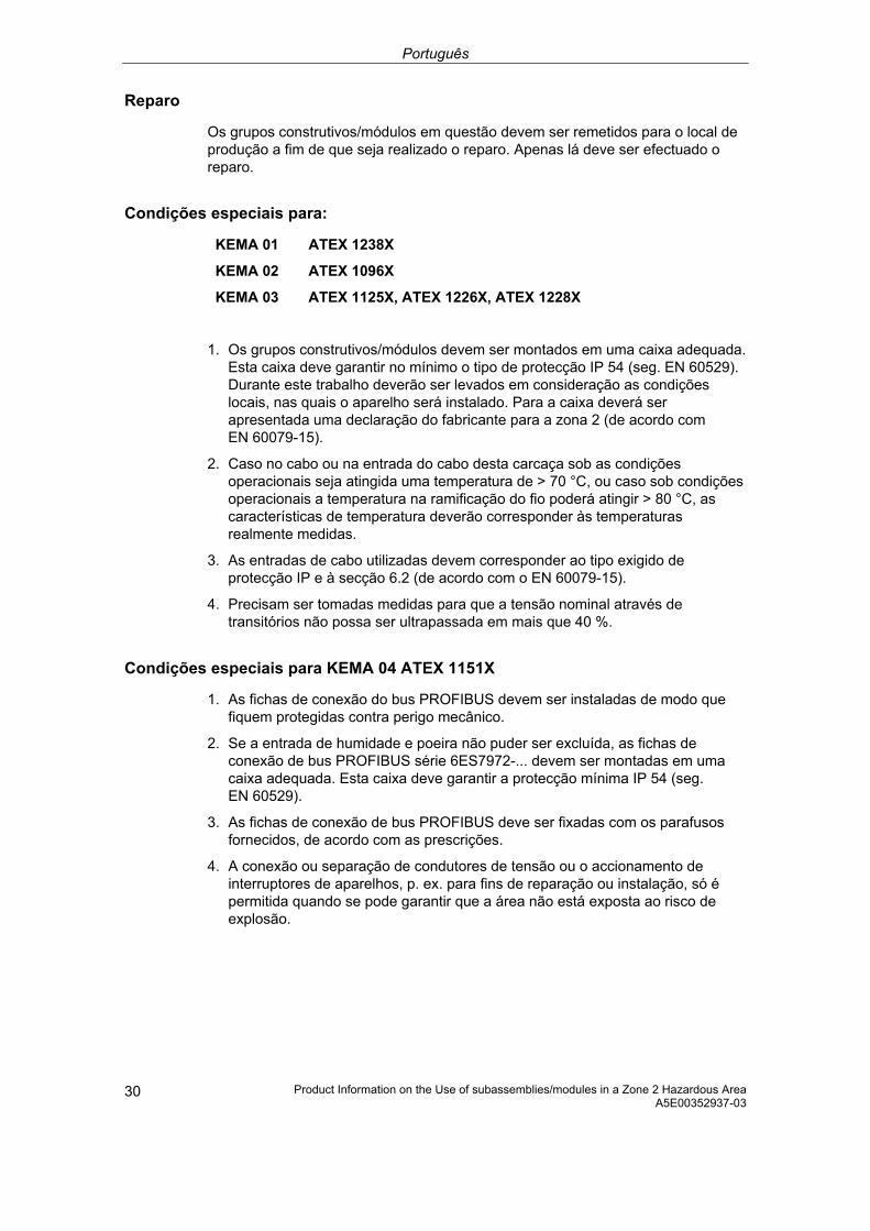
Português
Product Information on the Use of subassemblies/modules in a Zone 2 Hazardous Area A5E00352937-03
30
Reparo
Os grupos construtivos/módulos em questão devem ser remetidos para o local de produção a fim de que seja realizado o reparo. Apenas lá deve ser efectuado o reparo.
Condições especiais para:
KEMA 01 ATEX 1238X
KEMA 02 ATEX 1096X
KEMA 03 ATEX 1125X, ATEX 1226X, ATEX 1228X
1. Os grupos construtivos/módulos devem ser montados em uma caixa adequada. Esta caixa deve garantir no mínimo o tipo de protecção IP 54 (seg. EN 60529). Durante este trabalho deverão ser levados em consideração as condições locais, nas quais o aparelho será instalado. Para a caixa deverá ser apresentada uma declaração do fabricante para a zona 2 (de acordo com EN 60079-15).
2. Caso no cabo ou na entrada do cabo desta carcaça sob as condições operacionais seja atingida uma temperatura de > 70 °C, ou caso sob condições operacionais a temperatura na ramificação do fio poderá atingir > 80 °C, as características de temperatura deverão corresponder às temperaturas realmente medidas.
3. As entradas de cabo utilizadas devem corresponder ao tipo exigido de protecção IP e à secção 6.2 (de acordo com o EN 60079-15).
4. Precisam ser tomadas medidas para que a tensão nominal através de transitórios não possa ser ultrapassada em mais que 40 %.
Condições especiais para KEMA 04 ATEX 1151X
1. As fichas de conexão do bus PROFIBUS devem ser instaladas de modo que fiquem protegidas contra perigo mecânico.
2. Se a entrada de humidade e poeira não puder ser excluída, as fichas de conexão de bus PROFIBUS série 6ES7972-... devem ser montadas em uma caixa adequada. Esta caixa deve garantir a protecção mínima IP 54 (seg. EN 60529).
3. As fichas de conexão de bus PROFIBUS deve ser fixadas com os parafusos fornecidos, de acordo com as prescrições.
4. A conexão ou separação de condutores de tensão ou o accionamento de interruptores de aparelhos, p. ex. para fins de reparação ou instalação, só é permitida quando se pode garantir que a área não está exposta ao risco de explosão.

Português
Product Information on the Use of subassemblies/modules in a Zone 2 Hazardous Area A5E00352937-03
31
Condições especiais para KEMA 05 ATEX 1137X
1. Os grupos construtivos/módulos devem ser montados numa caixa adequada. Esta caixa deve garantir a protecção mínima IP 54 (seg. EN 60529). Para isso, as condições de ambiente, nas quais o aparelho é instalado, devem ser consideradas. Para a caixa, deve haver uma declaração do fabricante para a zona 2 (seg. EN 60079-15).
2. Se no cabo ou condutor do cabo desta caixa, sob condições de serviço, uma temperatura de > 70 °C for alcançada ou se, sob condições de serviço, a temperatura da derivação do condutor puder ser de > 80 °C, as características de temperatura dos cabos devem coincidir com as temperaturas reais medidas.
3. Precisam ser tomadas medidas para que a tensão nominal através de transitórios não possa ser ultrapassada em mais que 40 %.
Outras informações
Outras informações sobre os grupos construtivos/módulos podem ser encontradas no respectivo manual.
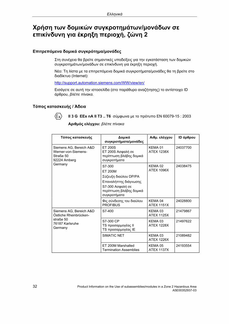
Ελληνικά
32 Product Information on the Use of subassemblies/modules in a Zone 2 Hazardous Area A5E00352937-03
Χρήση των δομικών συγκροτημάτων/μονάδων σε επικίνδυνη για έκρηξη περιοχή, ζώνη 2
Επιτρεπόμενα δομικά συγκρότημα/μονάδες
Στη συνέχεια θα βρείτε σημαντικές υποδείξεις για την εγκατάσταση των δομικών συγκροτημάτων/μονάδων σε επικίνδυνη για έκρηξη περιοχή.
Νέο: Τη λίστα με τα επιτρεπόμενα δομικά συγκροτήματα/μονάδες θα τη βρείτε στο διαδίκτυο (Internet):
http://support.automation.siemens.com/WW/view/en/
Εισάγετε σε αυτή την ιστοσελίδα (στο παράθυρο αναζήτησης) το αντίστοιχο ID άρθρου, βλέπε πίνακα.
Τόπος κατασκευής / Άδεια
II 3 G EEx nA II T3 .. T6 σύμφωνα με το πρότυπο EN 60079-15 : 2003
Αριθμός ελέγχου: βλέπε πίνακα
Τόπος κατασκευής Δομικά συγκροτήματα/μονάδες
Αιθμ. ελέγχου ID άρθρου
ET 200S ET 200S Ασφαλή σε περίπτωση βλάβης δομικά συγκροτήματα
KEMA 01 ATEX 1238X
24037700
S7-300 ET 200M Σύζευξη διαύλου DP/PA Επαναλήπτης διάγνωσης S7-300 Ασφαλή σε περίπτωση βλάβης δομικά συγκροτήματα
KEMA 02 ATEX 1096X
24038475
Siemens AG, Bereich A&D Werner-von-Siemens-Straße 50 92224 Amberg Germany
Φις σύνδεσης του διαύλου PROFIBUS
KEMA 04 ATEX 1151X
24028800
S7-400 KEMA 03 ATEX 1125X
21479867
S7-300 CP TS προσαρμογέας II TS προσαρμογέας IE
KEMA 03 ATEX 1228X
21497622
SIMATIC NET KEMA 03 ATEX 1226X
21089482
Siemens AG, Bereich A&D Östliche Rheinbrücken- straße 50 76187 Karlsruhe Germany
ET 200M Marshalled Termination Assemblies
KEMA 05 ATEX 1137X
24193554

Ελληνικά
Product Information on the Use of subassemblies/modules in a Zone 2 Hazardous Area 33 A5E00352937-03
Υπόδειξη
Δομικά συγκροτήματα/μονάδες με την έγκριση II 3 G EEx nA II T3 .. T6 επιτρέπεται να χρησιμοποιούνται μόνο σε συστήματα SIMATIC της κατηγορίας συσκευής 3
Συντήρηση
Για μια επισκευή πρέπει να σταλθούν τα αντίστοιχα δομικά συγκροτήματα/μονάδες στον τόπο κατασκευής. Μόνο εκεί επιτρέπεται να γίνει η επισκευή.
Ιδιαίτερες προϋποθέσεις για:
KEMA 01 ATEX 1238X
KEMA 02 ATEX 1096X
KEMA 03 ATEX 1125X, ATEX 1226X, ATEX 1228X
1. Τα δομικά συγκροτήματα/μονάδες πρέπει να ενσωματωθούν σε ένα γειωμένο περίβλημα. Αυτό το περίβλημα πρέπει να εξασφαλίζει το λιγότερο το βαθμό προστασίας IP 54 (κατά EN 60529). Σε αυτήν την περίπτωση πρέπει να ληφθούν υπόψη οι περιβαλλοντικές συνθήκες, στις οποίες θα εγκατασταθεί η συσκευή. Για το περίβλημα πρέπει να προβλέπεται δήλωση του κατασκευαστή για τη ζώνη 2 (σύμφωνα με το πρότυπο EN 60079-15).
2. Εάν στο καλώδιο ή στην είσοδο του καλωδίου αυτού του περιβλήματος κάτω από συνθήκες λειτουργίας η θερμοκρασία ξεπεράσει τους 70 °C ή όταν κάτω από συνθήκες λειτουργίας η θερμοκρασία στη διακλάδωση του σύρματος μπορεί να είναι μεγαλύτερη από 80 °C, πρέπει οι θερμοκρασιακές ιδιότητες των καλωδίων να ταυτίζονται με τις πραγματικά μετρημένες θερμοκρασίες.
3. Οι χρησιμοποιούμενες εισόδοι καλωδίων πρέπει να συμμορφώνονται με το βαθμό προστασίας IP 54 στην ενότητα 6.2 (σύμφωνα με το πρότυπο EN 60079-15).
4. Πρέπει να ληφθούν μέτρα, να μην μπορεί να γίνει υπέρβαση της ονομαστικής τάσης μέσω αιφνίδιας μεταβολής της τάσης πάνω από 40 %.
Ιδιαίτερες προϋποθέσεις για KEMA 04 ATEX 1151X
1. Τα φις σύνδεσης του διαύλου PROFIBUS πρέπει να εγκατασταθούν έτσι, ώστε να προστατεύονται από μηχανικό κίνδυνο.
2. Όταν η είσοδος υγρασίας και σκόνης δεν μπορεί να αποκλειστεί, τότε πρέπει τα φις σύνδεσης του διαύλου PROFIBUS σειρά 6ES7972-... να τοποθτηθούν σε ένα κατάλληλο περίβλημα. Αυτό το περίβλημα πρέπει να εξασφαλίζει το ελάχιστο το βαθμός προστασίας IP 54 (σύμφωνα με το πρότυπο EN 60529).
3. Τα φις σύνδεσης του διαύλου PROFIBUS πρέπει να στερεωθούν με τις συνημμένες βίδες σύμφωνα με τις προδιαγραφές.
4. Η σύνδεση ή η αποσύνδεση ηλεκτροφόρων αγωγών ή ο χειρισμός του διακόπτη της συσκευής, π.χ. για λόγους εγκατάστασης ή συντήρησης, επιτρέπεται μόνο, όταν είναι εξασφαλισμένο, ότι η περιοχή δεν είναι μια επικίνδυνη για έκρηξ περιοχή.

Ελληνικά
34 Product Information on the Use of subassemblies/modules in a Zone 2 Hazardous Area A5E00352937-03
Ιδιαίτερες προϋποθέσεις για KEMA 05 ATEX 1137X
1. Τα δομικά συγκροτήματα/μονάδες πρέπει να ενσωματωθούν σε ένα γειωμένο περίβλημα. Αυτό το περίβλημα πρέπει να εξασφαλίζει το λιγότερο το βαθμό προστασίας IP 54 (κατά EN 60529). Σε αυτήν την περίπτωση πρέπει να ληφθούν υπόψη οι περιβαλλοντικές συνθήκες, στις οποίες θα εγκατασταθεί η συσκευή. Για το περίβλημα πρέπει να προβλέπεται δήλωση του κατασκευαστή για τη ζώνη 2 (σύμφωνα με το πρότυπο EN 60079-15).
2. Εάν στο καλώδιο ή στην είσοδο του καλωδίου αυτού του περιβλήματος κάτω από συνθήκες λειτουργίας η θερμοκρασία ξεπεράσει τους 70 °C ή όταν κάτω από συνθήκες λειτουργίας η θερμοκρασία στη διακλάδωση του σύρματος μπορεί να είναι μεγαλύτερη από 80 °C, πρέπει οι θερμοκρασιακές ιδιότητες των καλωδίων να ταυτίζονται με τις πραγματικά μετρημένες θερμοκρασίες.
3. Πρέπει να ληφθούν μέτρα, να μην μπορεί να γίνει υπέρβαση της ονομαστικής τάσης μέσω αιφνίδιας μεταβολής της τάσης πάνω από 40 %.
Περισσότερες πληροφορίες
Περαιτέρω πληροφορίες για τα δομικά συγκροτήματα/μονάδες θα βρείτε στο αντίτοιχο εγχειρίδιο.

Česky
Product Information on the Use of subassemblies/modules in a Zone 2 Hazardous Area 35 A5E00352937-03
Použití konstrukčních skupin / modulů v prostředí s nebezpečím výbuchu Zóna 2
Schválené konstrukční skupiny/moduly
Dále naleznete důležité pokyny pro instalaci konstrukčních skupin/modulů v oblastech s nebezpečím výbuchu.
Seznam schválených konstrukčních skupin/modulů naleznete na internetu:
http://support.automation.siemens.com/WW/view/en/
Na této internetové stránce zadejte do vyhledávacího okna příslušné identifikační číslo příspěvku. Viz tabulka.
Místo výroby / Registrace
II 3 G EEx nA II T3 .. T6 dle EN 60079-15 : 2003
Zkušební číslo: viz tabulka
Místo výroby Konstrukční
skupiny/Moduly Kontrolní číslo ID příspěvku
ET 200S ET 200S Konstrukční skupiny odolné proti chybám
KEMA 01 ATEX 1238X
24037700
S7-300 ET 200M Spojka sběrnice DP/PA Diagnostické translační relé S7-300 Konstrukční skupiny odolné proti chybám
KEMA 02 ATEX 1096X
24038475
Siemens AG, Bereich A&D Werner-von-Siemens-Straße 50 92224 Amberg Germany
PROFIBUS-Busanschlussstecker
KEMA 04 ATEX 1151X
24028800
S7-400 KEMA 03 ATEX 1125X
21479867
S7-300 CP TS Adapter II TS Adapter IE
KEMA 03 ATEX 1228X
21497622
SIMATIC NET KEMA 03 ATEX 1226X
21089482
Siemens AG, Bereich A&D Östliche Rheinbrücken- straße 50 76187 Karlsruhe Germany
ET 200M Marshalled Termination Assemblies
KEMA 05 ATEX 1137X
24193554
Upozornění
Konstrukční skupiny/Moduly s osvědčením II 3 G EEx nA II T3 .. T6 smějí být použity pouze v systémech SIMATIC, přístrojové kategorie 3.
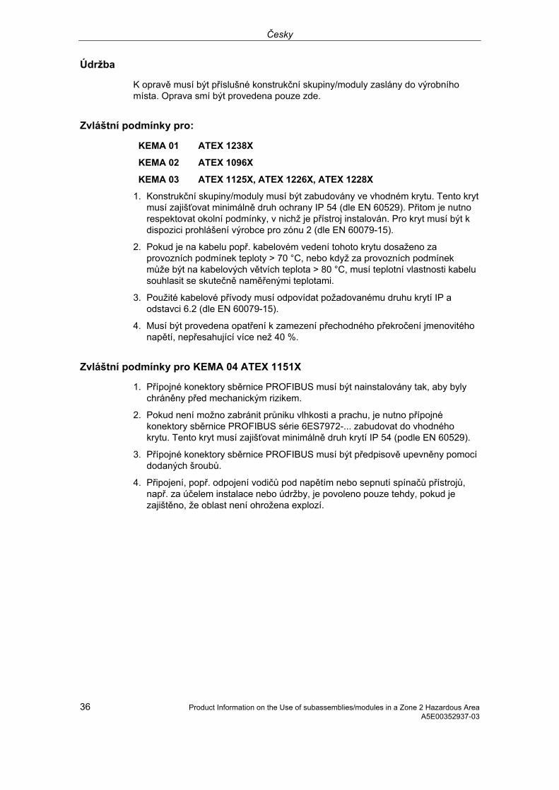
Česky
36 Product Information on the Use of subassemblies/modules in a Zone 2 Hazardous Area A5E00352937-03
Údržba
K opravě musí být příslušné konstrukční skupiny/moduly zaslány do výrobního místa. Oprava smí být provedena pouze zde.
Zvláštní podmínky pro:
KEMA 01 ATEX 1238X
KEMA 02 ATEX 1096X
KEMA 03 ATEX 1125X, ATEX 1226X, ATEX 1228X
1. Konstrukční skupiny/moduly musí být zabudovány ve vhodném krytu. Tento kryt musí zajišťovat minimálně druh ochrany IP 54 (dle EN 60529). Přitom je nutno respektovat okolní podmínky, v nichž je přístroj instalován. Pro kryt musí být k dispozici prohlášení výrobce pro zónu 2 (dle EN 60079-15).
2. Pokud je na kabelu popř. kabelovém vedení tohoto krytu dosaženo za provozních podmínek teploty > 70 °C, nebo když za provozních podmínek může být na kabelových větvích teplota > 80 °C, musí teplotní vlastnosti kabelu souhlasit se skutečně naměřenými teplotami.
3. Použité kabelové přívody musí odpovídat požadovanému druhu krytí IP a odstavci 6.2 (dle EN 60079-15).
4. Musí být provedena opatření k zamezení přechodného překročení jmenovitého napětí, nepřesahující více než 40 %.
Zvláštní podmínky pro KEMA 04 ATEX 1151X
1. Přípojné konektory sběrnice PROFIBUS musí být nainstalovány tak, aby byly chráněny před mechanickým rizikem.
2. Pokud není možno zabránit průniku vlhkosti a prachu, je nutno přípojné konektory sběrnice PROFIBUS série 6ES7972-... zabudovat do vhodného krytu. Tento kryt musí zajišťovat minimálně druh krytí IP 54 (podle EN 60529).
3. Přípojné konektory sběrnice PROFIBUS musí být předpisově upevněny pomocí dodaných šroubů.
4. Připojení, popř. odpojení vodičů pod napětím nebo sepnutí spínačů přístrojů, např. za účelem instalace nebo údržby, je povoleno pouze tehdy, pokud je zajištěno, že oblast není ohrožena explozí.

Česky
Product Information on the Use of subassemblies/modules in a Zone 2 Hazardous Area 37 A5E00352937-03
Zvláštní podmínky pro KEMA 05 ATEX 1137X
1. Konstrukční skupiny/moduly musí být zabudovány ve vhodném krytu. Tento kryt musí zajišťovat minimálně druh krytí IP 54 (podle EN 60529). Přitom je nutno respektovat okolní podmínky, v nichž je přístroj instalován. Pro kryt musí být k dispozici prohlášení výrobce pro zónu 2 (dle EN 60079-15).
2. Pokud je na kabelu popř. kabelovém vedení tohoto krytu dosaženo za provozních podmínek teploty > 70 °C, nebo když za provozních podmínek může být na kabelových větvích teplota > 80 °C, musí teplotní vlastnosti kabelu souhlasit se skutečně naměřenými teplotami.
3. Musí být provedena opatření k zamezení přechodného překročení jmenovitého napětí, nepřesahující více než 40 %.
Další informace
Další informace ke konstrukčním skupinám/modulům naleznete v příslušné příručce.

Estnisch
38 Product Information on the Use of subassemblies/modules in a Zone 2 Hazardous Area A5E00352937-03
Sõlmede/moodulite kasutamine plahvatusohtliku piirkonna tsoonis 2
Lubatud sõlmed/moodulid
Järgnevalt leiate Te olulisi juhiseid sõlmede/moodulite paigaldamiseks plahvatusohtlikus piirkonnas.
Üksikasjaliku teabe lubatud sõlmede/moodulite kohta leiate Internetist: http://support.automation.siemens.com/WW/view/en/
Sisestage sellel veebilehel (otsinguaknasse) vastav kood, vt tabelit.
Valmistamiskoht / Kasutusluba
II 3 G EEx nA II T3 .. T6 vastavalt standardile 60079-15 : 2003
Katsetusnumber: vaadake tabelit
Valmistamiskoht Sõlmed/moodulid Katsetusnumber Kood
ET 200S ET 200S rikkekindlad moodulid
KEMA 01 ATEX 1238X
24037700
S7-300 ET 200M siiniühendus DP/PA diagnostikarepiiter S7-300 rikkekindlad sõlmed
KEMA 02 ATEX 1096X
24038475
Siemens AG, Bereich A&D Werner-von-Siemens-Straße 50 92224 Amberg Germany
PROFIBUS-siiniühenduse pistik KEMA 04 ATEX 1151X
24028800
S7-400 KEMA 03 ATEX 1125X
21479867
S7-300 CP TS adapter II TS adapter IE
KEMA 03 ATEX 1228X
21497622
SIMATIC NET KEMA 03 ATEX 1226X
21089482
Siemens AG, Bereich A&D Östliche Rheinbrücken- straße 50, 76187 Karlsruhe Germany
ET 200M juhitavad klemmliideste sõlmed
KEMA 05 ATEX 1137X
24193554
Juhis
Sõlmi/mooduleid kasutusloaga II 3 G EEx nA II T3 .. T6 tohib kasutada ainult SIMATIC-süsteemides, mille seadmeklass on 3.

Estnisch
Product Information on the Use of subassemblies/modules in a Zone 2 Hazardous Area 39 A5E00352937-03
Korrashoid
Parandamiseks tuleb sõlmed/moodulid saata valmistamiskohta. Parandustöid tohib teha ainult seal.
Eritingimused
KEMA 01 ATEX 1238X
KEMA 02 ATEX 1096X
KEMA 03 ATEX 1125X, ATEX 1226X, ATEX 1228X
kohta:
1. Sõlmed/moodulid tuleb monteerida sobivasse metallkorpusesse. Korpus peab tagama kaitseastme vähemalt IP 54 (vastavalt standardile EN 60529). Seejuures peab arvesse võtma seadme paigaldamise keskkonna tingimusi. Korpuse jaoks peab tsooni 2 jaoks olema tootja juhis (vastavalt standardile EN 60079-15).
2. Kui selle korpuse kaabli juures või kaabelvaheliku (kaabelsisestuse) juures töötingimustes saavutatakse temperatuur > 70 °C või, kui töötingimustes temperatuur soone hargnemiskoha juures võib olla > 80 °C, peavad kaabli termilised omadused olema vastavuses tegelikult mõõdetud temperatuuridega.
3. Kasutatavad kaabelvahelikud (kaabelsisestused) peavad vastama nõutud IP-kaitseastmele ja osas 6.2 toodud nõuetele (vastavalt standardile EN 60079-15).
4. Peab rakendama abinõusid, et nimipinget üleminekute tõttu ei saaks ületada üle 40 %.
Eritingimused KEMA 04 ATEX 1151X kohta
1. PROFIBUS-siiniühenduse pistik tuleb paigaldada selliselt, et see oleks kaitstud mehaanilise ohu eest.
2. Juhul kui niiskuse ja tolmu sissetungimist ei saa vältida, tuleb 6ES7972-... seeria PROFIBUS-siiniühenduse pistikud paigaldada sobivasse korpusesse. See korpus peab tagama vähemalt kaitseklassile IP 54 (vastavalt standardile EN 60529).
3. PROFIBUS-siiniühenduse pistikud tuleb kinnitada ettenähtud viisil kaasasolevate kruvidega.
4. Pinget juhtivate juhtide ühendamine või eemaldamine või seadme lüliti käivitamine, nt paigaldus- ja hoolduseesmärkidel, on lubatud ainult juhul, kui piirkond ei ole plahvatusohtlik.

Estnisch
40 Product Information on the Use of subassemblies/modules in a Zone 2 Hazardous Area A5E00352937-03
Eritingimused KEMA 05 ATEX 1137X kohta
1. Sõlmed/moodulid tuleb monteerida sobivasse metallkorpusesse. Korpus peab tagama kaitseastme vähemalt IP 54 (vastavalt standardile EN 60529). Seejuures peab arvesse võtma seadme paigaldamise keskkonna tingimusi. Korpuse jaoks peab tsooni 2 jaoks olema tootja juhis (vastavalt standardile EN 60079-15).
2. Kui selle korpuse kaabli juures või kaabelvaheliku (kaabelsisestuse) juures töötingimustes saavutatakse temperatuur > 70 °C või, kui töötingimustes temperatuur soone hargnemiskoha juures võib olla > 80 °C, peavad kaabli termilised omadused olema vastavuses tegelikult mõõdetud temperatuuridega.
3. Peab rakendama abinõusid, et nimipinget üleminekute tõttu ei saaks ületada üle 40 %.
Täpsem teave
Täpsemat teavet sõlmede/moodulite kohta leiate kaasasolevast käsiraamatust.

Latviski
Product Information on the Use of subassemblies/modules in a Zone 2 Hazardous Area 41 A5E00352937-03
Ierīču/moduļu pielietojums sprādzienbīstamas teritorijas zonā 2
Pieļaujamās ierīces/moduļi
Turpmāk atrodamas svarīgas norādes par ierīču/moduļu uzstādīšanu sprādzienbīstamajā zonā.
Sarakstu ar pieļaujamajām ierīcēm/moduļiem Jūs atradīsiet internetā:
http://support.automation.siemens.com/WW/view/en/
Ievadiet šajā mājas lapā (meklēšanas logā) attiecīgo lietotāja ID, skatīt tabulu
Izgatavošanas vieta / Atļauja
II 3 G EEx nA II T3 .. T6 saskaņā ar EN 60079-15 : 2003
Pārbaudes numurs: skatīt tabulu
Izgatavošanas vieta Ierīces/moduļi Pārbaudes
numurs Lietotāja ID
ET 200S ET 200S Fehlersichere Module
KEMA 01 ATEX 1238X
24037700
S7-300 ET 200M Kopnes savienotājs DP/PA Diagnostikas atkārtotājs S7-300 Pret kļūdām aizsargātas ierīces
KEMA 02 ATEX 1096X
24038475
Siemens AG, Bereich A&D Werner-von-Siemens-Straße 50 92224 Amberg Germany
PROFIBUS slēdzis
KEMA 04 ATEX 1151X
24028800
S7-400 KEMA 03 ATEX 1125X
21479867
S7-300 CP TS Adapter II TS Adapter IE
KEMA 03 ATEX 1228X
21497622
SIMATIC NET KEMA 03 ATEX 1226X
21089482
Siemens AG, Bereich A&D Östliche Rheinbrücken- straße 50 76187 Karlsruhe Germany
ET 200M Marshalled Termination Assemblies
KEMA 05 ATEX 1137X
24193554

Latviski
42 Product Information on the Use of subassemblies/modules in a Zone 2 Hazardous Area A5E00352937-03
Norāde
Ierīces/moduļi ar atļauju II 3 G EEx nA II T3 .. T6 var tikt pielietotas tikai 3.kategorijas SIMATIC sistēmās.
Tehniskā apkope
Attiecīgu ierīču/moduļu remontam tie ir jānosūta ražotājam. Remontu drīkst veikt tikai tur.
Īpaši apstākļi priekš
KEMA 01 ATEX 1238X
KEMA 02 ATEX 1096X
KEMA 03 ATEX 1125X, ATEX 1226X, ATEX 1228X
1. Ierīces/moduļi jāiebūvē piemērotā metāla korpusā. Tiem jānodrošina aizsardzības līmenis ne mazāks kā IP 54 (saskaņā ar EN 60529). Turklāt, ierīces uzstādīšanā jāievēro apkārtējas vides apstākļi. Korpusam ir nepieciešams izgatavotāja apliecinājums zonai 2 (saskaņā ar EN 60079-15).
2. Ja uz kabeļa vai šī korpusa kabeļu ievades ekspluatācijas apstākļos tiek sasniegta temperatūra > 70 °C vai ja ekspluatācijas apstākļos uz kabeļa atzariem var būt temperatūra > 80 °C, kabeļu temperatūras īpašībām jāatbilst faktiski nomērītām temperatūrām.
3. Pielietojamām kabeļu ievadēm jāatbilst nepieciešamajam aizsardzības veidam IP un sadaļai 6.2 (saskaņā ar EN 60079-15).
4. Nepieciešams veikt pasākumus, lai pārejas spriegums nepārsniegtu nominālo spriegumu vairāk kā par 40 %.
Īpašie noteikumi KEMA 04 ATEX 1151X 1. PROFIBUS slēdžus ir jāinstalē tā, lai tie būtu aizsargāti no mehāniskām
briesmām
2. Ja nav iespējams izvairīties no šķidrumu un putekļu iekļūšanas, tad PROFIBUS slēdžus no sērijas 6ES7972-... ir jāiebūvē piemērotā korpusā. Šim korpusam ir jāatbalsta vismaz drošības veids IP 54 (pēc E N 60529).
3. PROFIBUS slēdžus ir jāpiestiprina ar komplektā ietilpstošajām skrūvēm.
4. Spriegumu vadošu vadu pieslēgšana vai atslēgšana vai ierīces slēdža lietošana, piemēram, uzstādīšanas vai tehniskās apkopes dēļ, ir atļauta tikai tad, kad ir noskaidrots vai zonā nepastāv eksplodēšanas iespējamība.

Latviski
Product Information on the Use of subassemblies/modules in a Zone 2 Hazardous Area 43 A5E00352937-03
Īpaši noteikumi KEMA 05 ATEX 1137X
1. Ierīces/moduļi ir jāiebūvē piemērotā korpusā. Šiem korpusiem ir jāatbalsta vismaz drošības veids IP 54 (pēc E N 60529). Pie tam ir jāņem vērā apkārtnes faktori, kādā ierīce tiks uzstādīta. Korpusam jāatbilst ražotāja 2. zonas deklarācijai (saskaņā ar EN 60079-15).
2. Ja šī korpusa kabelis, respektīvi, kabeļa ievade darba laikā sasniedz > 70 °C vai, ja darba laikā vadu sazarojums ir sasniedzis > 80 °C, tad kabeļa temperatūras īpašībām ir jāatbilst izmērītajām temperatūrām.
3. Ir jāveic pasākumi, lai nominālais spriegums caur pārejām nepārsniegtu 40%
Papildus informācija Papildus informāciju par ierīcēm/moduļiem Jūs atradīsiet pievienotajā rokasgrāmatā.

Lietuviška
44 Product Information on the Use of subassemblies/modules in a Zone 2 Hazardous Area A5E00352937-03
Konstrukcinių grupių / modulių panaudojimas sprogioje 2 zonos aplinkoje
Leistinos konstrukcinės grupės / moduliai
Toliau pateikiama svarbi informacija apie konstrukcinių grupių ir modulių montavimą sprogioje aplinkoje.
Leistinų konstrukcinių grupių / modulių sąrašą rasite interneto svetainėje:
http://support.automation.siemens.com/WW/view/en/
Įveskite šioje svetainėje (į ieškos laukelį) atitinkamą kodą, žr. lentelę.
Pagaminimo vieta / Saugos reikalavimai
II 3 G EEx nA II T3 .. T6 pagal EN 60079-15 : 2003
Patikros numeris: žr. lentelėje
Pagaminimo vieta Konstrukcinės grupės /
moduliai Patikros numeris
Kodas
ET 200S ET 200S nuo trukdžių apsaugotos konstrukcinės grupės
KEMA 01 ATEX 1238X
24037700
S7-300 ET 200M Magistralinė jungtis DP/PA Diagnozės retransliatorius S7-300 nuo trukdžių apsaugotos konstrukcinės grupės
KEMA 02 ATEX 1096X
24038475
Siemens AG, Bereich A&D Werner-von-Siemens-Straße 50 92224 Ambergas Vokietija
PROFIBUS magistralinės jungties kištukas
KEMA 04 ATEX 1151X
24028800
S7-400 KEMA 03 ATEX 1125X
21479867
S7-300 CP TS Adapter II TS Adapter IE
KEMA 03 ATEX 1228X
21497622
SIMATIC NET KEMA 03 ATEX 1226X
21089482
Siemens AG, Bereich A&D Östliche Rheinbrücken- straße 50 76187 Karlsruhe Vokietija
ET 200M Marshalled Termination Assemblies
KEMA 05 ATEX 1137X
24193554
Nuoroda
Konstrukcines grupes / modulius, kurių leidimas eksploatuoti yra II 3 G EEx nA II T3 .. T6, galima naudoti tik 3 kategorijos sistemose „SIMATIC“.
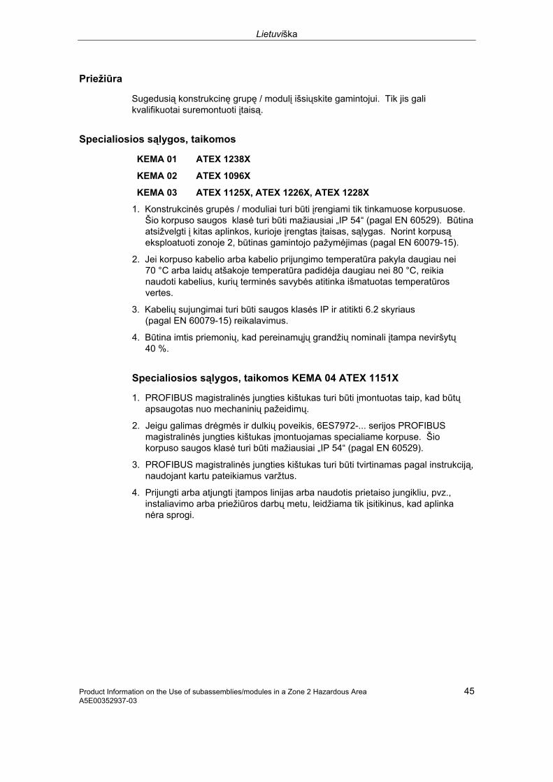
Lietuviška
Product Information on the Use of subassemblies/modules in a Zone 2 Hazardous Area 45 A5E00352937-03
Priežiūra
Sugedusią konstrukcinę grupę / modulį išsiųskite gamintojui. Tik jis gali kvalifikuotai suremontuoti įtaisą.
Specialiosios sąlygos, taikomos
KEMA 01 ATEX 1238X
KEMA 02 ATEX 1096X
KEMA 03 ATEX 1125X, ATEX 1226X, ATEX 1228X
1. Konstrukcinės grupės / moduliai turi būti įrengiami tik tinkamuose korpusuose. Šio korpuso saugos klasė turi būti mažiausiai „IP 54“ (pagal EN 60529). Būtina atsižvelgti į kitas aplinkos, kurioje įrengtas įtaisas, sąlygas. Norint korpusą eksploatuoti zonoje 2, būtinas gamintojo pažymėjimas (pagal EN 60079-15).
2. Jei korpuso kabelio arba kabelio prijungimo temperatūra pakyla daugiau nei 70 °C arba laidų atšakoje temperatūra padidėja daugiau nei 80 °C, reikia naudoti kabelius, kurių terminės savybės atitinka išmatuotas temperatūros vertes.
3. Kabelių sujungimai turi būti saugos klasės IP ir atitikti 6.2 skyriaus (pagal EN 60079-15) reikalavimus.
4. Būtina imtis priemonių, kad pereinamųjų grandžių nominali įtampa neviršytų 40 %.
Specialiosios sąlygos, taikomos KEMA 04 ATEX 1151X
1. PROFIBUS magistralinės jungties kištukas turi būti įmontuotas taip, kad būtų apsaugotas nuo mechaninių pažeidimų.
2. Jeigu galimas drėgmės ir dulkių poveikis, 6ES7972-... serijos PROFIBUS magistralinės jungties kištukas įmontuojamas specialiame korpuse. Šio korpuso saugos klasė turi būti mažiausiai „IP 54“ (pagal EN 60529).
3. PROFIBUS magistralinės jungties kištukas turi būti tvirtinamas pagal instrukciją, naudojant kartu pateikiamus varžtus.
4. Prijungti arba atjungti įtampos linijas arba naudotis prietaiso jungikliu, pvz., instaliavimo arba priežiūros darbų metu, leidžiama tik įsitikinus, kad aplinka nėra sprogi.

Lietuviška
46 Product Information on the Use of subassemblies/modules in a Zone 2 Hazardous Area A5E00352937-03
Specialiosios sąlygos, taikomos KEMA 05 ATEX 1137X
1. Konstrukcinės grupės / moduliai turi būti įrengiami tik tinkamuose korpusuose. Šio korpuso saugos klasė turi būti mažiausiai „IP 54“ (pagal EN 60529). Būtina atsižvelgti į kitas aplinkos, kurioje įrengtas įtaisas, sąlygas. Norint korpusą eksploatuoti zonoje 2, būtinas gamintojo pažymėjimas (pagal EN 60079-15).
2. Jei korpuso kabelio arba kabelio prijungimo temperatūra pakyla daugiau nei 70 °C arba laidų atšakoje temperatūra padidėja daugiau nei 80 °C, reikia naudoti kabelius, kurių terminės savybės atitinka išmatuotas temperatūros vertes.
3. Būtina imtis priemonių, kad pereinamųjų grandžių nominali įtampa neviršytų 40 %.
Papildoma informacija
Papildomos informacijos apie konstrukcines grupes / modulius rasite eksploatacijos vadove.

Magyar
Product Information on the Use of subassemblies/modules in a Zone 2 Hazardous Area 47 A5E00352937-03
A főegységek/modulok alkalmazása a 2. zóna robbanásveszélyes környezetben
Engedélyezett főegységek/modulok A következőkben fontos utasításokat talál a főegységek/modulok telepítéséhez a robbanásveszélyes környezetbe.
Az engedélyezett főegységek/modulok jegyzékét megtalálja az Interneten:
http://support.automation.siemens.com/WW/view/en/
Ezen a web-oldalon írja be a kereső ablakba a hozzá tartozó bejegyzés ID-t, ld. a táblázatban.
Gyártási hely / Engedélyezés
II 3 G EEx nA II T3 .. T6 az EN 60079-15 : 2003 szerint
Ellenőrző szám: lásd a táblázatot
Gyártási hely Főegységek/modulok Bevizsgálás
száma Bejegyzés
száma
ET 200S ET 200S hibabiztos főegységek
KEMA 01 ATEX 1238X
24037700
S7-300 ET 200M DP/PA buszcsatoló Diagnózisrepeater S7-300 hibabiztos főegységek
KEMA 02 ATEX 1096X
24038475
Siemens AG, Bereich A&DWerner-von-Siemens-Straße 50 92224 Amberg Germany
PROFIBUS- busz csatlakozó dugó
KEMA 04 ATEX 1151X
24028800
S7-400 KEMA 03 ATEX 1125X
21479867
S7-300 CP TS Adapter II TS Adapter IE
KEMA 03 ATEX 1228X
21497622
SIMATIC NET KEMA 03 ATEX 1226X
21089482
Siemens AG, Bereich A&DÖstliche Rheinbrücken- straße 50 76187 KarlsruheGermany
ET 200M Marshalled Termination Assemblies
KEMA 05 ATEX 1137X
24193554
Utasítás
Csak a II 3 G EEx nA II T3 .. T6 engedélyezéssel rendelkező főegységeket/modulokat használhatja a 3. felszerelés-kategóriába tartozó SIMATIC rendszerekbe.
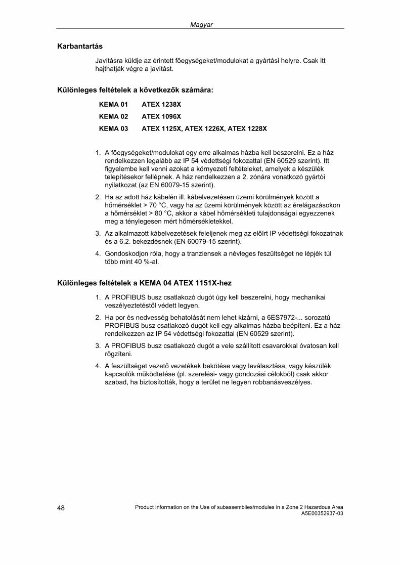
Magyar
Product Information on the Use of subassemblies/modules in a Zone 2 Hazardous Area A5E00352937-03 48
Karbantartás
Javításra küldje az érintett főegységeket/modulokat a gyártási helyre. Csak itt hajthatják végre a javítást.
Különleges feltételek a következők számára:
KEMA 01 ATEX 1238X
KEMA 02 ATEX 1096X
KEMA 03 ATEX 1125X, ATEX 1226X, ATEX 1228X
1. A főegységeket/modulokat egy erre alkalmas házba kell beszerelni. Ez a ház rendelkezzen legalább az IP 54 védettségi fokozattal (EN 60529 szerint). Itt figyelembe kell venni azokat a környezeti feltételeket, amelyek a készülék telepítésekor fellépnek. A ház rendelkezzen a 2. zónára vonatkozó gyártói nyilatkozat (az EN 60079-15 szerint).
2. Ha az adott ház kábelén ill. kábelvezetésen üzemi körülmények között a hőmérséklet > 70 °C, vagy ha az üzemi körülmények között az érelágazásokon a hőmérséklet > 80 °C, akkor a kábel hőmérsékleti tulajdonságai egyezzenek meg a ténylegesen mért hőmérsékletekkel.
3. Az alkalmazott kábelvezetések feleljenek meg az előírt IP védettségi fokozatnak és a 6.2. bekezdésnek (EN 60079-15 szerint).
4. Gondoskodjon róla, hogy a tranziensek a névleges feszültséget ne lépjék túl több mint 40 %-al.
Különleges feltételek a KEMA 04 ATEX 1151X-hez
1. A PROFIBUS busz csatlakozó dugót úgy kell beszerelni, hogy mechanikai veszélyeztetéstől védett legyen.
2. Ha por és nedvesség behatolását nem lehet kizárni, a 6ES7972-... sorozatú PROFIBUS busz csatlakozó dugót kell egy alkalmas házba beépíteni. Ez a ház rendelkezzen az IP 54 védettségi fokozattal (EN 60529 szerint).
3. A PROFIBUS busz csatlakozó dugót a vele szállított csavarokkal óvatosan kell rögzíteni.
4. A feszültséget vezető vezetékek bekötése vagy leválasztása, vagy készülék kapcsolók működtetése (pl. szerelési- vagy gondozási célokból) csak akkor szabad, ha biztosították, hogy a terület ne legyen robbanásveszélyes.

Magyar
Product Information on the Use of subassemblies/modules in a Zone 2 Hazardous Area 49 A5E00352937-03
Különleges feltételek a KEMA 05 ATEX 1137X-hez
1. A főegységeket/modulokat egy erre alkalmas házba kell beszerelni. Ez a ház rendelkezzen legalább az IP 54 védettségi fokozattal (EN 60529 szerint). Itt figyelembe kell venni azokat a környezeti feltételeket, amelyek a készülék telepítésekor fellépnek. A ház rendelkezzen a 2. zónára vonatkozó gyártói nyilatkozat (az EN 60079-15 szerint).
2. Ha a jelen ház kábelén ill. kábelvezetésen üzemi körülmények között a hőmérséklet > 70 °C, vagy ha az üzemi körülmények között az érelágazásokon a hőmérséklet > 80 °C, akkor a kábel hőmérsékleti tulajdonságai legyen azonosak a ténylegesen mért hőmérsékletekkel.
3. Gondoskodjon róla, hogy a tranziensek ne lépjék túl több mint 40 %-al a névleges feszültséget.
További információk
A főegységek/modulokról további információkat talál a hozzá tartozó kézikönyvben.

Malti
Product Information on the Use of subassemblies/modules in a Zone 2 Hazardous Area A5E00352937-03 50
Tqegħid tal-Komponenti / Modules fiż-Żona 2, fejn hemm Riskju ta' Splużjoni
Komponenti/Moduli approvati
Hawn taħt għandek issib indikazzjonijiet importanti għall-installazzjoni ta' komponenti / modules f’żona fejn hemm riskju ta' splużjoni.
Ġdid: Tista’ tara l-lista ta’ komponenti/modules approvati fuq l-internet:
http://support.automation.siemens.com/WW/view/en/
Daħħal fis-search window ta’ din il-websajt l-ID rispettiv ta’ l-oġġett, ara t-tabella.
Post ta' Manifattura / Approvazzjoni
II 3 G EEx nA II T3 .. T6 b’mod konformi ma’ EN 60079-15 : 2003
Numru taċ-Ċertifikat: ara t-tabella
Post ta' Manifattura Komponenti / Modules Numru taċ-
Ċertifikat Numru taċ-Ċertifikat
ET 200S Modules ET 200S fail-safe
KEMA 01 ATEX 1238X
24037700
S7-300 ET 200M bus coupling DP/PA Ripetitur ta' dijanjosi Modules S7-300 fail-safe
KEMA 02 ATEX 1096X
24038475
Siemens AG, Bereich A&D Werner-von-Siemens-Straße 5092224 Amberg Il-Ġermanja
PROFIBUS-Bus Connector Plug
KEMA 04 ATEX 1151X
24028800
S7-400 KEMA 03 ATEX 1125X
21479867
S7-300 CP TS Adapter TS Adaptor IE
KEMA 03 ATEX 1228X
21497622
SIMATIC NET KEMA 03 ATEX 1226X
21089482
Siemens AG, Bereich A&D Östliche Rheinbrücken- straße 50 76187 Karlsruhe Il-Ġermanja
ET 200M Marshalled Terminal Assemblies
KEMA 05 ATEX 1137X
24193554
Nota
Komponenti / modules approvati II 3 G EEx nA II T3 .. T6 jistgħu jintużaw biss f’sistemi SIMATIC li jappartienu għal appart ta’ kategorija 3.

Malti
Product Information on the Use of subassemblies/modules in a Zone 2 Hazardous Area 51 A5E00352937-03
Manutenzjoni
Fil-każ li jkollhom bżonn tiswija, il-komponenti / modules ikkonċernati għandhom jintbagħtu fil-post ta' manifattura. It-tiswijiet jistgħu jsiru biss f'dan il-post.
Kundizzjonijiet Speċjali għal:
KEMA 01 ATEX 1238X
KEMA 02 ATEX 1096X
KEMA 03 ATEX 1125X, ATEX 1226X, ATEX 1228X
1. Komponenti / modules għandhom jiġu mmontati ġewwa lqugħ addattat. Dan l-ilqugħ għandu jiggarantixxi protezzjoni li tkun mill-inqas tat-tip IP 54 (skond EN 60529). Inti u tagħmel hekk, trid taħseb għall-kundizzjonijiet ambjentali ta' waqt l-installazzjoni ta’ l-apparat. Għall-ilqugħ, irid ikun hemm dikjarazzjoni tal-fabbrikant li tgħid li dan huwa tajjeb għaż-żona 2 (skond EN 60079-15).
2. Jekk fil-kejbil, jew fil-kaxxa mad-daħla għall-kejbil, tintlaħaq temperatura ta' aktar minn 70 °C taħt kundizzjonijiet ta' ħidma, jew jekk fil-post fejn jinfirdu l-wajers jista' jkun hemm temperatura ogħla minn 80 °C, il-kejbil irid ikollu karatteristiċi li jifilħu għal dawn it-temperaturi.
3. Id-daħliet għall-kejbil li jintużaw iridu jikkonformaw mat-tip ta' protezzjoni IP mitluba u mat-taqsima 6.2 (skond EN 60079-15).
4. Iridu jittieħdu miżuri biex il-vultaġġ nominali ma jinqabiżx b'aktar minn 40%.
Kundizzjonijiet speċjali għal KEMA 04 ATEX 1151X
1. Il-plugs tat-tip PROFIBUS-Bus Connector jeħtieġu jiġu installati b’mod li jiżgura protezzjoni kontra kull periklu mekkaniku.
2. Jekk id-dħul ta’ l-umdità jew tat-trab ma jistax jiġi eskluż, jeħtieġu jiġu installati plugs tat-tip PROFIBUS-Bus Connector tan-Numru Serjali 6ES7972-... f’ilqugħ adegwat. Dan l-ilqugħ jeħtieġ jissodisfa l-klassi ta’ protezzjoni IP 54 (b’mod konformi ma’ EN 60529) bħala standard minimu.
3. Il-plugs tat-tip PROFIBUS-Connector jeħtieġu jiġu installati skond l-istruzzjonijiet u bil-viti pprovduti.
4. It-tqabbid u/jew skonnettjar ta’ wajers bil-kurrent fihom u l-użu ta’ swiċċijiet, jiġifieri għal għanijiet ta’ installazzjoni jew manutenzjoni huwa permess biss jekk iż-żona m’hijiex waħda li fiha riskju ta’ splużjoni.
Malti
Product Information on the Use of subassemblies/modules in a Zone 2 Hazardous Area A5E00352937-03 52
Kundizzjonijiet speċjali għal KEMA 05 ATEX 1137X
1. Komponenti / modules għandhom jiġu mmontati ġewwa lqugħ addattat. Dan l-ilqugħ għandu jiggarantixxi protezzjoni li tkun mill-inqas tat-tip IP 54 (skond EN 60529). Inti u tagħmel hekk, trid taħseb għall-kundizzjonijiet ambjentali ta' waqt l-installazzjoni ta’ l-apparat. Għall-ilqugħ, irid ikun hemm dikjarazzjoni tal-fabbrikant li tgħid li dan huwa tajjeb għaż-żona 2 (skond EN 60079-15).
2. Jekk fil-kejbil, jew fil-kaxxa mad-daħla għall-kejbil, tintlaħaq temperatura ta' aktar minn 70 °C taħt kundizzjonijiet ta' ħidma, jew jekk fil-post fejn jinfirdu l-wajers jista' jkun hemm temperatura ogħla minn 80 °C, il-kejbil irid ikollu karatteristiċi li jifilħu għal dawn it-temperaturi.
3. Iridu jittieħdu miżuri biex il-vultaġġ nominali ma jinqabiżx b'aktar minn 40%.
Aktar informazzjoni
Għal iktar informazzjoni dwar il-komponenti/moduli, jekk jogħġbok irreferi għall-manwal rispettiv.

Polski
Product Information on the Use of subassemblies/modules in a Zone 2 Hazardous Area 53 A5E00352937-03
Zastosowanie grup konstrukcyjnych / modułów w 2 strefie zagrożenia wybuchem
Dopuszczone grupy konstrukcyjne/moduły
Poniżej znajdują się ważne informacje dotyczące instalacji grup konstrukcyjnych modułów w strefie zagrożenia wybuchem.
Lista dopuszczonych grup konstrukcyjnych/modułów znajduje się w Internecie pod adresem http://support.automation.siemens.com/WW/view/en/
Na tej stronie należy wprowadzić odpowiedni ID udziału, patrz tabela.
Miejsce produkcji / Rejestracja
II 3 G EEx nA II T3 .. T6 stosownie do EN 60079-15 : 2003
Nr testu: zobacz tabela
Miejsce produkcji Grupy konstrukcyjne/moduły
Nr testu ID udziału
ET 200S ET 200S moduły odporne na uszkodzenia
KEMA 01 ATEX 1238X
24037700
S7-300 ET 200M Zbierające łącze sprzężające DP/PA Powtarzacz diagnozy S7-300 grupy odporne na uszkodzenia
KEMA 02 ATEX 1096X
24038475
Siemens AG, Bereich A&D Werner-von-Siemens-Straße 50 92224 Amberg Niemcy
PROFIBUS-szynowy wtyk przyłączeniowy
KEMA 04 ATEX 1151X
24028800
S7-400 KEMA 03 ATEX 1125X
21479867
S7-300 CP TS Adapter II TS Adapter IE
KEMA 03 ATEX 1228X
21497622
SIMATIC NET KEMA 03 ATEX 1226X
21089482
Siemens AG, Bereich A&D Östliche Rheinbrücken- straße 50 76187 Karlsruhe Niemcy
ET 200M Marshalled Termination Assemblies
KEMA 05 ATEX 1137X
24193554
Uwaga
Grupy konstrukcyjne / moduły zarejestrowane jako II 3 G EEx nA II T3 .. T6 wolno stosować jedynie w systemach SIMATIC o 3 kategorii urządzenia.

Polski
Product Information on the Use of subassemblies/modules in a Zone 2 Hazardous Area A5E00352937-03 54
Konserwacja
W celu naprawy należy odpowiednie grupy konstrukcyjne / moduły przesłać do miejsca produkcji. Jedynie serwis producenta jest upoważniony do dokonywania napraw.
Warunki szczególne dla:
KEMA 01 ATEX 1238X
KEMA 02 ATEX 1096X
KEMA 03 ATEX 1125X, ATEX 1226X, ATEX 1228X
1. Grupy konstrukcyjne / moduły muszą zostać zamontowane do odpowiedniej puszki ochronnej. Puszki muszą spełniać wymagania co najmniej stopnia IP 54 (stosownie do EN 60529). Należy brać pod uwagę warunki otoczenia, w którym urządzenie będzie instalowane. Należy posiadać oświadczenie producenta dopuszczające puszkę do użytku w strefie 2 (stosownie do EN 60079-15).
2. W przypadku, gdyby na przewodzie tej puszki podczas pracy temperatura mogła przekroczyć > 70 °C, lub żyła przewodu mogłaby osiągnąć temperaturę > 80 °C, właściwości cieplne przewodu muszą zostać dobrane do takich wartości.
3. Wszystkie stosowane przewody muszą odpowiadać właściwemu stopniowi ochrony IP oraz warunkom określonym w punkcie 6.2 (stosownie do EN 60079-15).
4. Muszą zostać spełnione takie warunki, aby napięcie miana w przejściach nie mogło przekroczyć więcej niż 40 %.
Warunki szczególne dla KEMA 04 ATEX 1151X
1. Wtyki przyłączeniowe PROFIBUS muszą być zamontowane w sposób chroniący przed uszkodzeniami mechanicznymi.
2. Jeżeli nie można wykluczyć wnikania wilgoci i kurzu wtyki przyłączeniowe PROFIBUS serii 6ES7972… należy zamontować w odpowiedniej puszce. Puszki muszą spełniać wymagania co najmniej stopnia IP 54 (stosownie do EN 60529).
3. Wtyki przyłączeniowe PROFIBUS muszą być unieruchomione zgodnie z przepisami przy pomocy załączonych śrub.
4. Podłączanie lub rozłączanie przewodów będących pod napięciem lub uruchamianie przełączników urządzenia np. do prac instalacyjno - konserwacyjnych jest dozwolone wyłącznie po upewnieniu się, że obszar nie jest zagrożony wybuchem.

Polski
Product Information on the Use of subassemblies/modules in a Zone 2 Hazardous Area 55 A5E00352937-03
Warunki szczególne dla KEMA 05 ATEX 1137X
1. Grupy konstrukcyjne / moduły muszą zostać zamontowane do odpowiedniej puszki ochronnej. Puszki muszą spełniać wymagania co najmniej stopnia IP 54 (stosownie do EN 60529). Należy brać pod uwagę warunki otoczenia, w którym urządzenie będzie instalowane. Należy posiadać oświadczenie producenta dopuszczające puszkę do użytku w strefie 2 (stosownie do EN 60079-15).
2. W przypadku, gdyby na przewodzie tej puszki podczas pracy temperatura mogła przekroczyć > 70 °C, lub żyła przewodu mogłaby osiągnąć temperaturę > 80 °C, właściwości cieplne przewodu muszą zostać dobrane do takich wartości.
3. Muszą zostać spełnione takie warunki, aby napięcie miana w przejściach nie mogło przekroczyć więcej niż 40 %.
Pozostałe informacje
Pozostałe informacje dotyczące grup konstrukcyjnych/modułów znajdują się w stosownych podręcznikach.

Slovensky
Product Information on the Use of subassemblies/modules in a Zone 2 Hazardous Area A5E00352937-03 56
Použitie konštrukčných skupín / modulov v prostredí s nebezpečenstvom výbuchu zóny 2
Schválené konštrukčné skupiny / moduly
Ďalej nájdete dôležité pokyny pre inštaláciu konštrukčných skupín / modulov v prostredí s nebezpečenstvom výbuchu.
Zoznam schválených konštrukčných skupín / modulov nájdete na internete:
http://support.automation.siemens.com/WW/view/en/
Na tejto Web-stránke (v okienku vyhľadávania) zadajte príslušné identifikačné číslo danej položky, pozri Tabuľku.
Miesto vyhotovenia / Osvedčenie
II 3 G EEx nA II T3 .. T6 podľa EN 60079-15 : 2003
Číslo skúšky : pozri tabuľka
Miesto vyhotovenia Konštrukčné skupiny / moduly
Číslo skúšky Identifikačné číslo položky
ET 200S ET 200S konštrukčné skupiny odolné voči poruchám
KEMA 01 ATEX 1238X
24037700
S7-300 ET 200M Zbernicový väzbový člen DP/PA opakovač diagnózy S7-300 konštrukčné skupiny odolné voči poruchám
KEMA 02 ATEX 1096X
24038475
Siemens AG, divízia A&D Werner-von-Siemens-Straße 50 92224 Amberg Nemecko
PROFIBUS-Zbernicová ukončovacia prípojka
KEMA 04 ATEX 1151X
24028800
S7-400 KEMA 03 ATEX 1125X
21479867
S7-300 CP TS Adapter II TS Adapter IE
KEMA 03 ATEX 1228X
21497622
SIMATIC NET KEMA 03 ATEX 1226X
21089482
Siemens AG, divízia A&D Östliche Rheinbrücken- straße 50 76187 Karlsruhe Nemecko
ET 200M Marshalled Termination Assemblies
KEMA 05 ATEX 1137X
24193554
Upozornenie
Konštrukčné skupiny / moduly s osvedčením II 3 G EEx nA II T3 .. T6 sa smú používať len v systémoch SIMATIC kategórie zariadenia 3.

Slovensky
Product Information on the Use of subassemblies/modules in a Zone 2 Hazardous Area 57 A5E00352937-03
Údržba
Za účelom opravy sa musia príslušné konštrukčné skupiny / moduly zaslať na miesto vyhotovenia. Oprava sa smie vykonávať len na tomto mieste !
Špeciálne podmienky pre:
KEMA 01 ATEX 1238X
KEMA 02 ATEX 1096X
KEMA 03 ATEX 1125X, ATEX 1226X, ATEX 1228X
1. Konštrukčné skupiny / moduly sa musia vmontovať do vhodnej schránky. Táto schránka musí zabezpečovať druh ochrany minimálne IP 54 (podľa EN 60529). Pritom je potrebné zohľadniť podmienky prostredia, do ktorého sa bude zariadenie inštalovať. V prípade puzdra musí existovať vyhlásenie výrobcu pre zónu 2 (podľa EN 60079-15).
2. V prípade, že na kábli, prípadne na káblovom prívode tohto puzdra presiahne teplota pri prevádzkových podmienkach hodnotu > 70 °C, alebo ak na vetve žily môže byť pri prevádzkových podmienkach teplota > 80 °C, musia tepelné vlastnosti kábla vyhovovať skutočne nameraným hodnotám.
3. Všetky použité káblové prívody musia zodpovedať požadovanému druhu ochrany IP a odseku 6.2 (podľa EN 60079-15).
4. Musia sa vykonať také opatrenia, aby sa menovité napätie cez prechody nemohlo prekročiť o viac ako 40 %.
Špeciálne podmienky pre KEMA 04 ATEX 1151X:
1. Zbernicové ukončovacie prípojky musia byť namontované tak, aby boli chránené pred mechanickým poškodením.
2. Ak nie je úplne vylúčený prienik vlhkosti a prachu, zbernicové ukončovacie prípojky PROFIBUS série 6ES7972-... je potrebné zabudovať do vhodnej schránky. Táto schránka musí zabezpečovať druh ochrany minimálne IP 54 (podľa EN 60529).
3. Zbernicové ukončovacie prípojky PROFIBUS musia byť pripevnené s dodanými skrutkami podľa predpisov.
4. Pripojenie resp. odpojenie vodičov pod napätím alebo uvedenie prístrojového spínača do prevádzky, napr. na účely inštalácie alebo údržby je povolené len potom, ako bolo preverené, že v prostredí nehrozí nebezpečenstvo výbuchu.

Slovensky
Product Information on the Use of subassemblies/modules in a Zone 2 Hazardous Area A5E00352937-03 58
Špeciálne podmienky pre KEMA 05 ATEX 1137X
1. Konštrukčné skupiny / moduly sa musia vmontovať do vhodnej schránky. Táto schránka musí zabezpečovať druh ochrany minimálne IP 54 (podľa EN 60529). Pritom je potrebné zohľadniť podmienky prostredia, do ktorého sa bude zariadenie inštalovať. V prípade puzdra musí existovať vyhlásenie výrobcu pre zónu 2 (podľa EN 60079-15).
2. V prípade, že na kábli, prípadne na káblovom prívode tohto puzdra presiahne teplota pri prevádzkových podmienkach hodnotu > 70 °C, alebo ak na vetve žily môže byť pri prevádzkových podmienkach teplota > 80 °C, musia tepelné vlastnosti kábla vyhovovať skutočne nameraným hodnotám.
3. Musia sa vykonať také opatrenia, aby sa menovité napätie cez prechody nemohlo prekročiť o viac ako 40 %.
Ďalšie informácie
Ďalšie o konštrukčných skupinách / moduloch nájdete v príslušnej príručke.
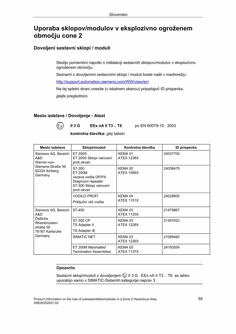
Slovensko
Product Information on the Use of subassemblies/modules in a Zone 2 Hazardous Area 59 A5E00352937-03
Uporaba sklopov/modulov v eksplozivno ogroženem območju cone 2
Dovoljeni sestavni sklopi / moduli
Sledijo pomembni napotki o inštalaciji sestavnih sklopov/modulov v eksplozivno ogroženem območju.
Seznami z dovoljenimi sestavnimi sklopi / moduli boste našli v medmrežju:
http://support.automation.siemens.com/WW/view/en/
Na tej spletni strani vnesite (v iskalnem okencu) pripadajoč ID prispevka,
glejte preglednico.
Mesto izdelave / Dovoljenje - Atest
II 3 G EEx nA II T3 .. T6 po EN 60079-15 : 2003
kontrolna številka: glej tabelo
Mesto izdelave Sklopi/moduli Kontrolna številka ID prispevka
ET 200S ET 200S Sklopi varovani proti okvari
KEMA 01 ATEX 1238X
24037700
S7-300 ET 200M vezava vodila DP/PA Diagnozni repeater S7-300 Sklopi varovani proti okvari
KEMA 02 ATEX 1096X
24038475
Siemens AG, Bereich A&D Werner-von-Siemens-Straße 50 92224 Amberg Germany
VODILO PROFI Priključni vtič vodila
KEMA 04 ATEX 1151X
24028800
S7-400 KEMA 03 ATEX 1125X
21479867
S7-300 CP TS Adapter II TS Adapter IE
KEMA 03 ATEX 1228X
21497622
SIMATIC NET KEMA 03 ATEX 1226X
21089482
Siemens AG, Bereich A&D Östliche Rheinbrücken- straße 50 76187 Karlsruhe Germany
ET 200M Marshalled Termination Assemblies
KEMA 05 ATEX 1137X
24193554
Opozorilo
Sestavni sklopi/moduli z dovoljenjem II 3 G EEx nA II T3 .. T6 se lahko uporabijo samo v SIMATIC-Sistemih kategorije naprav 3 .
Slovensko
Product Information on the Use of subassemblies/modules in a Zone 2 Hazardous Area A5E00352937-03
60
Vzdrževanje
V primeru popravila pošljete sklope/module na kraj izdelave. Popravila lahko izvajajo samo na tem naslovu!
Posebni pogoji za:
KEMA 01 ATEX 1238X
KEMA 02 ATEX 1096X
KEMA 03 ATEX 1125X, ATEX 1226X, ATEX 1228X
1. Sestavni sklopi/moduli se morajo vgraditi v ustrezno ohišje. To ohišje mora zagotoviti najmanj vrsto zaščite IP 54 (po EN 60529). Pri tem je potrebno upoštevati tudi pogoje okolice, v kateri se naprava nahaja. Ohišje mora imeti izjavo (atest) proizvajalca za uporabo v coni 2 (po EN 60079-15).
2. Če na kablu oz. uvodnici tega ohišja v režimu obratovanja temperatura doseže vrednost > 70 °C ali če doseže na razcepih vodnikov v obratovanju temperatura vrednost > 80 °C, se morajo temperaturne lastnosti kablov skladati z dejansko namerjenimi.
3. Uporabljene uvodnice morajo ustrezati predpisani IP zaščiti in poglavju 6.2 (po EN 60079-15).
4. Sprejeti je potrebno ukrepe, da nazivna napetost zaradi tranzientov ne bo prekoračena za več kot 40%.
Posebni pogoji za KEMA 04 ATEX 1151X
1. Priključni vtiči vodila VODILO PROFI morajo biti nameščeni tako, da so zaščiteni pred mehansko nevarnostjo..
2. Če ni mogoče izključiti vdiranje vlage in prahu, je priključne vtiče vodila VODILO PROFI serije 6ES7972-... vgraditi v primerno ohišje. To ohišje mora zagotavljati najmanj vrsto zaščite IP 54 (po EN 60529).
3. Priključni vtiči vodila VODILO PROFI morajo biti pritrjeni s priloženimi vijaki.
4. Priklop oz. ločevanje vodov pod napetostjo ali vklop stikala naprave, npr. zaradi instalacije ali vzdrževanja je dovoljeno, če je zagotovljeno, da območje ni eksplozijsko ogroženo.

Slovensko
Product Information on the Use of subassemblies/modules in a Zone 2 Hazardous Area 61 A5E00352937-03
Posebni pogoji za KEMA 05 ATEX 1137X
1. Sestavni sklopi/moduli se morajo vgraditi v ustrezno ohišje. To ohišje mora zagotoviti najmanj vrsto zaščite IP 54 (po EN 60529). Pri tem je potrebno upoštevati tudi pogoje okolice, v kateri se naprava nahaja. Ohišje mora imeti izjavo (atest) proizvajalca za uporabo v coni 2 (po EN 60079-15).
2. Če na kablu oz. uvodnici tega ohišja v režimu obratovanja temperatura doseže vrednost > 70 °C ali če doseže na razcepih vodnikov v obratovanju temperatura vrednost > 80 °C, se morajo temperaturne lastnosti kablov skladati z dejansko namerjenimi.
3. Sprejeti je potrebno ukrepe, da nazivna napetost zaradi tranzientov ne bo prekoračena za več kot 40%.
Ostale informacije
Ostale informacije o sestavnih sklopih / modulih boste našli v ustreznem priročniku.

Türkçe
62 Product Information on the Use of subassemblies/modules in a Zone 2 Hazardous Area A5E00352937-03
Patlama tehlikesi olan Alan 2 bölgesinde ünite gruplarının/modüllerin kullanılması
İzin verilen Ünite grupları/Modüller Aşağıda, ünite gruplarının/modüllerin patlama tehlikesi olan bölgelerde kurulması için önemli bilgiler bulacaksınız. İzin verilmiş olan ünite gruplarının/modüllerin listesi için internete bakınız: http://support.automation.siemens.com/WW/view/en/ Bu web sitesinde (arama penceresinde) ilgili doküman ID'sini giriniz, bakınız Tablo.
İmalat yeri / Lisans
II 3 G EEx nA II T3 .. T6 EN 60079-15 : 2003 standardına göre
Test numarası: Bakınız tablo
İmalat yeri Ünite grupları/Modüller Kontrol numarası
Doküman-ID
ET 200S ET 200S Hataya karşı emniyetli ünite grupları
KEMA 01 ATEX 1238X
24037700
S7-300 ET 200M Bus kuplajı DP/PA Diyagnoz repeater ünitesi S7-300 Hataya karşı emniyetli ünite grupları
KEMA 02 ATEX 1096X
24038475
Siemens AG, Bereich A&D Werner-von-Siemens-Straße 50 92224 Amberg Germany
PROFIBUS-Bus bağlantı fişi KEMA 04 ATEX 1151X
24028800
S7-400 KEMA 03 ATEX 1125X
21479867
S7-300 CP TS Adaptör II TS Adaptör IE
KEMA 03 ATEX 1228X
21497622
SIMATIC NET KEMA 03 ATEX 1226X
21089482
Siemens AG, Bereich A&D Östliche Rheinbrücken- straße 50 76187 Karlsruhe Germany
ET 200M Marshalled Termination Assemblies
KEMA 05 ATEX 1137X
24193554
Bilgi II 3 G EEx nA II T3 .. T6 lisanslı ünite grupları/modüller sadece 3 numaralı
cihaz kategorisine ait SIMATIC sistemlerinde kullanılabilir.

Türkçe
Product Information on the Use of subassemblies/modules in a Zone 2 Hazardous Area 63 A5E00352937-03
Bakım Bir onarım gerekli olması halinde, ilgili ünite grupları/modüller imalat yerine gönderilmelidir. Onarım sadece orada yapılabilir ve yapılmalıdır.
Özel koşullar:
KEMA 01 ATEX 1238X
KEMA 02 ATEX 1096X
KEMA 03 ATEX 1125X, ATEX 1226X, ATEX 1228X
1.Ünite grupları/modüller uygun bir kasa içine monte edilmelidir. Bu kasa, en az IP 54 (EN 60529 standardına göre) koruma türüne sahip olmalıdır. Burada, cihazın kurulduğu çevre koşulları dikkate alınmalıdır. Kullanılacak kasa için, alan 2 için geçerli bir üretici beyanı mevcut olmalıdır (EN 60079-15 standardına göre).
2.Kabloda ya da bu kasanın kablo girişindeki işletme koşullarında sıcaklık > 70 °C oluyorsa veya işletme koşullarında kablo telleri (damarları) ayrılma noktasında sıcaklık > 80 °C olma ihtimali varsa, kablonun sıcaklık ile ilgili özellikleri, gerçekten ölçülmüş sıcaklıklara uygun olmalıdır.
3.Kullanılmış olan kablo girişleri, talep edilen IP koruma türüne ve bölüm 6.2 (EN 60079-15 standardına göre) dahilindeki taleplere uygun olmalıdır.
4.Nominal gerilimin transiyentlerden (hatlardaki dalgalanmalardan dolayı ani gerilim ve akım değişiklikleri) dolayı azami %40 aşılması için gerekli önlemler alınmalıdır.
KEMA 04 ATEX 1151X için özel koşullar: 1.PROFIBUS Bus bağlantı fişleri, mekanik tehlikeye karşı korunaklı olacak şekilde
monte edilmelidir. 2.İçine toz ve nemin girmesi önlenemediğinde, 6ES7972-... serisi PROFIBUS Bus
bağlantı fişleri uygun bir kasa içine monte edilmelidir. Bu kasa, en az IP 54 (EN 60529 standardına göre) koruma türüne sahip olmalıdır.
3.PROFIBUS Bus bağlantı fişleri birlikte verilen cıvatalarla talimatlara uygun olarak sabitlenmelidir.
4.Montaj veya bakım çalışmaları için elektrik ileten kabloların bağlanması veya sökülmesi ya da cihaz şalterine basılması işlemlerine, yalnızca ilgili sahada patlama tehlikesi bulunmadığı tespit edildiğinde izin verilir.

Türkçe
64 Product Information on the Use of subassemblies/modules in a Zone 2 Hazardous Area A5E00352937-03
KEMA 05 ATEX 1137X için özel koşullar: 1.Ünite grupları/modüller uygun bir kasa içine monte edilmelidir. Bu kasa, en az
IP 54 (EN 60529 standardına göre) koruma türüne sahip olmalıdır. Burada, cihazın kurulduğu çevre koşulları dikkate alınmalıdır. Kullanılacak kasa için, alan 2 için geçerli bir üretici beyanı mevcut olmalıdır (EN 60079-15 standardına göre).
2.Kabloda ya da bu kasanın kablo girişindeki işletme koşullarında sıcaklık > 70 °C oluyorsa veya işletme koşullarında kablo telleri (damarları) ayrılma noktasında sıcaklık > 80 °C olma ihtimali varsa, kablonun sıcaklık ile ilgili özellikleri, gerçekten ölçülmüş sıcaklıklara uygun olmalıdır.
3.Nominal gerilimin transiyentlerden (hatlardaki dalgalanmalardan dolayı ani gerilim ve akım değişiklikleri) dolayı azami %40 aşılması için gerekli önlemler alınmalıdır.
Daha başka bilgiler Ünite grupları/modüller hakkında daha fazla bilgi için ilgili kılavuza bakınız.

Български
Product Information on the Use of subassemblies/modules in a Zone 2 Hazardous Area 65 A5E00352937-03
Използване на електронни блокове/модули във взривоопасната област Зона 2
Допуснати до експлоатация електронни блокове/модули
По-нататък ще намерите важни указания за инсталирането на електронни блокове/модули във взривоопасната област.
Списъкът на допуснатите до експлоатация електронни блокове/модули ще намерите в интернет:
http://support.automation.siemens.com/WW/view/en/
В този уеб сайт въведете (в прозореца за търсене) съответния идентификационен номер, вижте таблицата.
Място на производство / Удостоверение за допускане в експлоатация
II 3 G EEx nA II T3 .. T6 съгласно EN 60079-15 : 2003
Номер на изпитване: вижте таблицата
Място на производство Електронни блокове/модули
Номер на изпитване
Идентификационен номер
ET 200S ET 200S модули, защитени по отношение на възникване на грешки
KEMA 01 ATEX 1238 X
24037700
S7-300 ET 200M шинна връзка DP/PA повторител на диагнозатаS7-300 електронни блокове, защитени по отношение на възникване на грешки
KEMA 02 ATEX 1096 X
24038475
Siemens AG, Bereich A&D Werner-von-Siemens-Straße 50 92224 Amberg Germany
PROFIBUS- съединителен шинен щекер
KEMA 04 ATEX 1151 X
24028800
S7-400 KEMA 03 ATEX 1125X
21479867
S7-300 CP TS адаптер II TS адаптер IE
KEMA 03 ATEX 1228X
21497622
SIMATIC NET KEMA 03 ATEX 1226X
21089482
Siemens AG, Bereich A&D Östliche Rheinbrücken- straße 50 76187 Karlsruhe Germany
ET 200M Модулно разпределени входно-изходни системи
KEMA 05 ATEX 1137 X
24193554

Български
66 Product Information on the Use of subassemblies/modules in a Zone 2 Hazardous Area A5E00352937-03
Указание
Електронни блокове/модули с разрешение за допускане в експлоатация II 3 G EEx nA II T3 .. T6 могат да се използват само в системи SIMATIC с категория на уреда 3.
Поддържане в изправност
За ремонт съответните електронни блокове/модули трябва да се изпратят до мястото на производство. Ремонтът може да се извърши само там.
Особени условия за:
KEMA 01 ATEX 1238X
KEMA 02 ATEX 1096X
KEMA 03 ATEX 1125X, ATEX 1226X, ATEX 1228X
1. Електронните блокове/модулите трябва да се монтират в подходящ корпус. Този корпус трябва да осигурява степен на защита най-малко IP 54 (съгласно EN 60529). При това трябва да се имат предвид условията на околната среда, в които се инсталира устройството. За корпуса трябва да има разяснение на производителя за зона 2 (съгласно EN 60079-15).
2. Когато на кабела или на кабелния вход на този корпус при работни условия се достигне температура > 70 °C, или когато при работни условия температурата на разклонението на жилата може да е > 80 °C, температурните свойства на кабелите трябва да се съгласуват с действително измерените температури.
3. Използваните кабелни входове трябва да съответстват на исканата степен на защита IP и на раздел 6.2 (съгласно EN 60079-15).
4. Трябва да се предприемат мерки номиналното напрежение да не се надхвърля с повече от 40 % чрез преходни процеси.
Особени условия за KEMA 04 ATEX 1151X
1. Съединителните шинни щекери PROFIBUS трябва да се инсталират така, че да са защитени от опасност за механични повреди.
2. Когато не може да се изключи проникването на влага и прах, съединителните шинни щекери PROFIBUS от серия 6ES7972 трябва да се монтират в подходящ корпус. Този корпус трябва да осигурява степен на защита най-малко IP 54 (съгласно EN 60529).
3. Съединителните шинни щекери PROFIBUS трябва да се закрепват с доставените винтове съгласно инструкцията.
4. Свързването или разделянето на токопроводящи жила, или на задействането на превключватели на устройствата, например за инсталационни цели или заради поддръжката, е разрешено, само ако е гарантирано, че областта не е взривоопасна.
Български
Product Information on the Use of subassemblies/modules in a Zone 2 Hazardous Area 67 A5E00352937-03
Особени условия за KEMA 05 ATEX 1137X
1. Електронните блокове/модулите трябва да се монтират в подходящ корпус. Този корпус трябва да осигурява степен на защита най-малко IP 54 (съгласно EN 60529). При това трябва да се имат предвид условията на околната среда, в които се инсталира устройството. За корпуса трябва да има разяснение на производителя за зона 2 (съгласно EN 60079-15).
2. Когато на кабела или на кабелния вход на този корпус при работни условия се достигне температура > 70 °C, или когато при работни условия температурата на разклонението на жилата може да е > 80 °C, температурните свойства на кабелите трябва да се съгласуват с действително измерените температури.
3. Трябва да се предприемат мерки номиналното напрежение да не се надхвърля с повече от 40 % чрез преходни процеси.
Подробна информация
Подробна информация за електронните блокове/модулите ще намерите в съответния справочник.

Română
68 Product Information on the Use of subassemblies/modules in a Zone 2 Hazardous Area A5E00352937-03
Utilizarea unităţilor constructive/modulelor în domeniul cu potenţial exploziv din zona 2
Unităţi constructive/module aprobate
În continuare veţi găsi indicaţii importante pentru instalarea grupelor constructive/modulelor în domeniul cu potenţial exploziv.
Lista cu unităţile constructive/modulele se află pe internet:
http://support.automation.siemens.com/WW/view/en/
Pe această pagină web (în fereastra de căutare) introduceţi ID-ul articolului, vezi tabelul.
Locul de fabricaţie / aprobarea
II 3 G EEx nA II T3 .. T6 conform EN 60079-15 : 2003
Număr verificare: vezi tabelul
Locul de fabricaţie Unităţi constructive/module
Număr verificare
ID articol
ET 200S ET 200S Module de siguranţă
KEMA 01 ATEX 1238 X
24037700
S7-300 ET 200M Cuplaj magistrală DP/PA Repetor diagnoză S7-300 unităţi constructive de siguranţă
KEMA 02 ATEX 1096 X
24038475
Siemens AG, Bereich A&D Werner-von-Siemens-Straße 50 92224 Amberg Germany
Ştecher racord magistrală PROFIBUSr
KEMA 04 ATEX 1151 X
24028800
S7-400 KEMA 03 ATEX 1125X
21479867
S7-300 CP TS adaptor II TS adaptor IE
KEMA 03 ATEX 1228X
21497622
SIMATIC NET KEMA 03 ATEX 1226X
21089482
Siemens AG, Bereich A&D Östliche Rheinbrücken- straße 50 76187 Karlsruhe Germany
ET 200M Marshalled Termination Assemblies
KEMA 05 ATEX 1137 X
24193554
Indicaţie
Unităţile constructive/modulele cu aprobarea II 3 G EEx nA II T3 .. T6 se pot utiliza numai în sisteme SIMATIC din categoria de aparate 3.

Română
Product Information on the Use of subassemblies/modules in a Zone 2 Hazardous Area 69 A5E00352937-03
Mentenanţă
Pentru reparaţie, unităţile constructive/modulele respective se vor trimite la locul de fabricaţie. Reparaţia se poate efectua numai acolo.
Condiţii speciale pentru:
KEMA 01 ATEX 1238X
KEMA 02 ATEX 1096X
KEMA 03 ATEX 1125X, ATEX 1226X, ATEX 1228X
1. Unităţile constructive/modulele se vor monta într-o carcasă adecvată. Această carcasă va garanta cel puţin tipul de protecţie IP 54 (conform EN 60529). La aceasta se vor respecta condiţiile de mediu în care se instalează dispozitivul. Pentru carcasă va fi disponibilă declaraţia producătorului pentru zona 2 (conform EN 60079-15).
2. Dacă la cablu, respectiv la intrarea cablului acestei carcase, în condiţii de funcţionare, este atinsă o temperatură > 70 °C sau dacă în condiţii de funcţionare, la derivaţia conductorilor poate fi o temperatură > 80 °C, caracteristicile de temperatură ale cablurilor trebuie să corespundă temperaturilor reale măsurate.
3. Intrările de cablu utilizate vor corespunde tipului de protecţie IP şi secţiunii 6.2 (conform EN 60079-15).
4. Se vor lua măsuri pentru ca tensiunea nominală prin fenomene tranzitorii să nu depăşească mai mult cu 40 %.
Condiţii speciale pentru KEMA 04 ATEX 1151X
1. Ştecherele de conectare pentru magistrală PROFIBUS se vor instala astfel încât să fie protejate contra pericolelor mecanice.
2. Dacă nu se poate evita pătrunderea umezelii şi a prafului, ştecherele de conectare pentru magistrală PROFIBUS, seria 6ES7972-... se vor monta într-o carcasă adecvată. Această carcasă va garanta cel puţin tipul de protecţie IP 54 (conform EN 60529).
3. Ştecherele de conectare pentru magistrală PROFIBUS se vor fixa corespunzător cu şuruburile livrate.
4. Conectarea, resp. separarea firelor conducătoare de tensiune sau la acţionarea comutatorului aparatului, de exemplu în scopuri de instalare sau întreţinere, este permisă numai dacă se garantează că zona nu prezintă potenţial exploziv.

Română
70 Product Information on the Use of subassemblies/modules in a Zone 2 Hazardous Area A5E00352937-03
Condiţii speciale pentru KEMA 05 ATEX 1137X
1. Unităţile constructive/modulele se vor monta într-o carcasă adecvată. Această carcasă va garanta cel puţin tipul de protecţie IP 54 (conform EN 60529). La aceasta se vor respecta condiţiile de mediu în care se instalează dispozitivul. Pentru carcasă va fi disponibilă declaraţia producătorului pentru zona 2 (conform EN 60079-15).
2. Dacă la cablu, respectiv la intrarea cablului acestei carcase, în condiţii de funcţionare, este atinsă o temperatură > 70 °C sau dacă în condiţii de funcţionare, la derivaţia conductorilor poate fi o temperatură > 80 °C, caracteristicile de temperatură ale cablurilor trebuie să corespundă temperaturilor reale măsurate.
3. Se vor lua măsuri pentru ca tensiunea nominală prin fenomene tranzitorii să nu depăşească mai mult cu 40 %.
Informaţii suplimentare
Informaţii suplimentare cu privire la grupele constructive/module se află în manualul aferent.
Copyright © Siemens AG 2006
Siemens corporation A5E00821386-01
SIMATIC
Product information 07/2006
for the Diagnostic repeater for PROFIBUS-DP manual
This production information contains important information regarding the firmware version 2.0.0 of the diagnostic repeater, order number 6ES7972-0AB01-0XA0. The product information is a constituent part of the supplied product and, in the case of doubt; , the statements made in it have priority over any other statements.
Contents
1 Introduction 2
2 DP cycle time measurement 3
3 Time synchronization by means of S7 system mechanisms 6
4 Support of the I&M function 7
5 Firmware update 10
6 Supplement to the manual 11

Introduction
Product information on diagnostic repeater 2 A5E00821386-01
1 Introduction
In addition to the scope of performance given up until now, the diagnostic repeater, firmware version 2.0.0, modulehardware version 03, also offers the following additional function enhancements:
• DP cycle time measurement,
• Time synchronization by means of S7 system mechanisms and
• Support of the I&M function.

DP cycle time measurement
Product information on diagnostic repeater A5E00821386-01 3
2 DP cycle time measurement
DP cycle time measurement As an alternative to the existing clocked monitoring function (TDX / TDP monitoring, refer to chapter “Monitoring functions for the clocked PROFIBUS bus system“ in the Diagnostic Repeater for PROFIBUS-DP manual), as of firmware version 2.0.0 the diagnostic repeater offers the DP cycle time measurement of the DP system to which the diagnostic repeater is connected.
Note
The functions can only be used alternately. This means that you can use either
• the DP cycle time measurement
or
• the equidistant error function is active.
You cannot operate both functions at the same time.
The following measured values are recorded by the DP cycle time measurement and are made available by the record “DP cycle time”.
• Minimum DP cycle time with time stamp (precision ±0.5 %, resolution 1 µs)
• Maximum DP cycle time with time stamp (precision ±0.5 %, resolution 1 µs)
• Average of the DP cycle time through the entire duration of the measurement (precision ±0.5 %, resolution 50 µs)
• Counter, how many measurements have been carried out
Requirements • Integration of the diagnostic repeater via the GSD file revision 5, software
release 2.0 with the file names si0380a7.gs?. For the GSD file, go to:
http://www.ad.siemens.de/csi/gsd
Entry ID: 113682
• The DP cycle time measurement is only possible in DP-V1 mode.
• The DP cycle time measurement is supported as of modulehardware version 2 of the diagnostic repeater with MLFB 6ES7972-0AB01-0XA0. In modulehardware version 1, a read / write access via SFC 58 / SFC 59 or SFB 52 / SFB 53 to the record 70 will be acknowledged with a negative return value “0x80A9”.
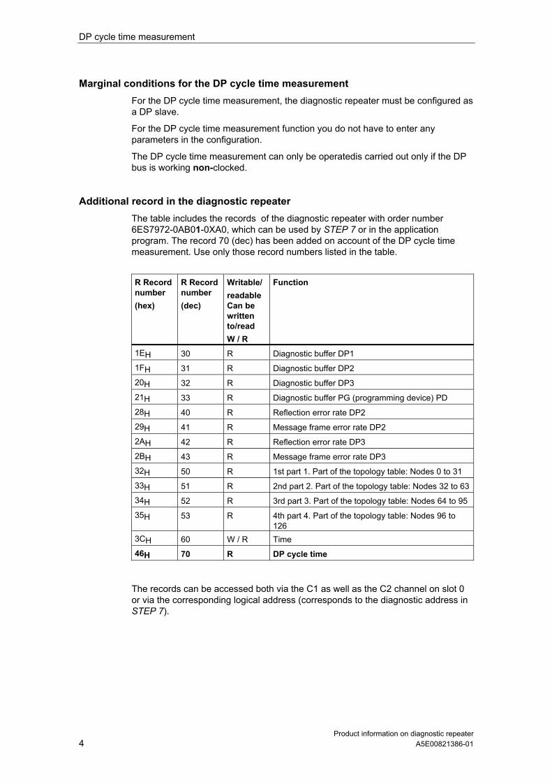
DP cycle time measurement
Product information on diagnostic repeater 4 A5E00821386-01
Marginal conditions for the DP cycle time measurement For the DP cycle time measurement, the diagnostic repeater must be configured as a DP slave.
For the DP cycle time measurement function you do not have to enter any parameters in the configuration.
The DP cycle time measurement can only be operatedis carried out only if the DP bus is working non-clocked.
Additional record in the diagnostic repeater The table includes the records of the diagnostic repeater with order number 6ES7972-0AB01-0XA0, which can be used by STEP 7 or in the application program. The record 70 (dec) has been added on account of the DP cycle time measurement. Use only those record numbers listed in the table.
R Record number (hex)
R Record number (dec)
Writable/ readableCan be written to/read W / R
Function
1EH 30 R Diagnostic buffer DP1
1FH 31 R Diagnostic buffer DP2
20H 32 R Diagnostic buffer DP3
21H 33 R Diagnostic buffer PG (programming device) PD
28H 40 R Reflection error rate DP2
29H 41 R Message frame error rate DP2
2AH 42 R Reflection error rate DP3
2BH 43 R Message frame error rate DP3
32H 50 R 1st part 1. Part of the topology table: Nodes 0 to 31
33H 51 R 2nd part 2. Part of the topology table: Nodes 32 to 63
34H 52 R 3rd part 3. Part of the topology table: Nodes 64 to 95
35H 53 R 4th part 4. Part of the topology table: Nodes 96 to 126
3CH 60 W / R Time
46H 70 R DP cycle time
The records can be accessed both via the C1 as well as the C2 channel on slot 0 or via the corresponding logical address (corresponds to the diagnostic address in STEP 7).

DP cycle time measurement
Product information on diagnostic repeater A5E00821386-01 5
DP cycle time record format Record 70 comprises version number, status byte and the entries for the cycle time measurement; it is made up of a total of 44 bytes. Byte “DP cycle time” record Format
0 Version ( = 01) BYTE 1 DP cycle time measurement status BYTE 2 reserved BYTE 3 reserved BYTE 4…7 Baud rate in kBaud REAL 8…11 Min. DP cycle (in ms) * REAL 12…19 Time stamp BCD 20…23 Max. DP cycle (in ms) * REAL 24…31 Time stamp BCD 32…35 Average DP cycle (in ms) * REAL 36…39 Basic number of measurements + UINT 40…43 Number of measurements carried forward + UINT
* If the clocked monitoring function is active, the configured values will be displayed. + If the clocked monitoring function is active, these values will be set to “0”.
In the case of write access to the record 70, the values will be reset and the measurement restarted.
DP cycle time measurement status byte The entry “DP cycle time measurement status byte” is structured as follows: Byte MSB
7 6 5 4 3 2 1 LSB 0
5 Status_DPCycleTimeMeasurement
The Status_DPCycleTimeMeasurement is structured as follows: Bit Meaning
1 The values are valid Bit 0 0 The values are invalid or frozen 1 Diagnostic repeater is in “Clocked monitoring function” mode Bit 1 0 Diagnostic repeater is in “DP cycle time measurement” mode 1 Clear function inactive (CPU in RUN) Bit 2 0 Clear function active (CPU in STOP)
Bits 3..0.7
0 reserved
The DP cycle time measurement is carried out only in the CPU RUN mode.

Time synchronization by means of S7 system mechanisms
Product information on diagnostic repeater 6 A5E00821386-01
3 Time synchronization by means of S7 system mechanisms
In addition to setting the time using the time reference form from the CPU with record 60, the diagnostic repeater as of firmware version 2.0.0 offers time synchronization by means of S7 system mechanisms.
Requirements • You require a CPU or a CP that supports time synchronization (e.g. all the S7-
400 CPUs do this). Please consult the specifications given in the manual for the module in question.
• Integration of Integrating the diagnostic repeater via the GSD file revision 5 (see above). Time synchronization is only possible in DP-V1 mode.
Marginal conditions for time synchronization by means of S7 system mechanisms
Depending on the scenario, you can synchronize the clock in the diagnostic repeater either via the “Time reference (DS 60)” or by means of time synchronization.
Both processes are “opened” parallel during the start-up of the diagnostic repeater. However, it isn’t practical to run both mechanisms at the same time, and this is acknowledged by a negative message. In such a case, the record 60 is rejected and the time synchronization is carried out via the S7 system mechanisms.
Parameter configuration / activating the time synchronization When configuring parameters for the system in STEP 7 you must enable / activate the time synchronization via the SIMATIC standard mechanism.
Reference You will find more information on time synchronization in general in the Online help for STEP 7.
Support of the I&M function
Product information on diagnostic repeater A5E00821386-01 7
4 Support of the I&M function
In addition to the I&A data (refer to chapter “Identification data” in the Diagnostic Repeater for PROFIBUS-DP manual), as of firmware version 2.0.0 the diagnostic repeater offers support of the I&M function.
The access mechanism to the I&M data has been replaced supplemented in accordance with the PROFIBUS Guideline – order no. 3502, version 1.1 of May 2003.
Definition and features Identification and maintenance data (I&M) is information stored in a module to support you in
• Checking the plant configuration
• Locating hardware modifications in a plant
• Correcting errors in a plant
Identification data (I data) is information regarding the module, like for example, order number and serial number, which are partly also printed on the housing of the module. I data is manufacturer’s information on the module and can only be read.
Maintenance data (M data) is system-dependent information, like for example, installation location and date of location. M data is created during the configuration and written to the module.
I&M data enable modules to be uniquely identified online.
This data is available on the diagnostic repeater as of firmware version 2.0.0.
Note
Only one DP master can access the I&M data of a diagnostic repeater at any one pointtime.

Support of the I&M function
Product information on diagnostic repeater 8 A5E00821386-01
Reading and writing the I&M data with STEP 7 STEP 7 outputs the I&M data to the "Module status – diagnostic repeater" and "Properties - DP Slave" tabs (see the STEP 7 Online Help).
In the HW Config you can enter the modules´ M data (e.g. in a dialog box during the configuration).
The access to the I&M data takes place in accordance with the IEC 61158 -6 standard.
Reading and writing the I&M data without STEP 7 If you wish to use the I&M data without using <i>STEP 7</i>, you must carry out the data access in accordance with the specifications of the PROFIBUS Guideline, Version version 1.1 of May 2003.
In the H system the diagnostic repeater from which the I&M data is to be read must be addressed.

Support of the I&M function
Product information on diagnostic repeater A5E00821386-01 9
Structure of the identification data The following table explains the specific identification data of the diagnostic repeater.
Table: Identification data of the diagnostic diagnosis repeater
I&M data Access Default Explanation Identification data: I&M0 MANUFACTURER_ID read
(2 bytes) 2A hex (= 42 dec) The name of the manufacturer is stored
here (42 dec = Siemens AG). ORDER_ID read
(20 bytes) 6ES7972-0AB01-0XA0 The order number of the module is
stored saved here (= diagnostic repeater).
SERIAL_NUMBER read (16 bytes)
The serial number of the module is stored saved here. This facilitates unique identification of the module.
HARDWARE_ REVISION
read (2 bytes)
The order hardware version of the module is stored here. Is increased when the hardware version product release or the firmware of the module changes.
SOFTWARE_ REVISION
read (4 bytes)
Gives information on the firmware version of the module. If the firmware version number is increased, then the hardware version product release of the module (HARDWARE_REVISION) is also increased.
REVISION_ COUNTER
read (2 bytes)
0000 hex reserved
PROFILE_ID read (2 bytes)
F600 hex Generic Device
PROFILE_SPECIFIC_TYPE
read (2 bytes)
0006 hex (= 6 dec) Internal parameters (in accordance with PROFIBUS DP)
IM_VERSION read (2 bytes)
0101 hex Provides information on the I&M data version (0101 hex = version 1.1).
IM_SUPPORTED read (2 bytes)
000E hex Provides information on available I&M data (I&M1 to I&M3).
Maintenance data 1: I&M1 TAG_FUNCTION read / write
(32 bytes) - Enter a system-wide unique
identification for the module here. TAG_LOCATION read / write
(22 bytes) - Enter the installation location of the
module here. Maintenance data 2: I&M2 INSTALLATION_DATE read / write
(16 bytes) - Enter the installation date for the
module and, if necessary, the relevant time.
RESERVED read / write (38 bytes)
- reserved
Maintenance data 3: I&M3 DESCRIPTOR read / write
(54 bytes) - Enter a comment on the module here.

Firmware update
Product information on diagnostic repeater 10 A5E00821386-01
5 Firmware update
Diagnostic repeater firmware update You can download the function enhancements described - DP cycle time measurement, time synchronization by means of the S7 system mechanisms and support of the I&M function - to diagnostic repeaters as of order number 6ES7972-0AB01-0XA0 via the firmware update via STEP 7 as of V5.2.
To update the firmware, you receive the *.UPD files containing the current firmware.
Requirements
• The diagnostic repeater, the firmware of which must is to be updated, must be must beaccessible online.
• The files with the current firmware version must be available in the file system of your programming device or PC.
Procedure
For information on procedures, refer to the STEP 7 Online Help.
Note
When the firmware is activated the topology table in the diagnostic repeater is deleted (automatically or after you switch the power off / on). After the activation, determine the topology.
Note
If the firmware is automatically activated after downloading, then the diagnostic repeater restarts, the repeater functions are not available during this time. This means the diagnostic repeater and parts of the network are temporarily unavailable.
To obtain the current firmware version go to:
http://www.ad.siemens.de/csi/download
Entry ID: 21186838

Supplement to the Manual
Product information on diagnostic repeater A5E00821386-01 11
6 Supplement to the Manual
Chapter 7.4.3, Statistics buffer Procedure
1. In the topology display, mark the diagnostic repeater, the data for which you want to read.
2. Start the function using the menu item PLC > Statistics.

Product information on diagnostic repeater 12 A5E00821386-01