dic differential interference contrast kim peifley 08/14/15
TRANSCRIPT

DICDifferential Interference Contrast
Kim Peifley08/14/15

DIC – Differential Interference Contrast.
• Allows you to view thin transparent specimens at high resolution and high contrast.
• Only works with glass. It will not work with plastic.• Sample preparation can affect DIC. Mounting
medium. Need difference in Refractive index.

LSM710

1. Get a fluorescent image like you normally do.
Note: Sometimes it is easier to set up DIC with the 10x dry objective first then go to the oil objective.

2. Click Online.3. Click the Aperture.4. Select the proper aperture for the objective. Example: DICIII for the 63x Oil Objective. See next slide for
details.5. In Configuration click DICIII.6. If you need to change the intensity click on the bulb icon and adjust.7. Select Analyzer module D.
In the Zen Software:
2
3
4
5
6
7

Step 4. Select the proper aperture for the objective.
You can find the aperture setting for the objective on the touch pad in two different places :A. On the home screen it will be listed under Objective.B. In the Control tab it will be listed under Objectives.
A B

8. Move the silver lever of the analyzer to the left. See next slide for a close up view.
9. Check the focus through the eyepiece.10. Adjust light if necessary with the light
intensity control dial.11. Close the field diaphragm until you
see the octagon shape. 12. Adjust the condenser using the
condenser focus knob until the octagon is in sharp focus.
13. Using the silver aperture diaphragm knobs on each side to adjust the octagon to center. See following slide for illustration of this.
10
8
11
12
13 13
Steps 11-13 may have to be done in smaller increments and repeated until you can fully see the octagon shape and move it to center. It may also help to do this first with the 10x dry objective then repeat with the 63x oil objective.

Step 8: Analyzer [Silver knob] in left position.
Note: The left or 0º position is for viewing DIC through the eyepiece. It should remain in this position until you are ready to image.

Step 13: Using the silver aperture diaphragm knobs on each side to adjust octagon to center.Here are 3 images showing the movement of the octagon to the center.Note: The image on the right was zoomed out so one could see the edges.

14. Open up field diaphragm .15. In preparation for imaging, set
the analyzer [silver knob] back in right side 75º position.
14
15
Note: The right 75º position is for laser scanning. The knob remains on the left for viewing DIC through the eyepiece.

Back on the software:
16. In Image Setup window select the track you wish to attach DIC to.
17. In Light Path window check the T-PMT box. This attaches DIC to that Track.
18. In the Channels window you will see T-PMT listed.
19. You also now have T-PMT controls.
Note: T-PMT controls off the laser power of the fluorescence track. If you change that when adjusting settings for fluorescence you will have to change your DIC settings.
16
17
19
18
17
18

20. While scanning in Fast XY Adjust your settings for fluorescence and DIC using controls seen in Step 19.
21. You will have to adjust the DIC slider to balance out the illumination. The next slide will show you where to locate the DIC slider.

Adjust DIC slider below the objective
21. You will have to adjust the DIC slider to balance out the illumination. The slider adjustment knob can be found on the microscope beneath the objective. See photo from previous slide for DIC Image.

22. Now take your multi-colored image plus DIC. Below is the final image in split channel view.

23. In order to get the best DIC images you will need to adjust the contrast when post-processing the image. Here just T PMT-T2 was selected to adjust the contrast.

UV510

1. Get a fluorescent image like you normally do.
Note: Sometimes it is easier to set up DIC with the 10x dry objective first then go to the oil objective.

In the Software:2. Click On VIS.3. Click Condenser.4. Select the Condenser Filter. For the 63x
objective it is DICIII.5. Select “None” for Reflector.6. Click Transmitted Light icon.7. Click On.8. Should you need to adjust the light you
can do it from the slider or from the microscope. This location will be shown later.
2
3
4
56
7
8

On Microscope:9. Move the silver lever of the analyzer to the left.10. Put the analyzer slider into the first or far left
position.11. Adjust light if necessary.12. Close the field diaphragm until you can see the
octagon shape.13. Adjust the condenser focus using the condenser
focus knob until the octagon is in sharp focus.14. Using the silver aperture diaphragm knobs on
each side to adjust octagon to center. See following slide for illustration of this.
15. This is the analyzer slider showing the left hand position having the filter.
15
10
9
11
12
14 14
13
Steps 12-14 may have to be done in smaller increments and repeated until you can fully see the octagon shape and move it to center. It may also help to do this first with the 10x dry objective then repeat with the 63x oil objective.

Step 14: Using the silver aperture diaphragm knobs on each side to adjust octagon to center.Here are 3 images showing the movement of the octagon to the center aligning the condenser.

16. In preparation for imaging, return silver lever of the analyzer to the right 75º position.17. Open up the field diaphragm by pulling the lever towards you.18. Push in on the analyzer slider so it is out of the far left or first position.
18
17
16
Note: The right 75º position is for laser scanning. The knob remains on the left for viewing DIC through the eyepiece.

Back on software:19. In Configuration
Control box: Select the track you wish to attach DIC to and check the ChD box.
19
19

20. While scanning Fast XY, adjust your settings for fluorescence and DIC. For DIC settings select ChD in Scan Control box in order to change the Detector Gain settings.
Note: DIC uses the same laser as the fluorescent channel you selected. If you change the laser power for one Channel you must change the gain settings of the other Channel.

21. While scanning in Fast XY you will also need to adjust the DIC slider. This is located under the objective on the microscope turret.
Adjust DIC slider below the objective

22. This is what the image looks like after the gain and DIC slider have been adjusted.

23. Now take your multi-colored image plus DIC. Below is the final image in split channel view.

24. DIC images need to be contrast enhanced in the post processing stage. Here we have only selected the DIC – ChD-T2 channel for contrast adjustment.

LSM780

1. Get a fluorescent image like you normally do.
Note: Sometimes it is easier to set up DIC with the 10x dry objective first then go to the oil objective.

In the Zen Software:
2. Click Transmitted Light On.3. Click the Aperture.4. Select the proper aperture for the
objective. Example: DICIII for the 63x Oil Objective. See following slide for how to determine which filter to select.
5. In Configuration click Bright field.
6. If you need to change the intensity click on the bulb icon and adjust.
7. Select BS-MP-76.
2
3
4
5
6
7

Step 4. Select the proper aperture for the objective.
You can find the aperture setting for the objective on the touch pad in two different places :A. On the home screen it will be listed under Objective.B. In the Control tab it will be listed under Objectives.
A B

Steps 11-13 may have to be done in smaller increments and repeated until you can fully see the octagon shape and move it to center. It may also help to do this first with the 10x dry objective then repeat with the 63x oil objective.
8
On Microscope:8. Move the silver lever of the analyzer to the left.9. Put the analyzer slider into the first or far left position.10. Adjust light if necessary.11. Close the field diaphragm until you can see the octagon
shape.12. Adjust the condenser focus using the condenser focus
knob until the octagon is in sharp focus.13. Using the silver aperture diaphragm knobs on each side
to adjust octagon to center. See following slide for illustration of this.
910
11
12
13 13

Step 13: Using the silver aperture diaphragm knobs on each side to adjust octagon to center.Here are 3 images showing the movement of the octagon to the center aligning the condenser.

Step 9: This is the analyzer slider showing the left hand position having the filter [left] and once again illustrating it’s position on the microscope for DIC [right].

14. In preparation for imaging, return silver lever of the analyzer to the right.15. Open up the field diaphragm.
15
14
Note: The right 75º position is for laser scanning. The lever remains on the left for viewing DIC through the eyepiece.

16. In Channels window select the track you wish to attach DIC to.
17. In Light Path window check the T-PMT box. This attaches DIC to that Track.
18. In the Channels window you will see T-PMT listed.
19. You also now have T-PMT controls.
Back on the software:
Note: T-PMT controls off the laser power of the fluorescence track. If you change that when adjusting settings for fluorescence you will have to change your DIC settings
15
17
17
18
19

20. While scanning in Fast XY Adjust your settings for fluorescence and DIC using controls seen in Step 19.
21. You will have to adjust the DIC slider to balance out the illumination. The next slide will show you where to locate the DIC slider.

Step 21: You will have to adjust the DIC slider to balance out the illumination. The slider adjustment knob can be found on the microscope beneath the objective. See photo from previous slide for DIC Image.
Adjust DIC slider below the objective

22. Now take your multi-colored image plus DIC. Below is the final image in split channel view.

23. In order to get the best DIC images you will need to adjust the contrast when post-processing the image. Here just T PMT-T2 was selected to adjust the contrast.

LCI510

1. Get a fluorescent image like you normally do.
Note: Sometimes it is easier to set up DIC with the 10x dry objective first then go to the oil objective.

In the Software:2. Click On VIS.3. Click Condenser.4. Select the Condenser Filter. For the 63x
objective it is DICIII.5. Select “Analyzer module D” for
Reflector.6. Click Transmitted Light icon.7. Click On.8. Should you need to adjust the light you
can do it from the slider or from the microscope. This location will be shown later.
2
3
4
5
6
7
8
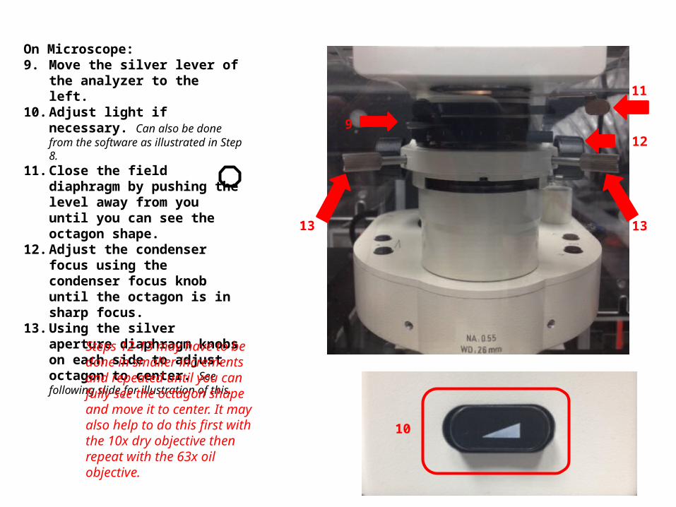
On Microscope:9. Move the silver lever of the
analyzer to the left.10. Adjust light if necessary. Can
also be done from the software as illustrated in Step 8.
11. Close the field diaphragm by pushing the level away from you until you can see the octagon shape.
12. Adjust the condenser focus using the condenser focus knob until the octagon is in sharp focus.
13. Using the silver aperture diaphragm knobs on each side to adjust octagon to center. See following slide for illustration of this.
Steps 12-13 may have to be done in smaller increments and repeated until you can fully see the octagon shape and move it to center. It may also help to do this first with the 10x dry objective then repeat with the 63x oil objective.
9
10
11
12
13 13

Step 13: Using the silver aperture diaphragm knobs on each side to adjust octagon to center.Here are 3 images showing the movement of the octagon to the center aligning the condenser.

14. In preparation for imaging, return silver lever of the analyzer to the right.15. Open up the field diaphragm by pulling the lever towards you.
Note: The right 75º position is for laser scanning. The knob remains on the left for viewing DIC through the eyepiece.
14
15

Back on software:16. In Configuration
Control box: Select the track you wish to attach DIC to and check the ChD box.
16
16

17. While scanning Fast XY, adjust your settings for fluorescence and DIC. For DIC settings select ChD in Scan Control box in order to change the Detector Gain settings.
Note: DIC uses the same laser as the fluorescent channel you selected. If you change the laser power for one Channel you must change the gain settings of the other Channel.

Adjust DIC slider below the objective
18. You will have to adjust the DIC slider to balance out the illumination. The slider adjustment knob can be found on the microscope beneath the objective. See photo on following slide for DIC Image.

19. This is what the image looks like after the gain and DIC slider have been adjusted.

20. Now take your multi-colored image plus DIC. Below is the final image in split channel view.

21. DIC images need to be contrast enhanced in the post processing stage. Here we have only selected the DIC – ChD-T2 for contrast adjustment.