die casting research - unt digital library/67531/metadc... · die casting research annual progress...
TRANSCRIPT

DIE CASTING RESEARCH
Annual Progress Report for Period June 29,1994 - June 30, 1995
Prepared by: Jerry Brevick, Assistant Professor, OSU
Carrol Mobley, Professor, OSU Rajiv Shivpuri, Associate Professor, OSU
Frank Goodwin, ILZRO The Center for Die Casting
228 Baker Systems 1971 Neil Avenue
Columbus, OH 43210 TEL: 614/292-635 1 FAX: 614/292-7852
July 31, 1995
Work Performed under Contract No. DE-FCO7-94ID13233
Prepared for:
U.S. Department of Energy
DISCLAIMER
This report was prepared as an account of work sponsored by an agency of the United States Government. Neither the United States Government nor any agency thereof, nor any of their employees, makes any warranty, express or implied, or assumes any legal liability or responsi- bility for the accuracy, completeness, or usefulness of any information, apparatus, product, or process disclosed, or represents that its use would not infringe privately owned rights. Refer- ence herein to any specific commercial product, process, or service by trade name, trademark, manufacturer, or otherwise does not necessarily constitute or imply its endorsement, recom- mendation, or favoring by the United States Government or any agency thereof. The views and opinions of authors expressed herein do not necessarily state or reflect those of the United States Government or any agency thereof.
DISTRIBUTION OF THIS DOCUMEN IS UNLIMITED < /
MASTER

DISCLAIMER
Portions of this document may be illegible in electronic image products. Images are produced from the best available original document .

Annual Report
on
Evaluation of Chromium Carbide and Other CVD Coatings to Improve the Wear Resistance of
Aluminum and Zinc Die Casting Dies
Submitted to
U.S. Department of Energy Contract #DE-FC07-94ID 13223
Annual Report Number 1 Report Date: July 3 1, 1995
Period Covered: July 1, 1994 - June 30, 1995
Report Prepared by Professor Rajiv Shivpuri
The Ohio State University Center for Die Casting Columbus, OH 43210

,
This 18-month project started on January 15 of 1995. The following objectives were accomplished during the first two quarters of research efforts.
i) .
ii) .
iii) .
iv).
vi).
Vii) .
Continuation of erosion, corrosion and cyclic oxidation testing of OSU chromium carbide coating on H13 pins. The test results will guide our industrial coating partner in selecting their promising coating for the application in H13 die steels.
Project review meeting on March 22 in Cleveland, Ohio. A industrial monitor team, lead by Peter Ried of Doehler-Jarvis was formed. A tentative project plan and schedule was passed in this meeting. A list of potential cooperation industrial partnership was issued. It was decided that Balzers Tool Coating Inc. and a die casting company with multi-cavity die will join the Ohio State University in this research project. This project requires significant contribution for industries in term of coating suppliers and casting campaign.
Meeting with Industrial die casting partner: General Die Casters in Cleveland, Ohio. Several issues were discussed such as identification of multicavity die in the shop floor, the casting alloy 380, the process conditions and the key measurement of wear behavior of die materials and coatings.
Feasibility study of available potential commercial coatings in this project. A plant visit and cooperative discussion with the engineering group of Balzers Tool Coating Inc. was arranged on May 12. Several important coating issues were resolved the die substrate hardness, the type of PVD and CVD coating to be tested, the die maintenance schedule, the frequency of off-line measurement, etc.
A "State of Art" literature review was completed. The review paper "Application of Commercial Coating in Aluminum Die Casting" will be published in the International Conference on Advanced Technologies in Die/Mold Manufacturing to be held on October 10-12 in Columbus, Ohio.
A Survey on Use of Die Coatings in Die Casting Industry was distributed through NADCA local chapters. The compilation of the review will be distributed to our NADCA members for their references. This review will benefit our selection of die coating in this project.
Coating Task Group Report was made during the NADCA Die Materials Committee on Wednesday, June 21, 1995. Prof. Rajiv Shivpuri presented the recent progress on the die materials and coating research at the Ohio State University. Due to the arising difficult to contribute its four cavity die for testing, Ganton Technologies was mentioned for contact as a research partner in this project. A joint meeting with Ganton is under consideration.

Annual Report
o n
Die Cavity Instrumentation OSURF Project 729390
Submitted to
Department of Energy Cont rac t #DE-FC07-94IDl3223
Annual Report Number 1 Report Date: July 26, 1995
Period Covered: July 1, 1994 through June 30, 1995
Report Prepared by Professors C. Mobley and J. Brevick
P. Cheng, V. Venkatasamy, and N. Tsurnagari, Graduate Research Associates
Ohio State University Center for Die Casting Columbus, Ohio 43210

Annual Report Die Cavity Instrumentation Project
OSURF Project 729390 Department of Energy DE-FC07-94 1 D 13223 Report Period: July 1, 1994 - June 30, 1995
Introduction and BackFround
Project Structure and Particiuants
This is the first annual summary report prepared by the OSU Center I-or Die Casting and submitted to the Department of Energy (DOE) for the project entitled "Die Cavity Instrumentation". The mission of this two year duration study is t o evaluate and develop thermal, pressure, and gas flow rate sensors to monitor filling, solidification, and gas entrapment in the die cavity(s) of cold chamber d casting machines and to relate the measurements of those variables to the q u a of the resultant die castings. The successful completion of this project should allow die casting engineers additional and improved sensors with which to
e i t y
monitor and control both the die casting process and the resultant products. The report period covered is the twelve month period from July 1, 1994 through June 30, 1995.
The project is also supported and monitored by The North American Die Casting Association (NADCA), and the Ohio State University Engineering Revarch Center for Net Shape Manufacturing (ERC/NSM). The principal researchers on this project are Professor Carroll Mobley of the Department of Materials Science and Engineering, and Professor Jerry Brevick of the Industrial, Welding, and Systems Engineering Department. Graduate Research Associates Patrick Cheng, Vasanth Venkatasamy, and Nao Tsumagari were funded by and worked on the project.
This project is both assisted and monitored by the North American Die Casting Association (NADCA) Process Technology Task Group, chaired by MI-. Gary Pribyl of Heick Die Casting Corporation. Current membership and company affiliation of the NADCA Process Technology Task Group is given in Appendix A. Dates and places of project review meetings held during this report period are listed in Appendix B.
Technical Background of Pro-iect
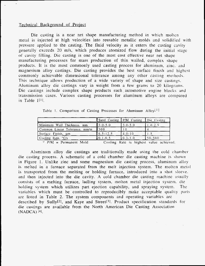
Die casting is a near net shape manufacturing method in which nioltcn metal is injected at high velocities into reusable metallic molds and solidified with pressure applied to the casting. The fluid velocity as it enters the casting cavity generally exceeds 20 m/s, which produces atomized flow during the initial stage of cavity filling. Die casting is one of the most cost effective near net shape manufacturing processes for mass production of thin walled, complex shape products. It is the most commonly used casting process for aluminum, zinc. and magnesium alloy castings. Die casting provides the best surface finish and highcst commonly achievable dimensional tolerance among any other casting mcthocts. This technique allows production of a wide variety of shape and size castings. Aluminum alloy die castings vary in weight from a few grams to 20 kilo, 0 ra 111 s . Die castings include complex shape products such automotive engine blocks and transmission cases. Various casting processes for aluminum alloys are compared in Table 1111.
Table 1 . Comparison of Casting Processes for Aluminum Alloy[ I 1
I Sand Casting P/M Casting Die Casting Minimum Wall Thickness, mm 3 .0 -5 .0 3 . 0 - 5 . 0 I . 0 - 2 . 5 Common Linear Tolerance, mm/m 3 00 10 4 Surface Finish, p m 6 .5 - 12 .5 4 . 0 - i o I .j Cooling Rate, "C/s 0.1-0.5 0.3-1 .0 5 0 - 5 0 0
::: P/M = Permanent Mold Cooling Rate is highest value achieved.
Aluminum alloy die castings are traditionally made using the cold chamber die casting process. A schematic of a cold chamber die casting machine is shown in Figure 1 . Unlike zinc and some magnesium die casting process, aluminuni alloy is melted in a furnace separated from the melt injection system. The molten m e t a l is transported from the melting or holding furnace, introduced into a shot sleeve. and then injected into the die cavity. A cold chamber die casting machine usually consists of a melting furnace, ladling system, molten metal injection system. clic holding system which utilizes part ejection capability, and spraying system. Thc variables which must be controlled to reproducibly make acceptable quality part\ are listed in Table 2. The system components and operating variables are described by Sully[21, and Kaye and Street[3]. Product specification standards f o r die castings are available from the North American Die Casting Association (NADCA) [41.

I - - Elector PImten Stat lonary
Figure 1 . Schematic of die casting machinei5]
Process variables which must be controlled in all die casting campaigns are listed in Table 2. The listed variables are determined prior to a campaign and maintained constant throughout the production period. Cycle times vary from IS seconds for a small part to 2 minutes (120 seconds) for a larger part, such as a transmission housing. Machines are usually operated on a near continuous basis. Kaye and Street(3) and HermanL61 describe the state-of-the-art Cor instrumentation of the cold chamber die casting systems.
Table 2: Casting Variables Melting Furnace
Ladling System Metal Injection System
D i e s
Ejection System
S pray i n g
b r Cold Chamber Die Casting Alloy Composition Melt Temperature Melt Treatment
Shot Sleeve Dimensions Shot Delay Time Shop Profile Cavity Fill Time I nt e n s i f ic at i o n Tie Bar Load Part Con fi g u ra t i on Parting Line Design Runner Design Ingate Location and Size Cooling Line Location Venting Method Vent Location Die Temperature Die Open Time Ejection Timing Ejector Pin Location Spray Type Spraying Timing Spraying Duration Spraying Amount
Press u re

The die casting variables are sometimes determined during part design and final properties are predicted before a die is machined. This is extremely important in die casting because dies are the most expensive component i n the die casting process. Once dies are machined, it is difficult, time consuming. and costly to change them.
A methodology for controlling properties of net shape manufacturing is described in Figure 2. Casting variables are the only variables that can be changed during casting operation. A simple listing of the die casting operating conditions is not sufficient to predict casting properties. Casting properties are directly related to casting microstructures. A few variables are generally adequate to predict the casting microstructures. Those are the solidification conditions, which consist of the temperature gradient at the liquid-solid interface, the solidification rate, the cooling rate, the flow velocity of liquid in the liquid-solid "mushy" zone, and the number or density of nucleation sites in the liquid. These solidification conditions are usually calculated from given casting operational variables using Solidification analysis software. Microstructures predicted using a computer simulation program were in good agreement with actual microstructures in aluminum-silicon alloy sand castings 171. The high fluid flow velocity experienced in the die casting process makes the simulation of die casting solidification conditions difficult. The ability to predict die casting microstructures, even using a computer simulation, is limited today.
A reasonable premise is that die castings made under Controlled and reproducible operational conditions will have reproducible die casting ctructures and properties. Reproducibility of die cast parts is one of the biggest issues in the die casting industry. Despite reasonable control on the operational variables. defective parts are sometimes made. In a previous study of reproducibility o f die cast parts, Naizer measured the volume percent of porosity (% Porosity) i n various types of commercial aluminum alloy die castings made sequentially under stable and controlled die casting conditions [81. Figures 3 and 4 are some of his results for % Porosity for sequentially die cast parts. The % Porosity variation obtained from ten sequentially made die castings in Figure 3 implies that there wax a large shot-to-shot variation during the die casting operation. The supplier of thi \ set had some unknown casting variables which were changing and strongly influencing the formation of porosity. Figure 4 indicates that the supplier o f this particular set of castings had a controlled die casting operation, and the 9% Porosity values were more reproducible. The die casting operational variables which both suppliers used were not given to Naizer, so i t was not known what conditions caused these differences.

Casting Conditions -Superheat -Mold condition I -Casting geometry
Numerical Analysis
f Solidification Conditions
-Migration rate of liquid-solid interface -Temperature gradient at the interface toward
-Local cooling rate -Number of nucleation sites in liquid
liquid
Solid if ic atio n M aps
Solidification Structure Macrostructure
Microstructure
-grain size -grain morphology
-Dendrite arm spacing -Eutectic phase spacing
1
(Mechanical Proper ties > Figure 2. Diagram of property control in casting processed7]

5
2
1
0
0
0
0 0 0
0 0
0 0
- I
I
I - I
I
I
I
I
I
I
I
I
I
I
I
I
I
I
rn I I I I I I I I 1
0
1
0 2 4 6 Shot Number
8 1 0
Figure 3. Archimedes' percent porosity values for sequential, quasi-steady state Group I die castings[8]
5
4 A c1 .?+ m 2 3 2
0
- I
I
I
I
I
I
I
I
I
I
I
I
I . I
I
I 0 0 I
I
I I I I I I I I I i 2 8 0
Average %E' = 0.80 1 sigma = 0.11 I
0 0
0 0 0 0
4 6 Shot Number
10
Figure 4. Archimedes' percent porosity values for sequential, quasi-steady state G r o u p 1 1 I die castings[*]

Most of the process control parameters and variables listed in Table 2 are measured away from the die cavity. Measurement of the thermal and pressure fields in the casting and die near the casting-die interface is expected to provide the most sensitive records of the conditions under which the part is manufactured. This project is focused on evaluating process monitoring sensors which record the thermal, pressure, and gas flow rates in or near the die cavity as a means of securing improved process sensors whose outputs correlate bctter with resultant part quality.
Data for the plunger tip position and hydraulic pressure as a function of time during filling of the shot sleeve, runner(s), and die cavity are commonly measured on state-of-the-art die casting systems. A representative plot of plunger position and hydraulic pressure as functions of time are shown in Figure 5 .
I I ::i:'iirnentahon
0.5 I I I I I I I I I I I
- 20 0.4 Start of second phaie injection B
0.3
0.2 -
-
D Pressure intensification
- - 1 5 t
a. z - 5 Start of injection b W
-10 g PIunger displacement c u
'3 an
C 9
I % m I - m a h
L.
C - 5
Hydraulic injection pressure
- 0 I I '
I I i I 1 I I I I I 1 -
0 0.2 0.4 0.6 0.8 1.0 1.2 1.4 1.6 1.8 20
\ '
Time (s)
Figure 5 . Plunger position and hydraulic pressure history c h a d 3 1
The following variables are commonly obtained from the position and pressure records and used to monitor the die casting process and part quality. Those variables are;
Average fast shot velocity Average slow shot velocity Fast shot position Total shot length Final shot pressure Intensifier rise time Fill time Peak fast shot velocity Travel past impact a n d

How the die casting qualities, defined by such measurables as total porosity. porosity distribution, and surface finish, depend on each of the operational variables is not thoroughly known.
In preparation for the use of the die cavity sensors evaluated as part of this a Shotscope plunger position and velocity recording system was installed project,
on the OSU ERC/NSM Buhler 250h die casting system Buhler die casting system (the Buhler SC) system is to be installed in the OSU ERC/NSM manufacturing laboratory during mid-August, 1995. The Buhler SC machine has an improved shot control system, which will significantly improve the ability to collect plunger position-time data with which to interpret the die cavity filling and solidification phenomena. The temperature and pressure versus time records to be taken from the die cavity sensors evaluated in this project will be synchronized with the plunger position-time record, obtained from the Shotscope recording system, and the cylinder hydraulic pressure-time record taken directly from the Buhler die casting machine.
A improved version of the
Project Tasks The project consists of seven subtasks identified below:
Subtask i :
Subtask 2:
Subtask 3:
Subtask 4:
Subtask 5 :
Subtask 6:
Subtask 7:
Identify and contact commercial suppliers of die casting and related sensors and monitoring systems and obtain descriptions and costs of candidate units.
Procure and install selected sensors identified during Subtask 1 on the OSU ERC/NSM die casting system. Evaluate the sensors through die casting trials.
Correlate sensor data with traditional operating data. Pretlic t and measure gate freezing times and cavity pressure in relation to machine hydraulic pressure record.
Characterize die castings for porosity and contained gas contents and relate to Subtask 3 activities.
Identify several commercial die casting facilities to perform in- plant evaluations of sensors and methodologies developed during first year of project.
Participating die casting facilities install and evaluate cavity sensors during controlled production campaigns.
Characterize porosity and contained gas contents of die castings produced during beta site campaigns and develop correlations between product quality and sensor responses.

Vent
Die Cavity
Cavity Pressure Pin - Ejector Pin -
Literature Survey
Surface Transducer ::: Pressure Probe ::I
The technical literature relating to the cold chamber die casting process was reviewed to identify papers pertaining to temperature, pressure, and gas flow rate sensors. Seventeen references pertaining to sensors and procedures for monitoring the conditions of the die cavity were found and are listed in Appendix C. 14 of the 17 references are contained in NADCA publications.
I )
e Cavity * Thermal Probe *

Survev of Die Cavitv Sensor Usage
To obtain an assessment of the current usage of sensors to measure the thermal and pressure fields and gas flow rates from the die cavity, a survey questionnaire was prepared and submitted to a number of US. die casting companies. The questionnaire of die cavity instrumentation is included a s Appendix D. The questionnaire was sent to NADCA corporate members and also distributed to company representatives attending NADCA Chapter meetings. The completed questionnaires were returned to the Ohio State project investi,; (’ 1tors and the responses were tabulated. 63 completed surveys were returned t o OSU. 60 of the responses were completed by US. die casters companies. 1 survey was completed by a foreign (non-North American) die casting company. 2 surveys were completed by US. die casting equipment manufactures. The responding clic casting companies operate 937 cold chamber machines and 343. hot chamber machines. The total of 1249 die casting machines included by the responding U. S. die casting companies represent 15.6% of the available US. die casting machines. based on the estimated 8000 die casting machines in 1994.
9 1 % of the responding companies indicated that they possess the equipnicnt to monitor the position and velocity of the plunger as a function of time during the filling process. 50% of the responding companies indicated that they have used temperature and pressure measuring sensors near the die cavity as part ot the process monitoring or control practices. Only 15% of the responding companic\ indicated that they use or have available systems to monitor the extend t o which the vents are open or functioning. Only 12% of the responding companies indicated that they use or have available systems for measuring the amount 0 1 ’ gas which is removed from the die cavity during filling. The OSU investigators surmised that the companies indicating that they monitored the amount of gas removed from the die cavity used die cavity vacuum assisted practices.
Based on the results of the die cavity instrumentation survey, the evaluation of sensors to monitor the amount of gas exiting the die cavity to the atmosphere during filling was selected as a priority. The evaluation of the robustness and significance of near cavity temperature sensors and liquid pressure sensors was considered important by the OSU investigators and the members of the NADCA Process Technology Task Group.

Near Die Cavitv Sensors
In the 1988 SDCE publication Die Casting Process. Engineering & Control. H e r n i a n ~ ~ l provides a listing of instrumentation manufacturers, many of whom provide sensors which could be used to monitor the thermal fields in the vicinity of the die cavity and the pressure of the liquid in the die cavity. No manufacturer of sensors to monitor the amount of gas exiting the die cavity through the vents i q
given as part of Herman's instrumentation manufacturers listing.
Near Cavitv TemDerature Sensors
One of the objectives of this study is to experimentally determine ~ h c thermal fields in the die near the casting cavity to (1) monitor the reproducibility of the thermal conditions of the process, (2) determine the heat flux and total heat removed from a region of the die and casting, (3) determine the freezing times of the gate(s) and regions of the casting. The experimental determination of the thermal fields in die can also be used to gauge the adequacy of analytical and/or numerical heat transfer models for the die casting process.
Prior worklg] using a thermal probe consisting of three or more thermocouples in a linear array relative to the die cavity interface has \how11 [liar such a probe allows adequate characterization of the die thermal field near the die cavity to meet the thermal field measurement requirements of this project. A representative temperature versus time record from a multiple thermocouple probe for a 380 aluminum alloy part cast in a H-13 steel die is shown in Figure 7.
The characteristic temperatures used to define the reproducibility 01' a particular die casting practice include:
a. the initial die surface temperature, Tinitial,
a n d
b.- the maximum die surface temperature, Tmax , c. the die surface temperature at the time when the die is opened,
d. the minimum die surface temperature, Tmin, Topen,

Poured a1 660 'C 500
-a -O.o#l n 0" 400
p!
a
Y
3 3 300 8 !z !-
200
100
- 5 0 5 $ 0 15 2 0 SECCMG
25 30 35
Figure 7. Representative Thermal Probe Responsel91
In additional, since the probe contains multiple thermocouples located ;it
known distances from the cavity-die interface, the thermal gradient, dT/dx. at rhc interface can be calculated and used to determine the heat f lux delivered t o the die as a function of time. the reproducibility of the die casting conditions is also judged by:
a. G m a x , the thermal gradient about the die interface at the time when
b. Gmin , the thermal gradient about the die interface at the time
c. Q, the total heat delivered to the die during the process.
Based on the thermal gradient data from the probe,
the die surface temperature reaches its maximum value, Tnl x .
when the die surface reaches its minimum value, Tmin ,
A representative plot of the die surface temperature, heat flux, and total heat delivered to the die during the die closed period of a die casting cycle for 380 aluminum alloy in a H-13 steel die is shown in Figure 8.

Dies Opened \ --,- Lube Sprayed
5 15 25 35 - 5
TIME (sec)
Figure 8. Representative Plot of Die Surface Temperature, Heat Flux and Total Heat Absorbed during a Die Casting Cycle191
The heat flux as a function of time can also provide insight into the reproducibility of the die lubricant spraying practice and the constancy o r change in heat transfer coefficient at the casting-die interface. While extremely long term operating data (for example, measurements of die life) are not a part of this study, it is expected that the variations in Gmax and Gmin should correlate with die life based on thermal fatigue.
As the die casting process is a cyclic process, the process designer and operator attempt to have the process conducted with quasi-steady state thermal conditions. For preferred operating conditions, the die casting system is brought to the thermal quasi-steady state condition (typically requiring 20 to 50 shots to reach the quasi-steady state thermal condition) and all subsequent parts are cast with identical temperature at specified location versus time records. Since cycle time (the time to produce a given part) frequently varies by 10% in a given die casting campaign, absolute quasi-steady state thermal conditions are not generally achieved. Die casting experiments remain to be conducted to define the allowable ranges in each of the thermal characteristics (Tinitial, Tmax, Topen, Tmin, Gmax, Gmin, and Q) for the production of acceptable quality die castings.
The thermocouple probes designed and used in this project consist o f a carrier and an insert made of the same material as the die (H-13 die steel. in this study). The thermocouple probes made in this project are of similar design to

those described in Reference 9. Four type K (chromel-alumel) thermocouples are either capacitor spark discharge welded or silver soldered in holes machined in one of the insert pieces. The tips of the thermocouples are at known locations in the insert, equivalently, at known distances from the die cavity interface. The carrier has the same external dimensions as the pressure probes, to be described in a later section, to allow interchangeability of the thermal and pressure probes in a given die.
The emf versus time data from each of the four thermocouples are recorded Computer software is used to calculate using a computer data acquisition system.
the thermal gradients and heat fluxes and plot the temperatures, thermal gradients and heat flux values following a given die casting cycle.
While thermal probes of the type described are appropriate studies, it remains to be demonstrated that such probes can be uti adequate periods in a manufacturing environment.
for ized
a bor a tory for
Gate Freezing Time
After the cavity is filled, additional pressure is often applied to the metal through the plunger tip. This pressure is called the intensification pressure (See Figure 5). The intensification pressure is generally applied to feed the casting and reduce the porosity in the die castings. The intensification pressure can o n l y effectively feed liquid alloy into the die cavity while the ingate stays liquid. Once the gate is frozen through its thickness, the hydrostatic pressure made by the intensification pressure cannot be transmitted to the casting cavity through the
. remaining liquid. Thus, the effect of the intensification pressure is lost when the gate completes solidification. Therefore, the gate freezing time is an important variable to monitor and control the soundness of die cast parts.
One of the project goals is to investigate how long the gate remains liquid during a die casting operation, and relate the gate freezing time to the timing of the intensification pressure and the final casting quality. The direct temperature measurement by inserting a thermocouple in a gate is not feasible because any thermocouples inserted in a cavity break after the first shot and any thermocouple located within the small cross sectional areas of the gate would affect the initial flow into the cavity. This project attempts to measure the gate freezing time indirectly by using an array of thermocouples (a thermocouple probe) located at or near the gate of the die. By measuring the thermal gradient in the die at the gate, the freezing time of the gate can be calculated.
A commercial finite difference computer solidification analysis software. MAGMAsoft, was used to simulate the gate and part freezing time for a 4 nini thick plate die casting with a 1.5 mm thick wedge gate. An IBM Risc 6000 work
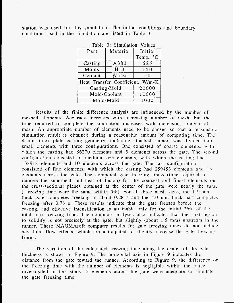
station was used for this simulation. The initial conditions and boundary conditions used in the simulation are listed in Table 3.
Mold-Coolant Mold-Mold
Table 3: Simulation Values
1 0 0 0 0 1 0 0 0
P a r t I Material I Init ial Temn. "C
I Molds I H 1 3 I 1 5 0 I I Coolant I W a t e r I 5 0 I I Heat Transfer Coefficient. W/m2K I
Casting-Mold I 2 0 0 0 0 J
Results of the finite difference analysis are influenced by the number of meshed elements. Accuracy increases with increasing number of mesh, but the time required to complete the simulation increases with increasing number of mesh. An appropriate number of elements need to be chosen so that a reasonable simulation result is obtained during a reasonable amount of computing time. Thc 4 mm thick plate casting geometry, including attached runner, was divided i n t o small elements with three configurations. One consisted of coarse elements. \vi t h which the casting had 86270 elements and 5 elements across the gate. The seconcl configuration consisted of medium size elements, with which the casting had 138918 elements and 10 elements across the gate. The last configuration consisted of fine elements, with which the casting had 259453 elements and 18 elements across the gate. The computed gate freezing times (time required t o remove the superheat and heat of fusion) for the coarsest and finest elements oil
the cross-sectional planes obtained at the center of the gate were nearly the \atnc ( freezing time were the same within 5 % ) . For all three mesh sizes, the 1.5 nini thick gate completes freezing in about 0.28 s and the 4.0 mm thick part coiiipIeIc\ freezing after 0.78 s. These results indicate that the gate freezes before thc casting, and effective intensification is attainable only for the initial 36% 01' the total part freezing time. The computer analyses also indicates that the first region to solidify is not precisely at the gate, but slightly (about 1.5 mm) upstream in thc runner. These MAGMAsoft computer results for gate freezing times do not inc luck any fluid flow effects, which are anticipated to slightly increase the gate I'reezing t imes.
The variation of the calculated freezing time along the center of the gate thickness is shown in Figure 9. The horizontal axis in Figure 9 indicates the distance from the gate toward the runner. According to Figure 9, the diffe'ercncc 0 1 1
the freezing time with the number of elements is negligible within the range investigated in this study. 5 elements across the gate were adequate to simulate the gate freezing time.

- 5 cells across the gate, 0.730 mm from the cover die - - a - - 18 cells across the gate, 0.757 mm from the cover die
0.36 I I I -
- v)
m
.- i! c.
S 0 .- .I-
0 - 0.3 .- 'c a 0 cn
- .- - -
0.28 - -
- -
0.5 1 1.5 2 2.5 3 3.5 0.26* ' ' I " " 1 " ' ' ' ' I 1 ' " ' I 1 1 1 ' 1 1 ' ' " I ' I -
Location from the gate, mm Figure 9. Solidification Time versus Distance from Gate into the Runner
for two mesh sizes.
Cavitv Pressure Probes
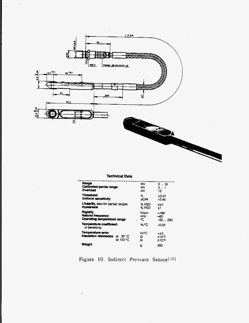
Two types of pressure sensors are commercially available for measuring rhc liquid aluminum alloy pressure while in the die cavity. These two type 01' seti\or\ are ( 1 ) load cells/transducers located behind ejector or pressure pins and ( 2 ) quartz pressure sensors which are placed direct in contact with the alloy i n the die cavity. While a number of companies market load cells/transducers which can be used to monitor the load behind ejector and pressure pins, only one company (Kistler Instrument Corp., Amherst, N.Y.) has been identified which markets pressure sensors which directly contact the alloy in the die cavity. Both types 01' pressure sensors are available from Kistler Instrument Corp. Buhler SC die casting machines are now equipped with direct cavity quartz pressure sensors. Figures 10 and 11 show the basic geometry, dimensions, and technical data 1.01-
both type sensors provided by Kistler Instrument Corp.
47.4 I I
Technical Data Range Callbmted prrtlal range Overload ThrcMhold Uniform wnrHlvlty Lilwrrily, also for partial ranges Hy.tmris Rioidfty Natural trrqumcy Opomting tempmture range Tempemtun cootfkbnt
Temperaturs wror lnsulrtlon mrlrtmce at 20 "C
at 120 % Weight
of sensitivity
kN kN kN N PCM % FSO % FSO Nlpm kHz 'C %I"C
0 ... to 0 ... 1 12 <0.01 -3.45 S f l 51 -160 -60 -50 ... 200 -0.02
N I T e 5
n 210'2
Q 200
n 21013
Figure 10. Indirect Pressure Sensod 101
\

Technical Data
Range ovarlo8d Uniform wnrHtvity (at 250 "C) Umrrity, all ranges Natural froqumcy Accabntlon muitlvity Operating temperature range
Tml#crtum coefficient
Sensor, cable Connector
of sensrtivity
at 20°C at 300 OC
IlUUtrtiOn r#l8bc4
Weigh! (Type 6152AA0.4)
bar bar pC I bar % FSO kHz bar I g
"C "C %I"C
R
g
n
0 ... 2ooo 2500 457 Sk2 -30 <OD7
0 ... m* 0 ... 200* fO.01
1013 10" 280
Figure 1 1. Direct Pressure Sensor[ 1 I 1
The indirect pressure sensor, which records the load transmitted by an ejector or pressure pin has been used in the aluminum die casting industry for a number of years. cavity pressure is translated to the pressure sensor via a sliding pin, friction existing between the sliding pin and die effects the pressure or load recorded by the sensor. Also, the friction typically varies from shot to shot because of inconsistencies between the die and sliding pin due to varying temperaturcs and amount of lubrication applied to the die.
However, problems have been associated with its use. Since the

The direct pressure sensor is a relatively new product for die casting aluminum alloys. Prior to the initiation of this project, it was estimated that four European die casters were using the direct pressure sensor as part of the i r p-rocess monitoring techniques.
The primary objectives associated with usage of the direct pressure sensor is to accurately and repeatedly measure the liquid alloy pressure while in the die cavity and relate that pressure to the hydraulic pressure (and inferred liquid pressure) at the same time. If the gate completes freezing before the intensification pressure is applied, the pressure indicated by the i n cavity direct pressure sensor should be the pressure value at the time of gate freezing, and not the metal pressure corresponding to the intensification pressure. I t is not clear at this time if the increase in gas pressure in the cavity during filling will be measurable using this sensor.
Vent Flow Sensors
The amount of porosity (specifically gas porosity) in a die casting is also influenced by cavity venting. When the air initially present in the die cavity before the metal injection does not escape through the vents during the metal injection, the air is trapped in the casting as gas pores. Monitoring the condition of venting is important to control the total porosity of die castings.
Two types of devices were considered to monitor the condition of vents during a die casting operation. One was a microphone acoustic device and (he other was a hot wire anemometer. The acoustic microphone sensor is primarily intended to monitor whether a vent is open or closed, rather than the instantaneous flow rate of gas exiting the vent. It is anticipated that an iinmediate need exists to implement a vent sensor which could indicate to the die casting operator whether or not the vent was functional (open) during the last shot. The need exits for a sensor which will indicate simply whether the vent is closed. 112 closed, or totally open.
The microphone acoustic pick up device consisted of five op-amps and two condenser microphones as shown in Figure 12. The microphones iiced to date are Radio Shack Replacement Condenser Microphone Element (Cat. No. 270-092B). One microphone was placed directly over a vent, and the other was placed near the first microphone, but off the vent. The op-amp # 3 in Figure 12 subtracts the signals detected by both microphones. This allows only signals generated from the vent to be sensed and eliminates other signals detected during a die casting operation. The op-amp # 5 controls output signals. It sends only signals which have more than a selected voltage to the output. The filtering voltage is controlled by the potentiometer. The output from this circuit was monitored by a Nicolet 4094. digital oscilloscope.

i9v 2Gr- r + if )-w
-9v GGD 18 K
f
-9v
1 OK
@ a- -9v GI40 .
GND 1 OK
GPtD -dp-l ~ OK
0 ut
Figure 12. Circuit Diagram for Microphone Vent Sensors
The characteristics of the microphone acoustic pick-up device were investigated by using various signal sources. Hand claps and air tlows created b y a medical plunger were generated near one of the two microphones, and the output signals were displayed on the oscilloscope screen. A typical signal obtaine from a hand clap is shown in Figure 13. The clap was recorded as a surge, which then gradually disappeared, and the intensity of the signal returned to the baseline. The gradual decay of the intensity was a circuit characteristic.
d

0.02 I " ' ~ I " " I ' " ' I ' " ' ~
0 -
> g -0.02 - m 0 > P
CI - 5 -0.04 - CI z
-0.06 -
-0.08 1 . , . . 1 . . . . 1 . . . . 1 . . . ,
-0.01 0 0.01 0.02 0.03 0.04 Time, s
Figure 13: Acoustic Response to Hand Clap
Air flow through a vent during a die casting operation was simulated by ejecting air from a medical plunger with a 1 mm diameter orifice. A microphone was placed 20 mm above the exit of a 20 cc medical plunger, and 10 and 20 cc 01' ambient temperature air was ejected against the microphone by pushing the plunger by hand. A representative signal created by ejecting 20 cc of air is shown in Figure 14. Intensity gradually increased with respect to time, and reached the maximum value at the moment when the tip of the plunger hit the end wall of the medical plunger. Then the signal gradually returned to the baseline. The gradual decay of the intensity was considered a characteristic of this circuit. The duration of the air flow created by this system was determined at the location where the intensity began to decay. For the particular case shown in Figure 14. the duration of the air flow was about 43 ms. Figure 15 shows the signal obtained during a 10 cc air ejection. The duration of air flow for this case was about 12 in\.
These time responses are anticipated to be similar to those associated with the vent exhaust.
0
-0.5
-1
-1.5
-2
-2.5
-3 0 0.02 0.04 0.06 0.08 0.1
Time, s Figure 14. Representative Acoustic Response to 20 cc Air Flow

> aJ 0) m 0 > 3 P 3
CI - w
CI
0
0
-0.5
-1
-Im5 -2 0 5 0.005 0.01 0.015 0.02 0.025 0.03 0.035 0.04
Time, s Figure 15. Representative Acoustic Response to 10 cc Air Flow
An actual die casting operation involves many sources of acoustic signals. A large amplitude, short duration sound, like a clap, is anticipated at the completion of the filling. It is important to pick up only signals associated with venting to monitor the condition of the vents. However, most signals created by sounds are much weaker than the signals created by the direct flow of air against a microphone. For example, the highest intensity observed from a clap was about 50 mV, whereas the highest intensity observed by exposing a microphone in a n air flow created by ejecting 20 cc air was about 3 V. The signal from a clap would not be detected during the air flow measurement because it is 60 times smallcr than the signal commonly observed by the air flow. Although the second microphone was incorporated to subtract the background noises, it may n o t be necessary during the actual measurement of air flow from vents.
A hot wire anemometer consists of a heated platinum wire and precision resistance measurement equipment[ 121. The electrical resistance of platinum is known to change proportionally with temperature. At an initial stage, the platinum wire in an anemometer is kept under constant temperature by supplying a fixed electric voltage. When this platinum wire is exposed under steady fluid flow, the temperature of the wire changes correspondingly with the rate of the flow. This temperature variation appears in the change on the resistance. The resistance measurement equipment connected to the anemometer converts the resistance drop to the corresponding flow rate.
Several commercial anemometers were investigated for this study. The survey indicated that the response time of the commercially available anemometers was not adequate to measure venting time, which is typically 5 0 t o 100 ms. The microphone acoustic pick-up device was selected for initial iisagc i n this study because the response time of this device is more appropriate.

Part/Die Configuration
The selection or a die casting geometry and associated die is an important factor in evaluating the various sensors. The OSU ERC/NSM provided a die which could be modified and fit with the various sensors under evaluation and allows the die casting of a part which can be easily characterized. The part and associated die are identified as the wall die casting. A schematic illustration ol' the wall die casting is shown in Figure 16. Appropriate features of the wall die casting include:
( I ) the presence of a relatively flat, uniform thickness gate area, which is preferred for the location of opposing temperature probes for a n accurate measurement of the gate freezing time,
measurement of both freezing time and pressure via the usage o f both temperature and pressure sensors.
(3) the convenient location of vents which allow the placement and usage of vent flow sensors.
(4) the presence of walls which allow for assessing the effect of the process parameters on the quality of the casting in the blind (unven ted ) wall areas versus the ventable areas,
determination of porosity distribution and Archimedes' density measu remen t s .
(2) the availability of flat, uniform thickness, regions in the casting for the
( 5 ) the die casting size and shape which allow for easy radiographic
For the initial campaigns, four temperature probes (two on opposing sides of the gate, and two on opposing sides of the floor of the casting) and one pressure probe are to be used at the locations indicated in Figure 17. Venting measurements are initially limited to the establishment of whether ventins occurs or not and the duration of gas exhaust from the die cavity.

“12
Figure 16. Schematic I lustration of the Wall Die Casting
!
Figure 17. Illustration of Wa 1 Die Casting Showing Location o f Sensors

The die cast part selected for use in this project has been successfully cast at OSU as part of a previous study of dimensional variation as a function of die casting operating conditions[l3]. However, none of the near cavity sensors evaluated in this project were employed in that study.
Anticipated Sensor Outputs and Relation to Casting; Oualitv
The output of each sensor is an e.m.f. that is collected using a computer based data acquisition system. The frequency of data collection is rather high as most of the die casting events, such as cavity filling, pressure intensification, and vent exhausting, occur in time frames of tens of milliseconds. Continuously collecting data at this rate throughout the entire casting cycle would generate a large data set which would require relatively large mem-ory storage devices. A time regime has been established far each sensor during which data collection can be triggered and stopped during each casting cycle to limit the collected data t o that essential for the process monitoring and next shot control. For example, i f the total casting cycle is 30 seconds, the temperature sensors about the gate only need to be monitored for the several seconds until the part completes freezing or the 10 seconds during the die is closed . The pressure sensor data collection can be triggered from the plunger when the shot begins and will terminate several seconds later, when the casting cavity is completely filled and begins solidifying. Data from the vent flow sensor will only be collected for about 1 cecond during cavity filling.
Selected sensor response data (thermal probe data in the vicinity of the gates to determine gate freezing time) will require transfer and analysis a t a l~ i te r time (that is, do not allow real time analysis). The aluminum die castings made i n the die casting campaigns in which the sensors are used will be characterized t’or gas content (using the vacuum fusion method) and total porosity (using the Achimedes’ method). Predictions of the total porosity and contained gas content\ will be made based on the sensor outputs prior to measuring the quality value\. Values predicted using sensor data will then be compared to values experimentally determined from castings. Finally, an assessment of the viabi l i ty of using in-cavity sensors to predict the porosity of castings on a shot-to-\hot basis will be made.

Second Year Activities
Project activities during the second year of the project will be consistent with the previously defined project subtasks and project schedule. Work will continue to calibrate and evaluate near cavity sensors for use on the OSU die casting system. Delivery of the Buhler SC die casting machine is expected i n mid- August, 1995. The first die casting campaign with all three types of sensors (thermal probes, direct cavity pressure sensors, and vent flow sensors) LISCCI with the wall casting is scheduled for completion by September 15, 1995. The qual i ty measurements for the die castings made in that campaign should be completed by mid October, 1995.
Simultaneously, one or two aluminum alloy die casting companies will bcgin to use and evaluate the near cavity sensors identified to date on selected dies and parts in their commercial operations. One company has indicated their intention to install several of the near cavity sensors on a commercial part die and begin collecting sensor response data. The sensor data and parts made during process monitored campaigns will be shared with the OSU investigators for inclusion i n this project. The OSU investigators on this project will work with the commercial die casting plant staff in evaluating the adequacy of the sensors and their ab i l i t y to predict part quality.

ADDendix A: NADCA Process TechnoloFv Task Group
Mr. Gary Pribyl, Chairman Heick Die Casting Corp. 6550 W Diversey Ave Chicago, IL 60635 ( 3 1 2 ) - 6 3 7 - 1 1 0 0
Mr. Peter Bauer Doehler-Jarvis Pottstown Pottstown, PA 19464-3760 ( 2 1 5 ) - 3 2 7 - 5 4 8 6
Mr. Les Edwards White Rogers 2895 Harawin Street Batesville, AR 72503 ( 5 0 1 ) - 7 9 3 - 1 8 7 3
Mr. Rich Buchhop BTR Industries Hwy 68 West Russelville, Kentucky 12276 ( 5 0 2 ) - 7 2 6 - 2 4 4 1
Mr. Jeff Murray Anderson Die Casting 1720 South Wolf Road Chicago, IL 60090 ( 7 0 8 ) - 5 4 1 - 3 0 3 0

ApDendix B: Proiect Review Meetings
DATES
8 / 2 5 / 9 4
8 / 2 6 / 9 4
1 1 / 2 9 / 9 4
I 1 / 3 0 / 9 4
1 / 1 0 / 9 5
1 / 1 7 / 9 5 1 / 1 7 / 9 5 1 / 2 2 / 9 5
3/ 1 1 9 5 3 / 7 / 9 5
3/ 1 5 / 9 5 3 / 2 3 / 9 5 6 / 1 4 / 9 5
PLACE ACTIVITIES
NADCA, Rosemont, IL
NADCA, Rosemont, IL
NADCA, Rosemont, IL
NADCA, Rosemont, IL
PNGV, Auburn Hills, MI
Heick Die Casting, Chicago,IL Chicago NADCA Chapter Cleveland, OH
Toledo AFS Chapter NADCA, Rosemont, IL
Chrysler, Auburn Hills, MI Wisconsin NADCA Chapter NADCA, Rosemont, IL
Project Initiation Meeting with Process Technology Task Group Project Review with NADCA R&D Committee Review with Process Technology Task Group Review with NADCA R&D Committee Presentation to Big Three US Auto Manufactures Project review with G. Pribyl Presentation to NADCA Chapter NADCA Die Materials Committee Meeting and Review Presentation to AFS Chapter NADCA R&D Committee Meeting & Project Re view PNGV Meeting Presentation to NADCA Chapter Project Review with Process Technology Task Group & R&D Committees

Appendix C: Technical References
(1) Sensors", Trans. 15th Inter. Die Casting Con. & Ep., 1989, NADCA
(2) Kaye, A. and Street, A., Die Casting Metallurgy, Butterworths, 1982 (3) Phlipot, M. et al, "The Evaluation of Selected Die Casting Process Parameters
Using a Micro-Processor Based Process Monitoring System", Trans. 1 2 th Inter. Die Casting Con. & Ep., 1983, NADCA
(4 ) Booth, S. and Allsop, D., "Thermal Control and Design of Dies", Trans. I I t 1 1 Inter. Die Casting Con. &Ep., 1981, NADCA
( 5 ) Papai, J. and Mobley, C., "Die Thermal Fields and Heat Fluxes During Dic Casting of 380 Aluminum Alloy in H-13 Steel Dies, Trans. 16th Inter. Die Ca\ting Con. & Ep., 1991, NADCA
(6) Hatamura, Y . et al, "Direct Measurement of Metal Pressure and Die Surface Temperature", Trans. 15th Inter. Die Casting Con. & Ep., 1989. NADCA
(7) Yamamoto, Y. et al, "Molten Metal Velocities and Gas Pressure in Die Cavity and Defects in Commercial Aluminum Pressure Die Castings", Trans. 15th Inter. Die Casting Con. & Ep., 1989, NADCA
(8) Cocks, D. and Wall, A., "Technology Transfer in the United Kingdom: Progress and Prospects", NADCA Transactions, 1983, Paper No. G-T83-074
(9) Meyer, H. and Walkington, W., "Process Control in Die Casting", NADCA Transactions, 198 1, Paper No. G-T8 1- 145
(10) Tokui, M. et al., "Development and Application of. Vertical Pressure Die Casting Processtt, NADCA Transactions, 1983, Paper No. G-T83-06 1 .
(1 1) Takach, B., "Some Aspects of Feed Design for Pressure Die Casting Dies", NADCA Transactions, 1979, Paper No. G-T79-094.
(12) Van Huis, P., "The Use of Programmable Controllers in Die Casting", NADCA Transactions, 1981, Paper G-T81-022.
( 13) Mickowski, J., "System for Controlling Critical Parameters", NADCA Transactions, 1981, Paper No. G-T81-141.
(14) Getz, R. and Maze, H., "The Development and Evaluation of Alternative Automation Concepts", NADCA Transactions, 1981, Paper G-T8 1 - 142.
(15) Nishi, N. et al, "The Relationship among Measured Pressure of Molten Metal in Die Cavity, Solidified Structure and Mechanical Properties of Aluminurn Alloy Diecastings", Trans. Japanese Foundryrnen's Society, 1988, pp. 777- 7 8 3 .
( 16) Peterson, A., "Thermocycling Control of Aluminum Die Casting Machincs", Transactions NADCA, 1975, Paper No. G-T75-024.
(17) MTS Report on Commercially Available Sensors for the SSM Process, Submitted by MTS Systems Corporation to Concurrent Technologies Corporation, April 19, 1994.
Mochiku, Y., Hatamura, Y., and Shirahige, K., "Intelligent Die Casting and Seven

NADCA. SUIZVEY ON DIE C A W INSTRUMENTATION

Appendix D (continued) NADCA%URVEY ON DIE C A W INSTRUMENTATON (mthwed)
company-

R e f e r e n c e s
I . Metals Handbook Vol. 2 : Non-Ferrous Alloys, 9th ed., ASM International ( 1 9 8 9 )
2. L.J. Sully: "Die Casting," Metals Handbook 9th ed, Vol 15 Casting, pp. 286-295 ( 1 9 8 8 )
3. Kaye and Street: Die Casting Metallurrrv, Butterworths Monographs i n Materials. Butterworths Publication Co. (1982)
4. NADCA Product Specification Standards for Die Castings, Die Casting Development Council ( 1994)
5. An Introduction to Die Casting, American Die Casting Institute, Des Plaines, 1L ( 1 9 7 7 )
6. Herman, E. A., Die Casting Process. Engineering & Control, Society of Die Casting Engineers, Inc., River Grove, Illinois, (1988).
7. N. Tsumagari, C. Mobley, and P. Gangasani : "Construction and Application o f Solidification Maps for A356 and D357 Aluminum-Silicon Alloy," A F S Transactions, vol. 101, pp. 335-341 (1993)
8. J. Naizer: "Porosity and Contained Gas Measurements as Assessments of Die Casting Quality and Process Control," University (1992)
Master's Thesis, The Ohio State
9. Papai, J., and Mobley, C., "Die Thermal Fields and Heat Fluxes During Die Casting of 380 Aluminum Alloy in H-13 Steel Dies", Transactions 16th International Die Casting Congress and ExDosition, NADCA, pp 377-384, ( 199 1).
10. Kistler Instrument Corp. Product Brochure: Quartz Measuring Tongue for Cavity Pressure (Aluminum), 9225A2, Kistler Instrument Corp, Amherst. N Y 14228-2171, USA, Phone #(716) 691-5100
1 1. Kistler Instrument Corp. Product Brochure: Quartz Cavity Pressure Sensor (Aluminum), 6175A2, Kistler Instrument Corp, Amherst, NY 14228-2 17 I , USA, Phone #(716) 691-5100
12. The Flow and Level Handbook, Vo1.28, Omega Engineering, inc., (1992)
13. Osborne, M., "Analysis of the Effects of Die Casting Process Control on Casting Dimensional Variability", OSU Engineering Research Center for Net Shape Manufacturing Report 94-49-C, ( 1994)

Annual Report
on
Die Soldering Program
Submitted to
U.S. Department of Energy Contract #DE-FC07-94ID 13223
Annual Report Number 1 Report Date: July 3 1, 1995
Period Covered: July 1, 1994 - June 30, 1995
Report Prepared by Frank Goodwin
Center for Die Casting

‘ P
Two principal tasks were undertaken during the reporting period: a literature survey and preparatory die casting campaigns for the structured experiments that will be carried out during the second year of the program.
Regarding the literature survey, two primary sources of information were searched: published information from the open literature and technical information from the files of private organizations. All information was gathered by the end of April and included all information relating to the subject that had been carried out during the last 15 years. Several private organization s were generous in supplying data to the program. An overall survey has been synthesized and is being prepared in the form of a report. An oral report was given at the second meeting of the Industrial Monitoring Team held on May 4,1995.
Four preliminary trials using the research die casting machine were carried out during this year. It was necessary to conduct these trials in order to locate the proper “window” of die casting process variables that will allow die soldering conditions to be reproducibly observed. It proved difficult to obtain a die soldering conditions during the first two trials which relied upon a ramp in front of the ingate within the die cavity where it was expected die soldering would occur. Therefore, a solder pin was placed just in front of this ramp for the third trial and the gate redesigned by narrowing it to half of its original width while doubling its depth. Metal buildup on this solder pin was seen and an SEM analysis of the pin showed an aluminum-rich phase present in the built up area. During the forth trial, the ramp used for the first three trials was replaced by a 90” (vertical) wall. This had 0” draft on the front and back. The solder pin was located directly in front of this wall. Soldered areas were found on both the pin and around the sides of the wall.
During discussion of the results of these trials at the IMT meeting, it became apparent that soldering in zinc die castings in related to growth of a deposition layer. This layer is distinct from a reaction layer because it is very low in iron content. It is apparent that erosion of the die surface is not linked to the phenomenon of soldering in zinc die castings. Thus, soldering in zinc die castings is very distinct from soldering in aluminum die castings where erosion always occurs and therefore soldering in zinc and aluminum die castings should be thought about and treated in very different ways.
Along with metallurgical analyses associated with the four preliminary trials, metallurgical analyses were also carried out on soldered core pins that had been contributed by members of the IMT. Agreeing with the preliminary laboratory trials, metal build up was seen in recessed areas especially areas within the industrial pins that had recessed flutes. A significant Al-Mg deposition layer was seen immediately adjacent to the steel surface. A very thin reaction layer containing iron (e1 micron) is found under this layer, contrasting with the situation in aluminum die castings where the reaction layer is significantly thicker. This was further evidenced that deposition, rather than reaction, is the operative mechanism during soldering of zinc die casting dies.

THE OHIO STATE UNIVERSITY
JERRY BREVICK CARROL MOBLEY
DIE CASTING RESEARCH
Task 2 - Commercial Sensor Evaluation
Review of commercially available sensors is basically complete, however any new sensors that come on the market are also reviewed. The pressure sensors appropriate for this project have been identified, purchased, and received at OSU. Furthermore, the temperature and flow measurement instruments have been designed, constructed, and are being bench tested before mounting in the test die.
Task 3 - Sensor System Integration
During this period, work commenced on integrating the input signals from dl of the sensors on a common time basis. A plan for accomplishing this has been developed and the capabilities of data acquisition systems to collect the data are being evaluated with respect to the requirements of the sensors.
Task 5 - Host Site Testing of Sensors
Recently, contacts were initiated with potential industrial host sites for the testing of sensors. At this time two possible sites are available. Visits to these sites have been scheduled for the next quarter.

3
. THE OHIO STATE UNIVERSITY
RAJIV SHIVPURI
EVALUATION OF CHROMIUM CARBIDE AND OTHER CVD COATINGS TO IMPROVE THE WEAR RESISTANCE OF ALUMINUM
AND ZINC DIE CASTING DIES
Following objectives have been accomplished during last quarter of research effort:
i). Meeting with Industrial die casting partner: General Die Casters in Cleveland, Ohio. Several issues were discussed such as identification of multicavity die in the shop floor, the casting alloy 380, the process conditions and the key measurement of wear behavior of die materials and coatings.
ii). Feasibility study of available potential commercial coatings in this project. A plant visit and cooperative discussion with the engineering group of Balzers Tool Coating Inc. was arranged on May 12. Several important coating issues were resolved: the die substrate hardness, the type of PVD and CVD coating to be tested, the die maintenance schedule, the frequency of off-line measurement, etc.
iii). Establishment of GILD, Group for Increased Lives of Dies was accomplished with the support from industrial companies such as ALCOA, Balzers Tool Coating Inc., Multi-Arc, SAC International, General Die Casters, Ashland Chemicals. Cooperative agreement with each of our industrial team member is being initialized.
iv). Accomplishment of a "State of Art" literature review was accomplished. The review paper "Application of Commercial Coating in A l e u r n Die Casting" will be published in the International Conference on Advanced Technologies in DieMold Manufacturing to be held on October 10-12 in Columbus, Ohio.
v). Completion of A Survey on Use of Die Coatings in Die Casting Industry. The survey was distributed through NADCA local chapters. The compilation of the review will be distributed to our NADCA members for their references. This review will benefit our selection of die coating in this project.

INTERNATIONAL LEAD ZINC RESEARCH ORGANIZATION, INC.
DIE SOLDERING PROGRAM
Work during this quarter of this project focused on defining the die soldering condition so that the primary variables for the designed factorial experiments could be accurately determined. This was done by continuing preliminary trials on the research die casting machine.
It has become apparent that die soldering in zinc die casting is significantly different from that seen with aluminum die casting. Soldering conditions with aluminum are normally seen as areas of direct impingement, whereas this research shows that metal buildup related to die soldering is located on areas where metal flow separation occurs. Approximately 350 shots are sufficient to produce such a buildup.
The experimental results were compared with a set of soldered core pins contributed by a die caster member of the industrial Monitoring Team. Consistent with the differences between aluminum and zinc die casting die soldering, a very thin reaction layer (e1 um) was found under the built up zinc, whereas with aluminum this layer is significantly thicker.