differential power analysis under constrained budget: low
TRANSCRIPT
Differential Power Analysis under Constrained Budget:Low Cost Education of Hackers
Filip Stepanek, Jirı Bucek, Martin NovotnyCzech Technical University in Prague, Faculty of Information Technology
Thakurova 9, 160 00 Prague, Czech RepublicEmail: {filip.stepanek, jiri.bucek, martin.novotny}@fit.cvut.cz
Abstract—The differential power analysis is popular tech-nique in exploiting weaknesses of the embedded systems —mostly of the smart cards. This approach is understandableas the DPA does not require expensive equipment or strongtheoretical background on the device under attack. Thereforeit is ideal for education of beginners or students in the field ofcomputer security.
The aim of this paper is to describe the economy of obtainingthe basic equipment for the education of the differential poweranalysis and to share the experience with its teaching.
Keywords-Differential Power Analysis, education, low costs,cryptanalysis, smart card
I. INTRODUCTION
Cryptography finds its application area in many devices ofeveryday life. For example, smart cards are used for publictransport, hotel keys, payphones, building access, personalidentification, etc. Such large field of applications inducesdangers, like falsification of documents, unauthorized accessto services/buildings, impersonating of someone else’s iden-tity, stealing sensitive information or some other form ofpiracy.
To prevent this unauthorized access to secret informationthe devices like smart cards use some layers of security— for example encryption algorithms like AES, 3-DES,and others. These algorithms, although already proven tobe mathematically unbreakable by common means, can beexploited due to their implementation in form of embeddedsystem [1]. The popular technique of exploiting this weak-ness is called Differential Power Analysis (DPA) and wasfirst published by Kocher et al. in 1998 [2].
There are already ways to defend the embedded systemsagainst the DPA [3]. Such countermeasures include e.g. hid-ing or masking the true power trace [4], thus the processeddata cannot be easily revealed. However, to demonstrate thepower of DPA and the necessity of implementing counter-measures in cryptographic devices, the students must beprovided with their own hands on experience with DPAapplied to devices without countermeasures. In this paper wedescribe our solution practicable under constrained budget.
II. DIFFERENTIAL POWER ANALYSIS
The differential power analysis is a technique that exploitsthe dependency of the processed data on the power consump-
Unit Under Measurement
Oscilloscope PC
Card ReaderInterface HW
BoardSmart Card
Co
mm
un
icat
ion
Communication
Mea
sure
men
t
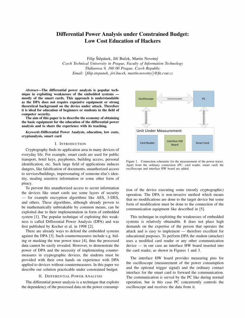
Figure 1. Connection schematic for the measurement of the power traces.Apart from the ordinary connection (PC, card reader, smart card) theoscilloscope and interface HW board are added.
tion of the device executing some (mostly cryptographic)operation. The DPA is non-invasive method which meansthat no modifications are done to the target device but someform of modification must be done to the connection of thecommunication equipment like described in [5].
This technique in exploiting the weaknesses of embeddedsystems is relatively obtainable. It does not place highdemands on the expertise of the person that operates theattack and is easy to implement — therefore excellent foreducational purposes. To perform DPA the student (attacker)uses a modified card reader or any other communicationdevice — in our case an interface HW board inserted intothe card reader, as shown in Figures 1 and 3.
The interface HW board provides measuring pins forthe oscilloscope (measurement of the power consumptionand the optional trigger signal) and the ordinary contactinterface for the smart card to forward the communication.The communication is served by the PC like during normaloperation, but in this case PC concurrently controls theoscilloscope and receives the data from it.
III. PREVIOUS FORM OF EDUCATION
In the last years, students did not perform the mea-surements. They were given the measured data (packageof traces) and they analyzed this data using some sort ofalgebraic system (Matlab or Mathematica). This solutionwas impractical, but was necessary due to time requirements,insufficiency of measuring equipment, and its cost. As wewere equipped with just 2 oscilloscopes, we were not ableto provide sufficient working conditions to every student.Moreover, as the oscilloscopes were for about $25,000 each,we would have to apply extra security arrangements.
This solution seemed to be only possible compromise,however, as a result, the students got no real experiencewith the DPA attack. They were unable to obtain the powertraces themselves and therefore their understanding of thetechnique or background on the DPA/security matter wasinadequate.
IV. LOW COST EDUCATION
In order to improve the students’ understanding of thedifferential power analysis, we needed to acquire new mea-suring equipment that would be available for all studentsin groups of two. In other words, we needed to purchaseat least 10 oscilloscopes and sufficient amount of smartcards, card readers, programmers and measuring adapters.The oscilloscopes are the most cost intensive equipmentand also the most tricky part to select. The following partdescribes the selection criteria.
A. Equipment requirements
The main requirements for oscilloscopes were as follows:• Bandwidth at least 100 MHz — attacking mainly smart
cards clocked at units of MHz,• enough memory depth — at least 1 MSa,• good sensitivity — lowest voltage range better than 10
mV/div with 8 bit sampling,• good connectivity — preferably USB high speed,• fast data transfer — at least 300 kSa/s,• good stability — several hundred measurements must
be attainable without problems with reliability,• responsive user interface, well arranged and simple to
use controls,• two channels — one for measuring power consumption,
one for trigger.The main challenge in selecting the right oscilloscope is
mainly in the data transfer speed. This figure is rarely givenin data sheets (actually, we did not encounter it even once),and therefore we needed to test it on real hardware beforepurchase.
We contacted several test equipment providers for samplesof oscilloscopes that would fit our requirements and meet theprice range up to ca. $2,000. We tested the measurement ona preliminary test setup with a microcontroller performingAES encryption and connected to the PC via serial line.
Although several oscilloscope models fulfill our require-ments according to their specifications, there were substan-tial differences in user interface responsiveness and (moreimportantly) data transfer speed. We tested oscilloscopesfrom Agilent (DSO-X3104A), GW Instek (GDS1152A),Hameg (HMO1024) and Tektronix (MSO2024). We tried toget a sample from Rigol (but did not succeed in time). Wederived our test code from our reference measurement witha Picoscope 5204.
The most important criterion, as already mentioned,proved to be the data transfer speed. With DPA, we neededto perform approx. 500 measurements with 1 MSa eachduring the time frame of a normal laboratory class, thatis 90 minutes. This corresponds to approx. 10 secondsper measurement, not accounting for the time needed formeasurement setup, debugging and analysis. Therefore weset our criterion on data transfer speed at 300 kSa/s or better.This way, with 1 MSa trace, we could transfer at 3.3 sper trace, and have enough time for the rest of the class.Measured data transfer speeds are presented in Table I.
Table IDATA TRANSFER SPEED OF TESTED OSCILLOSCOPES.
Tested model Memory Transfer speed Target model(alphabetical order) [MSa] [kSa/s]
Agilent DSO-X3104A 2 2060 DSO-X3012AGW Instek GDS1152A 2 67 GDS1152A
Hameg HMO1024 2 77 HMO1022Tektronix MSO2024 2.5 312 MSO2012
From our testing, it is clear that of the limited set of oscil-loscope models, only Agilent DSO-X3104A and TektronixMSO2024 could be considered usable for DPA education innormal laboratory class time frame. Agilent DSO-X3104Awas the fastest by a large margin. It should be noted that wetested only the oscilloscopes that we were offered by the testequipment providers with the provision that a model fromthe same family would fulfill our requirements includingour price limit. We cannot rule out that a different model,perhaps from a higher level family, would be better, if asufficient discount from the price would be possible.
B. Design of the measuring equipment
The simplest way of measuring the power consumptionof a smart card is inserting a current-sensing resistor inthe power supply path. The resistor is usually inserted intothe ground path. This way, normal oscilloscope probe canbe used (no differential probe is needed). The measuringfixture must provide the signal from this resistor as well ascommunication signals and auxiliary signals that are used tosimplify triggering. This can be done either as a modificationof a smart card reader, or as a special HW interface boardthat fits between an unmodified reader and the analyzed card.
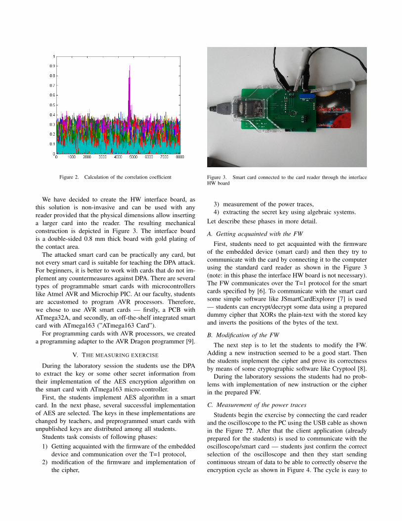
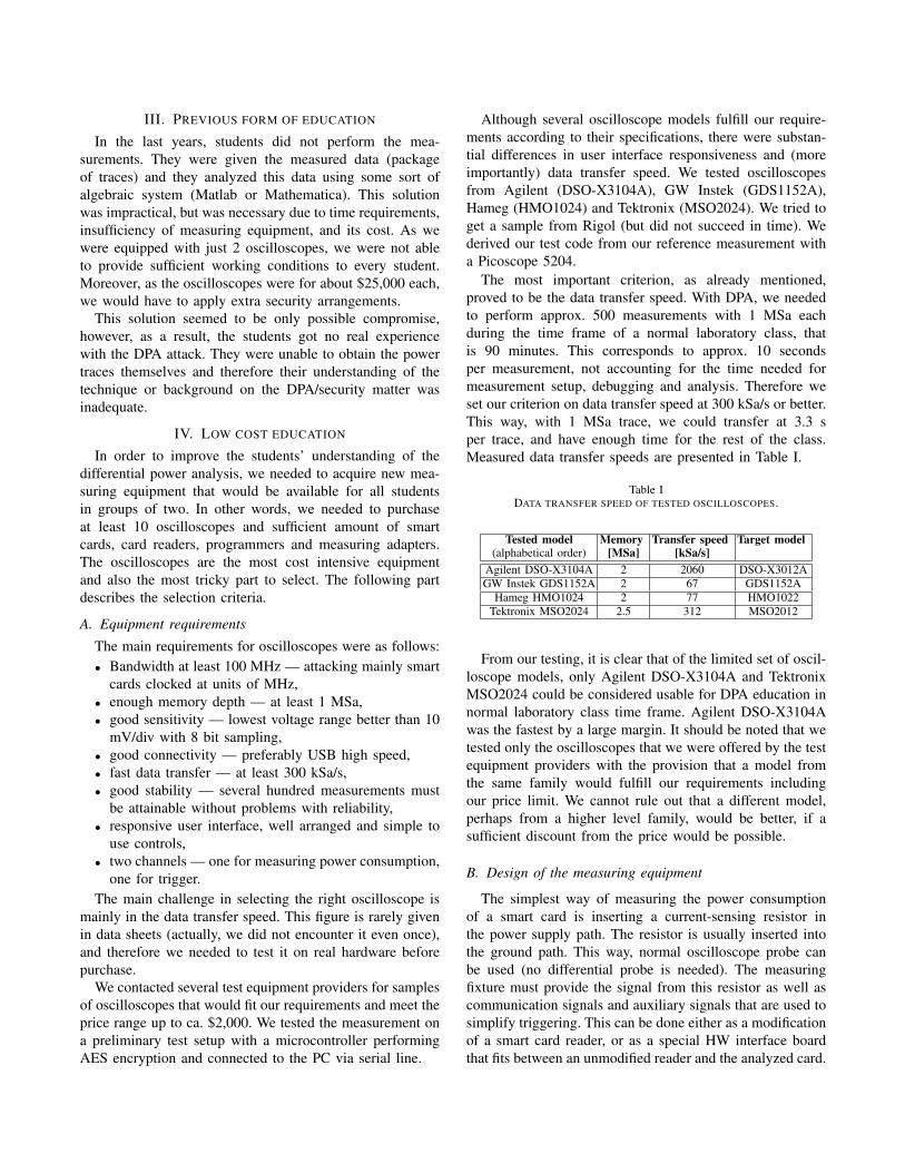
Figure 2. Calculation of the correlation coefficient
We have decided to create the HW interface board, asthis solution is non-invasive and can be used with anyreader provided that the physical dimensions allow insertinga larger card into the reader. The resulting mechanicalconstruction is depicted in Figure 3. The interface boardis a double-sided 0.8 mm thick board with gold plating ofthe contact area.
The attacked smart card can be practically any card, butnot every smart card is suitable for teaching the DPA attack.For beginners, it is better to work with cards that do not im-plement any countermeasures against DPA. There are severaltypes of programmable smart cards with microcontrollerslike Atmel AVR and Microchip PIC. At our faculty, studentsare accustomed to program AVR processors. Therefore,we chose to use AVR smart cards — firstly, a PCB withATmega32A, and secondly, an off-the-shelf integrated smartcard with ATmega163 (”ATmega163 Card”).
For programming cards with AVR processors, we createda programming adapter to the AVR Dragon programmer [9].
V. THE MEASURING EXERCISE
During the laboratory session the students use the DPAto extract the key or some other secret information fromtheir implementation of the AES encryption algorithm onthe smart card with ATmega163 micro-controller.
First, the students implement AES algorithm in a smartcard. In the next phase, several successful implementationof AES are selected. The keys in these implementations arechanged by teachers, and preprogrammed smart cards withunpublished keys are distributed among all students.
Students task consists of following phases:1) Getting acquainted with the firmware of the embedded
device and communication over the T=1 protocol,2) modification of the firmware and implementation of
the cipher,
Figure 3. Smart card connected to the card reader through the interfaceHW board
3) measurement of the power traces,4) extracting the secret key using algebraic systems.
Let describe these phases in more detail.
A. Getting acquainted with the FW
First, students need to get acquainted with the firmwareof the embedded device (smart card) and then they try tocommunicate with the card by connecting it to the computerusing the standard card reader as shown in the Figure 3(note: in this phase the interface HW board is not necessary).The FW communicates over the T=1 protocol for the smartcards specified by [6]. To communicate with the smart cardsome simple software like JSmartCardExplorer [7] is used— students can encrypt/decrypt some data using a prepareddummy cipher that XORs the plain-text with the stored keyand inverts the positions of the bytes of the text.
B. Modification of the FW
The next step is to let the students to modify the FW.Adding a new instruction seemed to be a good start. Thenthe students implement the cipher and prove its correctnessby means of some cryptographic software like Cryptool [8].
During the laboratory sessions the students had no prob-lems with implementation of new instruction or the cipherin the prepared FW.
C. Measurement of the power traces
Students begin the exercise by connecting the card readerand the oscilloscope to the PC using the USB cable as shownin the Figure ??. After that the client application (alreadyprepared for the students) is used to communicate with theoscilloscope/smart card — students just confirm the correctselection of the oscilloscope and then they start sendingcontinuous stream of data to be able to correctly observe theencryption cycle as shown in Figure 4. The cycle is easy to
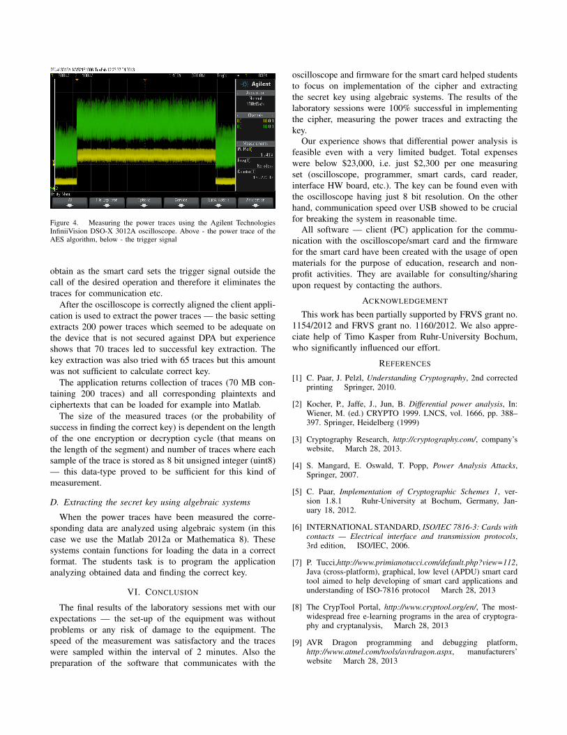
Figure 4. Measuring the power traces using the Agilent TechnologiesInfiniiVision DSO-X 3012A oscilloscope. Above - the power trace of theAES algorithm, below - the trigger signal
obtain as the smart card sets the trigger signal outside thecall of the desired operation and therefore it eliminates thetraces for communication etc.
After the oscilloscope is correctly aligned the client appli-cation is used to extract the power traces — the basic settingextracts 200 power traces which seemed to be adequate onthe device that is not secured against DPA but experienceshows that 70 traces led to successful key extraction. Thekey extraction was also tried with 65 traces but this amountwas not sufficient to calculate correct key.
The application returns collection of traces (70 MB con-taining 200 traces) and all corresponding plaintexts andciphertexts that can be loaded for example into Matlab.
The size of the measured traces (or the probability ofsuccess in finding the correct key) is dependent on the lengthof the one encryption or decryption cycle (that means onthe length of the segment) and number of traces where eachsample of the trace is stored as 8 bit unsigned integer (uint8)— this data-type proved to be sufficient for this kind ofmeasurement.
D. Extracting the secret key using algebraic systems
When the power traces have been measured the corre-sponding data are analyzed using algebraic system (in thiscase we use the Matlab 2012a or Mathematica 8). Thesesystems contain functions for loading the data in a correctformat. The students task is to program the applicationanalyzing obtained data and finding the correct key.
VI. CONCLUSION
The final results of the laboratory sessions met with ourexpectations — the set-up of the equipment was withoutproblems or any risk of damage to the equipment. Thespeed of the measurement was satisfactory and the traceswere sampled within the interval of 2 minutes. Also thepreparation of the software that communicates with the
oscilloscope and firmware for the smart card helped studentsto focus on implementation of the cipher and extractingthe secret key using algebraic systems. The results of thelaboratory sessions were 100% successful in implementingthe cipher, measuring the power traces and extracting thekey.
Our experience shows that differential power analysis isfeasible even with a very limited budget. Total expenseswere below $23,000, i.e. just $2,300 per one measuringset (oscilloscope, programmer, smart cards, card reader,interface HW board, etc.). The key can be found even withthe oscilloscope having just 8 bit resolution. On the otherhand, communication speed over USB showed to be crucialfor breaking the system in reasonable time.
All software — client (PC) application for the commu-nication with the oscilloscope/smart card and the firmwarefor the smart card have been created with the usage of openmaterials for the purpose of education, research and non-profit activities. They are available for consulting/sharingupon request by contacting the authors.
ACKNOWLEDGEMENT
This work has been partially supported by FRVS grant no.1154/2012 and FRVS grant no. 1160/2012. We also appre-ciate help of Timo Kasper from Ruhr-University Bochum,who significantly influenced our effort.
REFERENCES
[1] C. Paar, J. Pelzl, Understanding Cryptography, 2nd correctedprinting Springer, 2010.
[2] Kocher, P., Jaffe, J., Jun, B. Differential power analysis, In:Wiener, M. (ed.) CRYPTO 1999. LNCS, vol. 1666, pp. 388–397. Springer, Heidelberg (1999)
[3] Cryptography Research, http://cryptography.com/, company’swebsite, March 28, 2013.
[4] S. Mangard, E. Oswald, T. Popp, Power Analysis Attacks,Springer, 2007.
[5] C. Paar, Implementation of Cryptographic Schemes 1, ver-sion 1.8.1 Ruhr-University at Bochum, Germany, Jan-uary 18, 2012.
[6] INTERNATIONAL STANDARD, ISO/IEC 7816-3: Cards withcontacts — Electrical interface and transmission protocols,3rd edition, ISO/IEC, 2006.
[7] P. Tucci,http://www.primianotucci.com/default.php?view=112,Java (cross-platform), graphical, low level (APDU) smart cardtool aimed to help developing of smart card applications andunderstanding of ISO-7816 protocol March 28, 2013
[8] The CrypTool Portal, http://www.cryptool.org/en/, The most-widespread free e-learning programs in the area of cryptogra-phy and cryptanalysis, March 28, 2013
[9] AVR Dragon programming and debugging platform,http://www.atmel.com/tools/avrdragon.aspx, manufacturers’website March 28, 2013