diffraction of plane waves by finite-radius spiral phase plates of integer and fractional...
TRANSCRIPT

1TapbatutppSlttptttSsdhmetttt
wgtesp
794 J. Opt. Soc. Am. A/Vol. 26, No. 4 /April 2009 H. Garcia-Gracia and J. C. Gutiérrez-Vega
Diffraction of plane waves by finite-radius spiralphase plates of integer and fractional
topological charge
Hipolito Garcia-Gracia and Julio C. Gutiérrez-Vega*
Photonics and Mathematical Optics Group, Tecnológico de Monterrey, Monterrey, México, 64849*Corresponding author: [email protected]
Received September 30, 2008; revised January 30, 2008; accepted February 4, 2009;posted February 4, 2009 (Doc. ID 102218); published March 17, 2009
A detailed analysis of the plane-wave diffraction by a finite-radius circular spiral phase plate (SPP) with in-teger and fractional topological charge and with variable transmission coefficients inside and outside of theplate edge is presented. We characterize the effect of varying the transmission coefficients and the parametersof the SPP on the propagated field. The vortex structure for integer and fractional phase step of the SPPs withand without phase apodization at the plate edge is also analyzed. The consideration of the interference be-tween the light crossing the SPP and the light that undergoes no phase alteration at the aperture plane revealsnew and interesting phenomena associated to this classical problem. © 2009 Optical Society of America
OCIS codes: 050.1970, 050.4865, 260.1960.
tfntStesesncvslda
2Tpdat
wpfidpfe
. INTRODUCTIONhe old problem of plane-wave diffraction by a circularperture or an obstacle is classic in optics [1,2] and, sur-risingly even nowadays, receives considerable attentiony researchers [3–8]. The development of new approachesnd numerical tools allows one to refine the existing solu-ions or provide alternative ones enriching the physicalnderstanding of this classic problem. On the other hand,he study of screw-dislocated light waves caused by spiralhase plates (SPPs) has gained increasing interest in theast few years [9–14]. Research into light diffraction byPPs is relevant in connection with optical micromanipu-
ation, transfer of orbital angular momentum, and quan-um information studies, among other important applica-ions. Most of the studies have focused on the diffractionroduced by infinite-extent SPPs with integer or frac-ional topological charges with various types of illumina-ion. As far as we know, the problem of finding the diffrac-ion of plane and Gaussian waves by hard-aperturedPPs was first addressed by Kotlyar et al. in [15,16]. As-uming zero light transmission outside of the SPP, theyerived analytical expressions for the Fresnel and Fraun-ofer diffraction patterns in terms of series of hypergeo-etric functions. In a more realistic situation, where the
xtent of the incident wave can be several times largerhan the finite diameter of the SPP, the consideration ofhe interference between the light crossing the SPP andhe light that undergoes no phase alteration at the aper-ure plane can be of crucial importance.
In this paper we study the general problem of plane-ave diffraction by a finite-radius circular SPP with inte-er and fractional topological charge and with variableransmission coefficients inside and outside of the platedge. We characterize the effect of varying the transmis-ion coefficients and the parameters of the SPP on theropagated field. Particular emphasis is made on the vor-
1084-7529/09/040794-10/$15.00 © 2
ex structure and the total vortex strength of the dif-racted wavefronts during the continuous transition from
to n+1 topological charge of the SPP. We corroboratedhat the interference between the light diffracted by thePP and the light that undergoes no phase alteration athe aperture plane not only modifies the symmetry prop-rties of the diffracted pattern, but also its optical vortextructure. The effects of a phase apodization at the SPPdge on the field distribution and its vortex structure aretudied in detail as well. The appropriate form of Babi-et’s principle for the problem is presented and numeri-ally confirmed. This work extends and consolidates pre-ious studies on the diffraction of SPPs, and generalizeseveral known special cases, for example, the hard circu-ar aperture and obstacle [1,2,4,5], the uniform-phaseisk, and the infinite and finite-radius SPP [12,15,16],mong others.
. STATEMENT OF THE PROBLEMhe general problem is formulated as follows: a linearlyolarized plane wave with wave number k, time depen-ence exp�−i�t� illuminates a circular SPP with radius and topological charge � (Fig. 1). The wave field at the ini-ial plane (r0, �0, z=0+) is
U�r0,�0� = �A1 exp�i��0 + i�� r0 � a
A2 r0 � a� , �1�
here the transmission coefficients A1 and A2 are com-lex in the most general situation (0� �A1�, �A2��1), � de-nes the phase singularity of strength 2��, and � intro-uces an optional uniform phase shift on the light thatasses through the SPP. The possibility of adjusting theour parameters �A1 ,A2 ,� ,�� allows one to model a vari-ty of special cases, including, for example, a transparent
009 Optical Society of America

afi=�tk
AIUw
wotE
wfsfE
BIt
Ftf
wgig
wTopttof
iniwaitsl
3PLSErg
wdn
w
H. Garcia-Gracia and J. C. Gutiérrez-Vega Vol. 26, No. 4 /April 2009 /J. Opt. Soc. Am. A 795
perture (A1=1, A2=0, �=0, �=0), a hard-aperturednite-radius SPP of integer order (A1=1, A2=0, �=n, �0), or a transparent uniform-phase plate (A1=1, A2=0,=0, �). Throughout this paper we assume that the aper-
ure diameter is much larger than the wavelength (i.e.,a�1).
. Fresnel Diffractionn the paraxial approximation, the complex amplitude�r� at the observation point r= �r ,� ,z� can be obtainedith the Huygens–Fresnel integral [17],
U�r� = −ik
2�zexp�i
kr2
2z ��0
r0dr0�0
2�
d�0U�r0,�0�
exp�ik
2zr0
2 − 2rr0 cos��0 − ��� , �2�
here U�r0 ,�0� is the aperture function of the diffractingbject located at the z=0 plane. When the aperture func-ion contains either amplitude or phase discontinuities,q. (2) is only valid for distances
z � L = 2a�ka/��1/3, �3�
here a is the distance from the propagation axis to thearthest discontinuity [17]. In Sections 3 and 4 we willolve the Huygens–Fresnel integral for several meaning-ul and unexplored cases of the general transmittanceq. (1).
. Fraunhofer Diffractionn the region of Fraunhofer diffraction (i.e., the far field),he Huygens–Fresnel integral Eq. (2) simplifies to
Ufar field�r� =k
i2�zexp�i
kr2
2z ��0
r0dr0�0
2�
d�0U�r0,�0�
exp�− ikrr0
zcos��0 − ��� . �4�
or the initial field Eq. (1), the Fraunhofer diffraction in-egral Eq. (4) can be analytically evaluated yielding theollowing result:
Fig. 1. (Color online) Geometry of the SPP aperture function.
Ufar field�r� =ka2
izexp�i
kr2
2z ��A1
�− i�n exp�in��
�n + 2���n + 1��
2�n
1F2�1 +n
2,2 +
n
2,1 + n;−
2
4 �+ A2��� � −
J1� �
�� , �5�
here kar /z is the normalized radius, ��x� is theamma function, J1�x� is the first-order Bessel function, �s the Dirac delta function, and 1F2�� ,� ,� ;x� is the hyper-eometric function
1F2��,�,�;x� = �m=0
���m
���m���mm!xm, �6�
ith ���m ���+m� /���� being the Pochhammer symbol.he first summand of Eq. (5) represents the contributionf the light crossing through the SPP and has been re-orted previously in some works, e.g., Eq. (3) in [15]. Onhe other hand, the second summand of Eq. (5) representshe contribution of the light crossing the aperture planeutside of the SPP, and actually corresponds to the dif-raction of a plane wave by a circular opaque obstruction.
Two observations are in order: first, Eq. (1) assumes thenfinite extent of the incident plane wave. It should beoted that such an assumption is not always realistic, be-
ng conventionally used in analytical calculations,hereas upon numerical simulation the use of a limitingperture is inevitable. Additionally, Eq. (1) assumes andeal aperture such that the wave field is discontinuous athe boundary r0=a in the most general situation. The con-equences of these two assumptions will be discussedater in Section 3.
. FINITE-RADIUS INTEGER-STEP SPIRALHASE PLATEet us first consider the case when the phase step of thePP is integer, i.e., �=n. By substituting the initial fieldq. (1) into the Huygens–Fresnel integral Eq. (2), sepa-ating the radial integral, and solving the angular inte-ral with the help of the known result
�0
2�
d�0 exp�− ikr
zr0 cos��0 − �� + in�0�
= in2� exp�in��Jn�−kr
zr0� , �7�
here Jn is an nth-order Bessel function, we obtain theiffraction pattern of a finite-radius integer-step SPP,amely
Un�r,�;z� = −ika2
zexp�i
kr2
2z � A1�− i�n exp�in� + i��Gn�r,z�
− A2G0�r,z� + A2, �8�
here

a
tIrf
Efbtd
mabttpm[fma
AAt(lpio=p
apddc=wptgmfws
iaa
c
FpAwz
Ft=s(c(
796 J. Opt. Soc. Am. A/Vol. 26, No. 4 /April 2009 H. Garcia-Gracia and J. C. Gutiérrez-Vega
Gn�r,z� =�0
1
w exp�ika2
2zw2�Jn�kar
zw�dw, �9�
nd G0�r ,z� in Eq. (8) is a special case of Eq. (9) for n=0.For arbitrary values of its parameters, it appears that
he integral in Eq. (9) cannot be evaluated in closed form.n view of this, Kotlyar et al. [15] derived the following se-ies expression for Gn�r ,z� in terms of hypergeometricunctions:
Gn�r,z� =1
n!� ikar
2z �n
�m=0
1
�2m + n + 2�m!
� ika2
2z �m
1F2�2 + 2m + n
2,4 + 2m + n
2,1 + n;
− �kar
2z �2� . �10�
ven though Eq. (10) is an exact series solution of Eq. (9),rom a numerical point of view its evaluation can be cum-ersome, especially for small propagation distances (ofhe order of L) for which the factor �ka2 /2z�m increasesramatically.The application of the standard numerical integrationethods, e.g., Gaussian–Legendre quadrature, to evalu-
te Eq. (9) is also not practical because the integrand cane highly oscillatory depending of the magnitude of theerm k /z inside both the exponential and the argument ofhe Bessel function. To save this crucial point, in this pa-er we will employ the partitioned Gaussian quadratureethod (PGQM) introduced originally by Haider and Liu
18] to numerically calculate Fourier and Bessel trans-orms of highly oscillatory functions, and that, in our nu-erical tests, resulted to be the more accurate and reli-
ble method to evaluate Gn�r ,z� and G0�r ,z�.
. Uniform-Phase Disk (n=0, �Å0)disk of radius a with uniform phase shift � and variable
ransmission coefficients can be easily modeled with Eqs.1) and (8) by setting n=0 and ��0. Depending on the se-ected values of A1, A2, and �, we can model differenthysical setups, such as a circular aperture (A1=1, �=0)n a completely opaque plane A2=0, or an opaque circularbstacle (A1=0, A2=1, �=0), or a transparent plane A21 and a transparent circular disk A1=1 with arbitraryhase shift �.Figure 2 shows the radial distribution of the intensity
nd phase of the diffracted plane waves by three differenthysical versions of the disk with phase shift �=� /5: aisk with unitary transmission coefficients A1=A2=1, aisk with A1=0.8 and A2=0.4, and a disk with inter-hanged transmission coefficients, i.e., A1=0.4 and A20.8. All diffraction patterns throughout this documenthere calculated using plane waves of �=632.8 nm andhase objects of radius a=500 �m. We can see from Fig. 2hat when the inner transmission coefficient A1 has a big-er value than the outer transmission coefficient A2, theain characteristic in the intensity distribution is a dif-
erence in the constant levels of its oscillatory behavior,hereas the phase distribution presents a phase-jump
tructure located exactly at the position of the discontinu-
ty r /a=1. Both the magnitude of the phase jump and themplitude of the oscillations in the r /a�1 region increases A2→0 [Fig. 3(a)].On the other hand, when the inner transmission coeffi-
ient A1 is smaller than the outer transmission coefficient
ig. 2. (Color online) (a) Intensity and (b) phase of diffractedlane waves by uniform-phase disks of �=� /5 with A1=1 and2=1 (solid curve), with A1=0.8 and A2=0.4 (dashed curve), andith A1=0.4 and A2=0.8 (dashed-dotted curve), observed at/L=2.
ig. 3. (Color online) Radial phase distributions of the diffrac-ion patterns at z /L=2 caused by disks with (a) phase shift �� /6, inner transmission coefficient A1=1, and outer transmis-ion coefficients A2=0.2 (solid curve), 0.5 (dashed curve), and 0.8dashed-dotted curve); (b) phase shift �=� /3, outer transmissionoefficient A2=0.9, and inner transmission coefficients A1=0.2solid curve), 0.5 (dashed curve), and 0.8 (dashed-dotted curve).
AdtA
BTfwutuaU�
mitfa
4tp
CTi(t
pdbtSHpphsaiabwaSat
vbmocadgiw
Fpc
Fdo
H. Garcia-Gracia and J. C. Gutiérrez-Vega Vol. 26, No. 4 /April 2009 /J. Opt. Soc. Am. A 797
2 there is no significant perturbation in the radial phaseistribution at r /a=1, but the amplitude of the oscilla-ions in the shadow of the disk, i.e., r /a�1 increases as1→0. This behavior can be seen in Fig. 3(b).
. Babinet’s Principlehe fact that the transmission coefficients were left as
ree parameters allowed us to confirm Babinet’s principle,hich, in our case, takes a different form than the onesually found in textbooks [1]. Let UA1,A2
be the diffrac-ion pattern due to a plane wave passing through aniform-phase disk with transmission coefficients A1, A2,nd phase shift �. For complementary screens UA1,A2
and1−A1,1−A2
, and real-valued transmission coefficients 0A1, A2�1, Babinet’s principle can be rewritten as
UA1,A2+ U1−A1,1−A2
= U1,1. �11�
Equation (11) also holds when the values of the trans-ission coefficients themselves are complementary, that
s A1+A2=1. However, if instead of complementing eachransmission coefficient we invert them, the expressionor the alternate form of Babinet’s principle changes, too,nd is given by
UA1,A2+ UA2,A1
= �A1 + A2�U1,1. �12�
The numerical confirmation of Eq. (12) is shown in Fig., where we see that there is very good agreement be-ween �A1+A2�U1,1 and UA1,A2
+UA2,A1radial diffraction
atterns, both for the intensity and phase distributions.
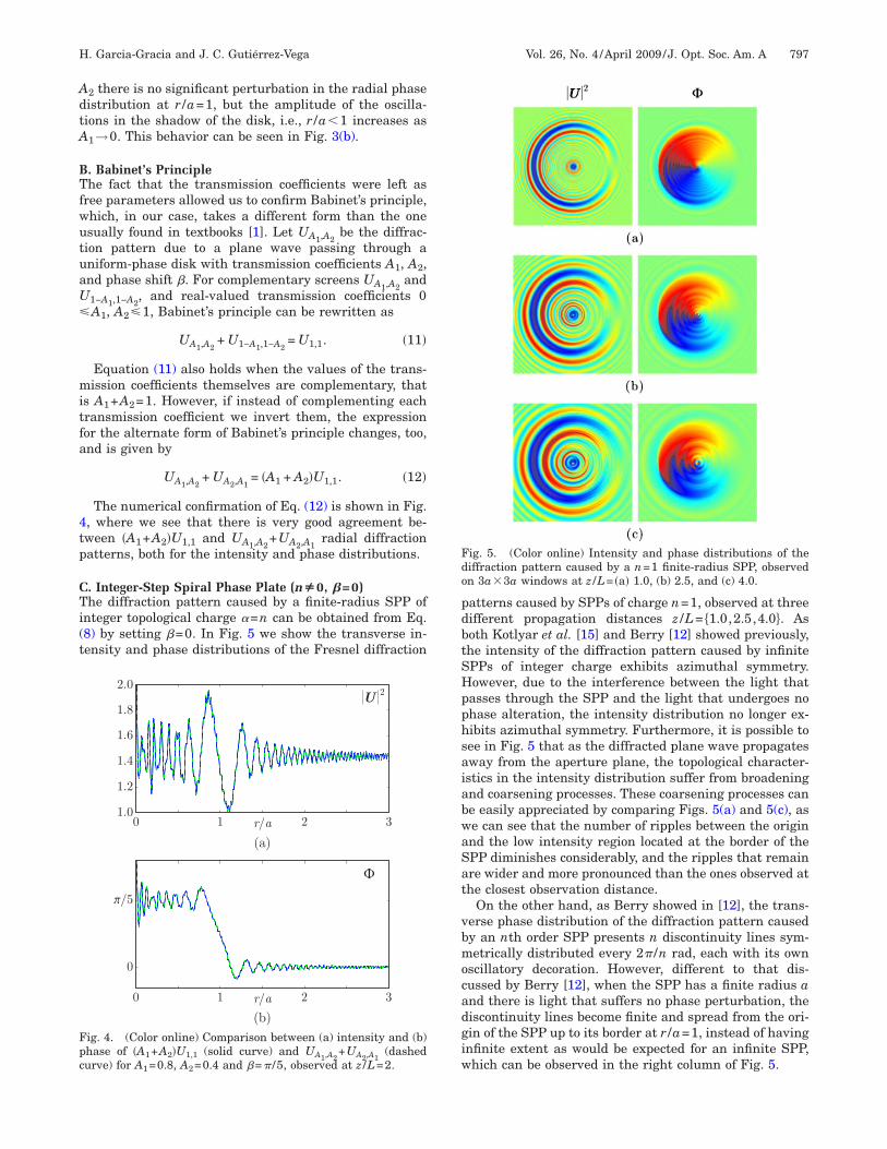
. Integer-Step Spiral Phase Plate (nÅ0, �=0)he diffraction pattern caused by a finite-radius SPP of
nteger topological charge �=n can be obtained from Eq.8) by setting �=0. In Fig. 5 we show the transverse in-ensity and phase distributions of the Fresnel diffraction
ig. 4. (Color online) Comparison between (a) intensity and (b)hase of �A1+A2�U1,1 (solid curve) and UA1,A2
+UA2,A1(dashed
urve) for A =0.8, A =0.4 and �=� /5, observed at z /L=2.
1 2atterns caused by SPPs of charge n=1, observed at threeifferent propagation distances z /L= �1.0,2.5,4.0�. Asoth Kotlyar et al. [15] and Berry [12] showed previously,he intensity of the diffraction pattern caused by infinitePPs of integer charge exhibits azimuthal symmetry.owever, due to the interference between the light thatasses through the SPP and the light that undergoes nohase alteration, the intensity distribution no longer ex-ibits azimuthal symmetry. Furthermore, it is possible toee in Fig. 5 that as the diffracted plane wave propagatesway from the aperture plane, the topological character-stics in the intensity distribution suffer from broadeningnd coarsening processes. These coarsening processes cane easily appreciated by comparing Figs. 5(a) and 5(c), ase can see that the number of ripples between the originnd the low intensity region located at the border of thePP diminishes considerably, and the ripples that remainre wider and more pronounced than the ones observed athe closest observation distance.
On the other hand, as Berry showed in [12], the trans-erse phase distribution of the diffraction pattern causedy an nth order SPP presents n discontinuity lines sym-etrically distributed every 2� /n rad, each with its own
scillatory decoration. However, different to that dis-ussed by Berry [12], when the SPP has a finite radius and there is light that suffers no phase perturbation, theiscontinuity lines become finite and spread from the ori-in of the SPP up to its border at r /a=1, instead of havingnfinite extent as would be expected for an infinite SPP,hich can be observed in the right column of Fig. 5.
ig. 5. (Color online) Intensity and phase distributions of theiffraction pattern caused by a n=1 finite-radius SPP, observedn 3a3a windows at z /L= �a� 1.0, (b) 2.5, and (c) 4.0.

tiststFTtpm
sns�ta
DPTt
wCpp
Etcbrbitsblbvttatm
lnfiaettaups
wtttpm=scpp
Fda(
798 J. Opt. Soc. Am. A/Vol. 26, No. 4 /April 2009 H. Garcia-Gracia and J. C. Gutiérrez-Vega
In [15] Kotlyar et al. presented the intensity distribu-ion of the diffraction pattern caused by a SPP with n=3lluminated by a finite-radius plane wave. The physicaletup used by Kotlyar et al. [15] can be modeled by settinghe transmission coefficients to A1=1 and A2=0, which ishown in Fig. 6(a). However, Eq. (1) allows us to changehe transmission coefficients and Eq. (8) provides theresnel diffraction pattern for any values of A1 and A2.aking advantage of this, in Fig. 6 we can see how the in-ensity and phase distributions of the Fresnel diffractionattern change as A2 goes from 0 to 1; note the loss of azi-uthal symmetry in the intensity distribution and the
ig. 6. (Color online) Intensity and phase distributions of theiffraction pattern caused by a n=3 finite-radius SPP, observedt z /L=1.0 for A1=1 and A2= �a� 0, (b) 0.25, (c) 0.5, (d) 0.75, ande) 1.
piral behavior of the discontinuity lines in the illumi-ated region r�a of the phase distribution. It is also pos-ible to observe in the left column of Fig. 6 that once A20, there no longer exists a n=3 vortex on the propaga-
ion axis, since as A2→1 a nonzero intensity spot appearst the origin.
. Optical Vortex Structure of the Integer-Step Spiralhase Platehe vortex strength Sn of a light distribution inside theransverse circuit C is determined with the line integral
Sn =1
2��
C
d����r�
��, �13�
here ��r� is the phase distribution of the wave field, andis a closed non-self-intersecting loop directed in the
ositive (anticlockwise) sense in the transverse plane, notassing through any vortex.At the initial plane z=0, if C encloses the aperture in
q. (1) the total vortex strength is Sn=0 independent ofhe value of A2 and n. Since an n-strength vortex is lo-ated at the origin, then a topological charge of −n shoulde contained somehow in the boundary of the aperture at0=a. The distribution of this negative charge along theoundary is indeterminate because Eq. (1) assumes andeal aperture whose transmittance is discontinuous athe boundary r0=a and, rigorously speaking, such an as-umption is not physically realistic. In the presence ofoundaries where the wave field changes abruptly iso-ated singularities may be created or destroyed at theoundary. To make explicit the position of the n negativeortices at the boundary one should rewrite the transmit-ance in Eq. (1) by inserting a thin transition region be-ween the aperture and the plane wave such that the fieldnd its gradient are everywhere continuous through theransverse plane. We will analyze this apodized scheme inore detail in Subsection 3.E.Outside the initial plane, the interference between the
ight diffracted by the SPP and the light that undergoeso phase alteration at the aperture plane not only modi-es the symmetry elements of the diffraction pattern, butlso its optical vortex structure. In particular, the pres-nce of light outside of the SPP border, i.e., A2�0, leads tohe appearance of n negative vortices at the periphery ofhe border of the SPP. Furthermore, on propagation, thexial n-strength vortex splits into a variable number ofnit-strength vortices, none of which is located on theropagation axis, but all of them lie in its vicinity. Theseituations are shown in Fig. 7 for SPPs with n=1 and 2.
In free space propagation the phase singularities of aave field can only be created or destroyed in such a way
hat the total topological charge is conserved. This meanshat, as the diffracted field propagates farther away fromhe aperture plane, vortices are created or annihilated inairs with charges that have opposite signs but equalagnitudes, conserving the total topological charge Sn0. This behavior can be observed in Fig. 8, where wehow the intensity and phase distribution of the patternsaused by a transparent unit-charge SPP at four differentropagation distances. Since the optical vortices near theropagation axis for z /L=1.0 are too close to the origin, a

ztlofi
EATrfitfiwf
T
wd
1Tttmqppstclc
2TfsTfitncCt
tsptavst
Ftrac
FdS=bt
H. Garcia-Gracia and J. C. Gutiérrez-Vega Vol. 26, No. 4 /April 2009 /J. Opt. Soc. Am. A 799
oom of the central region is included in Fig. 7(a). The op-ical vortices in the diffraction patterns were numericallyocalized on the plane �x ,y� using a simple routine whichbtains the contour lines for Re�U�=0 and Im�U�=0 andnds the points of intersection between them.
. Integer-Step Spiral Phase Plate With Phasepodizationo study the plane-wave diffraction caused by the finite-adius integer-step SPP in a more realistic way, we modi-ed the aperture function to include phase apodization athe border of the SPP. This phase-apodized version of thenite-radius SPP is defined as an extension of the oneith unitary transmission coefficients, and its aperture
unction can be written as
U�r0,�0� = expin�0f�r0�. �14�
he apodization function f�r0� is given by
f�r0� = �1 r0 � a
cos� �
2��r0 − a�� a � r0 � a + �,
0 r0 � a + �� �15�
here a is the radius of the SPP and � is the apodizationistance.
. Changes in the Diffraction Patternhe apodization introduced by f�r0� has a visible effect inhe intensity distribution of the Fresnel diffraction pat-ern, as it loses its 2� /n rotation symmetry, gains azi-uthal symmetry near the propagation axis, and ac-
uires a spirallike behavior near the border of the phaselate, as can be seen in the left column of Fig. 9. Thehase distribution of the diffraction pattern also suffersome changes, as the amplitude of the oscillatory decora-ions of the phase discontinuity lines diminishes as � in-reases, and in the apodization region the discontinuityines spiral around the SPP ending at the +x axis, whichan be observed in the right column of Fig. 9.
. Optical Vortex Structurehe introduction of the apodization into the aperture
unction has some important consequences in the vortextructure of the diffraction pattern caused by the SPP.he apodization function has been chosen such that theeld and its gradient are continuous everywhere throughhe transverse plane. In this way, the appearance of theegative vortices in the periphery of the SPP boundary islear at the initial plane z=0. As expected, if the contour
in Eq. (13) encloses the aperture including the apodiza-ion region, the total vortex strength is Sn=0.
In Fig. 9 it is possible to appreciate that as the apodiza-ion distance increases, the central spot of nonzero inten-ity disappears as the optical vortices move closer to theropagation axis. Thus, it would be possible to assumehat as �→, all the unit-strength vortices would merget the origin and instead of having multiple unit-strengthortices, we would have a unique vortex of strength n,imilar to the one generated by an infinite SPP, and itsotal vortex strength S would take the value correspond-
ig. 7. (Color online) Location of vortices in the phase distribu-ion of the diffraction pattern caused by a transparent finite-adius SPP, observed at z /L=1.0 for n= �a� 1 and (b) 2. Positivend negative vortices are represented by white and black smallircles, respectively.
ig. 8. (Color online) Intensity and phase distribution of theiffraction pattern caused by a transparent n=1 finite-radiusPP observed at z /L= �a� 1.0, (b) 15, (c) 25, and (d) 110 for A21. Positive and negative vortices are represented by white andlack small circles, respectively. A zoom of the central region ofhe phase in (a) is included in Fig. 7(a).
n
ivosmnSautti
gtastptmrotavsFte
aatocpqsc
4STc
Fva0
Ffz0
Fta
800 J. Opt. Soc. Am. A/Vol. 26, No. 4 /April 2009 H. Garcia-Gracia and J. C. Gutiérrez-Vega
ng to the topological charge of the SPP since the borderortices would not exist. However, due to the finite naturef the apodization distance, there are multiple unit-trength vortices around the propagation axis. Further-ore, it can be seen in Fig. 9 that the border vortices are
o longer on opposite positions along the border of thePP. Instead they are located at the +x axis within thepodization region. On the other hand, the number ofnit-strength vortices around the propagation axis is nothe same for all nonzero values of the apodization dis-ance, but it decreases as � increases, which can be seenn the right column of Fig. 10.
The reduction in the number of vortices near the propa-ation axis, and the fact that those vortices are closer tohe origin, both caused by the presence of a phasepodization beyond the border of the finite-radius integer-tep SPP has another important consequence involvinghe “life length” of the vortex structure in the diffractionattern. Since for larger values of the apodization dis-ance � the behavior of the diffracted wavefront approxi-ately resembles that of an infinite SPP with finite-
adius plane-wave illumination, it is not unexpected tobserve that the vortex structure takes longer propaga-ion distances to disappear from the diffraction pattern,lthough since Sn=0 it is bound to disappear for any finitealue of �. Thus, for larger values of �, the optical vorticesurvive longer propagation distances, as can be seen inig. 11 where we show the maximum propagation dis-
ance occurred before the last vortex-pair annihilationvent. The propagation distance in Fig. 11 is normalized
ig. 9. (Color online) Intensity and phase distribution of the dif-raction pattern caused by a n=2 finite-radius SPP observed at/L=1.0, for apodization distances of �= �a� 0, (b) 0.25a, and (c).5a.
gainst the Rayleigh distance given by zR=ka2 /2. It islso possible to observe in Fig. 11 that the life length ofhe vortex structure falls asymptotically with the order nf the SPP. This is easy to explain, as a larger topologicalharge n translates into more vortices in the diffractionattern, which in turn generates faster and more fre-uent interactions between the optical vortices, thus con-iderably diminishing the propagation distance they areapable of surviving.
. FINITE-RADIUS FRACTIONAL-STEPPIRAL PHASE PLATEhe general case of a SPP with fractional phase step �an be expressed in a manner very similar to that of the
ig. 11. (Color online) Propagation distance before the lastortex-pair annihilation event for different topological charges nnd with apodization distances �=0 (squares), 0.2a (circles), and.5a (triangles).
ig. 10. (Color online) Phase distribution of the diffraction pat-ern caused by a n=2 finite-radius SPP observed at z /L=1.0, forpodization distances of �= �a� 0, (b) 0.25a, and (c) 0.5a.

ipeleAp
wrnte
Ftfiw
w
Gt
prtip
s
Wtac
ttpaBs
ftcobntcg=ntifl
ATfWpevtsnct
gS
Fpf
H. Garcia-Gracia and J. C. Gutiérrez-Vega Vol. 26, No. 4 /April 2009 /J. Opt. Soc. Am. A 801
nteger-step analyzed previously, save for the constanthase shift �. The SPP has an arbitrary transmission co-fficient A1, and induces a phase shift exp�i��0� on theight that passes through it, for ��R. The rest of the ap-rture plane presents a constant transmission coefficient2. This can be summarized in a simple mathematical ex-ression given by
U�r0,�0� = �A1 exp�i��0� r0 � a
A2 r0 � a� , �16�
here a is the radius of the SPP. Since � is an arbitraryeal number, the angular integral in Eq. (2) for r�a haso closed form solution for arbitrary values of �0. To savehis problem, we can carry out a complex Fourier seriesxpansion of the term exp�i��0�; from [19] we have
exp�i��0� =�− 1�� sin����
� �m=−
exp�im�0�
� − m. �17�
By using Eq. (17), and carrying out the Huygens–resnel integral for each harmonic component, we obtainhe following Fresnel diffraction pattern caused by anite-radius SPP with fractional topological charge �hen illuminated by an ideal plane wave:
U�r,�;z� = A2 −ika2
zexp�i
k
2zr2�
�m=−
Cm exp�im��G�m��r,z�, �18�
here the expansion coefficients Cm are
Cm = A1
�− 1�� sin����
�
�− i��m�
� − m− A2�m,0, �19�
�m��r ,z� is given by Eq. (9) replacing n→ �m�, and �m,n ishe Kronecker delta symbol.
It is possible to see that Eq. (18) is in fact a general ex-ression for the Fresnel diffraction pattern of a finite-adius SPP of arbitrary real topological charge �, sincehe case of integer topological charge n is also covered byt. To show that, the limit of the �-dependent term of ex-ansion coefficients Cm when �→n is observed,
lim�→n
� �− 1�� sin����
��� − m� � = �1 for m = n
0 for m � n� , �20�
o it is possible to express Cm as
�Cm��=n = A1�− i��m��m,n − A2�m,0. �21�
e can see that substituting Eq. (21) into Eq. (18) yieldshe same expression as Eq. (8) for n�0. For n�0 it is just
matter of invoking the Bessel identity under signhange in the order.
The Fresnel diffraction pattern for a SPP of fractionalopological charge � is quite different from the ones for in-eger charge n. This is due to the fact that, besides thehase singularity at the origin, there is a phase jumplong the positive x axis due to the fractional nature of �.ecause of this, the intensity of the diffraction patternhows a spiral-like behavior similar to the one observed
or integer topological charge, and an additional low in-ensity region along the +x axis caused by the phase dis-ontinuity present there. This behavior is similar to thene predicted by Berry in[12], with the main differenceeing that the pattern has a spiral-like nature and is fi-ite due to the effect of the diffraction waves caused byhe border of the SPP. As the topological charge � in-reases from n to n+1, a new dark spiral lobe graduallyrows out from the end of the low intensity region, at xa (Fig. 12). This process continues until � approaches+1, and the dark stripe diminishes its size as the addi-
ional spiral lobe is fully formed. In a similar fashion, as �ncreases from n to n+1 the phase distribution of the dif-raction pattern gains an additional phase discontinuityine which grows out from the +x axis.
. Optical Vortex Structurehe vortex structure of the diffraction pattern caused by a
ractional-step SPP changes as � goes from n to n+1.hen ��n+1/2, the phase distribution of the diffraction
attern has n vortices located at the border of the SPP,ach one at the end of a phase discontinuity line, and aariable number of vortices near the propagation axis. Onhe other hand, when ��n+1/2, the phase distributionhows n+1 border vortices, and their respective disconti-uity lines, and more central vortices than the previousase. We can better appreciate this behavior of the diffrac-ion pattern in Fig. 13.
However, the situation changes when � is a half inte-er, i.e., �=n+1/2. When the topological charge of thePP takes on a half integer value, a finite number of unit
ig. 12. (Color online) Intensity and phase of the diffractionattern observed at z /L=1.0, caused by a finite-radius SPP withractional charges �= �a� 1.25, (b) 1.5, and (c) 1.75.

sd(rat±tocv
BAoaf
w
ieScpetmaueabS
ant�em
5Irmlucpstsvfiiddftssts
Ftf
Ftfs
Fpa(
802 J. Opt. Soc. Am. A/Vol. 26, No. 4 /April 2009 H. Garcia-Gracia and J. C. Gutiérrez-Vega
trength vortices, alternating sign, appear on the +x axisue to the birth of the �n+1�th phase discontinuity lineFig. 14). As � grows beyond n+1/2, these vortices expe-ience pair-annihilation processes that in the end leaven extra border vortex, and some additional central vor-ices, which accounts for the difference in the number of1 vortices between the ��n+1/2 and ��n+1/2 diffrac-ion patterns. However, despite the complicated behaviorf the optical vortex structure for fractional topologicalharges, the total vortex strength remains S�=0 for allalues of �.
. Phase-Apodized Fractional-Step Spiral Phase Plates with the integer-step SPP, the more general situationf a phase-apodized fractional-step SPP is studied. Theperture function of the apodized version of the SPP withractional topological charge � is given by
U�r0,�0� = expi��0f�r0�, �22�
here f�r0� is given by Eq. (15).The introduction of the phase-apodization function f�r0�
nto the aperture function of the fractional-step SPP hasffects similar to the ones observed in the integer-stepPP. By comparing the left columns of Figs. 12 and 15, wean see that the intensity distribution of the diffractionattern is no longer segmented into dark spiral lobes, butxhibits a continuous spiral behavior near the border ofhe SPP. Furthermore, the pattern presents a partial azi-uthal symmetry near the propagation axis, save for the
rea near the +x axis. On the other hand, in the right col-mns of Figs. 12 and 15 we observe a significant differ-nce between the phase distributions of the unapodizednd the apodized SPPs, respectively, which are (1) theorder vortices are no longer located on the border of thePP, they reside on the +x axis within the apodization
ig. 13. (Color online) Phase distribution of the diffraction pat-ern observed at z /L=2.0, caused by a finite-radius SPP withractional charges �= �a� 2.3 and (b) 2.7.
ig. 14. (Color online) Phase distribution of the diffraction pat-ern observed at z /L=2.0, caused by a finite-radius SPP withractional topological charge �=2.5. We can see the chain of unittrength vortices on the +x axis.
rea due to the spiraling behavior of the phase disconti-uity lines beyond the border, and (2) the number of cen-ral vortices diminished considerably, now being only 1 for=1.25 and 2 for �=1.75. For �=1.5 we observe the sameffects, while the chain of vortices along the +x axis re-ains almost unscathed.
. CONCLUSIONSn this work we studied the general problem of the finite-adius SPP with variable transmission coefficients and itsodeling capabilities. We found that by setting n=0 and
eaving a uniform phase shift ��0, we could model aniform-phase disk with variable transmission coeffi-ients. Within the analysis of the uniform phase disk, weresented and numerically confirmed an alternate ver-ion of Babinet’s principle by exploring different values ofhe transmission coefficients in the aperture function. Weaw that the finite-radius integer-step SPP could be re-ised by setting �=0 and integer �=n. We found that thenite-radius SPP has total vortex strength Sn=0 for all
nteger values of n. Furthermore, we observed that intro-ucing phase apodization at the border of the SPP re-uces the total number of vortices cointained in the dif-racted wavefront, and the central vortices move closer tohe propagation axis. Finally, as a more general case, wetudied the finite-radius fractional-step SPP, and we ob-erved that the integer-step case was contained withinhe expression for the diffraction pattern of the fractional-tep SPP. We also analyzed the finite-radius fractional-
ig. 15. (Color online) Intensity and phase of the diffractionattern observed at z /L=1.0, caused by a finite-radius SPP withpodization distance �=0.5a and fractional charges �= �a� 1.25,b) 1.5, and (c) 1.75.

seiwa
ATs8C
R
1
1
1
1
1
1
1
11
1
H. Garcia-Gracia and J. C. Gutiérrez-Vega Vol. 26, No. 4 /April 2009 /J. Opt. Soc. Am. A 803
tep SPP with phase apodization, and observed that theffects on the diffraction pattern are quite similar to thenteger-step case, while the total vortex strength S�=0as maintained after the introduction of the phasepodization.
CKNOWLEDGMENTShe authors acknowledge the financial support from Con-ejo Nacional de Ciencia y Tecnología of México (grant2407), and from Tecnológico de Monterrey (grantAT141).
EFERENCES1. M. Born and E. Wolf, Principles of Optics, 7th ed.
(Cambridge U. Press, 1999).2. E. Wolf and W. Marchand, “Comparison of the Kirchhoff
and the Rayleigh–Sommerfeld theories of diffraction at anaperture,” J. Opt. Soc. Am. 54, 587–594 (1964).
3. W. J. Condell, “Fraunhofer diffraction from a circularannular aperture with helical phase factor,” J. Opt. Soc.Am. A 2, 206–208 (1985).
4. A. Dubra and J. A. Ferrari, “Diffracted field by an arbitraryaperture,” Am. J. Phys. 67, 87–92 (1999).
5. R. E. English, Jr. and N. George, “Diffraction from acircular aperture: on-axis field strength,” Appl. Opt. 26,2360–2363 (1987).
6. C. J. R. Sheppard and M. Hrynevych, “Diffraction by acircular aperture: a generalization of Fresnel diffractiontheory,” J. Opt. Soc. Am. A 9, 274–281 (1992).
7. C. J. R. Sheppard and M. Hrynevych, “Structure of theaxial intensity minima in the Fresnel diffraction on acircular opening and superluminous effects,” Opt.
Commun. 271, 316–322 (2007).8. P. Fischer, S. E. Skelton, C. G. Leburn, C. T. Streuber, E.M. Wright, and K. Dholakia, “The dark spots of Arago,”Opt. Express 15, 11860–11873 (2007).
9. M. H. Sussman, “Fresnel diffraction with phase objects,”Am. J. Phys. 30, 44–48 (1962).
0. V. Yu. Bazhenov, M. S. Soskin, and M. V. Vasnetsov, “Screwdislocations in light wavefronts,” J. Mod. Opt. 39, 985–990(1992).
1. M. W. Beijersbergen, R. P. C. Coerwinkel, M. Kristensen,and J. P. Woerdman, “Helical-wavefront laser beamsproduced with a spiral phaseplate,” Opt. Commun. 112,321–327 (1994).
2. M. V. Berry, “Optical vortices evolving from helicoidalinteger and fractional phase steps,” J. Opt. A, Pure Appl.Opt. 6, 259–268 (2004).
3. J. Leach, E. Yao, and M. J. Padgett, “Observation of thevortex structure of a non-integer vortex beam,” New J.Phys. 6, 71 (2004).
4. V. V. Kotlyar, A. A. Almazov, S. N. Khonina, V. A. Soifer, H.Elfstrom, and J. Turunen, “Generation of phase singularitythrough diffracting a plane or Gaussian beam by a spiralphase plate,” J. Opt. Soc. Am. A 22, 849–861 (2005).
5. V. V. Kotlyar, S. N. Khonina, A. A. Kovalev, V. A. Soifer, H.Elfstrom, and J. Turunen, “Diffraction of a plane, finite-radius wave by a spiral phase plate,” Opt. Lett. 31,1597–1599 (2006).
6. V. V. Kotlyar, A. A. Kovalev, R. V. Skidanov, O. Y. Moiseev,and V. A. Soifer, “Diffraction of a finite-radius plane waveand a Gaussian beam by a helical axicon and a spiral phaseplate,” J. Opt. Soc. Am. A 24, 1955–1964 (2007).
7. A. E. Siegman, Lasers (University Science Books, 1986).8. Q. Haider and L. C. Liu, “Fourier or Bessel transformations
of highly oscillatory functions,” J. Phys. A 25, 6755–6760(1992).
9. J. C. Gutiérrez-Vega and C. López-Mariscal,“Nondiffracting vortex beams with continuous orbitalangular momentum order dependence,” J. Opt. A, Pure
Appl. Opt. 10, 015009 (2008).