digital effects v 3.0 owner's manual… · two “split” configurations: dual mono and...
TRANSCRIPT

300Digital Effects
SystemV 3.0Owner'sManual

Lexicon Inc.3 Oak ParkBedford MA 01730-1441Telephone 617-280-0300Fax 617-280-0490Lexicon Part #070-09678 Rev. 2
Copyright 1997All Rights Reserved.
This triangle, which appears onyour component, alerts you tothe presence of uninsulated,dangerous voltage inside theenclosure... voltage that may besufficient to constitute a risk ofshock.
CAUTIONThis triangle, which appears onyour component, alerts you toimportant operating and main-tenance instructions in this ac-companying literature.
RISK OF ELECTRIC SHOCKDO NOT OPEN
This equipment generates and uses radio frequency energy and if not installed and used properly, that is, in strict accordance with themanufacturer's instructions, may cause interference to radio and television reception. It has been type tested and found to comply with thelimits for a Class A computing device in accordance with the specifications in Subpart J of Part 15 of FCC Rules, which are designated to providereasonable protection against such interference in a residential installation. However, there is no guarantee that interference will not occurin a particular installation. If this equipment does cause interference to radio or television reception, which can be determined by turning theequipment OFF and ON, the user is encouraged to try to correct the interference by one or more of the following measures:
Reorient the receiving antennaRelocate the computer with respect to the receiverMove the computer away from the receiverPlug the computer into a different outlet so that the computer and receiver are on different branch circuits.
If necessary, the user should consult the dealer or an experienced radio/television technician for additional suggestions. The user may findthe following booklet prepared by the Federal Communications Commission helpful:
"How to identify and Resolve Radio/TV Interference Problems."
This booklet is available from the U.S. Government Printing Office, Washington, DC 20402, Stock No. 004-000-00345-4.
Notice
After unpacking the 300, save all packing materials in case you ever need to ship the unit. Thoroughly inspect the300 and packing materials for signs of damage. Report any shipment damage to the carrier at once; reportequipment malfunction to your dealer.
Unpacking and Inspection
The Lexicon 300 is a rugged device with extensive electronic protection. However, you should observe the samereasonable precautions that apply to any piece of audio equipment.
• Always use the correct line voltage. Refer to Chapter 1 of this manual for power requirements.
• Don't install the 300 in an unventilated rack, or directly above heat-producing equipment such as poweramplifiers. Maximum ambient operating temperature is 35°C (95°F).
• Never attach audio power amplifier outputs directly to any of the 300's connectors.
• Before turning the 300 on or off, mute your monitor speakers to avoid possible damage from transients.
• To prevent fire or shock hazard, do not expose the 300 to rain or moisture.
Precautions
Le présent appareil numérique n'émet pas de bruits radioélectriques dépassant les limites applicables aux appareils numériques de la classA prescrites dans le Règlement sur le brouillage radioélectrique édicté par le ministère des Communications du Canada.
Contents
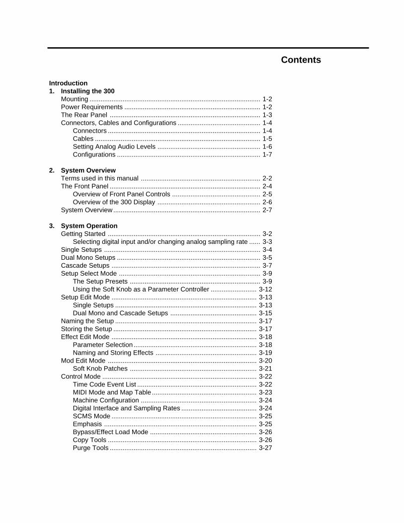
Introduction1. Installing the 300
Mounting ............................................................................................. 1-2Power Requirements .......................................................................... 1-2The Rear Panel .................................................................................. 1-3Connectors, Cables and Configurations ............................................. 1-4
Connectors ................................................................................... 1-4Cables .......................................................................................... 1-5Setting Analog Audio Levels ........................................................ 1-6Configurations .............................................................................. 1-7
2. System OverviewTerms used in this manual ................................................................. 2-2The Front Panel .................................................................................. 2-4
Overview of Front Panel Controls ................................................ 2-5Overview of the 300 Display ........................................................ 2-6
System Overview ................................................................................ 2-7
3. System OperationGetting Started ................................................................................... 3-2
Selecting digital input and/or changing analog sampling rate ...... 3-3Single Setups ..................................................................................... 3-4Dual Mono Setups .............................................................................. 3-5Cascade Setups ................................................................................. 3-7Setup Select Mode ............................................................................. 3-9
The Setup Presets ....................................................................... 3-9Using the Soft Knob as a Parameter Controller ......................... 3-12
Setup Edit Mode ............................................................................... 3-13Single Setups ............................................................................. 3-13Dual Mono and Cascade Setups ............................................... 3-15
Naming the Setup ............................................................................. 3-17Storing the Setup .............................................................................. 3-17Effect Edit Mode ............................................................................... 3-18
Parameter Selection ................................................................... 3-18Naming and Storing Effects ....................................................... 3-19
Mod Edit Mode ................................................................................. 3-20Soft Knob Patches ..................................................................... 3-21
Control Mode .................................................................................... 3-22Time Code Event List ................................................................. 3-22MIDI Mode and Map Table ......................................................... 3-23Machine Configuration ............................................................... 3-24Digital Interface and Sampling Rates ......................................... 3-24SCMS Mode ............................................................................... 3-25Emphasis ................................................................................... 3-25Bypass/Effect Load Mode .......................................................... 3-26Copy Tools ................................................................................. 3-26Purge Tools ................................................................................ 3-27

Contents, cont'd. 4. The Algorithms and their ParametersSingle Setup Algorithms ..................................................................... 4-2
Random Hall ................................................................................ 4-2Random Ambience ....................................................................... 4-8Rich Plate ................................................................................... 4-11Stereo Pitch Shift ....................................................................... 4-15Stereo Adjust .............................................................................. 4-18
"Split" Setup Algorithms .................................................................... 4-23Dual Delays ................................................................................ 4-23Split Chamber ............................................................................ 4-26Mono Pitch Shift ......................................................................... 4-29Compressor ................................................................................ 4-31PONS (Psychoacoustically Optimized Noise Shaping) .............. 4-33Small Stereo Adjust .................................................................... 4-34
5. The PresetsSingle Setup (and Effect) Presets ...................................................... 5-2Split Setup Presets and Their Effects ................................................. 5-6Split Setup Effect Descriptions ......................................................... 5-20Effect Preset Parameters ................................................................. 5-25
Effect Presets Using the Random Hall Algorithm....................... 5-25Effect Presets Using the Random Ambience Algorithm ............. 5-27Effect Presets Using the Rich Plate Algorithm ........................... 5-28Effect Presets Using the Stereo Adjust Algorithm ...................... 5-29Effect Presets Using the Stereo Pitch Shift Algorithm................ 5-30Effect Presets Using the Dual Delays Algorithm ........................ 5-31Effect Presets Using the Split Chamber Algorithm..................... 5-34Effect Presets Using the Mono Pitch Shift Algorithm ................. 5-36Effect Presets Using the Compressor Algorithm ........................ 5-36Effect Presets Using the PONS Algorithm ................................. 5-36Effect Presets Using the Small Stereo Adjust Algorithm ............ 5-36
6. Time Code OperationUsing Time Code ................................................................................ 6-2The Event List ..................................................................................... 6-3
Using time code to initiate program changes ............................... 6-3Snapping events .......................................................................... 6-4Editing the List .............................................................................. 6-4Trimming Time Codes in the Event List ....................................... 6-5Programming Parameter Glides ................................................... 6-6Things to Consider about Glides .................................................. 6-8Adding an event ........................................................................... 6-9Deleting an event ......................................................................... 6-9
Dumping the List to MIDI storage devices .......................................... 6-9Event List Log Sheet ........................................................................ 6-10

7. MIDI OperationMIDI Connections ............................................................................... 7-2Setting MIDI Channels ........................................................................ 7-3Dynamic MIDI ..................................................................................... 7-4Using MIDI Program Change Messages with the 300 ........................ 7-5
MIDI Table mode.......................................................................... 7-5Editing the MIDI Table .................................................................. 7-5
Real-time MIDI Effects Automation .................................................... 7-6Using Real-time SysEx and Non-registered Parameters ............. 7-6Using Dynamic MIDI® to transmit and receive MIDI
Controller Information ............................................................ 7-7Using SysEx and Dynamic MIDI® Patches ................................... 7-7
Controlling Multiple 300s .................................................................... 7-7MIDI Dumps of Current Setup, Event List, MIDI Table, and
All Registers ................................................................................. 7-8
8. TroubleshootingLow Voltage ........................................................................................ 8-2Overheating ........................................................................................ 8-2Common MIDI Problems .................................................................... 8-2Common Time Code Problems .......................................................... 8-3Common Digital Interfacing Problems ................................................ 8-3
9. MIDI Implementation Chart
10. Specifications

Congratulations on your purchase of the 300 Digital Effects System! The 300 notonly contains the finest sounds, as you've come to expect from Lexicon, itincorporates new functions that satisfy the needs of today's audio production.
Analog and Digital Audio InterfacingFor both analog and digital use the 300 takes full advantage of recent advancesin converter technology and combines them with flexible digital interfacing.
The A/D and D/A converters use oversampling techniques to minimize low-leveldistortion and provide linear phase characteristics. 64x oversampling Delta/Sigma conversion is used in the A/Ds; 8x oversampling is used in the D/As. Theresult is sonic transparency without the artifacts normally encountered inconversion.
The digital I/O simplifies interfacing with both the AES/EBU professional and theEIAJ consumer format. XLR, RCA and Optical connectors are provided for bothinput and output. The digital inputs of the 300 will automatically accept and lockto any AES/EBU/SPDIF format; the 300's digital output format is user-selectablefor feeding either professional or consumer equipment. This allows for formatconversion as well as using the high quality A/D converters to feed digitalrecorders. Control of additional Channel Status information is provided as well.
Dual DSP ArchitechtureThe 300 utilizes two proprietary high performance DSP engines. The configu-ration of these engines can be determined by the end-user to suit a particularaudio application. The Single Setup configuration unites both DSP engines.Two “split” configurations: Dual Mono and Cascade, allow each DSP engine torun a special program especially designed for “Split “ applications. The Singlealgorithms include: Random Hall, Random Ambience, Rich Plate, Stereo PitchShift, and Stereo Adjust. The “split" algorithms include: Dual Delays, Chamber,Mono Pitch Shift, Compressor, a special mastering dither program called PONS(Psychoacoustically Optimized Noise Shaping), and a small version of StereoAdjust.
Comprehensive Effects AutomationThe 300 makes effects automation available in three different ways. If you usetime code, the 300's Event List and Time Code Reader add a new twist to effectsprocessing. Each entry in the 50-item list contains a time code value and a 300effect preset/register number, allowing incoming time code to trigger setup andeffect changes, as well as setup and effect parameter glides. For changingeffects in music or changing rooms and environments for film and video, the300's time code capability opens new avenues to all time code users.
Dynamic MIDI® is included for real-time performance control and effects auto-mation. All parameters in the 300 can be patched to most MIDI controllers,allowing full control from remote devices. For full MIDI automation all parameterchanges can be recorded on any sequencer. For additional control, completeSystem Exclusive information is available.
Introduction

Lexicon SoundEven with the best functions and features, the heart of any signal processor isits sound. The 300 contains the very best of the Lexicon Sound — with newrefinements such as dynamic size parameters in the Reverb and Ambiencealgorithms. We have also included stereo and mono pitch shifting, delay effects,a mastering algorithm with precision level/balance controls and equalization.These sounds, combined with analog and digital audio I/O, time code basedeffect change, an internal LFO, and full MIDI automation result in a system thatprovides new creative options each time you use it.
We’re confident you’ll find that the 300’s combination of state-of-the-art soundand extraordinary versatility is exactly what you’re looking for — to make sureyou don’t miss out on anything, we’d like you to read this manual. It provides athorough explanation of both front panel and MIDI operation, digital and analoginterfacing, descriptions of the effects and presets, and complete MIDI Implem-entation data — all the information you need to access the full power of the 300.

1-1
Installing the 300
1Installing the300

Lexicon300 V 3.0 Owner's Manual
1-2
Mounting Before rack-mounting the 300, you may want to remove the four rubber feetattached to the bottom of the 300 chassis. Gently pry off the black plastic buttonsin the center of each foot, then remove the foot itself.
The 300 measures 19"W x 3.50"H x 13.9"D (483 x 90 x 353 mm). It uses twoEIA-standard rack spaces and can be mounted on any level surface or in astandard 19 inch (483 mm) rack. Whatever mounting method you use, makesure that the 300 is securely screwed into the rack adapter If the 300 is mountedin a rack or road case, support the rear of the chassis to prevent possibledamage from mechanical shock and vibration.
Power Requirements The 300 is equipped with a 3-pin IEC power connector and detachable cord,providing chassis grounding to the AC mains line. Plug the female end of thepower cord into the 300, and the male end into a wall outlet.
The 300 is internally wired to operate at 100, 120, 220 or 240 VAC. The operatingvoltage set at the factory is marked on a label attached to the rear panel. Checkthe label before applying power to the unit.
If the voltage must be changed, refer a qualified technician to the VoltageChangeover procedure in the 300 Service Manual.

1-3
Installing the 300
DO
PUSH
L IN
MIDI
OUT
DO
IN
R IN
INPUTGAIN
THRU
PUSH
L OUTR OUT
DIDI
EIAJ CP340PUSH
DIDO
PUSH
TIME CODE IN AES/EBU
COMM PORT
MIDI ConnectorsAC PowerStandard 3-pin IECpower connector.
CommunicationsPortDE9 connector, re-served for future en-hancements.
Input Gain2-position (In/Out)switch for matching in-put gain to the sourcebeing used.In = +16dB; Out = 0dB.
Out: Transmits MIDI data to other equipment.Thru: Passes any MIDI data received withoutchange.In: Receives MIDI information from other MIDIequipment such as master keyboard controllers,MIDI foot controllers, sequencers and synthesiz-ers.
The Rear Panel
3-pin XLR connectors, electronically balanced.
Either pin 2 or pin 3 can be used as high but, tomaintain polarity when transferring data to thedigital domain, pin 2 high convention is used byLexicon.
Pin 1 and either pin 2 or pin 3 of each output mustbe grounded for unbalanced operation.
Input impedance is 50kΩ unbalanced, and100kΩ balanced. Inputs accept input levels from-14dBu to +20dBu.
Output impedance is 75Ω, and levels up to+18dBu are possible.
Analog Inputs and Outputs
InputsThree connectors are provided for digital input:
AES/EBU professional format (1):3-pin female XLR
S/PDIF EIAJ CP-340 consumer format (2):unbalanced coaxial RCAoptical (fiber-optic)
One of these connectors may be selected fordigital input.
OutputsOutput format can be AES/EBU or S/PDIF.Output always goes to all three digital outputs.
Digital interfaces conform to AES 3-1992 (ANSIS4.40-1992). Input/output impedance levels ofthe AES/EBU connectors comply with theCCITT V.11 EIA RS-422A.
Digital Inputs and Outputs
Time Code In3-pin female XLR con-nector for input ofSMPTE (Drop or Non-drop), EBU, or FILMtime code formats.(Electronically bal-anced, 100mV p-pminimum)

Lexicon300 V 3.0 Owner's Manual
1-4
Connectors, Cablesand Configurations
Signal Mating Connector Description
L and R Analog XLR A3M Active balanced, pin 2 highAudio Input +2dBu min; +20dBu max
at 0dB setting
L and R Analog XLR A3F Active balanced; pin 2 highAudio Output -2dBu to +18dBu
at full scale output
AES/EBU XLR A3M Balanced RS-422Digital Input pin 2 high
AES/EBU XLR A3F Balanced RS-422Digital Output pin 2 high
S/PDIF RCA Unbalanced 75ΩEIAJ CP340Consumer DigitalInput and Output
S/PDIF EIAJ Consumer DigitalEIAJ CP340 Audio formatConsumer DigitalAudio OpticalInput and Output
Time Code XLR A3M Active balanced RS-422;pin 2 high, 100mV p-p
Input minimum
MIDI In 5-pin DIN Standard MIDI InterfaceMIDI OutMIDI Thru
Connectors
2 = high
3 = low
1 = ground
1 = ground
3 = low
2 = high
Female
Male
Pin 2 high by convention.

1-5
Installing the 300
Cables
Analog Audio I/Oand Time Code
For best performance, maintain balanced connections, and use high-quality,low-capacitance, twisted-shielded pair cable.
When connecting to single-ended, unbalanced devices, connect the low side tosignal ground at the unbalanced piece of equipment.
For mono connection, connect the left and right input channels in parallel.
Be careful to keep input and output to all channels wired consistently. Out-of-phase wiring can produce audible effects.
This interface requires balanced connections using high-quality, low-capaci-tance, controlled-impedance, data communication, twisted-shielded pair cable.It will not work reliably if microphone cable is used.
This interface is unbalanced but, because it carries digital signals, it requires theuse of 75Ω RG-59 coaxial cable.
Use commercially-available, consumer audio optical cable assemblies.
Use standard 5-pin DIN MIDI cable asemblies, available from your local dealer.
AES/EBUDigital Audio I/O
SPDIF (EIAJ CP340)Consumer Digital Audio I/O
SPDIF (EIAJ CP340)Consumer Digital AudioOptical I/O
MIDI IN, OUT and THRU
Below are recommended manufacturer's part numbers for cable and cableassemblies. In some cases, two types are specified: one with an overall braidshield for heavy use, and one with a foil shield for permanent installation.
Analog Audio and Time CodeBelden 8412 (microphone cable with braided shield)Belden 9461 (foil shield)
AES/EBUBelden 9271 (foil shield)Gotham GAC-2 AES-FRUMaximum recommended length: 100 ft (30M)
S/PDIF (EIAJ CP340) Consumer Digital AudioBelden 9259 (22 AWG conductor, .242 O.D.)Belden 8218 (27 AWG conductor, .150 O.D.)Maximum recommended length: 32 ft (10M)
S/PDIF (EIAJ CP340) Consumer Digital Audio OpticalToshiba TOCP174ySony POC-15Maximum recommended length: 16 ft (5M)

Lexicon300 V 3.0 Owner's Manual
1-6
LEVEL
When shipped, the 300 is set for the Analog I/O configuration. Once you haveconnected the analog inputs and outputs, you can set up the analog input andoutput levels. To do this, press the 300 front panel key marked LEVEL. Thedisplay will show:
Setting AnalogAudio Levels
The front panel PAGE UP and PAGE DOWN keys allow you to switch the displayfrom input levels (IN L and R) to output levels (OUT L and R).
When a line is selected, the boxes on the display will be lengthened. (Theillustration above shows the upper line selected.) If both lines on the display areselected, turning the Soft knob will alter both settings simultaneously. Thebuttons directly above and below the display act as toggle switches to individu-ally select and un-select these lines.
If additional gain is needed, the rear panel INPUT GAIN switch allows you to setunity gain of the 300 to 0dB (switch OUT), or to +16dB (switch IN).
Feed a 1kHz tone (or a musical signal at the maximum peak level used in yoursystem) to the 300. Use the front panel Soft knob to adjust the level so that thepeak input level falls just short of lighting the red overload LED. To set the outputlevel, press the front panel PAGE UP or PAGE DOWN key and use the Soft knobto set the output to provide appropriate levels for your console or system.
Press this button to toggleselection of INL on and off.
Press this button to toggleselection of INR on and off.
Actual level settings (in dB)are shown here.
This line is selected, and willchange as you turn the Softknob to give a visual indica-tion of the level settings
Level IndicatorsRed DSP Overload
Amber -3-6
Green -12-18-24-30-36-42
values are dB approximateLEVEL
INL (-10.0dB to +10.0dB)
INR (-10.0dB to +10.0dB)

1-7
Installing the 300
DO
PUSH
L IN
MIDI
OUT
DO
IN
R IN
INPUTGAIN
THRU
PUSH
L OUTR OUT
DIDI
EIAJ CP340PUSH
DIDO
PUSH
TIME CODE IN AES/EBU
COMM PORT
Effects Send (L)
Effects Send (R)
Channel Input orEffects Return (R)
Channel Input orEffects Return (L)
Configurations
Connection to amixing console'seffects sends
If you will be using a 300 as your primary effects unit, and your system includesa console with one or more auxiliary (effects) sends, connect the 300 as shownabove. In most applications, it is preferable to connect the 300 outputs to two ofthe console's input channel strips, panned full left and right, rather than theeffects returns. This allows the greatest flexibility in routing and equalization.
In this configuration the console controls are used to set the amount of effectheard—the 300's MIX control should be set for 100% wet. If you are using onlyone effects send, connect the left and right inputs of the 300 in parallel.
The following diagrams give a few examples of various possible configurationsfor interfacing to digital equipment.

Lexicon300 V 3.0 Owner's Manual
1-8
DO
PUSH
L IN
MIDI
OUT
DO
IN
R IN
INPUTGAIN
THRU
PUSH
L OUTR OUT
DIDI
EIAJ CP340PUSH
DIDO
PUSH
TIME CODE IN AES/EBU
COMM PORT
DO
PUSH
L IN
MIDI
OUT
DO
IN
R IN
INPUTGAIN
THRU
PUSH
L OUTR OUT
DIDI
EIAJ CP340PUSH
DIDO
PUSH
TIME CODE IN AES/EBU
COMM PORT
CONSOLEor
HEADPHONE AMP
RDAT MACHINEor
CD PLAYER
In
Out
Note: These digital connections can be made with fiberoptic, or XLR cables instead of 75Ω coaxial RCA cables.
CONSOLEor
HEADPHONE AMP
DIGITAL AUDIOor
DIGITAL VIDEOMACHINE
Source Machine
AES/EBU Format
AES/EBU Format
DIGITAL AUDIOor
DIGITAL VIDEOMACHINE
Destination Machine
Analog outputs for monitoring
Analog outputs for monitoring
Source Machine
S/PDIF Format
Analog outputs for monitoring
Destination Machine
RDATMACHINE
AES/EBU to AES/EBU
S/PDIF to S/PDIF
OutOut In
OutOut
Analog outputs for monitoring
S/PDIF Format
Out

1-9
Installing the 300
DO
PUSH
L IN
MIDI
OUT
DO
IN
R IN
INPUTGAIN
THRU
PUSH
L OUTR OUT
DIDI
EIAJ CP340PUSH
DIDO
PUSH
TIME CODE IN AES/EBU
COMM PORT
DO
PUSH
L IN
MIDI
OUT
DO
IN
R IN
INPUTGAIN
THRU
PUSH
L OUTR OUT
DIDI
EIAJ CP340PUSH
DIDO
PUSH
TIME CODE IN AES/EBU
COMM PORT
RDAT MACHINEor
CD PLAYER
CONSOLEor
HEADPHONE AMP
Analog outputs for monitoring
CONSOLEor
HEADPHONE AMP
RDATMACHINE
Destination Machine
Analog outputs for monitoring
Analog outputs for monitoring
DIGITAL AUDIOor
DIGITAL VIDEOMACHINE
Destination Machine
Source Machine
Analog outputs for monitoring
AES/EBU Format
S/PDIF Format
S/PDIF Format
AES/EBU to S/PDIFConversion
S/PDIF to AES/EBUConversion
Out
DIGITAL AUDIOor
DIGITAL VIDEOMACHINE
Source Machine
OutIn Out
OutOut OutAES/EBU Format
In

Lexicon300 V 3.0 Owner's Manual
1-10
DO
PUSH
L IN
MIDI
OUT
DO
IN
R IN
INPUTGAIN
THRU
PUSH
L OUTR OUT
DIDI
EIAJ CP340PUSH
DIDO
PUSH
TIME CODE IN AES/EBU
COMM PORT
DO
PUSH
L IN
MIDI
OUT
DO
IN
R IN
INPUTGAIN
THRU
PUSH
L OUTR OUT
DIDI
EIAJ CP340PUSH
DIDO
PUSH
TIME CODE IN AES/EBU
COMM PORT
CONSOLE, HEADPHONE AMPor
ANALOG MACHINE
CONSOLEor
MIKE PREAMP
CONSOLE, HEADPHONE AMPor
ANALOG MACHINE
ANALOGMACHINE
orCONSOLE
Source Machine
Analog Source
Analog Destination
DIGITAL AUDIOor
DIGITAL VIDEOMACHINE
Digital Destination
AES/EBU Format
AES/EBU Format
DIGITAL AUDIOor
DIGITAL VIDEOMACHINE
Destination Machine
Analog outputs for monitoring
Analog outputs for monitoring
Analog audio
Analog audio
ANALOG I/O andAES/EBU Digital Output
ANALOG I/O andAES/EBU to AES/EBU
DIGITAL AUDIOor
DIGITAL VIDEOMACHINE
Digital Source
AES/EBU Format
Analog audio
In InOut In
Out Out
OutIn In
Out Out
Analog audio
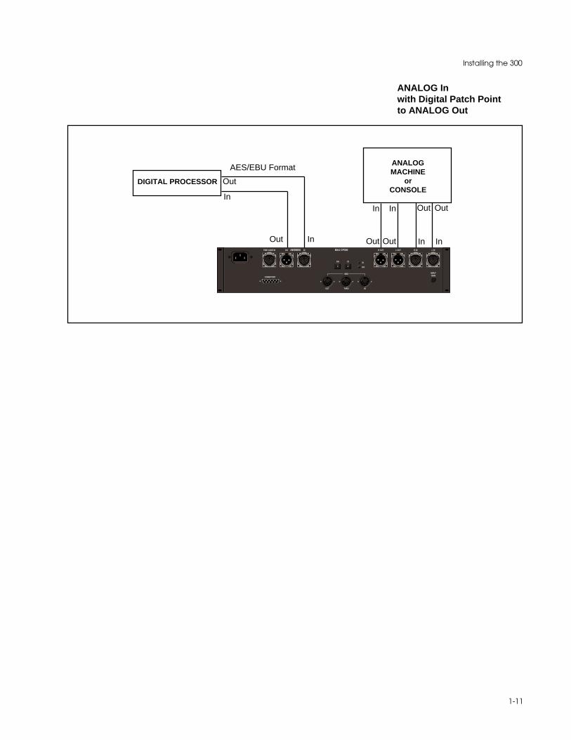
1-11
Installing the 300
ANALOG Inwith Digital Patch Pointto ANALOG Out
DO
PUSH
L IN
MIDI
OUT
DO
IN
R IN
INPUTGAIN
THRU
PUSH
L OUTR OUT
DIDI
EIAJ CP340PUSH
DIDO
PUSH
TIME CODE IN AES/EBU
COMM PORT
InOut
DIGITAL PROCESSOR
AES/EBU Format
In
Out
In
Out
In
Out
Out
In
Out
In
ANALOGMACHINE
orCONSOLE

2-1
System Overview
2System Overview

Lexicon300 V 3.0 Owner's Manual
2-2
In discussing 300 operation, the following terms are used.
AlgorithmThe 300 contains eleven algorithms. An algorithm is a set of instructions that tellsthe 300's audio processors how to process the input signal. One algorithmproduces pitch shift effects, another produces reverberation, etc. Algorithms arestored inside the 300 on ROM (Read-only memory) chips.
ConfigurationThe 300 can deliver two effects (one from each machine) simultaneously. Themanner in which the two machines relate to each other is called the configuration.The machines can be used with independent inputs and outputs (Dual Monoconfiguration), they can share the same stereo input signal (Single configura-tion), or the outputs of one machine can be fed into the input of another (Cascadeconfiguration).
EffectAn effect consists of an algorithm, the parameter values which create a specificsound, four associated patches, and an identifying name.
MachineThe 300 contains two processing modules, called Machine A and Machine B.Although both machines can run simultaneously, only one can be accessed fromthe front panel at any given time. A dedicated function key labeled MACH allowsfront panel selection of either Machine A or Machine B.
PagesBecause effects (and other modes of operation) have more parameters than canbe displayed at one time, parameters are grouped into several pages. You movebetween pages by pressing the dedicated function keys labeled PAGE UP andPAGE DOWN.
ParameterEach algorithm has a set of parameters (controls) that uniquely characterize it.The settings of the parameters can be changed to create radically differentsounds from a single algorithm.
PatchA patch is a routing assignment that allows one of the 300's parameters to bedriven by a source controller (LFO, footswitch, mod wheel, etc.)
Register/PresetRegisters are simply memory locations where you can store your own setups andeffects. Presets are factory-installed setups and effects. The presets cannot beoverwritten, but they can be modified and stored as custom setups in theregisters. Registers and presets are differentiated on the 300 display by the initialR (Register) or P (Preset) before their number.
Terms usedin this manual
2-3
System Overview
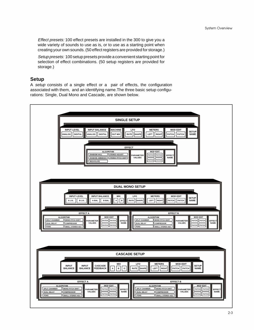
Effect presets: 100 effect presets are installed in the 300 to give you awide variety of sounds to use as is, or to use as a starting point whencreating your own sounds. (50 effect registers are provided for storage.)
Setup presets: 100 setup presets provide a convenient starting point forselection of effect combinations. (50 setup registers are provided forstorage.)
SetupA setup consists of a single effect or a pair of effects, the configurationassociated with them, and an identifying name.The three basic setup configu-rations: Single, Dual Mono and Cascade, are shown below.
SINGLE SETUP
MACHINE
OUT MIX
INPUT BALANCE
ANALOG DIGITAL
INPUT LEVEL
ANALOG DIGITAL
MOD EDIT
PATCH PATCH
LFO
RATE SHAPE
METERS
LEFT RIGHTSETUPNAME
EFFECT
EFFECTNAME
MOD EDIT
PARAMETERVALUES
ALGORITHM
PATCH PATCH
PATCH PATCHRANDOM AMBIENCE STEREO PITCH SHIFT
RICH PLATE
RANDOM HALL STEREO ADJUST
DUAL MONO SETUP
MIX
A
INPUT BALANCEINPUT LEVEL
A LVL B LVL
MOD EDIT
PATCH PATCH
LFO
RATE SHAPE
METERS
LEFT RIGHTSETUPNAME
EFFECT A
EFFECTNAME
MOD EDIT
PARAMETERVALUES
ALGORITHM
PATCH PATCH
PATCH PATCHDUAL DELAY COMPRESSOR
PONS
SPLIT CHAMBER MONO PITCH SHIFT
A BAL B BAL B
EFFECT B
EFFECTNAME
MOD EDIT
PARAMETERVALUES
ALGORITHM
PATCH PATCH
PATCH PATCHDUAL DELAY COMPRESSOR
PONS
SPLIT CHAMBER MONO PITCH SHIFT
SMALL STEREO ADJ SMALL STEREO ADJ
CASCADE SETUP
MIX
A
MOD EDIT
PATCH PATCH
LFO
RATE SHAPE
METERS
LEFT RIGHTSETUPNAME
EFFECT A
EFFECTNAME
MOD EDIT
PARAMETERVALUES
ALGORITHM
PATCH PATCH
PATCH PATCHDUAL DELAY COMPRESSOR
PONS
SPLIT CHAMBER MONO PITCH SHIFT
B
EFFECT B
EFFECTNAME
MOD EDIT
PARAMETERVALUES
ALGORITHM
PATCH PATCH
PATCH PATCHDUAL DELAY COMPRESSOR
PONS
SPLIT CHAMBER MONO PITCH SHIFT
CASCADEFEEDBACK
INPUTBALANCE
INPUTBALANCE O
SMALL STEREO ADJ SMALL STEREO ADJ

Lexicon300 V 3.0 Owner's Manual
2-4
300 DIGITAL EFFECTS SYSTEM
MIDI
48 kHz44.1 kHz32 kHz
CONTROL
UP
PAGE
DOWN
7 8 9
4 5 6
1 2 3
— 0ENTER
PAGE
SETUP
SELECT
MACH
STORE
VALUE
SETUP
EDIT
EFFECT
EDIT
MOD
EDIT
BYPASS
A
BYPASS
B
POWER
LEVEL
PowerPower on/off.
Numerical KeypadUsed for numeric entryof program numbers(as an alternative toSoft Knob selection)and for time code en-tries.
Dedicated-function keys
Setup Select: Used toselect and run setups.
Mach: In appropriateconfigurations, allowsselection of either ofthe 300's two process-ing modules (MachineA and Machine B) forfront panel control.
Store: Used to memo-rize effects and set-ups.
Value: Used to displayparameter values forSoft button or Softknob adjustment.
Control: Used to ac-cess system parame-ters.
Setup Edit: Used tocreate or modify thecurrent setup.
Effect Edit: Used toadjust the parametersof effects.
Mod Edit: Used tocreate patches.
Page Up/DownAllow access to dis-play pages of adjust-able parameters.
The Front Panel
LevelUsed to adjust Analoginput and output levels(in conjunction withthe Soft knob and thePage Up/Down keys).Levels are shown onthe LED bar graphs di-rectly above theLEVEL key. The lower6 LEDs are green, fol-lowed by 2 amber, andone red - indicatingoverload.
Soft buttonsEach of these eightbuttons is used to se-lect the parameterdisplayed directlyabove or below. Onceselected, parameterscan be changed incre-mentally by additionalbutton pushes, or theycan be adjusted bythe Soft knob.
Soft knobUsed to adjust para-meters displayed andselected with the Softbuttons.
BypassEnable digital bypassof Machine A or B toprovide an unproc-essed signal, or tomute the effect input.
MIDI and SampleRate LEDsThe amber MIDI LEDindicates activity overthe designated MIDIchannels. The sam-pling rate of the 300 isshown by the greenLEDs.
Note: 32kHz samplingrate is not supported.

2-5
System Overview
CONTROLSETUP
SELECT
MACH
STORE
VALUE
SETUP
EDIT
EFFECT
EDIT
MOD
EDIT
Overview ofFront Panel Controls
The 300 front panel has been designed for ease-of-use and intuitive access toall of the 300's functions.
In general the user will be operating in one of the following modes of operation,each of which is accessed from the dedicated keypad on the front panel. Eachmode key has an LED which lights when the key is activated. The functions ofthe VALUE and STORE keys are discussed later in this section.
SETUP SELECTIt is from Setup Select mode that setups are selected and loaded. Setups canbe selected with the Soft knob, or by entering a setup number on the numerickeypad and then pressing ENTER.
CONTROLControl mode provides access to global system functions which include: DigitalI/O Configuration, MIDI Channels, Modes, and Effect Change tables. SelectingControl mode does not interrupt the audio operation of the 300.
MACHThis button allows you to toggle between the 300's two DSP engines. Eachmachine can process audio continuously and simultaneously. However, thefront panel can only actively control one effect at a time.Each time you pressMACH, the 300 switches control; the display indicates whether Machine A or Bis being controlled.
SETUP EDITThis mode is used to modify the current setup. In this mode you can select theeffect for the setup, and the name assigned to the setup
EFFECT EDITIn this mode you can modify the effect used in the current setup, and change thename of the effect. The available parameters for each effect are organized ontodisplay pages. The algorithms and their parameters are discussed in detail inChapter 4.
MOD EDITIn Modulation Edit you can assign MIDI and Soft knob patches.
Switching between these various modes is as simple as pressing a button. Theoperation of the 300 in each of these modes is discussed in the followingsections.

Lexicon300 V 3.0 Owner's Manual
2-6
LEVEL
CONTROLSETUP
SELECT
MACH
STORE
VALUE
SETUP
EDIT
EFFECT
EDIT
MOD
EDIT
Overview of the300 Display
Generally, the display will indicate a page of parameters, any of which can beselected by pressing the button directly above or below it. In the example below,the "RTIM" parameter has been selected and is highlighted by an underscorecursor on the display.
RTIM SIZE ROLL PDLY
RLVL TDCY BASS XOVR
Once selected, parameters can be adjusted over their entire range with the Softknob. The parameter and its current value will appear on the display as long asthe Soft knob is being adjusted.
Pressing the front panel VALUE key will display all of the current parametervalues for the selected page. in this example, pressing VALUE will cause thefollowing display to appear:
2.0s 37.1M 2.9k 22m
FULL 3.6k 2X 0.5k
Here again, turning the Soft knob will adjust the selected parameter over itsentire range; the buttons will select other parameters for adjustment.
The PAGE UP and PAGE DOWN keys are used to access various pages ofadditional parameters (or parameter values) which can then be edited via theSoft knob.
UP
PAGE
DOWN
PAGE

2-7
System Overview
DigitalIn
AnalogIn
XLR
RCA
OPT
48 kHz44.1 kHz
PLLSample Rate
(SR)
SR
A/D
0.0 or +16dBRear PanelGain Switch
-10 to +10dBInput Level
Control
Panel, MIDI and Time Code Program Change
-10 to +10dBOutput Level
Control
AnalogOut
DigitalOut
EffectDigitalIn
DSP
DigitalOut
D/A
SR
SR
XLR
RCA
OPT
Emph Emph
DSP
System OverviewThe 300 presents you with an incredible number of choices — all of which canbe made through the front and rear panel. Although you could certainly operatethe 300 by setting each I/O configuration and effect parameter by hand each timeyou use it, you probably wouldn't enjoy it — so we've tried to organize the 300so that its considerable flexibility doesn't become an obstacle. Before digginginto the details of operation presented in this manual, you may find this briefoverview useful.
The block diagram shown below illustrates the basic flow of audio through the300. Analog and/or digital audio enters on the left. Each is conditioned andtranslated as required and, in the case of digital audio, a sample clock isextracted. The resultant digital audio streams are sent to effect processing, thenconverted to appropriate analog and digital outputs (on the right).
As you can see from the figure, the 300 has a rich set of I/O capabilities, withmany choices available to the user, including:
Sample RateAnalog or Digital Input connectorDigital and Analog Emphasis/De-emphasisDigital Output format (AES or SPDIF)Digital Copy (SCMS) and Emphasis bit manipulationProcessor Configuration
The I/O organization is part of the 300's Control Mode. Other items which formpart of the global operaton of the box are: Time Code event list viewing andediting, MIDI Mapping Tables, Purge functions for User Registers,Copy Tools,and Bypass button functions.

Lexicon300 V 3.0 Owner's Manual
2-8
By far the most important aspect of the 300 is the Setup and its association tothe digital effect(s) that you want to use. The 300 has three types of Setups:Single, Dual Mono, and Cascade. Each is strikingly different and together theyprovide incredible audio possibilities.
Each Setup includes one or more effects along with other items such asmachine input(s) and source balance(s), the relationship between wet (effect)and dry (input) mixing for each machine, meter functions, LFO rates andshapes, and a naming function. In addition, there are two(2) modulation patcheswhich can link source controllers to two Setup parameters.
To simplify the choice among the many possible effect and system routings, the300 is shipped with 100 Setup Presets. (The organization of the Setup Presetsis shown to the left.) These factory presets cannot be overwritten, but can bemodified and stored as User Setups in any of 50 Setup Registers.
Audio effects, of course, are what the 300 is all about, and a total of 100 EffectPresets are provided for loading into the three Setup types. Five algorithms canbe loaded into Single Setups: Random Hall, Random Ambience, Rich Plate,Stereo Pitch Shift, and Stereo Adjust. Six different algorithms can be loaded intothe "split" Setups (Dual Mono and Cascade): Dual Delays, Split Chamber, MonoPitch Shift, Compressor, PONS, and Small Stereo Adjust. (The organization ofthe Effect Setups is also shown to the left.)
Each algorithm has its own control parameters. Random Hall, for example, has28. The front panel EFFECT EDIT key and the Soft knob, allow effectparameters to be adjusted along a range of values, dramatically altering theaudible effect of the algorithm. An effect can also activate as many as 4 patches,each linking a source controller to a parameter. This MOD EDIT function isintrinsically mapped as an extension of the EFFECT EDIT function. Savingeither saves the other. (The Effect Presets cannot be overwritten, but can bemodified and stored as custom Effects in any of 50 Effect Registers.)
In summary, the 300 is organized into setups and effects. Setups are collectionsof many decisions, including DSP routing, Input levels, Source, Balances, LFORate and Shape, and an Effect or Effects. These selections are groupedtogether, named and stored so they can be called up with a single user action.Each Effect included in a Setup contains an algorithm, a complete set ofparameters, and 4 patches. As with Setups, Effects can be loaded, copied,edited, named, and stored, as well as dumped and recalled via MIDI.
CONTROLSETUP
SELECT
MACH
STORE
VALUE
SETUP
EDIT
EFFECT
EDIT
MOD
EDIT
Setup Presets
The Setup Presets are organizedas follows:
101-150 = Single Setups201-225 = Dual Mono Setups301-325 = Cascade Setups
Single Set-Ups contain one ef-fect running in a single unifiedmachine (both DSP enginesworking as one).
Dual Mono and Cascade can bethought of as “split” configura-tions, and are capable of simulta-neously running two different (oridentical) effects.
Effect Presets
Effect Presets are organized asfollows:
101-115 = Random Hall Presets201-210 = Random Ambience301-308 = Rich Plates401-409 = Stereo Adjust501-508 = Stereo Pitch Shift
These can only be loaded intoSingle Setups (101-150).
601-616 = Dual Delays701-720 = Split Chambers801-810 = Mono Pitch Shift901-902 = Compressor001 = the PONS Program forMastering Applications010 = Small Stereo Adjust
These can only be loaded into“Split” Setups (201-325).

2-9
System Overview
The 300's Control Mode provides access to general global parameters andmiscellaneous functions. Selecting Control mode does not interrupt the audiooperation of the 300.
There are 9 Control mode pages:
1. Set-up Configuration and Input type select (Analog and/or Digital),
2. Analog sample rate select, Digital locked, Digital input connector type,Digital Input format display and Digital Output format selection.
3. SCMS Detect and select
4. Digital emphasis detect and select
5. Effect Load select(Bypass, Mute) and Bypass function (Input mute, Bypass
6. Copy Protect/Copy Tools for Setups, Effects, and MIDI Mod Edits
7. Purge (Delete) Tools for Time Code Event List,All Registers, All Effects,MIDI Map Table, and return to Factory Initialization.
8. Time Code Event List Management
9. MIDI Mode and MIDI Map Table
Note: The 300 Digital Effects System is shipped from the factory running in anAnalog Input, 48kHz mode with Setup Preset S:P101 SINGLE running EffectPreset EA: P101 Large Hall.
If you are already familiar with the operation of the 300 and wish to change theInput to a Digital Type, simply enter Control mode and make your selections.
If you have no previous experience with the 300, we suggest you remain in theanalog mode and read on...

3-1
System Operation
3System Operation
Lexicon300 V 3.0 Owner's Manual
3-2
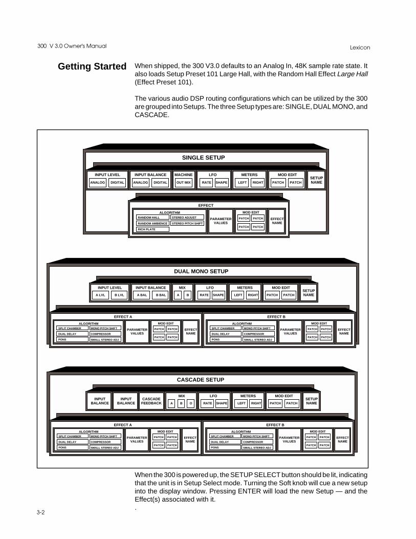
When shipped, the 300 V3.0 defaults to an Analog In, 48K sample rate state. Italso loads Setup Preset 101 Large Hall, with the Random Hall Effect Large Hall(Effect Preset 101).
The various audio DSP routing configurations which can be utilized by the 300are grouped into Setups. The three Setup types are: SINGLE, DUAL MONO, andCASCADE.
Getting Started
SINGLE SETUP
MACHINE
OUT MIX
INPUT BALANCE
ANALOG DIGITAL
INPUT LEVEL
ANALOG DIGITAL
MOD EDIT
PATCH PATCH
LFO
RATE SHAPE
METERS
LEFT RIGHTSETUPNAME
EFFECT
EFFECTNAME
MOD EDIT
PARAMETERVALUES
ALGORITHM
PATCH PATCH
PATCH PATCHRANDOM AMBIENCE STEREO PITCH SHIFT
RICH PLATE
RANDOM HALL STEREO ADJUST
When the 300 is powered up, the SETUP SELECT button should be lit, indicatingthat the unit is in Setup Select mode. Turning the Soft knob will cue a new setupinto the display window. Pressing ENTER will load the new Setup — and theEffect(s) associated with it..
CASCADE SETUP
MIX
A
MOD EDIT
PATCH PATCH
LFO
RATE SHAPE
METERS
LEFT RIGHTSETUPNAME
EFFECT A
EFFECTNAME
MOD EDIT
PARAMETERVALUES
ALGORITHM
PATCH PATCH
PATCH PATCHDUAL DELAY COMPRESSOR
PONS
SPLIT CHAMBER MONO PITCH SHIFT
B
EFFECT B
EFFECTNAME
MOD EDIT
PARAMETERVALUES
ALGORITHM
PATCH PATCH
PATCH PATCHDUAL DELAY COMPRESSOR
PONS
SPLIT CHAMBER MONO PITCH SHIFT
CASCADEFEEDBACK
INPUTBALANCE
INPUTBALANCE O
SMALL STEREO ADJ SMALL STEREO ADJ
DUAL MONO SETUP
MIX
A
INPUT BALANCEINPUT LEVEL
A LVL B LVL
MOD EDIT
PATCH PATCH
LFO
RATE SHAPE
METERS
LEFT RIGHTSETUPNAME
EFFECT A
EFFECTNAME
MOD EDIT
PARAMETERVALUES
ALGORITHM
PATCH PATCH
PATCH PATCHDUAL DELAY COMPRESSOR
PONS
SPLIT CHAMBER MONO PITCH SHIFT
A BAL B BAL B
EFFECT B
EFFECTNAME
MOD EDIT
PARAMETERVALUES
ALGORITHM
PATCH PATCH
PATCH PATCHDUAL DELAY COMPRESSOR
PONS
SPLIT CHAMBER MONO PITCH SHIFT
SMALL STEREO ADJ SMALL STEREO ADJ

3-3
System Operation
If you wish to change the Analog Sampling rate or to slave-lock the 300 to anexternal digital device or to external system word clock, you must go into the300’s Control mode. To do this, simply press the CONTROL button. Press PAGEDOWN twice to view Page Three, the Machine Configuration page.
This page allows you to define Input type, with the currently selected typeunderscored. (When shipped, this will be the factory default Input type, ANA-LOG.)
Selecting digital Input,and/or changing analogsampling rate
Before turning the Soft knob to change the Input type, press PAGE DOWN todisplay the Digital Input and Sampling Rate page. This page allows you to selectdifferent types of Analog and Digital I/O parameters.
Inp: Indicates the Digital Format if properly locked. If ***** appears, the 300 isnot locked to an external digital sync.
Clk: Allows the engineer to select the Analog Sampling rate. Pushing either ofthe 2 buttons above this label first selects the parameter. You can then push thebutton again to toggle to 44kHz, or you can use the Soft knob.
Out: Allows you to select AES Professional or SPDIF(Sony/Phillips DigitalInterFace) Consumer as output formats.
Din: Allows selection from among the three(3) different Digital Input Connectors:XLR, RCA, and OPTical.
If you wish to operate the 300 in the digital domain, push either of the 2 buttonsunder the Din label to select that parameter. (The selected parameter will beunderscored.) Use the Soft knob or multiple button pushes to select the DigitalInput connector which suits your studio rig.
Press PAGE UP to display the Input I/O selection screen. In the SINGLE modethere are three choices: ANALOG, DIGITAL, or ANAlog + DIGital. Use the Softknob to select DIGITAL, then press PAGE DOWN to display the next screen.
Mach Conf : Single
I : ANALOG 0 : ana+dig
Inp : ***** Clk : 48kHz
Out : AES Din : XLR
Lexicon300 V 3.0 Owner's Manual
3-4
If the system is properly locked, the Inp field should now be displaying either“AES” or “SPDIF”. If the system is not properly locked to the incoming word clock,the following error message will be displayed:
BAD/NO DIGITAL INPUTCheck Din connector!
Go back and check all your cables.
Once you’ve configured the Analog or Digital audio type, return to the SetupSelect mode by pressing SETUP SELECT.
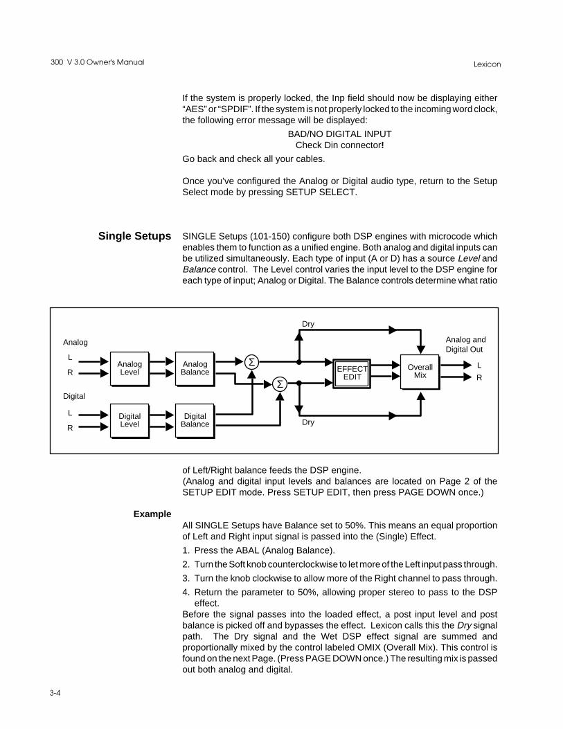
SINGLE Setups (101-150) configure both DSP engines with microcode whichenables them to function as a unified engine. Both analog and digital inputs canbe utilized simultaneously. Each type of input (A or D) has a source Level andBalance control. The Level control varies the input level to the DSP engine foreach type of input; Analog or Digital. The Balance controls determine what ratio
L
RAnalogLevel EFFECT
EDITOverall
Mix
Dry
Σ
Analog
Digital
Analog andDigital Out
L
R
L
R
DigitalLevel
AnalogBalance
DigitalBalance
Σ
Dry
of Left/Right balance feeds the DSP engine.(Analog and digital input levels and balances are located on Page 2 of theSETUP EDIT mode. Press SETUP EDIT, then press PAGE DOWN once.)
All SINGLE Setups have Balance set to 50%. This means an equal proportionof Left and Right input signal is passed into the (Single) Effect.
1. Press the ABAL (Analog Balance).
2. Turn the Soft knob counterclockwise to let more of the Left input pass through.
3. Turn the knob clockwise to allow more of the Right channel to pass through.
4. Return the parameter to 50%, allowing proper stereo to pass to the DSPeffect.
Before the signal passes into the loaded effect, a post input level and postbalance is picked off and bypasses the effect. Lexicon calls this the Dry signalpath. The Dry signal and the Wet DSP effect signal are summed andproportionally mixed by the control labeled OMIX (Overall Mix). This control isfound on the next Page. (Press PAGE DOWN once.) The resulting mix is passedout both analog and digital.
Example
Single Setups

3-5
System Operation
NOTE: Most studio applications assume a100% Wet mix. Most SINGLESetups are set with OMIX at 100% Wet. However, it is possible that some pre-fade sends to the 300 will require the mix to be set to another value.
Dual Mono Setups (Setup Presets 201-225) are “Split” configurations. Turn theSoft knob to cue up different Dual Mono Setups. The top line of the displayindicates the Setup Preset number and the two types of effects loaded in theSetup. The bottom display line shows which “Split” Effect is loaded into whichmachine. In the Dual Mono”Split” configuration each DSP engine, Mach A andMach B, can run special Split Effect Algorithms and Presets .
Analog and/or Digital formats can be input into the 300. When only one input type(analog or digital) is specified, we refer to the format as "Fixed."
When Analog is selected as the main Input source, the Digital I/O port can beplaced in a pre or post effect patch point. Conversely, if the Digital input isselected as the main input source, Analog I/O connections can be used as apatch point.
Dual Mono Setups
L
R
ALevel
EFFECTEDIT A
LOut
ROut
Analog orDigital
BLevel
ABalance
BBalance
Dry
EFFECTEDIT B
AMix
BMix
Dry
Patch Points
Patch Points
Fixed Format

Lexicon300 V 3.0 Owner's Manual
3-6
When both Analog and Digital are specified to operate as MAIN Inputs, we referto it as "Mixed Format." The Mixed format gives you the option of using the left,right, or summed mono input signals of each type of input(Analog or Digital). Inthis format, patch points are given up. The parameters for determining whatblend of Left/Right is passed to each Machine (A and B), are “A BAL" and “BBAL", located on Page Two of the Setup Edit mode.
Mixed Format
L
R
ALevel
EFFECTEDIT A
LOut
ROut
Analog
BLevel
ABalance
BBalance
Dry
EFFECTEDIT B
AMix
BMix
Dry
R
DigitalL
The determination of Fixed vs. Mixed formats is set in Control mode on PageThree: the Machine Configuration page. Selecting ANALOG or DIGITAL on thispage specifies the Fixed format.
If you want to input both analog and digital audio (Mixed format), press CTRL toget to Control mode. Press PAGE UP or PAGE DOWN to view the MachineConfiguration page. The leftmost button on the bottom row selects I: ANALOGor DIGITAL. In Dual Mono Setups, the selections also include: A>L D>R, andD>L A>R. Turn the Soft knob so that the display reads:
Mach Conf: Dual-Mono
I : A>L D>R O : a>l d>r
In this format, analog audio feeds the Input to the Left Processor (Machine A);digital audio feeds the Input to the Right Processor (Machine B).
Machine A audio comes out Analog left (and digital left)
Machine B audio comes out Digital right (and analog right)
All Dual Mono setups have the ABAL and BBAL set to Left-CHannel and RightCHannel respectively. This assumes a fixed format type of audio configuration.If you elect to work in a Fixed format, all Dual Mono setups will require individualadjustment of ABAL and BBAL to 50%.

3-7
System Operation
When working in a fixed format (with only analog or digital Dual Mono inputs),each machine has its own level control. The output of each level adjustment issplit to each source balance control. Each Dual Mono Setup Preset defaults toABAL panned to LEFT ONLY, and BBAL panned to RIGHT ONLY. (AIN, ABAL,BIN, and BBAL are located on Page Two of the Setup Edit mode.)
*If you had, for example, a piano in the left input and a voice in the right input andboth Balances were set to 50%, a summed input with equal amounts of piano andvoice would be passed to each DSP engine.
A dry signal is picked off before the signal passes into each Split DSP Effect. Themono wet output of each DSP effect sums with the dry signal and is proportion-ally mixed under the MIX controls: AMIX and BMIX. The third SETUP EDIT pagecontains AMIX and BMIX.) Continuing with the above example, if both AMIX andBMIX were set to 0%WET (or 100% DRY), you could use AIN and BIN as levelcontrols, mixing two independent signals to mono as part of an analog or digitalprocess.
Cascade Setups are another type of “Split” configuration. They are numbered301-325 in Setup Select mode. While in Setup Select mode, you can use the Softknob to locate the Cascade Setups. Pressing ENTER will load two split typeprograms: one in Machine A, the other in Machine B.
Cascade Setups
L
R
InputLevel
InputBalance
Feedback
AMix
EFFECTEDIT A
EFFECTEDIT B
BMix
OverallMix
Feedback
Dry
Dry
LOut
ROut
ΣΣ
Analog orDigital
Patch Points
Patch Points

Lexicon300 V 3.0 Owner's Manual
3-8
From the 300's Control mode, there are two input format selections availablewhen running Cascade programs: Analog or Digital. If Analog is selected as themain input type, then the Digital Input can be used as a patch point — either Pre-Machine A, Mid A - B, or Post Machine B. As in the other setups, there are Inputlevel and source Balance Controls. Cascade setups, however, have three mixcontrols. AMIX proportions the dry signal to A's wet signal. BMIX proportionsthe resulting A output with Machine B's output. OMIX takes the resulting A+Bmix and blends(mixes) it with the dry signal which is picked off before EFFECTA.Cascade setups also include an overall feedback control which routes the Boutput back to Machine A's input. Be careful!! This parameter can wipe outtweeters, woofers and ears if used too liberally.
If the sum of the feedback parameters in EFFECT A , EFFECT B and theabove-mentioned overall Feedback parameter is greater than 100%,runaway feedback will occur.
For example, assume Machine A is running a Dual delay effect with Delay1Feedback set to 40% and Delay3 Feedback set to 40%. Machine B is runninga Mono Shift program with the feedback parameter set to 40%. The totalamount of feedback in the system is 80%. So far, so good.... that is until youadd more than 20% Cascade Feedback. BE CAREFUL!!!!
CASCADE Setups offer an amazing number of effect combinations: Chambersinto Delays, Pitch Shifts into Chambers, Flanges into Delays, Reverbs intoCompressor, etc. You experiment, name, and store new combinations into UserSetup Registers. Remember, Input levels, Source Balances, Mix Balances,Feedback amounts, LFO type, and, of course, the two effects are part of thestorable Setup.
Note:

3-9
System Operation
Setup Select mode allows you to select and run setup presets and registers.
The 300 is shipped with 100 setup presets, as well as 50 setup registers forstoring your modified setups. The setup presets provide a convenient startingpoint for selecting the audio DSP routing you want to use. Note: Presets markedwith an asterisk (*) have a Soft knob patch.
Single Setup PresetsSetup # Setup Name Mach Effect # Effect Name
P101 Large Hall A P101 Large HallP102 Medium Hall A P102 Medium HallP103 Small Hall A P103 Small HallP104 *Church A P104 *ChurchP105 *Rooms A P105 *RoomsP106 RehursalRoom A P106 Rehursal HallP107 *Chamber A P106 *ChamberP108 LiveDrumRoom A P108 LiveDrumRoomP109 *Studio A A P109 *Studio AP110 *Studio B A P110 *Studio BP111 *Brick Wall A P111 *Brick WallP112 *Deep End A P112 *Deep EndP113 Oil Tanker A P113 Oil TankerP114 *Synth Hall A P114 *Synth HallP115 Dance Hall A P115 Dance Hall
P116 *Ambience A P201 *AmbienceP117 In A Room A P202 In A RoomP118 Stairwell A P203 StairwellP119 *Hangar A P204 *HangarP120 MarbleFoyer A P205 Marble FoyerP121 EarlyReflect A P206 EarlyReflectP122 Lecture Hall A P207 Lecture HallP123 *CarInterior A P208 *CarInteriorP124 Score Stage A P209 Score StageP125 Gate It!! A P210 Gate It!!
P126 *Rich Plate A P301 *Rich PlateP127 Glossy Plate A P302 Glossy PlateP128 Warm Plate A P303 Warm PlateP129 Perc Plate A P304 Perc PlateP130 Contem-Plate A P305 Contem-PlateP131 *EKO Plate A P306 *EKO PlateP132 Bright Plate A P307 Bright PlateP133 *Round Plate A P308 *Round Plate
P134 StereoAdjust A P401 Stereo AdjustP135 Phase Invert A P402 Phase InvertP136 2 Frame Dly A P403 2 Frame DlyP137 3 Frame Dly A P404 3 Frame DlyP138 4 Frame Dly A P405 4 Frame DlyP139 MS Decode A P406 MS DecodeP140 *MultiEchoes A P407 *MultiEchoesP141 LFO Panner A P408 LFO PannerP142 Telephone A P409 Telephone
P143 *Stereo Shift A P501 *Stereo ShiftP144 Octave Down A P502 Octave DownP145 Vox Chorus A P503 Vox ChorusP146 Pole Flange A P504 Pole FlangeP147 Bulkie Roll A P505 Bulkie RollP148 Heavy Roll A P506 Heavy RollP149 *Going, Going A P507 *Going, GoingP150 Zorch! A P508 Zorch!
Setup Select Mode
Algorithms:
The Setup Presets
Random Hall
Random Ambience
Rich Plate
Stereo Adjust
Stereo Pitch Shift

Lexicon300 V 3.0 Owner's Manual
3-10
Dual Mono Setup PresetsSetup # Setup Name Mach A Effect # Name Mach B Effect # Name
P201 Rev/Rev 701 Chamber 702 Key ChamberP202 Rev/Dly 703 Drum Chamber 607 LFO:Faze DelaysP203 Rev/Pch 705 Guitar Room 802 Guit ShiftP204 Rev/Comp 707 “U”Chamber 901 EZ Comp2:1P205 Dly/Dly 609 Chorus 612 Chorus+EKOzP206 *Dly/Pch 601 *Dual Delays 804 Sky DownP207 Dly/Comp 602 Space Delays 902 DrumComp3:1P208 *Pch/Pch 803 *Up Shift 806 Echo downP209 Pch / Comp 810 Vocal Shift 902 DrumComp3:1P210 Comp/Comp 901 EZ Comp 902 DrumComp 3:1P211 Slow Spin 607 LFO:FazeDlys 609 ChorusP212 WideFlang 605 OverTheTop1 606 OverTheTop2P213 X-Traffic 612 Chorus+EKOz 610 *Sky DelaysP214 *GearUp 803 *Up Shift 805 Env*EKOShiftP215 TwoRooms 715 Joe's Garage 709 BasementP216 TwoHalls 720 Recital Hall 710 Big HallP217 *Verbs 717 *Drum Rooms 711 *Great RoomP218 *RevPan 707 “U”Chamber 708 *’L’ChamberP219 Up&Down 807 HalfStepsUp 808 HalfStepsDnP220 MyGuitar 802 Guit Shift 614 Env:PeakP221 EnvSpooge 614 Env:Peak 608 Env:PhazerP222 Flng&Dlys 616 Negative Flang 602 Space DlysP223 *Dly Daze 604 *3VoiceDlys 603 *PingoPongoP224 Clusters 612 Chorus+EKOz 604 *3Voice DlysP225 2 Flanges 606 OverTheTop2 804 Sky Down
Cascade Setup PresetsSetup # Setup Name Mach A Effect # Name Mach B Effect # Name
P301 Rev->*Dly 701 Chamber 601 *Dual DelaysP302 *Dly->*Rev 601 *Dual Delays 714 *Joe's B&GP303 Rev->Pch 707 “U”Chamber 802 Guit ShiftP304 Pch->Rev 804 Sky Down 703 Drum ChamberP305 Rev->Comp 705 Guitar Room 901 EZ Comp 2:1P306 Comp->Rev 902 Drum Comp 3:1 709 BasementP307 Dly->Pch 609 Chorus 801 Mono ShiftP308 Pch->*Dly 810 Vocal Shift 603 *PingoPongoP309 *Dly->Comp 604 *3Voice Dly 901 EZ Comp 2:1P310 Comp->*Dly 901 EZ Comp 2:1 613 *Wall SlapsP311 Pch->Comp 802 Guit Shift 901 EZ Comp 2:1P312 *SurrVerb 720 Recital Hall 010 *Small St AdjP313 *V3Comp 010 *Small St Adj 901 EZ Comp 2:1P314 V3Chamber 701 Chamber 001 PONS+DitherP315 *SpaceOut 711 *Great Room 604 *3Voice DlysP316 *JetVerb 712 *Great Hall 616 NegativeFlngP317 BigBricks 713 Big Bricks 902 Drum Comp 3:1P318 Rev->EKOz 710 Big Hall 612 Chorus+EKOzP319 Rev->Korus 706 Big & Short 609 ChorusP320 Over!Top 605 OverTheTop1 606 OverTheTop2P321 GuitarXP 611 LFO:Pan&Faze 607 LFO:FazeDlysP322 *EKO->Faze 805 Env*EKOShift 608 Env:PhazerP323 Verb->Down 720 Recital Hall 806 Echo DownP324 *The Sky 804 Sky Down 610 *Sky DelaysP325 Spinola 609 Chorus 011 Panola

3-11
System Operation
To enter Setup Select mode, simply press the front-panel key labeled SETUPSELECT. This mode has two pages of controls:
Page One:
S : P101 Large Hall
EA :P101 Large Hall
Page One allows selection of a setup. The upper line indicates "S:" (setup), apreset (P)or register (R) number, and the setup name. The upper row of buttonswill step sequentially through the list of setups; turning the soft knob will scrollthrough the list. After finding a setup you want to load, note its number. There aretwo ways to load this setup:
Simply press ENTER while the number of the setup you want is selected on thedisplay. If this is not the current setup, the number will flash on the display. If youdo not press ENTER within a few seconds, the display will automatically changeback to the current setup. Pressing ENTER once the display has changed willstill load the selected setup.
orEnter the setup number you want on the numeric keypad to select a setup. PressENTER to load the setup.
Page Two:
KnobPatchS: _ _ 0
Dst1 : Dst2 :
Setup Select
Page Three:
KnobPatchA/B: _ _ 0
Dst1 :Dst2 Dst 3 Dst 4 :
This page displays the current Soft knob parameter value, as well as the Setupparameters which are patched to it.
This page displays the current Soft knob parameter value, as well as the Effectparameters which are patched to it.

Lexicon300 V 3.0 Owner's Manual
3-12
The front panel Soft knob is primarily used to adjust different parameter values.This Soft knob can also be programmed (in Mod Edit mode) as a multi-parametercontroller linking one or more parameters within Setups and Effects. The controlportion of the Soft knob parameter is part of the Setup, and is set in Setup Selectmode. The PAGE UP and PAGE DOWN keys enable you to utilize the Soft knobas a parameter controller.
Example:Setup Preset DM 223 *Delay Daze contains two effect presets (*3Voice Dlys and*Pingo Pongo), each of which has delay parameters mapped to the Soft knob.
Load *Dly Daze, then press PAGE UP. The screen should display:
Using the Softknob as aParameter Controller
or
SoftknobA: 17
DLY3 DLY4 Dst3 Dst4
SoftknobB: 17
DLY1 DLY2 RDLY Dst4
SoftknobA is the Soft knob value for Machine ASoftknobB is the Soft knob value for Machine BSoftknobS is the Soft knob value for Setup Parameters
Note the current Soft knob value (this particular Setup has a preset value of 17),and the labels for the effect parameters linked to the knob (DLY3 and DLY4 forSoft knob A; DLY1, DLY2 and RDLY for Soft knob B).
Press VALUE to display the values of these effect parameters. Remember thatthe display can only show one Machine’s effect at a time, to view parameters inthe other Machine which might be linked to the Soft knob, press MACH.
Leave the display in the value mode while turning the Soft knob on the frontpanel, and you will see the displayed values change. The Soft knob parameterhas a range of 127 steps.

3-13
System Operation
Setup Edit ModeSetup Edit mode is used to select the effect to be used in the setup. To enterSetup Edit mode, first go to Setup Select mode and select and load the setupyou want to modify. With the setup selected, press SETUP EDIT.
The specific items available on the various Setup Edit pages are determined bythe type of Setup (Single, Dual Mono or Cascade) which is loaded.
Page 1 shows the Effect which is loaded in the currently running Setup andidentifies the setup as SINGLE, DUAL MONO or CASCADE. The Effect IDnumber is underscored, indicating that you can load new Effect Presets orRegisters. To select another Effect, simply turn the softknob to cue up a newEffect, then press ENTER.
SIngle Setups
Page One
EA : P209 Podium
[SINGLE MACH CONFIG]
Page 2 provides adjustment for analog and digital level and source balance intothe unified DSP engine. Simply press the key under the label of the control youwant to adjust and turn the softknob. As you turn the softknob, a long textmessage will be displayed in the display. After a brief timeout, the display willreturn to its orginal state.
Page Two
Mach A + B Inputs :
ALVL ABAL DLVL DBAL
Note: Press VALUE to display parameter values rather than their labels. Onceyou become familiar with the page layouts in the 300, you may find this modeuseful.
Single Setups have only one adjustable parameter on Page 3: OMIX. Thiscontrol adjusts the proportion of “wet” signal to “dry” signal. Most SINGLE SetupPresets have OMIX set to “WET” (100% wet effects).
Lexicon300 V 3.0 Owner's Manual
3-14
The LFO (Low Frequency Oscillator) is a control generator which is designed tomodulate Effect or Setup parameters in the 300 when parameters are patchedto it. The LFO has a shape and a rate (speed) function, available on Page Four.The shape can be SINEusoidal, TRIANGLE, SQUARE, or RANDOM. Rate isadjustable from Off to 9.0Hz.
The action of the meters is determined on Page Five. The choices are:
ANA IN (Analog In) for either Left or Right channel
DIG IN (Digital In) for either Left or Right channel
FX-OUT for either Left or Right channel ( commonly referred to as the WET BUS)
Note: If you choose Left Meter or Right Meter as Patch sources when makingMOD Edits, you are essentially linking the ballistics of the meter to the assigneddestination.
Pages Six and Seven allow you to make as many as two MOD patches in theSetup domain. As an example, try patching the LFO to a Balance parameter asfollows:
1. The display should read:Patch #1S DEST VALUESOURCE THRS SCALE
2. If DEST is not underscored, press the button directly beneath it to select it.Once it is underscored, turn the softknob to select ANALOG BALANCE.The display will revert to its state in Step 1 after approximately 20 seconds.To return immediately to this display, press SETUP EDIT.
3. Select SOURCE by pressing the button directly beneath it. Turn thesoftknob fully clockwise until the display reads LFO_1.
4. Before doing anything else, press PAGE UP twice to the LFO control page.Select RATE and adjust it to .07Hz. (Leave Shape at SINE.) The displayshould start to flicker.
5. Press PAGE UP twice to the Level and Balance Page. Press the VALUEkey. The value of ABAL (balance) should be modulating from left to right.
Although very simplified, this is the basic model for making MOD patches in the300.
To disable the patch, press SETUP SELECT and reselect the Setup, therebyrestoring the original settings. Alternatively, you can return to the LFO Ratepage, and set the rate to OFF.
On Page Eight you can name your Setup prior to storing it into a register. Thearrow (cursor) keys allow you to select a letter to change; the softknob actuallychanges the character. The maximum length of a name is 12 characters.
3-15
System Operation
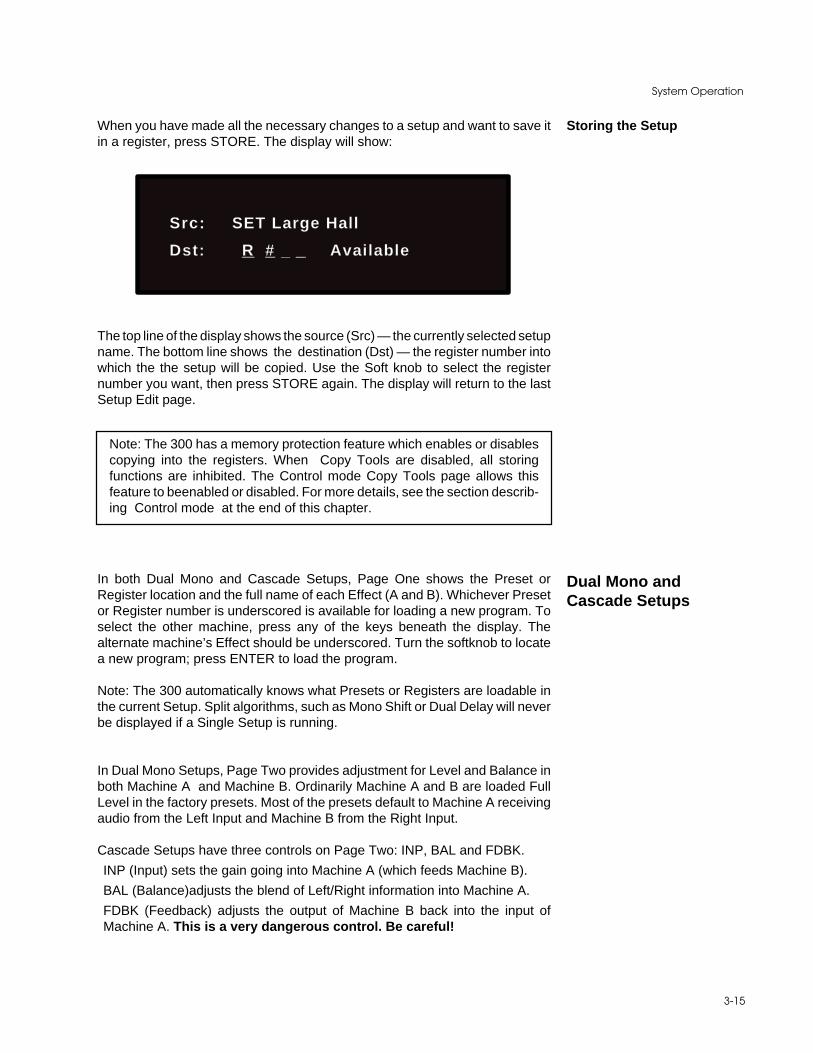
Storing the SetupWhen you have made all the necessary changes to a setup and want to save itin a register, press STORE. The display will show:
Src: SET Large Hall
Dst: R # _ _ Available
The top line of the display shows the source (Src) — the currently selected setupname. The bottom line shows the destination (Dst) — the register number intowhich the the setup will be copied. Use the Soft knob to select the registernumber you want, then press STORE again. The display will return to the lastSetup Edit page.
Note: The 300 has a memory protection feature which enables or disablescopying into the registers. When Copy Tools are disabled, all storingfunctions are inhibited. The Control mode Copy Tools page allows thisfeature to beenabled or disabled. For more details, see the section describ-ing Control mode at the end of this chapter.
In both Dual Mono and Cascade Setups, Page One shows the Preset orRegister location and the full name of each Effect (A and B). Whichever Presetor Register number is underscored is available for loading a new program. Toselect the other machine, press any of the keys beneath the display. Thealternate machine’s Effect should be underscored. Turn the softknob to locatea new program; press ENTER to load the program.
Note: The 300 automatically knows what Presets or Registers are loadable inthe current Setup. Split algorithms, such as Mono Shift or Dual Delay will neverbe displayed if a Single Setup is running.
In Dual Mono Setups, Page Two provides adjustment for Level and Balance inboth Machine A and Machine B. Ordinarily Machine A and B are loaded FullLevel in the factory presets. Most of the presets default to Machine A receivingaudio from the Left Input and Machine B from the Right Input.
Cascade Setups have three controls on Page Two: INP, BAL and FDBK.
INP (Input) sets the gain going into Machine A (which feeds Machine B).
BAL (Balance)adjusts the blend of Left/Right information into Machine A.
FDBK (Feedback) adjusts the output of Machine B back into the input ofMachine A. This is a very dangerous control. Be careful!
Dual Mono andCascade Setups
Lexicon300 V 3.0 Owner's Manual
3-16
Dual Mono Setups provide two Mix controls on Page Three: AMIX and BMIX.These are independent mix controls for each machine.
Cascade Setups provide three Mix controls on Page Three: AMIX, BMIX andOMIX.
AMIX varies the amount of “dry” input in Machine A’s wet output. This Mixtureof wet and dry (if any) is passed along to the input of Machine B.
BMIX adjusts the proportion of Machine A’s wet output to the “wet” output ofMachine B.
OMIX takes that mix result and mixes it with the “Dry” input signal.
The LFO (Low Frequency Oscillator) is a control generator which is designed tomodulate Effect or Setup parameters in the 300 when parameters are patchedto it. The LFO has a shape and a rate (speed) function, available on Page Four.The shape can be SINEusoidal, TRIANGLE, SQUARE, or RANDOM. Rate isadjustable from Off to 9.0Hz.
The action of the meters (FX-OUT for either Left or Right channel) is determinedon Page Five.
Note: If you choose Left Meter or Right Meter as Patch sources when makingMOD Edits, you are essentially linking the ballistics of the meter to the destinationparameter.
Pages Six and Seven allow you to make as many as two MOD patches in theSetup domain.
On Page Eight you can name your Setup prior to storing it into a register. Thearrow (cursor) keys allow you to select a letter to change; the softknob actuallychanges the character. The maximum length of a name is 12 characters.
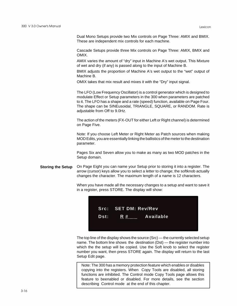
When you have made all the necessary changes to a setup and want to save itin a register, press STORE. The display will show:
Storing the Setup
Src: SET DM: Rev/Rev
Dst: R # _ _ Available
The top line of the display shows the source (Src) — the currently selected setupname. The bottom line shows the destination (Dst) — the register number intowhich the the setup will be copied. Use the Soft knob to select the registernumber you want, then press STORE again. The display will return to the lastSetup Edit page.
Note: The 300 has a memory protection feature which enables or disablescopying into the registers. When Copy Tools are disabled, all storingfunctions are inhibited. The Control mode Copy Tools page allows thisfeature to beenabled or disabled. For more details, see the sectiondescribing Control mode at the end of this chapter.

3-17
System Operation
Page Five
INS DEL ← ← → →
Current Setup Name
The bottom line of the display shows the name of the current setup, with a cursorpositioned under the first character. The two keys directly above the left and rightarrows cause the cursor to move left and right to select other characters.
Pressing the key directly above "INS" adds a blank space wherever the cursoris currently positioned in the display. Pressing the key directly above "DEL"removes the underscored character.
Turning the soft knob alters the underscored character. (Available charactersinclude: 0-9, a-z, A-Z, and an assortment of symbols.)
To rename the setup, simply position the cursor under the first character of thecurrent name, turn the softknob to replace this character with the first characterof the name you want, select the next character and change it, etc.
When you have made all the necessary changes to a setup and want to save itin a register, press STORE. The display will show:
The top line of the display shows the source (Src) — the currently selected setupname. The bottom line shows the destination (Dst) — the register number intowhich the the setup will be copied. Use the Soft knob to select the registernumber you want, then press STORE again. The display will return to the lastSetup Edit page.
Naming the Setup
Storing the Setup
Src: SET Large Hall
Dst: R# Available
Note: The 300 has a memory protection feature which enables or disablescopying into the registers. When Copy Tools are disabled, all storingfunctions are inhibited. The Control mode Copy Tools page allows thisfeature to beenabled or disabled. For more details, see the sectiondescribing Control mode at the end of this chapter.

Lexicon300 V 3.0 Owner's Manual
3-18
The 300 is shipped with 100 effect presets. Sooner or later you will want to alterthe sounds of these effects to more perfectly fit your requirements. To do this,goto Run mode and load a preset setup that uses the effect you want to edit — orselect and load the effect you want to edit from Page One in Setup Edit mode.Once the setup is loaded, pressing EFFECT EDIT will put you in Effect Editmode with the display showing one page of the parameters available for thealgorithm driving that effect.
The algorithms and their parameters are described in detail in Chapter 4. We'vechosen the first page of Random Hall parameters to show here as an example:
RTIM SIZE ROLL PDLY
RLVL TDCY BASS XOVR
The buttons directly above and below each display entry will select thatparameter. Once selected, parameters can be adjusted over their entire rangewith the Soft knob. The parameter and its current value will appear on the displayas long as the Sof tknob is being adjusted. In the example above, "RTIM" hasbeen selected — turning the Soft knob will alter the parameter value, and causethe display to show:
Pressing the front panel VALUE key will display all of the current parametervalues for the selected page. in this example, pressing VALUE will cause thefollowing display to appear:
Effect Edit Mode
Parameter Selection
CONTROLSETUP
SELECT
MACH
STORE
VALUE
SETUP
EDIT
EFFECT
EDIT
MOD
EDIT
Mid Reverb Time
XX.XX seconds
XX.Xs 37.1M 2.9k 22m
FULL 3.6k 1.2X 0.5k
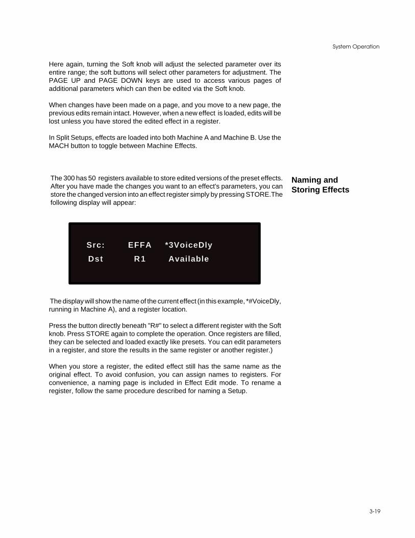
3-19
System Operation
Here again, turning the Soft knob will adjust the selected parameter over itsentire range; the soft buttons will select other parameters for adjustment. ThePAGE UP and PAGE DOWN keys are used to access various pages ofadditional parameters which can then be edited via the Soft knob.
When changes have been made on a page, and you move to a new page, theprevious edits remain intact. However, when a new effect is loaded, edits will belost unless you have stored the edited effect in a register.
In Split Setups, effects are loaded into both Machine A and Machine B. Use theMACH button to toggle between Machine Effects.
The 300 has 50 registers available to store edited versions of the preset effects.After you have made the changes you want to an effect's parameters, you canstore the changed version into an effect register simply by pressing STORE.Thefollowing display will appear:
Naming andStoring Effects
Src: EFFA *3VoiceDly
Dst R1 Available
The display will show the name of the current effect (in this example, *#VoiceDly,running in Machine A), and a register location.
Press the button directly beneath "R#" to select a different register with the Softknob. Press STORE again to complete the operation. Once registers are filled,they can be selected and loaded exactly like presets. You can edit parametersin a register, and store the results in the same register or another register.)
When you store a register, the edited effect still has the same name as theoriginal effect. To avoid confusion, you can assign names to registers. Forconvenience, a naming page is included in Effect Edit mode. To rename aregister, follow the same procedure described for naming a Setup.

Lexicon300 V 3.0 Owner's Manual
3-20
Mod Edit mode is used to create or modify Dynamic MIDI® patches. To useDynamic MIDI®, you assign a MIDI controller or an event to a setup parameteror an effect parameter, using the patch parameters found on the pages in ModEdit. (Two pages for Setup patches are available in Setup Edit mode.) Fourparameter patch pages are available at any one time in Mod Edit mode. Thepages will be for Machine A or Machine B, depending on the type of setupcurrently running, and on the machine currently selected.
Each of the four available patch pages shows the following parameters:
Patch # 1A DEST VALUE
SOURCE THRS SCALE
Destination: This is used to select the effect parameter that the MIDI controlleris patched to. The available parameters are based on the algorithm that you arecurrently running.
Value: This is used to set the initial value of the parameter that you arecontrolling. This is provided as a convenience so that you do not have to go intoEffect Edit mode to view the available parameters of the running algorithm.
Source: This is used to select the MIDI controller, or event, that will control aneffect parameter in the 300. The list contains the selections shown to the left.
Threshold: This is used to set thecontroller value below which the controller willnot have an effect on the parameter.
Scale: This is used to set the effective control range of the MIDI controller.Scaling can be set from -200% to +200%. When Scale is set to 100%, the fullrange of the MIDI controller will cover the full range of the selected parameter.Setting a negative value will cause the 300 to reduce the setting of the parameteras the controller increases.
You can store any patches you create with the Effect simply by pressing STORE,selecting a register number with the Soft knob, and then pressing STORE again.
Note: Be extremely careful when creating patches while a MIDI deviceis connected. If you accidentally send a MIDI Program Change beforesaving the patches in a register, they will be lost. To avoid thispossibility, you may want to set the MIDI Master Channel (in ControlMode) to OFF, or unplug the MIDI cable from the 300's rear-panel MIDIIN connector.
Mod Edit Mode
OffCntlr- 0
ModWheelBreathCntlr-3
FootPedalPortaTime
VolumeCntlr-9
PanExpressionCntlr-12-15
GP Cntlr-1-4Cntlr-20-31
SustainPortaSw
SostenSwSoftPedal
Switch-68-79GP Cntlr-5-8Sitch-84-95PitchWheelAfterTouchLastNoteLastVel
MidiClockKnob->L-MeterR-MeterLFO-1
Available "Source" selections
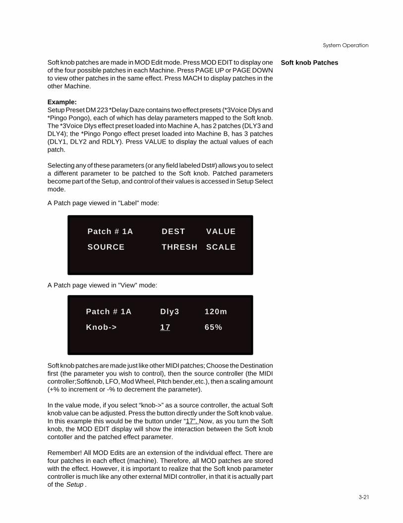
3-21
System Operation
Soft knob patches are made in MOD Edit mode. Press MOD EDIT to display oneof the four possible patches in each Machine. Press PAGE UP or PAGE DOWNto view other patches in the same effect. Press MACH to display patches in theother Machine.
Example:Setup Preset DM 223 *Delay Daze contains two effect presets (*3Voice Dlys and*Pingo Pongo), each of which has delay parameters mapped to the Soft knob.The *3Voice Dlys effect preset loaded into Machine A, has 2 patches (DLY3 andDLY4); the *Pingo Pongo effect preset loaded into Machine B, has 3 patches(DLY1, DLY2 and RDLY). Press VALUE to display the actual values of eachpatch.
Selecting any of these parameters (or any field labeled Dst#) allows you to selecta different parameter to be patched to the Soft knob. Patched parametersbecome part of the Setup, and control of their values is accessed in Setup Selectmode.
Soft knob Patches
A Patch page viewed in "Label" mode:
Patch # 1A DEST VALUE
SOURCE THRESH SCALE
A Patch page viewed in "View" mode:
Patch # 1A Dly3 120m
Knob-> 17 65%
Soft knob patches are made just like other MIDI patches; Choose the Destinationfirst (the parameter you wish to control), then the source controller (the MIDIcontroller;Softknob, LFO, Mod Wheel, Pitch bender,etc.), then a scaling amount(+% to increment or -% to decrement the parameter).
In the value mode, if you select “knob->” as a source controller, the actual Softknob value can be adjusted. Press the button directly under the Soft knob value.In this example this would be the button under “17”. Now, as you turn the Softknob, the MOD EDIT display will show the interaction between the Soft knobcontoller and the patched effect parameter.
Remember! All MOD Edits are an extension of the individual effect. There arefour patches in each effect (machine). Therefore, all MOD patches are storedwith the effect. However, it is important to realize that the Soft knob parametercontroller is much like any other external MIDI controller, in that it is actually partof the Setup .

Lexicon300 V 3.0 Owner's Manual
3-22
If the Soft knob value is set to 37, and then stored into a Setup Register, whenyou recall that Setup, the knob will automatically set the effect parameter valuewhich it controls.
It is also important to understand that, if you load a Setup which has a Soft knobvalue of say, 66, and then load any other effect(s) into that setup, any Soft knobpatches which exist in the newly loaded effect(s) will cause the linked parame-ters to jump to some new value. The Soft knob value controls the linkedparameter(s) at all times.
Control Mode
Event List: OFF VIEW
ADD DEL EDIT SNAP
Control mode provides access to general global parameters and miscellaneousfunctions including audio configuration. Selecting Control mode does notinterrupt the audio operation of the 300.
There are nine Control mode pages:Event ListMIDI Mode and Map TableMachine ConfigurationDigital Interface and Sampling RatesSCMS ModeEmphasisBypass/Effect Load ModeCopy ToolsPurge Tools
Each of these pages is described below.
This page allows creation and modification of a list of up to 50 events triggeredstandard timecode or MIDI timecode. Four main functions are provided: Add,Delete, Edit and Snap. (For more information, see Chapter 6: Time CodeOperation.
Page OneTime Code Event List

3-23
System Operation
The MIDI Control page allows you to specify mapping of MIDI Non-registeredparameters, System Exclusive messages or Program Change messages to the300 registers. The button directly above "AUTO" allows you to set this MIDIMode.
Page TwoMIDI Mode and Map Table
On the upper line, selecting "AUTO" activates output automation on the 300. Thechoices are OFF, SysEx, Non-registered parameters, and Program ChangeOnly. When the AUTO Mode is set to "OFF", the 300 will not output MIDI data.
Note: In "Program Change Only" automation mode, effect registers R29-50 arenot transmitted as their sequence numbers fall outside of the range of what canbe legally represented by a MIDI data byte (0x00-0x7F). Therefore:
program change # 0x00-0x63 = E: P1-100program change # 0x64-0x7F = E: R1-28
(For more information on Automation, see MIDI Operation.)
Selecting "CHNL" allows you to set the system and machine channels on whichthe 300 can send and receive messages. Possible setttings are: 1-16, OMNI. Allbulk dump and SysEx messages, except Program Change, follow the systemchannel, while all generic MIDI and Non-registered parameter messages followthe machine channel assignment.
Selecting "EDIT" allows you to speciy the MIDI mapping mode. The threechoices available are: OFF, FIX or MAP. For complete information on the MIDITable, see Chapter 7: MIDI Operation.
Selecting "DUMP" allows you to dump all registers, the current setup, the MIDIMap Table, or a MIDI Timecode Event List.
MIDI Mode: AUTO CHNL
P Chg Map: EDIT DUMP

Lexicon300 V 3.0 Owner's Manual
3-24
Page ThreeMachine Configuration
Mach Conf: Dual-Mono
I : ANALOG O : ANA+DIG
Page FourDigital Interface and
Sampling RatesInp: * * * * * Clk : 48kHz
Out: AES Din : XLR
This upper line of this page describes the current format being input to the 300.When no digital signal is present, the display will show "* * * * *" as above.
If the incoming audio signal is analog, selecting "Clk" allows Soft knob selectionof the system sample rate for analog operation: 48kHz or 44.1kHz. (Theappropriate sample rate LEDs on the left side of the display will illuminate toindicate the sample rate selected.) If the input is digital, the system willautomatically lock to the sample rate of the incoming data and display "Lock."Otherwise, "***" will be displayed to indicate that the incoming digital signal hasnot yet been detected.
Either of the two left buttons on the botton allow selection of AES or SPDIF asoutput format.
The two right buttons on the bottom row allow you to specify the connector usedfor audio input: XLR, RCA, or OPT.
The upper line of this page describes the current machine configuration (Single,Dual Mono or Cascade). The information that appears here is determined by thetype of Setup currently running.
Either of the two left buttons on the botton allow selection of Input: ANALOG andDIGITAL are available as choices with all types of setups. A>L D>R (Analog/Left, Digital/Right), or D>L A>R (Digital/Left, Analog/Right) is available forselection in Dual Mono setups..
The two right buttons on the bottom row allow selection of Output: ANA+DIG isavailable in all setup types. A(D Pre), or A(D Pst) and D(A Pre), or D(A Pst) areavailable in Dual Mono setups. Cascade setups display choice between A(DPre, Mid or Pst) and D(A Pre, Mid or Pst) for patch point selection.

3-25
System Operation
This page provides control over the SCMS (Serial Copy Management System)bits embedded in certain digital audio formats. The upper line of this pagedescribes the SCMS status of your input source.
Either of the two right buttons on the botton allow Soft knob selection of theSCMS setting which will be output by the 300. The choices are: NO COPY, ONECOPY and MULT-COPY.
Page FiveSCMS Mode
SCMS Inp: XX
SCMS Out: MULT-COPY
Page SixEmphasis
Emph Inp: D>N A>N
Emph Out: D>N A>N
The top line (I) displays the input status of the incoming digital audio signal. (*****if none detected). The bottom line (O) shows your selections for the output datastream.
The soft buttons act as toggle switches for the selections on this page. The Softknob can also be used to alter selected items.
"D>N" on the top line shows the Incoming pre-emphasis bit status (in thisexample "N"). Pressing the key directly below "D>N" sets the bit's outgoingstatus, Y(on) or N(off).
The rightmost buttons on both the top and bottom row select analog pre- and de-emphasis. The choices are: Y (on) or N (off). Control of emphasis/de-emphasislinks the input and output, i.e. you can select both or neither.

Lexicon300 V 3.0 Owner's Manual
3-26
Page SevenBypass/Effect Load Mode
The Copy Tools page allows you to copy setups, effects, or the mod portion ofeffects into the registers. This page also allows you to enable and disable the300's memory protection function. When you call up the Copy Tools page, thedisplay will show:
Page EightCopy Tools
Copy Tools: ENABLE
SETUP EFX MIDI
The upper line on this page allows you to enable, or prohibit, the 300's copyfunctions. Pressing either of the two righthand buttons above the display willtoggle the memory protect function between "ENABLE" and "DISABLE". Dis-abling the memory function will prevent: Event List and MIDI Map editing, Setupand Effect storing, Setup and Effect copying, as well as incoming MIDI loads ofany of the above.
The lower line allows selection of: "SETUP", "EFX", or "MIDI". Selecting"SETUP" will cause the display to show:
If you change between setups which use different algorithms, the system willeither mute or bypass while the parameter changes are being made, dependingon the selection you make here under "Effect Load".
Selecting "MUTE" will mute the analog and digital outputs during thesetransitions; selecting "BYPASS" allows you to hear the unprocessed audiosignal.
This page also allows you to select whether the front panel BYPASS buttonsmute the incoming signal (INMUTE) or bypass processing (BYPASS).
Effect Load: MUTE
Bypass Btns: INMUTE

3-27
System Operation
Select "Src" and use the Soft knob to designate a setup number (or the currentsetup) to be copied; select "Dst" and use the Soft knob to specify the registernumber where you want this copy stored. When you have made these selec-tions, press STORE.
Selecting "EFX" will cause a similar page to appear which allows you to copy theeffect and the patches used in any effect to any other register.
Selecting "MIDI" allows you to copy patches from one effect to another.
Page NinePurge Tools
The Purge page allows you to delete all setup or effect registers, the MIDIProgram Change Map Table, or the Time Code Event List. It also allowsreinitialization of a Lexicon demonstration (erasing all user effects and TimeCode Event List data), and a complete reinitialization of the system to its factoryconfiguration.
Purge Tools: FACTORY
SETUP EFX MIDI TCODE
Select "TCODE" to clearthe Time Code Event List.
Select "SETUP" to clear allsetup registers. Select "EFX" to clear all ef-
fect registers.
Selecting "FACTORY" restores the 300 to its factory memoryconfiguration. This selection will destroy all user modifica-tions of the original factory configurations.
Select "MIDI" to clear theMIDI Program ChangeMap Table.
Pressing any of the active buttons to select one of these options will cause thedisplay of a warning prompt. When this prompt appears, press STORE toexecute the function.
Be careful! These functions permanently erase user information.
Src : SET Large Hall
Dst: R # _ _ Available

4-1
The Algorithms and their Parameters
4The Algorithmsand theirParameters
Lexicon300 V 3.0 Owner's Manual
4-2
The 300 incorporates the results of a great deal of research into acoustics andreverberation. Reverberation, or reflected sound energy, gives recorded musica sense of being performed in a real acoustic location.
In the 300, the SIZE, SPREAD and SHAPE controls allow adjustment of thebuildup and decay of the initial part of the reverberation envelope. SHAPEcontrols the shape of the envelope, while SPREAD and SIZE set the time overwhich this shape is active.
In the Random Hall program, SIZE acts as a master control for the apparent sizeof the space being created by the 300. Both SPREAD and RTIM vary linearlywith the setting of SIZE. Thus maximum reverb time and spread require highsettings of SIZE. To find an appropriate reverb sound, start with a preset with asimilar sound to what you want to end up with. Simply varying SIZE is oftensufficient to arrive at the exact sound you are seeking.
Once a size has been selected, SPREAD and SHAPE are used to adjust theshape and duration of the initial reverb envelope, which together provide themajor sonic impression of room size.
When SHAPE is at minimum, the reverberation envelope builds up very quicklyto a maximum amplitude, and then dies away quickly at a smooth rate. Thisenvelope is characteristic of small reverberation chambers and reverberationplates. There are few (if any) size cues in this envelope, so it is ineffective increating ambience. With this SHAPE setting, SPREAD has no effect. Thedensity is set by the size control, and the rate of decay is set by RTIM. Thisreverberation envelope is typical of many of the popular digital reverberators ofthe last few years.
As SHAPE is raised to about 1/8 of its range, the initial sharp attack of thereverberation is reduced, and reverberation builds more slowly. The envelopethen sustains briefly before it begins to die away at the rate set by RTIM.SPREAD has little or no effect on this shape.
When SHAPE is at 1/4 of its range, buildup is even slower and the sustain islonger. Now SPREAD affects the length of both the buildup and the sustain. Asa rough estimate, the sustain will be approximately the time value indicated bythe SPREAD display (in milliseconds).
As SHAPE is raised further, the buildup and sustain remain similar, but now asecondary sustain appears in the envelope, at a lower level than the first. Thissecondary plateau simulates a very diffused reflection off the back wall of a hall,and is effective in creating a sense of size and space. This reflection becomesstronger and stronger, reaching an optimal loudness when SHAPE is at about1/2 of its range.
The highest SHAPE settings are typically used for effects. Near the top of thescale the back wall reflection becomes stronger than the earlier part of theenvelope, resulting in an inverse sound.
General Description
Single SetupAlgorithms
Random Hall

4-3
The Algorithms and their Parameters
Note that none of these shape effects are audible unless RTIM is set shortenough. Generally, RTIM should be set to a value of about 1.2 seconds for smallrooms, and up to 2.4 seconds or so for halls. SIZE should also be set to a valueappropriate to the desired hall size (note, however, that small sizes color thereverberation).15 meters makes a very small room, and 38 meters is useful fora large hall.
Used with care SHAPE and SPREAD allow the 300 to produce superiorambience—a sound which is spacious and has great depth—without the longreverberation of a church.
The Random Hall algorithm in the 300 incorporates random delay elements.These elements have several effects. First, there is a reduction of long-livedmodes in the reverberant decay, which makes the decay less metallic andreduces the apparent reverb time. The random elements also improve thesteady-state timbre of the program.
The speed at which the delay elements move is controlled by SPIN. Values ofSPIN which are higher than about 38 can cause audible pitch wobble in verycritical material (such as classical guitar or piano and can also cause noise onpure tones. This noise is not audible in speech, however, and, for mixed musicor speech, values up to 48 will give an improved sound. WANDER is typically setto about 10ms at larger settings of SIZE. The effect of WANDER is reduced forsmall SIZEs.
When you set out to create a sound, the first and most important decision is howbig a space you want. The best way to start is to listen to several presets andchoose the one which sounds closest to what you have in mind. If necessary, useSIZE to make a slightly larger or smaller sound, as needed.
Next use RTIM to fine-tune the amount of time the reverberation takes to dieaway at the end of musical phrases. Actual halls vary a great deal in their actualRTIM values. The setting of the BASS is also critical in matching the sound ofan existing hall. An ideal concert hall would have a BASS setting of 1.2. It is rarewhen actual physical spaces exceed 1.5. Many (if not most) good recordingenvironments have values of BASS of 1.0 or less, so a value of 0.8 could be triedwhen attempting to match an existing hall.
There are two additional controls to deal with. SHAPE and SPREAD adjust theeffective reverb time when the music is running. Higher values of SHAPE andSPREAD produce a longer effective reverb time. Longer effective reverb timesgive greater spaciousness to the sound.
The 300 reverberation algorithm offers the option of adding early reflections (pre-echoes) which have been made into diffused clusters of pre-echoes. The densityof the cluster is set by the DIFFUSION control. We recommend that these pre-echoes be used with caution, unless you are trying to match the sound of thereverberation to a particular location where such reflections are strong.
Creating a Realistic Sound
Random Delays

Lexicon300 V 3.0 Owner's Manual
4-4
Random Hall Basic Sounds
RTIM SIZE ROLL PDLY.02-60.49s 4-39.4M 0.1-26.5kHz, Flat 0-1000ms
RLVL TDCY BASS XOVROff-48dB-Up Full 0.5-21.2kHz 0.2x-4.0x 0.1-26.5kHz
Random Hall Tweaks
SPIN WAND SHAP SPRD0-48 0µs-37.1ms 0-255 0-250DIFF LINK SHLF SIZE0-99 Link/Unlink Off-24dB-Up Full 4-39.4M
Random Hall Pre-Echoes
DLY1 DLY2 RTIM -0-1000ms 0-1000ms .24-65.39s -
LVL1 LVL2 RLVL -Off-24dB-Up Full Off-24dB-Up Full Off-24dB-Up Full -
Feedback Pre-Echoes
DLY3 FBK3 DLY4 FBK40-2800ms -93 to +93% 0-2800ms -93 to +93%
LVL3 LVL4Off-24dB-Up Full Off-24dB-Up Full
Effect Naming Page
Random HallParameters
Random Hall Basic Sounds Page
RTIM (Mid-FrequencyReverb Time)
RTIM sets the reverb time for mid-frequency signals. Because low-frequencyreverb time (BASS) is a multiplier of RTIM, RTIM acts as a master control for thereverb time.
SIZE sets the rate of buildup of diffusion after the initial period (which iscontrolled by DIFF). It also acts as a master control for RTIM and SPRD. TheSIZE control changes a reverb sound from very large to very small. Generally,
SIZE
Diffusion Predelay R Level
Reverberator
RTIME SIZE SHAPE SPREAD
XOVR BASS TDCY LINK
SPIN
Delay 1
Σ
Fbk 3
Delay 3 Level 3
Level 1 Σ
Delay 2
Σ
Level 2 Σ
Fbk 4
Level 4Delay 4
WANDER
Rolloff
SHLF

4-5
The Algorithms and their Parameters
you should set the SIZE control to approximate the size of the acoustic space youare trying to create, before adjusting anything else. The size in meters is roughlyequal to the longest dimension of the space. Moving SIZE while a signal ispresent may cause audible transients on critical material.
The apparent size of the space created is actually a combination of the settingsof the SIZE, SHAP, and SPRD controls. Small acoustic spaces are character-ized by a rapid buildup of diffusion. However, both small and large spacesfrequently have an uneven buildup of initial reverberation. This uneven buildupis controlled by the SPRD and SHAP controls.
ROLL sets the frequency above which a 6 dB/octave low-pass filter attenuatesthe processed signal. It attenuates both pre-echoes and reverberant sound.High frequencies are often rolled off with this parameter, resulting in more naturalsounding reverberation. The low-pass characteristic can be modified to ashelving charactistic with the SHLF control. When SHLF is off, ROLL is typicallyset betwen 2kHz and 4kHz.
PDLY adjusts an additional time delay between the input of signal and the onsetof reverberation. The control is not intended to mimic the time delays in naturalspaces. In real rooms the build-up of reverberation is gradual, and the initial timegap is usually relatively short. Natural spaces are best emulated by setting SHAPat a middle value and adjusting SPRD for the desired effective pre-delay.
Additional delay added with the PDLY control can increase the initial time gapslightly, emulating a situation where reverberant pick-up microphones arelocated much further from the source than the main microphones. If less thanabout 30ms of pre-delay is added, this additional delay can add clarity with somemusic, but it can also sound unnatural. Large pre-delays can be useful for slap-echo effects.
RLVL sets the amount of reverberation in the processed signal. It is normallyFULL, but may be reduced for effects where the pre-echoes should dominate.
TDCY sets the frequency above which sounds decay at a progressively fasterrate. It filters all the sound except the pre-echoes. When set relatively low, it givesa darker tone to the reverberation, simulating the effect of air absorption in a realhall. TDCY also helps keep the ambience generated by the program frommuddying the direct sound.
BASS sets the reverb time for low-frequency signals, as a multiplier of the RTIMparameter. For example, if BASS is set to 2X, and RTIM is set to two seconds,the low frequency reverb time will be four seconds. For a natural-sounding hallambience, we recommend values of 1.5X or less.
XOVR sets the frequency at which the transition from RTIM to BASS takes place.XOVR should be set at least two octaves higher than the low frequency you wantto boost. For example, to boost a signal at 100 Hz, set XOVR to 400 Hz (Thissetting works well for classical music). XOVR works best around 400 for boostinglow frequencies, and around 1.5 kHz for cutting low frequencies.
ROLL (Hi Freq Rolloff)
PDLY (Pre-Delay)
RLVL (Reverb Level)
TDCY (Treble Decay)
BASS (Bass Multiply)
XOVR (Bass Crossover)

Lexicon300 V 3.0 Owner's Manual
4-6
Random Hall Tweaks Page
SPIN affects the movement of the reverberation tail. The object of SPIN (andWAND) is to continuously alter the timbre of the reverberant sound. This makesthe result more natural, without making the position of instruments unstable.SPIN should typically be 20 or higher. High values may make the pitch of pianoor guitar unstable.
WAND sets the distance in time that the early reflections will move. For bestresults WAND should be about 10ms at larger sizes.
SHAP and SPRD work together to control the overall ambience of the reverbera-tion created by the 300. SHAP determines the contour of the reverberationenvelope. With SHAP all the way down, reverberation builds explosively, anddecays quickly.
As SHAP is advanced, reverberation builds up more slowly and sustains for thetime set by SPRD. With SHAP in the middle, the buildup and sustain of thereverberation envelope emulates a large concert hall (assuming that SPRD is atleast halfway up, and that SIZE is suitably large—30 meters or larger.)
SPRD works together with SHAP to control the duration of the initial ambiencecreated by the 300. Low SPRD settings result in a rapid onset of reverberationat the beginning of the envelope, with little or no sustain. Higher settings spreadout both the buildup and sustain.
DIFF controls the degree to which initial echo density increases over time. Highsettings of DIFF result in high initial buildup of echo density, and low settingscause low initial buildup. Echo density is also affected by SIZE; smaller spaceswill sound denser. To enhance percussion, use high settings of diffusion. Forclearer and more natural vocals, mixes, and piano music, use low or moderatesettings of diffusion.
When LINK is set, the reverb time and spread values scale linearly as the SIZEcontrol is varied. For some special effects, RTIM and SPRD can be unlinked.
SHLF modifies the low-pass characteristic of the rolloff control, turning it into ashelving filter. SHLF sets the gain of an output path which is mixed with the outputof ROLL to form the main reverberant output. Both the pre-echoes and thereverberation are affected. For example, if SHLF is set to -6dB, frequenciesbelow approximately ROLL/2 will be boosted by 3.5dB; above approximatelyROLL x 2, the response will be flat.
SHLF provides a method for making the spectral content of the reverberationmatch the ideal spectrum for musical acoustics in rooms. For this application,ROLL should be set between 700 and 1.5kHz, with SHLF set between 12 and-6dB.
SPIN (Randomization)
WAND (Wander)
DIFF (Diffusion)
SHAP (Shape)
SPRD (Spread)
LINK
SHLF

4-7
The Algorithms and their Parameters
SIZE sets the rate of buildup of diffusion after the initial period (which is controlledby DIFF). It also acts as a master control for RTIM and SPRD. The SIZE controlchanges a reverb sound from very large to very small. Generally, you should setthe SIZE control to approximate the size of the acoustic space you are trying tocreate, before adjusting anything else. The size in meters is roughly equal to thelongest dimension of the space. Moving SIZE while a signal is present maycause audible transients on critical material.
The apparent size of the space created is actually a combination of the settingsof the SIZE, SHAP, and SPRD controls. Small acoustic spaces are character-ized by a rapid buildup of diffusion. However, both small and large spacesfrequently have an uneven buildup of initial reverberation. This uneven buildupis controlled by the SPRD and SHAP controls.
Random Hall and Feedback Pre-Echoes Pages
The Random Hall Pre-Echoes page and the Feedback Pre-Echoes page containfour pre-echo taps with delay and level controls. The taps are fed directly to theoutput wet signal rather than into the reverberator.
Pre-echoes can best be understood by visualizing a stage where the earlyreflections are the sounds emanating from the rear and side stage walls directlyafter the sound from the stage. Usually the rear stage wall reflection is earlier andlouder than those from the two side walls. The pre-echoes are actually clustersof echoes, with the density of the cluster set by DIFF.
The pre-echo delay parameters change the perceived locations of reflectingsurfaces surrounding the source. Level adjusts the loudness of the reflection.For each of the Lvl (Pre-echo level) parameters, there is a corresponding Dlyparameter. Each of these sets the delay time in ms for one of the pre-echoes.These are not affected by PDLY, so pre-echoes can be placed to occur beforethe reverberation starts.
The Dly pre-echo delay parameters have a resolution of 2 milliseconds.
The Lvl pre-echo level parameters have sixteen steps, calibrated in decibels.
The Fbk feedback parameters (for Delays 3 and 4 only) are adjustable in 6%increments from -93% to +93%.
Pre-Echo 1, one second maximum to left channel.
Pre-Echo 2, one second maximum to right channel.
Pre-Echo 3, 2.8 seconds maximum to left channel, with feedback.
Pre-Echo 4, 2.8 seconds maximum to right channel, with feedback.
SIZE
DLY1, LVL1
DLY2, LVL2
DLY3, LVL3, FBKk3
DLY4, LVL4, FBK4

Lexicon300 V 3.0 Owner's Manual
4-8
Random Ambience
General Description The 300's Random Hall effects are designed to add a cushion of reverberanceto recorded music, while leaving the clarity of the direct sound unaffected.Random Ambience is different. It is intended to become a part of the direct sound— to give it both better blend and a definite position in space. Random Ambiencegives warmth, spaciousness and depth to a performance without coloring thedirect sound at all.
Random Ambience generates primarily the strong reflections which appear inthe first few hundred milliseconds of the reverberation process. These earlyreflections constitute the primary audible effect, giving you the impression of ahall surrounding you while the music is playing. To avoid any coloration fromthese strong reflections, the time delays and amplitudes are random functions.
Random Ambience is very useful for adding a room sound to recorded music orspeech. It is particularly easy to match a studio recording of dialog to a typicalroom environment. In music recording, using Random Ambience is an effectiveway of realistically adding distance to a close-miked signal. If an ensemble hasbeen recorded with close-mikes and pan pots, Ambience can provide themissing blend and depth. The apparent position of the instruments is preservedin the reverb while the apparent distance is increased. Random Ambience isalso useful in matching a closely miked accent microphone to the overallambience of a recording. This allows a soloist to be increased in level withoutchanging the apparent distance. Random Ambience can be used in a recordingsituation any time a close-miked sound is undesireable.
Set the SIZE to the desired room size. RLVL adjusts the amplitude of reverbera-tion defined by RTIM, and can be trimmed to get exactly the effect you need.
To use the algorithm with a console, it is best to use a stereo send to the 300,carefully matching the panning of the various close-miked sources to theirpositions in the mix. Leave the MIX control at 100%. The apparent distance ofeach source can be controlled by the level of its feed.

4-9
The Algorithms and their Parameters
Random Ambience Basic Sounds
RTIM SIZE DIFF ROLL0.18-47.82s 4.0-39.4M 0-99 0.5kHz-21.2kHz
RLVL DDLY PDLY -Off, -48to-1dB, Up Full 0-99.9ms 0-99.9ms -
Random Ambience Tweaks
SPIN WAND - -0-48 0-37.1ms - -
- - - -- - - -
Effect Naming Page
Random AmbienceParameters
Random Ambience Basic Sounds Page
This control adjusts the reverberation time of the independent reverberator. Therange of action is limited. Be careful — both long and short reverb times maysound unnatural. If a much longer or shorter reverb time than the preset providesis desired, SIZE should be changed first.
SIZE allows you to vary the apparent size of the space over a wide range. SIZEis the most dramatic control, and must be selected to match the music or programmaterial. It should be the first control that you adjust to tailor the desired space.SIZE also affects the reverb time, in a similar way to the standard reverbprograms.
DIFF controls the degree to which initial echo density increases over time. Highsettings of DIFF result in high initial buildup of echo density; low settings causelow initial buildup. Echo density is also affected by SIZE; smaller spaces willsound denser. To enhance percussion, use high settings of DIFF. For clearer,more natural vocals, mixes, and music, use low or moderate settings.
ROLL sets the frequency above which a 6 dB/octave low-pass filter attenuatesthe processed signal. It attenuates both pre-echoes and reverberant sound.High frequencies are often rolled off with this parameter, resulting in more naturalsounding reverberation.
LR
D Delay
ΣΣ
Ambience Generator
Diffusion Predelay
D Delay
SIZE RTIME RLVL
SPIN WANDERRolloff
RTIM (Reverb Time)
SIZE
DIFF
ROLL (Hi Freq Rolloff)

Lexicon300 V 3.0 Owner's Manual
4-10
RLVL sets the amount of reverberation in the processed signal. It is normallyFULL, but may be reduced for effects where the pre-echoes should dominate.
DDLY provides a delay for the "dry" audio path.
PDLY adds an additional delay to the reflections and to the reverberation. Thiscontrol may be useful in a sound reinforcement situation, or for ambience effects.Both DDLY and PDLY have 4-sample (approximately 0.1msec) resolution.
Random Ambience Tweaks Page
SPIN affects the movement of many of the delay taps. The object of SPIN (andWAND) is to continuously alter the timbre of the reverberant sound. This makesthe result more natural, without making the position of instruments unstable.SPIN should typically be 20 or higher. High values may make the pitch of pianoor guitar unstable.
WAND sets the distance in time that the early reflections will move. For bestresults WAND should be about 10ms at larger sizes.
RLVL (Reverb Level)
DDLY ( Dry Delay)
PDLY (Pre-Delay)
SPIN (Randomization)
WAND (Wander)
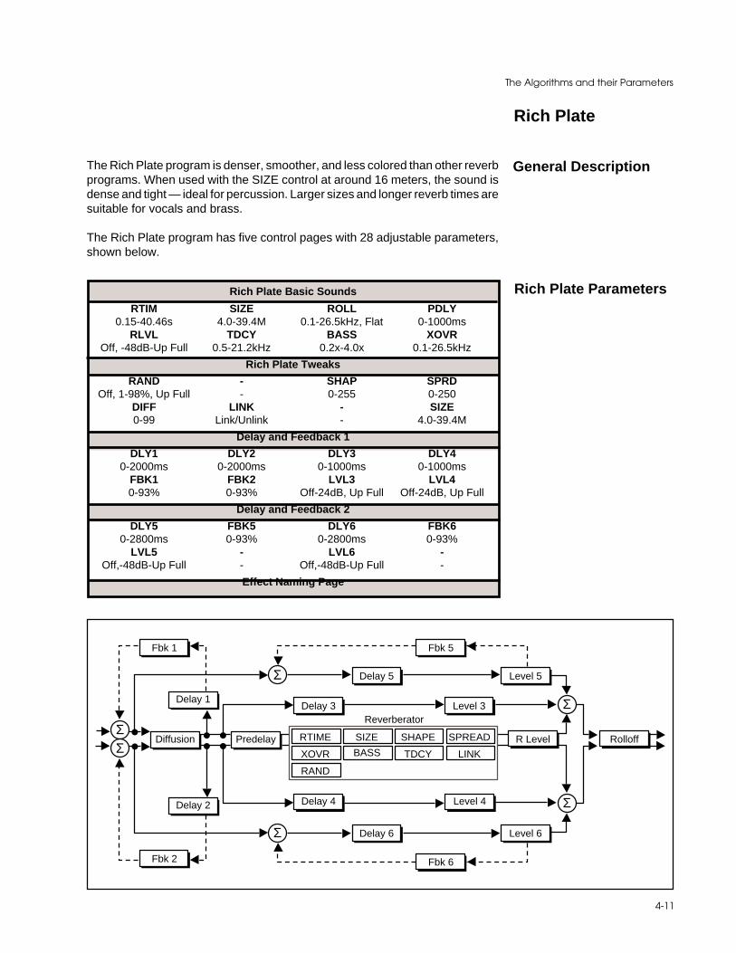
4-11
The Algorithms and their Parameters
Rich Plate
The Rich Plate program is denser, smoother, and less colored than other reverbprograms. When used with the SIZE control at around 16 meters, the sound isdense and tight — ideal for percussion. Larger sizes and longer reverb times aresuitable for vocals and brass.
The Rich Plate program has five control pages with 28 adjustable parameters,shown below.
General Description
Rich Plate Basic Sounds
RTIM SIZE ROLL PDLY0.15-40.46s 4.0-39.4M 0.1-26.5kHz, Flat 0-1000ms
RLVL TDCY BASS XOVROff, -48dB-Up Full 0.5-21.2kHz 0.2x-4.0x 0.1-26.5kHz
Rich Plate Tweaks
RAND - SHAP SPRDOff, 1-98%, Up Full - 0-255 0-250
DIFF LINK - SIZE0-99 Link/Unlink - 4.0-39.4M
Delay and Feedback 1
DLY1 DLY2 DLY3 DLY40-2000ms 0-2000ms 0-1000ms 0-1000ms
FBK1 FBK2 LVL3 LVL40-93% 0-93% Off-24dB, Up Full Off-24dB, Up Full
Delay and Feedback 2
DLY5 FBK5 DLY6 FBK60-2800ms 0-93% 0-2800ms 0-93%
LVL5 - LVL6 -Off,-48dB-Up Full - Off,-48dB-Up Full -
Effect Naming Page
Rich Plate Parameters
Fbk 1
Delay 1Delay 3
Diffusion Predelay
Delay 2 Delay 4
Fbk 2
Σ
Σ
Fbk 5
Delay 5 Level 5
Level 3
Level 4
Σ
Σ
Fbk 6
Level 6Delay 6
R Level
Reverberator
RolloffRTIME SIZE SHAPE SPREAD
XOVR BASS TDCY LINK
RAND
ΣΣ

Lexicon300 V 3.0 Owner's Manual
4-12
Rich Plate Basic Sounds Page
This control adjusts the reverberation time of the independent reverberator. Therange of action is limited. Be careful — both long and short reverb times maysound unnatural. If a much longer or shorter reverb time than the preset providesis desired, SIZE should be changed first.
SIZE allows you to vary the apparent size of the space over a wide range. SIZEis the most dramatic control, and must be selected to match the music or programmaterial. It should be the first control that you adjust to tailor the desired space.SIZE also affects the reverb time, in a similar way to the standard reverbprograms.
ROLL sets the frequency above which a 6 dB/octave low-pass filter attenuatesthe processed signal. It attenuates both pre-echoes and reverberant sound.High frequencies are often rolled off with this parameter, resulting in more naturalsounding reverberation.
PDLY adds an additional delay to the reflections and to the reverberation. Thiscontrol may be useful in a sound reinforcement situation, or for ambience effects.Both DDLY and PDLY have 4-sample (approximately 0.1msec) resolution.
RLVL sets the amount of reverberation in the processed signal. It is normallyFULL, but may be reduced for effects where the pre-echoes should dominate.
TDCY sets the frequency above which sounds decay at a progressively fasterrate. It filters all the sound except the pre-echoes. When set relatively low, it givesa darker tone to the reverberation, simulating the effect of air absorption in a realhall. TDCY also helps keep the ambience generated by the program frommuddying the direct sound.
BASS sets the reverb time for low-frequency signals, as a multiplier of the RTIMparameter. For example, if BASS is set to 2X, and RTIM is set to two seconds,the low frequency reverb time will be four seconds. For a natural-sounding hallambience, we recommend values of 1.5X or less.
XOVR sets the frequency at which the transition from RTIM to BASS takes place.XOVR should be set at least two octaves higher than the low frequency you wantto boost. For example, to boost a signal at 100 Hz, set XOVR to 400 Hz (Thissetting works well for classical music). XOVR works best around 400 for boostinglow frequencies, and around 1.5 kHz for cutting low frequencies.
RTIM (Reverb Time)
SIZE
ROLL (Hi Freq Rolloff)
PDLY (Pre-Delay)
RLVL (Reverb Level)
TDCY (Treble Decay)
BASS (Bass Multiply)
XOVR (Bass Crossover)

4-13
The Algorithms and their Parameters
Rich Plate Tweaks Page
RAND sets the rate of the randomization process. Plates should generally uselow amounts of randomization.
SHAP and SPRD work together to control the overall ambience of the reverbera-tion created by the 300. SHAP determines the contour of the reverberationenvelope. With SHAP all the way down, reverberation builds explosively, anddecays quickly.
As SHAP is advanced, reverberation builds up more slowly and sustains for thetime set by SPRD. With SHAP in the middle, the buildup and sustain of thereverberation envelope emulates a large concert hall (assuming that SPRD is atleast halfway up, and that SIZE is suitably large—30 meters or larger.)
SPRD works together with SHAP to control the duration of the initial ambiencecreated by the 300. Low SPRD settings result in a rapid onset of reverberationat the beginning of the envelope, with little or no sustain. Higher settings spreadout both the buildup and sustain.
DIFF controls the degree to which initial echo density increases over time. Highsettings of DIFF result in high initial buildup of echo density; low settings causelow initial buildup. Echo density is also affected by SIZE; smaller spaces willsound denser. To enhance percussion, use high settings of DIFF. For clearer,more natural vocals, mixes, and music, use low or moderate settings.
When LINK is set, the reverb time and spread values scale linearly as the SIZEcontrol is varied. For some special effects, RTIM and SPRD can be unlinked.
SIZE allows you to vary the apparent size of the space over a wide range. SIZEis the most dramatic control, and must be selected to match the music or programmaterial. It should be the first control that you adjust to tailor the desired space.SIZE also affects the reverb time, in a similar way to the standard reverbprograms.
Rich Plate Delay and Feedback Pre-Echoes Page
These pages provide control over three stereo delay pairs. All three are summedwith the output of the reverberator. Many, many different echo combinations arepossible.
DLY1 and DLY2 (0ms-2000ms) are recirculating delay lines to the left and rightchannel inputs. The path of either is picked off after the diffusor with the amountof recirculation defined by the adjustment of FBK1 (for DLY1) and FBK2 (forDLY2). DLY1 and DLY2 are the only delays which effectively feed back(recirculate) into the reverberator.
RAND (Randomization)
SHAP (Shape)
SPRD (Spread)
DIFF (Diffusion)
LINK
SIZE
DLY1 , DLY2
Lexicon300 V 3.0 Owner's Manual
4-14
FBK1 and FBK2 determine the amount of recirculation passed back through tothe left and right inputs.
DLY3 (0ms-1000ms) and DLY4 (0ms-1000ms) are also picked off after thediffusor. The level of each is controlled by LVL3 and LVL4, respectively.
LVL3 and LVL4 determine the loudness of DLY3 and DLY4.
DLY5 (0ms-2800ms) and DLY6 (0ms-2800ms) allow you to build non-diffusedrecirculating echoes independent of the reverberator. Each has a feedbackcontrol (FBK5 and FBK6).
FBK5 and FBK6 provide feedback control for DLY5 and DLY6.
LVL5 and LVL6 determine the loudness of DLY5 and DLY6. Remember, theseare undiffused pre-echoes.
DLY3 , DLY4
LVL3,LVL4
DLY5 , DLY6
FBK5, FBK6
LVL5,LVL6
FBK1 , FBK2
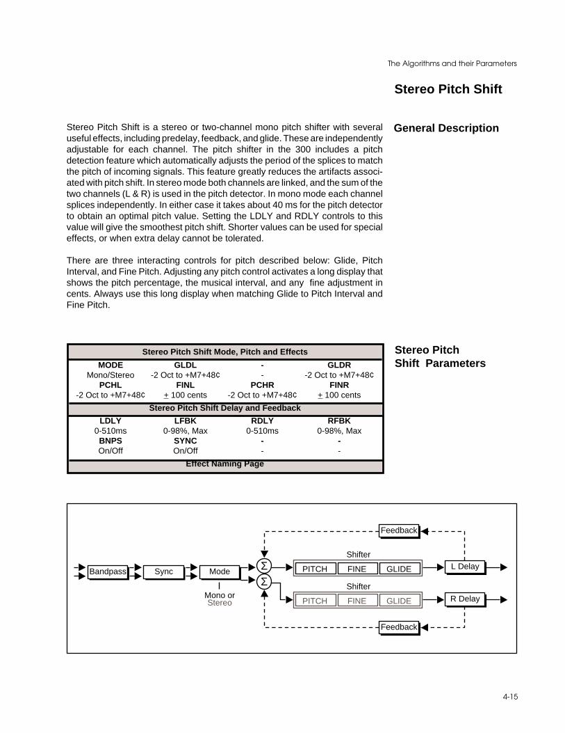
4-15
The Algorithms and their Parameters
Stereo Pitch Shift
Stereo Pitch Shift is a stereo or two-channel mono pitch shifter with severaluseful effects, including predelay, feedback, and glide. These are independentlyadjustable for each channel. The pitch shifter in the 300 includes a pitchdetection feature which automatically adjusts the period of the splices to matchthe pitch of incoming signals. This feature greatly reduces the artifacts associ-ated with pitch shift. In stereo mode both channels are linked, and the sum of thetwo channels (L & R) is used in the pitch detector. In mono mode each channelsplices independently. In either case it takes about 40 ms for the pitch detectorto obtain an optimal pitch value. Setting the LDLY and RDLY controls to thisvalue will give the smoothest pitch shift. Shorter values can be used for specialeffects, or when extra delay cannot be tolerated.
There are three interacting controls for pitch described below: Glide, PitchInterval, and Fine Pitch. Adjusting any pitch control activates a long display thatshows the pitch percentage, the musical interval, and any fine adjustment incents. Always use this long display when matching Glide to Pitch Interval andFine Pitch.
General Description
Stereo Pitch Shift Mode, Pitch and Effects
MODE GLDL - GLDRMono/Stereo -2 Oct to +M7+48¢ - -2 Oct to +M7+48¢
PCHL FINL PCHR FINR-2 Oct to +M7+48¢ + 100 cents -2 Oct to +M7+48¢ + 100 cents
Stereo Pitch Shift Delay and Feedback
LDLY LFBK RDLY RFBK0-510ms 0-98%, Max 0-510ms 0-98%, Max
BNPS SYNC - -On/Off On/Off - -
Effect Naming Page
Stereo PitchShift Parameters
Bandpass Sync Mode ΣΣ
Shifter
PITCH FINE GLIDE
Shifter
PITCH FINE GLIDE
L Delay
R Delay
Feedback
Feedback
Mono orStereo

Lexicon300 V 3.0 Owner's Manual
4-16
Stereo Pitch Shift Mode, Pitch and Effects Page
MODE selects stereo or mono mode. In stereo the two channels are linked, pitchshifting by the same amount and splicing at the same time.
GLDL affects both channels in stereo mode, and the left channel in mono mode.GLDR affects the right channel in mono mode. These controls change the pitchcontinuously over a range of -2octaves to +1 octave. This allows a glissando tobe performed, either manually or via MIDI.
PCHL adjusts the pitch interval of both channels in stereo mode, and the leftchannel in mono mode. The exact tuning can be altered by the fine pitch control,and the exact pitch shift in intervals and cents is displayed. The fine control mustbe set to the exact middle of its range if perfect pitch intervals are to be obtained.
In the long display, the Fine Pitch is shown by the number of cents added to, orsubtracted from, the semitone intervals. Remember that Pitch Interval willproduce exact intervals only if Fine Pitch is centered. The rightmost character inthe long display is an asterisk (*) if Fine Pitch is centered, and a '+' or '-' otherwise.When the VALUE key turns on the short value display, Fine Pitch is not shownin cents, but as a number ranging from -32 to +32 in order to give a clearindication of how much Pitch Interval has been changed. When '**' is shown, FinePitch is centered and inactive. As a rule, 1 count of Fine Pitch is worth 2 centsnear 200%, 3 cents near 100%, 6 cents near 50%, and 12 cents near 25%.
PCHR performs the same functions as the PCHL control, except that it is onlyactive in Mono mode, in which it adjusts the right channel.
FINL acts on both channels together in stereo mode, and the left channel in monomode. It adjusts pitch continuously over a range of a few hundred cents, and isadditive to the PCHL control. If PCHL is set to the middle of its range the FINLcontrol can be used to set very small values of pitch shift, producing a chorusingeffect.
FINR performs the same functions as the FINL control, except that it is onlyactive in Mono mode, in which it adjusts the right channel.
MODE
PCHL (Pitch IntervalStereo Left) and
PCHR (Pitch Interval R)
GLDL and GLDR(Glide Stereo Left
and Right)
FINL (Fine PitchStereo Left) and
FINR (Fine Pitch R)

4-17
The Algorithms and their Parameters
LDLY and RDLY
LFBK and R FBK
Stereo Pitch Shift Delay and Feedback Page
LDLY adjusts the length of a delay line in series with the left input. The range iszero to 510ms in 2ms steps.Pre-delay also affects the delay of any feedbackwhich is applied. In stereo mode the two pre-delays must be set to the samevalue, or the signals will not be in phase. Optimal pitch shift occurs when LDLYis about 40ms.
RDLY is the same as the LDLY, except that it acts upon the right channel.
L FBK and R FBK control the amount of positive feedback from the output of thepitch shift to the input of the pre-delay line. The control is adjustable from 0 to+99%. Some very useful efects can be obtained by combining pitch shift, delay,and feedback.
BNPS is a band-pass filter which rolls off the frequency responce of the audiobefore the splicing algorithm. The -3dB point is 100 Hz. The purpose of the band-pass filter is to give the pitch shifter less information than it actually needs todecide when to make the splice. Typically, this will inprove the performance ofthe pitch shifter.
SYNC is only active in STEREO mode. This control forces an exact sync of thetwo channels when the control is turned from 0 to 1. When SYNC is 1, there isan automatic re-syncing any time the two channels differ in phase by about 10samples. This can occur if PCHL or LDLY is changed. Re-syncing can cause asmall click in the output. If the pitch shifter is being used to manually pitch-correctclassical music using the GLDL control, it may be better to set SYNC to 0, or Off.There is an automatic sync tracking feature which will keep the two channelslocked to within 2 samples. If precise synchronization is desired, the GLDL orPCHL controls should be set, SYNC should be set from 0 to 1, and then the pitchshould not be changed. The two channels will remain precisely synchronized,even though both are continually changing the splice length in response to theincoming pitches.
BNPS
SYNC
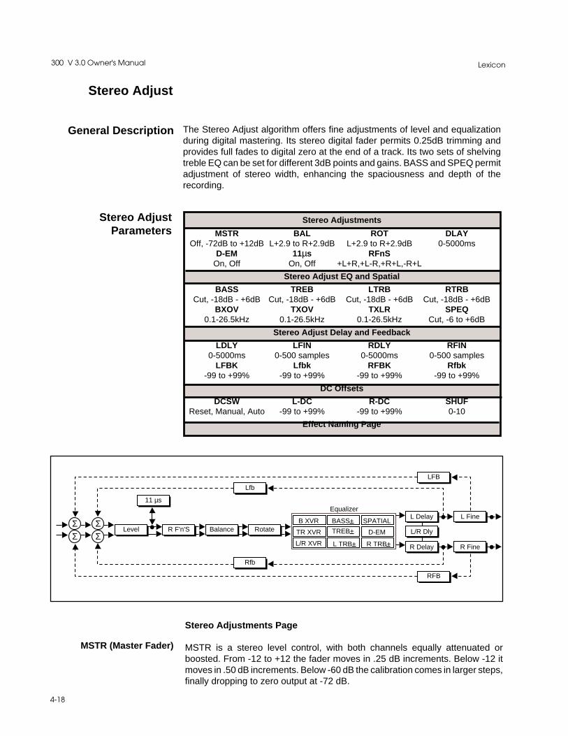
Lexicon300 V 3.0 Owner's Manual
4-18
The Stereo Adjust algorithm offers fine adjustments of level and equalizationduring digital mastering. Its stereo digital fader permits 0.25dB trimming andprovides full fades to digital zero at the end of a track. Its two sets of shelvingtreble EQ can be set for different 3dB points and gains. BASS and SPEQ permitadjustment of stereo width, enhancing the spaciousness and depth of therecording.
General Description
Stereo Adjustments
MSTR BAL ROT DLAYOff, -72dB to +12dB L+2.9 to R+2.9dB L+2.9 to R+2.9dB 0-5000ms
D-EM 11µs RFnSOn, Off On, Off +L+R,+L-R,+R+L,-R+L
Stereo Adjust EQ and Spatial
BASS TREB LTRB RTRBCut, -18dB - +6dB Cut, -18dB - +6dB Cut, -18dB - +6dB Cut, -18dB - +6dB
BXOV TXOV TXLR SPEQ0.1-26.5kHz 0.1-26.5kHz 0.1-26.5kHz Cut, -6 to +6dB
Stereo Adjust Delay and Feedback
LDLY LFIN RDLY RFIN0-5000ms 0-500 samples 0-5000ms 0-500 samples
LFBK Lfbk RFBK Rfbk-99 to +99% -99 to +99% -99 to +99% -99 to +99%
DC Offsets
DCSW L-DC R-DC SHUFReset, Manual, Auto -99 to +99% -99 to +99% 0-10
Effect Naming Page
Stereo AdjustParameters
Stereo Adjust
Σ ΣΣ Σ
Level
11 µs
R F'n'S Balance Rotate
L Delay
L/R Dly
R Delay
Equalizer
B XVR BASS+ SPATIAL
TR XVR TREB+ D-EM
L/R XVR L TRB+ R TRB+
Lfb
Rfb
L Fine
R Fine
LFB
RFB
Stereo Adjustments Page
MSTR is a stereo level control, with both channels equally attenuated orboosted. From -12 to +12 the fader moves in .25 dB increments. Below -12 itmoves in .50 dB increments. Below -60 dB the calibration comes in larger steps,finally dropping to zero output at -72 dB.
MSTR (Master Fader)
4-19
The Algorithms and their Parameters
BAL implements a sine/cosine balance adjustment. Balance is smoothly ad-justed over a wide range, with excellent resolution in the critical area aroundzero. The display indicates the actual channel gains as the control is varied.
ROT is similar to BAL, but it treats stereo information somewhat differently. Anysignal panned to the center (mono) will be treated by ROT exactly as it would betreated by BAL. However, if a signal is panned full right and the control is movedtoward the right, instead of simply being attenuated (as BAL would do) the rightchannel is inverted in phase and added to the left channel. A stereo imageappears to rotate when this control is used. Ambient information is preserved,and both channels appear to retain equal loudness.
If stereo material is recorded with a coincident pair of figure-of-eight micro-phones, moving the ROT slider is exactly equivalent to rotating the microphonepair. Other microphone arrays and multimicrophone setups do not rotateperfectly, but using this control is frequently preferable to simply adjustingbalance. The display shows the actual channel gains for a continually pannedsource.
DLAY controls a 5-second stereo delay line, with a resolution of 10 milliseconds.Separate mono and fine controls are on the Delay page below. This is a post-processing full-level delay, and is always in the circuit.
When D-Em is On, the incoming signal is digitally de-emphasized. This shouldnot be used unless the material has been emphasized in the record process—such as a PCM-F1 tape. Note that the emphasis bit in the incoming signal canbe turned off from the 300 front panel. See Chapter 2: System Operation: SetupEdit.
When digital de-emphasis is applied, the CD mastering lab must be informedthat the tape is not emphasized, and the CD emphasis bit should be manuallyset to Off. Mastering labs are happy to do this, but they must be informed!
When this control is on, the left channel is delayed relative to the right by 11µsec(1/2 sample). This control specifically corrects for the timing error betweenchannels caused by consumer digital systems (e.g. the Sony PCM-F1 and itsprogeny) that time-share single analog converters. Turning on this delay timealigns the left channel audio data for compatibility with professional systems.
RFnS is used for digitally correcting probelms you used to be able to fix (orcreate) by switching analog cables around. The normal setting is +L to the leftoutput and +R to the right output. Other settings should only be used whencorrecting some problem created previously in the recording process.
+L+R = Normal Routing+L-R = Right Channel polarity inverted (flipped)+R+L = Left and Right Channels swapped-R+L = Right flipped and swapped with Left
BAL (Balance)
ROT (Rotate)
D-EM(De-emphasis On/Off)
DLAY
11 µsec (1/2 sample)
RFnS (Right ChannelFlip 'n' Swap)

Lexicon300 V 3.0 Owner's Manual
4-20
Stereo Adjust EQ and Spatial Page
BASS is a 6dB/octave shelving EQ control with a range of +6 dB boost and -18dBcut. It moves in .50 dB steps from +6 to -6 dB. The crossover point is adjustedwith BXOV. BASS acts on both stereo channels equally.
TREB is a 6 dB/octave shelving EQ controls with a range of +6 dB boost and-18dB cut. It moves in .50 dB steps from +6 to -6 dB. The crossover point isadjusted with TXOV. TREB acts on both stereo channels equally.
These controls allow independent adjustment of left and right treble. They maybe used together with the stereo adjustments to create a 12 dB/octave cut orboost. Note that the 3 dB frequencies can be different from the stereo set.
BXOV sets the crossover point for BASS. When BASS is set to full cut, the levelis -3 dB at the frequency set with BXOV.
TXOV sets the crossover point for TREB. When TREB is set to full cut, the levelis -3 dB at the frequency set with TXOV.
TXLR sets the crossover point for LTRB and RTRB. When either is set to fullcut, the level is -3 dB at the frequency set with TXLR.
SPEQ sets the amount of a crossfeed between channels. The signal first goesthrough a 6 dB/octave low-pass filter whose frequency is set with BXOV.
When SPEQ is set positive (above 0) the crossfeed has a negative sign. WhenSPEQ is set negative (below 0), the crossfeed has a positive sign. When thecontrol is set to either maximum or minimum, the gain in the crossfeed circuit isunity.
The result of this control is to change the separation of low frequency stereosignals. When the control is raised, low frequencies in the sum (mono) channelare reduced, and low frequencies in the difference (stereo) channel are raised.With the control at maximum, low frequency mono signals are completelyremoved. This represents an extreme setting which should seldom be neededin practice.
With material which has stereo bass information, or which contains somereverberation, the effect of raising SPEQ is to increase the sense of spacious-ness and depth of the sound. It is particularly useful on material recorded withpanpots, or coincident and semi-coincident microphone technique.
When most of the bass in a recording is in the sum (mono) channel, raisingSPEQ may reduce the bass level. This effect can be compensated for by raisingthe overall bass level with BASS. Since both controls use the same BXOVsetting, this compensation will be quite accurate as long as SPEQ is set to lessthan 3 dB boost.
BASS (Bass EQ)
TREB (Treble EQ)
LTRB and RTRB
BXOV (Bass Crossover)
TXOV (Stereo TrebleCrossover)
SPEQ (Spatial EQ)
TXLR (IndependentTreble Crossover)

4-21
The Algorithms and their Parameters
Stereo Adjust Delay and Feedback Page
These controls give individual channel control over the 5-second post-equaliza-tion delay line.
5-second, 10 milliseconds per step, mono control for the left channel.
DLAY + LDLY must not total more than 5,000 milliseconds.
5-second, 10 milliseconds per step, mono control for the right channel.
DLAY + RDLY must not total more than 5,000 milliseconds.
Fine Sample Accurate Delays
These can be used for subtle time alignment adjustments. The 300 will correctlydisplay the resulting time shift as a function of the sampling rate. As many as 500samples can be added to any stereo/coarse delay setting for a maximumpossible delay per channel of 5 seconds + 500 samples.
48 kHz = 20.833 microseconds per sample44.1 kHz = 22.676 microseconds per sample32 kHz = 31.25 microseconds per sample
500-sample, 1 sample per step, mono fine adjust for the left channel.
500-sample, 1 sample per step, mono fine adjust for the right channel.
Two feedback paths are available per channel: overall and fine. Overallfeedback is the total delay of DLAY + L(R)DLY + L(R)FIN, and is useful for longecho effects.
Fine Feedback is only around the Fine Delay and can be used for very shortdelay effects and coloration.
All feedback gains are adjustable in 1% increments from -99% to +99%. If themagnitudes of both feedback gains for a channel sum to more than 100%, thatchannel will take off and overload.
On the 300 Effects Feedback page, overall and fine are distinguished by upperand lower case lettering:
LFBK = Overall Left Channel FeedbackLfbk = Fine Left Channel FeedbackRFBK = Overall Right Channel FeedbackRfbk = Fine Right Channel Feedback
LDLY(Left Channel Coarse)
RDLY(Right Channel Coarse)
RFIN (Right Channel Fine)
LFIN (Left Channel Fine)

Lexicon300 V 3.0 Owner's Manual
4-22
Stereo Adjust DC Offsets Page
This control provides three choices: RESET, MANUAL ADJUST and AUTOADJUST. RESET disables all DC adjustment. AUTO ADJUST enables routinesfor correcting DC offset from material recorded through analog-to-digital con-verters that are not properly trimmed for DC. MANUAL ADJUST allows Softknobselection of offset values.
Replaces any previously obtained value with the value set here via the soft knob.The display indicates the percent of the correction.
SHUF controls a spatial equalizer designed to make recordings from a dummyhead, or closely-spaced omni microphones, more suitable for loudspeakerreproduction. Due to the close spacing of the microphones, there is very littledifference between the two stereo channels below about 300Hz. The shufflerrestores the low frequency separation by first matrixing the L and R signals intoL+R and L-R, bass-boosting the L-R channel, then rematrixing back to L and R.The effect is to convert small time differences (which are not audible inloudspeaker reproduction) between the two microphones into level differences,which are audible. The effect can be dramatic.
The frequency below which the boost acts is set by the SHUF control. A settingof 5 will give a 3dB L-R boost at about 150Hz; a setting of 10 will be 3dB up at250Hz. Response rises at 6dB/octave below this frequency. More than 18dB ofgain can be obtained at 20Hz when SHUF is set to 10.
This control has been optimized for true binaural recordings, where the differ-ence signal at low frequencies is minimal. If it is used on ordinary stereo material,or with binaural material to which reverberation has been added, excessive lowfrequency difference signals can result. On such material, it is better to use theSPEQ control which will achieve a similar result.
The SHUF control varies from 0 (shuffler off) to a maximum of 10. While theorywould suggest a setting of 10 for a dummy head, a setting of 5 appears to be moreuseful in practice. The setting is very much a matter of taste. If closely spacedmicrophones are used, the setting will scale inversely with the microphonedistance in centimeters. For a spacing of 15cm, try a shuffler setting of 5. For aspacing of 30cm, try a setting of 3. For a spacing of 7cm, try a setting of 10.
DCSW (DC Offset Nulling)
L-DC and R-DC(Lch and Rch DC Offset)
SHUF (Binaural Shuffler)

4-23
The Algorithms and their Parameters
"Split" SetupAlgorithms
General Description
Dual DelaysThe Dual Delay algorithm consists of 2 types of delay lines: Gliding Flangedelays and Fixed delays. This is a true stereo algorithm. (If run in a Dual Monosetup, however, it will be mono.)
Two independet gliding flange predelays are available, each with a 20ms rangein single sample steps. There is also a ganged stereo gliding flange delay. Thereare two flange gain controls which vary the overall amount of flange effect.
The flange glides are typically modulated by the internal LFO. Setting the flangegains very high will cause an “over the top” type of flange to occur as the flangeglide delays cross over the predelay pointers. The outputs of the flange delaysare fed to the delay left and delay right lines which are 2.5 seconds long. Onceinto these delay lines, you can create many different delay effects. There are twoprogrammable taps on each delay line. DLY1 (left) and DLY2 (right) can beprogrammed anywhere along this 2.5 second path. There will, however, be noapparant delay unless a feedback value is assigned to the delay values via FBK1and FBK2. All Pass filters, or diffusors, in line with the feedback paths are labeledAPD (All Pass Delay) and APG (All Pass Gain). The actual “tuning” of the All passdelay is accomplished with the APD control. The amount of diffusion is set byAPG. When APG is turned high and FBK1 is adjusted away from the 0% value,each feedback loop will be rediffused.
DLY3 and DLY4 are cross feedback delay lines. They are also adjustableanywhere along the 2.5 second delay line. DLY3 feeds from the left delayposition to the input of the right delay line. The same is true with DLY4 feedinginto the left delay line. The feedback parameters adjust the amount (level)passed into the destination delay lines.
The last pair of delay pointers (LDLY and RDLY) can be thought of asindependently adjustable post delays. These can be adjusted anywhere alongthe 2.5 second delay line.
The output of each delay line can be positioned anywhere in the stereo pan field.LPAN adjusts the position of the left delay loop; RPAN positions the output of theright delay loop.

Lexicon300 V 3.0 Owner's Manual
4-24
Dual DelaysParameters
Σ ΣDelay 2
APG 2 APD 2 FBK 2
Delay 4 R Delay R Pan
Σ ΣDelay 3 L Delay L Pan
APG 1 APD 1 FBK 1
Delay 1
Fbk 3
Fbk 4
Flanger
Σ
Σ
L PDLY L GAIN
R PDLY R GAIN
FLNGDLY
FLNGDLY
Dual Delay Adjustments
DM: FDLY LFBD RFBD0-479smp=0-10ms 0-479smp=0-10ms 0-479smp=0-10ms
MchB - LFLG RFLG- 0-99% 0-99%
Delay and Feedback Page 1
DM: DLY1 FBK1 -0-119996smp= 0-99%
0-2498.9msMchB DLY2 FBK2 -
0-19996smp= 0-99%0-2498.9ms@48kHz
Diffusor Controls
DM: APD1 APG1 -0-19996smp= 0-1910-2498.9ms
MchB APD2 APG2 -0-19996smp= 0-1910-2498.9ms
Delay and Feedback Page 2
DM: DLY3 FBK3 -0-19996smp= 0-99%0-2498.9ms
MchB DLY4 FBK4 -0-19996smp= 0-99%0-2498.9ms
Diffusor Controls
DM: LDLY LPAN -0-19996smp= L, 0-98%R/L, R0-2498.9ms
MchB RDLY RPAN -0-19996smp= L, 0-98%R/L, R0-2498.9ms
Effect Naming Page
4-25
The Algorithms and their Parameters
Dual Delays Adjustments Page
FDLY is a separate 20 ms ganged stereo delay line which is controllable in singlesample steps.
LFBD and RFBD are base delays which get summed with the stereo gangedflange delay.These base delays are adjustable in single sample steps through-out a 20 millisecond range.
LFLG and RFLG are flange gains which are adjustabe as a feed forward amplifierloop (+99% positive value) or feedback amplifier loop (-99% negative value).
Dual Delays Diffusors, Feedback and Delays
DLY1 and DLY2 set the delay values for the respective left to left and right to rightfeedback loops
FBK1 and FBK2 set the gain of feedback for each of the delay lines. Availablevalues range from -99% to +99% gain.
APD1 and APD2 are diffusors (All Pass Delays) in series with the feedback loopsassociated with DLY1 and DLY2. Their controls range from 0 to 10 ms. Thesecontrols essentially “tune” the diffuor delay line.
APG1 and APG2 are gains associated with the diffusors. You can think of themas controlling the amount of diffusion.
DLY3 controls the delay time which cross-feedbacks to the input of DLY2. DLY4controls the delay time which cross-feedbacks to the input of DLY1.
FBK3 and FBK4 control the gain of the feedbacks going with each of theirrespective delay lines.
LDLY sets the left channel delay line's time. RDLY sets the right channel delayline's time.
LPAN adjusts the left delay channel pan placement. RPAN adjusts the rightdelay channel pan placement
LFBD and RFBD(Left and Right FlangeBase Delays)
LFLG and RFLG(Left and RightFlange Gain)
FDLY (Flange Delay)
DLY1 and DLY2
FBK1 and FBK2
APD1 and APD 2(All Pass Left and RightDelays)
APG1 and APG 2(All Pass Left and RightGain)
DLY3 and DLY 4
FBK3 and FBK4
LDLY and RDLY
LPAN and RPAN

Lexicon300 V 3.0 Owner's Manual
4-26
Σ Diffusion
Split Chamber
RTIME SIZE SHAPE SPREAD
XOVR BASS TDCY LINK
RAND
Predelay
Split Chamber
Split ChamberParameters
The Split Chamber program provides several presets which can be loaded intoany Dual Mono or Cascade setup. In the Dual Mono setups it passes audio MonoIn-Mono Out. In the Cascade setups, audio is routed Mono In-Stereo Out. TheSplit Chamber program can simulate many different types of acoustic spaces ormechanical devices.
Th Split Chamber algorithm is great on anything. SIZEs of 25 and larger set alower acoustic density. SHAP and SPRD help create the illusion of larger spaceswhicle using short reverb times. As in the Random Hall algorithm, the LINKparameter couples SIZE to the RTIM and SPRD. Unlink provides a method ofsetting stable RTIM and SPRD values, then adjusting SIZE to set the rightdensity and “tuning”. Split Chamber is bright by design, so you may want to uselower values of TDCY — maybe even as low as 1.0kHz or 500Hz.
The randomization circuit in Split Chamber is designed to reduce coloration and/or frequency nodes caused by low frequency input. If you want to create yourown special Chambers or Halls, you should keep RAND set to 90 or 95.
Typically, SIZEs of 14-24 meters with TDCYs higher than3.4kHz will emulatebright sounding metal plates. Remember to set SHAP and SPRD to extremelylow values to maintain the explosiveness of the reverb decay. Because platesare very diffuse, any preset mimicking a plate should have DIFF set relativelyhigh (70-80), while BASS is kept to some value less than 1.2kHz.
DIFF and PDLY precede the reverberator. When Chamber programs are loadedinto Dual Mono setups, the audio will be Mono In-Mono Out. When loaded intoCascade setups, audio is routed summed Mono In-Stereo Out.
Split Chamber Adjustments Page 1
DM: RTIM SIZE PDLY.09-24.11s 4.0-66.4M 0-1000ms
MchA TDCY SHAP SPRD0.5-21.2kHz 0-255 0-202
Split Chamber Adjustments Page 2
DM: BASS DIFF RAND0.2-4.0x 0-99 Off,0-98%,Up Full
MchA XOVR LINK -0.1-26.5kHz Link/Unlink -
Effect Naming Page
General Description
4-27
The Algorithms and their Parameters
RTIM (Mid-FrequencyReverb Time)
SIZE
PDLY (Pre-Delay)
TDCY (Treble Decay)
SHAP (Shape)
Split Chamber Adjustments Page 1
RTIM sets the reverb time for mid-frequency signals. Because low-frequencyreverb time (BASS) is a multiplier of RTIM, RTIM acts as a master control for thereverb time.
SIZE sets the rate of buildup of diffusion after the initial period (which is controlledby DIFF). It also acts as a master control for RTIM and SPRD. The SIZE controlchanges a reverb sound from very large to very small. Generally, you should setthe SIZE control to approximate the size of the acoustic space you are trying tocreate, before adjusting anything else. The size in meters is roughly equal to thelongest dimension of the space. Moving SIZE while a signal is present maycause audible transients on critical material.
The apparent size of the space created is actually a combination of the settingsof the SIZE, SHAP, and SPRD controls. Small acoustic spaces are character-ized by a rapid buildup of diffusion. However, both small and large spacesfrequently have an uneven buildup of initial reverberation. This uneven buildupis controlled by the SPRD and SHAP controls.
PDLY adjusts an additional time delay between the input of signal and the onsetof reverberation. The control is not intended to mimic the time delays in naturalspaces. In real rooms the build-up of reverberation is gradual, and the initial timegap is usually relatively short. Natural spaces are best emulated by setting SHAPat a middle value and adjusting SPRD for the desired effective pre-delay.
Additional delay added with the PDLY control can increase the initial time gapslightly, emulating a situation where reverberant pick-up microphones arelocated much further from the source than the main microphones. If less thanabout 30ms of pre-delay is added, this additional delay can add clarity with somemusic, but it can also sound unnatural. Large pre-delays can be useful for slap-echo effects.
TDCY sets the frequency above which sounds decay at a progressively fasterrate. It filters all the sound except the pre-echoes. When set relatively low, it givesa darker tone to the reverberation, simulating the effect of air absorption in a realhall. TDCY also helps keep the ambience generated by the program frommuddying the direct sound.
SHAP and SPRD work together to control the overall ambience of the reverbera-tion created by the 300. SHAP determines the contour of the reverberationenvelope. With SHAP all the way down, reverberation builds explosively, anddecays quickly.
As SHAP is advanced, reverberation builds up more slowly and sustains for thetime set by SPRD. With SHAP in the middle, the buildup and sustain of thereverberation envelope emulates a large concert hall (assuming that SPRD is atleast halfway up, and that SIZE is suitably large—30 meters or larger.)

Lexicon300 V 3.0 Owner's Manual
4-28
SPRD works together with SHAP to control the duration of the initial ambiencecreated by the 300. Low SPRD settings result in a rapid onset of reverberationat the beginning of the envelope, with little or no sustain. Higher settings spreadout both the buildup and sustain.
Split Chamber Adjustments Page 2
BASS sets the reverb time for low-frequency signals, as a multiplier of the RTIMparameter. For example, if BASS is set to 2X, and RTIM is set to two seconds,the low frequency reverb time will be four seconds. For a natural-sounding hallambience, we recommend values of 1.5X or less.
DIFF controls the degree to which initial echo density increases over time. Highsettings of DIFF result in high initial buildup of echo density; low settings causelow initial buildup. Echo density is also affected by SIZE; smaller spaces willsound denser. To enhance percussion, use high settings of DIFF. For clearer,more natural vocals, mixes, and music, use low or moderate settings.
RAND sets the distance in time that the early reflections will move.
XOVR sets the frequency at which the transition from RTIM to BASS takes place.XOVR should be set at least two octaves higher than the low frequency you wantto boost. For example, to boost a signal at 100 Hz, set XOVR to 400 Hz (Thissetting works well for classical music). XOVR works best around 400 for boostinglow frequencies, and around 1.5 kHz for cutting low frequencies.
When LINK is set, the reverb time and spread values scale linearly as the SIZEcontrol is varied. For some special effects, RTIM and SPRD can be unlinked.
SPRD (Spread)
BASS (Bass Multiply)
DIFF (Diffusion)
RAND (Randomization)
XOVR (Bass Crossover)
LINK
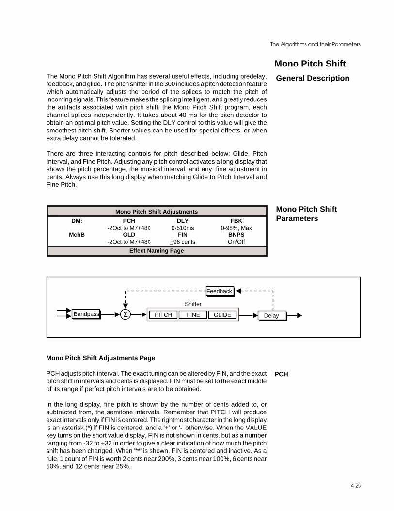
4-29
The Algorithms and their Parameters
General Description
Mono Pitch ShiftThe Mono Pitch Shift Algorithm has several useful effects, including predelay,feedback, and glide. The pitch shifter in the 300 includes a pitch detection featurewhich automatically adjusts the period of the splices to match the pitch ofincoming signals. This feature makes the splicing intelligent, and greatly reducesthe artifacts associated with pitch shift. the Mono Pitch Shift program, eachchannel splices independently. It takes about 40 ms for the pitch detector toobtain an optimal pitch value. Setting the DLY control to this value will give thesmoothest pitch shift. Shorter values can be used for special effects, or whenextra delay cannot be tolerated.
There are three interacting controls for pitch described below: Glide, PitchInterval, and Fine Pitch. Adjusting any pitch control activates a long display thatshows the pitch percentage, the musical interval, and any fine adjustment incents. Always use this long display when matching Glide to Pitch Interval andFine Pitch.
Mono Pitch ShiftParameters
Mono Pitch Shift Adjustments
DM: PCH DLY FBK-2Oct to M7+48¢ 0-510ms 0-98%, Max
MchB GLD FIN BNPS-2Oct to M7+48¢ +96 cents On/Off
Effect Naming Page
ΣShifter
PITCH FINE GLIDEBandpass Delay
Feedback
Mono Pitch Shift Adjustments Page
PCH adjusts pitch interval. The exact tuning can be altered by FIN, and the exactpitch shift in intervals and cents is displayed. FIN must be set to the exact middleof its range if perfect pitch intervals are to be obtained.
In the long display, fine pitch is shown by the number of cents added to, orsubtracted from, the semitone intervals. Remember that PITCH will produceexact intervals only if FIN is centered. The rightmost character in the long displayis an asterisk (*) if FIN is centered, and a '+' or '-' otherwise. When the VALUEkey turns on the short value display, FIN is not shown in cents, but as a numberranging from -32 to +32 in order to give a clear indication of how much the pitchshift has been changed. When '**' is shown, FIN is centered and inactive. As arule, 1 count of FIN is worth 2 cents near 200%, 3 cents near 100%, 6 cents near50%, and 12 cents near 25%.
PCH

Lexicon300 V 3.0 Owner's Manual
4-30
DLY adjusts the length of a delay line from zero to 510ms in 2ms steps.Optimalpitch shift occurs when DLY is about 40ms.
FBK controls the amount of positive feedback from the output of the pitch shiftto the input of the pre-delay line. The control is adjustable from 0 to +99%. Somevery useful efects can be obtained by combining pitch shift, delay, and feedback.
GLD changes the pitch continuously over a range of -2 octaves (25%) to +1octave (199%). This allows a glissando to be performed, either manually or viaMIDI.
FIN adjusts pitch continuously over a range of -2 octaves to +1 octave. Thisallows a glissando to be performed, either manually or via MIDI.
BNPS is a band-pass filter which rolls off the frequency responce of the audiobefore the splicing algorithm. The -3dB point is 100 Hz. The purpose of the band-pass filter is to give the pitch shifter less information than it actually needs todecide when to make the splice. Typically, this will further improve the perform-ance of the pitch shifter.
FBK
DLY
FIN
GLD
BNPS

4-31
The Algorithms and their Parameters
General Description
CompressorThe Compressor algorithm is a true digital compressor which will run in eitherDual Mono or Cascade Setups. In Dual Mono Setups, it configures to mono inmono out; in Cascade Setups it configures as a true stereo effect. Thecompressor can be described as an upwards averaging compressor. Digitalcompressors, like analog compressors, decrease audio above a given thresh-old. Unlike analog compressors, they increase gain below the threshold. Theresult from either analog or digital compression is exactly the same — lessdynamic range.
As shown in the diagram below, the audio path takes two routes. One path goesthrough a predelay mechanism which delays the audio a maximum of 48 ms. Theother path sends control information (dependent on the settings of slope,threshold, attack and release) to “digital VCA’s” labeled MAX COMP GAIN andEXP GAIN. As the signal crosses the threshold point, both Compressor Gainand Expansion Gain vary constantly. Compressor Gain determines the maxi-mum amount of gain increase below the threshold; Expansion Gain determinesthe maximum amount of gain attenuation below the threshold.
Generally, digital compression requires lower threshold settings than analogcompression. The reason for this is that there is no such thing as headroom ina digital system — dBfs (Digital Full scale [0VU]) is the maximum level audio.Audio dynamics below full scale, however, can be manipulated and modified.
Example1. Press SETUP SELECT and turn the Softknob to select Cascade Setup: 313
STEREO COMP. This preset loads the stereo compressor into both ma-chines but mixes Machine B to full dry. (no point in compressing twice!)
2. Press ENTER to load the preset.
3. Press EFFECT EDIT. Note the front panel level meters and try to establishthe average input level. A simple approach might be to look at the peaks andvalleys in signal amplitude and estimate the middle ground. If this all seamstoo complicated, just select THRS and set it to -17dB.
4. Select GAIN and set it to Max (9 dB). At this point there should be no effecton the dynamics because you’ve not yet adjusted the slope parameter.
5. Select SLP and increase it to 2.0 : 1 (a 2 to 1 Compression Slope). Now youshould hear a change. If you still do not hear a net effect, readjust THRS untilsomething becomes audible. Remember, as you adjust the thresholdclockwise (closer to digital full scale) more and more audio will be gainincreased — overload can occur!!
The whole purpose of a digital compressor is to maintain peaks while compress-ing lower level audio signals upwards. If you think about it in terms of the mostsignificant and least significant bits, you would never want to reduce the mostsignificant bits — you want to increase the least sigificant bits.
Adding some pre-delay gives the control mechanism time to react before theaudio reaches the digital VCA. Of course, the more predelay you add, the more“out of sync” the audio will become. Attack constants should be kept to shortvalues (7,15, or 30ms). A good starting point for release time is 91 or 114 ms.

Lexicon300 V 3.0 Owner's Manual
4-32
LR
Expander
Compressor
Predelay CmpGain ExpGain
X SLOPE X THRS
SLOPE THRS
ATTACK RELEASE
Compressor Adjustments
DM: PDLY ATC RTC0-48ms 0-960ms 0-4000ms
MchB THRS GAIN SLP0 to -40dB 0-24dB 1.0-99.99:1
Expander Adjustments
DM: EXTH EXG EXSL0 to -70dB 0-24dB 1.0-8.93:1
MchB - - -- - -
Effect Naming Page
CompressorParameters
Compressor Adjustments Page
PDLY sets the predelay of the audio before the digital VCA.
ATC adjusts the attack time constant.
RTC allows adjustment of the release time constant.
THRS sets the level at which compression starts.
GAIN adjusts the gain of low level signals (below the compression threshold).
SLP controls the slope of the gain reduction curve or the ratio of input level versusoutput level.
PDLY
ATC (Attack)
RTC (ReleaseTime Constant)
THRS (Threshold)
GAIN
SLP (Slope)
4-33
The Algorithms and their Parameters
Expander Adjustments Page
EXTH sets the threshold at which the expander starts to work.
EXG sets the amount of negative gain.
EXSL controls the slope of the expander circuit.
EXSL
EXTH
EXG
Dither is a low-level pseudo-random signal which is added to digital audio toreduce quantization noise, in effect, by replacing it with a "nicer sounding" noise.It is possible to filter the quantization noise in such a way that almost all of thenoise within the frequency range where human hearing is most acute is shiftedto higher frequencies. This is called psychoacoustically optimized noise shaping(PONS) because it takes advantage of the variations in the ear's sensitivity tonoise within the 20 Hz - 20 kHz range.
PONS Adjustments
CC: DITH PONS -0-254 On/Off -
MchA - - -- - -
Effect Naming Page
PONS Adjustments Page
DITH allows you to vary the amount of dither gain added to the signal.
This control allows you to turn the dither function on or off.
General Description
PONS
PONS Parameters
DITH (Dither Gain)
PONS
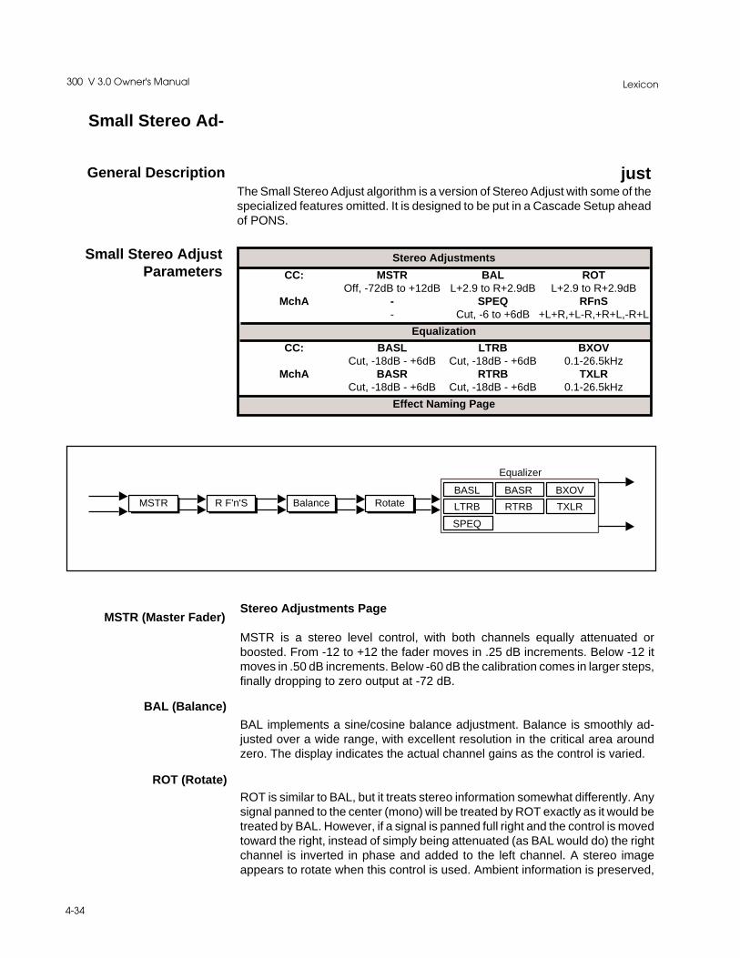
Lexicon300 V 3.0 Owner's Manual
4-34
justThe Small Stereo Adjust algorithm is a version of Stereo Adjust with some of thespecialized features omitted. It is designed to be put in a Cascade Setup aheadof PONS.
General Description
Small Stereo Ad-
Stereo Adjustments
CC: MSTR BAL ROTOff, -72dB to +12dB L+2.9 to R+2.9dB L+2.9 to R+2.9dB
MchA - SPEQ RFnS- Cut, -6 to +6dB +L+R,+L-R,+R+L,-R+L
Equalization
CC: BASL LTRB BXOVCut, -18dB - +6dB Cut, -18dB - +6dB 0.1-26.5kHz
MchA BASR RTRB TXLRCut, -18dB - +6dB Cut, -18dB - +6dB 0.1-26.5kHz
Effect Naming Page
Small Stereo AdjustParameters
MSTR R F'n'S Balance Rotate
Equalizer
BASL BASR BXOV
LTRB RTRB TXLR
SPEQ
Stereo Adjustments Page
MSTR is a stereo level control, with both channels equally attenuated orboosted. From -12 to +12 the fader moves in .25 dB increments. Below -12 itmoves in .50 dB increments. Below -60 dB the calibration comes in larger steps,finally dropping to zero output at -72 dB.
BAL implements a sine/cosine balance adjustment. Balance is smoothly ad-justed over a wide range, with excellent resolution in the critical area aroundzero. The display indicates the actual channel gains as the control is varied.
ROT is similar to BAL, but it treats stereo information somewhat differently. Anysignal panned to the center (mono) will be treated by ROT exactly as it would betreated by BAL. However, if a signal is panned full right and the control is movedtoward the right, instead of simply being attenuated (as BAL would do) the rightchannel is inverted in phase and added to the left channel. A stereo imageappears to rotate when this control is used. Ambient information is preserved,
MSTR (Master Fader)
ROT (Rotate)
BAL (Balance)

4-35
The Algorithms and their Parameters
and both channels appear to retain equal loudness.
If stereo material is recorded with a coincident pair of figure-of-eight micro-phones, moving the ROT slider is exactly equivalent to rotating the microphonepair. Other microphone arrays and multimicrophone setups do not rotateperfectly, but using this control is frequently preferable to simply adjustingbalance. The display shows the actual channel gains for a continually pannedsource.
RFnS is used for digitally correcting probelms you used to be able to fix (orcreate) by switching analog cables around. The normal setting is +L to the leftoutput and +R to the right output. Other settings should only be used whencorrecting some problem created previously in the recording process.
+L+R = Normal Routing+L-R = Right Channel polarity inverted (flipped)+R+L = Left and Right Channels swapped-R+L = Right flipped and swapped with Left
Equalization Page
BASL and BASR are 6dB/octave shelving EQ controls with a range of +6 dBboost and -18dB cut. They move in .50 dB steps from +6 to -6 dB. The crossoverpoint is adjusted with BXOV.
These controls allow independent adjustment of left and right treble. They maybe used together with the stereo adjustments to create a 12 dB/octave cut orboost. Note that the 3 dB frequencies can be different from the stereo set.
BXOV sets the crossover point for BASL and BASR. When BASL and BASR areset to full cut, the level is -3 dB at the frequency set with BXOV.
TXLR sets the crossover point for LTRB and RTRB. When either is set to fullcut, the level is -3 dB at the frequency set with TXLR.
SPEQ sets the amount of a crossfeed between channels. The signal first goesthrough a 6 dB/octave low-pass filter whose frequency is set with BXOV. WhenSPEQ is set positive (above 0) the crossfeed has a negative sign. When SPEQis set negative (below 0), the crossfeed has a positive sign. When the control isset to either maximum or minimum, the gain in the crossfeed circuit is unity.
The result of this control is to change the separation of low frequency stereosignals. When the control is raised, low frequencies in the sum (mono) channelare reduced, and low frequencies in the difference (stereo) channel are raised.With the control at maximum, low frequency mono signals are completelyremoved. This represents an extreme setting which should seldom be needed
RFnS (Right ChannelFlip 'n' Swap)
BASL and BASR
LTRB and RTRB
BXOV (Bass Crossover)
TXLR (IndependentTreble Crossover)
SPEQ (Spatial EQ)
Lexicon300 V 3.0 Owner's Manual
4-36
in practice.
With material which has stereo bass information, or which contains somereverberation, the effect of raising SPEQ is to increase the sense of spacious-ness and depth of the sound. It is particularly useful on material recorded withpanpots, or coincident and semi-coincident microphone technique.
When most of the bass in a recording is in the sum (mono) channel, raisingSPEQ may reduce the bass level. This effect can be compensated for by raisingthe overall bass level with BASL and BASR. Since both controls use the sameBXOV setting, this compensation will be quite accurate as long as SPEQ is setto less than 3 dB boost.

5-1
The Presets
5The Presets

Lexicon300 V 3.0 Owner's Manual
5-2
The Setup Presets
Single Setup(and Effect) Presets
The 300 is shipped with 100 setup presets (50 Single Setups, and 25 each of thetwo split setup types), as well as 50 setup registers for storing your modifiedsetups.
Single Effects are only available in Single-type Setups. Therefore, the descrip-tions (and the names) of the setup and effect presets are identical. An asterisk(*) indicates there is a Soft knob patch which controls various parameters withone controller.
# Name Algorithm Description
P101 Large Hall Random Hall Used as a great standard reference point. The hall size is big, with agentle bloom in the reverberation envelope. The first set of pre-echoesis set to 14 and 20 ms, but the levels are set to OFF. Set levels to tasteif you want to add some initial reflections.
P102 Medium Hall Random Hall Similar to Large Hall, but the size is not as big (29.3) and the reverb timeis proportionately shorter. The same arrangement exists for thepre-echoes.
P103 Small Hall Random Hall An even smaller version, a bit denser — good for general reverb fill.
P104 * Church Random Hall This preset is big and spread out. There are 2 close in pre-echoes and2 longer and softer delays which have low recirculation added. The Softknob controls the Size parameter(Spread and Shape are intrinsicallylinked), and Treble Decay. As the Soft knob value is increased, RoomSize is decreased and Treble Decay is brightened.
P105 * Rooms Random Hall This preset links Room Size to the Soft knob. As you turn the Soft knob,Room Size will go from its initial value of 19.1Meters down to 9.6Meters.These Rooms are diffuse and very articulate sounding. Lower values ofRoom Size tend to be more resonant sounding. Good for dialog reads.
P106 RehursalRoom Random Hall This is a dense, brashy-sounding space with the listener in the backof the room. Rolling off the high-cut filter will put the carpeting on thewalls. Room size is set to 15.2M, so the sound is very tight. Good onvocals and fill.
P107 * Chamber Random Hall Like the Room Preset, the Soft knob is patched to the Size parameter.Advancing the softknob reduces the Size value from a maximum of 25.3Meters to 14.1 Meters. Imagine a chamber with a reflective plasterfinish.
P108 LiveDrumRoom Random Hall Bright and tight. The Soft knob is patched to the Size and Rolloffparameters so that advancing the knob value makes the room alittle bigger and brighter.
P109 * Studio A Random Hall This preset sounds like the “big” rooms ($125/hour). The Softknob ispatched to Delay Levels 3 and 4, as well as to the Rolloff and TrebleDecay parameters. Advancing the Soft knob increases all of theseparameters, making the studio brighter and more reflective.
P110 * Studio B Random Hall A smaller Studio area than Studio A. The Soft knob is patched toPre-echo Levels 3 and 4. Advancing the Soft knob makes the Studiomore reflective.
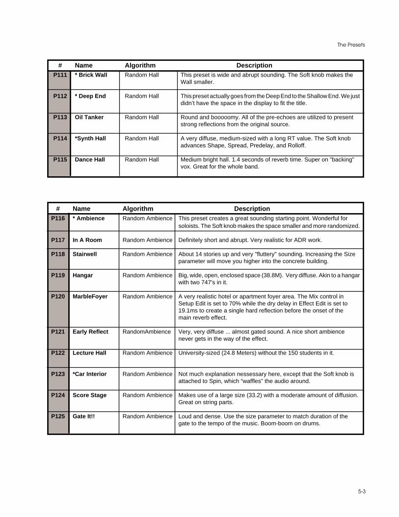
5-3
The Presets
# Name Algorithm DescriptionP111 * Brick Wall Random Hall This preset is wide and abrupt sounding. The Soft knob makes the
Wall smaller.
P112 * Deep End Random Hall This preset actually goes from the Deep End to the Shallow End. We justdidn’t have the space in the display to fit the title.
P113 Oil Tanker Random Hall Round and booooomy. All of the pre-echoes are utilized to presentstrong reflections from the original source.
P114 *Synth Hall Random Hall A very diffuse, medium-sized with a long RT value. The Soft knobadvances Shape, Spread, Predelay, and Rolloff.
P115 Dance Hall Random Hall Medium bright hall. 1.4 seconds of reverb time. Super on "backing"vox. Great for the whole band.
# Name Algorithm DescriptionP116 * Ambience Random Ambience This preset creates a great sounding starting point. Wonderful for
soloists. The Soft knob makes the space smaller and more randomized.
P117 In A Room Random Ambience Definitely short and abrupt. Very realistic for ADR work.
P118 Stairwell Random Ambience About 14 stories up and very "fluttery" sounding. Increasing the Sizeparameter will move you higher into the concrete building.
P119 Hangar Random Ambience Big, wide, open, enclosed space (38.8M). Very diffuse. Akin to a hangarwith two 747's in it.
P120 MarbleFoyer Random Ambience A very realistic hotel or apartment foyer area. The Mix control inSetup Edit is set to 70% while the dry delay in Effect Edit is set to19.1ms to create a single hard reflection before the onset of themain reverb effect.
P121 Early Reflect RandomAmbience Very, very diffuse ... almost gated sound. A nice short ambiencenever gets in the way of the effect.
P122 Lecture Hall Random Ambience University-sized (24.8 Meters) without the 150 students in it.
P123 *Car Interior Random Ambience Not much explanation nessessary here, except that the Soft knob isattached to Spin, which “waffles” the audio around.
P124 Score Stage Random Ambience Makes use of a large size (33.2) with a moderate amount of diffusion.Great on string parts.
P125 Gate It!! Random Ambience Loud and dense. Use the size parameter to match duration of thegate to the tempo of the music. Boom-boom on drums.
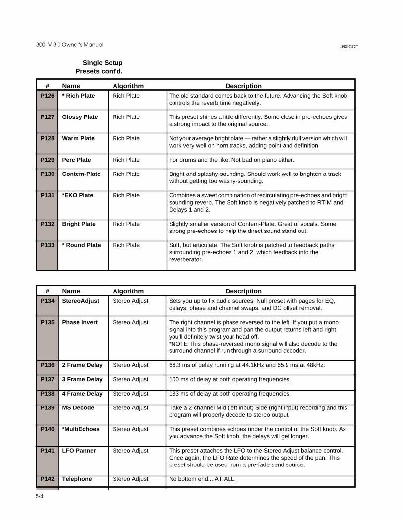
Lexicon300 V 3.0 Owner's Manual
5-4
Single Setup Presets cont'd.
# Name Algorithm DescriptionP126 * Rich Plate Rich Plate The old standard comes back to the future. Advancing the Soft knob
controls the reverb time negatively.
P127 Glossy Plate Rich Plate This preset shines a little differently. Some close in pre-echoes givesa strong impact to the original source.
P128 Warm Plate Rich Plate Not your average bright plate — rather a slightly dull version which willwork very well on horn tracks, adding point and definition.
P129 Perc Plate Rich Plate For drums and the like. Not bad on piano either.
P130 Contem-Plate Rich Plate Bright and splashy-sounding. Should work well to brighten a trackwithout getting too washy-sounding.
P131 *EKO Plate Rich Plate Combines a sweet combination of recirculating pre-echoes and brightsounding reverb. The Soft knob is negatively patched to RTIM andDelays 1 and 2.
P132 Bright Plate Rich Plate Slightly smaller version of Contem-Plate. Great of vocals. Somestrong pre-echoes to help the direct sound stand out.
P133 * Round Plate Rich Plate Soft, but articulate. The Soft knob is patched to feedback pathssurrounding pre-echoes 1 and 2, which feedback into thereverberator.
# Name Algorithm DescriptionP134 StereoAdjust Stereo Adjust Sets you up to fix audio sources. Null preset with pages for EQ,
delays, phase and channel swaps, and DC offset removal.
P135 Phase Invert Stereo Adjust The right channel is phase reversed to the left. If you put a monosignal into this program and pan the output returns left and right,you’ll definitely twist your head off.*NOTE This phase-reversed mono signal will also decode to thesurround channel if run through a surround decoder.
P136 2 Frame Delay Stereo Adjust 66.3 ms of delay running at 44.1kHz and 65.9 ms at 48kHz.
P137 3 Frame Delay Stereo Adjust 100 ms of delay at both operating frequencies.
P138 4 Frame Delay Stereo Adjust 133 ms of delay at both operating frequencies.
P139 MS Decode Stereo Adjust Take a 2-channel Mid (left input) Side (right input) recording and thisprogram will properly decode to stereo output.
P140 *MultiEchoes Stereo Adjust This preset combines echoes under the control of the Soft knob. Asyou advance the Soft knob, the delays will get longer.
P141 LFO Panner Stereo Adjust This preset attaches the LFO to the Stereo Adjust balance control.Once again, the LFO Rate determines the speed of the pan. Thispreset should be used from a pre-fade send source.
P142 Telephone Stereo Adjust No bottom end....AT ALL.
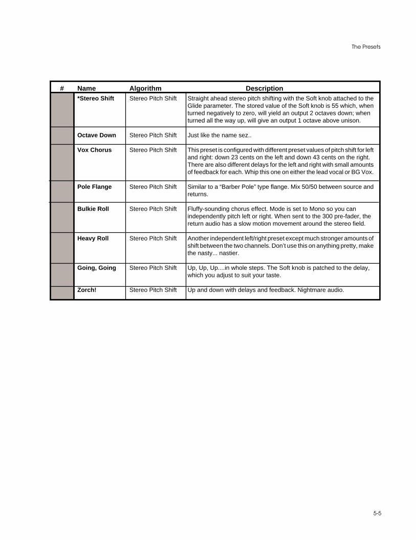
5-5
The Presets
# Name Algorithm DescriptionP143 *Stereo Shift Stereo Pitch Shift Straight ahead stereo pitch shifting with the Soft knob attached to the
Glide parameter. The stored value of the Soft knob is 55 which, whenturned negatively to zero, will yield an output 2 octaves down; whenturned all the way up, will give an output 1 octave above unison.
P144 Octave Down Stereo Pitch Shift Just like the name sez..
P145 Vox Chorus Stereo Pitch Shift This preset is configured with different preset values of pitch shift for leftand right: down 23 cents on the left and down 43 cents on the right.There are also different delays for the left and right with small amountsof feedback for each. Whip this one on either the lead vocal or BG Vox.
P146 Pole Flange Stereo Pitch Shift Similar to a “Barber Pole” type flange. Mix 50/50 between source andreturns.
P147 Bulkie Roll Stereo Pitch Shift Fluffy-sounding chorus effect. Mode is set to Mono so you canindependently pitch left or right. When sent to the 300 pre-fader, thereturn audio has a slow motion movement around the stereo field.
P148 Heavy Roll Stereo Pitch Shift Another independent left/right preset except much stronger amounts ofshift between the two channels. Don’t use this on anything pretty, makethe nasty... nastier.
P149 Going, Going Stereo Pitch Shift Up, Up, Up....in whole steps. The Soft knob is patched to the delay,which you adjust to suit your taste.
P150 Zorch! Stereo Pitch Shift Up and down with delays and feedback. Nightmare audio.
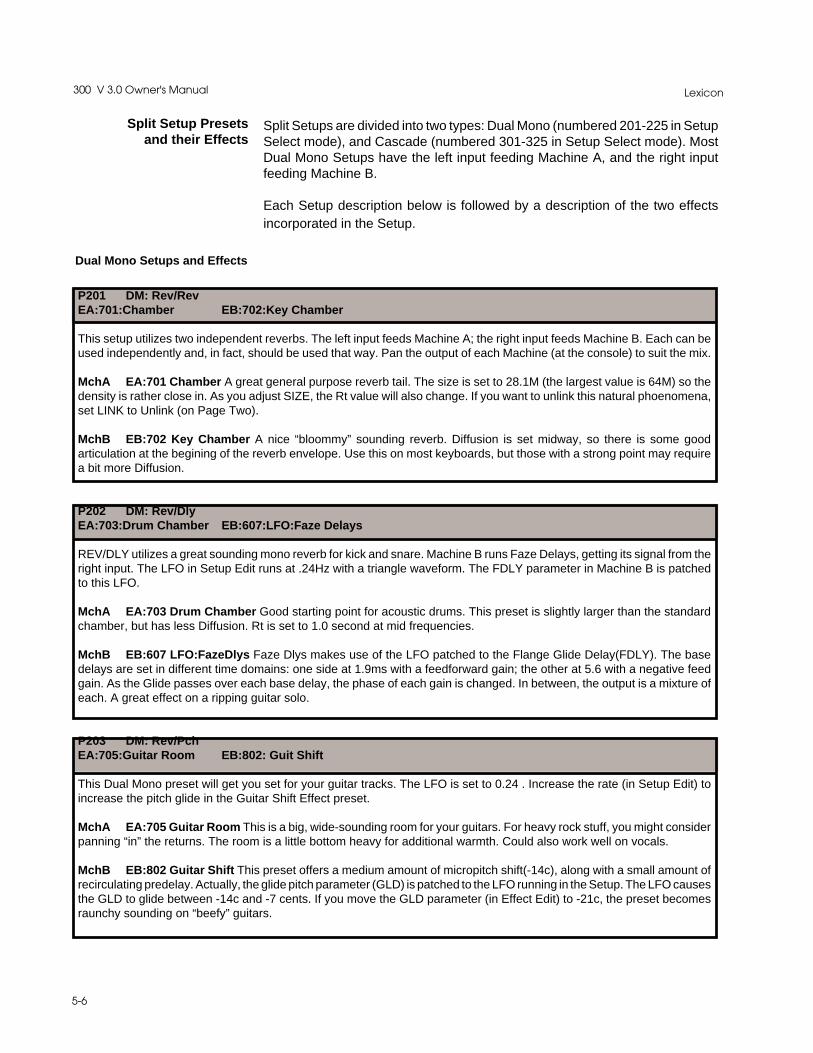
Lexicon300 V 3.0 Owner's Manual
5-6
Split Setup Presetsand their Effects
Split Setups are divided into two types: Dual Mono (numbered 201-225 in SetupSelect mode), and Cascade (numbered 301-325 in Setup Select mode). MostDual Mono Setups have the left input feeding Machine A, and the right inputfeeding Machine B.
Each Setup description below is followed by a description of the two effectsincorporated in the Setup.
Dual Mono Setups and Effects
P201 DM: Rev/RevEA:701:Chamber EB:702:Key Chamber
This setup utilizes two independent reverbs. The left input feeds Machine A; the right input feeds Machine B. Each can beused independently and, in fact, should be used that way. Pan the output of each Machine (at the console) to suit the mix.
MchA EA:701 Chamber A great general purpose reverb tail. The size is set to 28.1M (the largest value is 64M) so thedensity is rather close in. As you adjust SIZE, the Rt value will also change. If you want to unlink this natural phoenomena,set LINK to Unlink (on Page Two).
MchB EB:702 Key Chamber A nice “bloommy” sounding reverb. Diffusion is set midway, so there is some goodarticulation at the begining of the reverb envelope. Use this on most keyboards, but those with a strong point may requirea bit more Diffusion.
P202 DM: Rev/DlyEA:703:Drum Chamber EB:607:LFO:Faze Delays
REV/DLY utilizes a great sounding mono reverb for kick and snare. Machine B runs Faze Delays, getting its signal from theright input. The LFO in Setup Edit runs at .24Hz with a triangle waveform. The FDLY parameter in Machine B is patchedto this LFO.
MchA EA:703 Drum Chamber Good starting point for acoustic drums. This preset is slightly larger than the standardchamber, but has less Diffusion. Rt is set to 1.0 second at mid frequencies.
MchB EB:607 LFO:FazeDlys Faze Dlys makes use of the LFO patched to the Flange Glide Delay(FDLY). The basedelays are set in different time domains: one side at 1.9ms with a feedforward gain; the other at 5.6 with a negative feedgain. As the Glide passes over each base delay, the phase of each gain is changed. In between, the output is a mixture ofeach. A great effect on a ripping guitar solo.
P203 DM: Rev/PchEA:705:Guitar Room EB:802: Guit Shift
This Dual Mono preset will get you set for your guitar tracks. The LFO is set to 0.24 . Increase the rate (in Setup Edit) toincrease the pitch glide in the Guitar Shift Effect preset.
MchA EA:705 Guitar Room This is a big, wide-sounding room for your guitars. For heavy rock stuff, you might considerpanning “in” the returns. The room is a little bottom heavy for additional warmth. Could also work well on vocals.
MchB EB:802 Guitar Shift This preset offers a medium amount of micropitch shift(-14c), along with a small amount ofrecirculating predelay. Actually, the glide pitch parameter (GLD) is patched to the LFO running in the Setup. The LFO causesthe GLD to glide between -14c and -7 cents. If you move the GLD parameter (in Effect Edit) to -21c, the preset becomesraunchy sounding on “beefy” guitars.

5-7
The Presets
P204 DM: Rev/CompEA:707:”U”Chamber EB:901:EZ Comp2:1
This preset utilizes a chamber preset on the left input and a compressor preset on the right input. Typically, EZ Comp2:1should be used at a patch point on the console. If used on an effect send, make sure the fader sends are pre-fade, or a phaseerror will occur between the fader signal and the return to the console.
MchA EA:707 “U” Chamber This preset is shaped liked an upside down “U” with the speaker on top of the wall, and amicrophone on either side of the wall.
MchB EB:901 EZ Comp 2:1 An “easy” preset to add to an overall stereo mix or mono or stereo submix. You might needto adjust Threshold to make it work for the particular signal you feed it. Release is set to gently (2:1) fall away after 363ms.
P205 DM: Dly/DlyEA:609: Chorus EB:612: Chorus+EKOz
Think of this preset as the chorus preset for mono sources. Left input feeds Machine A; right feeds Machine B. Both effectshave their flange glides attached to the Setup LFO. The LFO is set to 1.38Hz with a sine waveform.
MchA EA:609 Chorus The Chorus preset makes use of a small variation in the glide delay to modulate the sound. Theglide moves between 9.7ms and 11.8ms. Advancing the LFO to values near 1.50Hz to 2.0 Hz, yields a nice chorusing effect.There are no other delay lines, but the output lines are channel-swapped such that the left input passes to the right outputand vice-versa. In a Dual Mono Setup, this is ,of course, inaudible.
MchB EB:612 Chorus+EKOz Chorus+EKOz makes use of the flange gliding delay (via the Setup LFO) and severallonger recurring echoes.
P206 DM: *Dly/PchEA:601: *Dual Delays EB:804: Sky Down
This preset incorporates a Setup Soft knob patch to the effect in Machine A (*Dual Delays). Paging up one page will activatethe Soft knob as a multi-parameter controller. In this Setup, going to this location in Setup Select mode will change the stereodelay parameter in preset 601 which is loaded into Machine A (left input). Machine B (right input) loads a pitch shift program.
MchA EA:601 *Dual Delays Baseline effect with the Soft knob patched to the last two delay lines in the signal path.Advancing the Soft knob will cause the two post-delays to move in sync out to almost 3000ms.
MchB EB:804 Sky Down This preset tunnels downward due to the liberal amount of delay feedback. If the effect is tooheavy, lower the Feedback value. This preset has no Mod Edit patches.
P207 DM: Dly/CompEA:602 Space Delays EB:902 DrumComp3:1
This preset presents a delay preset to the left effect input/output, and a Drum compressor preset to the right effect input/output.
MchA EA:602 Space Delays This preset incorporates a bit of left-right diffused delay, along with some small delay offsetbetween left and right delay outputs. If the effect is too strong, try lowering feedback levels for delays 3 and 4.
MchB EB:902 DrumComp 3:1 This is a bit more aggressive, with 7dB of boost below the selected threshold. A quickrelease of 58ms snaps up the volume. As with all compressor presets, Threshold is the critical parameter.
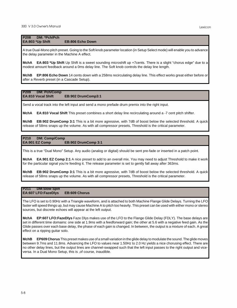
Lexicon300 V 3.0 Owner's Manual
5-8
P208 DM: *Pch/PchEA:803 *Up Shift EB:806 Echo Down
A true Dual-Mono pitch preset. Going to the Soft knob parameter location (in Setup Select mode) will enable you to advancethe delay parameter in the Machine A effect.
MchA EA:803 *Up Shift Up Shift is a sweet sounding microshift up +7cents. There is a slight “chorus edge” due to amodest amount feedback around a 0ms delay line. The Soft knob controls the delay line length.
MchB EP:806 Echo Down 14 cents down with a 258ms recirculating delay line. This effect works great either before orafter a Reverb preset (in a Cascade Setup).
P209 DM: Pch/CompEA:810 Vocal Shift EB:902 DrumComp3:1
Send a vocal track into the left input and send a mono prefade drum premix into the right input.
MchA EA:810 Vocal Shift This preset combines a short delay line recirculating around a -7 cent pitch shifter.
MchB EB:902 DrumComp 3:1 This is a bit more agressive, with 7dB of boost below the selected threshold. A quickrelease of 58ms snaps up the volume. As with all compressor presets, Threshold is the critical parameter.
P210 DM: Comp/CompEA:901 EZ Comp EB:902 DrumComp 3:1
This is a true “Dual Mono” Setup. Any audio (analog or digital) should be sent pre-fade or inserted in a patch point.
MchA EA:901 EZ Comp 2:1 A nice preset to add to an overall mix. You may need to adjust Threshold to make it workfor the particular signal you’re feeding it. The release parameter is set to gently fall away after 363ms.
MchB EB:902 DrumComp 3:1 This is a bit more agressive, with 7dB of boost below the selected threshold. A quickrelease of 58ms snaps up the volume. As with all compressor presets, Threshold is the critical parameter.
P211 DM:Slow SpinEA:607 LFO:FazeDlys EB:609 Chorus
The LFO is set to 0.90Hz with a Triangle waveform, and is attached to both Machine Flange Glide Delays. Turning the LFOfaster will speed things up, but may cause Machine A to pitch too heavily. This preset can be used with either mono or stereosources, but discrete echoes will appear at the left output.
MchA EP:607 LFO:FazeDlys Faze Dlys makes use of the LFO to the Flange Glide Delay (FDLY). The base delays areset in different time domains: one side at 1.9ms with a feedforward gain; the other at 5.6 with a negative feed gain. As theGlide passes over each base delay, the phase of each gain is changed. In between, the output is a mixture of each. A greateffect on a ripping guitar solo.
MchB EP609 Chorus This preset makes use of a small variation in the glide delay to modulate the sound. The glide movesbetween 9.7ms and 11.8ms. Advancing the LFO to values near 1.50Hz to 2.0 Hz yields a nice chorusing effect. There areno other delay lines, but the output lines are channel-swapped such that the left input passes to the right output and vice-versa. In a Dual Mono Setup, this is ,of course, inaudible.
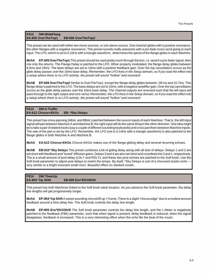
5-9
The Presets
P212 DM:WideFlangEA:605 OverTheTop1 EB:606 OverTheTop2
This preset can be used with either two mono sources, or one stereo source. One channel glides with a positive resonance,the other flanges with a negative resonance. This preset sounds really awesome with a pre-fade mono send going to eachinput. The LFO, which is set to 0.22Hz with a triangle waveform, determines the speed of the flange glides in each Machine.
MchA EP:605 OverTheTop1 This preset should be used pretty much through the box, i.e. send it a pre-fader signal, thenmix only the returns. The Flange Delay is patched to the LFO. When properly modulated, the flange delay glides between9.5ms and 18ms. The base delays are set to 10ms with a positive feedback gain. Over the top cancellation occurs as theglide delay passes over the 10ms base delay.!Remember, the LFO lives in the Setup domain, so if you load the effect intoa setup where there is no LFO activity, the preset will sound “hollow” and resonant!
MchB EP:606 OverTheTop2 Similar to OverTheTop1, except the flange delay glides between .08 ms and 10.7ms. Thisflange delay is patched to the LFO. The base delays are set to 10ms, with a negative amplifier gain. Over the top cancellationoccurs as the glide delay passes over the 10ms base delay. The channel outputs are reversed such that the left input willpass through to the right output and vice-versa.!Remember, the LFO lives in the Setup domain, so if you load the effect intoa setup where there is no LFO activity, the preset will sound “hollow” and resonant!
P213 DM:X-TrafficEA:612 Chorus+EKOz EB: *Sky Delays
This preset has cross panning (ABAL and BBAL) patched between the source inputs of each Machine. That is, the left inputsignal will pan between Machine A and Machine B; the right input will do the same thing in the other direction. One idea mightbe to take a pair of related tracks (say a couple of different sounding keyboards) and cross pan them between Machine inputs.The rate of the pan is set by the LFO. Remember, the LFO (set to 0.14Hz with a triangle waveform) is also patched to theflange glides in both Machine A and Machine B.
MchA EA:612 Chorus+EKOz Chorus+EKOz makes use of the flange gliding delay and several recurring echoes.
MchB EB:610 *Sky Delays This preset combines a bit of giding delay along with all sets of delays. Delays 1 and 2 areset short with feedback and “tuned” diffusion gains. Delays 3 and 4 are also set short and crossfeed into 2 and 1, respectively.The is a small amount of post delay (LDLY and RDLY), and these two post echoes are patched to the Soft knob. Use theSoft knob parameter to adjust post delays to match the tempo. By itself, *Sky Delays is sort of a chorused cluster echo —very similar to a bright resonant small room. Beautiful effect on stacked vocals.
P214 DM:*GearUpEA:803 *Up Shift EB:805 Env*EKOShift
This preset has both Machines linked to the Soft knob value location. As you advance the Soft knob parameter, the delayline lengths will get progressively longer.
MchA EP:803 *Up Shift A sweet sounding microshift up +7cents. There is a slight “chorus edge” due to a modest amountfeedback around a 0ms delay line. The Soft knob controls the delay line length.
MchB EP:805 Env*EKOShift The Soft knob parameter controls the delay line length, and the L-Meter is negativelypatched to the feedback (FBK) parameter, such that when signal is present, delay feedback is reduced; when the signaldisappears, feedback is increased. This is a very interesting effect when the echo fits the beat of the music.

Lexicon300 V 3.0 Owner's Manual
5-10
P215 DM:TwoRoomsEA:P715 Joe’s Garage EB:P709 Basement
Garage band and Basement band. Use with Dual Mono sources and place behind the source.
MchA EA:715 Joe’s Garage Two bays, no waiting. Small and bright.
MchB EP:709 Basement Tight and short. Size is 15.8 meters, and the tonality is fairly resonant sounding. Almost trashy-sounding (low diffusion), and will certainly get so if the Rt is made longer.
P216 DM:TwoHallsEA:720 Recital Hall EB:710 Big Hall
Two mono halls (left to left, and right to right). Try reversing the returns relative to the sources at the console for a differenteffect.
MchA EA:720 Recital Hall This medium large (44.5M) space opens sound sources beautifully. Made for string pads andvoice.
MchB EP:710 Big Hall Big and open sounding. The 44ms of predelay help to separate the stage from the seating area.Real good sounding on ballad vocals.
P217 DM:*VerbsEA:717 *Drum Rooms EB:711 *Great Room
Advancing the Soft knob parameter will change the characteristics of each Machine preset as described below...
MchA EP:717 *Drum Rooms Deep and narrow in shape. The Soft knob parameter makes the room “shallower” andgated sounding.
MchB EP:711 *Great Room The Soft knob parameter advances Predelay and Spread to open the room up nearly to hallproportions. Bass multiply (BASS) is set to 2.0X to round out the bottom end.
P218 DM:*RevPanEA:707 “U”Chamber EB:708 *’L’Chamber
This preset has two Setup Edit parameters patched to the LFO; ABAL and BBAL. Sources going into Machine A and B willcross pan between them, as in X-Traffic. The LFO is set to 0.06Hz with a triangle waveform.
MchA EA:707 “U” Chamber This preset is shaped liked an upside down “U” with the speaker on top of the wall and amicrophone on either side of the wall.
MchB EP:708 *“L” Chamber “L” Chamber mimics the shape of a chamber shaped like that letter. A little bigger than the“U” chamber. Reverb time is patched to the Soft knob parameter.
P219 DM:Up&DownEA:807 HalfStepsUp EB:808 HalfStepsDn
Left to Machine A and right to Machine B. Diabolical and horrifying sounding.
MchA EA:807 HalfStepsUp Just what you think...
MchB EB:808 HalfStepsDn(down) Ditto...

5-11
The Presets
P220 DM:MyGuitarEA:802 Guit Shift EB:614 Env:Peak
Great stuff for either a mono or stereo guitar. Machine B should get a very strong, if not a total, pre-fade signal.
MchA EA:802 Guitar Shift This preset offers a moderate amount of micropitch shift(-14c), along with a small amount ofrecirculating predelay. Raunchy sounding on beefy” guitars.
MchB EB:614 Env:Peak This preset is similar to an OverTheTop type of effect, except the flange delay is patched to themeter balistics. Depending on the dynamics of your guitar playing, you may wish to adjust the scaling parameter which isfound in the Mod Edit patch.
P221 DM:EnvSpoogeEA:614 Env:Peak EB:608 Env:Phazer
This preset uses two effects which have meter ballistics patched to the flange glide delays, with a twist: the Machine A ModEdit patch gets its modulation information from the R-meter; the Machine B flange glide Mod patch is specified to modulatefrom the ballistics of the L-meter. One input modulates the other — A T-shirt to the engineer who gets the most creative.
MchA EP:614 Env:Peak This preset is similar to an OverTheTop type effect except the flange delay is patched to meterballistics. Some modification of the scaling parameter in the Mod Edit patch may be nessessary to suit Machine B ballistics.
MchB EP:608 Env:Phazer This preset makes use of a patch between the L-Meter and the flange glide delay. As signalbecomes stronger, the glide delay drops in the time domain, eventually crossing the 5.2ms base delays. As audio signalstrength lessens, the glide returns to its preset value of 10ms. Very good on vocals. To make this effect work properly, besure to drive the 300 to within 12dB of full scale (dBfs). Remember, in this setup the effects are reversed from the meterballistics which drive them. Good Luck!!!
P222 DM:Flng&DlysEA:615 Negative Flang EB:602 Space Dlys
This is a true Dual Mono Setup. The Setup LFO is set to 0.6Hz with a triangle waveform. It drives the flange glide delay (FDLY)in Machine A.
MchA EA:615 NegativeFlng This is a really stiff flange which goes almost 20ms deep. Flange gain is set extremelynegative, so the sound is tunnel-like.
MchB EB:602 Space Delays This preset incorporates a bit of multi-diffused delays along with some small delay offsetsbetween the post delay outputs. If the effect is too strong, try lowering feedback levels for delays 3 and 4. You may hear akind of resonant “tuning” to the return signal. This is because the flange delay has gain (LFLG and RFLG) in the circuit, butit is not patched to the LFO. It just stays in its preset location at 8.6ms. If you want to change the “tuning,” adjust flange glide(FDLY) in Effect Edit mode to another value.
P223 DM:*Dly DazeEA:604*3VoiceDlys EB:603*PingoPongo
The Soft knob parameter affects the delay spacing in both Machine effect presets. Increasing the Soft knob parameter valuewill make each delay effect longer and longer; decreasing it will make each delay effect shorter. The Soft knob value is setto 12 when the setup is selected.
MchA EA:604 *3Voice Dlys Two taps (Delays 3 and 4 ) are set with delay ratios of 1:2, meaning that, when one is 200ms,the other is 400ms, or when one is 359, the other is 718ms. This relationship is patched to the Soft knob parameter in SetupSelect mode.
MchB EB:603 *Pingo Pongo Ping - Pong delays bouncing back and forth. The Soft knob controls the timing of the bounce.

Lexicon300 V 3.0 Owner's Manual
5-12
P224 DM:ClustersEA:612 Chorus+EKOz EB:604 *3Voice Dlys
This preset is intended for “dual-mono” use. The LFO is set to a Triangle shape moving at 2.50Hz. The Soft knob changesthe spacing of the delays in Machine B. The Soft knob value is set to 20 when the setup is selected. This means that theSoft knob can go down from its preset value if the application warrants it.
MchA EP:612 Chorus+EKOz Chorus+EKOz makes use of the flange gliding delay and several recurring echoes.
MchB EP:604 *3Voice Dlys Two taps (Delays 3 and 4 ) are set with delay ratios of 1:2, meaning that, when one is 200ms,the other is 400ms, or when one is 359, the other is 718ms. This relationship is patched to the Soft knob parameter in SetupSelect mode.
P225 DM:2 FlangesEA:606 OverTheTop2 EB:804 Sky Down
Two dual mono flange effects. This preset can work nicely with the same signal going to both Machines.
MchA EA:606 OverTheTop2 Similar to OverTheTop1, except the flange delay glides between 0.08 ms and 10.7ms. Thisflange delay is patched to the LFO. The base delays are set to 10ms with a negative amplifier gain.
MchB EB:804 Sky Down This preset tunnels downward due to the liberal amount of delay feedback. If the effect is tooheavy, lower the feedback amount.
Cascade Setups and Their Effects
P301 CC:Rev ->*DlyEA:701 Chamber EB:601*Dual Delays
This preset passes a reverb efffect into a delay effect with a delay Soft knob patch. As the Soft knob parameter is advanced,the reverb will be delayed. If you modify the BMIX to some value less than its full wet preset value, an interesting pre-echoeffect will occur.
MchA EA:701 Chamber A great general purpose reverb tail. Size is set to 28.1M (the largest value is 64M), so the densityis rather close in. As you adjust Size, Rt will also change. If you want to unlink this natural phoenomena, set LINK to unlinl(on Page Two).
MchB EB:601 *Dual Delays Baseline effect with the Soft knob parameter patched to the last two delay lines in the signalpath. Advancing the Soft knob parameter will cause the two post-delays to move in sync out to more than 2200ms.
P302 CC:*Dly ->*RevEA:601 *Dual Delays EB:714 *Joe’s B&G
Advance the Soft knob parameter, and the Machine A effect gets longer, and the reverb effect gets bigger. If you modify BMIX,after advancing the Soft knob parameter, an even more distant echo effect can occur. Yeah, go ahead, give it a try!!!!
MchA EA:601 *Dual Delays Baseline effect with the Soft knob patched to the last two delay lines in the signal path.Advancing the Soft knob parameter will cause the two post-delays to move in sync out to almost 3000ms.
MchB EB:714 *Joe’s B&G- Live performances in Joe’s 14.6M bar. Turn the Soft knob and the room size grows into a Barand Grill.

5-13
The Presets
P303 CC:Rev->PchEA:707 “U”Chamber EB:802 Guit Shift
This preset runs 70% of a reverb effect into a pitch shift program. The remaining 30% of the reverb effect bypasses the pitchshifter, and appears at the stereo output. Modify BMIX to some lesser value if you want to bypass some of the reverb aroundthe pitch shifter. If BMIX is set to all wet, the reverb will be mono (because the algorithm is mono in-mono out).
Mcha EA:707 “U” Chamber This preset is shaped liked an upside down “U” with the speaker on top of the wall and amicrophone on either side of the wall.
MchB EB:802 Guitar Shift This preset offers a moderate amount of micropitch shift(-14c), along with a small amount ofrecirculating predelay. In this preset, it’s more like a reverb pitch-shift.
P304 CC:Pch->RevEA:804 Sky Down EB:703 Drum Chamber
This Setup links a tunneling-downward pitch program into a great sounding reverb. Play around with BMIX for a different kindof effect.
MchA EA:804 Sky Down This preset tunnels downward due to the liberal amount of delay feedback. If the effect is tooheavy, lower the feedback amount.
MchB EB:703 Drum Chamber Good starting point for acoustic drums. This preset is slightly larger than the standardchamber, but has less Diffusion. Rt is set to 1.0 second at mid frequencies.
P305 CC:Rev->CompEA:705 Guitar Room EB:901 EZ Comp 2:1
This preset changes the dynamics of the Guitar Room effect preset. If you play around with the compressor preset, you can,no doubt, get some strange effects.
MchA EA:705 Guitar Room This is a big, wide-sounding room for your guitars. For heavy rock stuff, consider panning“in” the returns. The room is a little bottom heavy for additional warmth.
MchB EB:901 EZ Comp 2:1 A nice preset to add to an overall mix. You may need to adjust Threshold to make it workfor the particular signal you’re feeding it. Release is set to gently fall away after 363ms.
P306 CC:Comp->RevEA:902 Drum Comp 3:1 EB:709 Basement
Squash it up a little before they (the drums) go into the Basement.
MchA EA:902 DrumComp 3:1 This is a bit more aggressive, with 7dB of boost below the selected threshold. A quickrelease of 58ms snaps up the volume. As with all compressor presets, Threshold is the critical parameter.
MchB EB:709 Basement Tight and short. Room size 15.8 meters, and the tonality is fairly resonant sounding. Almosttrashy-sounding (low diffusion), and will certainly get so if the Rt is made longer.

Lexicon300 V 3.0 Owner's Manual
5-14
P307 CC:Dly->PchEA:609 Chorus EB:801 Mono Shift
This preset combines a stereo chorus passing into a mono shift program. Go to Machine B Effect Edit and modify the GlidePitch (GLD) parameter. If you want to open the stereo chorus effect, reduce BMIX so that some of the Chorus program passesby the Mono Shift program. The LFO is set moderatly fast, to 2.14Hz, with a Triangle shape.
MchA EA:609 Chorus This preset makes use of a small variation in the glide delay to modulate the sound. The glidemoves between 9.7ms and 11.8ms. Advancing the LFO to values near 1.50Hz to 2.0 Hz yields a nice chorusing effect. Thereare no other delay lines, but the output lines are channel-swapped such that the left input passes to the right output, and vice-versa. (In a Dual Mono Setup, of course, this is inaudible.)
MchB EB:801 Mono Shift Baseline mono shift program with no pitch shift. Go to the glide parameter (GLD) in Effect Editmode to select the amount of pitch shifting you want.
P308 CC:Pch->*DlyEA:810 Vocal Shift EB:603 *PingoPongo
This is a very interesting detuned left/right delay effect. The Soft knob parameter controls the timing of the bouncing delays.The stored value of the Soft knob parameter is 16.
MchA EA:810 Vocal Shift This preset combines a short delay line recirculating around a -7 cent pitch shifter.
MchB EB:603 *Pingo Pongo Ping Pong delays bouncing back and forth. The Soft knob controls the timing of the bounce.
P309 CC:*Dly->CompEA:604 *3Voice Dly EB:901 EZ Comp 2:1
The Soft knob controls the timing relationships of the delay settings in the Machine A effect. The Soft knob parameter is storedwith a value of 31.
MchA EA:604 *3Voice Dlys Two taps (Delays 3 and 4 ) are set with delay ratios of 1:2, meaning that, when one is 200ms,the other is 400ms, or when one is 359, the other is 718ms. This relationship is patched to the Soft knob in Setup Select.
MchB EB:901 EZ Comp 2:1 A nice preset to add to an overall mix. You may need to adjust the Threshold parameter tomake it work for the particular signal you’re feeding it. Release is set to gently fall away after 363ms.
P310 CC:Comp->*DlyEA:901 EZ Comp 2:1 EB:613*Wall Slaps
This effect places a soft compressor ahead of Machine B, which is running a delay program. The Soft knob value is set to20 when the setup is selected.
MchA EA:901 EZ Comp 2:1 A “soft” preset to add to an overall mix. You may need to adjust the Threshold parameterto make it work for the particular signal you’re feeding it. Release is set to gently fall away after 363ms.
MchB EB:613*Wall Slaps Walls tied to the Soft knob move outward. A small amount of diffusion to smear the attack.

5-15
The Presets
P311 CC:Pch->CompEA:802 Guit Shift EB:901 EZ Comp 2:1
This preset combines a guitar shift effect going into an “easy” compressor effect. The LFO controls the Glide Shift parameter(GLD) in Machine A. The LFO rate is set to 0.16Hz with a sine waveform.
MchA EA:802 Guitar Shift This preset offers a heavy amount of micropitch shift (-21c), along with a small amount ofrecirculating predelay. Raunchy sounding on “beefy” guitars.
MchB EB:901 EZ Comp 2:1 A nice preset to add to an overall mix. You may need to adjust the Threshold parameter tomake it work for the particular signal you’re feeding it. Release is set to gently fall away after 363ms. If you’re using this witha guitar, you might want to grab the SLP (slope) control and increase the value.
P312 CC:*SurrVerbEA:720 Recital Hall EB:010 *Small St. Adj
Machine B (Small Stereo Adjust) has three Soft knob patches which control the spacial placement of the source audio —in this case, the output of the reverb effect. In a surround mixing environment, advancing the Soft knob parameter will placemore of the reverb into the surround channel — assuming the returns of the 300 are panned hard left and right at the console.
MchA EA:720 Recital Hall This medium large (44.5M) space opens sound sources beautifully. Made for string pads andvoice.
MchB EB:010 *Small St.Adj This preset is a cut down version of the larger Stereo Adjust program available in SingleSetups. This particular preset has the Soft knob patched to three parameters: Spatial EQ (SPEQ), Bass Left (BASL), andBass Right (BASR) boosts and cuts.
P313 CC:*V3CompEA:010 *Small St Adj EB:901 EZ Comp 2:1
This is a straight ahead stereo compressor setup. Use it in a mix insert point or pre-fade send.
MchA EA:010 *Small St.Adj This preset is a cut down version of the larger Stereo Adjust program available in SingleSetups. This particular preset has the Soft knob patched to three parameters: Spatial EQ (SPEQ), Bass Left (BASL), andBass Right (BASR) boosts and cuts.
MchB EB:901 EZ Comp 2:1 A soft and easy preset to add to an overall mix. You may need to adjust the Thresholdparameter to make it work for the particular signal you’re feeding it. Release is set to gently fall away after 363ms.
P314 CC:V3ChamberEA:701 Chamber EB:001 PONS+Dither
This preset is a reverb ahead of the dither program. The reverb is essentially untouched as it passes through Machine B.Remember, the chamber algorithm is actually mono in, stereo out.
MchA EA:701 Chamber A great general purpose reverb tail. Size is set to 28.1M (the largest value is 64M), so the densityis rather close in. As you adjust Size, Rt will also change. If you want to unlink this natural phoenomena, set LINK to Unlink(on Page Two).
MchB EB:001PONS / Dither This preset has dither turned on and set to PONS (Psycoacoustically Optimized NoiseShaping), with level of 32. Experiments have shown this to be an optimum starting level of dither.
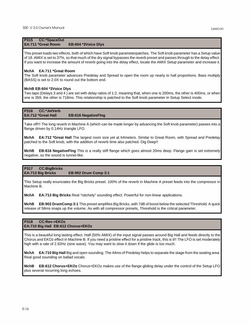
Lexicon300 V 3.0 Owner's Manual
5-16
P315 CC:*SpaceOutEA:711 *Great Room EB:604 *3Voice Dlys
This preset loads two effects, both of which have Soft knob parameterpatches. The Soft knob parameter has a Setup valueof 18. AMIX is set to 37%, so that much of the dry signal bypasses the reverb preset and passes through to the delay effect.If you want to increase the amount of reverb going into the delay effect, locate the AMIX Setup parameter and increase it.
MchA EA:711 *Great RoomThe Soft knob parameter advances Predelay and Spread to open the room up nearly to hall proportions. Bass multiply(BASS) is set to 2.0X to round out the bottom end.
MchB EB:604 *3Voice DlysTwo taps (Delays 3 and 4 ) are set with delay ratios of 1:2, meaning that, when one is 200ms, the other is 400ms, or whenone is 359, the other is 718ms. This relationship is patched to the Soft knob parameter in Setup Select mode.
P316 CC:*JetVerbEA:712 *Great Hall EB:616 NegativeFlng
Take off!!! The long reverb in Machine A (which can be made longer by advancing the Soft knob parameter) passes into aflange driven by 0.14Hz triangle LFO.
MchA EA:712 *Great Hall The largest room size yet at 64meters. Similar to Great Room, with Spread and Predelaypatched to the Soft knob, with the addition of reverb time also patched. Dig Deep!!
MchB EB:616 NegativeFlng This is a really stiff flange which goes almost 20ms deep. Flange gain is set extremelynegative, so the sound is tunnel-like.
P317 CC:BigBricksEA:713 Big Bricks EB:902 Drum Comp 3:1
This Setup really enunciates the Big Bricks preset. 100% of the reverb in Machine A preset feeds into the compressor inMachine B.
MchA EA:713 Big Bricks Real “ratchety” sounding effect. Powerful for non-linear applications.
MchB EB:902 DrumComp 3:1 This preset amplifies Big Bricks, with 7dB of boost below the selected Threshold. A quickrelease of 58ms snaps up the volume. As with all compressor presets, Threshold is the critical parameter.
P318 CC:Rev->EKOzEA:710 Big Hall EB:612 Chorus+EKOz
This is a beautiful long lasting effect. Half (50% AMIX) of the input signal passes around Big Hall and feeds directly to theChorus and EKOz effect in Machine B. If you need a pristine effect for a pristine track, this is it!! The LFO is set moderatelyhigh with a rate of 2.92Hz (sine wave). You may want to slow it down if the glide is too much.
MchA EA:710 Big Hall Big and open sounding. The 44ms of Predelay helps to separate the stage from the seating area.Real good sounding on ballad vocals.
MchB EB:612 Chorus+EKOz Chorus+EKOz makes use of the flange gliding delay under the control of the Setup LFOplus several recurring long echoes.

5-17
The Presets
P319 CC:Rev->KorusEA:706 Big & Short EB:609 Chorus
This Setup is a variation of the one above, except that it’s a shorter “close in” effect. There is also a different twist to thisSetup preset — L-Meter ballistics are patched to the AMIX Setup parameter. As the signal becomes stronger, AMIXbecomes progressively dryer, allowing more of the input signal to pass directly into the chorus effect. The LFO is set to1.98Hz with a triangle waveform. It controls the speed of the Glide in Machine B.
MchA EA:706 Big & Short This reverb effect is short, almost gated. Big room size set to 54.6M, and Rt set to 0.3 seconds.This preset really “opens up a sparse track.
MchB EB:609 Chorus This preset makes use of a small variation in the glide delay to modulate the sound. The glidemoves between 9.7ms and 11.8ms. Advancing the LFO to values near 1.50Hz to 2.0 Hz yields a nice chorusing effect. Thereare no other delay lines, but the output lines are channel-swapped such that the left input passes to the right output, andvice-versa.
P320 CC:Over!TopEA:605 OverTheTop1 EB:606 OverTheTop2
Use pre-fade. One flanger feeds the next. Very heavy duty. The input gain to the Setup is set to -4dB. This is to compensatefor the heavy amount of flange gain in both Machines. Since the LFO is in the setup domain, it drives both flange glide delaysin each Machine. !Remember the outputs of OverThe Top2 are reversed, so don’t drive yourself crazy trying to find reversedpatch cords!
MchA EA:605 OverTheTop1 This preset should be used pretty much through the box, i.e. patched to the LFO. Whenproperly modulated, the flange delay glides between 9.5ms and 18.7ms. The base delays are set to 10ms with a positivefeedback gain. Over the top cancellation occurs as the glide delay passes over the 10ms base delay.
MchB EB:606 OverTheTop2Similar to OverTheTop1, except the flange delay glides between 0.08 ms and 10.7ms. This flange delay is patched to theLFO. Base delays are set to 10ms with a negative amplifier gain. Over the top cancellation occurs as the glide delay passesover the 10ms base delay. The channel outputs are reversed such that the left input will pass through to the right outputand vice-versa.
P321 CC:GuitarXPEA:611 LFO:Pan&Faze EB:607 LFO:Faze Dlys
GuitarXP incorporates a left/right panning effect in Machine A into a modulating glide effect with added delays. The LFO(set to 0.20Hz with a triangle waveform) ties it all together. Here’re some suggestions: add some extra LDLY (Left delay)and RDLY (Right delay) to Machine B in Effect Edit. Go back to Setup Edit,and reduce BMIX to less than the preset 100%— say, to something like 45%, find the Cascade feedback parameter and add a small amount of feedback gain, eitherpositive or negative, then store it all in a Setup Register.
MchA EA:611 LFO:Pan&Faze This cool wavy preset should be run pre-fader with the Setup LFO at about .20Hz. Witha mono or stereosignal attached to both inputs, the acoustic effect is a slow rotation in phase. Thank goodness for CD’s.No record cutting lathe could handle this one. Clean compressed guitars are the best here.
MchB EB:607 LFO:FazeDlys Faze Dlys makes use of the LFO patched to the Flange Glide Delay(FDLY). The basedelays are set in different time domains: one side at 1.9ms with a feedforward gain; the other at 5.6 with a negative feedgain. As the Glide passes over each base delay, the phase of each gain is changed. In between, the output is a mixtureof each. A great effect on a ripping guitar solo.

Lexicon300 V 3.0 Owner's Manual
5-18
P322 CC:*EKO->FazeEA:805 Env*EKOShift EB:608 Env:Phazer
This pitch into Gliding delay Setup is great for the “rockers”. Use the Soft knob parameter to set the timing of the echoes inMachine A.
MchA EA:805 Env*EKOShift The Soft knob paramter controls the delay line length, and the L-Meter is negativelypatched to the feedback (FBK) parameter so that, when signal is present, delay feedback is reduced; when the signaldisappears, feedback is increased. This is a very interesting effect when the echo fits the beat of the music.
MchB EB:608 Env:Phazer This preset makes use of a patch between the envelope detector in the meters and the flangeglide delay. As signal becomes stronger, the glide delay drops in the time domain, eventually crossing the 5.2ms base delays.As audio signal strength lessens, the glide returns to its preset value of 10ms. Very good on vocals. To make this effect workproperly, be sure to drive the 300 to within 12dB of full scale (dBfs).
P323 CC: Verb->DownEA:720 Recital Hall EB:806 Echo Down
This cascade preset has the net effect of a stereo reverb field followed by delayed mono pitch shift which recirculatesdownward... in pitch. BMIX is set with a relatively low value of 38%. This means that most of the effect at the main outputis the reverb effect from Machine A. If you increase BMIX, more of the reverb will pass directly into the mono shift program.Bear in mind, this will cause the reverb to become more mono.
MchA EA:720 Recital Hall This medium large (44.5M) space opens sound sources beautifully. Made for string pads andvoice.
MchB EB:806 Echo Down 14 cents down with a 258ms recirculating delay line. In this setup, the reverb echoesdownward in pitch into the middle of the mix field ...Very Interesting.
P324 CC:*The SkyEA:804 Sky Down EB:610 *Sky Delays
This setup’s got a little bit of everything. A downward flanging pitch shifter cascading into a dual delay preset with many re-circulating delay clusters. The Soft knob parameter is patched to the left and right delays (LDLY and RDLY). This Setup alsoincorporates cascade feedback set to -36%. Don’t try to add too much more, you might take off your head. This is definitelya WOWIEE!!- ZOWIEEE!!! effect. The Soft knob parameter, which is stored with a value of 28, is patched to LDLY and RDLYin Machine B.
MchA EA:804 Sky Down This preset tunnels downward due to the liberal amount of delay feedback. If the effect is tooheavy, lower the feedback.
MchB EB:610 *Sky Delays This preset combines a bit of giding delay along with all sets of delays. Delays 1 and 2 areset short with feedback and “tuned” diffusion gains. Delays 3 and 4 are also set short and crossfeed into 2 and 1, respectively.There is a small amount of post delay (LDLY and RDLY), and these two post echoes are patched to the Soft knob. Use theSoft knob parameter to adjust the post delays to match the tempo. By itself, *Sky Delays is sort of a chorused cluster echo.Very similar to a bright resonant small room. Beautiful effect on stacked vocals. If you use this preset in a Cascade setupwhich has a small amount of Machine B feedback, the chorus will trail itself upand down in pitch. A very interesting twist.!Be CAREFUL. Do not use too much feedback ,as a runnaway feedback situaton may occur.

5-19
The Presets
P325 CC:SpinolaEA:609Chorus EB:011Panola
This is a sort of "retro" sounding audio effect. The Chorus preset passes into the fast panning Panola effect. Mix post-fader.Kind of like a rotating speaker — only different. The LFO is set to 8.00Hz, with a sine waveform.
MchA EA:609Chorus This preset makes use of a small variation in the glide delay to modulate the sound. The glidemoves between 9.7 and 11.8ms. If the LFO is advanced to values near 1.50Hz to 2.0Hz, a nice chorusing effect is achieved.There are no other delay lines, but the output lines are channel swapped such that the left input passes to the right outputand vice-versa.
MchB EB:011Panola This preset is a stereo adjust program with the Balance set to full left. The Balance parameter ispatched to the LFO. If loaded into a Setup which has the LFO running, Panola will cause the audio to move between theleft and right speakers.

Lexicon300 V 3.0 Owner's Manual
5-20
For your reference, all of the presets effects available in the split mode are listedand described below, in numerical order.
Split SetupEffect Descriptions
EP # Name Algorithm Description
601 *Dual Delays Dual Delays Baseline effect with the Soft knob patched to the last two delay linesin the signal path. Advancing the Soft knob parameter will cause thetwo post-delays to move in sync out to more than 2200ms.
602 Space Delays Dual Delays This preset incorporates a bit of left-right diffused delay along withsome small delay offset between left and right delay outputs. If theeffect is too strong you could try turning back the feedback levels forDelays 3 and 4.
603 *Pingo Pongo Dual Delays Ping - Pong delays bouncing back and forth. The Soft knobparameter controls the timing of the bounce.
604 *3Voice Dlys Dual Delays Two taps (Delay 3 and 4 ) are set with delay ratios of 1:2 —meaning when one is 200ms the other is 400ms, or when one is 359the other is 718ms. This relationship is patched to the Soft knob.
605 OverTheTop1 Dual Delays This preset should be used pretty much through the box, i.e. send ita pre-fader signal then mix only the returns. Flange Delay ispatched to the LFO. When properly modulated, the flange delayglides between 9.5 and 18.7ms. The base delays are set to 10mswith a positive feedback gain. Over the top cancellation occurs asthe glide delay passes over the 10ms base delay. Remember, theLFO is part of the Setup, so if you load the effect into a Setup wherethere is no LFO activity, the preset will sound “hollow” and resonant!
606 OverTheTop2 Dual Delays Similar to OverTheTop1 except the flange delay glides between0.08 and 10.7ms. Flange Delay is patched to the LFO. The basedelays are set to 10ms with a negative amplifier gain. Over the topcancellation occurs as the glide delay passes over the 10ms basedelay. The channel outputs are reversed such that the left input willpass through to the right output and vice-versa. Remember, theLFO is part of the Setup, so if you load the effect into a Setup wherethere is no LFO activity, the preset will sound “hollow” and resonant!
607 LFO:FazeDlys Dual Delays Faze Dlys also makes use of the LFO again to the Flange GlideDelay (FGLD). The base delays are set in different time domains;one side at 1.9ms with a feedforward gain and the other at 5.6 witha negative feed gain. As the glide passes over each base delay thephase of each gain is changed and in between the output is amixture of each. A great effect on a ripping guitar solo.
608 Env:Phazer Dual Delays This preset makes use of a patch between the envelope detector inthe meters and the Flange Glide Delay. As signal becomesstronger the glide delay drops in time domain eventually crossingthe 5.2 ms base delays. As audio signal strength lessens the glidereturns to its preset value of 10ms. Very good on vocals. To makethis effect work properly be sure to drive the 300 to within 12dB offull scale (dBfs).

5-21
The Presets
609 Chorus Dual Delays This preset makes use of a small variation in the glide delay tomodulate the sound. The glide moves between 9.7 and 11.8ms. Ifthe LFO is advanced to values near 1.50Hz to 2.0 Hz, a nicechorusing effect is achieved. There are no other delay lines, but theoutput lines are channel swapped such that the left input passes tothe right output and vice-versa.
610 *Sky Delays Dual Delays This preset combines a bit of giding delay along with all sets ofdelays. Delays 1 and 2 are set short with feedback and “tuned”diffusion gains. Delays 3 and 4 are also set short and crossfeedinto 2 and 1 respectively. There is a small amount of post delay(LDLY and RDLY) and these two post echoes are patched to theSoft knob. Use the Soft knob parameter to adjust the post delays tomatch the tempo. By itself, *Sky Delays is sort of a chorused clusterecho. Very similar to a bright resonant small room. Beautiful effecton stacked vocals. If you use this preset in a cascade setup whichhas some small amount of Machine B feedback, the chorus will trailitself upand down in pitch. Very interesting twist. Be careful not touse too much feedback to avoid runaway feedback.
611 LFO:Pan&Faze Dual Delays This cool wavy preset runs pre-fader with the Setup LFO at about20Hz LFO drifts back and forth with a stereo signal attached to it.With a mono signal attached to both inputs, the acoustic effect is aslow rotation in phase. Thank goodness for CD’s. No record cuttinglathe could handle this one. Clean compressed guitars are the besthere.
612 Chorus+EKOz Dual Delays This preset makes use of a gliding delay and several reccuringechoes.
613 *Wall Slaps Dual Delays Walls tied to the Soft knob parameter move outward. A smallamount of diffusion to smear the attack.
614 Env:Peak Dual Delays This preset is similar to an OverTheTop type effect, except theflange delay is patched to the meter ballistics.
615 NegativeFlng Dual Delays This is a really stiff flange, which goes almost 20ms deep. Flangegain is set extremely negative, so the sound is tunnel-like.

Lexicon300 V 3.0 Owner's Manual
5-22
EP # Name Algorithm Description
701 Chamber Split Chamber A great general purpose reverb tail. The size is set to 28.1M (thelargest value is 64M) so the density is rather close in. As you adjustsize the Rt value will also change. If you want to unlink this naturalphenomena, you can set the link value to unlink.
702 Key Chamber Split Chamber A nice “bloomy”-sounding reverb. The diffusion is set midway sothere is some good articulation at the begining of the reverbenvelope. Use this on most keyboards but those with a strong pointmay require a bit more diffusion.
703 Drum Chamber Split Chamber Good starting point for acoustic drums. This preset is slightly largerthan the standard chamber but has lass diffusion. RT is set to 1.0second at mid frequencies.
704 Drum Plate Split Chamber Tight and diffuse with all the “ring” you could possibly want.
705 Guitar Room Split Chamber This is a big wide sounding room for your guitars. For the heavyrock stuff you might consider panning “in” the returns. The room is alittle bottom heavy for additional warmth. Could also work well onvocals.
706 Big & Short Split Chamber This reverb effect is sort of gated. Big room size set to 54.6 metersand RT set to 0.3 seconds. This preset really “opens up" a sparsetrack.
707 “U” Chamber Split Chamber This preset is shaped liked an upside down “U” with the speaker ontop of the wall and a microphone on either side of the wall.
708 “L” Chamber Split Chamber “L” Chamber mimics the shape of a chamber by that letter. One sideis shorter than the other with the speaker closer to one side. A littlebigger than the “U” chamber.
709 Basement Split Chamber Tight and short. The room size 15.8 meters and the tonality is fairlyresonant sounding. Almost trashy sounding (low diffusion) and willcertainly get so if the RT is made longer.
710 Big Hall Split Chamber Big and open sounding. The 44ms of predelay help to separate thestage from the seating area. Real good sounding on ballad vocals.
711 *Great Room Split Chamber The Soft knob parameter advances the Predelay and spreads toopen the room up almost to hall proportions. Bass multiply is set to2.0X to round out the bottom end.
712 *Great Hall Split Chamber The largest room size yet at 64meters. Similar to Great Room withSpread and Predelay patched to the Soft knob with RT also patched.Dig Deep!!
713 Big Bricks Split Chamber Real “ratchety"-sounding effect. Powerful effect for non-lineapplications.
714 Joe’s B&G Split Chamber Live performances in Joe’s 14.6M Bar. Advance the Soft knobparameter and the room size grows into a Bar and Grill.
715 Joe’s Garage Split Chamber Two bays, no waiting. Small and bright.
716 Sizzle City Split Chamber Small and long type Plate. Very metallic reverb effect Great forcheap cymbals.

5-23
The Presets
717 *Drum Rooms Split Chamber Deep and narrow in shape. The Soft knob parameter makes theroom “shallower” and gated-sounding.
718 *BigBathroom Split Chamber Bright and clean. Generic WC. Great for solo stuff. or for addingliveness to a track. Soft knob draws out the Reverb Time.
719 *Delay Room Split Chamber This preset offers a nice room reference. The Soft knob parameteris patched to Predelay. Use this to make a bounce off the back walleffect without changing the Reverb Time.
720 Recital Hall Split Chamber This medium large (44.5M) space opens sound sources beautifully.Made for string pads and voice.
EP # Name Algorithm Description
801 Mono Shift Mono Pch Shift Baseline program with no pitch shift. Go to the glide parameter(GLD) in the Effect Edit mode to dial up the amount of pitch shiftingyou want.
802 Guitar Shift Mono Pch Shift This preset offers a heavy amount of micropitch shift(-21c) alongwith a small amount of recirculating predelay. Raunchy sounding onthe “beefy” guitars.
803 *Up Shift Mono Pch Shift Up Shift is a sweet sounding microshift up +7cents. There is a slight“chorus edge” due to a modest amount feedback around a 0msdelay line. The Soft knob parameter controls the delay line length.
804 Sky Down Mono Pch Shift This preset is tunnels downward due to the liberal amount of delayfeedback. If the effect is too heavy, dial back the feedback amount.
805 Env*EKOShift Mono Pch Shift The Soft knob parameter controls the delay line length and theL-Meter is negatively patched to the feedback (FBK) parameter suchthat when signal is present delay feedback is reduced, but when thesignal disappears, the feedback is increased. This is a veryinteresting effect when the echo fits the beat of the music.
806 Echo Down Mono Pch Shift 14 cents down with a 258ms recirculating delay line. This effectworks great either before or after a Reverb preset.
807 HalfStepsUp Mono Pch Shift Just what you would think.....
808 HalfStepsDn Mono Pch Shift Ditto....
809 Octave Down Mono Pch Shift Sounds good and deep.
810 Vocal Shift Mono Pch Shift This preset combines a short delay line recirculating around a-7 cent pitch shifter.
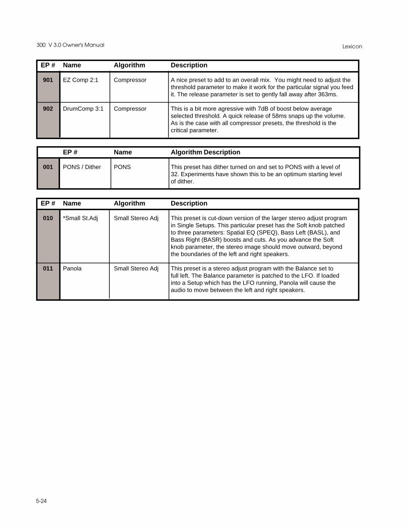
Lexicon300 V 3.0 Owner's Manual
5-24
EP # Name Algorithm Description
901 EZ Comp 2:1 Compressor A nice preset to add to an overall mix. You might need to adjust thethreshold parameter to make it work for the particular signal you feedit. The release parameter is set to gently fall away after 363ms.
902 DrumComp 3:1 Compressor This is a bit more agressive with 7dB of boost below averageselected threshold. A quick release of 58ms snaps up the volume.As is the case with all compressor presets, the threshold is thecritical parameter.
EP # Name Algorithm Description
001 PONS / Dither PONS This preset has dither turned on and set to PONS with a level of32. Experiments have shown this to be an optimum starting levelof dither.
EP # Name Algorithm Description
010 *Small St.Adj Small Stereo Adj This preset is cut-down version of the larger stereo adjust programin Single Setups. This particular preset has the Soft knob patchedto three parameters: Spatial EQ (SPEQ), Bass Left (BASL), andBass Right (BASR) boosts and cuts. As you advance the Softknob parameter, the stereo image should move outward, beyondthe boundaries of the left and right speakers.
011 Panola Small Stereo Adj This preset is a stereo adjust program with the Balance set tofull left. The Balance parameter is patched to the LFO. If loadedinto a Setup which has the LFO running, Panola will cause theaudio to move between the left and right speakers.

5-25
The Presets
Effect Presets Using the Random Hall Algorithm
P104 *ChurchRTIM SIZE ROLL PDLY4.0s 38.8M 4.0k 36m
RLVL TDCY BASS XOVRfull 2.9k 1.5X 0.9k
SPIN WAND SHAP SPRD40 10.1 82 226
DIFF LINK SHLF SIZE70 link off 38.8M
DLY1 DLY2 RTIM -32m 26m 4.0s -LVL1 LVL2 RLVL --8dB -7dB full -
DLY3 FBK3 DLY4 FBK4374m 12% 462m 12%LVL3 - LVL4 --14dB - -18dB -
MOD EDITSOURCE: SOFTKNOB
DEST SCALESize -49%
TDCY --30%LVL3 -14%LVL4 -10%
P105 * RoomsRTIM SIZE ROLL PDLY0.7s 19.1M 6.6k 0m
RLVL TDCY BASS XOVRfull 3.6k 1.2X 0.5k
SPIN WAND SHAP SPRD38 6258u 52 82
DIFF LINK SHLF SIZE65 link off 19.1M
DLY1 DLY2 RTIM -10m 20m 0.7s -LVL1 LVL2 RLVL --12dB -10dB full -
DLY3 FBK3 DLY4 FBK440m 0% 48m 0%LVL3 - LVL4 -
off - off -
MOD EDITSOURCE: SOFTKNOB
DEST SCALESize -25%
Effect PresetParameters
P101 Large HallRTIM SIZE ROLL PDLY2.0s 37.1M 0.9k 0m
RLVL TDCY BASS XOVRfull 3.6k 1.2X 0.2k
SPIN WAND SHAP SPRD38 10.1m 120 157
DIFF LINK SHLF SIZE65 link -6dB 37.1M
DLY1 DLY2 RTIM -14m 20m 2.03s -LVL1 LVL2 RLVL -
off off full -
DLY3 FBK3 DLY4 FBK440m 0% 48m 0%LVL3 - LVL4 -
off - off -
P102 Medium HallRTIM SIZE ROLL PDLY1.7s 29.3M 1.0k 0m
RLVL TDCY BASS XOVRfull 4.4k 1.2X 0.2k
SPIN WAND SHAP SPRD33 8016u 100 97
DIFF LINK SHLF SIZE68 link -6dB 29.3M
DLY1 DLY2 RTIM -14m 20m 1.7s -LVL1 LVL2 RLVL -
off off full -
DLY3 FBK3 DLY4 FBK440m 0% 48m 0%LVL3 - LVL4 -
off - off -
P103 Small HallRTIM SIZE ROLL PDLY1..1S 23.6M 1.3k 0mRLVL TDCY BASS XOVR
full 5.5k 1.2X 0.2k
SPIN WAND SHAP SPRD28 6762u 70 64
DIFF LINK SHLF SIZE65 link -6dB 23.6M
DLY1 DLY2 RTIM -8m 18m 1.1s -
LVL1 LVL2 RLVL -off off full -
DLY3 FBK3 DLY4 FBK444m 0% 34m 0%LVL3 - LVL4 -
off - off -
P106 RehursalRoomRTIM SIZE ROLL PDLY1.3s 15.2M 5.1k 0m
RLVL TDCY BASS XOVRfull 4.4k 0.4X 2.4k
SPIN WAND SHAP SPRD0 0u 124 65
DIFF LINK SHLF SIZE98 link off- 15.2M
DLY1 DLY2 RTIM -56m 60m 1.3s -LVL1 LVL2 RLVL -
off off -4dB -
DLY3 FBK3 DLY4 FBK40m 0% 0m 0%
LVL3 - LVL4 -off - -10dB -
MOD EDITSOURCE: SOFTKNOB
DEST SCALEPDLY +2.4%SPRD -63%SHAP -24%TDCY +16%
P107 *ChamberRTIM SIZE ROLL PDLY1.3s 25.3M 3.4k 2m
RLVL TDCY BASS XOVRfull 4.4k 1.5X 0.4k
SPIN WAND SHAP SPRD34 6258u 67 95
DIFF LINK SHLF SIZE79 link off 25.3M
DLY1 DLY2 RTIM -8m 20m 1.3s -
LVL1 LVL2 RLVL --7dB -7dB full -
DLY3 FBK3 DLY4 FBK440m 0% 48m 0%LVL3 - LVL4 -
off - off -
MOD EDITSOURCE: SOFTKNOB
DEST SCALESize -30%
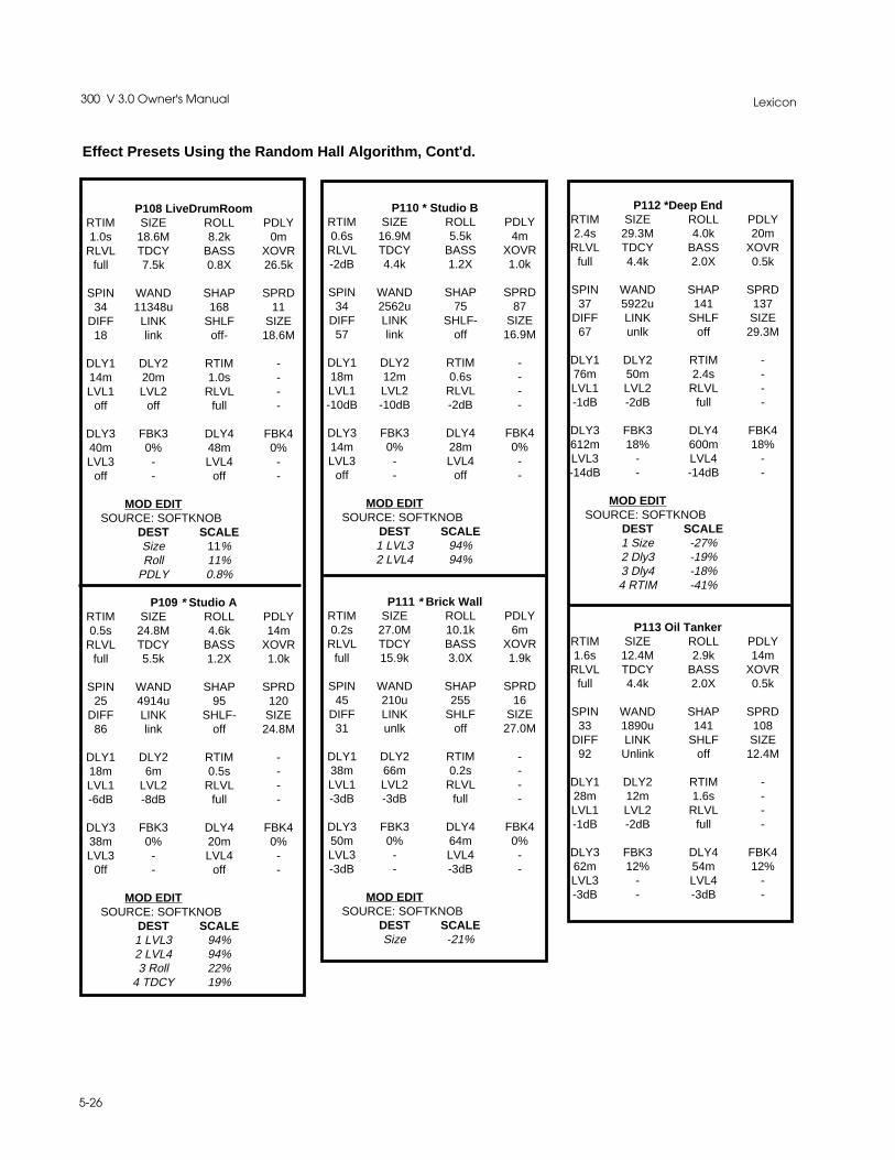
Lexicon300 V 3.0 Owner's Manual
5-26
P108 LiveDrumRoomRTIM SIZE ROLL PDLY1.0s 18.6M 8.2k 0m
RLVL TDCY BASS XOVRfull 7.5k 0.8X 26.5k
SPIN WAND SHAP SPRD34 11348u 168 11
DIFF LINK SHLF SIZE18 link off- 18.6M
DLY1 DLY2 RTIM -14m 20m 1.0s -LVL1 LVL2 RLVL -
off off full -
DLY3 FBK3 DLY4 FBK440m 0% 48m 0%LVL3 - LVL4 -
off - off -
MOD EDITSOURCE: SOFTKNOB
DEST SCALESize 11%Roll 11%
PDLY 0.8%
P109 * Studio ARTIM SIZE ROLL PDLY0.5s 24.8M 4.6k 14m
RLVL TDCY BASS XOVRfull 5.5k 1.2X 1.0k
SPIN WAND SHAP SPRD25 4914u 95 120
DIFF LINK SHLF- SIZE86 link off 24.8M
DLY1 DLY2 RTIM -18m 6m 0.5s -LVL1 LVL2 RLVL --6dB -8dB full -
DLY3 FBK3 DLY4 FBK438m 0% 20m 0%LVL3 - LVL4 -
0ff - off -
MOD EDITSOURCE: SOFTKNOB
DEST SCALE1 LVL3 94%2 LVL4 94%3 Roll 22%
4 TDCY 19%
Effect Presets Using the Random Hall Algorithm, Cont'd.
P112 *Deep EndRTIM SIZE ROLL PDLY2.4s 29.3M 4.0k 20m
RLVL TDCY BASS XOVRfull 4.4k 2.0X 0.5k
SPIN WAND SHAP SPRD37 5922u 141 137
DIFF LINK SHLF SIZE67 unlk off 29.3M
DLY1 DLY2 RTIM -76m 50m 2.4s -LVL1 LVL2 RLVL --1dB -2dB full -
DLY3 FBK3 DLY4 FBK4612m 18% 600m 18%LVL3 - LVL4 --14dB - -14dB -
MOD EDITSOURCE: SOFTKNOB
DEST SCALE1 Size -27%2 Dly3 -19%3 Dly4 -18%4 RTIM -41%
P113 Oil TankerRTIM SIZE ROLL PDLY1.6s 12.4M 2.9k 14m
RLVL TDCY BASS XOVRfull 4.4k 2.0X 0.5k
SPIN WAND SHAP SPRD33 1890u 141 108
DIFF LINK SHLF SIZE92 Unlink off 12.4M
DLY1 DLY2 RTIM -28m 12m 1.6s -LVL1 LVL2 RLVL --1dB -2dB full -
DLY3 FBK3 DLY4 FBK462m 12% 54m 12%LVL3 - LVL4 --3dB - -3dB -
P110 * Studio BRTIM SIZE ROLL PDLY0.6s 16.9M 5.5k 4m
RLVL TDCY BASS XOVR-2dB 4.4k 1.2X 1.0k
SPIN WAND SHAP SPRD34 2562u 75 87
DIFF LINK SHLF- SIZE57 link off 16.9M
DLY1 DLY2 RTIM -18m 12m 0.6s -LVL1 LVL2 RLVL --10dB -10dB -2dB -
DLY3 FBK3 DLY4 FBK414m 0% 28m 0%LVL3 - LVL4 -
off - off -
MOD EDITSOURCE: SOFTKNOB
DEST SCALE1 LVL3 94%2 LVL4 94%
P111 * Brick WallRTIM SIZE ROLL PDLY0.2s 27.0M 10.1k 6m
RLVL TDCY BASS XOVRfull 15.9k 3.0X 1.9k
SPIN WAND SHAP SPRD45 210u 255 16
DIFF LINK SHLF SIZE31 unlk off 27.0M
DLY1 DLY2 RTIM -38m 66m 0.2s -LVL1 LVL2 RLVL --3dB -3dB full -
DLY3 FBK3 DLY4 FBK450m 0% 64m 0%LVL3 - LVL4 --3dB - -3dB -
MOD EDITSOURCE: SOFTKNOB
DEST SCALESize -21%

5-27
The Presets
Effect Presets Using theRandom Hall Algorithm, Cont'd.
P114 *Synth HallRTIM SIZE ROLL PDLY3.7s 22.0M 4.8k 0m
RLVL TDCY BASS XOVRfull 5.5k 0.6X 0.4k
SPIN WAND SHAP SPRD30 147u 0 0
DIFF LINK SHLF SIZE99 link off 22.0M
DLY1 DLY2 RTIM -12m 16m 3.7s -LVL1 LVL2 RLVL -
off off full -
DLY3 FBK3 DLY4 FBK40m 0% 0m 0%
LVL3 - LVL4 -off - off
MOD EDITSOURCE: SOFTKNOB
DEST SCALEShape 47%SPRD 44%PDLY 7.1%Roll 16%
P115 Dance HallRTIM SIZE ROLL PDLY1.4s 20.3M 8.5k 44m
RLVL TDCY BASS XOVRfull 7.5k 1.2X 1.4k
SPIN WAND SHAP SPRD18 4410u 135 129
DIFF LINK SHLF SIZE98 link off 20.3M
DLY1 DLY2 RTIM -6m 22m 1.4s -
LVL1 LVL2 RLVL --4dB -4dB full -
DLY3 FBK3 DLY4 FBK440m 0% 48m 0%LVL3 - LVL4 -
off - off -
Effect Presets Using the Random Ambience Algorithm
P206 EarlyReflectlRTIM SIZE DIFF ROLL0.3s 8.5M 59 21.2k
RLVL DDLY PDLY -full 0m 0.1m -
SPIN WAND - -30 0u - -
P207 Lecture HallRTIM SIZE DIFF ROLL1.1s 24.8M 32 8.9k
RLVL DDLY PDLY --12dB 0m 27.7m -
SPIN WAND - -34 9450u - -
P208 *CarInteriorRTIM SIZE DIFF ROLL0.3s 4.5M 0 6.3k
RLVL DDLY PDLY -off 0m 0m -
SPIN WAND - -18 1008 - -
MOD EDITSOURCE: SOFTKNOB
DEST SCALESpin 60%
P209 Score StageRTIM SIZE DIFF ROLL2.1s 20.3M 94 4.4k
RLVL DDLY PDLY --4dB 0m 9.6m -
SPIN WAND - -9 6426u - -
P210 Gate It!!RTIM SIZE DIFF ROLL0.0s 14.1M 59 21.2k
RLVL DDLY PDLY -full 0m 0m -
SPIN WAND - -33 6426u - -
P201 * AmbienceRTIM SIZE DIFF ROLL2.0s 29.3M 75 3.6k
RLVL DDLY PDLY --14dB 0m 0m -
SPIN WAND - -30 7098 - -
MOD EDITSOURCE: SOFTKNOB
DEST SCALE1 Size -63%2 Spin 18%
P202 In A RoomRTIM SIZE DIFF ROLL0.9s 9.0M 79 5.5k
RLVL DDLY PDLY --7dB 0m 7.3m -
SPIN WAND - -15 63u - -
P203 StairwellRTIM SIZE DIFF ROLL3.6s 27M 99 6.3k
RLVL DDLY PDLY --4dB 0m 17.1m -
SPIN WAND - -0 0u - -
MOD EDITSOURCE: SOFTKNOB
DEST SCALESize -5.5%Roll -13%
PDLY -21%RTIM -2.4%
P204 *HangarRTIM SIZE DIFF ROLL6.6s 39.4M 34 5.5k
RLVL DDLY PDLY --8dB 56.5m 1m -
SPIN WAND - -33 7434u - -
MOD EDITSOURCE: SOFTKNOB
DEST SCALESize -25%
P205 Marble FoyerRTIM SIZE DIFF ROLL2.9s 19.7M 63 6.3k
RLVL DDLY PDLY --7dB 17.5m 0m -
SPIN WAND - -26 2730u - -

Lexicon300 V 3.0 Owner's Manual
5-28
P307 Bright PlateRTIM SIZE ROLL PDLY1.3s 23.1M 10.6k 0m
RLVL TDCY BASS XOVRfull 12.8k 1.0X 1.0k
RAND - SHAP SPRD0ff - 0 0
DIFF LINK - SIZE88 link - 23.1M
DLY1 DLY2 DLY3 DLY40m 0m 2m 14m
FBK1 FBK2 LVL3 LVL40% 0% -2dB -2dB
DLY5 FBK5 DLY6 FBK614m 0% 2m 0%LVL5 - LVL6 --2dB - -2dB -
P306 * Round PlateRTIM SIZE ROLL PDLY0.7s 27.6M 15.0k 0m
RLVL TDCY BASS XOVRfull 5.5k 2.0X 3.6k
RAND - SHAP SPRDoff - 0 0
DIFF LINK - SIZE99 link - 27.6M
DLY1 DLY2 DLY3 DLY4582m 592m 30m 38mFBK1 FBK2 LVL3 LVL40% 0% off off
DLY5 FBK5 DLY6 FBK618m 0% 10m 0%LVL5 - LVL6 --3dB - -3dB -
MOD EDITSOURCE: SOFTKNOB
DEST SCALE1 FBK1 -29%2 FBK2 -29%3 SIZE 100%4 SIZE 100%
P304 Perc PlateRTIM SIZE ROLL PDLY1.1s 16.3M 8.5k 0m
RLVL TDCY BASS XOVRfull 10.6k 0.8X 1.4k
RAND - SHAP SPRD77% - 15 29DIFF LINK - SIZE87 link - 16.3M
DLY1 DLY2 DLY3 DLY490m 92m 18m 8mFBK1 FBK2 LVL3 LVL40% 0% -4dB -4dB
DLY5 FBK5 DLY6 FBK68m 0% 16m 0%
LVL5 - LVL6 -off - off -
P305 Contem-PlateRTIM SIZE ROLL PDLY1.7s 29.8M 9.7k 0m
RLVL TDCY BASS XOVRfull 8.9k 0.8X 0.6k
RAND - SHAP SPRD22% - 22 50DIFF LINK - SIZE99 link - 29.8M
DLY1 DLY2 DLY3 DLY40m 0m 6m 22m
FBK1 FBK2 LVL3 LVL40% 0% -8dB -6dB
DLY5 FBK5 DLY6 FBK60m 0% 0m 0%
LVL5 - LVL6 -off - off -
P306 * EKO PlateRTIM SIZE ROLL PDLY1.5s 28.7M 8.5k 10m
RLVL TDCY BASS XOVR-4dB 6.3k 1.0X 1.0k
RAND - SHAP SPRD46% - 0 0DIFF LINK - SIZE67 link - 28.7M
DLY1 DLY2 DLY3 DLY4660m 628m 30m 34mFBK1 FBK2 LVL3 LVL443% -37% -4dB -4dB
DLY5 FBK5 DLY6 FBK654m 25% 28m 25%LVL5 - LVL6 --4dB - -4dB -
MOD EDITSOURCE: SOFTKNOB
DEST SCALE1 RTiM -24%2 Dly1 -27%3 Dly2 -29%
P301 *Rich PlateRTIM SIZE ROLL PDLY1.7s 24.2M 14.2k 0m
RLVL TDCY BASS XOVRfull 12.8k 1.0X 0.8k
RAND - SHAP SPRD82% - 16 31DIFF LINK - SIZE99 link - 24.2M
DLY1 DLY2 DLY3 DLY4500m 500m 30m 38mFBK1 FBK2 LVL3 LVL40% 0% off off
DLY5 FBK5 DLY6 FBK674 0% 250m 0%
LVL5 - LVL6 -off - off -
MOD EDITSOURCE: SOFTKNOB
DEST SCALE1 RTIM -33%
P302 Glossy PlateRTIM SIZE ROLL PDLY1.8s 20.3M flat 0m
RLVL TDCY BASS XOVRfull 21.2k 0.6X 0.2k
RAND - SHAP SPRD64% - 24 20DIFF LINK - SIZE99 link - 20.3M
DLY1 DLY2 DLY3 DLY490m 92m 30m 20mFBK1 FBK2 LVL3 LVL40% 0% full full
DLY5 FBK5 DLY6 FBK68m 0% 16m 0%
LVL5 - LVL6 --3dB - -3dB -
P303 Warm PlateRTIM SIZE ROLL PDLY1.2s 18.6M 7.5k 0m
RLVL TDCY BASS XOVRfull 8.9k 1.2X 2.5k
RAND - SHAP SPRDoff - 115 74
DIFF LINK - SIZE83 link - 18.6M
DLY1 DLY2 DLY3 DLY490m 92m 30m 20mFBK1 FBK2 LVL3 LVL40% 0% off off
DLY5 FBK5 DLY6 FBK68m 0% 16m 0%
LVL5 - LVL6 -off - off -
Effect Presets Using the Rich Plate Algorithm

5-29
The Presets
P407 *MultiEchoesMSTR BAL ROT DLAY0dB <0> <0> 0m
D-EM 11uS RFnS -off off +L+R -
BASS TREB LTRB RTRBflat flat flat flat
BXOV TXOV TXLR SPEQ0.5k 7.5k 12.2k flat
LDLY LFIN RDLY RFIN60m 434S 270m 436SLFBK Lfbk RFBK Rfbk45% -20% 28% -17%
MOD EDITSOURCE: SOFTKNOB
DEST SCALE1 DLAY 100%
P408 LFO PannerMSTR BAL ROT DLAY0dB L+78 <0> 0m
D-EM 11uS RFnS -off off +L+R -
BASS TREB LTRB RTRBflat flat flat flat
BXOV TXOV TXLR SPEQ0.5k 7.5k 12.2k flat
LDLY LFIN RDLY RFIN0m 0S 0m 0S
LFBK Lfbk RFBK Rfbk0% 0% 0% 0%
MOD EDITSOURCE: SOFTKNOB
DEST SCALELFO 100%
P410 TelephoneMSTR BAL ROT DLAY0dB <0> <0> 0m
D-EM 11uS RFnS -off off +L+R -
BASS TREB LTRB RTRB-15 +6.0 -16 cut
BXOV TXOV TXLR SPEQ1.4k 0.5k 6.6k flat
LDLY LFIN RDLY RFIN0m 0S 0m 0S
LFBK Lfbk RFBK Rfbk0% 0% 0% 0%
Effect Presets Using the Stereo Adjust Algorithm
P404 3 Frame DlyMSTR BAL ROT DLAY0dB <0> <0> 100m
D-EM 11uS RFnS -off off +L+R -
BASS TREB LTRB RTRBflat flat flat flat
BXOV TXOV TXLR SPEQ0.5k 7.5k 12.2k flat
LDLY LFIN RDLY RFIN0m 0S 0m 0S
LFBK Lfbk RFBK Rfbk0% 0% 0% 0%
P405 4 Frame DlyMSTR BAL ROT DLAY0dB <0> <0> 130m
D-EM 11uS RFnS -off off +L+R -
BASS TREB LTRB RTRBflat flat flat flat
BXOV TXOV TXLR SPEQ0.5k 7.5k 12.2k flat
LDLY LFIN RDLY RFIN0m 133S 0m 133S
LFBK Lfbk RFBK Rfbk0% 0% 0% 0%
P406 MS DecodeMSTR BAL ROT DLAY0dB L+0 R+67 0m
D-EM 11uS RFnS -off off +L+R -
BASS TREB LTRB RTRBflat flat flat flat
BXOV TXOV TXLR SPEQ0.5k 7.5k 12.2k flat
LDLY LFIN RDLY RFIN0m 0S 0m 0S
LFBK Lfbk RFBK Rfbk0% 0% 0% 0%
P401 Stereo AdjustMSTR BAL ROT DLAY0dB <0> <0> 0m
D-EM 11uS RFnS -off off +L+R -
BASS TREB LTRB RTRBflat flat flat flat
BXOV TXOV TXLR SPEQ0.5k 7.5k 12.2k flat
LDLY LFIN RDLY RFIN0m 0S 0m 0S
LFBK Lfbk RFBK Rfbk0% 0% 0% 0%
P402 Phase InvertMSTR BAL ROT DLAY0dB <0> <0> 0m
D-EM 11uS RFnS -off off +L-R -
BASS TREB LTRB RTRBflat flat flat flat
BXOV TXOV TXLR SPEQ0.5k 7.5k 12.2k flat
LDLY LFIN RDLY RFIN0m 0S 0m 0S
LFBK Lfbk RFBK Rfbk0% 0% 0% 0%
P403 2 Frame DlyMSTR BAL ROT DLAY0dB <0> <0> 60m
D-EM 11uS RFnS -off off +L+R -
BASS TREB LTRB RTRBflat flat flat flat
BXOV TXOV TXLR SPEQ0.5k 7.5k 12.2k flat
LDLY LFIN RDLY RFIN0m 282S 0m 282S
LFBK Lfbk RFBK Rfbk0% 0% 0% 0%
P404 2 Frame DlyMSTR BAL ROT DLAY0dB <0> <0> 60m
D-EM 11uS RFnS -off off +L+R -
BASS TREB LTRB RTRBflat flat flat flat
BXOV TXOV TXLR SPEQ0.5k 7.5k 12.2k flat
LDLY LFIN RDLY RFIN0m 282S 0m 282S
LFBK Lfbk RFBK Rfbk0% 0% 0% 0%

Lexicon300 V 3.0 Owner's Manual
5-30
Effect Presets Using the Stereo Pitch Shift Algorithm
P505 Bulkie RollMODE GLDL - GLDRMono 99% - 101%PCHL FINL PCHR FINR
Nul -14C Nul +13C
LDLY LFBK RDLY RFBK8m 18% 8m 18%
BNPS SYNC - -On On - -
P506 Heavy RollMODE GLDL - GLDRMono 99% - 101%PCHL FINL PCHR FINR
Nul -14C Nul +20C
LDLY LFBK RDLY RFBK50m 20% 60m 20%
BNPS SYNC - -On On - -
P507 *Going, GoingMODE GLDL - GLDR
Ster 112% - 112%PCHL FINL PCHR FINR+Ma2 +0C +Ma2 +0C
LDLY LFBK RDLY RFBK150m 60% 150m 60%BNPS SYNC - -
On On - -
MOD EDITSOURCE: SOFTKNOB
DEST SCALE1 LDly 69%2 RDly 69%
P508 Zorch!MODE GLDL - GLDRMono 111% - 87%PCHL FINL PCHR FINR+mi2 +81C -Ma2 -38C
LDLY LFBK RDLY RFBK38m 57% 76m 50%
BNPS SYNC - -On On - -
P501 Stereo ShiftMODE GLDL - GLDR
ster 100% - 100%PCHL FINL PCHR FINR
nul 0C nul 0C
LDLY LFBK RDLY RFBK32m 0% 32m 0%
BNPS SYNC - -on on - -
MOD EDITSOURCE: SOFTKNOB
DEST SCALE1 GLDL 100%
P502 Octave DownMODE GLDL - GLDR
ster 50% - 50%PCHL FINL PCHR FINR-Oct 0C -Oct 0C
LDLY LFBK RDLY RFBK30m 0% 30m 0%
BNPS SYNC - -On On - -
P503 Vox ChorusMODE GLDL - GLDRMono 100% - 99%PCHL FINL PCHR FINR
Nul -7C Nul -14C
LDLY LFBK RDLY RFBK16m 11% 26m 7%
BNPS SYNC - -On Off - -
P504 Pole FlangeMODE GLDL - GLDR
Ster 100% - 100%PCHL FINL PCHR FINR
Nul -7C Nul -7C
LDLY LFBK RDLY RFBK0m 46% 0m 46%
BNPS SYNC - -On On - -

5-31
The Presets
P603 *PingoPongoCC: FDLY LFBD RFBD
0.0m 0.0m 0.0mMchA LFLG RFLG
0% 0%
CC: DLY1 FBK1150m 30%
MchA DLY2 FBK2150m 40%
CC: APD1 APG14.8m 100
MchA APD2 APG28.6m 100
CC: DLY3 FBK30.0m 0%
MchA DLY4 FBK40.0m 0%
CC: LDLY LPAN75m L-CH
MchA RDLY RPAN0m R-CH
Patch#1 DLY1
Knob 0 0 80%#2 DLY2
Knob 0 0 80%#3 LDLY
Knob 0 0 40%
P604 *3VoiceDlysCC: FDLY LFBD RFBD
0.0m 0.0m 0.0mMchA LFLG RFLG
0% 0%
CC: DLY1 FBK10.0m 0%
MchA DLY2 FBK20.0m 0%
CC: APD1 APG10.0m 0
MchA APD2 APG20.0m 0
CC: DLY3 FBK3147m 40%
MchA DLY4 FBK4294m 32%
CC: LDLY LPAN18m L-CH
MchA RDLY RPAN18m R-CH
Patch#1 DLY3
Knob 0 0 40%#2DLY4Knob 0 0 80%
Effect Presets using the Dual Delays Algorithm
P601 *Dual DelaysCC: FDLY LFBD RFBD
0.0m 0.0m 0.0mMchA LFLG RFLG
0% 0%
CC: DLY1 FBK10.0m 0%
MchA DLY2 FBK20.0m 0%
CC: APD1 APG10.0m 0
MchA APD2 APG20.0m 0
CC: DLY3 FBK30.0m 0%
MchA DLY4 FBK40.0m 0%
CC: LDLY LPAN0.0m L-CH
MchA RDLY RPAN0.0m R-CH
Patch#1 LDLY
Knob 0 0 85%#2 RDLY
Knob 0 0 85%
P602 Space DelaysCC: FDLY LFBD RFBD
8.6m 0.0m 0.0mMchA LFLG RFLG
57% 86%
CC: DLY1 FBK1470m 22%
MchA DLY2 FBK2437m 23%
CC: APD1 APG14.0m 185
MchA APD2 APG27.4m 50
CC: DLY3 FBK3186m 28%
MchA DLY4 FBK4228m 36%
CC: LDLY LPAN36.2m L-CH
MchA RDLY RPAN18.9m R-CH
P605 OverTheTop1CC: FDLY LFBD RFBD
9.5m 10.0m 10.0mMchA LFLG RFLG
91% 91%
CC: DLY1 FBK10.0m 0%
MchA DLY2 FBK20.0m 0%
CC: APD1 APG10.0m 0
MchA APD2 APG20.0m 0
CC: DLY3 FBK30.0m 0%
MchA DLY4 FBK40.0m 0%
CC: LDLY LPAN0.0m L-CH
MchA RDLY RPAN0.0m R-CH
Patch#1 FDLY
LFO 0 49%
P606 OverTheTop2CC: FDLY LFBD RFBD
0.8m 10.0m 10.0mMchA LFLG RFLG
-85% -85%
CC: DLY1 FBK10.0m 0%
MchA DLY2 FBK20.0m 0%
CC: APD1 APG10.0m 0
MchA APD2 APG20.0m 0
CC: DLY3 FBK30.0m 0%
MchA DLY4 FBK40.0m 0%
CC: LDLY LPAN0.0m R-CH
MchA RDLY RPAN0.0m L-CH
Patch#1 FDLY
LFO 0 49%

Lexicon300 V 3.0 Owner's Manual
5-32
P611 LFO:Pan&FazeCC: FDLY LFBD RFBD
10.1m 3.5m 9.0mMchA LFLG RFLG
-99% 99%
CC: DLY1 FBK10.0m 0%
MchA DLY2 FBK20.0m 0%
CC: APD1 APG16.6m 0
MchA APD2 APG28.4m 0
CC: DLY3 FBK30.0m 0%
MchA DLY4 FBK40.0m 0%
CC: LDLY LPAN0.0m L-CH
MchA RDLY RPAN0.0m R-CH
Patch#1 FDLY
LFO 0 -33%#2 RPAN
LFO 0 100%#3 LPAN
LFO 0 100%
P612 Chorus+EKOzCC: FDLY LFBD RFBD
8.4m 0.0m 0.0mMchA LFLG RFLG
-37% -30%
CC: DLY1 FBK1411 15%
MchA DLY2 FBK2223m 20%
CC: APD1 APG14.9m 71
MchA APD2 APG27.1m 74
CC: DLY3 FBK3330m 32%
MchA DLY4 FBK4616m 22%
CC: LDLY LPAN16.6m L-CH
MchA RDLY RPAN31.7m R-CH
Patch#1 FDLY
LFO 5 7.5%
P609 ChorusCC: FDLY LFBD RFBD
9.7m 1.4m 19.4mMchA LFLG RFLG
19% 19%CC: DLY1 FBK1
0.0m 0%MchA DLY2 FBK2
0.0m 0%CC: APD1 APG1
0.0m 0MchA APD2 APG2
0.0m 0CC: DLY3 FBK3
0.0m 0%MchA DLY4 FBK4
0.0m 0%CC: LDLY LPAN
5.7m R-CHMchA RDLY RPAN
16.0m L-CH
Patch#1 FDLY
LFO 0 9.5%
P610 *Sky DelaysCC: FDLY LFBD RFBD
1.8m 5.8m 4.3mMchA LFLG RFLG
-28% 28%
CC: DLY1 FBK179.8m 22%
MchA DLY2 FBK228.7m -20%
CC: APD1 APG110.2m 47
MchA APD2 APG25.6m 36
CC: DLY3 FBK381.7m 40%
MchA DLY4 FBK456.0m -30%
CC: LDLY LPAN57.2m L-CH
MchA RDLY RPAN41.4m R-CH
Patch#1 LDLY
Knob 0 0 78%#2 RDLY
Knob 0 0 72%#3 FDLY
LFO 0 75%
P607 LFO:FazeDlysCC: FDLY LFBD RFBD
6.0m 1.9m 5.6mMchA LFLG RFLG
-99% 99%
CC: DLY1 FBK1382m 23%
MchA DLY2 FBK2366m 19%
CC: APD1 APG16.6m 164
MchA APD2 APG28.4m 152
CC: DLY3 FBK3149m 18%
MchA DLY4 FBK4130m 26%
CC: LDLY LPAN18.2m L-CH
MchA RDLY RPAN12.3m R-CH
Patch#1 FDLY
LFO 0 -22%
P608 Env:PhazerCC: FDLY LFBD RFBD
9.7m 5.2 5.2MchA LFLG RFLG
86% 86%
CC: DLY1 FBK10.0m 0%
MchA DLY2 FBK20.0m 0%
CC: APD1 APG16.6m 0
MchA APD2 APG28.4m 0
CC: DLY3 FBK30.0m 0%
MchA DLY4 FBK40.0m 0%
CC: LDLY LPAN0.0m L-CH
MchA RDLY RPAN0.0m R-CH
Patch#1 FDLY
L-Meter 0 -30%
Effect Presets using the Dual Delays Algorithm, Cont'd.

5-33
The Presets
Effect Presets using the Dual Delays Algorithm, Cont'd.
P613 *Wall SlapsCC: FDLY LFBD RFBD
0.0m 0.0m 0.0mMchA LFLG RFLG
0% 0%
CC: DLY1 FBK140.4m 31%
MchA DLY2 FBK257.4m 25%
CC: APD1 APG18.9m 74
MchA APD2 APG26.0m 83
CC: DLY3 FBK30.0m 0%
MchA DLY4 FBK40.0m 0%
CC: LDLY LPAN26.9m L-CH
MchA RDLY RPAN26.9m R-CH
Patch#1 DLY1
Knob 0 0 5.5.%#2 DLY2
Knob 0 0 7.1%
P614 Env:PeakCC: FDLY LFBD RFBD
6.2m 10.0m 11.5mMchA LFLG RFLG
87% 87%
CC: DLY1 FBK10m 0%
MchA DLY2 FBK20m 0%
CC: APD1 APG10m 0
MchA APD2 APG20m 0
CC: DLY3 FBK30.0m 0%
MchA DLY4 FBK40.0m 0%
CC: LDLY LPAN0m L-CH
MchA RDLY RPAN0m R-CH
Patch#1 FDLY
R-Meter 0 30%
P615 NegativeFlngCC: FDLY LFBD RFBD
18.5m 8.3m 8.7mMchA LFLG RFLG
-96% -96%
CC: DLY1 FBK10m 0%
MchA DLY2 FBK20m 0%
CC: APD1 APG10m 0
MchA APD2 APG20m 0
CC: DLY3 FBK30m 0%
MchA DLY4 FBK40m 0%
CC: LDLY LPAN0m R-CH
MchA RDLY RPAN0m L-CH
Patch#1 FDLY
LFO 0 -48%
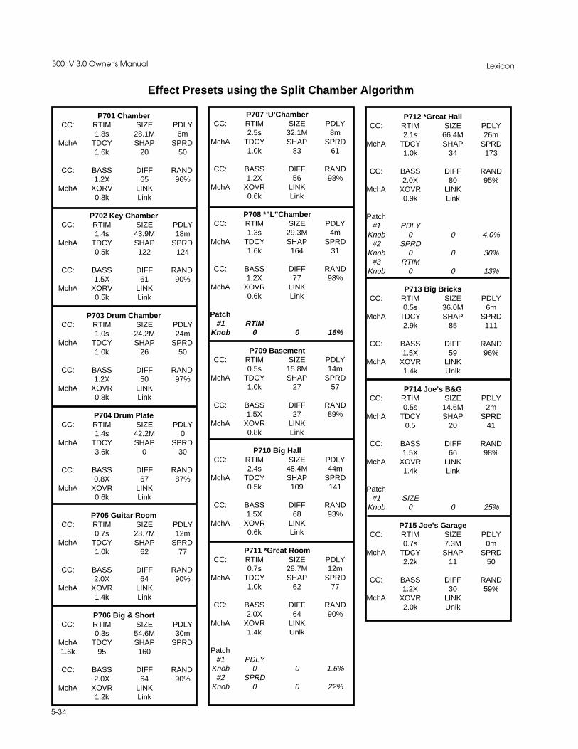
Lexicon300 V 3.0 Owner's Manual
5-34
P707 ‘U’ChamberCC: RTIM SIZE PDLY
2.5s 32.1M 8mMchA TDCY SHAP SPRD
1.0k 83 61
CC: BASS DIFF RAND1.2X 56 98%
MchA XOVR LINK0.6k Link
P708 *”L”ChamberCC: RTIM SIZE PDLY
1.3s 29.3M 4mMchA TDCY SHAP SPRD
1.6k 164 31
CC: BASS DIFF RAND1.2X 77 98%
MchA XOVR LINK0.6k Link
Patch#1 RTIM
Knob 0 0 16%
P709 BasementCC: RTIM SIZE PDLY
0.5s 15.8M 14mMchA TDCY SHAP SPRD
1.0k 27 57
CC: BASS DIFF RAND1.5X 27 89%
MchA XOVR LINK0.8k Link
P710 Big HallCC: RTIM SIZE PDLY
2.4s 48.4M 44mMchA TDCY SHAP SPRD
0.5k 109 141
CC: BASS DIFF RAND1.5X 68 93%
MchA XOVR LINK0.6k Link
P711 *Great RoomCC: RTIM SIZE PDLY
0.7s 28.7M 12mMchA TDCY SHAP SPRD
1.0k 62 77
CC: BASS DIFF RAND2.0X 64 90%
MchA XOVR LINK1.4k Unlk
Patch#1 PDLY
Knob 0 0 1.6%#2 SPRD
Knob 0 0 22%
P712 *Great HallCC: RTIM SIZE PDLY
2.1s 66.4M 26mMchA TDCY SHAP SPRD
1.0k 34 173
CC: BASS DIFF RAND2.0X 80 95%
MchA XOVR LINK0.9k Link
Patch#1 PDLY
Knob 0 0 4.0%#2 SPRD
Knob 0 0 30%#3 RTIM
Knob 0 0 13%
P713 Big BricksCC: RTIM SIZE PDLY
0.5s 36.0M 6mMchA TDCY SHAP SPRD
2.9k 85 111
CC: BASS DIFF RAND1.5X 59 96%
MchA XOVR LINK1.4k Unlk
P714 Joe’s B&GCC: RTIM SIZE PDLY
0.5s 14.6M 2mMchA TDCY SHAP SPRD
0.5 20 41
CC: BASS DIFF RAND1.5X 66 98%
MchA XOVR LINK1.4k Link
Patch#1 SIZE
Knob 0 0 25%
P715 Joe’s GarageCC: RTIM SIZE PDLY
0.7s 7.3M 0mMchA TDCY SHAP SPRD
2.2k 11 50
CC: BASS DIFF RAND1.2X 30 59%
MchA XOVR LINK2.0k Unlk
P701 ChamberCC: RTIM SIZE PDLY
1.8s 28.1M 6mMchA TDCY SHAP SPRD
1.6k 20 50
CC: BASS DIFF RAND1.2X 65 96%
MchA XORV LINK0.8k Link
P702 Key ChamberCC: RTIM SIZE PDLY
1.4s 43.9M 18mMchA TDCY SHAP SPRD
0,5k 122 124
CC: BASS DIFF RAND1.5X 61 90%
MchA XORV LINK0.5k Link
P703 Drum ChamberCC: RTIM SIZE PDLY
1.0s 24.2M 24mMchA TDCY SHAP SPRD
1.0k 26 50
CC: BASS DIFF RAND1.2X 50 97%
MchA XOVR LINK0.8k Link
P704 Drum PlateCC: RTIM SIZE PDLY
1.4s 42.2M 0MchA TDCY SHAP SPRD
3.6k 0 30
CC: BASS DIFF RAND0.8X 67 87%
MchA XOVR LINK0.6k Link
P705 Guitar RoomCC: RTIM SIZE PDLY
0.7s 28.7M 12mMchA TDCY SHAP SPRD
1.0k 62 77
CC: BASS DIFF RAND2.0X 64 90%
MchA XOVR LINK1.4k Link
P706 Big & ShortCC: RTIM SIZE PDLY
0.3s 54.6M 30mMchA TDCY SHAP SPRD1.6k 95 160
CC: BASS DIFF RAND2.0X 64 90%
MchA XOVR LINK1.2k Link
Effect Presets using the Split Chamber Algorithm

5-35
The Presets
P716 Sizzle CityCC: RTIM SIZE PDLY
2.6s 13.5M 0mMchA TDCY SHAP SPRD
10.6k 161 11
CC: BASS DIFF RAND0.4X 68 97%
MchA XOVR LINK1.9k Unlk
P717 *Drum RoomsCC: RTIM SIZE PDLY
1.1s 16.3M 16mMchA TDCY SHAP SPRD
3.6k 58 32
CC: BASS DIFF RAND1.5X 15 MAX
MchA XOVR LINK0.8k Link
Patch#1 XOVR
Knob 0 0 85%#2 SPRD
Knob 0 0 40%#3 RTIM
Knob 0 0 -16%
P718 *BigBathroomCC: RTIM SIZE PDLY
1.1s 18.0M 0mMchA TDCY SHAP SPRD
10.6k 205 68
CC: BASS DIFF RAND1.2X 44 30%
MchA XOVR LINK5.8k Unlk
Patch#1 RTIM
Knob 0 0 25%#2 TDCY
Knob 0 0 -30%
P719 *Delay RoomCC: RTIM SIZE PDLY
0.7s 33.2M 30mMchA TDCY SHAP SPRD
1.0k 138 78
CC: BASS DIFF RAND1.2X 65 96%
MchA XOVR LINK3.6k Unlk
Patch#1 PDLY
Knob 0 0 16%
Effect Presets using the Split Chamber Algorithm, Cont'd.
P720 Recital HallCC: RTIM SIZE PDLY
2.3s 44.5M 30mMchA TDCY SHAP SPRD
1.0k 125 59
CC: BASS DIFF RAND1.2X 60 96%
MchA XOVR LINK0.9k Link
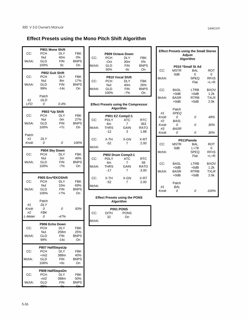
Lexicon300 V 3.0 Owner's Manual
5-36
P801 Mono ShiftCC: PCH DLY FBK
Nul 40m 0%MchA: GLD FIN BNPS
100% 0c On
P802 Guit ShiftCC: PCH DLY FBK
Nul 8m 17%MchA: GLD FIN BNPS
99% -14c On
Patch#1 GLD
LFO 0 0.4%
P803 *Up ShiftCC: PCH DLY FBK
Nul 0m 27%MchA: GLD FIN BNPS
100% +7c On
Patch#1 DLY
Knob 0 0 100%
P804 Sky DownCC: PCH DLY FBK
Nul 2m 49%MchA: GLD FIN BNPS
100% -7% On
P805 Env*EKOShiftCC: PCH DLY FBK
Nul 10m 69%MchA: GLD FIN BNPS
100% +7% On
Patch#1 DLY
Knob 0 0 93%#2 FBK
L-Meter 0 -47%
P806 Echo DownCC: PCH DLY FBK
Nul 258m 25%MchA: GLD FIN BNPS
99% -14c On
P807 HalfStepsUpCC: PCH DLY FBK
+mi2 388m 40%MchA: GLD FIN BNPS
106% +0c On
P808 HalfStepsDnCC: PCH DLY FBK
-mi2 388m 50%MchA: GLD FIN BNPS
95% -0c On
Effect Presets using the Small StereoAdjust
Algorithm
P010 *Small St AdCC: MSTR BAL ROT
0dB 0 0MchA: SPEQ RFnS
Flat +L+R
CC: BASL LTRB BXOV+0dB +0dB 1.2k
MchA: BASR RTRB TXLR+0dB +0dB 2.0k
Patch#1 SPEQ
Knob 0 0 49%#2 BASL
Knob 0 0 30%#3 BASR
Knob 0 0 30%
P011PanolaCC: MSTR BAL ROT
0dB L+78 0MchA: SPEQ RFnS
Flat +L+R
CC: BASL LTRB BXOV+0dB +0dB 1.2k
MchA: BASR RTRB TXLR+0dB +0dB 2.0k
Patch#1 BAL
Knob 0 0 100%
P809 Octave DownCC: PCH DLY FBK
-Oct 30m 0%MchA: GLD FIN BNPS
50% -0c On
P810 Vocal ShiftCC: PCH DLY FBK
Nul 40m 26%MchA: GLD FIN BNPS
100% -7% On
Effect Presets using the CompressorAlgorithm
P901 EZ Comp2:1CC: PDLY ATC RTC
6m 7 363MchA: THRS GAIN RATO
-12 3 1.88
CC: X-TH X-GN X-RT-52 7 2.00
MchA:
P902 Drum Comp3:1CC: PDLY ATC RTC
4m 7 58MchA: THRS GAIN RATO
-17 7 3.00
CC: X-TH X-GN X-RT-52 7 2.00
MchA:
Effect Presets using the PONSAlgorithm
P001 PONSCC: DITH PONS
32 OnMchA:
Effect Presets using the Mono Pitch Shift Algorithm

6-1
Time Code Operation
6Time CodeOperation

Lexicon300 V3.0 Owner's Manual
6-2
Using time code The 300 utilizes time code to trigger Setup and Effect changes. It can also usetime code to trigger parameter glides. In order for any of the time code functionsto work, a time code source must be plugged into the Time Code Input on the300 rear panel.
Time code is an electronic signal applied to tape or film which identifies eachindividual video frame. The ability to uniquely identify any frame provides areference system for fast and accurate location of any point on the tape. Thisreferencing system maintains its accuracy regardless of changes in playback orediting equipment, allowing precise synchronization of an entire editing system.
Time code identifies each video frame by assigning it a unique “address”.Frames are sequentially identified by hour, minute, second, and frame. Forexample, a typical timecode address appears as:
09 : 42 : 31 : 07 hours minutes seconds frames
As each frame is advanced, the time code address is increased by one frame“count”. Because the time code signal is locked to advancing video frames, bothadvance at exactly the same rate.
In the USA, there are two standard frame rates, one for black and white(monochrome) and one for color.
Monochromatic video runs at a rate of 30 frames per second. If a black and whiteTV program is measured by time code, the program length, time code display,and clock time will all be in synchronization. Color video signals run at a rate of29.97 frames per second, and clocking a one-hour color program at 30 framesper second will result in a time discrepancy of 3.6 seconds (or 108 frames). Inorder to correct this discrepancy, a version of time code called SMPTE DropFrame was developed.
SMPTE Drop Frame Time Code, as its name implies, eliminates frame ad-dresses from the Time Code each hour to allow matching of time code and clocktime. Specifically, frame addresses .00 and .01 are eliminated at the end of everyminute in an hour, except for minutes: 00,10,20,30,40 and 50. For example,00.00.59.29 advances to the number 00.01.00.02. In Drop Frame mode, theframe numbers .00 and .01 do not exist, except for minutes 00, 10, 20, 30,40 and 50. Since Drop Frame time code eliminates only frame addresses, theactual video is unaffected. Color video frames continue to progress at the rateof 29.97 per second. Any calculations of program length based on Drop Frametime code will, therefore, agree with standard clock time.
The 300 reads time code in the following formats:
SMPTE Standard time code, compatible with a monochromatic frame rate of 30frames per second
SMPTE Standard Drop Frame time code, compatible with a color frame rate of29.97 frames per second
Compatible with the European broadcast standard frame rate of 25 frames persecond
Compatible with frame rates of 24 frames per second.
SMPTE NON-DROP
SMPTE DROP FRAME
EBU
FILM

6-3
Time Code Operation
The 300 allows you to use time code (in any of the recognized formats) to triggerSetup, Effect, and parameter changes.
Up to 50 time code entries can be made on an Event List. Time codes can beentered via the numeric keypad, they can be "snapped" on the fly while time codeis running, or they can be selected with the soft knob.
To access the Event List simply press the front panel CONTROL button to enterControl mode, then use the Page Down button to step to the Event List display:
The Event List
Using time code toinitiate programchanges
Pressing this button enables/disables the Event List
Pressing one of these buttons se-lects a control page for the EventList
Pressing the second button from the right on the top row allows you to chooseto have a Timecode Event list enabled (ON) or disabled (OFF).
Pressing any of the bottom row of buttons selects a page of controls for the itemdisplayed directly above that button. Four pages are available for: addition ofevents to the list (ADD), deletion of items from the list (DEL), modification ofentries (EDIT), and "on the fly" insertion of items to the list (SNAP).
The 300 automatically sorts the Event List based on the time code addresses.If you add a new event it will be placed on the list at the appropriate place, andother entries will move in position. If you delete an entry, the remaining entrieswill retain their relative positions, but will move up one position.
Event List: OFF VIEW
ADD DEL EDIT SNAP

Lexicon300 V3.0 Owner's Manual
6-4
Snapping events
The number displayed in the upper left portion of the display indicates the eventnumber which you are about to snap. Simply press the key directly below"SNAP" wherever you want effect changes to happen. This will assign thosetime code addresses to the Event List.
The upper right portion of the display shows running time code. The lower lineof the display shows the time code of the most recently snapped entry, andallows you to clear the most recently snapped time code.
Time code formats are indicated as follows:
SV valid SMPTE Non-DropSDV valid SMPTE Drop FrameE-V valid EBUF-V valid Film
V indicates valid time code
Editing the Event List
The easiest way to develop a list in the 300 is to “SNAP” entries into the list. Touse the snap function, select OFF and turn the Soft knob to enable time code(ON). Locate the source machine to the beginning of the section you want toexperiment with. Give yourself about a 5 second preroll and “roll tape”. Now,press SNAP. The display should show rolling time code.
#01 _ _ _ _ 00 : 00 : 00 : 00
SNAP CLR 00 : 00 : 00 : 00
Edit #01 00 : 00 : 00 : 00
* *: New Event
Editing the list includes trimming snapped time codes, choosing the type ofautomation change, and selecting the event. The EDIT function also allows youto enter time code numbers directly into the list rather than snapping them. Toedit the event list, press the key directly below “EDIT”. The display will show:
Pressing the key directly above “#01” allows you to use the Soft knob to scrollthrough the Event List to select the event number you want to edit. You willobviously want to start with number one.

6-5
Time Code Operation
Press the key directly beneath “**”. Use the Soft knob to select the automationtype. Turn the Soft knob clockwise or counterclockwise to cause the letter S toappear.
The first entry must be a Setup (S). Other available types of Automation are:Setup changes (S)Effect changes Mach A (EA)Effect changes Mach B (EB) — only available if a “split” setup is runningParameter Glide Mach A (PA)Parameter Glide Mach B (PB) — only available if a “split” setup is runningParameter Glide Setup (PS)
Now, press the key under “P101”. You can now use the Soft knob to scrollthrough the entire list of setups, including any Setup registers which you mighthave stored. (Remember, the first entry must be a Setup.) Once you decidewhich Setup you want to start the list, press STORE. Your first event has all thenessessary elements: a time code address, the type of automaton change, andthe event to which it changes.
To move on to edit #2, press the key directly above “01”, then turn the Soft knobone “tick”.
Once you’ve got the list edited, and want to test a portion of it, press CNTRL. Thswill bring you back to the main time code menu. Locate the time code sourcemachine to the top of the production piece. Give yourself a 5 second preroll.
*NOTE: Your first Event (Edit #1) should occur before first picture or music. Youmay have to trim edit the first event to reflect this — After all, you really don’t wantthe 300 cueing up the first Setup while music or dialog is passing through the box.
From Edit mode, select the 8-digit time code number by pressing either of the twokeys above the time code entry. Use the Soft knob to increase or decrease thetime code value. Usually, when first using time code automation, your first eventwill need to be trimmed up several seconds to allow the first Setup to load beforeaudio, as expalined above. Turn the Soft knob counter-clockwise. When thecorrect number is displayed, press STORE.
Press CNTRL to return to the main time code menu. Press VIEW. If you’ve givenyourself the correct “pre-roll”, roll tape. The 300 should display time code and allsubsequent events which you have programmed into the Event List.
Trimming Time Codesin the Event List

Lexicon300 V3.0 Owner's Manual
6-6
Parameter glides can be a verypoweful feature. When you select a parameterglide (PA,PB, or PS) as type of automation change, the display will update anddisplay three entries; Parameter Selection (RTIM, PDLY, DLY1,FBK1...), finalparameter value (12.5s, 125m, 225m, 45%...), and the frame duration (25Fr) ofthe glide. The keys beneath each display entry allow you to select the functionfor Soft knob programming of the parameter glides.
All parameter glides are based on the current Setup and effect which loaded.
Example:Let’s say at the end of a scene, we want the Reverb Time to increase from itspreset value to 15 seconds. We want this glide to take 100 frames. At the sametime, we want the Input parameter to glide from its Setup value to OFF over thesame amount of time.
Suppose the current Setup and Effect is Dance Hall, then all of the parametersin the Setup and effect can Be glided.
The Event List up to the glide might look something like this:
ProgrammingParameter Glides
Edit #01 00 : 59 : 27 : 00
S: Large Hall
Edit #02 01 : 00 : 15 : 00
S: Dance Hall
Edit #03 01 : 00 : 21 : 07
**: New Event
You will need to make a copy of event 03 (because you want 2 parameter glides)into the list, then edit both entries.

6-7
Time Code Operation
From the main time code menu, select “ADD”. Now select the edit event numberby pressing the key directly above “#”. Use the Soft knob to selet “#3”, then pressSTORE. This makes a complete copy of event # 3 and places it into slot #4. Notethat Event #3 and Event #4 now have the same time code adress.
PRESS CNTRL to return to the main time code menu.
Press EDIT, then select Edit #3. Now, press the key directly below “**” and usethe Soft knob to program PA:(parameter,Machine A).
Press the next button to the right to use the Soft knob to program the actualparameter. Turn the Soft knob until the “RTIM” is displayed.
Press the next button to the right to use the Soft knob to select the final reverbtime. Adjust the value as close to 15 seconds as possible.
Finally, press the next button to the right. Turn the Soft knob clockwise to enterframe duration values. (100 Fr will equal approximately 3 seconds.)
Press STORE. Event #3 should look like this:
Edit #03 01 : 00 : 21 : 05
PA: RTIM->14.1s 100Fr
Press the key directly above “#”, and repeat the above steps so that the displaylooks like this:
Edit #04 01 : 00 : 21 : 05
PS: ALVL->Off 100Fr
Parameter glides which have been programmed into the Event List will beviewed singly, as the event happens. If you are VIEWing two or more glideswhich happen to be programmed for the same time code (as in the exampleabove), only the last entry will be displayed.

Lexicon300 V3.0 Owner's Manual
6-8
All parameter glides are based on the effect loaded in the list immediatelypreceding the glide. For example, let’s say that Medium Hall is Event Edit #4 andEvent Edit #5 specifies PA RTIM moving to a value of 3.8s, with a duration of 007Frames.
Q What happens if you change Event #4 from Medium Hall to Vox Chorus?
Things to ConsiderAbout Glides
Edit #04 00 : 59 : 27 : 00
S: VoxChorus
Edit #05 01 : 00 : 21 : 05
PA: GLD-> +Ma4 100Fr
A Event #5 is now being driven by an algorithm which does not have RTIM asa selectable parameter and which cannot, therefore, have a final parametervalue. New values will be automatically placed there based on the selectedalgorithm’s available parameters.
The proper thing to do is to delete Event #5.

6-9
Time Code Operation
Adding an eventOnce you have created an Event List, you can also modify it by adding effectchanges. Select ADD. The display will show:
The ADD function is used in two different ways. To duplicate an event, press thebutton directly above the Event number field and use the Soft knob to scroll tothe event that you want to copy. When you press STORE, the event will becopied. (The copy will be placed directly after the original on the list.) To edit theevent effect, return to the main Time Code menu (by pressing CONTROL), thenpress the button directly above "EDIT".
The second way to use the ADD function allows you to edit an existing event andadd the edited version as a new event in the list. To do this, press the buttondirectly above the event number, and use the Soft knob to scroll to the event youwant to start with. Now select the effect number, or the time code field, bypressing the button directly above these display choices, and change the valuesas needed. Each time you alter a time code entry, press ENTER. When you havemade all the changes you want, press STORE and the modified events will beadded to the list.
To delete an entry from the Event List, select DEL. The display will show:
Add #XX (Event no.) 00 : 00 : 00 : 00
* * : Setup name or "No Event"
Del #XX 00 : 00 : 00 : 00
* * : Setup name or "No Event"
Selecting #XX allows soft knob selection from among the Event List entrynumbers (1-50). The time code associated with the event number is displayedto the right. Press the key directly above "Del" to delete any event number fromthe list. Note that if an entry number is deleted from the list, all subsequent entrieswill move up on the list.
The Event List can be transferred via MIDI data dump via the MIDI Control pagein Control Mode.
Deleting an event
Dumping the list toMIDI storage devices

Lexicon300 V3.0 Owner's Manual
6-10
Event Effect# Time Code # Name Comment
1 : : :2 : : :3 : : :4 : : :5 : : :6 : : :7 : : :8 : : :9 : : :
10 : : :11 : : :12 : : :13 : : :14 : : :15 : : :16 : : :17 : : :18 : : :19 : : :20 : : :21 : : :22 : : :23 : : :24 : : :25 : : :26 : : :27 : : :28 : : :29 : : :30 : : :31 : : :32 : : :33 : : :34 : : :35 : : :36 : : :37 : : :38 : : :39 : : :40 : : :41 : : :42 : : :43 : : :44 : : :45 : : :46 : : :47 : : :48 : : :49 : : :50 : : :
This page may be reproduced as needed for recording any Event List you create.
300 Event List

7-1
MIDI Operation
7MIDI Operation
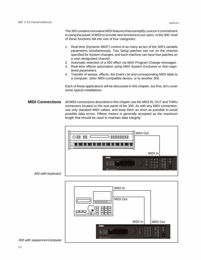
Lexicon300 V 3.0 Owner's Manual
7-2
The 300 contains innovative MIDI features that exemplify Lexicon's commitmentto using the power of MIDI to provide new functions to our users. In the 300 mostof these functions fall into one of four categories:
1. Real-time (Dynamic MIDI®) control of as many as ten of the 300's variableparameters simultaneously. Two Setup patches can run on the channelspecified for System changes, and each machine can have four patches ona user-designated channel.
2. Automatic selection of a 300 effect via MIDI Program Change messages.3. Real-time effects automation using MIDI System Exclusive or Non-regis-
tered parameters.4. Transfer of setups, effects, the Event List and corresponding MIDI table to
a computer, other MIDI-compatible device, or to another 300.
Each of these applications will be discussed in this chapter, but first, let's coversome typical installations.
All MIDI connections described in this chapter use the MIDI IN, OUT and THRUconnectors located on the rear panel of the 300. As with any MIDI connection,use only standard MIDI cables, and keep them as short as possible to avoidpossible data errors. Fifteen meters is generally accepted as the maximumlength that should be used to maintain data integrity.
300 with sequencer/computer
MIDI Connections
300 DIGITAL EFFECTS SYSTEM
MIDI
48 kHz44.1 kHz32 kHz
CONTROL
UP
PAGE
DOWN
7 8 9
4 5 6
1 2 3
— 0ENTER
PAGE
SETUP
SELECT
MACH
STORE
VALUE
SETUP
EDIT
EFFECT
EDIT
MOD
EDIT
BYPASS
A
BYPASS
B
POWER
LEVEL
MIDI In
MIDI Out
MIDI In MIDI Out
300 DIGITAL EFFECTS SYSTEM
MIDI
48 kHz44.1 kHz32 kHz
CONTROL
UP
PAGE
DOWN
7 8 9
4 5 6
1 2 3
— 0ENTER
PAGE
SETUP
SELECT
MACH
STORE
VALUE
SETUP
EDIT
EFFECT
EDIT
MOD
EDIT
BYPASS
A
BYPASS
B
POWER
LEVEL
MIDI Out
MIDI In
300 with keyboard
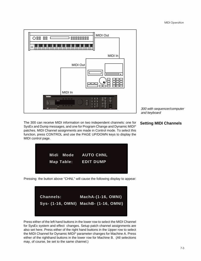
7-3
MIDI Operation
300 DIGITAL EFFECTS SYSTEM
MIDI
48 kHz44.1 kHz32 kHz
CONTROL
UP
PAGE
DOWN
7 8 9
4 5 6
1 2 3
— 0ENTER
PAGE
SETUP
SELECT
MACH
STORE
VALUE
SETUP
EDIT
EFFECT
EDIT
MOD
EDIT
BYPASS
A
BYPASS
B
POWER
LEVEL
MIDI Out
MIDI In
MIDI Out
MIDI In
300 with sequencer/computerand keyboard
The 300 can receive MIDI information on two independent channels: one forSysEx and Dump messages, and one for Program Change and Dynamic MIDI®
patches. MIDI Channel assignments are made in Control mode. To select thisfunction, press CONTROL and use the PAGE UP/DOWN keys to display theMIDI control page.
Setting MIDI Channels
Midi Mode AUTO CHNL
Map Table: EDIT DUMP
Pressing the button above "CHNL" will cause the following display to appear:
Channels: MachA-(1-16, OMNI)
Sys- (1-16, OMNI) MachB- (1-16, OMNI)
Press either of the left hand buttons in the lower row to select the MIDI Channelfor SysEx system and effect changes. Setup patch channel assignments arealso set here. Press either of the right hand buttons in the Upper row to selectthe MIDI Channel for Dynamic MIDI® parameter changes for Machine A. Presseither of the righthand buttons in the lower row for Machine B. (All selectionsmay, of course, be set to the same channel.)
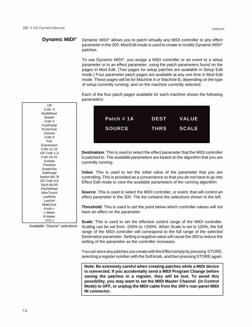
Lexicon300 V 3.0 Owner's Manual
7-4
Dynamic MIDI® Dynamic MIDI® allows you to patch virtually any MIDI controller to any effectparameter in the 300. Mod Edit mode is used to create or modify Dynamic MIDI®
patches.
To use Dynamic MIDI®, you assign a MIDI controller or an event to a setupparameter or to an effect parameter, using the patch parameters found on thepages in Mod Edit. (Two pages for setup patches are available in Setup Editmode.) Four parameter patch pages are available at any one time in Mod Editmode. These pages will be for Machine A or Machine B, depending on the typeof setup currently running, and on the machine currently selected.
Each of the four patch pages available for each machine shows the followingparameters:
OffCntlr- 0
ModWheelBreathCntlr-3
FootPedalPortaTime
VolumeCntlr-9
PanExpressionCntlr-12-15
GP Cntlr-1-4Cntlr-20-31
SustainPortaSw
SostenSwSoftPedal
Switch-68-79GP Cntlr-5-8Sitch-84-95PitchWheelAfterTouchLastNoteLastVel
MidiClockKnob->L-MeterR-MeterLFO-1
Available "Source" selections
Patch # 1A DEST VALUE
SOURCE THRS SCALE
Destination: This is used to select the effect parameter that the MIDI controlleris patched to. The available parameters are based on the algorithm that you arecurrently running.
Value: This is used to set the initial value of the parameter that you arecontrolling. This is provided as a convenience so that you do not have to go intoEffect Edit mode to view the available parameters of the running algorithm.
Source: This is used to select the MIDI controller, or event, that will control aneffect parameter in the 300. The list contains the selections shown to the left.
Threshold: This is used to set the point below which controller values will nothave an effect on the parameter.
Scale: This is used to set the effective control range of the MIDI controller.Scaling can be set from -200% to +200%. When Scale is set to 100%, the fullrange of the MIDI controller will correspond to the full range of the selectedDestination parameter. Setting a negative value will cause the 300 to reduce thesetting of the parameter as the controller increases.
You can store any patches you create with the Effect simply by pressing STORE,selecting a register number with the Soft knob, and then pressing STORE again.
Note: Be extremely careful when creating patches while a MIDI deviceis connected. If you accidentally send a MIDI Program Change beforesaving the patches in a register, they will be lost. To avoid thispossibility, you may want to set the MIDI Master Channel (in ControlMode) to OFF, or unplug the MIDI cable from the 300's rear-panel MIDIIN connector.

7-5
MIDI Operation
Using MIDI ProgramChange messageswith the 300
Editing the MIDI Table
MIDI Table mode
The 300 provides two different methods for using MIDI Program Changemessages. These functions are accessed in Control mode (selected by pressingCONTROL). From Control mode, use the PAGE UP/DOWN keys to select theMIDI Control page and press the key directly beneath "EDIT".
MIDI Table mode has three selections: OFF, FIX and MAP.
OFF sets the 300 to ignore all incoming Program Change messages.
If you are in the FIX mode, and are transmitting on the System channel, ProgramChange messages 0-99 will select 300 Setup Presets P1-P100; ProgramChange messages 100-127 will select the first 28 Setup Registers (R1-R28).Note that R29-R50 are not accessible to the MIDI Program Change mechanism.Setup changes will take precedence over Effect changes.
In FIX mode, if you are transmitting on channels assigned to Machine A and Bwhich are different from the System channel number, Setup changes will beignored. For each Machine, Program Change messages 0-99 will select EffectPresets P1-P100; Program Change messages 100-127 will select Effect Reg-isters R1-R28. Only effects which are legal for the setup will be selected. Illegaleffects will be ignored (the currently running effect will not change.) An errormessage will be displayed.
You will quickly discover that a fixed relationship between MIDI ProgramChanges and the 300's preset and register numbers is not very convenient.Changing the presets in a synth, or the registers in the 300, is not all that easywhen you have to arrange everything so that MIDI Program Changes have thedesired effect. To solve this problem, the 300 has a corresponding map tablewhich is used when the MIDI Table mode is set to MAP. In this mode, programchanges are transmitted on the System channel you have assigned. Setups,effects for Machine A and effects for Machine B can be mapped to any programchange message. Dealing with MIDI Program Changes becomes much easiersince you can completely rearrange the relationship of MIDI Program Changenumbers to the 300's registers and presets in minutes.
To assign Program Change messages to presets or setup registers, call up theMIDI Control page (from Control mode), and press the button directly below"EDIT".
Press either the first or second button on the top line, and use the Soft knob toselect the MIDI Program Change number you want to use. The third button onthe top line allows you to select S (Setup), EA (Effect A) or EB (Effect B). Therightmost button allows Soft knob selection of the setup or effect preset orregister number you want loaded by the Program Change number displayed onthe top line. Continue this procedure until the table contains all of the entries youneed.
Map:(1-128) -> S or E(AorB) #
Ch _ _ 1: preset or reg name
Lexicon300 V 3.0 Owner's Manual
7-6
Real-time MIDIEffects Automation
The 300 can be automated in a number of different ways, depending on yourapplications, and on the capabilities of your MIDI sequencer.
The six major categories of MIDI Automation are:
1. Using the 300's System Exclusive transmissions to record and play individ-ual parameter changes.
2. Using the 300's Non-Registered Parameter transmissions to record andplay individual parmeter changes.
3. Using MIDI Program Change messages to load Setups or Effects.4. Using MIDI Controller information and Dynamic MIDI® patches to record and
play parameter changes.5. Using the 300's System Exclusive or Non-Registered Parameter messages
that are the result of Dynamic MIDI® patches. This allows you to control,record, and play as many as five of the 300's variable parameters simulta-neously.
6. Controlling multiple 300s from a single master 300.
When using the 300's Automation capabilities, it is good practice to put the 300on a different MIDI Channel from those used by other equipment in your system.This avoids the possibility of the 300 responding to commands that aren't reallyintended for it.
The 300 will transmit System Exclusive or Non-Registered Parameter mes-sages as you vary any of the available parameters if this function is assigned inautomation mode. As you turn the Soft knob to vary one of the 300's effectparameters, MIDI data in the selected output format will be transmitted from the300's rear panel MIDI OUT connector as a Program Change. (All parametervalues are sent when the effect itself is changed.) This information can berecorded on your sequencer.
To set the automation mode, use the MIDI Control page in Control mode. Pressthe key under "AUTO", and use the Soft knob to select either "SysEx" or "Non-registered Params". There is also an "OFF" setting to prevent unwanted MIDItransmissions.
Once you have selected an automation mode, simply put your sequencer intoRecord, and change the 300's parameters to get the sounds you want. When youplay the sequence back, the 300 will respond to the recorded information just asit was recorded.
Note: The choice between SysEx or Non-Registered Parameters is determinedby your sequencer's capabilities, and your current utilization of its availablefunctions. With a bit of experimentation, and taking into consideration other MIDIdata you need to record, you can find the best combination for your equipment.
Note: Program Change messages are transmitted over the PARAM MIDIchannel, regardless of automation mode.
Using Real-time SysExand Non-Registered
Parameters
7-7
MIDI Operation
Some sequencers cannot record SysEx or Non-Registered Parameter informa-tion. In this case, you can use Dynamic MIDI® patches and record the MIDIController information used to get the real-time effect changes you want. Simplycreate the patches you want, and record the Controller information on yoursequencer. When the sequence is played back, the 300's Dynamic MIDI®
patches will respond to the recorded Controller commands.
This type of operation gives the best of all the 300's MIDI capabilities. Aspreviously described, create the patches you want. Set the 300 to one of theAutomation modes. Put your sequencer into Record, and use the MIDI Control-lers to create the effect parameter changes you need. As you change the effectparameters, the 300 will transmit information to your sequencer in the format youhave chosen (System Exclusive or Non-registered Parameters). This allows youto control and record as many as five parameters simultaneously. Again, whenyou play back the sequence, the 300 will respond just as the changes wererecorded.
In applications that require more than one 300 to work together, you can use one300 as a master, and slave as many 300s as you need to the master. This is doneby connecting the MIDI OUT of the master machine to the MIDI IN of the firstslave, then connecting the MIDI THRU of the first slave to the next slave, and soon.
Set the Automation mode on all machines to the same setting, and make surethat all machines are operating on the same MIDI Channel.
To see the results, select an effect from the master machine, then put all of themachines in Effect Edit mode — displaying the same page. When you turn thesoft knob on the master machine, all of the slaves will respond to the command.Note that, even if the displays are set to different pages on the various slavemachines, the parameter changes are still taking place.
Note: If master and slave machines have different input sources, i.e. a mix ofanalog and digital, effect changes will not work in SysEx and Non-RegisteredParameter modes.
Using Dynamic MIDI®
to transmit and receiveMIDI Controller Information
Using SysEx andDynamic MIDI®
Patches
Controlling Multiple300s

Lexicon300 V 3.0 Owner's Manual
7-8
Go to the MIDI page in Control mode and select "DUMP": The following displaywill appear:
MIDI Dumps of CurrentSetup, Event List,
MIDI Table, andAll Registers
Dump: ALL REGISTERS
Bulk Dump Dly: 2ms
Pressing any of the buttons in the top row will allow Soft knob selection of the typeof dump you want: All Registers, Current Setup, MIDI Map Table, or MTC EventList.
Pressing any of the buttons on the bottom row allow Softknob selection of pre-dump delay of 2ms, 50ms, 100ms or 200ms.
Once you have made the selections you want here, press STORE to send thisMIDI information. Please note that some dumps will take longer than others,depending on the amount of information to be passed.

8-1
Troubleshooting
8Troubleshooting

Lexicon300 V 3.0 Owner's Manual
8-2
Troubleshooting This chapter is intended primarily to help you recognize some common errorstates which can be corrected from the 300 front panel, or by simple means suchas cable replacement. Any error states which are not covered here should bereferred to your local dealer for service by a qualified technician.
In a low-voltage, or "brown-out" condition, the 300 will freeze in its current state.None of the controls will have any effect. When power returns to a normal levelthe unit will reset itself as though it had just been powered on. If the unit doesnot reset itself, turn the power OFF, then ON to resume normal operation.
Temperature extremes may cause the 300 to exhibit unpredictable behavior. Ifthe unit as been subjected to temperatures below 32°F (0°C) or above 95°F(35°C), it should be turned off and allowed to return to normal temperaturebefore use. The unit may be damaged by exposure to temperatures below -22°F(-30°C) or above 167°F (75°C), or by exposure to humidity in excess of 95%. Ifa unit exposed to such conditions fails to operate after it returns to a normaloperating temperature, contact your local service representative.
The 300 doesn't respond to MIDI Program Changes.Check the PARAM MIDI channel on the MIDI Control page in Control mode andcheck the Table Mode setting on the same page. The Table Mode should be setto FIX or TABLE. Also check MIDI In/Out connections between the units.
The 300 doesn't respond to Controller messages when using DynamicMIDI®.Check the PARAM MIDI Channel number on the MIDI Control page in Controlmode and check the patches in MOD Edit mode. Also check MIDI In/Outconnections between the units.
The 300 doesn't respond to SysEx commands.Check the SYSTEM MIDI Channel on the MIDI Control page in Control mode.
The 300 does not send MIDI parameter changes.Check the Automation mode on the MIDI Control page in Control mode. Thisshould be set to SYS EX or NON-REGISTERED PARAMS.
Low Voltage
Overheating
Common MIDIProblems

8-3
Troubleshooting
The 300 does not change effects to incoming time code.Check your cable connections and the setting of the Event List mode in Controlmode. Also check the signal level of the incoming time code. If it is too low, the300 may not respond.
The 300 will not lock to the incoming time code.Check the signal level of the incoming time code. If the level is too high or too low,the 300 may not lock to the signal. Also check the wiring of the time code cable.The time code input on the 300 is electronically balanced and, if the cable is notwired with this in mind, the 300 may not lock to the signal.
The 300 changes effects too late.Trim the time code values using the Edit function on the Time Code Event Listpage in Control mode.
The 300 will not lock onto an incoming digital signal.Check the cables that you are using. If the signal is coming in through the RCAconector, cable length must be kept to a minimum. If you are using the XLR input,remember that this is a transformer-balanced input, and the cable must be wiredwith this in mind. DO NOT USE ANALOG AUDIO CABLE TO CONNECTDIGITAL AUDIO.
When using the ANA+DIG input mode, there is no audio output.If you are using this mode and you are not sending a digital signal to the 300,audio may not pass through the system. To correct this, choose the ANALOGmode, or enter Effect Edit mode and turn the digital input level all the way down.
The meters do not show any incoming signal.The meters may be set to read the wrong inputs. Use the Meter page in SetupEdit mode to select the inputs you are using.
Common Time CodeProblems
Common DigitalInterfacing Problems
9-1
MIDI Implementation Data
9MIDIImplementationChart
MIDI Implementation Details are available to assist experienced programmersin developing software for use with the 300. These can be obtained from yourdealer, or directly from Lexicon. Request: Model 300 MIDI ImplementationDetails.

Lexicon300 V 3.0 Owner's Manual
9-2
Version: 3.0
MIDI Implementation Chart
Mode 1: OMNI ON, POLY Mode 2: OMNI ON, MONO O : YesMode 3: OMNI OFF, POLY Mode 4: OMNI OFF, MONO X : No
Lexicon 300Digital Effects System
Function Transmitted Recognized Remarks
Basic Default 1 1 Mach A, Mach B, andChannel Channel 1-16, OMNI 1-16, OMNI System on separate
channels; Memorized
Mode DefaulltMessages Mode 1, 3Altered
Note X 0 - 127 Used as controllerNumber True Voice
Velocity Note ON X O v=1-127 Used as controllerNote OFF X X
After Keys X XTouch Channels X X
Pitch Bender X O MSB only
Control 0-95 X OX 0-99 Controllers canChange be patched to
control effectsparameters
96 OX OX Data Increment97 OX OX Data Decrement98 OX O N-RPN99 OX O N-RPN
Program O O 0 - 127Change True # O 0 - 127
System Exclusive O O
System :Song Pos X X:Song Sel X X
Common :Tune X X
System :Clock X O as ControllerReal Time :Commands X X
Aux :Local ON/OFF X XMessages :All Notes OFF X X
:Active Sense X X:Reset X X
Notes If Channel is set to OFF, 300 will not recognize any messages

10-1
Specifications
10300 Specifications
Lexicon300 V 3.0 Owner's Manual
10-2
300 Specifications
Balanced XLR, pin 2 "high"
75Ω
-2dBu to +18dBu
48kHz sample rate: 10Hz to 21.5kHz, +0.2dB44.1kHz sample rate: 10Hz to 20kHz, +0.2dB32kHz sample rate: 10Hz to 14.5kHz, +0.2dB
+5 degrees, 10Hz to 20kHz
(Frequency Independent) From Digital Input to Analog Output: 1.8mS
90dB maximum, 10Hz to 20kHz
100dB minimum, A weighted
0.01% maximum, 10Hz to 20kHz
0.01% maximum
90dB minimum
15µs (+0.9µs) and 50µs (+3µs)
20dB in 0.1dB increments
Unless otherwise specified, specifications presume 48kHz sample rate, Emphasis off,Gain switch at 0dB, and Gain Control at unity (0dB)
Dynamic Range
Pre-emphasis
Balanced XLR, pin 2 "high"
50kΩ, unbalanced; 100kΩ, balanced
Gain switch in 0dB position: +2dBu minimum; +20dBu maximumGain switch in +16dB position: -14dBu minimum; +4dBu maximum
DC to 2kHz: 60dB minimum; 2kHz to 20kHz: 40dB minimum
48kHz sample rate: 10Hz to 21.5kHz, +0.2dB44.1kHz sample rate: 10Hz to 20kHz, +0.2dB32kHz sample rate: 10Hz to 14.5kHz, +0.2dB
+5 degrees, 10Hz to 20kHz
(Frequency Independent) From Analog Input to Digital Output: 0.75mS
80dB maximum, 10Hz to 20kHz
90dB minimum, A-weighted
0.01% maximum, 10Hz to 20kHz
0.01% maximum
90dB minimum
15µs (+0.9µs) and 50µs (+3µs)
20dB in 0.1dB incrementsGain Control
SMPTE IntermodulationDistortion
Total Harmonic Distortion
Signal to Noise Ratio
Crosstalk
Delay
Phase Linearity
Frequency Response
Common Mode Rejection
Full Scale Input Level
Input Impedance
Input Channels (2)
Audio Input and A/DConversion
D/A Conversion andAnalog Output
Output Channels (2)
Output Impedance
Full Scale Output Level
Frequency Response
Phase Linearity
Delay
Crosstalk
Signal-to-Noise Ratio
Total Harmonic Distortion
SMPTE IntermodulationDistortion
Dynamic Range
De-emphasis
Gain Control
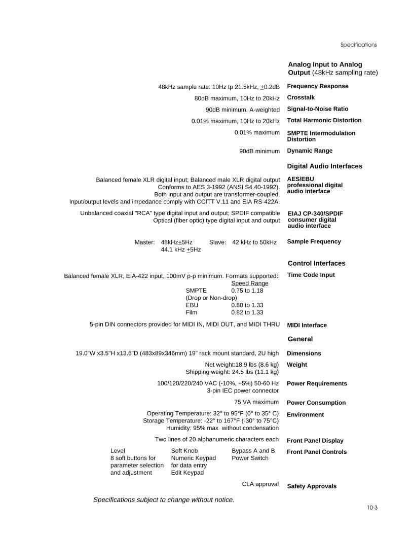
10-3
Specifications
Analog Input to AnalogOutput (48kHz sampling rate)
48kHz sample rate: 10Hz tp 21.5kHz, +0.2dB
80dB maximum, 10Hz to 20kHz
90dB minimum, A-weighted
0.01% maximum, 10Hz to 20kHz
0.01% maximum
90dB minimum
Frequency Response
Crosstalk
Signal-to-Noise Ratio
Total Harmonic Distortion
SMPTE IntermodulationDistortion
Dynamic Range
Balanced female XLR digital input; Balanced male XLR digital outputConforms to AES 3-1992 (ANSI S4.40-1992).
Both input and output are transformer-coupled.Input/output levels and impedance comply with CCITT V.11 and EIA RS-422A.
Unbalanced coaxial "RCA" type digital input and output; SPDIF compatibleOptical (fiber optic) type digital input and output
Master: 48kHz+5Hz Slave: 42 kHz to 50kHz44.1 kHz +5Hz
Digital Audio Interfaces
AES/EBUprofessional digitalaudio interface
Sample Frequency
EIAJ CP-340/SPDIFconsumer digitalaudio interface
Balanced female XLR, EIA-422 input, 100mV p-p minimum. Formats supported::Speed Range
SMPTE 0.75 to 1.18(Drop or Non-drop)EBU 0.80 to 1.33Film 0.82 to 1.33
5-pin DIN connectors provided for MIDI IN, MIDI OUT, and MIDI THRU
Control Interfaces
Time Code Input
MIDI Interface
General
19.0"W x3.5"H x13.6"D (483x89x346mm) 19" rack mount standard, 2U high
Net weight:18.9 lbs (8.6 kg)Shipping weight: 24.5 lbs (11.1 kg)
100/120/220/240 VAC (-10%, +5%) 50-60 Hz3-pin IEC power connector
75 VA maximum
Operating Temperature: 32° to 95°F (0° to 35° C)Storage Temperature: -22° to 167°F (-30° to 75°C)
Humidity: 95% max without condensation
Two lines of 20 alphanumeric characters each
Level Soft Knob Bypass A and B8 soft buttons for Numeric Keypad Power Switchparameter selection for data entryand adjustment Edit Keypad
CLA approval
Specifications subject to change without notice.
Dimensions
Weight
Power Requirements
Power Consumption
Environment
Front Panel Display
Front Panel Controls
Safety Approvals

Lexicon Part #070-09678 Rev. 2
Lexicon Inc.3 Oak ParkBedford MA 01730-1441Telephone 617-280-0300Fax 617-280-0940