digital imaging and remote sensing laboratory automatic tie-point and wire-frame generation from...
Post on 22-Dec-2015
220 views
TRANSCRIPT

Digital Imaging and Remote Sensing Laboratory
Automatic Tie-Point and Wire-frame Generation From
Oblique Aerial Imagery
Seth Weith-GlushkoAdvisor: Carl Salvaggio
Research ProposalNovember 7, 2003
Digital Imaging and Remote Sensing Laboratory
Table of Contents
•The Problem•Specific Aims•Proposed Solution
•A description of the individual transforms and algorithms used to make up the proposed algorithms
•Methods•Timetable•Budget•References

Digital Imaging and Remote Sensing Laboratory
The Problem
•Using photogrammetric techniques, tie matching algorithms and bundle adjustment algorithms, it is possible to create a 3D model using a series of images of an object•These images must be around an axis (for objects) or ortho-rectified (for landscapes) for the algorithms to work•We want to be able to use oblique imagery for input into the algorithms
•By using oblique imagery, more pixels are available to describe the features of a 3D object than would be in an ortho-rectified image
Digital Imaging and Remote Sensing Laboratory
Specific Aims
•Current algorithms only work on ortho-graphic (for tie-points) and axial imagery (for wire-frame generation)•The goal is to draw from both photogrammetry and computer graphics to develop two algorithms which can work in unison
•A tie-point algorithm that works on oblique imagery•A bundle adjustment algorithm that can use oblique imagery
•In the future, this algorithm would become part of a suite of algorithms that could generate an accurate 3D model of scene independent of the type of imagery used

Digital Imaging and Remote Sensing Laboratory
Proposed Solution
•The algorithm below relies heavily on the use of INS (Inertial Navigational System) data•The input would be a series of oblique images made around a common area•The output would be a matrix of matching points and a file using a common 3D format
Image ProcessingOrtho-rectification
Transform
Input:A series of obliqueimages around a
common area•Histogram processingConverts an
oblique image into an ortho-rectified
image

Digital Imaging and Remote Sensing Laboratory
Proposed Solution
Definition of PointsPoint matching
algorithmGeometric Transform
Use the Laplacian of Gaussian (LoG) filter to find points of high frequency
(i.e. edges)
Use point distance comparison, point scale comparison and point angle
comparison to find matching points
Using matched points, generate a
geometric transformation and use registration as
indicator of “goodness” of
points

Digital Imaging and Remote Sensing Laboratory
Proposed Solution
InverseGeometricTransform
InverseOrthorectification
Transform
Bundle AdjustmentAlgorithm
Perform an inverse geometric
transformation using previous transformation
matrix
Convert the orthorectified
image back into its original oblique
form
Using pairs of matched points,
define points in 3D space
Output:Matrix containing
matched pairs between images

Digital Imaging and Remote Sensing Laboratory
Proposed Solution
Interface with3D System
Using software libraries and
defined 3D points, generate an output
file
Output:3D wire-frame
mesh of a scene

Digital Imaging and Remote Sensing Laboratory
Ortho-rectification Transform
•The ortho-rectification transform converts an oblique image into an ortho-rectified (flat) image by means of a linear equation•There are four unknowns. We can use the fiducial points of an image as the four points we need to solve for the constants
1
1
33
222
33
111
ybxa
cybxaY
ybxa
cybxaX
Digital Imaging and Remote Sensing Laboratory
Image Processing
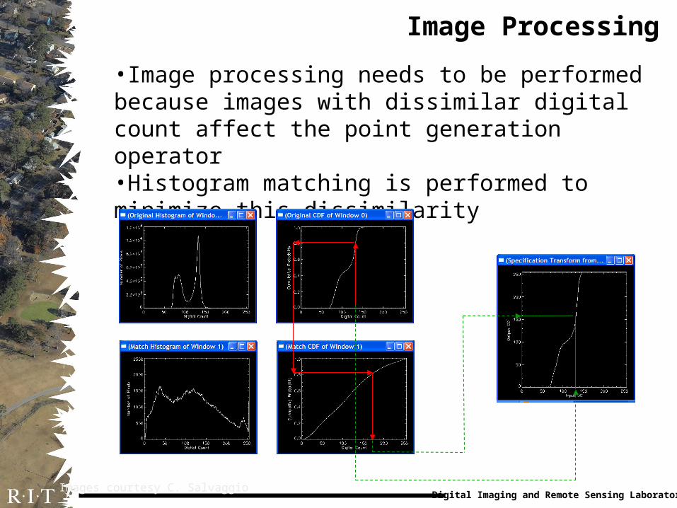
•Image processing needs to be performed because images with dissimilar digital count affect the point generation operator•Histogram matching is performed to minimize this dissimilarity
Images courtesy C. Salvaggio
Digital Imaging and Remote Sensing Laboratory
Definition of Points
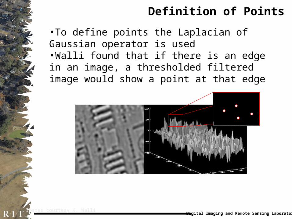
•To define points the Laplacian of Gaussian operator is used•Walli found that if there is an edge in an image, a thresholded filtered image would show a point at that edge
Images courtesy K. Walli

Digital Imaging and Remote Sensing Laboratory
Point Matching Algorithms
•To match defined points, three algorithms are primarily used: pixel distance match, scale match, angle match•Another matching criteria is LoG maxima similarity
25%

Digital Imaging and Remote Sensing Laboratory
Pixel Distance Match
•This algorithm works by comparing distances between pixels in a matrix
1 2 3 4
1
2
3
4
1 2 3 4
1
2
3
4
Distance=
1
2
3
1
2 3
2 2
1 2 1 2d x x y y
2 22 1 2 4 5d
123
0231
2205
3350
123
0251
2203
3530
# Same Elements:232
Digital Imaging and Remote Sensing Laboratory
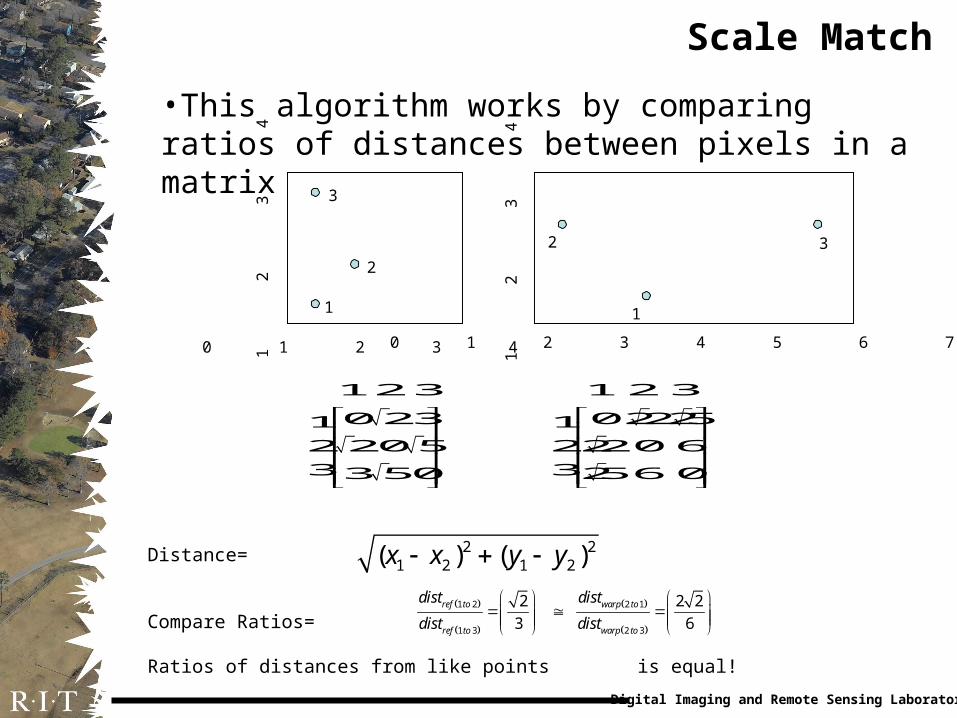
Scale Match
•This algorithm works by comparing ratios of distances between pixels in a matrix
0 1 2 3 4
1
2
3
4
0 1 2 3 4 5 6 7
1
2
3
4
Distance=
Compare Ratios=
Ratios of distances from like points is equal!
1
2
3
1
2 3
12 3
0 231
2 20 5
33 50
1 2 3
022251
2220 6
3256 0
1 2 2 1
1 3 2 3
2 2 2
3 6ref to warp to
ref to warp to
dist dist
dist dist
2 21 2 1 2( ) ( )x x y y
Digital Imaging and Remote Sensing Laboratory
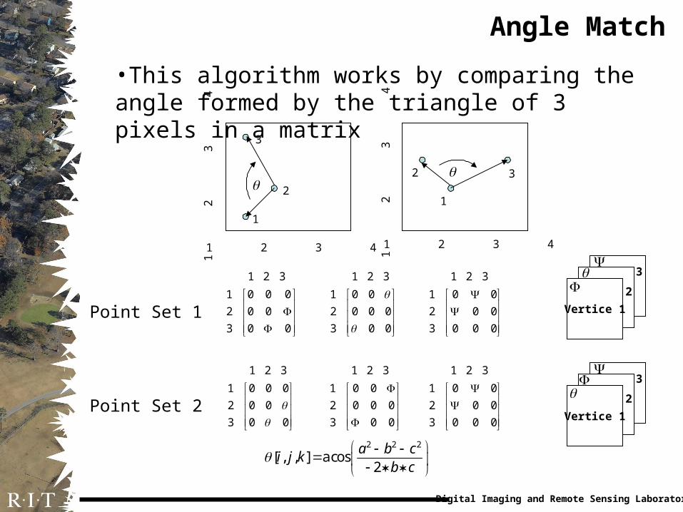
Angle Match
•This algorithm works by comparing the angle formed by the triangle of 3 pixels in a matrix
1 2 3 4
1
2
3
4
1 2 3 4
1
2
3
4
1
2
3
1
2 3
2 2 2
[ , , ] a cos2
a b ci j k
b c
1 2 3
1 0 0 0
2 0 0
3 0 0
1 2 3
1 0 0
2 0 0 0
3 0 0
1 2 3
1 0 0
2 0 0
3 0 0 0
Vertice 1
2
3
Point Set 1
1 2 3
1 0 0 0
2 0 0
3 0 0
1 2 3
1 0 0
2 0 0 0
3 0 0
1 2 3
1 0 0
2 0 0
3 0 0 0
Point Set 2
Vertice 1
2
3

•Using the matched pixels, solutions to the affine polynomial problem are found•Using the affine polynomial, one ortho-rectified image is geometrically transformed so that it can register with another ortho-rectified image.•Quality metrics are performed to determine whether the registration is good. Hence, the matched points are good.
Digital Imaging and Remote Sensing Laboratory
Geometric Transformation
cos sin 0
sin cos 0
( cos sin ) ( sin cos ) 1
x y
comp x y
x x y y x y
S S
M S S
S T T S T T
11
'
'
y
x
My
x
comp
Digital Imaging and Remote Sensing Laboratory
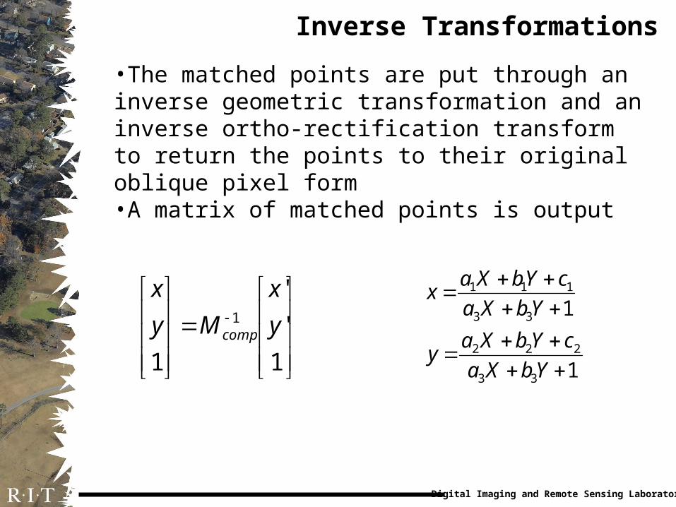
Inverse Transformations
•The matched points are put through an inverse geometric transformation and an inverse ortho-rectification transform to return the points to their original oblique pixel form•A matrix of matched points is output
1
1
33
222
33
111
YbXa
cYbXay
YbXa
cYbXax
1
'
'
1
1 y
x
My
x
comp

Digital Imaging and Remote Sensing Laboratory
Bundle Adjustment Algorithm
•Bundle adjustment algorithms allow the mapping of 2D points into 3D space using more than two images around a common point•The algorithm estimates the underlying plane geometry of a scene
Images courtesy M. Pollefeys

Digital Imaging and Remote Sensing Laboratory
3D Library Interfacing
•Using these 3D points generated from the bundle adjustment algorithm, a triangle mesh is created which forms the structure of the wire-frame scene•Also, a texture map is generated from bundle adjustment. This map is overlaid on the mesh•The full model is saved to a generic 3D format

Digital Imaging and Remote Sensing Laboratory
Methods
•Using a programming environment, engineering code will be developed to determine the feasibility of this algorithm•If it is feasible, quality metrics will be applied to determine effectiveness
•Visual analysis, absolute mean variance, and deviation from a polynomial model (RMSDE) can be used to check tie-point generation•Visual analysis and post-photogrammetric analysis can be used to check wire-frame generation

Digital Imaging and Remote Sensing Laboratory
Timetable
•September 1, 2003 – November 15, 2003•Search for previous research, background knowledge
•November 15, 2003 – April 1, 2004•Development of algorithm and engineering code
•April 1, 2004 – May 15, 2004•Complete paper, poster and presentation

Digital Imaging and Remote Sensing Laboratory
Budget
•No money will be required for this project as the investigator has all of the resources he currently requires•2 credits will be required for both Winter and Spring Quarters
•Due to the nature of the contract, most of the work performed will be done on a pay basis•Flexibility in the experimenter’s schedule was required

Digital Imaging and Remote Sensing Laboratory
References
•Honkavaara, Eija and Anton Hogholen. “Automatic Tie Point Extraction in Aerial Triangulation.” International Society for Photogrammetry and Remote Sensing, 16th Congress, Vienna, July 1996. 337-342.•Moffitt, Francis H. and Edward M. Mikhail. Photogrammetry. 3rd Ed. New York: Harper and Row, 1980.•Pollefeys, M. “3D Geometry from Images.” 15 Oct. 2003. <http://www.esat.kuleuven.ac.be/~pollefey/tutorial/tutorialECCV.html>•Walli, Karl C. “Multisensor Image Registration Utilizing the LOG Filter and FWT.” Diss. Rochester Institute of Technology, 2003.•Wolf, Paul R. Elements of Photogrammetry. 2nd Ed. New York: McGraw-Hill, 1983.

Digital Imaging and Remote Sensing Laboratory
Questions
Are there any?