digital i/o for raspberry pi starter kit data sheet - opto...
TRANSCRIPT
OPTO 22 • 800-321-6786 • 1-951-695-3000 • www.opto22.com • [email protected]
© 2016–2017 Opto 22. All rights reserved. Dimensions and specifications are subject to change. Brand or product names used herein are trademarks or registered trademarks of their respective companies or organizations.
PAGE 1
DATA SHEETForm 2210-171110
OPTO-P1-40P
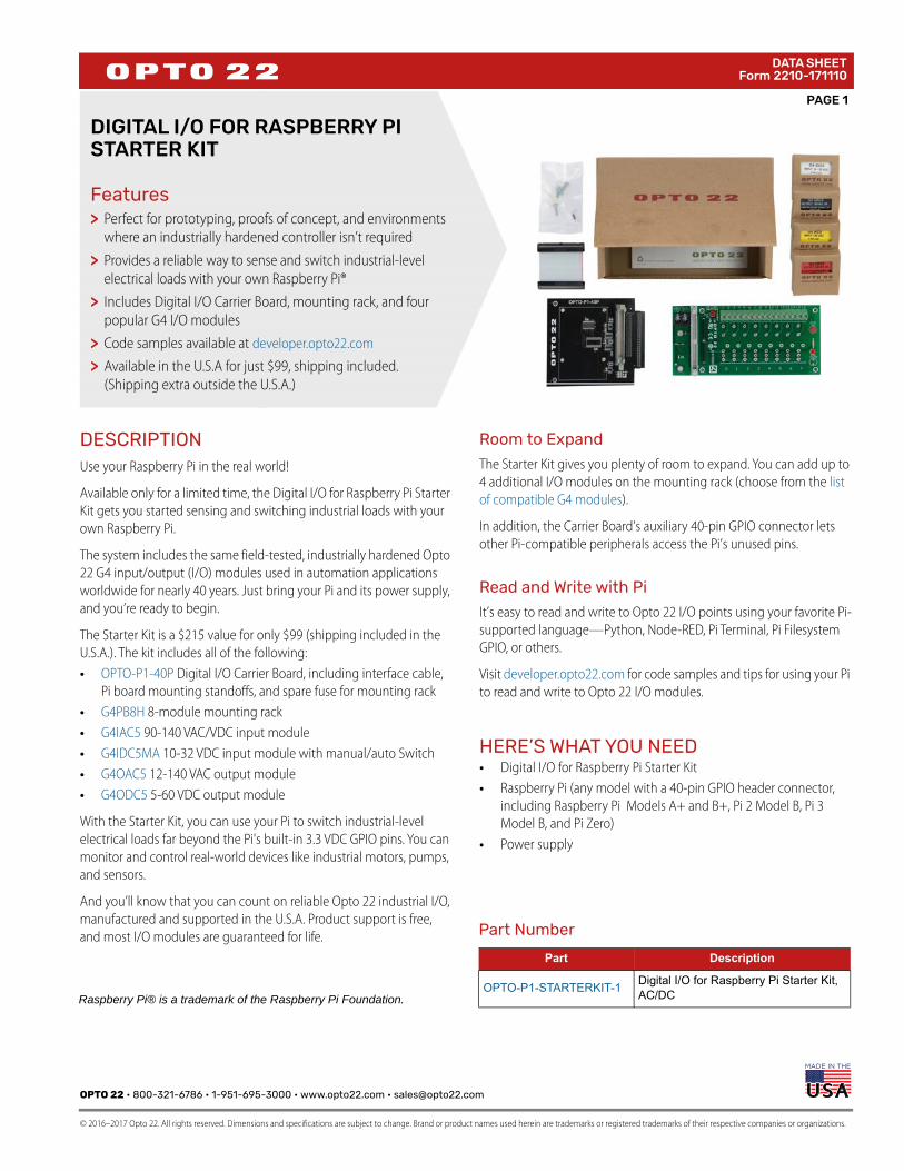
DIGITAL I/O FOR RASPBERRY PI STARTER KIT
FeaturesPerfect for prototyping, proofs of concept, and environments where an industrially hardened controller isn’t required
Provides a reliable way to sense and switch industrial-level electrical loads with your own Raspberry Pi®
Includes Digital I/O Carrier Board, mounting rack, and four popular G4 I/O modulesCode samples available at developer.opto22.com
Available in the U.S.A for just $99, shipping included. (Shipping extra outside the U.S.A.)
DESCRIPTIONUse your Raspberry Pi in the real world!
Available only for a limited time, the Digital I/O for Raspberry Pi Starter Kit gets you started sensing and switching industrial loads with your own Raspberry Pi.
The system includes the same field-tested, industrially hardened Opto 22 G4 input/output (I/O) modules used in automation applications worldwide for nearly 40 years. Just bring your Pi and its power supply, and you’re ready to begin.
The Starter Kit is a $215 value for only $99 (shipping included in the U.S.A.). The kit includes all of the following:• OPTO-P1-40P Digital I/O Carrier Board, including interface cable,
Pi board mounting standoffs, and spare fuse for mounting rack • G4PB8H 8-module mounting rack • G4IAC5 90-140 VAC/VDC input module • G4IDC5MA 10-32 VDC input module with manual/auto Switch • G4OAC5 12-140 VAC output module • G4ODC5 5-60 VDC output module
With the Starter Kit, you can use your Pi to switch industrial-level electrical loads far beyond the Pi's built-in 3.3 VDC GPIO pins. You can monitor and control real-world devices like industrial motors, pumps, and sensors.
And you’ll know that you can count on reliable Opto 22 industrial I/O, manufactured and supported in the U.S.A. Product support is free, and most I/O modules are guaranteed for life.
Room to Expand
The Starter Kit gives you plenty of room to expand. You can add up to 4 additional I/O modules on the mounting rack (choose from the list of compatible G4 modules).
In addition, the Carrier Board’s auxiliary 40-pin GPIO connector lets other Pi-compatible peripherals access the Pi’s unused pins.
Read and Write with Pi
It’s easy to read and write to Opto 22 I/O points using your favorite Pi-supported language—Python, Node-RED, Pi Terminal, Pi Filesystem GPIO, or others.
Visit developer.opto22.com for code samples and tips for using your Pi to read and write to Opto 22 I/O modules.
HERE’S WHAT YOU NEED• Digital I/O for Raspberry Pi Starter Kit• Raspberry Pi (any model with a 40-pin GPIO header connector,
including Raspberry Pi Models A+ and B+, Pi 2 Model B, Pi 3 Model B, and Pi Zero)
• Power supply
>
>
>
>>
Part Number
Part Description
OPTO-P1-STARTERKIT-1Digital I/O for Raspberry Pi Starter Kit, AC/DCRaspberry Pi® is a trademark of the Raspberry Pi Foundation.

PAGE 2
OPTO 22 • 800-321-6786 • 1-951-695-3000 • www.opto22.com • [email protected]
© 2016–2017 Opto 22. All rights reserved. Dimensions and specifications are subject to change. Brand or product names used herein are trademarks or registered trademarks of their respective companies or organizations.
DATA SHEETForm 2210-171110
GETTING STARTEDThe Starter Kit works with any model Pi with a 40-pin header connector. Here’s what’s in the box:
1. Snap the Carrier Board onto the G4 mounting rack connector.2. Carefully open the bag of small parts.
3. Use the four screws to secure the Pi to the top of the Carrier Board, placing a standoff between the Pi and the Board for each screw.
4. Insert one end of the interface cable into your Pi's GPIO connector. Insert the other end into the Carrier Board’s gray connector, making sure it locks in place.
5. Remove an I/O module from its box and carefully install it in position 0 on the board. Secure it with its integral screw.
6. Install and secure the other 3 modules next to the first one.
7. Follow “Field Wiring Diagrams” on page 4 to wire real-world sensors and devices to the mounting rack.
CAUTION: AC wiring is dangerous and should be done by a qualified electrician.
For additional wiring information and complete specifications, see form 2208, the Digital I/O for Raspberry Pi Selection Guide. (This guide also shows all the other Opto 22 I/O modules you can use with your Pi.)
Small parts G4 I/O modules
Interface cable Carrier Board G4 mounting rack
Fuse Standoffs
Screws
Terminal strip for wiring

OPTO 22 • 800-321-6786 • 1-951-695-3000 • www.opto22.com • [email protected]
© 2016–2017 Opto 22. All rights reserved. Dimensions and specifications are subject to change. Brand or product names used herein are trademarks or registered trademarks of their respective companies or organizations.
PAGE 3
DATA SHEETForm 2210-171110
8. Plug in your Pi’s power supply. (If you’re using peripherals, see “Powering Peripherals” on page 3.)
9. Use your favorite Pi-supported programming language to read and write to the I/O points.
Visit developer.opto22.com for code samples and tips for using your Pi to read and write to Opto 22 I/O modules.
The mapping diagram at right and the “Mapping Overlay for Raspberry Pi” on page 3will help you know which pins apply to each module on the rack.
NOTE: Opto 22 I/O modules use negative true logic; that is, a zero bit means On and a 1 bit means Off. When reading and writing to I/O points, remember that 0 is On and 1 is Off.
Powering Peripherals
IMPORTANT: If your Pi uses USB-powered peripherals (especially hard drives or WiFi dongles), do the following: • Connect a 5 V power supply rated 2.5 A to 5 A to the G4 rack’s
power terminals (located underneath the Carrier Board).• Replace the G4 rack’s standard 1 A fuse with the 5 A fuse that
came in the bag of small parts. (If you need to replace this fuse, it is part number FUSE05B—10 pack.)
MORE INFORMATIONSee the Digital I/O for Raspberry Pi Selection Guide for specifications and information about other I/O modules you can use with your Pi.
Mapping: GPIO Pins to G4 Modules
MAPPING OVERLAY FOR RASPBERRY PI
Place this overlay over your Pi’s GPIO pins for a handy mapping reference. You can download the template from developer.opto22.com.

PAGE 4
OPTO 22 • 800-321-6786 • 1-951-695-3000 • www.opto22.com • [email protected]
© 2016–2017 Opto 22. All rights reserved. Dimensions and specifications are subject to change. Brand or product names used herein are trademarks or registered trademarks of their respective companies or organizations.
DATA SHEETForm 2210-171110
FIELD WIRING DIAGRAMSCAUTION: AC power is dangerous! All AC wiring should be done by a qualified electrician.
For specifications and additional wiring information, see the Digital I/O for Raspberry Pi Selection Guide.
G4IAC5—Digital AC input, 90-140 VAC
G4IDC5MA—Digital DC input, 10-32 VDC, with manual/auto switch
PAGE 5
OPTO 22 • www.opto22.com SALES • [email protected] SUPPORT • [email protected] Business Park Dr. Temecula, CA 92590-3614 800-321-6786 • 1-951-695-3000 800-835-6786 • 1-951-695-3080
© 2016–2017 Opto 22. All rights reserved. Dimensions and specifications are subject to change. Brand or product names used herein are trademarks or registered trademarks of their respective companies or organizations.
DATA SHEETForm 2210-171110
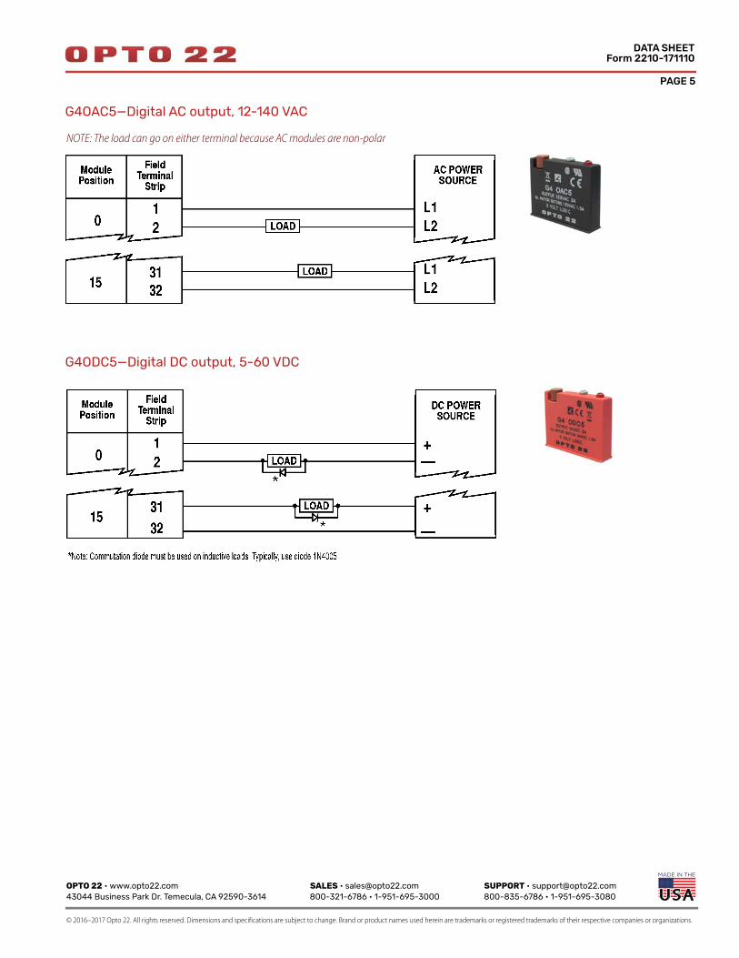
G4OAC5—Digital AC output, 12-140 VAC
G4ODC5—Digital DC output, 5-60 VDC
NOTE: The load can go on either terminal because AC modules are non-polar

OPTO 22 • www.opto22.com SALES • [email protected] SUPPORT • [email protected] Business Park Dr. Temecula, CA 92590-3614 800-321-6786 • 1-951-695-3000 800-835-6786 • 1-951-695-3080
© 2012–2017 Opto 22. All rights reserved. Dimensions and specifications are subject to change. Brand or product names used herein are trademarks or registered trademarks of their respective companies or organizations.
More about Opto 22
Form 1335-170413
PRODUCTSOpto 22 develops and manufactures reliable, easy-to-use, open standards-based hardware and software products used worldwide.
Industrial automation, process control, building automation, industrial refrigeration, remote monitoring, data acquisition, and Industrial Internet of Things (IIoT) applications all rely on Opto 22.
groov
Monitor and control your equipment from anywhere using your smartphone or tablet with groov. Build your own mobile app easily—just drag, drop, and tag. No programming or coding. Visit groov.com for more information and your free trial.
SNAP PAC System
Developer- and IIoT-ready, the SNAP PAC System connects physical assets to databases and applications using open standards. The SNAP PAC System consists of four integrated components: • SNAP PAC controllers• PAC Project™ Software Suite• SNAP PAC brains• SNAP I/O™
SNAP PAC Controllers
SNAP PAC programmable automation controllers handle a wide range of digital, analog, and serial functions for data collection, remote monitoring, process control, and discrete and hybrid manufacturing.
For IIoT applications and easier integration with company systems, standalone and rack-mounted SNAP PACs include a built-in HTTP/HTTPS server and RESTful API (application program interface). The REST API gives you secure, direct access to I/O and variable data using your choice of programming languages. No middleware, protocol converters, drivers, or gateways needed.
Based on open Ethernet and Internet Protocol (IP) standards, SNAP PACs make it easier to build or extend a system without the expense and limitations of proprietary networks and protocols.
PAC Project Software Suite
Opto 22’s PAC Project Software Suite offers full-featured, cost-effective control programming, HMI (human machine interface), OPC server, and database connectivity software.
Control programming includes both easy-to-learn flowcharts and optional scripting. Commands are in plain English; variables and I/O point names are fully descriptive.
PAC Project Basic offers control and HMI tools and is free for download on our website, www.opto22.com. PAC Project Professional, available for separate purchase, adds one SoftPAC software-based controller, OptoOPCServer, OptoDataLink, options for controller redundancy or segmented networking, and support for legacy Opto 22 serial mistic™ I/O units.
SNAP PAC Brains
While SNAP PAC controllers provide central control and data distribution, SNAP PAC brains provide distributed intelligence for I/O processing and communications. Brains offer analog, digital, and serial functions, including thermocouple linearization, local PID loop control, watchdog, totalizing, and much more.
SNAP I/O
I/O provides the local connection to sensors and equipment. Opto 22 SNAP I/O offers 1 to 32 points of reliable I/O per module. Analog, digital, and serial modules are mixed on one mounting rack and controlled by a SNAP PAC brain or rack-mounted PAC.
QUALITYFounded in 1974, Opto 22 has established a worldwide reputation for high-quality products. All are made in the U.S.A. at our manufacturing facility in Temecula, California.
Because we test each product twice before it leaves our factory, rather than only testing a sample of each batch, we can guarantee most solid-state relays and optically isolated I/O modules for life.
FREE PRODUCT SUPPORTOpto 22’s California-based Product Support
Group offers free, comprehensive technical support for Opto 22 products from engineers with decades of training and experience. Support is available in English and Spanish by phone or email, Monday–Friday, 7 a.m. to 5 p.m. PST.
Support is always available on our website: how-to videos, user’s guides, OptoKnowledgeBase, self-training guide, troubleshooting, and OptoForums. In addition, hands-on training is available for free at our Temecula, California headquarters, and you can register online.
PURCHASING OPTO 22 PRODUCTSOpto 22 products are sold directly and through a worldwide network of distributors, partners, and system integrators. For more information, contact Opto 22 headquarters at 800-321-6786 (toll-free in the U.S. and Canada) or 951-695-3000, or visit our website at www.opto22.com.