digital logic circuits - people.hsc.edupeople.hsc.edu/faculty-staff/robbk/math262/lectures/spring...
TRANSCRIPT

Digital Logic CircuitsLecture 5
Section 2.4
Robb T. Koether
Hampden-Sydney College
Wed, Jan 23, 2013
Robb T. Koether (Hampden-Sydney College) Digital Logic Circuits Wed, Jan 23, 2013 1 / 25

1 Logic Gates
2 Normal Forms
3 Designing Circuits
4 Assignment
Robb T. Koether (Hampden-Sydney College) Digital Logic Circuits Wed, Jan 23, 2013 2 / 25

Outline
1 Logic Gates
2 Normal Forms
3 Designing Circuits
4 Assignment
Robb T. Koether (Hampden-Sydney College) Digital Logic Circuits Wed, Jan 23, 2013 3 / 25

Logic Gates
There are three basic gates.AND-gateOR-gateNOT-gate
Two other gates.NAND-gateNOR-gate
Robb T. Koether (Hampden-Sydney College) Digital Logic Circuits Wed, Jan 23, 2013 4 / 25

AND-Gate
p q Output1 1 11 0 00 1 00 0 0
An AND-gate.The output is 1 if both inputs are 1.The output is 0 if either input is 0.
Robb T. Koether (Hampden-Sydney College) Digital Logic Circuits Wed, Jan 23, 2013 5 / 25

OR-Gate
p q Output1 1 11 0 10 1 10 0 0
An OR-gate.The output is 1 if either input is 1.The output is 0 if both inputs are 0.
Robb T. Koether (Hampden-Sydney College) Digital Logic Circuits Wed, Jan 23, 2013 6 / 25
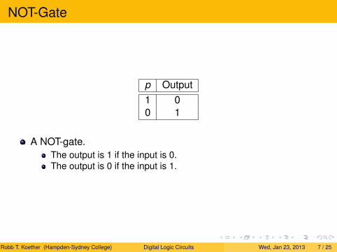
NOT-Gate
p Output1 00 1
A NOT-gate.The output is 1 if the input is 0.The output is 0 if the input is 1.
Robb T. Koether (Hampden-Sydney College) Digital Logic Circuits Wed, Jan 23, 2013 7 / 25

NAND-Gate
p q Output1 1 01 0 10 1 10 0 1
An NAND-gate.The output is 0 if both inputs are 1.The output is 1 if either input is 0.
Robb T. Koether (Hampden-Sydney College) Digital Logic Circuits Wed, Jan 23, 2013 8 / 25

NOR-Gate
p q Output1 1 01 0 00 1 00 0 1
An NOR-gate.The output is 0 if either input is 1.The output is 1 if both inputs are 0.
Robb T. Koether (Hampden-Sydney College) Digital Logic Circuits Wed, Jan 23, 2013 9 / 25

Outline
1 Logic Gates
2 Normal Forms
3 Designing Circuits
4 Assignment
Robb T. Koether (Hampden-Sydney College) Digital Logic Circuits Wed, Jan 23, 2013 10 / 25

Disjunctive Normal Form
A logical expression is in disjunctive normal form (DNF) ifIt is a disjunction of clauses,Each clause if a conjunction of variables and negations of variables.Each variable or its negation appears in each clause exactly once.
Robb T. Koether (Hampden-Sydney College) Digital Logic Circuits Wed, Jan 23, 2013 11 / 25

Example
p → q ≡ (p ∧ q) ∨ (∼ p ∧ q) ∨ (∼ p∧ ∼ q).
p ↔ q ≡ (p ∧ q) ∨ (∼ p∧ ∼ q).
p | q ≡ (p∧ ∼ q) ∨ (∼ p ∧ q) ∨ (∼ p∧ ∼ q).
p ↓ q ≡∼ p∧ ∼ q.
What are disjunctive normal forms for T and F?
Robb T. Koether (Hampden-Sydney College) Digital Logic Circuits Wed, Jan 23, 2013 12 / 25

Conjunctive Normal Form
A logical expression is in conjunctive normal form (CNF) ifIt is a conjunction of clauses,Each clause if a disjunction of variables and negations of variables.Each variable or its negation appears in each clause exactly once.
Robb T. Koether (Hampden-Sydney College) Digital Logic Circuits Wed, Jan 23, 2013 13 / 25

Example
p → q ≡∼ p ∨ q.
p ↔ q ≡ (p∨ ∼ q) ∧ (∼ p ∨ q).
p | q ≡∼ p∨ ∼ q.
p ↓ q ≡ (p∨ ∼ q) ∨ (∼ p ∨ q) ∨ (∼ p∨ ∼ q).
What are conjunctive normal forms for T and F?
Robb T. Koether (Hampden-Sydney College) Digital Logic Circuits Wed, Jan 23, 2013 14 / 25

Outline
1 Logic Gates
2 Normal Forms
3 Designing Circuits
4 Assignment
Robb T. Koether (Hampden-Sydney College) Digital Logic Circuits Wed, Jan 23, 2013 15 / 25

Output Tables
Input Output1 1 01 0 10 1 00 0 0
An output table shows the output of a logical function for everypossible combination of inputs.
Robb T. Koether (Hampden-Sydney College) Digital Logic Circuits Wed, Jan 23, 2013 16 / 25

Designing Circuits
To design a circuit that represents a logical function,Write an output table for the circuit. The table reveals the DNF formof the function.Write the logical expression and simplify it, if possible.Draw the circuit using AND-gates, OR-gates, and NOT-gates (andNAND-gates and NOR-gates).
Robb T. Koether (Hampden-Sydney College) Digital Logic Circuits Wed, Jan 23, 2013 17 / 25

Example
Input Output1 1 01 0 10 1 00 0 0
Design a circuit for the above function (which is ∼ (p → q)).
Robb T. Koether (Hampden-Sydney College) Digital Logic Circuits Wed, Jan 23, 2013 18 / 25

Example
Design a circuit for (p → q) ∧ (q ↔∼ r).
Robb T. Koether (Hampden-Sydney College) Digital Logic Circuits Wed, Jan 23, 2013 19 / 25

Example
Inputp q r Output1 1 1 01 1 0 11 0 1 01 0 0 00 1 1 00 1 0 10 0 1 10 0 0 0
Produce the output table for (p → q) ∧ (q ↔∼ r).
Robb T. Koether (Hampden-Sydney College) Digital Logic Circuits Wed, Jan 23, 2013 20 / 25

Example
Based on the output table, the DNF of
(p → q) ∧ (q ↔∼ r)
is(p ∧ q∧ ∼ r) ∨ (∼ p ∧ q∧ ∼ r) ∨ (∼ p∧ ∼ q ∧ r).
I do not see any way to simplify this.Draw the circuit.
Robb T. Koether (Hampden-Sydney College) Digital Logic Circuits Wed, Jan 23, 2013 21 / 25

Example
Design a logic circuit for
(p ∧ q) ∨ (∼ q∧ ∼ r) ∨ r .
Use the conjunctive normal form of
(p ∧ q) ∨ (∼ q∧ ∼ r) ∨ r
to design a circuit.
Robb T. Koether (Hampden-Sydney College) Digital Logic Circuits Wed, Jan 23, 2013 22 / 25

Outline
1 Logic Gates
2 Normal Forms
3 Designing Circuits
4 Assignment
Robb T. Koether (Hampden-Sydney College) Digital Logic Circuits Wed, Jan 23, 2013 23 / 25

Assignment
AssignmentRead Section 2.4, pages 64 - 75.Exercises 1, 2, 5, 6, 9, 10, 15, 17, 18, 19, 24, 25, 32, page 65.
Robb T. Koether (Hampden-Sydney College) Digital Logic Circuits Wed, Jan 23, 2013 24 / 25

Collected Homework 1
Collected Homework 1Page 37, Exercises 15, 42.Page 49, Exercises 6, 17.Page 61, Exercises 11, 23.Due at the beginning of class on Thu, Jan 24, 2013.
Robb T. Koether (Hampden-Sydney College) Digital Logic Circuits Wed, Jan 23, 2013 25 / 25