digital logic design lecture 18. announcements hw 6 up on webpage, due on thursday, 11/6
TRANSCRIPT
Digital Logic Design
Lecture 18

Announcements
• HW 6 up on webpage, due on Thursday, 11/6
Agenda
• MSI Components– Binary Adders and Subtracters (5.1, 5.1.1)– Carry Lookahead Adders (5.1.2, 5.1.3)– Decimal Adders (5.2)– Comparators (5.3)
Scale of Integration
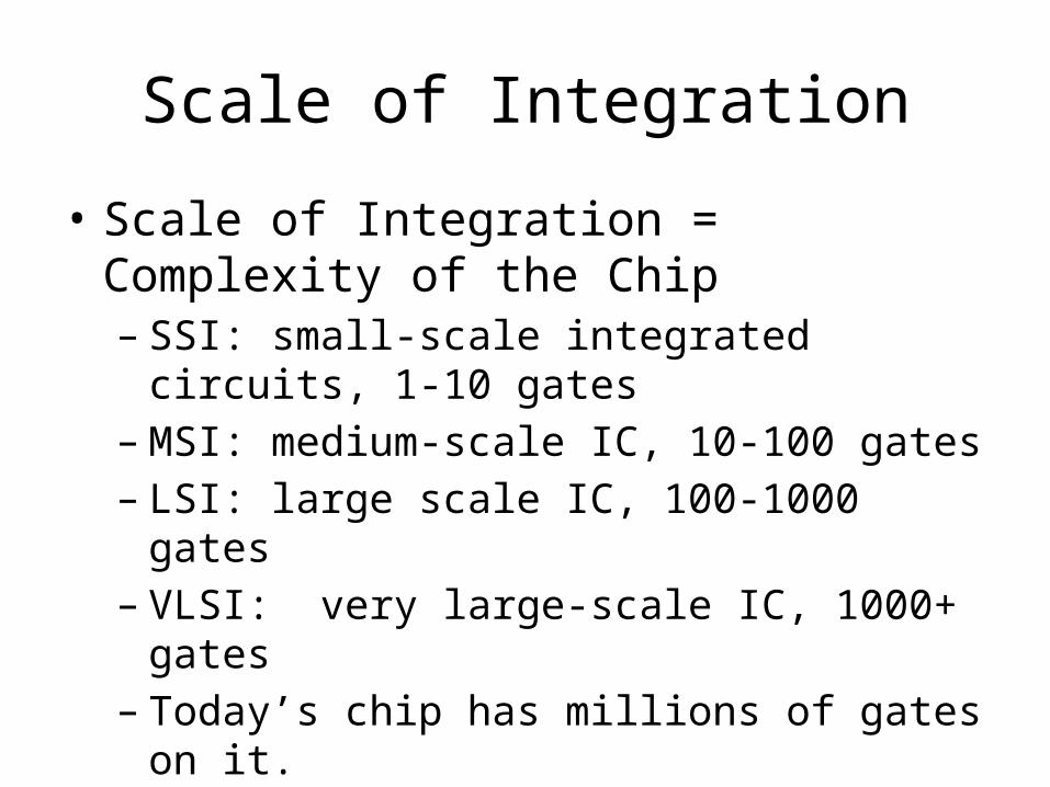
• Scale of Integration = Complexity of the Chip– SSI: small-scale integrated circuits, 1-10 gates– MSI: medium-scale IC, 10-100 gates– LSI: large scale IC, 100-1000 gates– VLSI: very large-scale IC, 1000+ gates– Today’s chip has millions of gates on it.
• MSI components: adder, subtracter, comparator, decoder, encoder, multiplexer.
Scale of Integration
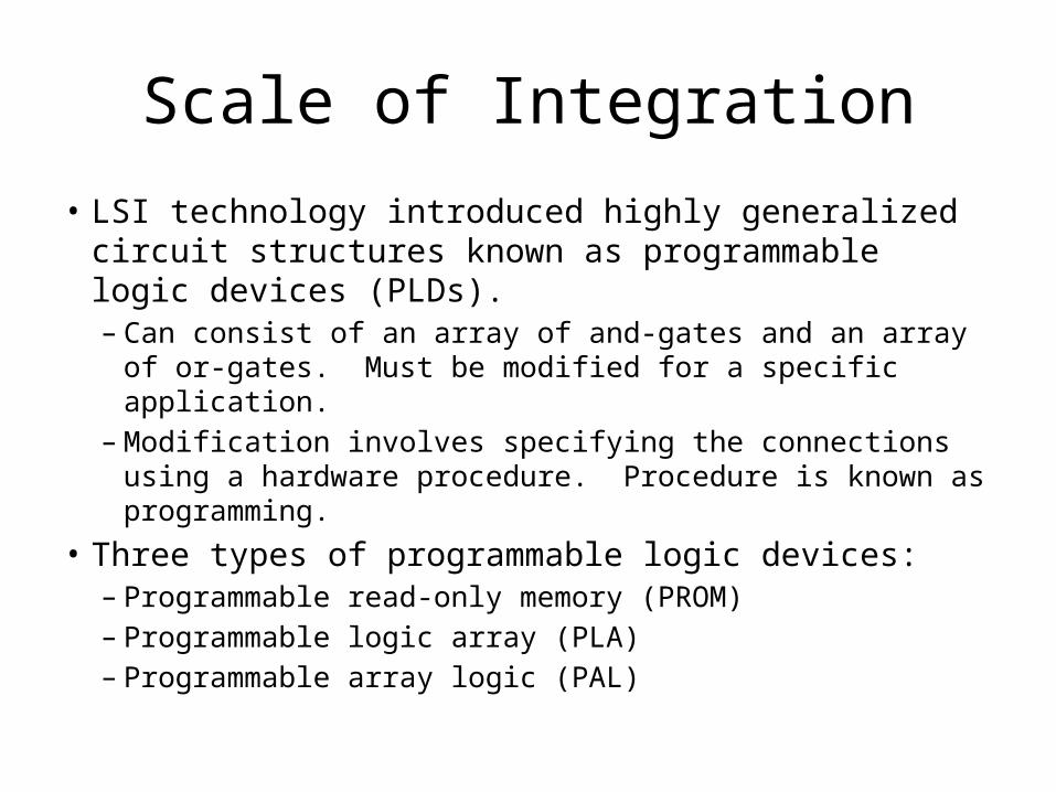
• LSI technology introduced highly generalized circuit structures known as programmable logic devices (PLDs). – Can consist of an array of and-gates and an array of or-
gates. Must be modified for a specific application. – Modification involves specifying the connections using a
hardware procedure. Procedure is known as programming.• Three types of programmable logic devices:
– Programmable read-only memory (PROM)– Programmable logic array (PLA)– Programmable array logic (PAL)
MSI Components
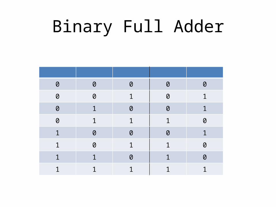
Binary Full Adder
0 0 0 0 0
0 0 1 0 1
0 1 0 0 1
0 1 1 1 0
1 0 0 0 1
1 0 1 1 0
1 1 0 1 0
1 1 1 1 1
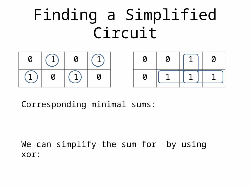
Finding a Simplified Circuit
0 1 0 1
1 0 1 0
0 0 1 0
0 1 1 1
Corresponding minimal sums:
We can simplify the sum for by using xor:
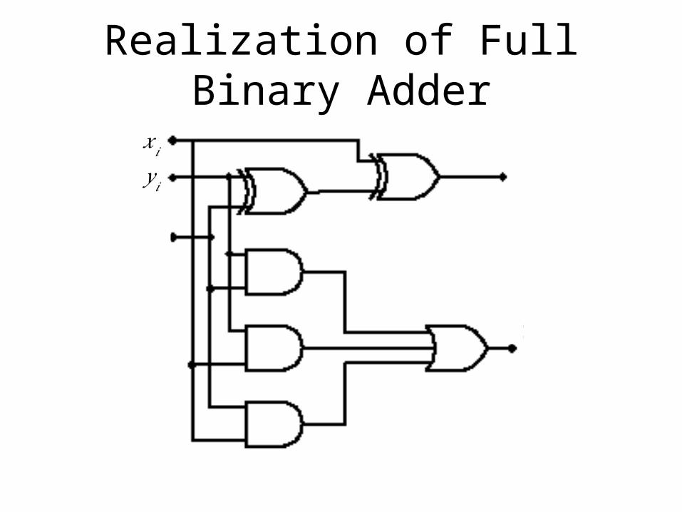
Realization of Full Binary Adder
𝑥𝑖𝑦 𝑖
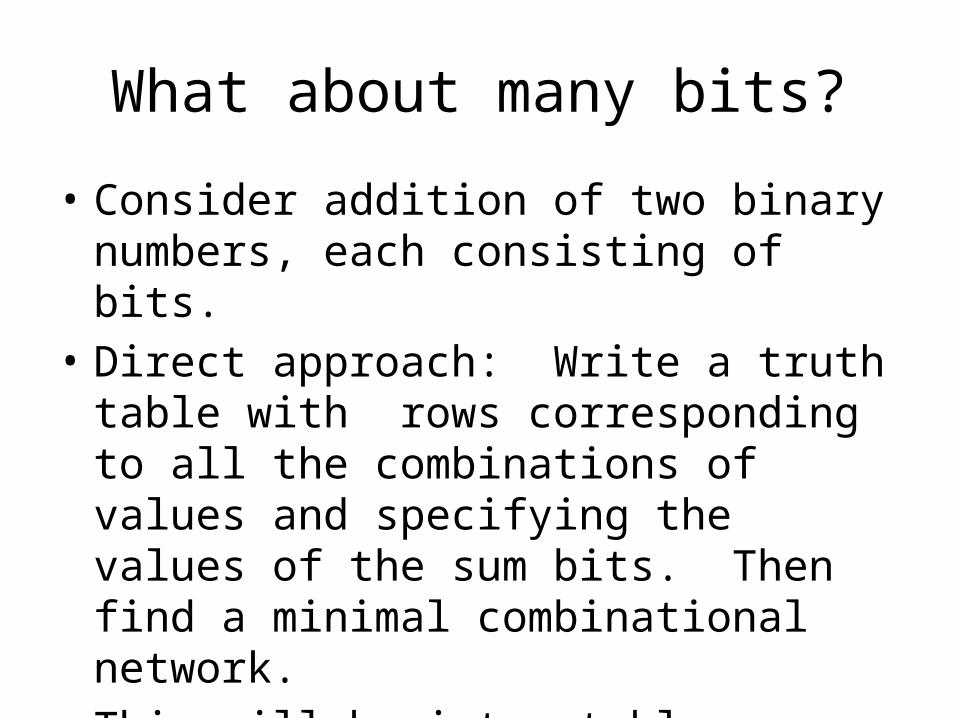
What about many bits?
• Consider addition of two binary numbers, each consisting of bits.
• Direct approach: Write a truth table with rows corresponding to all the combinations of values and specifying the values of the sum bits. Then find a minimal combinational network.
• This will be intractable.
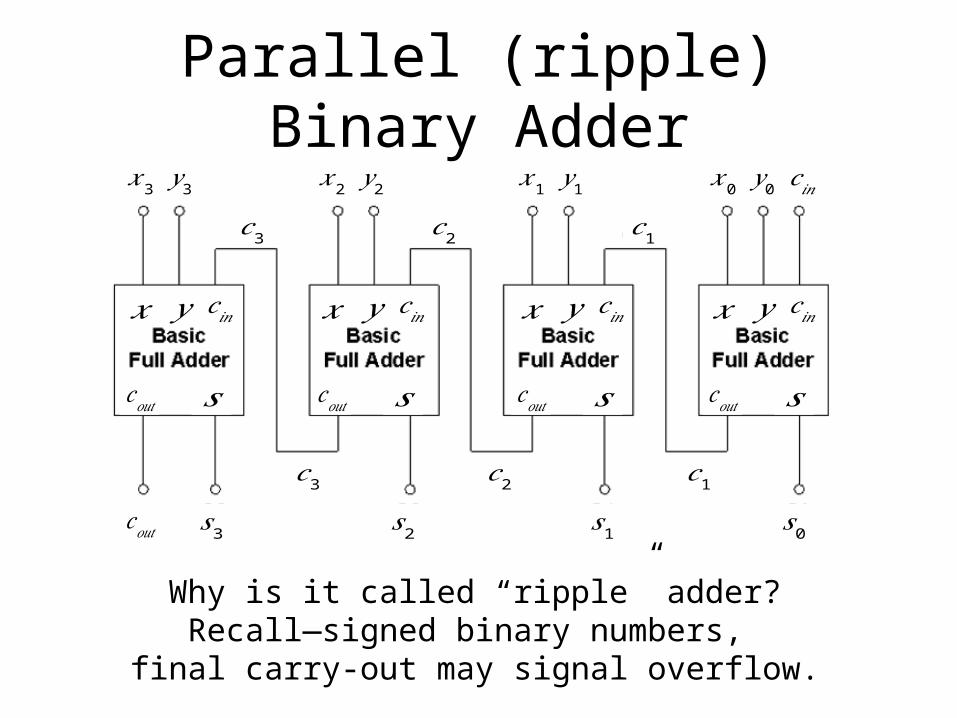
Parallel (ripple) Binary Adder
Why is it called “ripple” adder?Recall—signed binary numbers,
final carry-out may signal overflow.
𝑥3𝑦 3𝑐3
𝑐𝑜𝑢𝑡
𝑐𝑜𝑢𝑡 𝑠
𝑥𝑦𝑐 𝑖𝑛
𝑐3𝑠3
𝑥2𝑦 2𝑐2
𝑐𝑜𝑢𝑡 𝑠
𝑥𝑦𝑐 𝑖𝑛
𝑐2𝑠2
𝑥1𝑦 1𝑐1
𝑐𝑜𝑢𝑡 𝑠
𝑥𝑦𝑐 𝑖𝑛
𝑐1𝑠1
𝑥0𝑦 0
𝑐𝑜𝑢𝑡 𝑠
𝑥𝑦𝑐 𝑖𝑛
𝑠0
𝑐 𝑖𝑛
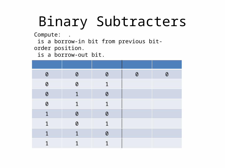
Binary Subtracters
0 0 0 0 0
0 0 1
0 1 0
0 1 1
1 0 0
1 0 1
1 1 0
1 1 1
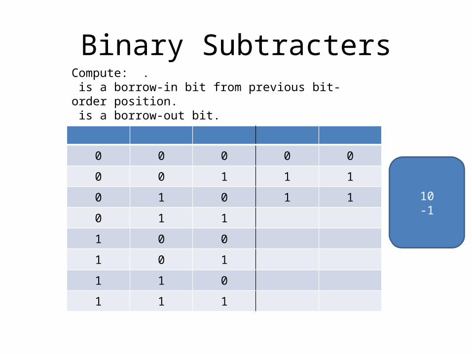
Compute: . is a borrow-in bit from previous bit-order position. is a borrow-out bit.
Binary Subtracters
0 0 0 0 0
0 0 1 1 1
0 1 0
0 1 1
1 0 0
1 0 1
1 1 0
1 1 1
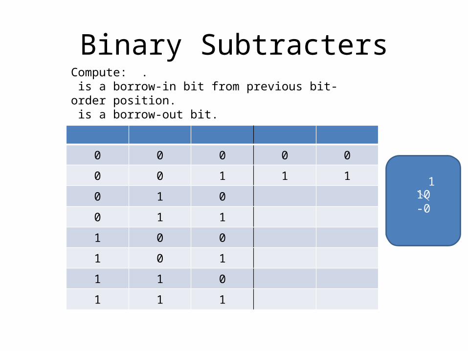
Compute: . is a borrow-in bit from previous bit-order position. is a borrow-out bit.
10-0
1
Binary Subtracters
0 0 0 0 0
0 0 1 1 1
0 1 0 1 1
0 1 1
1 0 0
1 0 1
1 1 0
1 1 1
Compute: . is a borrow-in bit from previous bit-order position. is a borrow-out bit.
10-1

Binary Subtracters
0 0 0 0 0
0 0 1 1 1
0 1 0 1 1
0 1 1 1 0
1 0 0
1 0 1
1 1 0
1 1 1
Compute: . is a borrow-in bit from previous bit-order position. is a borrow-out bit.
10-1
1
Binary Subtracters
0 0 0 0 0
0 0 1 1 1
0 1 0 1 1
0 1 1 1 0
1 0 0 0 1
1 0 1 0 0
1 1 0 0 0
1 1 1 1 1
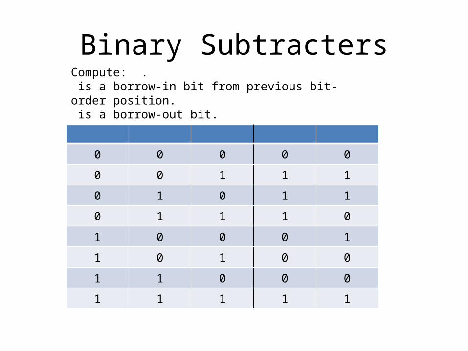
Compute: . is a borrow-in bit from previous bit-order position. is a borrow-out bit.
1
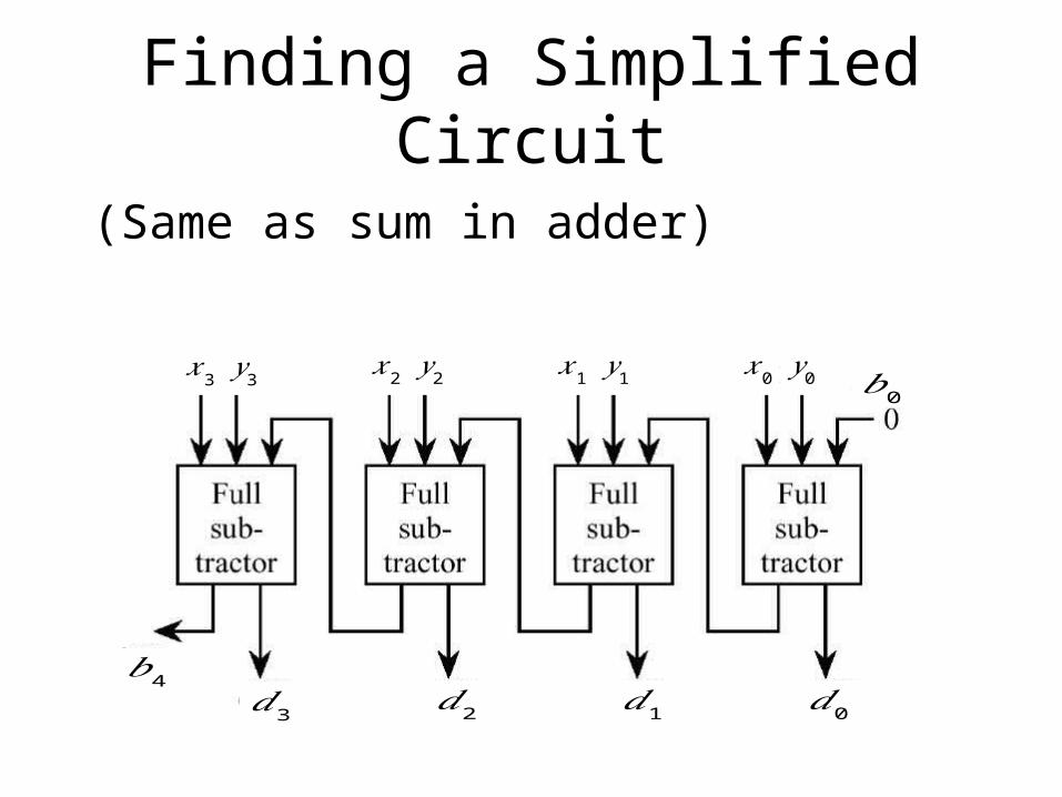
Finding a Simplified Circuit
(Same as sum in adder)
𝑥3𝑦 3
𝑑3𝑏4
𝑥2𝑦 2
𝑑2
𝑥1𝑦 1
𝑑1
𝑥0𝑦 0
𝑑0
𝑏0
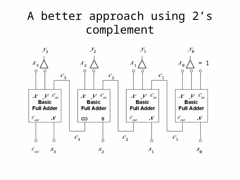
A better approach using 2’s complement
𝑥3
𝑦 3
𝑐𝑜𝑢𝑡
𝑐𝑜𝑢𝑡 𝑠
𝑥𝑦𝑐 𝑖𝑛
𝑠3
𝑐3
𝑐3
𝑥2
𝑦 2
𝑐2
𝑥𝑦𝑐 𝑖𝑛
𝑐2𝑠2
𝑥1
𝑦 1
𝑐1
𝑐𝑜𝑢𝑡 𝑠
𝑥𝑦𝑐 𝑖𝑛
𝑐1𝑠1
𝑥0
𝑦 0
𝑐𝑜𝑢𝑡 𝑠
𝑥𝑦𝑐 𝑖𝑛
𝑠0
= 1
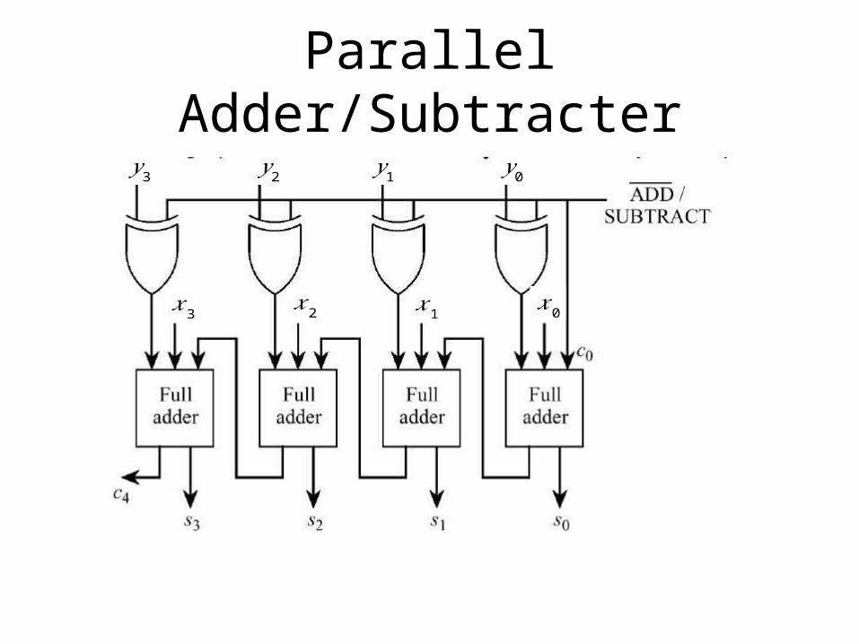
Parallel Adder/Subtracter
𝑥3
𝑦 3
𝑥2
𝑦 2
𝑥1
𝑦 1
𝑥0
𝑦 0
Carry Lookahead Adder
• Ripple effect:– If a carry is generated in the least-significant-bit the
carry must propagate through all the remaining stages.
– Assuming two-levels of logic are need to propogate the carry through each of the next higher-order stages. Delay is 2n.
• Must speed up propagation of the carries. Adders designed with this consideration in mind are called high-speed adders.
Carry Lookahead Adder
• Consider
• The first term is called the carry-generate function since it corresponds to the formation of a carry at the i-th stage.
• The second term corresponds to a previously generated carry that must propagate past the i-th stage to the next stage.
• The part of this term is called the carry-propagate function.
• Carry-generate function will be denoted by , carry-propagate function will be denoted by .
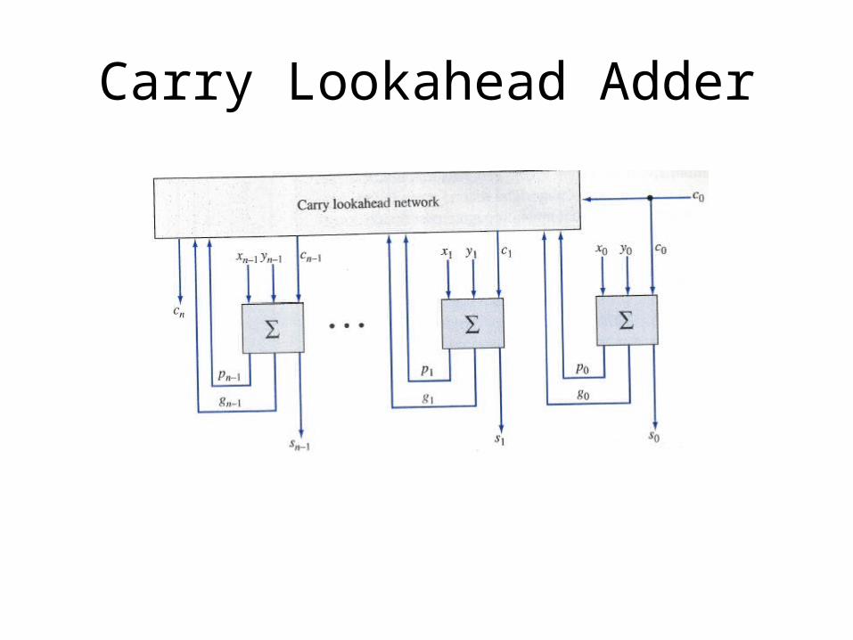
Carry Lookahead Adder
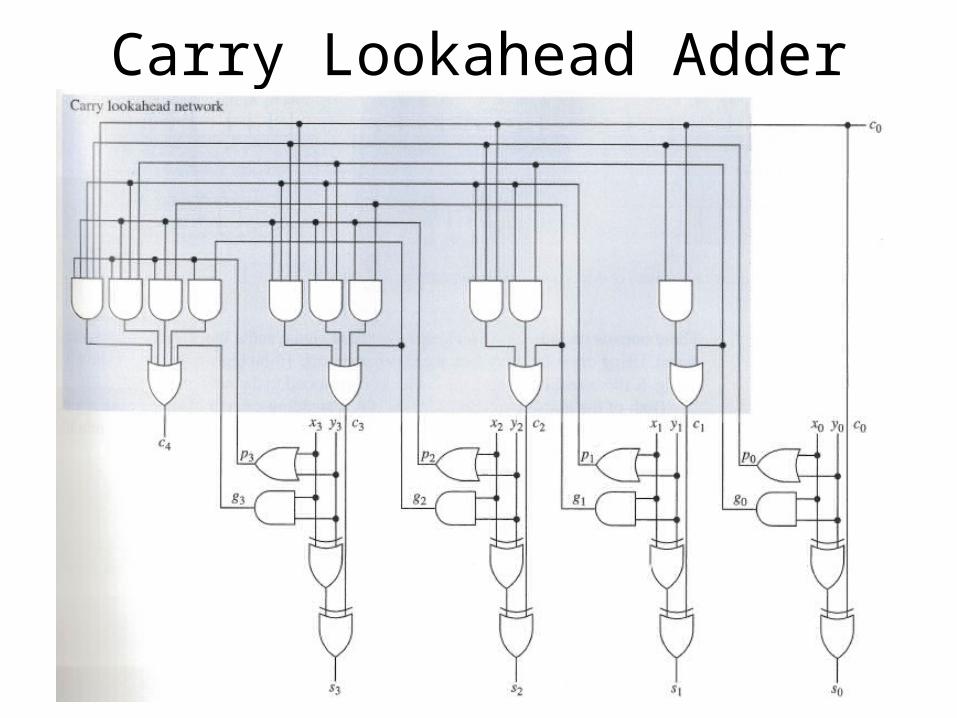
Using this general result, the output carry at each of the stages can be written in terms of the ’s, ’s and initial input carry
Carry Lookahead Adder
Why is this a good idea? Do we save on computation?
Carry Lookahead Adder
Carry Lookahead Adder
Carry Lookahead Adder
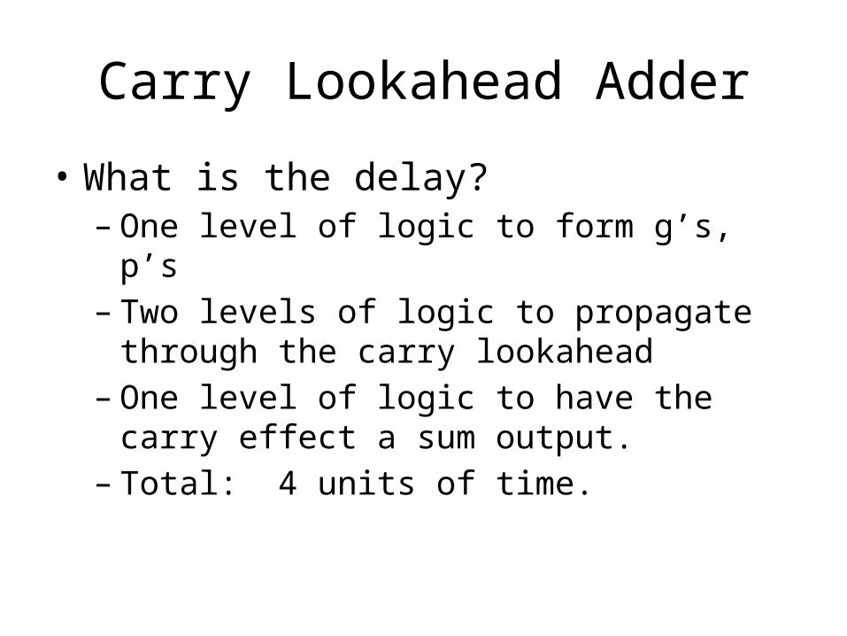
• What is the delay?– One level of logic to form g’s, p’s– Two levels of logic to propagate through the carry
lookahead– One level of logic to have the carry effect a sum
output.– Total: 4 units of time.
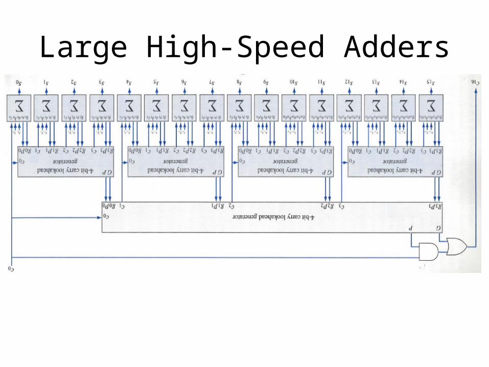
Large High-Speed Adders
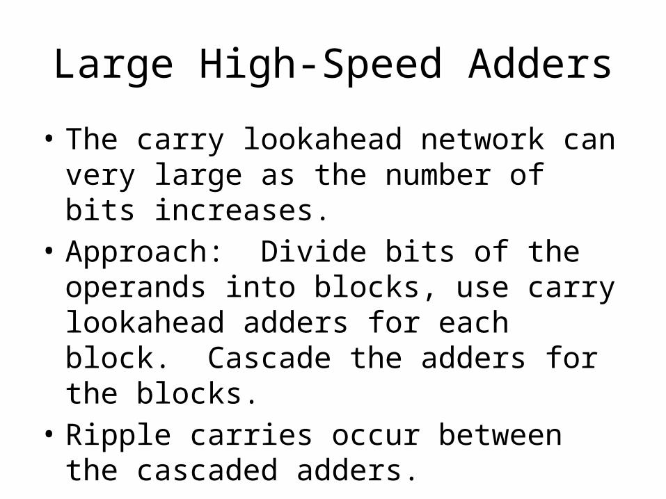
• The carry lookahead network can very large as the number of bits increases.
• Approach: Divide bits of the operands into blocks, use carry lookahead adders for each block. Cascade the adders for the blocks.
• Ripple carries occur between the cascaded adders.
Another Approach to Large High-Speed Adders
• Carry lookahead generators that generate the carry of an entire block.
• Assume 4-bit blocks.• For each block, 4-bit carry lookahead
generator outputs:
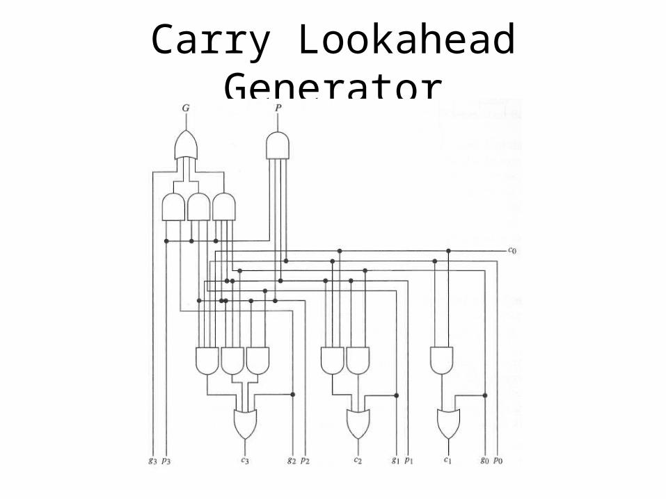
Carry Lookahead Generator
Large High-Speed Adders
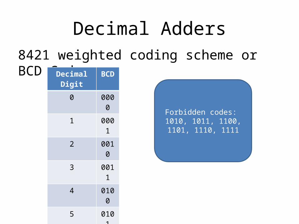
Decimal Adders8421 weighted coding scheme or BCD Code
Decimal Digit BCD
0 0000
1 0001
2 0010
3 0011
4 0100
5 0101
6 0110
7 0111
8 1000
9 1001
Forbidden codes: 1010, 1011, 1100, 1101, 1110,
1111
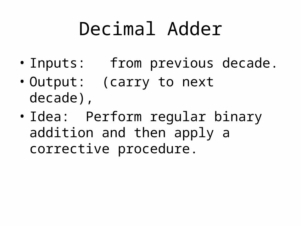
Decimal Adder
• Inputs: from previous decade.• Output: (carry to next decade), • Idea: Perform regular binary addition and
then apply a corrective procedure.