digital logic for protection & control
TRANSCRIPT

Digital Logic for Protection & Control35th Annual Hands-On Relay SchoolMarch-2018
Kevin Damron, PESr. Protection Engineer – Avista UtilitiesAdjunct Professor – Gonzaga [email protected]
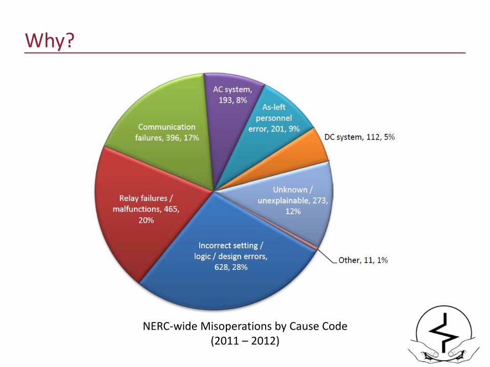
Why?
NERC-wide Misoperations by Cause Code (2011 – 2012)
AgendaFundamentals Logic Gates, Truth Tables, Logic Equations, and Schematics
Positive and Negative LogicLogic PropertiesMore Logic Latches, Edge Triggers, Timers
Examples
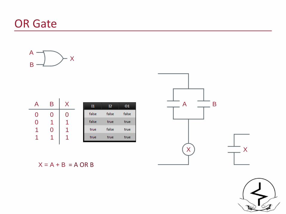
OR Gate
XA
B
A B X0 0 00 1 11 0 11 1 1
X = A + B
A B
X X
= A OR B
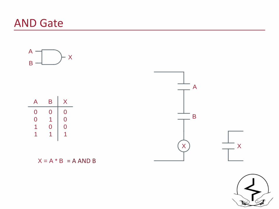
AND Gate
X = A * B
B
A
X X
XA
B
A B X0 0 00 1 01 0 01 1 1
= A AND B
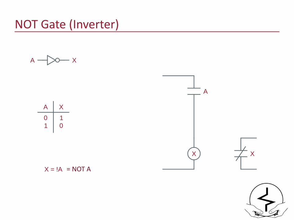
NOT Gate (Inverter)
X = !A
A
X X
XA
A X0 11 0
= NOT A

Gate Variations
OR
OR +
>1

Inverted Inputs
XA
C
A B C
0 0 00 0 10 1 00 1 1
A B
X X
B
C
X
1011
1 0 01 0 11 1 01 1 1
1111
X = A + B + !C = A OR B OR NOT C
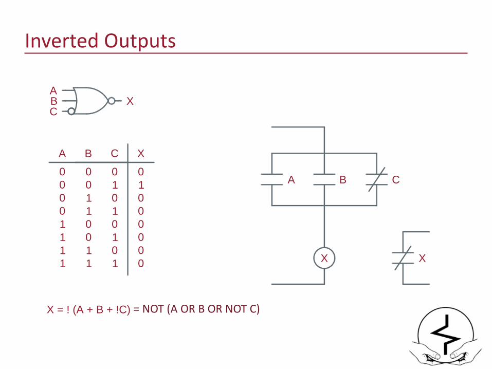
Inverted Outputs
XA
C
A B C
0 0 00 0 10 1 00 1 1
A B
X X
B
C
X0100
1 0 01 0 11 1 01 1 1
0000
X = ! (A + B + !C) = NOT (A OR B OR NOT C)
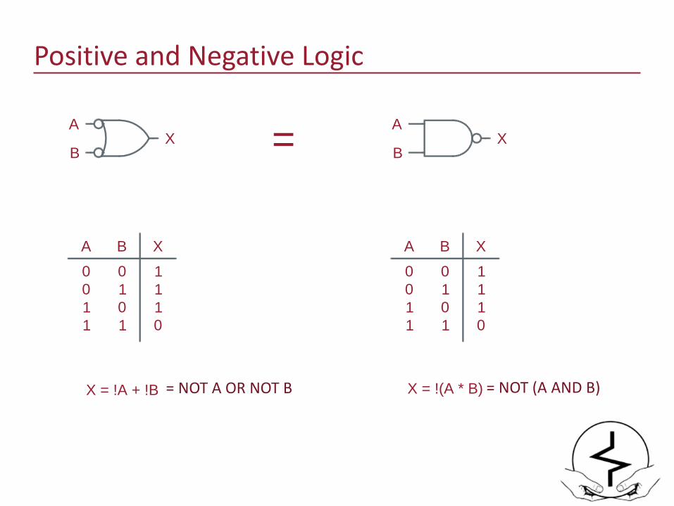
Positive and Negative Logic
XA
BX
A
B
A B X0 0 10 1 11 0 11 1 0
X = !(A * B)
A B X0 0 10 1 11 0 11 1 0
X = !A + !B
=
= NOT A OR NOT B = NOT (A AND B)
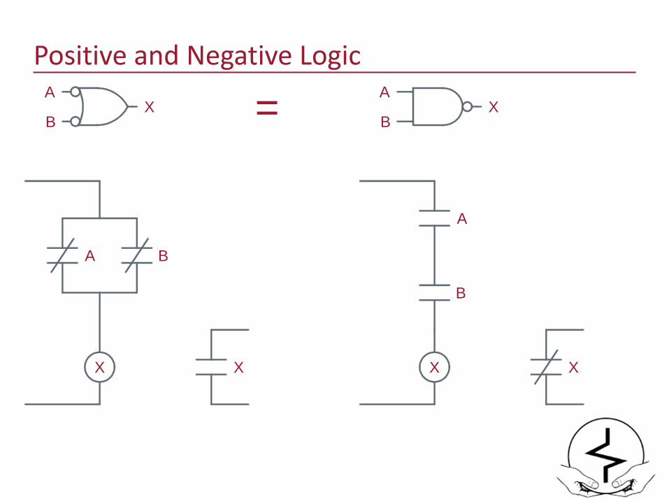
Positive and Negative Logic
=XA
B
A B
X X
XA
B
B
A
X X
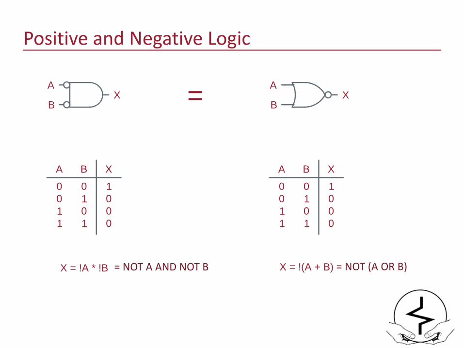
Positive and Negative Logic
A B X0 0 10 1 01 0 01 1 0
X = !A * !B
A B X0 0 10 1 01 0 01 1 0
X = !(A + B)
XA
BX
A
B =
= NOT A AND NOT B = NOT (A OR B)
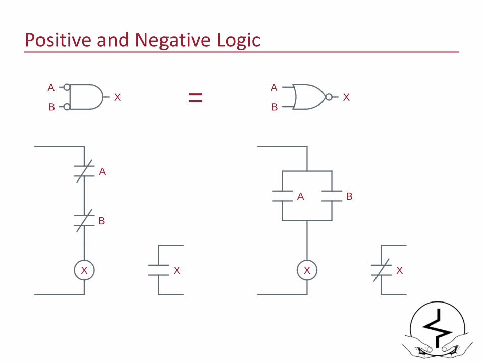
Positive and Negative Logic
XA
B
A B
X X
XA
B
B
A
X X
=
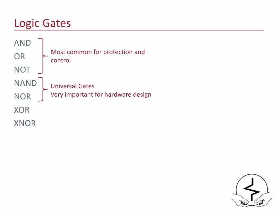
Logic GatesANDORNOTNAND NORXORXNOR
Most common for protection and control
Universal GatesVery important for hardware design
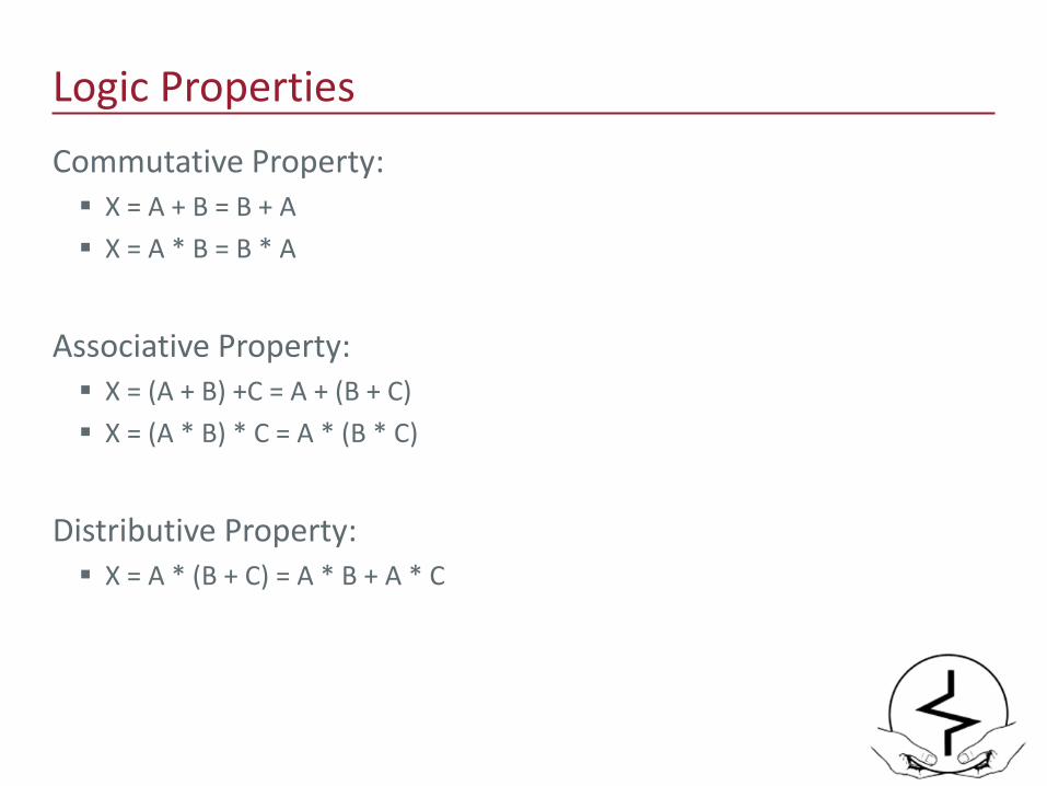
Logic PropertiesCommutative Property: X = A + B = B + A X = A * B = B * A
Associative Property: X = (A + B) +C = A + (B + C) X = (A * B) * C = A * (B * C)
Distributive Property: X = A * (B + C) = A * B + A * C

Logic PrecidenceMath: My Dear Aunt Sally = Multiply -> Divide -> Add -> Subtract
• 2 + 3 x 4 = ??• 2 + 3 x 4 = 2 + (3 x 4) = 14• 2 + 3 x 4 ≠ (2 + 3) x 4 = 20
Logic: NOT -> AND -> OR
• X = A + B * C = A or B and C• X = A + B * C = A + (B * C)• X = A + B * C ≠ (A + B) * C
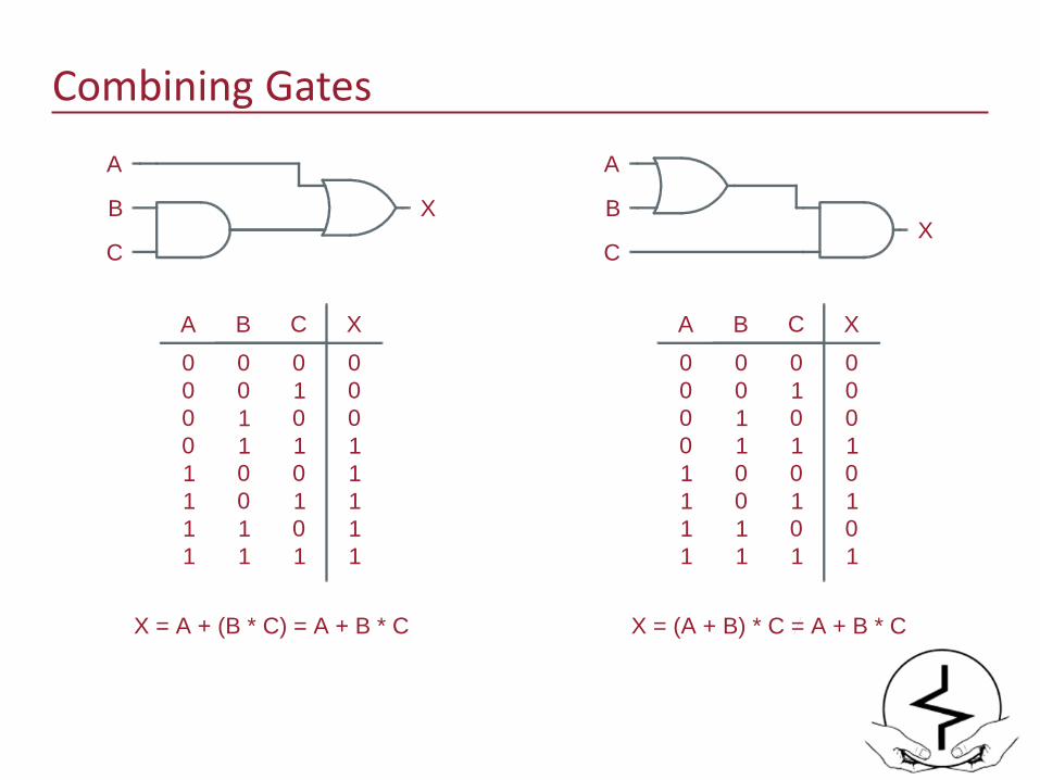
Combining GatesA
BX
C
A
B X
C
A B C
0 0 00 0 10 1 00 1 1
X0001
1 0 01 0 11 1 01 1 1
0101
X = (A + B) * C = A + B * C
A B C
0 0 00 0 10 1 00 1 1
X0001
1 0 01 0 11 1 01 1 1
1111
X = A + (B * C) = A + B * C
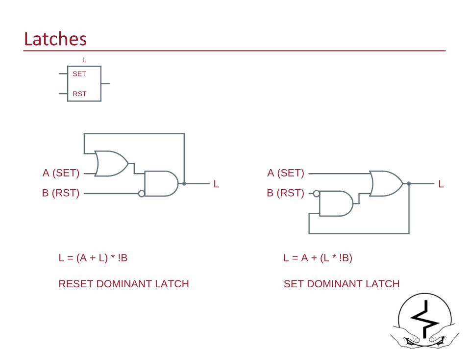
Latches
A (SET)L
B (RST)
L = A + (L * !B)
RESET DOMINANT LATCH SET DOMINANT LATCH
L
SET
RST
A (SET)L
B (RST)
L = (A + L) * !B
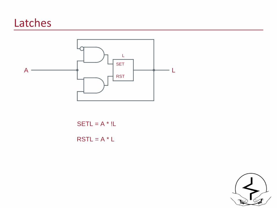
Latches
L
SET
RSTA L
SETL = A * !L
RSTL = A * L
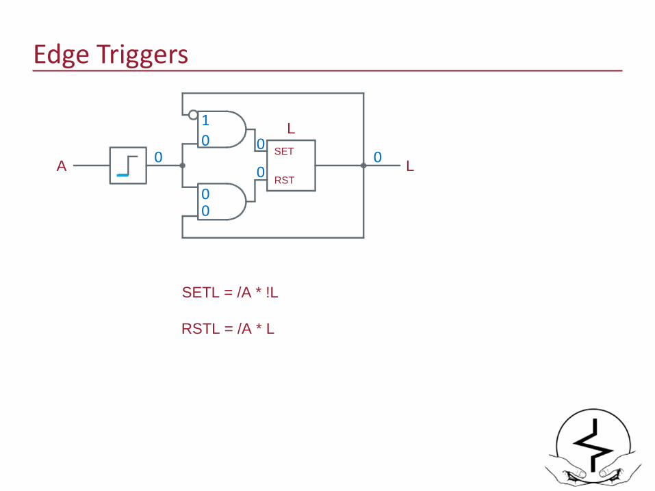
Edge Triggers
LSET
RSTA L
SETL = /A * !L
RSTL = /A * L
00
10 0
00
0

Edge Triggers
LSET
RSTA L
SETL = /A * !L
RSTL = /A * L
1
11 1
11
01

Edge Triggers
LSET
RSTA L
SETL = /A * !L
RSTL = /A * L
0
10 0
00
00
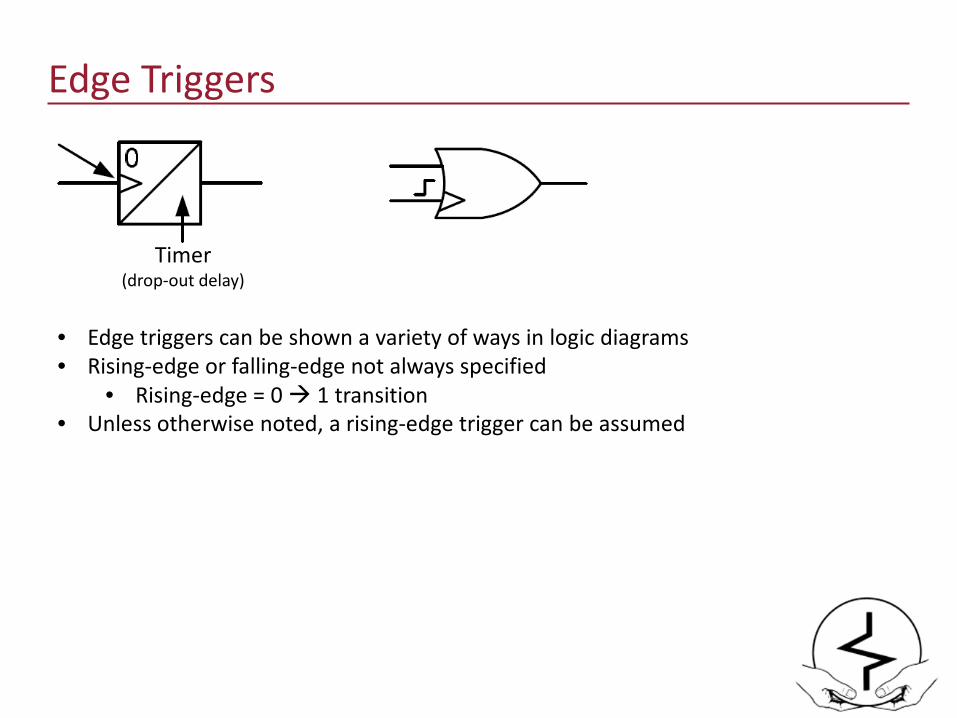
Edge Triggers
Timer(drop-out delay)
• Edge triggers can be shown a variety of ways in logic diagrams• Rising-edge or falling-edge not always specified
• Rising-edge = 0 1 transition• Unless otherwise noted, a rising-edge trigger can be assumed
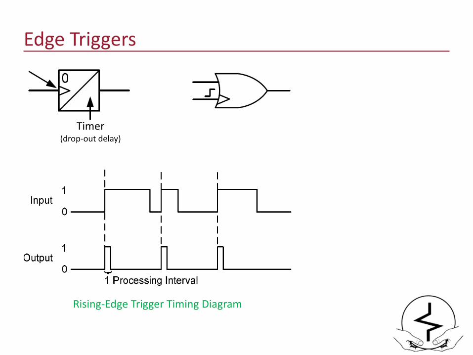
Edge Triggers
Timer(drop-out delay)
Rising-Edge Trigger Timing Diagram
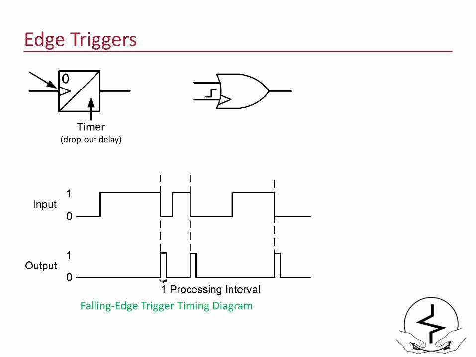
Edge Triggers
Timer(drop-out delay)
Falling-Edge Trigger Timing Diagram

Timers
2
0
X
A XT
X = AXPU = 2XDO = 0
A
XT
10 2 3 4 5 6 7 8 9 10

Timers
2
0
X
A XT
X = AXPU = 2XDO = 0
A
XT
10 2 3 4 5 6 7 8 9 10
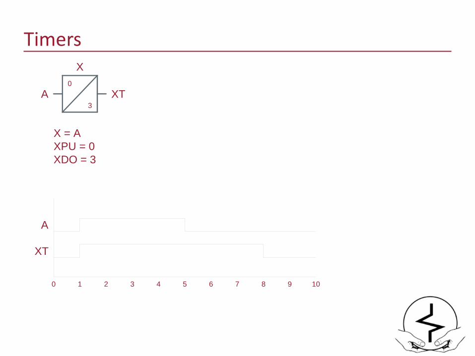
Timers
0
3
X
A XT
X = AXPU = 0XDO = 3
A
XT
10 2 3 4 5 6 7 8 9 10

Timers
2
3
X
A XT
X = AXPU = 2XDO = 3
A
XT
10 2 3 4 5 6 7 8 9 10
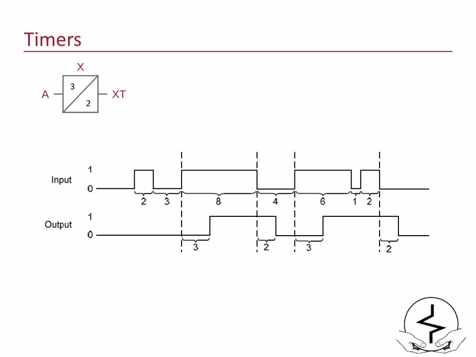
Timers
2
3
X
A XT
3
2
Timers
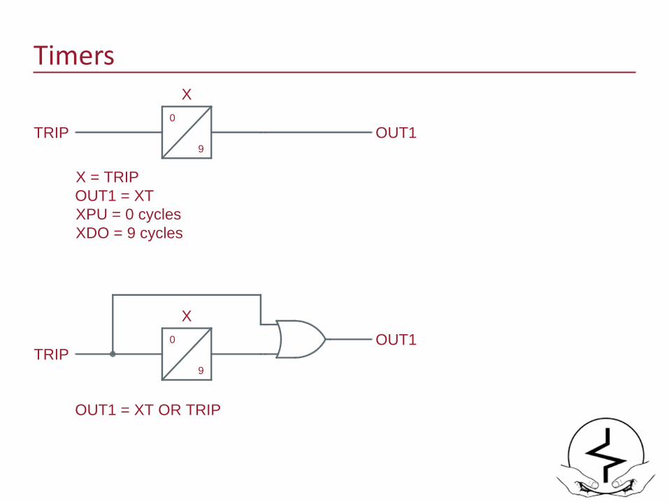
0
9
X
TRIP
OUT1 = XT OR TRIP
OUT1
0
9
X
TRIP
X = TRIPOUT1 = XTXPU = 0 cyclesXDO = 9 cycles
OUT1
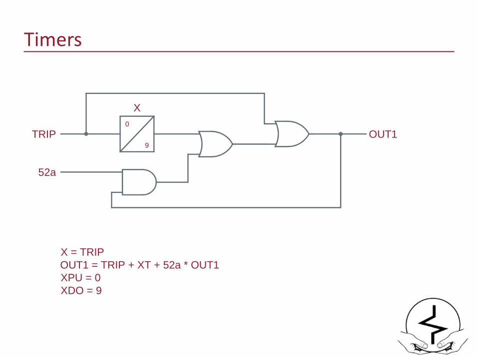
Timers
0
9
X
TRIP OUT1
52a
X = TRIPOUT1 = TRIP + XT + 52a * OUT1XPU = 0XDO = 9
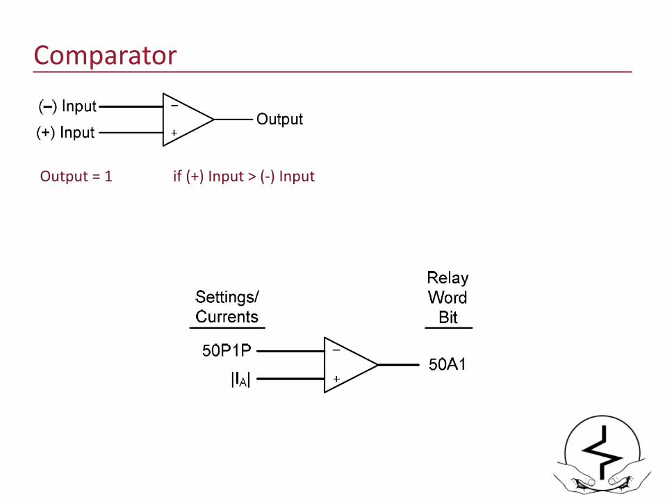
Comparator
Output = 1 if (+) Input > (-) Input
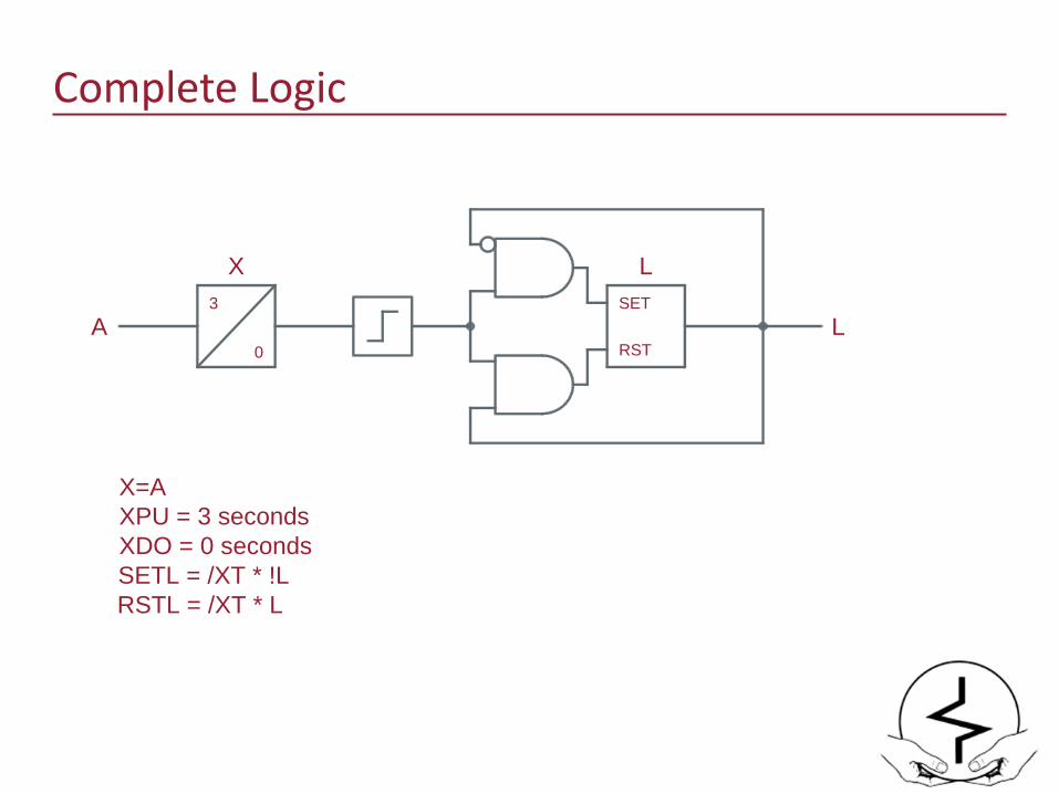
Complete Logic
A L
X=AXPU = 3 secondsXDO = 0 secondsSETL = /XT * !LRSTL = /XT * L
3
0
X LSET
RST
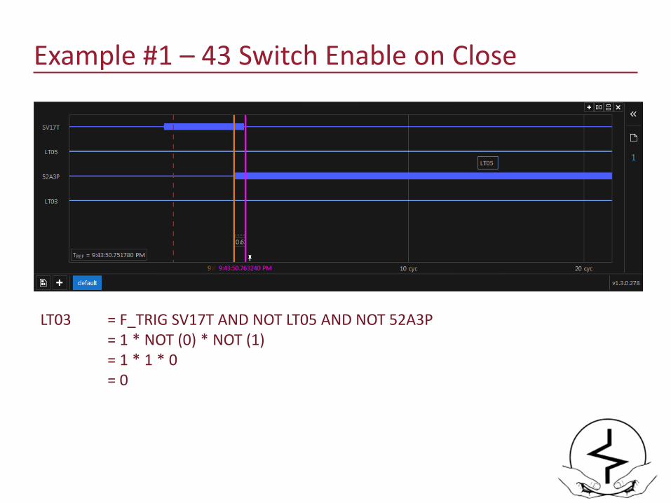
Example #1 – 43 Switch Enable on Close
LT03 = F_TRIG SV17T AND NOT LT05 AND NOT 52A3P= 1 * NOT (0) * NOT (1)= 1 * 1 * 0= 0
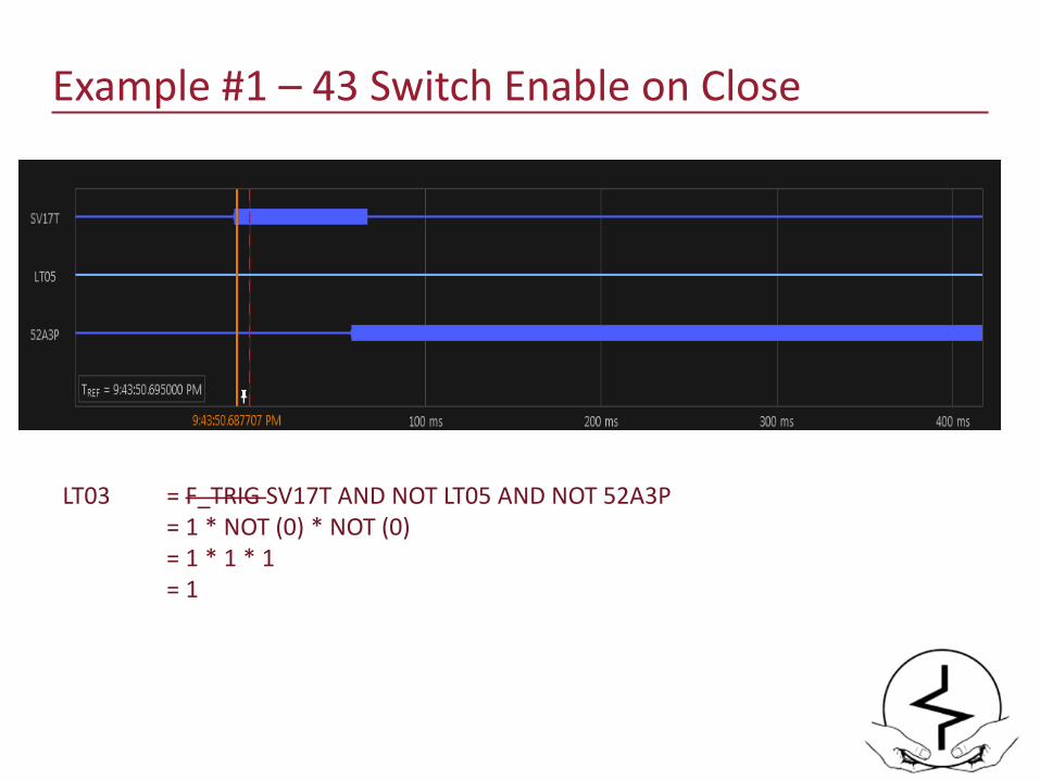
Example #1 – 43 Switch Enable on Close
LT03 = F_TRIG SV17T AND NOT LT05 AND NOT 52A3P= 1 * NOT (0) * NOT (0)= 1 * 1 * 1= 1
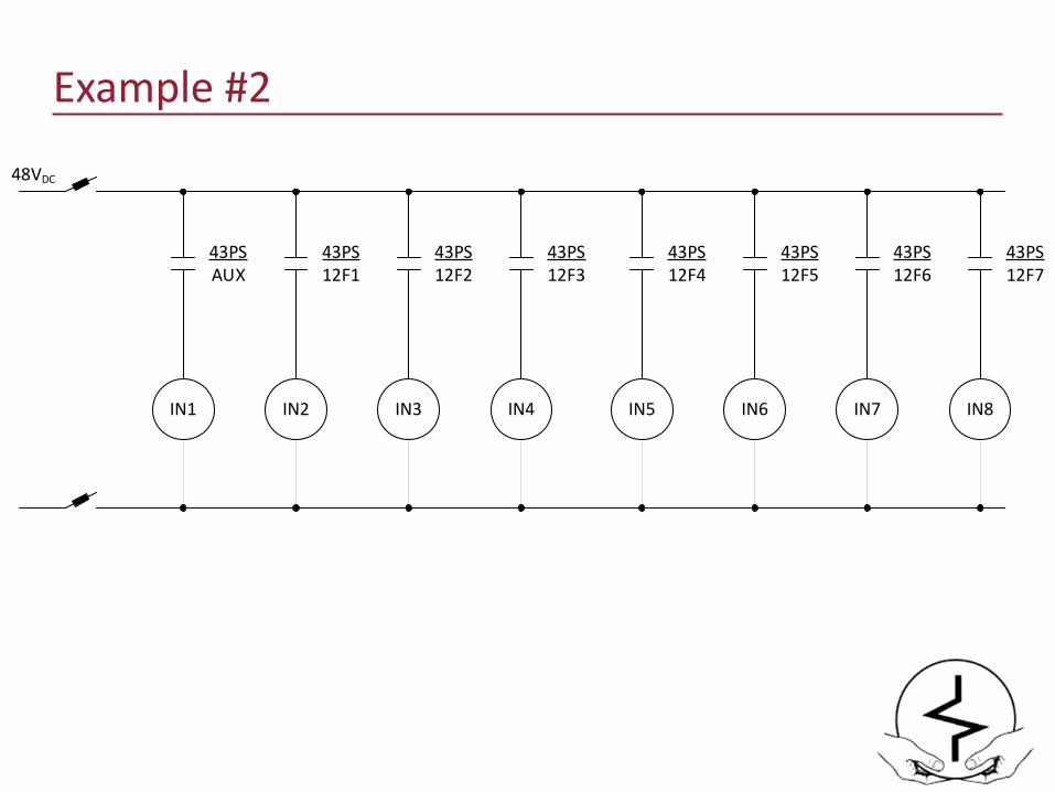
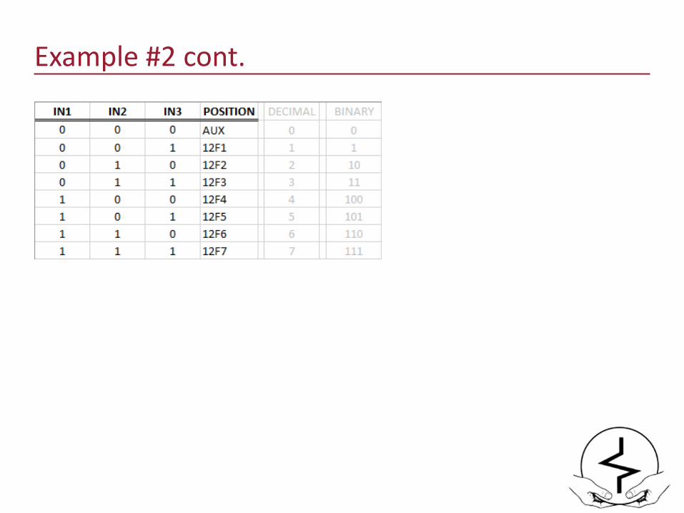
Example #2
IN1
43PSAUX
IN2
43PS12F1
IN3
43PS12F2
IN4
43PS12F3
IN5
43PS12F4
IN6
43PS12F5
IN7
43PS12F6
IN8
43PS12F7
48VDC
Example #2 cont.
Example #2 cont.
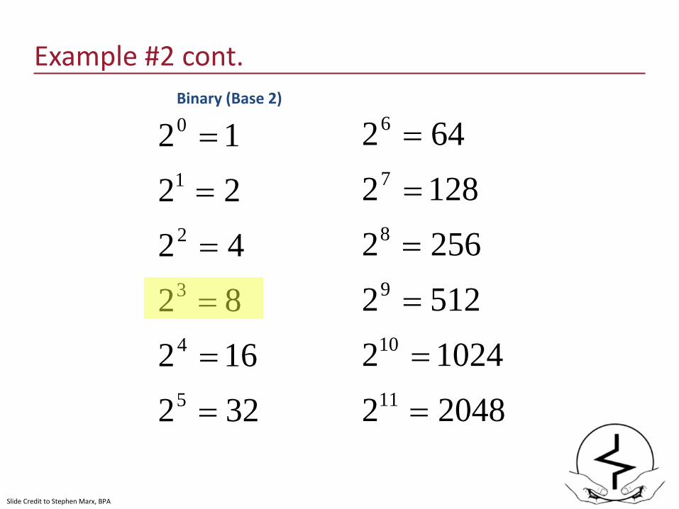
32216282422212
5
4
3
2
1
0
=
=
=
=
=
=
2048210242512225621282642
11
10
9
8
7
6
=
=
=
=
=
=Binary (Base 2)
Slide Credit to Stephen Marx, BPA

Example #2 cont.
953 expressed in Decimal (Base 10)
=953
953350900131051009103105109 012
=++++++
xxxxxx
Slide Credit to Stephen Marx, BPA
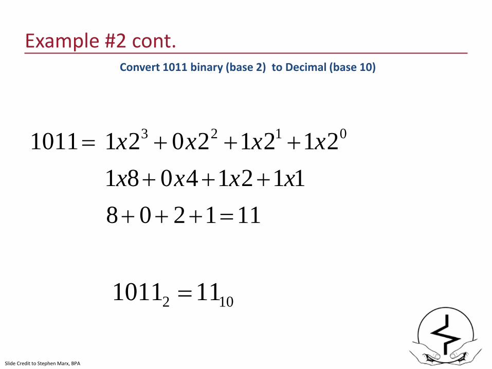
Example #2 cont.
11120811214081
21212021 0123
=++++++
+++xxxx
xxxx
Convert 1011 binary (base 2) to Decimal (base 10)
102 111011 =
=1011
Slide Credit to Stephen Marx, BPA

Example #2 cont.
Courtesy of Electroswitch
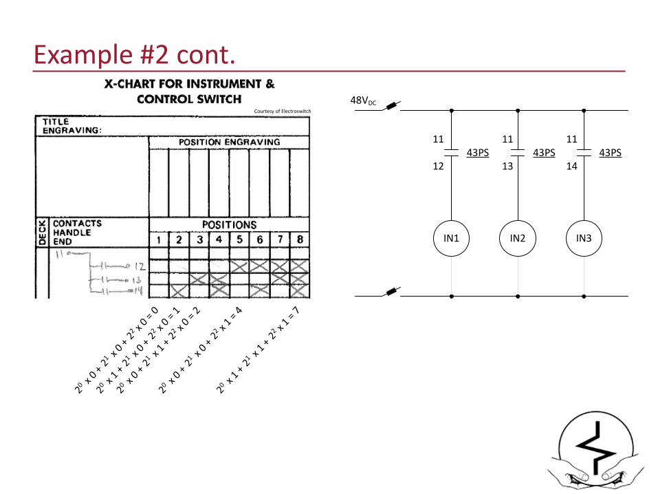
Example #2 cont.
Courtesy of Electroswitch
IN1
43PS
IN2
43PS
IN3
43PS
48VDC
11
12
11
13
11
14
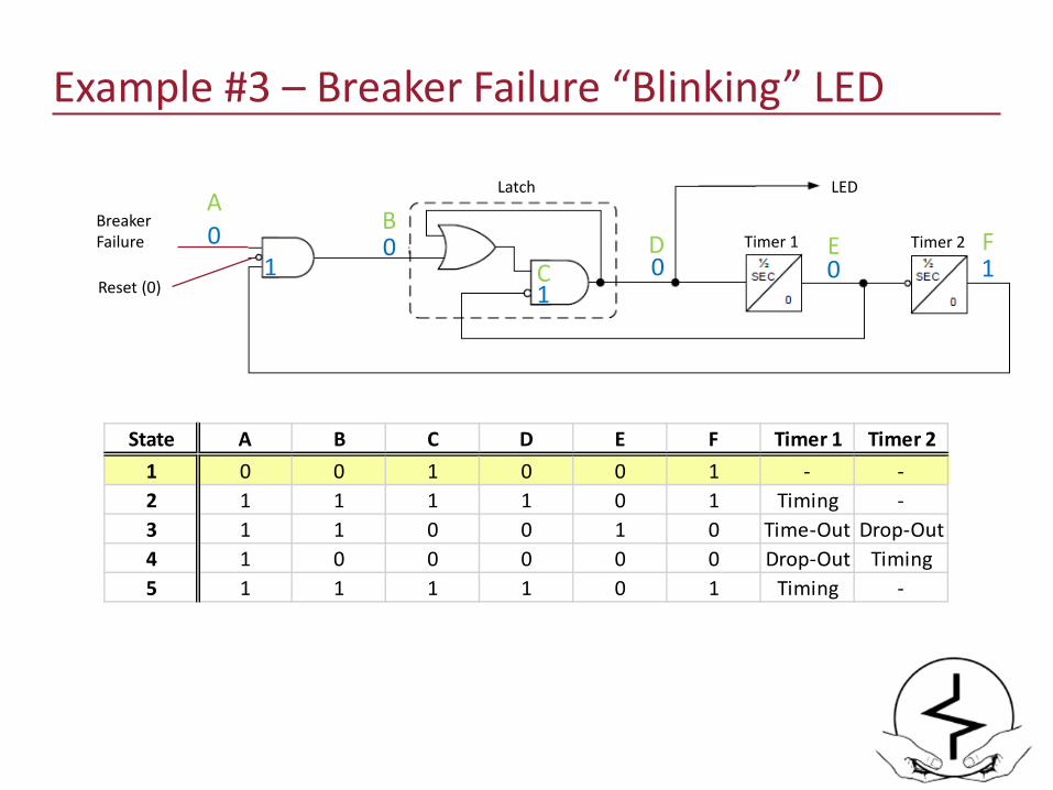
Example #3 – Breaker Failure “Blinking” LED
Breaker Failure
Reset (0)
Latch
00
LED
0 11
Timer 1 Timer 2
10A
B
CD E F
State A B C D E F Timer 1 Timer 21 0 0 1 0 0 1 - -2 1 1 1 1 0 1 Timing -3 1 1 0 0 1 0 Time-Out Drop-Out4 1 0 0 0 0 0 Drop-Out Timing5 1 1 1 1 0 1 Timing -

Example #3 – Breaker Failure “Blinking” LED
Breaker Failure
Reset (0)
Latch
11
LED
0 11
Timer 1 Timer 2
11
Timing
AB
D E F
State A B C D E F Timer 1 Timer 21 0 0 1 0 0 1 - -2 1 1 1 1 0 1 Timing -3 1 1 0 0 1 0 Time-Out Drop-Out4 1 0 0 0 0 0 Drop-Out Timing5 1 1 1 1 0 1 Timing -
C
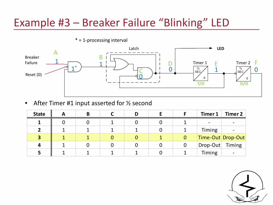
Example #3 – Breaker Failure “Blinking” LED
Breaker Failure
Reset (0)
Latch
10
LED
1 00
• After Timer #1 input asserted for ½ second
Timer 1 Timer 21*
1
T/O D/O
AB
D E F
* = 1-processing interval
State A B C D E F Timer 1 Timer 21 0 0 1 0 0 1 - -2 1 1 1 1 0 1 Timing -3 1 1 0 0 1 0 Time-Out Drop-Out4 1 0 0 0 0 0 Drop-Out Timing5 1 1 1 1 0 1 Timing -
C
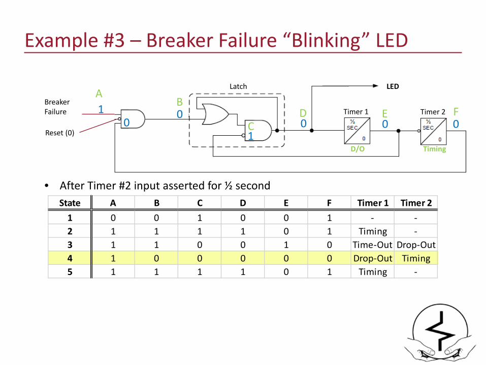
Example #3 – Breaker Failure “Blinking” LED
Breaker Failure
Reset (0)
Latch
00
LED
0 01
• After Timer #2 input asserted for ½ second
Timer 1 Timer 21
D/O Timing
AB
D E F0
State A B C D E F Timer 1 Timer 21 0 0 1 0 0 1 - -2 1 1 1 1 0 1 Timing -3 1 1 0 0 1 0 Time-Out Drop-Out4 1 0 0 0 0 0 Drop-Out Timing5 1 1 1 1 0 1 Timing -
C
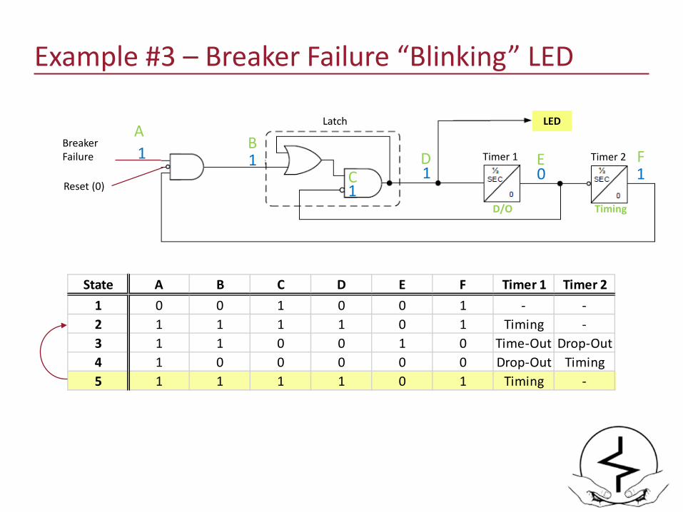
Example #3 – Breaker Failure “Blinking” LED
Breaker Failure
Reset (0)
Latch
11
LED
0 11
Timer 1 Timer 21
D/O Timing
AB
D E F
State A B C D E F Timer 1 Timer 21 0 0 1 0 0 1 - -2 1 1 1 1 0 1 Timing -3 1 1 0 0 1 0 Time-Out Drop-Out4 1 0 0 0 0 0 Drop-Out Timing5 1 1 1 1 0 1 Timing -
C
Recommendations on Testing
• Both positive and negative logic tests
• Understand state of return from power cycle/reset
• Always use the as-left relay settings to test output logic
• All setting changes must be completed first.
• Use end-devices (breaker/disconnect switch staus) whenever possible.
• Question the design engineer!
• Ask for/compare against an Operating Description (if it exists)

Questions?
Kevin Damron, PESr. Protection Engineer – Avista UtilitiesAdjunct Professor – Gonzaga [email protected]