digital multimeter - · pdf filethis intelligent digital multimeter complies with ˜ 1...
TRANSCRIPT

DIGITAL MULTIMETER
USERS MANUAL

CONTENTS SAFETY PRECAUTIONS - - - - - - - - - - - - - - - 1
SAFETY INFORNAMTION - - - - - - - - - - - - - 1
SAFETY SYMBOLS - - - - - - - - - - - - - - - - - - 2
FEATURE - - - - - - - - - - - - - - - - - - - - - - - - - 2
LAYOUT - - - - - - - - - - - - - - - - - - - - - - - - - - - 3
DISPLAY - - - - - - - - - - - - - - - - - - - - - - - - - - 4
SYNOPSES OF MEASUREMENT FUNCTION AND
BUTTON FUNCTION - - - - - - - - - - - - - - - - - - 6
BUTTON FUNCTION TOUR - - - - - - - - - - - - 7
F1 FUNCTION BUTTON - - - - - - - - - - - - - 7
F2 FUNCTION BUTTON - - - - - - - - - - - - - 8
F3 FUNCTION BUTTON - - - - - - - - - - - - - 8
F4 FUNCTION BUTTON - - - - - - - - - - - - - 8
ALARM BUTTON - - - - - - - - - - - - - - - - - 9
SETUP BUTTON - - - - - - - - - - - - - - - - - 10
BUTTON - - - - - - - - - - - - - - - - - - - - 10
RANGE BUTTON - - - - - - - - - - - - - - - - - 11
MAX MIN BUTTON - - - - - - - - - - - - - - - - 12
ENTER HOLD BUTTON - - - - - - - - - - - - 13
REL BUTTON - - - - - - - - - - - - - - - - - - - 14
MEM BUTTON - - - - - - - - - - - - - - - - - - - 15
FUNCTION SWITCH TOUR- - - - - - - - - - - - - - 15
OPERATION - - - - - - - - - - - - - - - - - - - - - - 16
MEASURING VOLTAGE - - - - - - - - - - - 16

MEASURING RESISTANCE - - - - - - - - - 20
MEASURING TEPERATURE - - - - - - - - - 23
MEASURING CURRENT - - - - - - - - - - 23
RS232 DATA INTERFACE - - - - - - - - - - - 26
AUTO POWER OFF FUNCTION - - - - - - - 26
BACKLIGHT - - - - - - - - - - - - - - - - - - - - - 27
LOW VOLTAGE INDICATION - - - - - - - - - - 27
REPLACING THE FUSE - - - - - - - - - - - - 27
REPLACING THE BATTERIES - - - - - - - 28
SPECIFICATION - - - - - - - - - - - - - - - - - 30
ACCESSORY - - - - - - - - - - - - - - - - - - - 33
SAFETY PRECAUTIONS · Read these operation instructions thoroughly and
completely before operating your meter. Pay particular attention to WARNINGS. The instructions

and warnings must be followed. · You must be careful when working with voltages
above 30V AC. Keep fingers behind the probe barriers while measuring.
· Never use the meter to measure voltages that might exceed the allowable maximum input value of any function measurement mode.
· Always inspect your meter and test leads before every use. If any abnormal conditions exist, broken test leads, cracked cases, LCD not reading, etc, do not attempt to take any measurement.
· Never replace the protective fuse inside the instrument with a fuse other than the specified or approved equal fuse. Replace only with same type of fuses. To avoid electrical shock, turn off the instrument and disconnect the test leads and any input signals before replacing the fuses.
· Use the meter with the equipped test leads only to conform to safety requirements. If you need to replace broken test leads, they must be replaced with the same type and electric specification.
· Never touch a voltage source when the test leads are plugged into a current jack.
· Do not expose the instrument to direct sunlight, extreme temperature or moisture.
SAFETY INFORNAMTION This Intelligent digital multimeter complies with
1
IEC1010-1, Protection Class,pollution degree 2 AC 700V. If the instrument is used in a manner not specified, the protection provided by the equipment may be impaired.
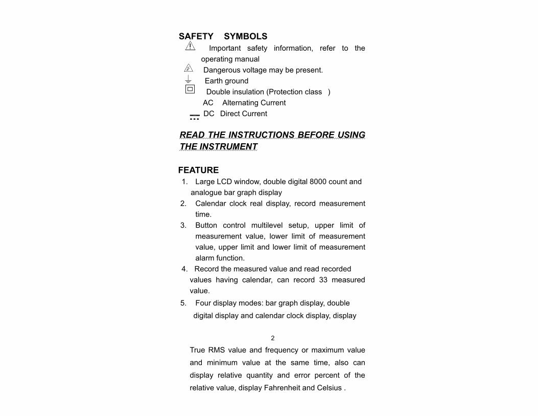
SAFETY SYMBOLS Important safety information, refer to the operating manual
Dangerous voltage may be present. Earth ground
Double insulation (Protection class) AC Alternating Current
DCDirect Current
READ THE INSTRUCTIONS BEFORE USING THE INSTRUMENT
FEATURE 1. Large LCD window, double digital 8000 count and
analogue bar graph display 2. Calendar clock real display, record measurement
time. 3. Button control multilevel setup, upper limit of
measurement value, lower limit of measurement value, upper limit and lower limit of measurement alarm function.
4. Record the measured value and read recorded
values having calendar, can record 33 measured value.
5. Four display modes: bar graph display, double
digital display and calendar clock display, display
2 True RMS value and frequency or maximum value
and minimum value at the same time, also can
display relative quantity and error percent of the
relative value, display Fahrenheit and Celsius .

6. Match PC photo electricity interface and PC windows software, record data and export graph.
LAYOUT
( Figure 1 ) 3
1. RS232 interface 2. LCD 3. 1 button 4. 2 button

5. 3 button 6. 4 button 7. Backlight button 8. RANGE button 9. MAX MIN button 10. ENTER HOLD button 11. SETUP button 12. REL button 13. Function Switch
Used to select measurement mode 14. ALARM button 15. MEM button 16. 10A current input jack 17. mA /1A current input jack 18. COM common jack 19. VHz voltage input jack
DISPLAY
1 Dangerous voltage symbol 2 Battery symbol 3 Bar graphic 4 Digit symbol 5 HOLD symbol 6 Buzzer symbol 7 RMS symbol 8 Voltage/current unit symbol
4
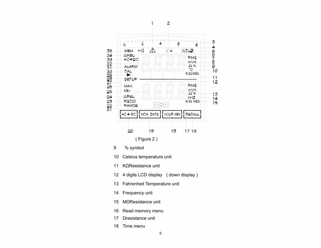
( Figure 2 )
9 % symbol
10 Celsius temperature unit
11 KΩResistance unit
12 4 digits LCD display ( down display )
13 Fahrenheit Temperature unit
14 Frequency unit
15 MΩResistance unit
16 Read memory menu 17 Ωresistance unit
18 Time menu 5

19 Date menu 20 AC/ DC menu 21 4 digit LCD display (display time or date) 22 Range symbol 23 RS232 symbol 24 Relatively symbol 25 Minimum symbol 26 Maximum symbol 27 Setup symbol 28 Decimal point 29 Diode symbol 30 Calibrate symbol 31 Alarm symbol 32 negative symbol 33 AC DC symbol 34 4 digits LCD display up display 35 Save symbol
SYNOPSES OF MEASUREMENT FUNCTION AND BUTTON FUNCTIN
6
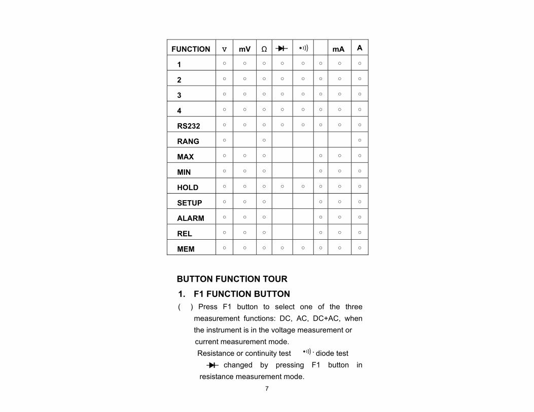
BUTTON FUNCTION TOUR 1. F1 FUNCTION BUTTON ( ) Press F1 button to select one of the three
measurement functions: DC, AC, DC+AC, when the instrument is in the voltage measurement or current measurement mode.
Resistance or continuity test or diode test is changed by pressing F1 button in
resistance measurement mode. 7
FUNCTION V mV Ω mA A
1
2
3
4
RS232
RANG
MAX
MIN
HOLD
SETUP
ALARM
REL
MEM

When the instrument is in the SETUP mode, press F1 button to select the bit of time value or alarm value that you wane to change, the twinkling selected bit move left by each press.
2. F2 FUNCTION BUTTON In the measurement mode, press F2 button to
change clock display mode of the instrument to display the month and the day of current date.
In the SETUP mode, press F2 button to change the time value or alarm value, twinkling selected bit added 1 by each press.
3. F3 FUNCTION BUTTON In the measurement mode, press F3 button to
change clock display mode of the instrument to display the hour and the minute of current time.
In SETUP mode, press F3 button to change the time value or alarm value, twinkling selected bit decrease by each press.
4. F4 FUNCTION BUTTON In measurement mode, press F4 button to read
stored data in the memory, the LCD displays “MEM–n” symbol at first, then displays measuring value. “n” is 1 to 33 serial number in the memory. Press the button to
8
increase the saved serial number, then LCD

display the stored measurement value, press F4 button time after time, the data in memory is displayed circularly.
In SETUP mode, press F4 button to select the bit of the time value or alarm value that you want to change, twinkling selected bit move right by each press.
5. ALARM BUTTON In measurement mode, press ALARM button, then the LCD displays “ALARM” symbol, the meter enters measuring alarm state. There are three alarm modes:
1. HIGH ALARM MODE Use this mode estimate to whether the measurement value exceeds the Alarm Max threshold value. when the measurement value exceeds the Alarm Max threshold value, a continuous beep at low frequency comes out.
2. LOW ALARM MODE Use this mode to estimate whether the measurement value is below the Alarm Min threshold value.
when the measurement value is below the Alarm Min threshold value, a continuous beep
at low frequency comes out. 3. AREA ALARM MODE Use this mode to estimate whether the
9
measurement value is in the area that you set.

When the measurement value exceeds the Alarm Max threshold value or is below the Alarm Min threshold value, a continuous beep at low frequency comes out. Use this mode can measure voltage, current, temperature. when the measurement value exceed the threshold value, the buzzer emits beep. You can also use this mode to sieve the resistance in resistance mode. Press ALARM button again to cancel the alarm mode, the “ALARM” symbol is disappeared on the display.
6. SETUP BUTTON It is setup function button. press SETUP button to set time value or alarm value or alarm mode. Refer to Figure 3.
7. BUTTON
Back light button. press this button to turn backlight on. The backlight turn on over 8 seconds, then the backlight is auto turn off.
10

( Figure 3 )
8. RANGE BUTTON
Select to Autorange mode or manual range mode. When the LCD displays “RANGE”, the meter is in the manual mode; when “RANGE” symbol no display, the meter is in the autorange mode. After the instrument power on, it is in the autorange mode automatically, then press the RANGE button. the meter changes into the manual range mode; press the button again, the range switch once more. When you press the
11

RANGE button for 2 seconds, it return the autorange mode.
9. MAX MIN BUTTON Press this button, the LCD displays “MAX” symbol and maximum value on the second line of the display, press this button again, LCD displays “Min” symbol and minimum value on the same position. (As Figure 4 and Figure 5)
( Figure 4 )
( Figure 5 )
12

When it is not on the MAX or MIN mode, the instrument can automatic record the maximum measurement value and minimum measure- -ment value. To observe maximum value and minimum value, you can press this MAX MIN button to change display. Press and hold down this button for over 2 seconds, the prompts of MAX function or MIN function are disappeared. When you press REL button, the instrument is in REL measurement mode, MAX or MIN function is canceled.
MAXMIN BUTTON FLOW Figure 6
( Figure 6 )
10. ENTER HOLD BUTTON In measurement mode, press ENTER HOLD button to enter the hold data mode, current data is held on the LCD; press this button again to cancel hold data function.
In SETUP mode, press ENTER HOLD button to
13

save the data which you had already set and exit setup mode.
11. REL BUTTON When press REL button at first time, the LCD displays current measurement value on the first line and displays “REL” symbol and relative value on the second line . ( Figure 7 )
( Figure 7 )
( Figure 8 )
14

Press REL button again, the LCD displays percent error of the relative value on the first line, and displays relative measurement value on the second line. ( Figure 8 )
Press REL button time after time, the display change the mode between as Figure 7 and Figure 8. Press this button for over 2 seconds, REL mode is canceled, the instrument return to measurement mode.
When you press the MAX MIN button in REL mode, the instrument automatically enter MAX measurement mode.
12. MEM BUTTON
When you press MEM button in measurement mode, the current measurement value is saved in the meter. The LCD displays “MEM n” for 2 seconds at first, the “n” can be 1 to 33. The instrument can save 33 times at most. If the LCD displays “FULL” symbol, the memory of the instrument is full. If you want to save data again, you must press the SETUP button, then press the MEM button to clear the memory. After that you can save data again.
FUNCTION SWITCH TOUR VHz Voltage Measurement
Range: 800V,80V,8V
15

MV: Voltage Measurement Range: 800mV
Ω: Resistance Measurement, Diode Test and Continuous Test
: Temperature Measurement 80mA: Current Measurement
Range: 80mA A: Current Measurement
Range: 1A, 10A When the current signal is input into the
mA/1A jack, press RANGE button, the LCD displays “mA” symbol, the range is 1A. When the current signal is input into the 10A jack , press RANGE button, the LCD displays “A” symbol, the range is 10A.
OPERATION
1. MEASURING VOLTAGE 1.1 Insert the red and black test leads into the
VHz jack and COM jack respectively. Turn the Function Switch to “V/Hz” or ‘mV”, the LCD displays “DC” symbol, it is in DC voltage measurement mode. ( Figure 9 )
16

( Figure 9 )
1.2 press F1 button, LCD displays “AC” symbol, then it is in AC voltage measurement mode. LCD displays current voltage measuring value on the above line of the LCD, and displays the frequency value of the signal on the below line of the LCD. The extent of the minimum measurement frequency is 50mV.
17

( Figure 10 ) 1.3 Press F1 button again, it is the “DC+AC” symbol
not “AC” symbol on the LCD. The instrument is in AC and DC measurement mode.Figure 11
( Figure 11 ) 1.4 When it is in the voltage measurement mode,
press the MAX MIN button, the instrument can
18

measure and display current measuring value and maximum value or minimum value at one time. ( Figure 12)
( Figure 12 ) 1.5 If you press the REL button, the instrument
can display relative value and percent error of the relative value.( Figure 13 )
1.6 If you had set the ALARM function before measurement, you press the ALARM button, the LCD displays the “ALARM” symbol. When the measurement value exceed the alarm threshold value, the instrument comes out buzzer sound. ( Figure 14 )

19
( Figure 13 )
( Figure 14 ) If you want to cancel the ALARM function, you should press ALARM button again.
2. MEASURING RESISTANCE 2.1 Insert the red and black test leads into the
VHz jack and COM jack respectively. Turn

the function switch to “Ω”, the instrument is
20
in resistance measurement mode. Figure 15
( Figure 15 )
2.2 Press F1 button in turn, the instrument can be in Resistance Measurement or Continuity Test or Diode Test . Figure 16 and Figure 17

21
( Figure 16 )
( Figure 17 ) 2.2 In resistance measurement mode, if you
press the MAX button or the REL button or the ALARM button, the instrument can measure MAX value or Min value or relative

value or enter ALARM function mode. 2.3 Using the REL function and the ALARM
22
function, you can filter a batch of resistance and compare the error, and you can use the equipped PC data record software to record and analyze data.
3. MEASURING TEMPERATURE 3.1 Insert the positive test lead and the negative test
lead of the thermocouple into VHz jack and COM jack respectively. Turn the function switch to “”, the instrument enter the temperature measurement mode. Then the LCD displays Celsius value and displays Fahrenheit value at one time. ( Figure 18 )
( Figure 18 ) 3.2 You can select MAX, Min, REL, ALARM
function in temperature measurement mode, the unit is Celsius in these functions.

4. MEASURING CURRENT
4.1 In the current measurement mode, there is 23
two positions: 80mA and A by turning the function switch. It is one range on the 80mA position; it is two ranges: 10A and 1A on the A position, you can press the RANGE button to switch range. In 1A range, the LCD displays as Figure 19, current signal is input in the mA/1A jack and the COM jack; in 10A range, the LCD displays as Figure 20, current signal is input in the 10A jack and the COM jack.

( Figure 19 ) 24
( Figure 20 ) 4.2 You can press the F1 button to switch DC, AC,
DC+AC mode in current measurement mode. 4.3 The LCD displays frequency value of the
measured current in AC current measurement mode. The minimum extent of current frequency measurement is as following.

RANGE MINIMUM EXTENT
80mA 2mA
1A 20mA
10A 200mA
25 4.4 You can select MAX, Min, REL, ALARM function
in current measurement mode, the operation is the same as voltage measure- -ment mode.
RS232 DATA INTERFACE The instrument can transmit data to PC computer by a RS232 infrared photoelectricity interface in real-time mode. You can connect the RS232 interface to a serial port of PC computer, then install the user data record software into the computer according to the README.TEXT file in the SETUP disk. After that, you can record and print the measured data of the instrument in real-time mode on the WINDOWS. The user data record special software can complete to record, collate, plot, print data in real-time mode. Note: In all measurement mode, the measured data can be transmitted to the PC serial port automatically, but the instrument will stop transmitting in the SETUP mode.
AUTO POWER OFF FUNCTION The instrument has Auto Power OFF function. After no operation for 10 minutes, the instrument will switch to

OFF automatically. By now you can turn the function switch to any position to switch the instrument on.
26
BACKLIGHT When you press the button, the backlight turn ON. After about 8 seconds, the backlight auto turn OFF.
LOW VOLTAGE INDICATION When the batteries is , the LCD displays the “ ” symbol.
REPLACING THE FUSE
WARNING To avoid electrical shock, the instrument must be power off and disconnect the test leads or any input signals before replacing the fuses. Replace only with same type fuses. The mA input terminal is protected by a ‰1A /250V fast blow ceramic fuse. The A input terminal is protected by 10A/ 600V fast blow ceramic fuse.
Use the following procedure to replace the blown fuses of the instrument:
1 Disconnect test leads from the measured circuit, turn the function switch to OFF, remove the test leads from the input jacks.
2 Remove the battery cover. 3 Unscrew the screw on the back cover, and
remove the back cover.

4 Remove the blown fuse, replace with the same size and rating fuses.
5 The mA input terminal is protected by a
27 1A/ 250V fast blow ceramic fuse, the A input terminal is protected by a 10A/600V fast blow ceramic fuse.
6 Make sure the new fuse is centered in the fuse holder.
7 Reinstall the back cover and the screw. 8 Reinstall the battery cover.
REPLACING THE BATTERIES
WARNING To avoid electrical shock , the instrument must be power off and disconnect the lest leads or any input signals before replacing the batteries. Never use the instrument unless the back cover of the instrument is fastened completely. Replace only with same type or rating batteries.
When the LCD displays the “ ” symbol, the batteries must be replaced to maintain proper operation. Use the following procedure to replace the batteries:
1. Remove the test leads from tested circuit, turn the function switch to “OFF”. Remove the test leads from the input jacks.
2. Open the battery cover. 3. Remove the exhausted battery and replace with
new batteries which is the same type or rating. 4. Reinstall the battery cover.

28
Note There is a calendar clock battery in the instrument, the type is CR1220 3V button battery. A new CR1220 battery can be used for about three years. If the clock battery is exhausted, the display of calendar clock on the LCD is deviant. In this case the instrument maybe switch the power to OFF at once when you switch it power on. You must replace a new CR1220 battery now. To check the calendar clock battery, you can press the SETUP button to enter the setup time mode after switching the power to ON. Set the time, then switch the power to OFF; power on the instrument again, if the time is not set, the clock battery is exhausted, you must replace with a new battery. Use the following procedure to replace the clock battery:
1. Disconnect the test leads from the measured circuit, turn the function switch to OFF, remove the test leads from the input jacks.
2. Remove the battery cover. 3. Unscrew the screw on the back cover. 4. Remove the back cover. 5. Remove the exhausted battery, replace a new
battery CR1220. 6. Reinstall the back cover.

29
SPECIFICATION * DC VOLTAGE
RANGE ACCURACY RESOLUTION
800mV ±(0.5%+6dgts) 0.1mV
8V ±(0.5%+6dgts) 0.001V
80V ±(0.5%+6dgts) 0.01V
800V ±(0.5%+6dgts) 0.1V Input Impedance: 10MΩ
Max Input Voltage: 1000V DC or 750V AC ( RMS )
* AC VOLTAGE
RANGE ACCURACY RESOLUTION
800mV ±(1%+8dgts) 0.1mV
8V ±(1%+8dgts) 0.001V
80V ±(1%+8dgts) 0.01V
700V ±(1%+8dgts) 0.1V Input Impedance: 10MΩ
Max Input Voltage: 1000V DC or 750V AC ( RMS )
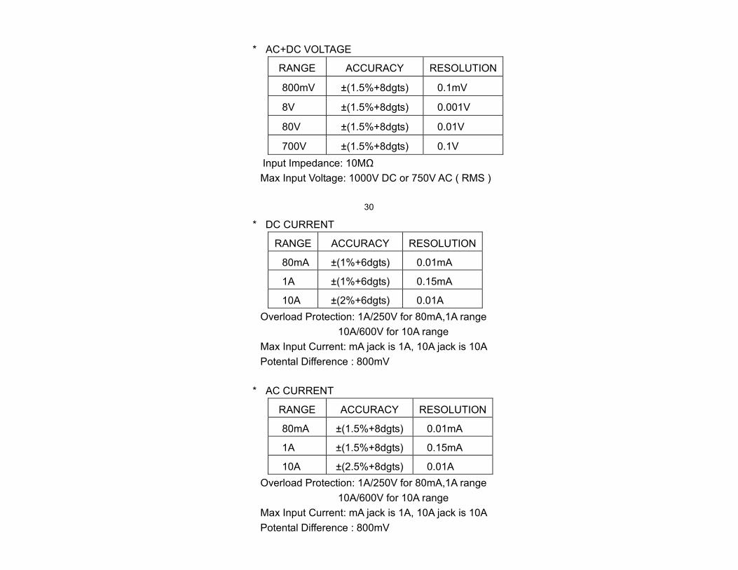
* AC+DC VOLTAGE
RANGE ACCURACY RESOLUTION
800mV ±(1.5%+8dgts) 0.1mV
8V ±(1.5%+8dgts) 0.001V
80V ±(1.5%+8dgts) 0.01V
700V ±(1.5%+8dgts) 0.1V Input Impedance: 10MΩ
Max Input Voltage: 1000V DC or 750V AC ( RMS )
30
* DC CURRENT
RANGE ACCURACY RESOLUTION
80mA ±(1%+6dgts) 0.01mA
1A ±(1%+6dgts) 0.15mA
10A ±(2%+6dgts) 0.01A Overload Protection: 1A/250V for 80mA,1A range
10A/600V for 10A range Max Input Current: mA jack is 1A, 10A jack is 10A Potental Difference : 800mV
* AC CURRENT
RANGE ACCURACY RESOLUTION
80mA ±(1.5%+8dgts) 0.01mA
1A ±(1.5%+8dgts) 0.15mA
10A ±(2.5%+8dgts) 0.01A Overload Protection: 1A/250V for 80mA,1A range
10A/600V for 10A range Max Input Current: mA jack is 1A, 10A jack is 10A Potental Difference : 800mV

* AC+DC CURRENT
RANGE ACCURACY RESOLUTION
80mA ±2.5%+8dgts 0.01mA
1A ±2.5%+8dgts 0.15mA
10A ±3%+8dgts 0.01A Overload Protection: 1A/250V for 80mA,1A range
10A/600V for 10A range Max Input Current: mA jack is 1A, 10A jack is 10A Potental Difference : 800mV
31
* RESISTANCE
RANGE ACCURACY RESOLUTION
800Ω ±(1%+6dgts) 0.1Ω
8kΩ ±(1%+6dgts) 0.001kΩ
80kΩ ±(1%+6dgts) 0.01kΩ
800kΩ ±(1%+6dgts) 0.1kΩ
8MΩ ±(1.5%+6dgts) 0.001MΩ
40MΩ ±(2.5%+8dgts) 0.05MΩ Open Circuit Voltage: 4V Overload Protection: 250V DC or AC (RMS)
* FREQUENCY
RANGE ACCURACY RESOLUTION
10100Hz ±0.5% 0.01Hz
1001000Hz ±0.5% 0.1Hz
110kHz ±0.5% 1Hz

Overload protection: 1000V DC or 750V AC (RMS) Sensitivity 800mV: ≥50mV
8V: ≥500mV 80V: ≥5V 700V: ≥50V
* TEMPERATURE
RANGE ACCURACY RESOLUTION
-50300 ±3 1
3001300 ±1% 1
Overload Protection: 250V DC or AC (RMS)
32 * TESTING CONDITIONS
Frequency Range in voltage measurement mode : 40400Hz Input Impedance : 10MΩ Temperature : 23±3 Humidity : 50%RH±10%
Battery Voltage : 2.5V3V * POWER SUPPLY 2×1.5V AA BATTERIES * DIMENSION SIZE :79mm×190mm×34mm * WEIGHTapprox. 300g * RS232C INTERFACE
ACCESSORY
Users Manual 1 Battery 1.5V AA 2 Test Leads MS3000 1 Thermocouple ( MS3400 ) 1

Leather Sheath 1 Carry Case 1 PC Data Record Software 1 RS232 Cable 1
33

HYS004832