digital panel meters k3ma series user's manual - omron · digital panel meters k3ma series...
TRANSCRIPT

N106-E
1-04K
3MA
Series D
igital P
anel M
etersU
ser’ s Man
ual
K3MA-JProcess Meter
K3MA-LTemperature Meter
K3MA-FFrequency/Rate Meter
Digital Panel Meters
K3MA Series
User’s Manual
INTR
OD
UC
TION
INSTALLATIO
N AN
DC
ON
NEC
TION
APPLIC
ATIO
NEX
AM
PLESIN
ITIAL S
ETTING
OPER
ATIO
NFU
NC
TION
DES
CR
IPTION
TROUBLESHOOTINGG
UID
EA
PPEND
IX

N106-E
1-04K
3MA
Series D
igital P
anel M
etersU
ser’ s Man
ual

I
This User’s Manual provides you with information necessary. For use of the K3MA series of digital panel meters.Please read this manual carefully to ensure correct and efficient use of the product.Keep this manual handy for future reference.
If contemplating using the product in the following environments or for the following equipment, firstcontact a sales representative of the company and then accept responsibility for incorporating into thedesign fail-safe operation, redundancy, and other appropriate measures for ensuring reliability andsafety of the equipment and the overall system.(1) Environments deviating from those specified in this manual(2) Nuclear power control system, traffic (rail car/automobile/aircraft) control system, medical
equipment, amusement equipment, and rescue and security equipment(3) Other equipment that demands high reliability, including those related to the safety of life and
property
About the Content of the Manual(1) Any reproduction, full or in part, of the manual is prohibited without prior written
permission from the company.(2) Descriptions in the manual may be subject to change without notice.(3) Information in the manual has been carefully checked for accuracy. If finding any
suspicious or erroneous descriptions in the manual, however, you are kindly requestedto contact a branch office of the company. In such a case, please let us know the Cat.No. shown on the front cover of the manual.
PREFACE
GENERAL PRECAUTIONS

II
Terms and Conditions Agreement
Warranty, Limitations of Liability
Warranties
● Exclusive Warranty
Omron’s exclusive warranty is that the Products will be free from defects in materialsand workmanship for a period of twelve months from the date of sale by Omron (orsuch other period expressed in writing by Omron). Omron disclaims all other war-ranties, express or implied.
● Limitations OMRON MAKES NO WARRANTY OR REPRESENTATION, EXPRESS ORIMPLIED, ABOUT NON-INFRINGEMENT, MERCHANTABILITY OR FITNESS FORA PARTICULAR PURPOSE OF THE PRODUCTS. BUYER ACKNOWLEDGESTHAT IT ALONE HAS DETERMINED THAT THE PRODUCTS WILL SUITABLYMEET THE REQUIREMENTS OF THEIR INTENDED USE.
Omron further disclaims all warranties and responsibility of any type for claims orexpenses based on infringement by the Products or otherwise of any intellectualproperty right.
● Buyer Remedy Omron’s sole obligation hereunder shall be, at Omron’s election, to (i) replace (in theform originally shipped with Buyer responsible for labor charges for removal orreplacement thereof) the non-complying Product, (ii) repair the non-complying Prod-uct, or (iii) repay or credit Buyer an amount equal to the purchase price of the non-complying Product; provided that in no event shall Omron be responsible for war-ranty, repair, indemnity or any other claims or expenses regarding the Productsunless Omron’s analysis confirms that the Products were properly handled, stored,installed and maintained and not subject to contamination, abuse, misuse or inap-propriate modification. Return of any Products by Buyer must be approved in writingby Omron before shipment. Omron Companies shall not be liable for the suitabilityor unsuitability or the results from the use of Products in combination with any elec-trical or electronic components, circuits, system assemblies or any other materialsor substances or environments. Any advice, recommendations or information givenorally or in writing, are not to be construed as an amendment or addition to theabove warranty.
See http://www.omron.com/global/ or contact your Omron representative for pub-lished information.
Limitation on Liability; Etc
OMRON COMPANIES SHALL NOT BE LIABLE FOR SPECIAL, INDIRECT, INCI-DENTAL, OR CONSEQUENTIAL DAMAGES, LOSS OF PROFITS OR PRODUC-TION OR COMMERCIAL LOSS IN ANY WAY CONNECTED WITH THEPRODUCTS, WHETHER SUCH CLAIM IS BASED IN CONTRACT, WARRANTY,NEGLIGENCE OR STRICT LIABILITY.
Further, in no event shall liability of Omron Companies exceed the individual price ofthe Product on which liability is asserted.

III
Application Considerations
Suitability of Use
Omron Companies shall not be responsible for conformity with any standards,codes or regulations which apply to the combination of the Product in the Buyer’sapplication or use of the Product. At Buyer’s request, Omron will provide applicablethird party certification documents identifying ratings and limitations of use whichapply to the Product. This information by itself is not sufficient for a complete deter-mination of the suitability of the Product in combination with the end product,machine, system, or other application or use. Buyer shall be solely responsible fordetermining appropriateness of the particular Product with respect to Buyer’s appli-cation, product or system. Buyer shall take application responsibility in all cases.
NEVER USE THE PRODUCT FOR AN APPLICATION INVOLVING SERIOUS RISKTO LIFE OR PROPERTY WITHOUT ENSURING THAT THE SYSTEM AS AWHOLE HAS BEEN DESIGNED TO ADDRESS THE RISKS, AND THAT THEOMRON PRODUCT(S) IS PROPERLY RATED AND INSTALLED FOR THEINTENDED USE WITHIN THE OVERALL EQUIPMENT OR SYSTEM.
Programmable Products
Omron Companies shall not be responsible for the user’s programming of a pro-grammable Product, or any consequence thereof.
Disclaimers
Performance Data
Data presented in Omron Company websites, catalogs and other materials is pro-vided as a guide for the user in determining suitability and does not constitute a war-ranty. It may represent the result of Omron’s test conditions, and the user mustcorrelate it to actual application requirements. Actual performance is subject to theOmron’s Warranty and Limitations of Liability.
Change in Specifications
Product specifications and accessories may be changed at any time based onimprovements and other reasons. It is our practice to change part numbers whenpublished ratings or features are changed, or when significant construction changesare made. However, some specifications of the Product may be changed withoutany notice. When in doubt, special part numbers may be assigned to fix or establishkey specifications for your application. Please consult with your Omron’s represen-tative at any time to confirm actual specifications of purchased Product.
Errors and Omissions
Information presented by Omron Companies has been checked and is believed tobe accurate; however, no responsibility is assumed for clerical, typographical orproofreading errors or omissions.

IV
SAFETY PRECAUTIONS
A signal word indicating a potentially hazardous situationwhich, if not avoided, may result in death or serious injury.
A signal word indicating a potentially hazardous situation,if not avoided, may result in minor or moderate injury orproperty damage.
Signal WordsIn this manual, safety notices are divided into WARNING and CAUTION according to the hazard level.As both of WARNING and CAUTION notices contain important information for ensuring safety, besure to observe them.
Warnings
Do not touch live terminals of the product. Doing so may result in electrical shock.
Do not disassemble or touch the inside when the power is tuned on.Doing so may result in electrical shock.
Do not allow pieces of metal or wire clippings to enter the product.Doing so may result in electrical shock, fire, or malfunction.
Perform correct setting of the product according to the application. Failure to do so may cause unex-pected operation of the overall system, resulting in damage to the system or personal injury.
Take appropriate safety measures in case the product malfunctions.Otherwise, a serious accident could occur if a malfunction of the product prevents comparative out-put from being generated.

V
Observe the following precautions to ensure safety.(1) Maintain the power supply voltage within specifications.(2) Use the product within the rated load.(3) Be sure to check each terminal for correct number and polarity before connection.
Incorrect or reverse connection may damage or burn out internal components of the product. (4) Be sure to tighten the terminal screws.
Recommended tightening torque: 0.43-0.58 N·mLoose screws may result in product failure or malfunction.
(5) Do not connect anything to unused terminals.(6) Install a switch or a circuit breaker so that the operator can turn off the power supply without delay
and attach an appropriate label.(7) Do not disassemble, repair, or modify the product.(8) Do not use the product in flammable or explosive atmosphere.
For proper usage of the product:(1) Do not use the product in such an environment that is subject to the following:
• Direct heat radiation from any heat source• Water flooding or oil splashes• Direct sunlight• Dust or corrosive gases (especially, sulfuric or ammonia gas)• Rapid temperature changes• Condensation or icing due to high humidity• Strong vibration or mechanical shock
(2) Do not block heat dissipation from the product, i.e., allow sufficient space for heat dissipation.(3) Be sure that the rated voltage is reached within 2 seconds after the power is turned ON.(4) Conduct aging for at least 15 minutes after turning ON the power for correct measurement.
(For K3MA-L: 30 minutes)(5) To prevent the effect of static electricity, do not touch live terminals or slit areas of the product.(6) Do not apply heavy load to the product. Doing so may deform or deteriorate the product.(7) Do not use paint thinner for cleaning. Use commercially available alcohol.
Installation and connection(1) Mount the product to a panel that is 1 to 8 mm thick.(2) Install the product in a horizontal position.(3) Use crimp-style terminals fit for the screw size.
NOTICE

VI
Noise prevention(1) Install the product as far as possible from devices that generate strong high-frequency fields (such
as high-frequency welders or sewing machines) or surges.(2) Attach surge absorbers or noise filters to nearby devices that generate noise (particularly, motors,
transformers, solenoids, magnet coils, and other devices that have a high inductance component).However, in the case of K3MA-L, do not connect the surge absorber to the input unit fortemperature sensors.
(3) To prevent inductive noise, separate the terminal block wiring for the product from high-voltage orhigh-current power lines. Do not route the wiring for the product in parallel with or tie it in abundle with power lines.Use of separate wiring ducts or shielded cables will also be effective for noise prevention.
<Examples of noise prevention schemes>
(4) When using a power supply noise filter, check that the filter is suitable for the supply voltage andcurrent ratings and then install it as close as possible to the product.
(5) Televisions, radios, or other wireless devices may cause reception interference if placed near theproduct.

VII
For usage of the product for a long time(1) Avoid using the product in an area with temperature or humidity exceeding specifications, or
subject to dew condensation.When installing the product inside a panel, be sure that the temperature around the product (not thetemperature around the panel) is within the specification.The life of parts depends upon the ambient temperature. Higher temperature decreases and lowertemperature increases the life of parts. Therefore, the life can be increased by lowering the insidetemperature of the digital panel meter.
(2) Use or store the product within the specified ambient temperature and humidity ranges.If two or more products are installed close to each other or one is installed on top of another, theinside temperature of the products may be elevated due to heat generation by products themselves,resulting in decreased life of the products. In such cases, conduct forced cooling, for example, byusing a fan to ventilate the product.
(3) Since the life of output relay depends largely upon the capacity and condition of switching, be sureto take the actual conditions of usage into consideration and to use it within the rated load and thetimes of its electrical life.Using it exceeding its life may cause welding of contact points or burning.

VIII
This manual uses the following alphabetic characters for setting data.
a b c d e f g h i j k l m
A B C D E F G H I J K L M
n o p q r s t u v w x y z
N O P Q R S T U V W X Y Z
Alphabetic Characters for Setting Data

Table of Contents
PREFACE ......................................................................................................IGENERAL PRECAUTIONS .........................................................................I
SAFETY PRECAUTIONS ............................................................................IV
NOTICE .........................................................................................................V
Alphabetic Characters for Setting Data ..........................................................VIII
Table of Contents ...........................................................................................IX
CHAPTER 1 INTRODUCTION ...................................................1-11-1 Main Features of the K3MA ..........................................................................1-2
1-2 Model Number Legend ..................................................................................1-4
1-3 I/O Circuit ......................................................................................................1-5
1-4 Parts Name and Function ...............................................................................1-7
CHAPTER 2 INSTALLATION AND CONNECTION ....................2-12-1 Installation ......................................................................................................2-2
2-2 I/O Terminal Connections ..............................................................................2-4
CHAPTER 3 APPLICATION EXAMPLES ...................................3-13-1 Monitoring the Liquid Level (K3MA-J) ........................................................3-2
3-2 Monitoring the Internal Pressure of a Tank (K3MA-J) ..................................3-4
3-3 Monitoring the Temperature of an Industrial Furnace (K3MA-L) ................3-6
3-4 Monitoring the Feed Speed of a Conveyer (K3MA-F) ..................................3-8
3-5 Monitoring the Rotational Speed by Monitor Output of an Inverter (K3MA-F) ..3-10
CHAPTER 4 INITIAL SETTING ..................................................4-14-1 K3MA-J (Process meter) ................................................................................4-2
4-2 K3MA-L (Temperature meter) .......................................................................4-4
4-3 K3MA-F (Frequency/Rate meter) ..................................................................4-6
CHAPTER 5 OPERATION ..........................................................5-15-1 Levels .............................................................................................................5-2
5-2 Moving among Levels ....................................................................................5-3
5-3 Parameters ......................................................................................................5-5
5-4 Set Values .......................................................................................................5-6
5-5 Viewing and Changing OUT Set Values ........................................................5-7
5-6 Setting/Releasing the Forced-zero Operation (K3MA-J) ..............................5-9
5-7 Displaying/Resetting the MAX/MIN Value ...................................................5-10
5-8 Specifying the Temperature Input Correction Value (K3MA-L) ...................5-11
5-9 Key Protect Setting ........................................................................................5-12
5-10 Selecting an Input Type (K3MA-J/K3MA-L) ................................................5-14
5-11 Selecting an Input-pulse Frequency (K3MA-F) ............................................5-16
IX

5-12 Specifying the Scaling Factor (K3MA-J) ......................................................5-17
5-13 Specifying the Scaling Factor (K3MA-F) ......................................................5-19
5-14 Specifying the Decimal Point Position (K3MA-J/K3MA-F) .........................5-22
5-15 Specifying the Temperature Unit (K3MA-L) ................................................5-23
5-16 Selecting a Comparative Output ....................................................................5-24
5-17 Clearing All Parameters .................................................................................5-25
5-18 Specifying the Number of Measurements for Averaging ...............................5-26
5-19 Specifying the Hysteresis ...............................................................................5-27
5-20 Specifying the Auto-zero Time (K3MA-F) ...................................................5-28
5-21 Specifying the Start-up Compensation Time (K3MA-F) ...............................5-30
5-22 Specifying the Zero-limit (K3MA-J) .............................................................5-31
5-23 Changing the Display Color ...........................................................................5-33
5-24 Changing the Display Auto-return Time ........................................................5-34
5-25 Changing the Move-to-Protect-Level Time ...................................................5-35
CHAPTER 6 FUNCTION DESCRIPTION...................................6-16-1 Measurement (K3MA-J) ................................................................................6-2
6-2 Measurement (K3MA-L) ...............................................................................6-5
6-3 Measurement (K3MA-F) ...............................................................................6-6
6-4 Average Processing ........................................................................................6-10
6-5 Comparative Output .......................................................................................6-11
6-6 Hysteresis .......................................................................................................6-12
6-7 Display Color Change ....................................................................................6-13
CHAPTER 7 TROUBLESHOOTING GUIDE ..............................7-17-1 Indication of Error ..........................................................................................7-2
7-2 Troubleshooting Table ....................................................................................7-3
APPENDIX ...................................................................................A-1Specifications ..................................................................................................A-2
Parameter List .................................................................................................A-5
X

1-1
CHAPTER 1
INTRODUCTION
This chapter provides an overview and parts name of the product.
1-1 Main Features of the K3MA ..........................................................................1-2
1-2 Model Number Legend ..................................................................................1-4
1-3 I/O Circuit ......................................................................................................1-5Input Circuit Diagrams/Output Circuit Diagrams
1-4 Parts Name and Function ...............................................................................1-7

INTR
ODUC
TION
CHAPTER 1 INTRODUCTION
1-1 Main Features of the K3MAThe K3MA is a digital panel meter that is capable of converting an input signal into adigital value and displaying it on the main indicator. The main features of the product include the following.
Measurement This feature measures an input signal and displays it as a digital value.
The input signal to be measured by each type is as follows.
Scaling This feature converts an input signal into adesired physical value.
(Only K3MA-J/F) For example, when a pressure sensor isconnected, in which a current range of 4-20mA corresponds to a pressure range of 0-100kPa, the readout for the input of 4 mA isconverted into "0" and that for the input of 20mA is converted into "100" (kPa). SinceScaling converts an input signal as a value ofcurrent into a unit (kPa) that is used in thesystem, it will enable you to get the valueintuitively.
1-2

INTRODUCTION
1-1 Main Features of the K3MA
Comparative Output This feature compares a scaled value (measurement value) with a programmed OUTset value and produces output according to the comparison result.
This is useful in monitoring various systems for malfunction or determining whetherproducts are within acceptance limits.
Three types of comparative outputs are available: those produced at the OUT upper-limit value, the OUT lower-limit value, and both the OUT values.
Forced-zero This feature shifts a process value to zero, and can be used to evaluate and display thedeviation of a process value from a reference value.
Display Color Change In the example shown below, the display color is programmed so that it changes fromgreen to red when a comparative output turns ON. The display color can also beprogrammed so that it is fixed to "red" or "green".
*As for K3MA-L-C, only one reference value can be set.*With models that do not have comparative outputs, the display color cannot be
changed according to comparisons with a reference value.
(Only K3MA-J-A2, K3MA-F-A2,
and K3MA-L-C)
(Only K3MA-J-A2, K3MA-F-A2,
and K3MA-L-C)
1-3

INTR
ODUC
TION
CHAPTER 1 INTRODUCTION
1-2 Model Number Legend
K3MA- - AC100-240V(1) (2) (3) (4)
Model name
Input type
Output type
Power supply
Symbol Description
K3MA Digital Panel MeterK3MA Series
Symbol Description
J DC voltage/Current inputL Thermocouple/Resistance ther-
mometer inputF Pulse input
Symbol Description
None Not availableC Relay contact output (1c)
A2 Relay contact output (1a × 2)
Symbol Description
AC100-240V 100 to 240 VAC (50/60 Hz)AC/DC24V 24 VAC (50/60 Hz)
24 VDC (Non-polar)
1-4

INTRODUCTION
1-3 I/O Circuit
1-3 I/O CircuitInput Circuit Diagrams
Analog Input
Pulse Input
1-5

INTR
ODUC
TION
CHAPTER 1 INTRODUCTION
Output Circuit Diagrams
Contact Output
Internal Block Diagram
1-6

INTRODUCTION
1-4 Parts Name and Function
1-4 Parts Name and Function
Name Function
Main indicator Displays a process value, parameter code, or set value.
Operation indicator sections
1(Comparative output 1)
Is on when comparative output 1 is on, and off when com-parative output 1 is off.
2(Comparative output 2)
Is on when comparative output 2 is on, and off when com-parative output 2 is off. (Only K3MA-J/K3MA-F.)
SV(Set value)
Stays on while a set value is displayed or being changed, andoff at all other times.
Max(MAX value)
Stays on while a MAX value is displayed, and off at all othertimes.
Min(MIN value)
Stays on while a MIN value is displayed, and off at all othertimes.
T(Teaching)
Stays on while a set value that can be taught is displayed, andblinks during teaching. Stays off at all other times. (OnlyK3MA-J/K3MA-F)
Z(Forced-zero)
Is on when zero-shifting by forced-zero operation is active.Turns off when forced-zero operation is canceled. (OnlyK3MA-J)
Level indicator Indicates the current level.
MAX/MIN key Is used to select current value, MAX value, or MIN value forindication and to reset MAX/MIN value.
Level key Is used to change one level to another. Mode key Is used to select a parameter to be displayed.
Shift key
Is used to check the set value of a parameter or enter thechange state when the parameter is displayed.Is used to shift the figure of the set value when it is in thechange state.
Up keyIs used to change the set value in the change state.Is used to execute or cancel the forced-zero operation when aprocess value is displayed. (Only K3MA-J)
1-7


2-1
CHAPTER 2
INSTALLATIONAND CONNECTION
This chapter describes how to install and connect the product before turning the poweron.
2-1 Installation ......................................................................................................2-2Dimensions/Panel Cutout Dimensions/Installation Procedure/Visibility of LCD
2-2 I/O Terminal Connections ..............................................................................2-4Terminal Arrangement /Terminal Connection

INST
ALLA
TION
AND
CO
NNEC
TION
CHAPTER 2 INSTALLATION AND CONNECTION
2-1 InstallationDimensions
Panel Cutout Dimensions
Fit the product into a rectangular panel cutout, put the adapter in the fixing grooves onthe left and right surfaces of the rear case, and push the product until the gap betweenthe product and the panel surface is minimized.
2-2
INSTALLATION AND CONNECTION
2-1 Installation
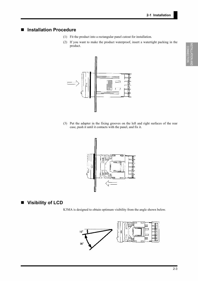
Installation Procedure(1) Fit the product into a rectangular panel cutout for installation.(2) If you want to make the product waterproof, insert a watertight packing in the
product.
(3) Put the adapter in the fixing grooves on the left and right surfaces of the rearcase, push it until it contacts with the panel, and fix it.
Visibility of LCDK3MA is designed to obtain optimum visibility from the angle shown below.
2-3

INST
ALLA
TION
AND
CO
NNEC
TION
CHAPTER 2 INSTALLATION AND CONNECTION
2-2 I/O Terminal Connections
Terminal Arrangement
Terminal No. Name Description Applicable model
A1-A2 Operationpower supply Operation power supply terminals All models
B5-B6 Sensor powersupply Sensor power supply terminals K3MA-F
E1-E3E2-E3 Comparative
output Provides comparative output.K3MA-J-A2K3MA-F-A2
E1/E3-E2 K3MA-L-CE4/E6-E5
Input
Voltage /current analog terminals K3MA-J
E4-E5-E6 Thermometer/resistance thermometer ter-minals K3MA-L
E4/E6-E5 Open collector pulse/voltage pulse inputdevice terminals K3MA-F
K3MA-J-A2/K3MA-F-A2 K3MA-L-C
2-4

INSTALLATION AND CONNECTION
2-2 I/O Terminal Connections
Terminal ConnectionUse crimp contact type terminals as shown below.
Power Supply
Connect the following power supply to terminals A1 and A2.100-240 VAC 50/60 Hz 6 VA24 VAC/DC 50/60 Hz 4.5 VA / 4.5 W (Non-polar)
Note that, when turned on, the product will require the operation power supply to havemore supply capacity than rated. If multiple products are used, the power supply mustbe able to afford to supply power to the products.
Sensor Power Supply (Only K3MA-F)
The following sensor power supply can be supplied from terminals B5 and B6.12VDC 40 mA
Comparative Output
Comparative output is output to terminals E1-E3.Configuration of contact point is as follows.
K3MA-J-A2/K3MA-F-A2: 1a × 2K3MA-L-C: 1c
Connect load within specifications.The electrical life of the relay is 100,000 times.
K3MA-J-A2/K3MA-F-A2 K3MA-L-C
2-5
INST
ALLA
TION
AND
CO
NNEC
TION
CHAPTER 2 INSTALLATION AND CONNECTION
Input
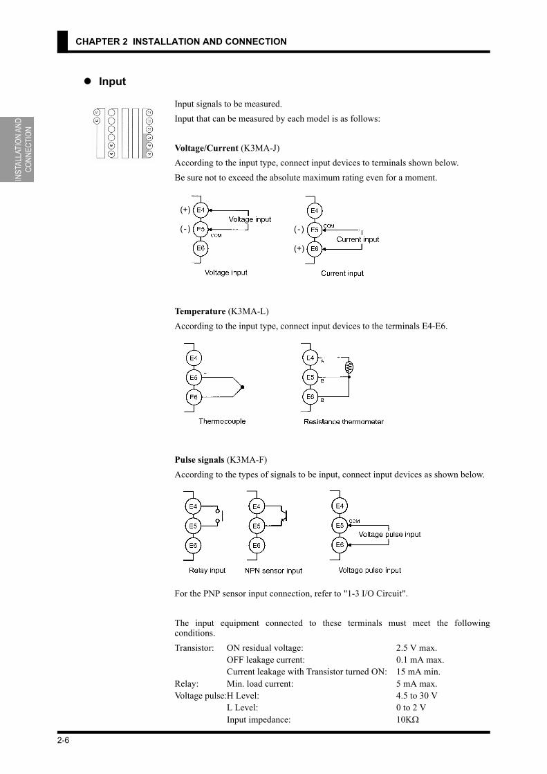
Input signals to be measured.Input that can be measured by each model is as follows:
Voltage/Current (K3MA-J)According to the input type, connect input devices to terminals shown below.Be sure not to exceed the absolute maximum rating even for a moment.
Temperature (K3MA-L)According to the input type, connect input devices to the terminals E4-E6.
Pulse signals (K3MA-F)According to the types of signals to be input, connect input devices as shown below.
For the PNP sensor input connection, refer to "1-3 I/O Circuit".
The input equipment connected to these terminals must meet the followingconditions.Transistor: ON residual voltage: 2.5 V max.
OFF leakage current: 0.1 mA max.Current leakage with Transistor turned ON: 15 mA min.
Relay: Min. load current: 5 mA max.Voltage pulse:H Level: 4.5 to 30 V L Level: 0 to 2 V Input impedance: 10KΩ
(+)
( - ) ( - )
(+)
2-6

3-1
CHAPTER 3
APPLICATIONEXAMPLES
This chapter shows some examples of product applications.
3-1 Monitoring the Liquid Level (K3MA-J) ........................................................3-2
3-2 Monitoring the Internal Pressure of a Tank (K3MA-J) ..................................3-4
3-3 Monitoring the Temperature of an Industrial Furnace (K3MA-L) ................3-6
3-4 Monitoring the Feed Speed of a Conveyer (K3MA-F) ..................................3-8
3-5 Monitoring the Rotational Speed by Monitor Output of an Inverter (K3MA-F) ...3-10

APPL
ICAT
ION
EXAM
PLES
CHAPTER 3 APPLICATION EXAMPLES
3-1 Monitoring the Liquid Level (K3MA-J)
Application
• K3MA-J monitors the liquid level.• Using an ultrasonic displacement sensor, E4PA-LS600-M1, the distance to the
liquid level is detected. (When the distance is 800-6000 mm, the output of the E4PA-LS600-M1 is 4-20mA.)
• The unit of indicated values by the K3MA-J is "m", and the values are indicatedto three decimal places.
• Four measurements are averaged for stable indication.• Since the liquid can not be completely discharged, the liquid level less than 0.05
m is always indicated as 0 m.• When the liquid level reaches 4.5 m, the comparative output 1 is turned ON.• When the liquid level decreases to 0.5 m, the comparative output 2 is turned ON.
Wiring
3-2

APPLICATION EXAMPLES
3-1 Monitoring the Liquid Level (K3MA-J)
Parameter Setting • The scaling is set as follows.
INP1: 4.00DSP1: 5200INP2: 20.00DSP2: 0Position of decimal point: \\.\\\
• The times of measurements for averaging is set to 4.• The zero-limit is turned ON and the zero-limit value is set to 50.• Comparative output 1 is used to generate an upper-limit signal action and the
OUT upper-limit value is set to "4.500 m".• Comparative output 2 is used to generate a lower-limit signal action and the OUT
lower-limit value is set to "0.500 m".
For details of parameters, refer to "CHAPTER 5 OPERATION".The analog output characteristic mode of the sensor is set to "decrease". For details onsensor setting, refer to the Operation Manual for the sensor E4PA.
Operation
• When the liquid level reaches 4.5 m, comparative output 1 is output.• When the liquid level decreases to 0.5 m, comparative output 2 is output.
Level Parameter Set value
Initial setting
in-t 4-20
inp.1 4.00
dsp.1 5200
inp.2 20.00
dsp.2 0
dp \\.\\\
out1.t hi
out2.t lo
Advanced-function setting
avg 4
z-lim on
lim-p 50
Operation setting
out1 4.500
out2 0.500
3-3

APPL
ICAT
ION
EXAM
PLES
CHAPTER 3 APPLICATION EXAMPLES
3-2 Monitoring the Internal Pressure of a Tank (K3MA-J)
Application
• The K3MA-J monitors the internal pressure of a tank.• The internal pressure of the tank is measured with a pressure sensor E8AA-M10.
(When the pressure is 0-980 kPa, current of 4-20 mA is generated.)• The unit of indicated values by the K3MA-J is "kPa", and the values are indi-
cated to one tenth’s.• When the internal pressure of the tank reaches 550 kPa, comparative output 1 is
turned ON.• When the internal pressure of the tank decreases to 100 kPa, comparative output
2 is turned ON.
Wiring
3-4

APPLICATION EXAMPLES
3-2 Monitoring the Internal Pressure of a Tank (K3MA-J)
Parameter Setting • The scaling is set as follows.
INP1: 4.00DSP1: 0INP2: 20.00DSP2: 9800Position of decimal point: \\\\.\
• Comparative output 1 is used to generate an upper-limit signal action and theOUT upper-limit value is set to "550.0 kPa".
• Comparative output 2 is used to generate a lower-limit signal action and the OUTlower-limit value is set to "100.0 kPa".
For details of parameters, refer to "CHAPTER 5 OPERATION".
Operation
• When the internal pressure of the tank reaches 550.0 kPa, comparative output 1is turned ON.
• When the internal pressure decreases to 100.0 kPa, comparative output 2 isturned ON.
Level Parameter Set value
Initial setting
in-t 4-20
inp.1 4.00
dsp.1 0
inp.2 20.00
dsp.2 9800
dp \\\\.\
out1.t hi
out2.t lo
Operation setting
out1 550.0
out2 100.0
3-5

APPL
ICAT
ION
EXAM
PLES
CHAPTER 3 APPLICATION EXAMPLES
3-3 Monitoring the Temperature of an Industrial Furnace (K3MA-L)
Application
• The K3MA-L monitors the temperature of an industrial furnace.• The internal temperature of the furnace is measured with a thermocouple E52-
PR.(The temperature range to be measured by E52-PR is 0-1,400 °C.)
• The unit of indicated values by the K3MA-L is "°C".• When the internal temperature of the furnace reaches 1000 °C or lower than 800
°C, comparative output 1 is turned ON.
Wiring
3-6

APPLICATION EXAMPLES
3-3 Monitoring the Temperature of an Industrial Furnace (K3MA-L)
Parameter Setting • The input type is set to 16 (R element).
• The unit of temperature is set to "°C".• Comparative output 1 is used as outside-the-range signal action, and the OUT
upper-limit value is set to "1000°C" and the OUT lower-limit value is set to"800°C".
For details of parameters, refer to "CHAPTER 5 OPERATION".
Operation
• When the internal temperature reaches 1000 °C or lower than 800 °C, compara-tive output 1 is turned ON.
Level Parameter Set value
Initial settingin-t 16
d-u c
out1.t hi-lo
Operation setting
out1.h 1000
out1.l 800
3-7

APPL
ICAT
ION
EXAM
PLES
CHAPTER 3 APPLICATION EXAMPLES
3-4 Monitoring the Feed Speed of a Conveyer (K3MA-F)
Application
• The K3MA-F monitors the feed speed of a conveyer.• Two rollers with a diameter of 0.1 m are used for the conveyer.• A gear to detect the speed of rotation is attached to the axis of one roller and its
rotation is converted into pulse signals by a proximity switch E2E-X5E1.• The unit of indicated values by the K3MA-F is "m/min" and the values are indi-
cated to one tenth’s.• When the speed reaches 22.0 m/min, comparative output 1 is turned ON.• When the speed decreases to 18.0 m/min, comparative output 2 is turned ON.
Wiring
3-8

APPLICATION EXAMPLES
3-4 Monitoring the Feed Speed of a Conveyer (K3MA-F)
Parameter Setting • The scaling is set as follows.
INP: 100DSP: 18850Position of decimal point: \\\\.\
(Calculation of scaling value)Peripheral velocity D is expressed by the next equation.
Peripheral velocity D (m/min) = f×60×d×π
f: Frequency (Hz)d: Roller diameter (m)
The scaling factor (60×d×π) is calculated and multiplied by 10 to indicate down toone tenth’s. The value obtained is 188.496. The scaling factor is set to a larger value to minimize the errors.(INP is set to "100" and DSP is set to "18850.")
• Comparative output 1 is used to generate an upper-limit signal action and theOUT upper-limit value is set to "22.0 m/min."
• Comparative output 2 is used to generate an lower-limit signal action and theOUT lower-limit value is set to "18.0 m/min."
For details of parameters, refer to "CHAPTER 5 OPERATION".
Operation
• When the feed speed reaches 22.0 m/min, comparative output 1 is turned ON.• When the feed speed decreases to 18.0 m/min, comparative output 2 is turned
ON.
Level Parameter Set value
Initial setting
p-fre 30
inp 100
dsp 18850
dp \\\\.\
out1.t hi
out2.t lo
Operation setting
out1 22.0
out2 18.0
3-9

APPL
ICAT
ION
EXAM
PLES
CHAPTER 3 APPLICATION EXAMPLES
3-5 Monitoring the Rotational Speed by Monitor Output of an Inverter (K3MA-F)
Application
• The K3MA-F monitors the rotational speed by monitor output of an inverter.• The monitor output of the inverter produces a voltage pulse proportional to the
rotational speed of the motor. When the rotational speed of the motor is 60 rps, itproduces 1440 Hz.
• The unit of indicated values by the K3MA-F is "rpm".• When the rotational speed reaches 3000 rpm, comparative output 1 is turned ON.• When the rotational speed decreases to 2000 rpm, comparative output 2 is turned
ON.
Wiring
3-10

APPLICATION EXAMPLES
3-5 Monitoring the Rotational Speed by Monitor Output of an Inverter (K3MA-F)
Parameter Setting • The input type is set to 5K.
• The scaling is set as follows.INP: 1440DSP: 3600Position of decimal point: \\\\\
(Calculation of scaling factor)Since 60 rps can be converted into 3600 rpm, the scaling is set in such a way that aninput of 1440 Hz is indicated as 3600 rpm.
• Comparative output 1 is used to generate an upper-limit signal action and theOUT upper-limit value is set to "3000 rpm".
• Comparative output 2 is used to generate a lower-limit signal action and the OUTlower-limit value is set to "2000 rpm".
For details of parameters, refer to "CHAPTER 5 OPERATION".
Operation
• When the rotational speed reaches 3000 rpm, comparative output 1 is turned ON.• When the rotational speed decreases to 2000 rpm, comparative output 2 is turned
ON.
Level Parameter Set value
Initial setting
p-fre 5k
inp 1440
dsp 3600
dp \\\\\
out1.t hi
out2.t lo
Operation setting
out1 3000
out2 2000
3-11


4-1
CHAPTER 4
INITIAL SETTING
The K3MA includes models for Process meter, Temperature meter, and Frequency/Rate meter Device.This chapter explains the flow of initial setting for each of these models.Settings related to comparative outputs can be made only for models that havecomparative outputs (K3MA-J-A2, K3MA-F-A2, and K3MA-L-C).
4-1 K3MA-J (Process meter) ................................................................................4-2
4-2 K3MA-L (Temperature meter) .......................................................................4-4
4-3 K3MA-F (Frequency/Rate meter) ..................................................................4-6

INIT
IAL S
ETTI
NG
CHAPTER 4 INITIAL SETTING
The "input type", "scalingfactor", and "decimal pointposition" should be set in thisorder.Otherwise, auto-initializationof parameters may result in afailure in parameter setting.If you specify the scalingfactor and then the input type,the scaling factor is initializedautomatically.
4-1 K3MA-J (Process meter)The following example shows the flow of initial setting for K3MA-J.
Flow of Initial Setting
A. Check wiring for correct connection and power the product on.
The product is factory set to have an analog input range of 4 to 20 mA.If an input that falls outside this range is received, the main indicator of theproduct will read "s.err" and blink, indicating an "input range over" erroroccurs. This is not a trouble of the product.
B. Set "input type" to "±10 V".
1. Make sure the main indicator displays the current process value (the prod-uct is at the operation level). Then press the L key for at least 3 seconds.The product will move to the initial setting level.
2. Set parameter "in-t" to "10".
C. Specify the scaling factor.
1. Set parameter "inp.1" to "0.00".2. Set parameter "dsp.1" to "0".3. Set parameter "inp.2" to "10.00".4. Set parameter "dsp.2" to "5000".
D. Specify the decimal point position.
1. Set parameter "dp" to "\\\\.\".
E. Set "OUT1 value type" to "upper limit" and "OUT2 value type" to "lower limit".
1. Set parameter "out1.t" to "hi".2. Set parameter "out2.t" to "lo".
<Setting example>Input signals ranging from 0 to 10 V is scaled to readouts ranging from 0 to500.0 rpm.When the process value (readout) reaches 450.0 rpm, comparative output 1 isproduced.When the process value (readout) decreases to 50.0 rpm, comparative output 2is produced.
4-2

INITIAL SETTING
4-1 K3MA-J (Scaling Meter)
Clear AllIf you are confused about how parameters have been set during initial setting, youcan clear all the parameters and start all over again.For details on how to clear all parameters, refer to Section 5-17 Clearing AllParameters.
The "number of measurementsfor averaging" and "hysteresis"can be changed if required.These parameters are to beset at the advanced-functionsetting level.
F. Set the OUT1 value to "450.0" and the OUT2 value to "50.0".
1. Make sure the main indicator displays an initial setting level parameter (theproduct is at the initial setting level). Then press the L key and hold itdown for at least one second. The product will move to the operation level.
2. Set parameter "out1" to "450.0".3. Set parameter "out2" to "50.0".
G. Bring the product into measuring operation.
*For details on parameter setting, refer to "CHAPTER 5 OPERATION".
4-3

INIT
IAL S
ETTI
NG
CHAPTER 4 INITIAL SETTING
4-2 K3MA-L (Temperature meter)The following example shows the flow of initial setting for K3MA-L.
Flow of Initial Setting
A. Check wiring for correct connection and power the product on.
The product is factory set to have an input type of "5" (thermocouple K: -200-1300 °C).
B. Set "input type" to "thermocouple (R: 0-1700 °C)".
1. Make sure the main indicator displays the current process value (the prod-uct is at the operation level). Then press the L key for at least 3 seconds.The product will move to the initial setting level.
2. Set parameter "in-t" to "16".
C. Set "temperature unit" to "°C".
1. Set parameter "d-u" to "c".
D. Set "OUT1 value type" to "outside-the-range".
1. Set parameter "out1.t" to "hi-lo".
E. Set the OUT1 upper-limit value to "1000" and the OUT1 lower-limit value to"800".
1. Make sure the main indicator displays an initial setting level parameter (theproduct is at the initial setting level). Then press the L key for at least onesecond. The product will move to the operation level.
2. Set parameter "out1.h" to "1000".3. Set parameter "out1.l" to "800".
<Setting example>Display the unit of the temperature of the industrial furnace with °C.Use a common type thermocouple (R element) to measure the temperature.When the process value (readout) reaches 800 °C or decreases to 1,000 °C,comparative output 1 is produced.
4-4

INITIAL SETTING
4-2 K3MA-L (Temperature meter)
Clear AllIf you are confused about how parameters have been set during initial setting, youcan clear all the parameters and start all over again.For details on how to clear all parameters, refer to "5-17 Clearing All Parameters".
The "number of measurementsfor averaging" and "hysteresis"can be changed if required.These parameters are to beset at the advanced-functionsetting level.
F. Bring the product into measuring operation.
*For details on parameter setting, refer to "CHAPTER 5 OPERATION".
4-5

INIT
IAL S
ETTI
NG
CHAPTER 4 INITIAL SETTING
"Pulse frequency", "scalingfactor", and "decimal pointposition" should be set in thisorder.Otherwise, auto-initializationof parameters may result in afailure in parameter setting.If you specify the scalingfactor and then the pulsefrequency, the scaling factoris initialized automatically.
4-3 K3MA-F (Frequency/Rate meter)The following example shows the flow of initial setting for K3MA-F.
How to Determine the Scaling FactorDetermine the scaling factor as follows.
Rotor rotational speed (r/min)=Input frequency (Hz) /Number of pulses per rotation × 60Belt speed (m/min) = π × Rotor diameter (m) × Rotational speed (r/min)
Hence the speed is given as
Belt speed (m/min) = 3.14159••• × 0.12 × 60/4× Input frequency (Hz).
Namely,
Belt speed (m/min) = 5.654866••• × Input frequency (Hz).
Multiply the result by 1000 to enable a readout to be displayed to three decimalplaces.
Belt speed (m/min) = 5654.866••• × Input frequency (Hz).
To minimize the scaling operation error, select aconvenient numerical value for the scaling input valueand such a combination of input value and readout thatallows readouts to contain the largest possible numberof digits. In this example, the input frequency is set to10 Hz so that the readout is 56549.
Flow of Initial Setting
A. Check wiring for correct connection and power the product on.The product is factory set to have a pulse frequency of 5 kHz.
B. Set "pulse frequency" to "30 Hz".
<Setting example>The speed of a belt conveyer is indicated with the unit of m/min.The number of pulses per one rotation of the rotor is 4.The diameter of the rotor is 12 cm.When the process value reaches 10.500 m/min, comparative output 1 is pro-duced.When the process value decreases to 9.500 m/min, comparative output 2 isproduced.
4-6

INITIAL SETTING
4-3 K3MA-F (Frequency/Rate meter)
The "number of measurementsfor averaging" and "hysteresis"can be changed if required.These parameters are to beset at the advanced-functionsetting level.
Clear AllIf you are confused about how parameters have been set during initial setting, youcan clear all the parameters and start all over again.For details on how to clear all parameters, refer to "5-17 Clearing All Parameters".
1. Make sure the main indicator displays the current process value (the prod-uct is at the operation level). Then press the L key for at least three sec-onds. The product will move to the initial setting level.
2. Since it is considered that, taking the application into account, input fre-quency may be around 2 Hz, may be less than 30 Hz at all events, set theparameter at the initial setting level "p-fre" to "30".
C. Specify the scaling factor.
1. Set parameter "inp" to "10.00".2. Set parameter "dsp" to "56549".
D. Specify the "decimal point position".
1. Set parameter "dp" to "\\.\\\".
E. Set "OUT1 value type" to "upper limit", and "OUT2 value type" to "lower limit".
1. Set parameter "out1.t" to "hi".2. Set parameter "out2.t" to "lo".
F. Set the OUT1 value to "10.500" and the OUT2 value to "9.500".
1. Make sure the main indicator displays an initial setting level parameter.Then press the L key for at least one second. The product will move to theoperation level.
2. Set parameter "out1" to "10.500".3. Set parameter "out2" to "9.500".
G. Bring the product into measuring operation.
*For details on parameter setting, refer to "CHAPTER 5 OPERATION".
4-7


5-1
CHAPTER 5
OPERATION
This chapter describes how to move among levels, change parameters, and operate theproduct from the front panel.Settings related to comparative outputs can be made only for models that havecomparative outputs (K3MA-J-A2, K3MA-F-A2, and K3MA-L-C).
5-1 Levels .............................................................................................................5-2
5-2 Moving among Levels ....................................................................................5-3
5-3 Parameters ......................................................................................................5-5
5-4 Set Values .......................................................................................................5-6
5-5 Viewing and Changing OUT Set Values ........................................................5-7
5-6 Setting/Releasing the Forced-zero Operation (K3MA-J) ..............................5-9
5-7 Displaying/Resetting the MAX/MIN Value ...................................................5-10
5-8 Specifying the Temperature Input Correction Value (K3MA-L) ...................5-11
5-9 Key Protect Setting ........................................................................................5-12
5-10 Selecting an Input Type (K3MA-J/K3MA-L) ................................................5-14
5-11 Selecting an Input-pulse Frequency (K3MA-F) ............................................5-16
5-12 Specifying the Scaling Factor (K3MA-J) ......................................................5-17
5-13 Specifying the Scaling Factor (K3MA-F) ......................................................5-19
5-14 Specifying the Decimal Point Position (K3MA-J/K3MA-F) .........................5-22
5-15 Specifying the Temperature Unit (K3MA-L) ................................................5-23
5-16 Selecting a Comparative Output ....................................................................5-24
5-17 Clearing All Parameters .................................................................................5-25
5-18 Specifying the Number of Measurements for Averaging ...............................5-26
5-19 Specifying the Hysteresis ...............................................................................5-27
5-20 Specifying the Auto-zero Time (K3MA-F) ...................................................5-28
5-21 Specifying the Start-up Compensation Time (K3MA-F) ...............................5-30
5-22 Specifying the Zero-limit (K3MA-J) .............................................................5-31
5-23 Changing the Display Color ...........................................................................5-33
5-24 Changing the Display Auto-return Time ........................................................5-34
5-25 Changing the Move-to-Protect-Level Time ...................................................5-35

OPER
ATIO
N
CHAPTER 5 OPERATION
5-1 LevelsThe setting items of the product are grouped into five "levels" as follows.
During operation of the product, the level indicator designates the current level.Alphabetic characters shown on the level indicator and their corresponding levels areshown below.
Level Function Measurement
Protect
This level allows parameter setting for protec-tion against unauthorized or inadvertent key operation. Access to protected levels or set-ting items is disabled.
Yes
Operation
This level represents the normal operation state in which the product can accept input signals and provide comparative outputs. At this operation level, not only readout of the current process value but also access to or changes of OUT set values are allowed.The product enters this level at power-on.
Yes
AdjustmentThis level executes specifying the tempera-ture input correction value.(Only K3MA-L.)
Yes
Initial settingThis level allows initial setting of the input type, type of OUT set values, and scaling fac-tor.
No
Advanced-func-tion setting
This level allows setting of the number of measurements for averaging. Customizations such as a change in display color are also pos-sible at this level.
No
Character Level
p Protect level (Protect)OFF Operation levela Adjustment level (Adjustment)s Initial Setting level (initial Setting)f Advanced Function setting level (advanced Function setting)
5-2

OPERATION
5-2 Moving among Levels
5-2 Moving among Levels
Press the L+M keys simultaneously and hold them down for at least 5 seconds. Themain indicator starts blinking and then the product enters the protect level. The timerequired for moving to the protect level can be changed using the "move-to-protect-level time" parameter at the advanced-function setting level.To return from the protect level to the operation level, press the L+M keyssimultaneously and hold them down for at least one second.
Press the L key at the operation level. When you release the key, the product entersthe adjustment level.To return from the adjustment level to the operation level, press the L key.
Press the L key and hold it down for one second. The main indicator starts blinking.Continue holding the key down further at least two seconds. The product will return tothe initial setting level.To return from the initial setting level to the operation level, press the L key and holdit down for at least one second.
Password[K3MA-J or K3MA-F : -0169 K3MA-L : -169 ]
Moving to the protect level
Moving to the adjustment level
Moving to the initial setting level
5-3

OPER
ATIO
N
CHAPTER 5 OPERATION
Moving to the initial setting level
Moving to the advanced-function setting level involves some particular steps.Proceed as follows.
Procedure
A. Move to the initial setting level and press the M key to display the "advanced-function setting level" parameter.
• Parameter "amov" will appear on the main indicator.
B. Press the S key to cause the set value of the parameter (password) to appear onthe main indicator.
C. Press the S key again to allow the password to be changed.
D. Use the S and U keys to enter a password of "K3MA-J or K3MA-F : -0169,K3MA-L : -169".
E. Press the M key to save the password.
• If the password is correct, the product enters the advanced-function settinglevel.
• If the password is incorrect, the product remains at the initial setting level andits indicator displays the next initial setting parameter.
5-4

OPERATION
5-3 Parameters
5-3 ParametersSetting items at each level are called "parameters".Use the M key to select a parameter.
*1 Is displayed when the parameter "OUT1type" is "upper-limit" or "lower-limit".
* 2 Is displayed when the parameter "OUT1type" is "outside-the-range".
* 3 Is displayed when the parameter "OUT2type" is "upper-limit" or "lower-limit".
*4 Is displayed when the parameter "OUT2type" is "outside-the-range".
*5 Is displayed when the parameter"Setting level lockout" is "0".
*6 Is displayed with K3MA-J.*7 Is displayed with K3MA-L.*8 Is displayed with K3MA-F.*9 Is displayed when the parameter "zero
limit" is "ON".
Password[K3MA-J or K3MA-F : -0169 K3MA-L : -169 ]
Conceptual figure for setting scaling
5-5

OPER
ATIO
N
CHAPTER 5 OPERATION
During setting of operation oradjustment level parameters,the return action of theproduct varies depending onthe "display auto-return time"setting.If the "display auto-returntime" is set to less than fiveseconds, e.g., three seconds,no key operation for threeseconds in the change statewill return the product to thecurrent value display mode,not to the monitor state.
5-4 Set ValuesParameter setting are called "set values".Set values include those consisting of "numerics" and "alphabets".
A state in which a set value is being displayed on the main indicator is called "themonitor state". A state in which a set value can be changed is called "the changestate".
Perform the following steps to display or change a set value.
Procedure
A. Press the S key when a parameter is displayed on the main indicator. Theproduct enters the monitor state and the set value of the parameter will bedisplayed on the main indicator.
• When the product is in the monitor state, "SV" in the operation indicator sec-tion is illuminated, indicating the readout on the main indicator is a set value.
B. If you do not want to change the set value, press the M key in the monitor stateto go to the next parameter.
C. Press the S key in the monitor state to cause the product to enter the changestate.
• A digit that can be changed will start blinking.
D. Use the S and U keys to change the set value.
• If no key is operated for five seconds, the product save the current value andreturns to the monitor state automatically.
E. Press the M key to go to the next parameter.
• The change in setting is saved in memory
.
5-6

OPERATION
5-5 Viewing and Changing OUT Set Values
Operation level5-5 Viewing and Changing OUT Set ValuesThe operation level allows you to check and change OUT set values.The product continues measuring in the middle of checking and changing OUT setvalues.
Procedure
A. Press the M key several times until parameter OUT2 is displayed on the mainindicator.
B. Press the S key to display the OUT2 value on the main indicator.
• The product enters the monitor state and shows the OUT2 value on the mainindicator.
• "SV" in the operation indicator section is illuminated, indicating the valueshown on the main indicator is a set value.
• If you simply want to check the set value, proceed to step E..
C. Press the S key in the monitor state to cause the product to enter the changestate.
• A digit that can be changed will start blinking.
D. Use the S and U keys to change the set value.
• If no key is operated for five seconds, the product saves the current value andreturns to the monitor state automatically.
E. Press the M key several times until the product returns to the current valuedisplay mode.
out**(OUT**)
5-7

OPER
ATIO
N
CHAPTER 5 OPERATION
Available OUT set values and their indications are as follows.
(With K3MA-L, OUT2 value, OUT2 upper-limit value, and OUT2 lower limit valueare not available.) For details of comparative output, refer to "6-5 Comparative Output".
OUT set value Indication Description
OUT1 value out1
When the process value increases or decreases to this value, comparative output 1 is provided.
OUT1 upper-limit value out1.h When the process value falls outside-the-
range specified by these values, compara-tive output 1 is provided.OUT1 lower-limit
value out1.l
OUT2 value out2
When the process value increases or decreases to this value, comparative output 2 is provided.
OUT2 upper-limit value out2.h When the process value falls outside-the-
range specified by these values, compara-tive output 2 is provided.OUT2 lower-limit
value out2.l
5-8

OPERATION
5-6 Setting/Releasing the Forced-zero Operation (K3MA-J)
Operation level
The forced-zero operation isnot available when thecurrent value is not normal(input abnormally, outside-the-range specified, notmeasured yet).
5-6 Setting/Releasing the Forced-zero Operation (K3MA-J)
Setting the forced-zeroThe forced-zero operation allows you to shift the current value to zero forcedly.
Procedure
A. Press the U key when a current value is displayed on the main indicator.(Release the key within one second.)
• The current value will be shifted to zero.• "ZERO" in the operator indication section is illuminated, indicating the cur-
rent value has been shifted to zero.
Releasing the forced zero
Release the forced-zero operation.
Procedure
A. Press the U key and hold it down for at least one second when a shifted valueis displayed.
• The shifted value will be restored to the current value.• "ZERO" in the operation indicator section will go off, indicating the current
value is no longer shifted.
5-9

OPER
ATIO
N
CHAPTER 5 OPERATION
Operation level5-7 Displaying/Resetting the MAX/MINValue
Displaying the MAX/MIN value
The maximum value (MAX) and minimum value (MIN) of the current value can bedisplayed.
Procedure
A. Press the E key when a current value is displayed on the main indicator.
• The MAX value will be displayed on the main indicator.• "Max" in the operator indicator section is illuminated, indicating the value
shown on the main indicator is the MAX value.
B. Press the E key when the MAX value is displayed on the main indicator.
• The MIN value will be displayed on the main indicator.• "Min" in the operation indicator section is illuminated, indicating the value
shown on the main indicator is the MIN value.
C. Press the E key when the MIN value is displayed on the main indicator.
• A current value will be displayed on the main indicator.• "Max" or "Min" in the operation indicator section will go off, indicating the
value shown on the main indicator is a current value.
Resetting the MAX/MIN Value
The MAX value and MIN value can be reset to a current value.
Procedure
A. Press the E key for at least one second when a process value(Current value/Max valie/Min value) is displayed on the main indicator.
• Both the MAX value and MIN value are reset to a current value.
5-10

OPERATION
5-8 Specifying the Temperature Input Correction Value (K3MA-L)
Adjustment level
No key operation for 10seconds at the adjustmentlevel causes the product toreturn to the current valuedisplay mode at the operationlevel automatically.
5-8 Specifying the Temperature Input Correction Value (K3MA-L)
This parameter allows you to set a correction value for temperature input.The input temperature is corrected by the quantity of set value in the whole of sensorrange.If the correction value is 1.2°C, the current value of 200°C before correction will beprocessed as 201.2°C after correction.
Procedure
A. Press the L key at the operation level to moveto the adjustment level.
• "a" will appear on the level indicator, indicatingthe product has entered the adjustment level.
B. Press the S key to display the set value of theparameter on the main indicator.
• The current set value for temperature input cor-rection value will appear on the main indicator.
C. Press the S key again.
• The set value will start blinking, indicating theproduct is in the change state.
D. Use the S and U keys to change the set value.
E. Press the M key to save the change.
• The change is saved and then the main indicatorreturns to the parameter display mode.
F. Press the L key to return to the operation level.
Parameter Set value Description
in5 :999-9999 -1999-9999: Temperature input correction value
in5(INS)
5-11

OPER
ATIO
N
CHAPTER 5 OPERATION
Protect level5-9 Key Protect SettingKey protect includes "operation/adjustment lockouts", "setting level lockout", "settingchange lockout", and "forced-zero lockout", and allows restrictions on moving amonglevels and various setting changes.
This types of key protect restrict the key operation at the operation and adjustmentlevels.
This type of key protect restricts moving to "initial setting level" and "advanced-function setting level".
This type of key protect restricts the key operation for setting change.It prohibits the product from entering the changing state, except that the followingoperation is allowed.- Changes in set values of all parameters at the protect level
- Move to the advanced-function level
This type of key operation restricts the key operation that activates or deactivates theforced-zero function.
For the factory set values, refer to the "Parameter List" at the end of this document.
Parameter Set valueOperation level
Move to adjustment levelCurrent value
displayOUT set value
display
oapt
(OAPT)
0 Enable Enable Enable1 Enable Enable Disable2 Enable Disable Disable
Parameter Set value Move to initial setting level
Move to advanced-function
setting level
icpt
(ICPT)
0 Enable Enable1 Enable Disable2 Disable Disable
Parameter Set value Key operation for setting changes
wtpt
(WTPT)off Enableon Disable
Parameter Set valueKey operation for
activating or deactivating the forced-zero function
zrpt
(ZRPT)off Enableon Disable
**pt(**PT)
Operation/Adjustment Lockouts
Setting Level Lockout
Setting Change Lockout
Forced-zero Lockout(Only K3MA-J)
5-12

OPERATION
5-9 Key Protect Setting
Appropriate setting of the"move-to-protect-level time"parameter allows you tochange the time required forthe product to move to theprotect level.The move-to-protect-leveltime is factory set to 5seconds.
Procedure
A. When the product is at the operation level, pressthe L+M keys and hold them down for at leastfive seconds to enter the protect level.
• "p" will appear on the level indicator, indicatingthe product has entered the protect level.
B. Press the M key several times until the desiredparameter appears on the main indicator
C. Press the S key to display the set value of theparameter on the main indicator.
• The current set value will appear on the mainindicator
D. Press the S key again.
• The current set value will start blinking, indicat-ing the product is in the change state.
E. Use the U key to change the set value.
F. Press the M key to go to the next parameter.
• The change is saved.
G. Press the L+M keys and hold down them for atleast one second to return to the operation level.
5-13

OPER
ATIO
N
CHAPTER 5 OPERATION
5-10Selecting an Input Type (K3MA-J/K3MA-L)
This parameter allows you to select an input type of the product from the followingfor each product model.
K3MA-J
K3MA-L
Parameter Set value Description
in-t
(IN-T)
0-20 0-20 mA4-20 4-20 mA0-5 0-5 V1-5 1-5 V5 ±5 V10 ±10 V
Parameter Set value Description
in-t
(IN-T)
0
Pt100
-200-850°C -300-1500°F
1 -199.9-500.0°C -199.9-900.0°F
2 0.0-100.0°C 0.0-210.0°F
3JPt100
-199.9-500.0°C -199.9-900.0°F
4 0.0-100.0°C 0.0-210.0°F
5K
-200-1300°C -300-2300°F
6 -20.0-500.0°C 0.0-900.0°F
7J
-100-850°C -100-1500°F
8 -20.0-400.0°C 0.0-750.0°F
9T
-200-400°C -300-700°F
10 -199.9-400.0°C -199.9-700.0°F
11 E 0-600°C 0-1100°F
12 L -100-850°C -100-1500°F
13U
-200-400°C -300-700°F
14 -199.9-400.0°C -199.9-700.0°F
15 N -200-1300°C -300-2300°F
16 R 0-1700°C 0-3000°F
17 S 0-1700°C 0-3000°F
18 B 100-1800°C 300-3200°F
in-t(IN-T)
Initial setting level
Resis
tance
ther
mom
eter
Ther
moc
oupl
e
5-14

OPERATION
5-10 Selecting an Input Type (K3MA-J/K3MA-L)
A change in input typeinitializes some parameters. K3MA-J
Parameters "inp.1", "dsp.1","inp.2", "dsp.2", and "dp" areinitialized according to theselected input type.The forced-zero function isdeactivated. K3MA-L
No parameter is initialized.
Procedure
A. When the product is at the operation level, pressthe L key and hold it down for at least threeseconds to enter the initial setting level.
• "5" will appear on the level indicator, indicatingthe product has entered the initial setting level.
• The first parameter at the initial setting level is"in-t".
B. Press the S key to display the set value of theparameter on the main indicator.
• The set value of the input type will appear on themain indicator.
C. Press the S key again.
• The current set value starts blinking, indicatingthe product is in the change state.
D. Use the U key to change the set value.
E. Press the M key to go to the next parameter.
• The change is saved.
F. Specify the values of other parameters related tothe input type. (Refer to the "TIPS".)
G. Press the L key and hold it down for at leastone second to return to the operation level.
5-15

OPER
ATIO
N
CHAPTER 5 OPERATION
Initial setting level
A change in input-pulsefrequency range initializessome parameters.
Parameters "inp", "dsp",and "dp" are initializedaccording to the currentinput-pulse frequencyrange.
5-11 Selecting an Input-pulse Frequency (K3MA-F)
This parameter allows you to select an input-pulse frequency range. The value of theparameter represents the upper limit of available ranges.
If input signals come from relay contacts, set the range to "30 Hz". Doing soeliminates chattering noise from input signals.
Procedure
A. When the product is at the operation level, pressthe L key and hold it down for at least threeseconds to cause the product to enter the initialsetting level.
• "5" will appear in the level indicator section,indicating the product has entered the initial set-ting level.
• The first parameter at the initial setting level is"p-fre".
B. Press the S key to display the set value of theparameter on the main indicator.
• The current set value of the input-pulse fre-quency range will appear on the main indicator.
C. Press the S key again.
• The set value starts blinking, indicating the prod-uct is in the change state.
D. Use the U key to change the set value.
E. Press the M key to go to the next parameter.
• The change is saved.
F. Specify the values of other parameters related tothe input-pulse frequency range. (Refer to the"TIPS".)
G. Press the L key and hold it down for at leastone second to return to the operation level.
Parameter Set value Description
p-fre
(P-FRE)30 Measuring range: 0.05-30 Hz5k Measuring range: 0.05-5 kHz
p-fre(P-FRE)
5-16

OPERATION
5-12 Specifying the Scaling Factor (K3MA-J)
Initial setting level
The decimal point position ofparameters "inp.1" and"inp.2" is automaticallyilluminated.4-20 mA: ,,,.,,
1-5 V: ,,.,,,
±5 V: ,,.,,,
±10 V: ,,,.,,
5-12Specifying the Scaling Factor (K3MA-J) These parameters allow you to specify the scaling factor when you want to cause theproduct to display a desired value converted from the input value.
Inverse scaling where readout decreases with increasing input is also possible.To allow a readout of 0.0 when the input value is 4.2 mA and a readout of 100.0 whenthe input value is 20 mA, for example, set the parameters as follows.- inp.1 = 4.20- dsp.1 = 0- inp.2 = 20.00- dsp.2 = 1000Specify the decimal point position of the display value with parameter "dp".
Procedure
A. When the product is at the operation level, pressthe L key and hold it down for at least threeseconds to enter the initial setting level.
• "5" will appear on the level indicator, indicatingthe product has entered the initial setting level.
B. Press the M key several times until theparameter "inp.1" appears on the mainindicator.
• "T" will be illuminated, indicating teaching ofthis parameter (scaling input value 1) is possible.
• For the procedure of teaching, refer to the nextpage.
C. Press the S key to display the set value of theparameter on the main indicator.
• The current set value of scaling input value 1will appear on the main indicator.
Parameter Set value Description
inp.1 :9999-99999 Input value corresponding to dsp.1.dsp.1 :9999-99999 Output value corresponding to inp.1.inp.2 :9999-99999 Input value corresponding to dsp.2.dsp.2 :9999-99999 Output value corresponding to cnp.2.
inp.*dsp.*
(INP.*)
(DSP.*)
The decimal point position ofparameters "inp.1" and"inp.2" is automaticallyilluminated.4-20 mA: ,,,.,,
1-5 V: ,,.,,,
±5 V: ,,.,,,
±10 V: ,,,.,,
5-17

OPER
ATIO
N
CHAPTER 5 OPERATION
D. Press the S key again.
• The current set value starts blinking, indicatingthe product is in the change state.
E. Use the S and U keys to change the set value.
F. Press the M key to go to the next parameter"dsp.1".
• The change in setting is saved and "dsp.1" willappear on the main indicator.
G. Repeat the operations of C. to F. to set theparameters "dsp.1", "inp.2", and "dsp.2".
• When the parameter "dsp.2" has been set, thenext parameter "dp" will appear on the mainindicator.
H. Press the L key and hold it down for at leastone second to return to the operation level.
Teaching scaling The teaching function allows you to specify the value of parameters "inp.1" and"inp.2" also by key entry.
Procedure
I. The operation of C. causes the product to enter the monitor state. In the monitorstate, press the S key instead of the operation of D..
• "T" will start blinking, indicating the product is in teaching mode.• Key entry permits the actual process value to be displayed on the main indicator.
J. Press the U key again.
• The actual process value is set as the input value and then the product willreturn to the monitor state.
• Pressing the M key instead of the U key in teaching mode cancels the teach-ing mode and the display on the main indicator changes to the next parameter.
5-18

OPERATION
5-13 Specifying the Scaling Factor (K3MA-F)
Initial setting level
The decimal point position ofparameter "inp" isautomatically illuminateddepending on the set value ofinput-pulse frequency rangeas follows.
30 Hz: ,,,.,,
5 kHz: ,,,,,
To convert a frequency into arevolution speed or aperipheral velocity, use thefollowing equation.
Revolution speed = f×60÷P(rpm)
Peripheral velocity = f×60÷P×R×π(m/min)
f: Frequency(Hz)P: Number of pulses per
rotationR: Diameter of rotor (m)
5-13 Specifying the Scaling Factor (K3MA-F)
These parameters allow you to specify the scaling factor when you want to cause theproduct to display a desired value converted from the input value
For the calculation of scaling, refer to "6-3 Measurement (K3MA-F)".
To allow a readout of 10.000 when the input value is 4.2 kHz (= 4200 Hz), forexample, set the parameters as follows.- inp = 4200- dsp = 10000Specify the decimal point position of the display value with parameter "dp".
Procedure
A. When the product is at the operation level, pressthe L key and hold it down for at least threeseconds to enter the initial setting level.
• "5" will appear on the level indicator, indicatingthe product has entered the initial setting level.
B. Press the M key several times until theparameter "inp" appears on the main indicator.
• "T" will be illuminated, indicating teaching ofthis parameter (scaling input value) is possible.
• For the procedure of teaching, refer to the nextpage.
C. Press the S key to display the set value of theparameter on the main indicator.
• The current set value of scaling input value willappear on the main indicator.
D. Press the S key again.
• The current set value starts blinking, indicatingthe product is in the change state.
Parameter Set value Description
inp 0-99999 Input value corresponding to dsp.dsp :9999-99999 Readout corresponding to inp.
inp
dsp
(INP)
(DSP)
5-19

OPER
ATIO
N
CHAPTER 5 OPERATION
E. Use the S and U key to change the set value.
F. Press the M key to go to the next parameter.
• The change in setting is saved and "dsp" willappear on the main indicator.
G. Repeat the operations of C. to F. to set theparameter "dsp"
• When the parameter "dsp" has been set, the nextparameter "dp" will appear on the main indica-tor.
H. Press the L key and hold it down for at leastone second to return to the operation level.
Teaching scaling The teaching function allows you to specify the value of parameter "inp" also by keyentry.
Procedure
I. The operation of C. causes the product to enter the monitor state. In the monitorstate, press the U key instead of the operation of D..
• "T" will starts blinking, indicating the product is in teaching mode.• Key entry permits the actual process value to be displayed on the main indi-
cator.
J. Press the U key again.
• The actual process value is set as the input value and then the product willreturn to the monitor state.
• Pressing the M key instead of the U key in teaching mode cancels theteaching mode and the display on the main indicator changes to the nextparameter.
5-20

OPERATION
5-13 Specifying the Scaling Factor (K3MA-F)
To minimize the scaling operation error, select such a scaling factor that permits thelargest possible number of digits to be contained in scaling display values (DSP).
The relationship between the scaling input and display values for input pulsefrequency is represented by the following equation.Scaling display value = α (multiplication factor) × Input frequency (Hz)Where α = DSP ÷ INP.α is often an indivisible number such as α =5.654866... particularly when the inputvalue is converted to a circumferential velocity. This is because such a conversioninvolves π.There are innumerable combination of scaling input values (INP) and scaling displayvalue (DSP) that result in α =5.654866... as follows.
INP (Hz) DSP 1 5.654866...2 11.30973...5 28.27433...10 56.54866......
On the other hand, DSPs that are programmable are limited to 5-digit integers.Thismeans that DSPs must be rounded off to the nearest integers as follows.
INP (Hz) Programmable DSP 1 000062 000115 0002810 00057...
Hence, if the input frequency is 1000 Hz, the error between the scaling result and theideal value increases with the decreasing number of digits contained in the DSP.
INP (Hz) Programmable DSP Scaling result Ideal value |Error| (Readout) 1 00006 6000 5655 3452 00011 5500 5655 1555 00028 5600 5655 5510 00057 5700 5655 45..
Select a combination of the DSP and INP so that the scaling output contains thelargest possible number of digits. Doing so minimizes the scaling operation error.
How to Determine Appropriate Scaling Factor
5-21

OPER
ATIO
N
CHAPTER 5 OPERATION
Initial setting level5-14Specifying the Decimal Point Position (K3MA-J/K3MA-F)
This parameter allows you to specify the decimal point position of the display value.
Procedure
A. When the product is at the operation level, pressthe L key and hold it down for at least threeseconds to enter the initial setting level.
• "5" will appear on the level indicator, indicatingthe product has entered the initial setting level.
B. Press the M key several times until parameter"dp" appears on the main indicator.
C. Press the S key to display the set value of theparameter.
• The current set value for the decimal point posi-tion will appear on the main indicator.
D. Press the S key again.
• The set value starts blinking, indicating the prod-uct is in the change state.
E. Use the U key to change the set value.
F. Press the M key to go to the next parameter.
• The change is saved.
G. Press the L key and hold it down for at leastone second to return to the operation level.
Parameter Set value Description
dp
(DP)
\.\\\\ Readouts are given to four decimal places.\\.\\\ Readouts are given to three decimal places.\\\.\\ Readouts are given to two decimal places.\\\\.\ Readouts are given to one decimal place.\\\\\ Readouts are given as integers.
dp(DP)
5-22

OPERATION
5-15 Specifying the Temperature Unit (K3MA-L)
Initial setting level5-15Specifying the Temperature Unit(K3MA-L)
This parameter allows you specify the temperature unit.
Procedure
A. When the product is at the operation level, pressthe L key and hold it down for at least threeseconds to enter the initial setting level.
• "5" will appear on the level indicator, indicatingthe product has entered the initial setting level.
B. Press the M key several times until parameter"d-u" appears on the main indicator.
C. Press the S key to display the set value of theparameter on the main indicator.
• The current set value for the temperature unit willappear on the main indicator.
D. Press the S key again.
• The set value starts blinking, indicating the prod-uct is in the change state.
E. Use the U key to change the set value.
F. Press the M key to go to the next parameter.
• The change is saved.
G. Press the L key and hold it down for at leastone second to return to the operation level.
Parameter Set value Description
d-u
(D-U)c °Cf °F
d-u(D-U)
5-23

OPER
ATIO
N
CHAPTER 5 OPERATION
Initial setting level
The parameter of OUT setvalue to be displayed at theoperation level changesaccording to the set values ofthese parameters.
To specify the OUT setvalue for the upper orlower-limit action, useparameter "out*".To specify the OUT setvalues for the outside-the-range action, useparameters OUT upper-limit value "out*.h" andOUT lower-limit value"out*.l".
*: 1 or 2
K3MA-L does not allow youto set the parameter"out2.l".
5-16Selecting a Comparative OutputThese parameters allow you to select the comparative output 1 or output 2.
For the details of comparative output operating action, refer to "6-5 ComparativeOutput".
Procedure
A. When the product is at the operation level, pressthe L key and hold it down for at least threeseconds to enter the initial setting level.
• "5" will appear on the level indicator, indicatingthe product has entered the initial setting level.
B. Press the M key several times until parameter"out1.t" appears on the main indicator.
C. Press the S key to display the set value of theparameter on the main indicator.
• The current set value for the type of compara-tive output will appear on the main indicator.
D. Press the S key again.
• The set value starts blinking, indicating the prod-uct is in the change state.
E. Use the U key to change the set value.
F. Press the M key to display parameter "out2.t"on the main indicator.
• The change is saved and then the next parameter"out2.t" will appear on the main indicator.
G. Repeat the steps C. to F. to set parameter"out2.t".
• Parameter "amov" will appear on the main indi-cator when you finish setting of parameter"out2.t".
H. Press the L key and hold it down for at leastone second to the operation level.
Parameter Set value Description
out1.t
or out2.t
hi Upper limit: Upper-limit actionlo Lower limit: Lower-limit action
hi-loOutside-the-range: outside-the-range action
out*.t(OUT*.T)
5-24

OPERATION
5-17 Clearing All Parameters
Advanced-function setting level
This parameter is displayedwhen "Setting level lockouts"is "0".
5-17Clearing All ParametersThe clear all function can be used to initialize all parameters to factory settings.
This function is useful in restarting the setup of the product from the defaultstate.For the factory set values, refer to the "Parameter List" at the end of this document.
Procedure
A. When the product is at the operation level, pressthe L key and hold down it for at least threeseconds to enter the initial setting level.
• "5" will appear on the level indicator, indicatingthe product has entered the initial setting level.
B. Enter password "K3MA-J or K3MA-F : -0169,K3MA-L : -169" in the parameter "amov" to enterthe advanced-function setting level. For details onhow to move to the advanced-function settinglevel, refer to "5-2 Moving among Levels".
• "f" will appear on the level indicator, indicatingthe product has entered the advanced-functionsetting level.
• The first parameter at the advanced-function set-ting level is "init".
C. Press the S key to display the set value of theparameter on the main indicator.
• Set value"off" will appear on the main indica-tor.
D. Press the S key again.
• The set value will start blinking, indicating theproduct is in the change state.
E. Use the U key to change the set value to "on".
F. Press the M key to go to the next parameter.
• All parameters are initialized.• Parameter "init" is also set to "off".
G. Press the L key and hold it down for at leastone second to return to the initial setting level.
H. Press the L key and hold it down for at leastone second to return to the operation level.
Parameter Set value Description
init
(INIT)off ---on Parameters are all initialized.
init(INIT)
5-25

OPER
ATIO
N
CHAPTER 5 OPERATION
Advanced-function setting level5-18Specifying the Number of Measurements for Averaging
This parameter allows you to specify the number of measurements for averaging.
Procedure
A. When the product is at the operation level, pressthe L key and hold it down for at least threeseconds to enter the initial setting level.
• "5" will appear on the level indicator, indicatingthe product has entered the initial setting level.
B. Enter password "K3MA-J or K3MA-F : -0169,K3MA-L : -169" in the parameter "amov" to enterthe advanced-function setting level. For details onhow to move to the advanced-function settinglevel, refer to "5-2 Moving among Levels".
• "f" will appear on the level indicator, indicatingthe product has entered the advanced-functionsetting level.
C. Press the M key several times until parameter"avg" appears on the main indicator.
D. Press the S key to display the set value.
• The current set value for the number of measure-ments for averaging will appear on the mainindicator.
E. Press the S key again.
• The set value will start blinking, indicating theproduct is in the change state.
F. Press the U key to change the set value.
G. Press the M key to go to the next parameter.
• The change is saved.
H. Press the L key and hold it down for at leastone second to return to the initial setting level.
I. Press the L key and hold it down for at leastone second to return to the operation level.
Parameter Set value Description
avgoff No average processing 2/4/8 Number of measurements for averaging
avg
(AVG)
5-26

OPERATION
5-19 Specifying the Hysteresis
Advanced-function setting level
A hysteresis setting of "0" isassumed to be a hysteresissetting of "1".
With K3MA-L, setting of"sys2" is not possible.
5-19Specifying the HysteresisThese parameters allow you to specify the hysteresis for each of comparative output 1 and 2.
Procedure
A. When the product is at the operation level, pressthe L key and hold it down for at least threeseconds to the initial setting level.
• "5" will appear on the level indicator, indicatingthe product has entered the initial setting level.
B. Enter password "K3MA-J or K3MA-F : -0169,K3MA-L : -169" in the parameter "amgv" toenter the advanced-function setting level. Fordetails on how to move to advanced-functionsetting level, refer to "5-2 Moving among Levels".
• "f" will appear on the level indicator, indicat-ing the product has entered the advanced-func-tion setting level.
C. Press the M key several times until parameter"hys1" appears on the main indicator.
D. Press the S key to display the set value on themain indicator.
• The current set value of event input will appearon the main indicator.
E. Press the S key again.
• The set value will start blinking, indicating theproduct is in the change state.
F. Use the S and U keys to change the set value.
G. Press the M key to go to parameter "hys2".
• The change is saved.
H. Repeat the Steps D. to G. for parameter "hys2".
• The next parameter will appear on the main indi-cator when you finish setting of the parameter.
I. Press the L key and hold it down for at leastone second to return to the initial setting level.
J. Press the L key and hold it down for at leastone second to return to the operation level.
Parameter Set value Description
hys* 0-9999 0 to 9999 digit: Hysteresis
hys*(HYS*)
5-27

OPER
ATIO
N
CHAPTER 5 OPERATION
Advanced-function setting level5-20Specifying the Auto-zeroTime (K3MA-F)
This parameter allows you to specify the auto-zero time.
The auto-zero time is the length of time required for the product to return the readoutto zero after pulse input interruption.Set this parameter to a larger value than the expected time interval of input pulses(interval between pulses). Failure to do so will result in incorrect measurements.If auto-zero time is too long, on the other hand, a long delay in lower-limit action inresponse to a stop of rotation may result.In the following application where a pulse is produced per rotation at 12-6000 r/min, forexample, the input pulse frequency is 0.2 to 100 Hz, which means the time interval of inputpulses is 0.01 to 5 seconds. The auto-zero time should be set to five seconds or longer.
Procedure
A. When the product is at the operation level, pressthe L key and hold it down for at least threeseconds to enter the initial setting level.
• "5" will appear on the level indicator, indicatingthe product has entered the initial setting level.
B. Enter password "-0169" in parameter "amov" toenter the advanced-function setting level. Fordetails on how to move to the advanced-functionsetting level, refer to "5-2 Moving among Levels".
• "f" will appear on the level indicator, indicatingthe product has entered the advanced-functionsetting level.
C. Press the M key several times until parameter"auto.z" appears on the main indicator.
D. Press the S key to display the set value of theparameter on the main indicator.
• The current set value of auto-zero time willappear on the main indicator.
E. Press the S key again.
• The set value will start blinking, indicating theproduct is in the change state.
Parameter Set value Description
auto.z 0.0-19.9 0.0 to 19.9 sec: Auto-zero time
auto.z(AUTO.Z)
5-28

OPERATION
5-20 Specifying the Auto-zero Time (K3MA-F)
F. Use the S and U keys to change the set value.
G. Press the M key to go to the next parameter.
• The change is saved and the next parameter willappear on the main indicator.
H. Press the L key and hold it down for at leastone second to return to the initial setting level.
I. Press the L key and hold it down for at leastone second to return to the operation level.
5-29
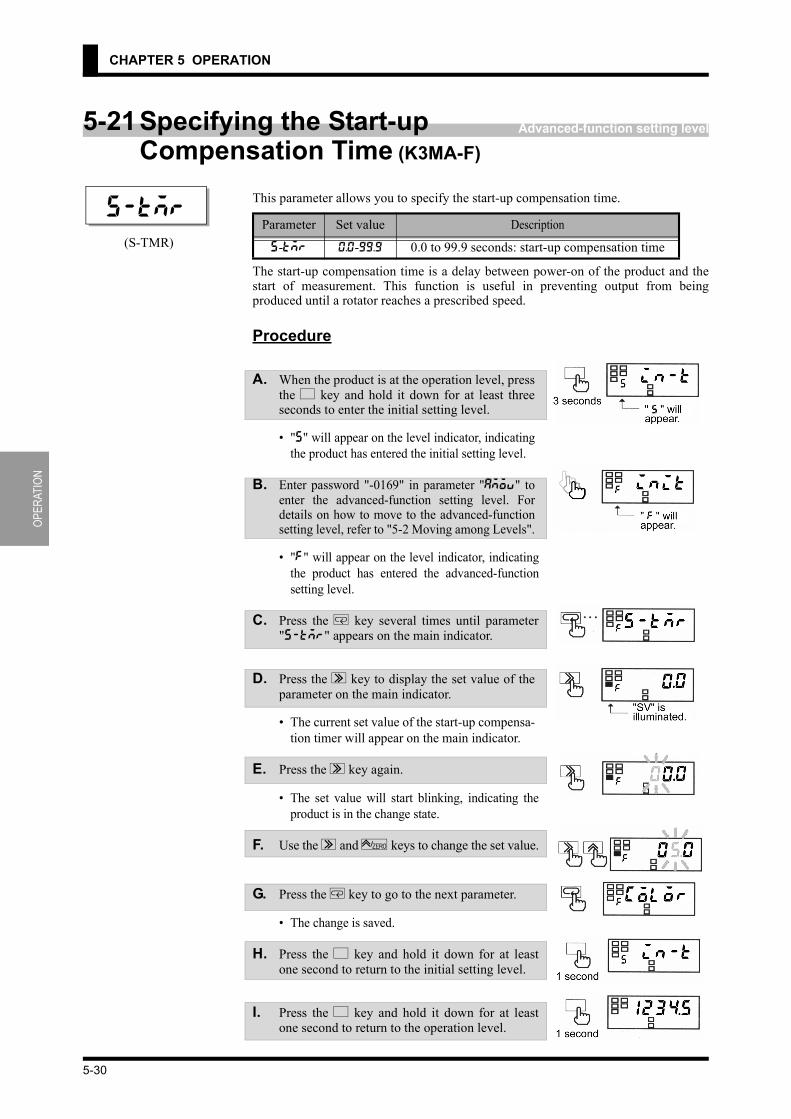
OPER
ATIO
N
CHAPTER 5 OPERATION
Advanced-function setting level5-21Specifying the Start-upCompensation Time (K3MA-F)
This parameter allows you to specify the start-up compensation time.
The start-up compensation time is a delay between power-on of the product and thestart of measurement. This function is useful in preventing output from beingproduced until a rotator reaches a prescribed speed.
Procedure
A. When the product is at the operation level, pressthe L key and hold it down for at least threeseconds to enter the initial setting level.
• "5" will appear on the level indicator, indicatingthe product has entered the initial setting level.
B. Enter password "-0169" in parameter "amov" toenter the advanced-function setting level. Fordetails on how to move to the advanced-functionsetting level, refer to "5-2 Moving among Levels".
• "f" will appear on the level indicator, indicatingthe product has entered the advanced-functionsetting level.
C. Press the M key several times until parameter"s-tmr" appears on the main indicator.
D. Press the S key to display the set value of theparameter on the main indicator.
• The current set value of the start-up compensa-tion timer will appear on the main indicator.
E. Press the S key again.
• The set value will start blinking, indicating theproduct is in the change state.
F. Use the S and U keys to change the set value.
G. Press the M key to go to the next parameter.
• The change is saved.
H. Press the L key and hold it down for at leastone second to return to the initial setting level.
I. Press the L key and hold it down for at leastone second to return to the operation level.
Parameter Set value Description
s-tmr 0.0-99.9 0.0 to 99.9 seconds: start-up compensation time
s-tmr
(S-TMR)
5-30

OPERATION
5-22 Specifying the Zero-limit (K3MA-J)
Advanced-function setting level5-22 Specifying the Zero-limit (K3MA-J)
These parameters allow you to specify the zero-limit.
The zero-limit is a function to process all the readouts lower than the set value as zero.When you select "ON", the values lower than the zero-limit value are alwaysdisplayed as "0".This function is useful when you want to indicate a minus numerical value as zero orindicate the minimum value of input range as zero.
Procedure
A. When the product is at the operation level, pressthe L key and hold it down for at least threeseconds to enter the initial setting level.
• "5" will appear on the level indicator, indicatingthe product has entered the initial setting level.
B. Enter password "-0169" in parameter "amov" toenter the advanced-function setting level. Fordetails on how to move to the advanced-functionsetting level, refer to "5-2 Moving among Levels".
• "f" will appear on the main indicator, indicatingthe product has entered the advanced-functionsetting level.
C. Press the M key several times until parameter"z-lim" appears on the main indicator.
D. Press the S key to display the set value of theparameter on the main indicator.
• The current set value of zero-limit will appear onthe main indicator.
E. Press the S key again.
• The set value will start blinking, indicating theproduct is in the change state.
Parameter Set value Description
z-lim
(Z-LIM)off OFF: Zero-limit function is not available.on ON: Zero-limit function
lim-p 0-99 0 to 99: Zero-limit valuelim-p
z-lim(Z-LIM)
(LIM-P)
5-31

OPER
ATIO
N
CHAPTER 5 OPERATION
F. Use the U key to change the set value.
G. Press the M key to go to the next parameter.
• The change is saved and the next parameter"lim-p" will appear on the main indicator.(When "OFF" is selected, "lim-p" will notappear.)
H. Press the S key to display the set value of theparameter on the main indicator.
• The current set value of zero-limit will appear onthe main indicator.
I. Press the S key again.
• The set value will starts blinking, indicating theproduct is in the change state.
J. Use the S and U keys to change the set value.
K. Press the M key to go to the next parameter.
• The change is saved.
L. Press the L key and hold it down for at leastone second to return to the initial setting level.
M. Press the L key and hold it down for at leastone second to return to the operation level.
5-32

OPERATION
5-23 Changing the Display Color
Advanced-function setting level5-23Changing the Display ColorThis parameter allows you to change the display color of the main indicator.
Procedure
A. When the product is at the operation level, pressthe L key and hold it down for at least threeseconds to enter the initial setting level.
• "5" will appear on the main indicator, indicatingthe product has entered the initial setting level.
B. Enter password "K3MA-J or K3MA-F : -0169,K3MA-L : -169" in parameter "amov" to enterthe advanced-function setting level. For detailson how to move to the advanced-function settinglevel, refer to "5-2 Moving among Levels".
• "f" will appear on the level indicator, indicating theproduct has entered the advanced-function setting level.
C. Press the M key several times until parameter"color" appears on the main indicator.
D. Press the S key to display the set value of theparameter on the main indicator.
• The current set value of changing the displaycolor will appear on the main indicator.
E. Press the S key again.
• The set value will start blinking, indicating theproduct is in the change state.
F. Use the U key to change the set value.
G. Press the M key to go to the next parameter.
• The change is saved.
H. Press the L key and hold it down for at leastone second to return to the initial setting level.
I. Press the L key and hold it down for at leastone second to return to the operation level.
Parameter Set value Description
color
(COLOR)
grn-rGreen-red: The display color is normally green, and
changes to red at comparative output ON.grn Green: The display color is always green.
red-gRed-green: The display color is normally red, and
changes to green at comparative output ON.red Red: The display color is always red.
color(COLOR)
5-33

OPER
ATIO
N
CHAPTER 5 OPERATION
Advanced-function setting level
If the display auto-returnfunction is activated in themiddle of parameter setting,the product saves the currentvalue of the parameter andthen returns to the currentvalue display mode.
5-24Changing the Display Auto-return Time
This parameter allows you to change the display auto-return time.
If no key is operated for a prescribed time, the product returns to the current valuedisplay mode at the operation/adjustment level. This prescribed time is called thedisplay auto-return time.
Procedure
A. When the product is at the operation level, pressthe L key and hold it down for at least threeseconds to enter the initial setting level.
• "5" will appear on the level indicator, indicatingthe product has entered the initial setting level.
B. Enter password "K3MA-J or K3MA-F : -0169,K3MA-L : -169" in parameter "amov" to enterthe advanced-function setting level. For detailson how to move to the advanced-function settinglevel, refer to "5-2 Moving among Levels".
• "f" will appear on the level indicator, indicatingthe product has entered the advanced-functionsetting level.
C. Press the M key several times until parameter"ret" appears on the main indicator.
D. Press the S key to display the set value of theparameter on the main indicator.
• The current set value of the display auto-returntime will appear on the main indicator.
E. Press the S key again.
• The set value will start blinking, indicating theproduct is in the change state.
F. Use the S and U keys to change the set value.
G. Press the M key to go to the next parameter.
• The change is saved.
H. Press the L key and hold it down for at leastone second to return to the initial setting level.
I. Press the L key and hold it down for at leastone second to return to the operation level.
Parameter Set value Description
ret
(RET)0 0 sec: Display auto-return is not available.
1-99 1 to 99 sec: Display auto-return time
ret(RET)
5-34

OPERATION
5-25 Changing the Move-to-Protect-Level Time
Advanced-function setting level
A move-to-protect-level timesetting of "0" is assumed tobe a setting of "1".
5-25Changing the Move-to-Protect-Level Time
This parameter allows you to change the move-to-protect-level time.
Parameter
If you press the L+M keys and hold them down for at least five seconds (aprescribed time), the product enters the protect level. This prescribed time is called themove-to-protect-level time.Depending on the setting of the parameter, the product moves from the operation levelto the protect levels as follows.
Procedure
A. When the product is at the operation level, pressthe L key and hold it down for at least threeseconds to enter the initial setting level.
• "5" will appear on the level indicator, indicatingthe product has entered the initial setting level.
B. Enter password "K3MA-J or K3MA-F : -0169,K3MA-L : -169" in parameter "amov" to enterthe advanced-function setting level. For detailson how to move to the advanced-function settinglevel, refer to "5-2 Moving among Levels".
• "f" will appear on the level indicator, indicatingthe product has entered the advanced-functionsetting level.
C. Press the M key several times until parameter"prlt" appears on the main indicator.
D. Press the S key to display the set value of theparameter on the main indicator.
• The current set value of the move-to-protect-level time will appear on the main indicator.
E. Press the S key again.
• The set value will start blinking, indicating theproduct is in the change state.
Parameter Set value Description
prlt 0-19 0 to 19 sec: Move-to-protect-level time
prlt(PRLT)
5-35

OPER
ATIO
N
CHAPTER 5 OPERATION
F. Use the S and U keys to change the set value.
G. Press the M key to go to the next parameter.
• The change is saved.
H. Press the L key and hold it down for at leastone second to return to the initial setting level.
I. Press the L key and hold it down for at leastone second to return to the operation level.
5-36

6-1
CHAPTER 6
FUNCTIONDESCRIPTION
This chapter describes available functions of the product including measurement andaverage processing.Settings related to comparative outputs can be made only for models that havecomparative outputs (K3MA-J-A2, K3MA-F-A2, and K3MA-L-C).
6-1 Measurement (K3MA-J) ................................................................................6-2Voltage/Current Input/Scaling/Zero-limit/Forced-zero
6-2 Measurement (K3MA-L) ...............................................................................6-5Temperature Input/Temperature Input Correction
6-3 Measurement (K3MA-F) ...............................................................................6-6Pulse Input/Scaling/Auto-zero/Start-up Compensation Timer
6-4 Average Processing ........................................................................................6-10
6-5 Comparative Output .......................................................................................6-11
6-6 Hysteresis .......................................................................................................6-12
6-7 Display Color Change ....................................................................................6-13

FUNC
TION
DE
SCRI
PTIO
NCHAPTER 6 FUNCTION DESCRIPTION
6-1 Measurement (K3MA-J)
Voltage/Current InputK3MA-J operates as a Process meter.Measurements are made as follows.
• Input signals are sampled in synchronization with internal timings generated atintervals of 250 ms.
• The input signal is scaled and the process value is updated according to the scal-ing result. The updated process value is displayed on the main indicator.
• Comparative output is provided based on the process value.• The process value and comparative output are updated per sampling.
ScalingScaling is to convert sampled input values to process values in sequence using apredetermined scaling formula.
Scaling allows conversion of input values to process values in easy-to-understandnotation.
The scaling formula for voltage and current input is as follows.
Where;INP1: Input value corresponding to process value DSP1DSP1: Process value corresponding to input value INP1INP2: Input value corresponding to process value DSP2DSP2: Process value corresponding to input value INP2inp: Input value sampled
6-2

FUNCTION DESCRIPTION
6-1 Measurement (K3MA-J)
dsp: Process value corresponding to inpEnter INP1, DSP1, INP2 and DSP2 to specify the scaling factor.This way of specifying the scaling factor permits flexible scaling; inverse scalingwhere the process value decreases with the increasing input value is also possible.
* For details on how to specify the scaling factor, refer to "5-12 Specifying theScaling Factor (K3MA-J)".
Zero-limitThe zero-limit is a function to display all the readouts lower than a predeterminedvalue as zero.This is useful when you want to display a minus numerical value as zero or display avalue in the vicinity of the minimum of input range as zero.Digits of 00 to 99 can be set.
6-3

FUNC
TION
DE
SCRI
PTIO
NCHAPTER 6 FUNCTION DESCRIPTION
Forced-zeroThis feature shifts a process value to zero forcedly, and can be used to evaluate anddisplay the deviation of a process value from a reference value.The forced-zero function can be activated by using U key on the front panel whena current value is displayed on the main indicator.The following illustrates the forced-zero and forced-zero cancel operation.
• When the U key is pressed, the current process value is shifted to zero forc-edly.
• Thereafter, measurements are made relative to the zero point.• When the U key is pressed while the forced-zero function has been activated,
the current process value is further shifted to zero. • When the U key is pressed and held down for at least one second, the forced-
zero operation is canceled.
Because the forced-zero and forced-zero cancel operation using the U key is storedin the internal nonvolatile storage of the product, the forced-zero state is alive even ifthe power turned off and on again.
6-4

FUNCTION DESCRIPTION
6-2 Measurement (K3MA-L)
6-2 Measurement (K3MA-L)
Temperature InputK3MA-L operates as a Temperature meter.Measurements are made as follows.
• Input signals are sampled in synchronization with internal timings generated atintervals of 500 ms.
• The input signal is scaled according to the sensor type and converted into tem-perature, and the process value is updated. The updated process value is dis-played on the main indicator.
• Comparative output is provided based on the process value.• The process value and comparative output are updated per sampling.
Temperature Input CorrectionThe input temperature is corrected by the quantity of the set value of "temperatureinput correction value" at all points in the whole sensor range.If the correction value is 1.2 °C, the current value of 200 °C before correction will beprocessed as 201.2 °C after correction.
6-5

FUNC
TION
DE
SCRI
PTIO
NCHAPTER 6 FUNCTION DESCRIPTION
6-3 Measurement (K3MA-F)
Pulse InputK3MA-F operates as a Frequency/Rate meter.Measurements are made as follows.
• When the input pulse frequency is 4 Hz or more, it is measured in synchroniza-tion with internal timings generated at intervals of 250 ms.
• The input pulse frequency is scaled and the process value is updated according tothe scaling result.
• Comparative output is provided based on the process value.• The process value and comparative output are updated at intervals of 250 ms.• When the input pulse frequency is less than 4 Hz, it is measured with pulse input
timings.• Therefore, the intervals at which the process value and comparative output are
updated lengthen in accordance with the decreasing input pulse frequency.
Minimum Pulse Width For pulse input, devices of low-speed contact output type or high-speed transistoroutput type can be connected to the terminal depending on parameter setting.
When using a device of low-speed contact output type, set the input pulse frequencyto "30 Hz". To remove chattering noise when the input pulse frequency is "30 Hz",both ON and OFF pulses must have at least 15 ms in width.When using a device of high-speed transistor output type, set the input pulsefrequency to "5 kHz". In this case, both ON and OFF pulses must have at least 90 μsin width.
6-6

FUNCTION DESCRIPTION
6-3 Measurement (K3MA-F)
ScalingScaling is to convert sampled input values to process values in sequence using apredetermined scaling formula.
Scaling allows conversion of input values to process values in easy-to-understandnotation.
The scaling formula for pulse input is as follows.
Where;INP: Input pulse frequency (Hz) corresponding to process value DSPDSP: Process value corresponding to input pulse frequency INPinp: Input pulse frequency (Hz)dsp: Process value corresponding to inpEnter INP and DSP to specify the scaling factor.
6-7

FUNC
TION
DE
SCRI
PTIO
NCHAPTER 6 FUNCTION DESCRIPTION
Conversion of the input pulse frequency to the rotational speed involves the followingscaling formula.
Where;P: Number of pulses per rotationinp: Input pulse frequency (Hz)dsp: Rotational speed (r/min)
Conversion of the input pulse frequency to the circumferential speed involves thefollowing scaling formula.
Where;π: Circular constantP: Number of pulses per rotationR: Diameter of rotor (m)inp: Input pulse frequency (Hz)dsp: Circumferential speed (m/min)
Auto-zeroK3MA-F has an input pulse frequency range of 0.05 to 30 Hz or 0.05 to 5 kHz, andhence the maximum interval between pulses is 20 seconds.This means that the product may provide a lower-limit signal action as late as amaximum of 20 seconds after receiving the last pulse, which results in a poorresponsibility for the lower-limit action.
To eliminate such a situation, K3MA-F has an auto-zero function that shifts theinput pulse frequency to zero forcedly when no pulse is received for a predeterminedtime.This function improves the product responsibility for the lower-limit action.The time between reception of the last impulse and zero-shifting of the input pulsefrequency is called the auto-zero time. The auto-zero time can be specified using the"auto-zero time" parameter. Specify the auto-zero time somewhat longer than theexpected longest interval between input pulses.
Unit conversion (r/s): (r/min)÷60
Unit conversion(m/s): (m/min)÷60(mm/s): (m/min)×1000÷60
6-8

FUNCTION DESCRIPTION
6-3 Measurement (K3MA-F)
Start-up Compensation TimerK3MA-F has a start-up compensation timer that prevents measurement for apredetermined time after power-on.This function is useful in keeping the product in wait state until a rotor reaches thesteady state speed when the product and the rotator have been powered onsimultaneously.The time between power-on of the product and the start of measurement can bespecified using the "start-up compensation time" parameter.
6-9

FUNC
TION
DE
SCRI
PTIO
NCHAPTER 6 FUNCTION DESCRIPTION
6-4 Average ProcessingThis function averages a specified number of measurements.It is useful for preventing readout from fluctuating due to unstable input such as spikenoise.
The average processing of the K3MA provides a simple average (an arithmetic mean).The number of measurements for averaging that can be specified is as follows.- No average processing (the number of measurements for averaging: 1)- 2- 4- 8The number of measurements for averaging is the number of times the process valueis updated as described in "Measurement".The following shows the relationship between the number of measurements foraveraging and the interval at which the process value and comparative output areupdated.
Number of measurements for averaging
Update interval
K3MA-J K3MA-LK3MA-F
Input pulse4 Hz and more
Input pulseLess than 4 Hz
No average processing 250 ms 500 ms 250 ms Every input pulse
2 500 ms 1 second 500 ms Every 2 input pulses
4 1 second 2 seconds 1 second Every 4 input pulses
8 2 seconds 4 seconds 2 seconds Every 8 input pulses
6-10

FUNCTION DESCRIPTION
6-5 Comparative Output
Upper-limit Action
Lower-limit Action
Outside-the-range Action
6-5 Comparative OutputComparative outputs 1 and 2 can be produced as three types of signal actions: upper-limit signal action, lower-limit signal action, and outside-the-range signal action.
Comparative output turns onwhen the process valuereaches the OUT set value.Comparative output turns offwhen the process valuedecreases to (OUT set value -hysteresis).
Comparative output turns onwhen the process valuedecreases to the OUT setvalue.Comparative output turns offwhen the process valuereaches (OUT set value +hysteresis).
Comparative output turns onwhen the process valuereaches the OUT upper-limitvalue or decreases to the OUTlower-limit value.Comparative output turns offwhen the process value fallsinside the range of (OUTupper-limit value - hysteresis)to (OUT lower limit value +hysteresis).
Combinations of comparative output 1 and 2 offer the possibility of producing a widevariety of actions including upper-limit + another upper-limit actions, lower-limit +another lower-limit actions, and two-level outside-the-range actions.
6-11

FUNC
TION
DE
SCRI
PTIO
NCHAPTER 6 FUNCTION DESCRIPTION
6-6 HysteresisIn this manual, hysteresis refers to a range that is provided above or below an OUTset value to avoid comparative output from turning off unless the process value fallsoutside the range, once the comparative output has turned on at the OUT set value. Specifying the hysteresis suppresses chattering of comparative output caused byfluctuations of the process value in the vicinity of OUT set value.
Comparative output ON/OFF conditions are as follows.Upper-limit action
ON: Process value ≥ OUT set valueOFF: Process value ≤ OUT set value - Hysteresis
Lower-limit actionON: Process value ≤ OUT set valueOFF: Process value ≥ OUT set value + Hysteresis
Hysteresis can be set to a desired value using parameter "hysteresis".
6-12

FUNCTION DESCRIPTION
6-7 Display Color Change
6-7 Display Color ChangeThe display color of the main indicator can be changed.This feature can be used to vary the display color of the gang-mounted productsdepending on their importance or to greater prominence to indication on the mainindicator of certain products in an emergency.
Four display color change options are available.Green to red: The display color of the main indicator is green when both of
comparative outputs 1 and 2 are off, and changes to red when eitherof the comparative outputs turns on.
Always green: The display color is always green.Always red: The display color is always red.Red to green: The display color is red when both of comparative outputs 1 and 2
are off, and changes to green when either of comparative outputsturns on.
6-13


7-1
CHAPTER 7
TROUBLESHOOTINGGUIDE
This chapter describes malfunctions and troubles of the product, and how to deal withthese problems.
7-1 Indication of Error ..........................................................................................7-2
7-2 Troubleshooting Table ....................................................................................7-3

TROU
BLES
HOOT
ING
GUID
ECHAPTER 7 TROUBLESHOOTING GUIDE
7-1 Indication of Error
Level indicator
Main indicator Error description Remedy
Off e111Internal storage is out of order. Repair of the product is necessary.
Contact a branch office of the company.
s e111Nonvolatile storage is out of order. Repair of the product is necessary.
Contact a branch office of the company.
Off s.err blinking
The current range of 4 to 20 mA is selected for K3MA-J in the factory. Therefore, when the product is powered on for the first time after installation, and if nothing is connected to the current input terminals, this state will occur because of the input of 0 mA.
At the initial setting level, specify an appropriate input type in accordance with the application.
Input is abnormal. (K3MA-J)Supply voltage/current inputs that fall within the measuring range.The measuring range of each input type is as follows.
0-20 mA range: -2-22 mA4-20 mA range: 2-22 mA0-5 V range: -0.5-5.5 V1-5 V range: 0.5-5.5 V±5 V range: -5.5-5.5 V±10 V range: -11-11 V
If the product does not return to normal, repair of the product is necessary.Contact a branch office of the company.(K3MA-L)Check the incorrect wiring, disconnection, and short of the input, and input type.Input value is outside the display range (control range). Quickly return the input value to within the display range.If the product does not return to normal, repair of the product is necessary.Contact a branch office of the company.
Off 99999 blinking
The scaled process value is higher than 99999.
(For K3MA-L: 9999)
Supply input values that fall within allowable range.The scaling factor may be inappropriate. Review the scaling factor again at the initial setting level.
Off :9999
blinking
The scaled process value is less than -19999.
(For K3MA-L: -1999)
Supply input values that fall within allowable range.The scaling factor may be inappropriate. At the initial setting level, review the scaling factor again.
7-2

TROUBLESHOOTING GUIDE
7-2 Troubleshooting Table
7-2 Troubleshooting Table
Symptom Item to be checked Remedy Reference page
The forced-zero function is inoperative even though the U key is pressed.
Check if the forced-zero lockout is active.
At the protect level, set the forced-zero lockout to "Enable".
5-12
The product does not enter the protect level even though the L+M keys are held down for five seconds.
Check the specified value of parameter "move-to-protect-level time".
The time required for moving to the protect level can be changed by this parameter. Set it to an appropriate value.
5-35
Readouts vary greatly or decreases with increasing rota-tional speed. (K3MA-F)
Check if the set value of parameter "input-pulse frequency" is "30 Hz"?
When the input pulse is higher than 30 Hz, set the set value of this parameter to "5 kHz".
5-16
Check if the pulse frequency of input pulse is higher than 5 kHz.
Return the input pulse frequency to within measuring range.Note that K3MA does not generate an "outside-of-measuring-range" error even if the input pulse frequency exceeds 5 kHz.
Readouts vary or are incorrect even when the rotational speed is low.(K3MA-F)
Check if the pulse width of ON/OFF signals meets the specification.
The product can not recognize input pulses correctly unless their width is as specified, even if the rotational speed is low. Supply the product with pulses that have a width specified in this manual.
6-6
The main indicator reads "0" when the rotational speed is low.(K3MA-F)
Check if the set value of parameter "auto-zero time" is larger than the maximum time interval of input pulses.
Set this parameter to a larger value than the maximum time interval of input pulses.Otherwise, auto-zero functions to shift the readout to zero.
5-28
6-6
The product continues to read "00000" on the main indicator since powered on.(K3MA-F)
Check if the set value of parameter "startup compensation time" is too long.
Set the set value of this parameter to an appropriate value.In K3MA-J, the startup compensation time can be set to up to 99 seconds.
5-30
6-9
Comparative output does not turn off even when a process value goes back to normal.
Check if the set value of parameter "hysteresis" is too large.
Set this set value to an appropriate value.
5-27
6-12
7-3


A-1
APPENDIX
Specifications ..................................................................................................A-2
Parameter List .................................................................................................A-5

APPE
NDIX
APPENDIX
SpecificationsRatings
*[J]:K3MA-J, [L]:K3MA-L, [F]:K3MA-F
Reley Contact Output(A2 Type)
(C Type)
Supply voltage 100 to 240VAC(50/60Hz), 24VAC(50/60Hz)/DCOperating voltage range 85% to 110% of the rated supply voltage
Power consumption100 to 240VAC: 6 VA max.24VAC/DC: 4.5 VA/W max. (at max. Load)
Insulation resistance 20 MΩ min. (with 500 V megger) Between all the external terminals and the caseInsulation provided between inputs, outputs, and power supply.
Dielectric withstand voltage 2000VAC 1min Between all the external terminals and the caseInsulation provided between inputs, outputs, and power supply.
Noise immunity±1,500 V on AC power supply terminals in normal or common mode, ±480 V on AC/DC power supply terminals in normal or common mode,±1 μs, or 100 ns for square-wave noise with 1 ns
Vibration resistance Frequency: 10 to 55 Hz Acceleration: 50 m/s2 X,Y,Z direction 5 min×10 sweepsShock resistance 150 m/s2 (Relay contact: 100 m/s2) 3 axes 6 directions × 3 times Input impedance (Typ) Voltage range : 1 MΩ min. Current range : 45 Ω max.Input absolute maximum rating
±30 mA (4 to 20 mA, 0 to 20 mA)±13.5 V (1 to 5 V, 0 to 5 V, ±5 V) ±26 V (±10 V)
Ambient temperature -10 to +55°C (with no condensation or icing)Ambient humidity 25 to 85%Storage temperature -25 to 65°C (with no condensation or icing)Altitude 2,000 m max.Weight Approximately 200g *[J/L] / 220g *[F] (main body)
Item Resistive load(cosφ=1) Inductive load(cosφ=0.4, L/R=7ms)Rated load 250VAC 5A, 30VDC 5A 250VAC 1A, 30VDC 1ARated carry current 5A max. (at COM terminal)Max. contact voltage 250VAC, 150VDCMax. contact current 5A max. (at COM terminal)Max. switching capacity 1250VA, 150W 250VA, 30WMin. permissible load 5VDC, 10mAMechanical life 5,000,000 times min. (at a switching frequency of 1,200 times/min)Electrical life(at an ambient temperature of 20°C) 100,000 times min. (at a rated load switching frequency of 10 times/min)
Item Resistive load(cosφ=1) Inductive load(cosφ=0.4, L/R=7ms)Rated load 250VAC 5A, 30VDC 5A 250VAC 1.5A, 30VDC 1.5ARated carry current 5A max. (at COM terminal)Max. contact voltage 400VAC, 150VDCMax. contact current 5A max. (at COM terminal)Max. switching capacity 2000VA, 192W 375VA, 45WMin. permissible load 5VDC, 10mAMechanical life 20,000,000 times min. (at a switching frequency of 1,200 times/min)Electrical life(at an ambient temperature of 20°C) 100,000 times min. (at a rated load switching frequency of 10 times/min)
A-2

APPENDIX
APPENDIX
Characteristics
*[J]:K3MA-J, [L]:K3MA-L, [F]:K3MA-F
A/D conversion method Double integral methodSampling period 250 ms *[J], 500 ms *[L]Max. displayd digits -19999 to 99999 *[J/F] / -1999 to 9999 *[L]Average processing Simple average of None/2/4/8 measurementsComparative output 1a × 2 *[J/F] / 1c *[L] (Relay contact output)Delay in comparative output 750ms max. *[J/F] / 1s max. *[L]
Other functions
Display color changeKey protectStartup compensation timer (Only K3MA)Auto-zero (Only K3MA)Switching of comparative outputs
Enclosure ratingsFront side: NEMA4X(equivalent to IP66) Rear case: IP20Terminal area: IP00+Finger Protection(VDE106/part100) when the terminal cover is mounted.
Memory protection EEPROM (Nonvolatile storage) Saving times: one hundred thousand times
Ambient atmosphere Installation categoryII, Degree of contamination : 2 (according to IEC61010-1)
Approved standards
UL3121,CSA C22.2 No.14EN61010-1(IEC61010-1):”pollution degree 2,overvoltage category II“EN61326+A1 Industrial use “Class A” (EMI) Emission Enclosure: CISPR11 Group1 Class A:CISPR16-1/-2 Emission AC Mains: CISPR11 Group1 Class A:CISPR16-1/-2 (EMS) Immunity ESD: EN61000-4-2: 4-kV contact discharge
8-kV air discharge Immunity-RF-interference: EN61000-4-3: 10 V/m(amplitude modulated, 80MHz
to 1GHz) Immunity Burst: EN61000-4-4: 2-kV power line
1-kV I/O signal-line Immunity Surge: EN61000-4-5: 1kV (L-N/AC Lines)
2kV(L-PE,N-PE/AC Lines) Immunity Conducted Disturbance: EN61000-4-6: 3 V(0.15 to 80 MHz) Immunity Voltage interrupts: EN61000-4-11:0.5Cycle,0°,180°,100%(rated voltage)
A-3

APPE
NDIX
APPENDIX
Input Characteristics
K3MA-J
K3MA-L
K3MA-F
Input type Setting range Control range Measuring accuracy0-20 0 to 20mA -2 to 22mA
±0.1%FS±1digit max. at 23°C±3°C4-20 4 to 20mA 2 to 22mA0-5 0 to 5V -0.5 to 5,5V1-5 1 to 5V 0.5 to 5.5V5 ±5V ±5.5V
±0.1%FS±1digit max. at 23°C±5°C10 ±10V ±11V
Input type Set value Setting range Control range Indication accuracy
Platinum resistance thermometer
Pt100
0 -200 to 850°C-300 to 1500°F
-220 to 870°C-340 to 1540°F
±0.5% of indicated value or ±1°C, whichever is larger ±1digit max.
1 -199.9 to 500.0°C-199.9 to 900.0°F
-199.9 to 520.0°C-199.9 to 940.0°F
2 0.0 to 100.0°C0.0 to 210.0°F
-20.0 to 120.0°C-40.0 to 250.0°F
JPt1003 -199.9 to 500.0°C
-199.9 to 900.0°F-199.9 to 520.0°C-199.9 to 940.0°F
4 0.0 to 100.0°C0.0 to 210.0°F
-20.0 to 120.0°C-40.0 to 250.0°F
Thermocouple
K5 -200 to 1300°C
-300 to 2300°F-220 to 1320°C-340 to 2340°F
±0.5% of indicated value or ±1°C, whichever is larger ±1digit max.(at a temperature of -100°C or less: ±2°C±1digit max.)
6 -20.0 to 500.0°C0.0 to 900.0°F
-40.0 to 520.0°C-40.0 to 940.0°F
±0.5% of indicated value or ±1°C, whichever is larger ±1digit max.J
7 -100 to 850°C-100 to 1500°F
-120 to 870°C-140 to 1540°F
8 -20.0 to 400.0°C0.0 to 750.0°F
-40.0 to 420.0°C-40.0 to 790.0°F
T9 -200 to 400°C
-300 to 700°F-220 to 420°C-340 to 740°F ±0.5% of indicated value or ±1°C, whichever is larger
±1digit max.(at a temperature of -100°C or less: ±2°C±1digit max.)10 -199.9 to 400.0°C
-199.9 to 700.0°F-199.9 to 420.0°C-199.9 to 740.0°F
E 11 0 to 600°C0 to 1100°F
-20 to 620°C-40 to 1140°F
±0.5% of indicated value or ±1°C, whichever is larger ±1digit max.
L 12 -100 to 850°C-100 to 1500°F
-120 to 870°C-140 to 1540°F
±2°C±1digit max.U
13 -200 to 400°C-300 to 700°F
-220 to 420°C-340 to 740°F
14 -199.9 to 400.0°C-199.9 to 700.0°F
-199.9 to 420.0°C-199.9 to 740.0°F
N 15 -200 to 1300°C-300 to 2300°F
-220 to 1320°C-340 to 2340°F
±0.5% of indicated value or ±1°C, whichever is larger ±1digit max.(at a temperature of -100°C or less: ±2°C±1digit max.)
R 16 0 to 1700°C0 to 3000°F
-20 to 1720°C-40 to 3040°F ±0.5% of indicated value or ±1°C, whichever is larger
±1digit max.(at a temperature of 200°C or less: ±3°C±1digit max.)S 17 0 to 1700°C
0 to 3000°F-20 to 1720°C-40 to 3040°F
B 18 100 to 1800°C300 to 3200°F
0 to 1820°C0 to 3240°F
±0.5% of indicated value or ±1°C, whichever is larger ±1digit max.(at a temperature of 400°C or less is unrestricted.)
Pulse frequency Setting range Measuring accuracy30 0.05 to 30Hz (Minimum pulse width: 15ms)
±0.1%FS±1digit max. at 23°C±5°C5k 0.05 to 5kHz (Minimum pulse width: 90μs)
A-4

APPENDIX
APPENDIX
Parameter ListUse this list to note your set values.
K3MA-J
Level Parameter Indication Setting range Default Unit Set value
Protect
Operation/adjustment lockouts oapt 0-2 0
Setting level lockout icpt 0-2 1
Setting change lockout wtpt off/on off
Forced-zero lockout zrpt off/on on
Operation
OUT1 Value out1 :9999-99999 99999
OUT1 upper-limit value out!h :9999-99999 99999
OUT1 lower-limit value out!l :9999-99999 :9999
OUT2 value out2 :9999-99999 :9999
OUT2 upper-limit value outBh :9999-99999 99999
OUT2 lower-limit value outBl :9999-99999 :9999
Initial setting
Input type in-t 0-20/4-20/0-5/1-5/5/10
4-20
Scaling input value 1 inp.1 :9999-99999 4.00
Scaling display value 1 dsp.1 :9999-99999 400
Scaling input value 2 inp.2 :9999-99999 20.00
Scaling display value 2 dsp.2 :9999-99999 2000
Decimal point positiondp ,.,,,,/,,.,,,/
,,,.,,/,,,,.,/,,,,,
,,,.,,
OUT1 type out1.t hi/lo/hi-lo hi
OUT2 type out2.t hi/lo/hi-lo lo
Move to advanced-function set-ting level
amov :9999-99999 0
Advanced-function setting
Parameter initialization init off/on off
No. of measurements for averaging
avg off/2/4/8 off time
OUT1 hysteresis hys1 0-9999 1
OUT2 hysteresis hys2 0-9999 1
Zero-limit z-lim off/on off
Zero-limit value lim-p 0-99 0
Display color change color grn-r/grn/red-g/red
grn-r
Display auto-return time ret 0-99 10 sMove-to-protect-level time prlt 0-19 5 s
A-5

APPE
NDIX
APPENDIX
K3MA-L
Level Parameter Indication Setting range Default Unit Set value
Protect
Operation/adjustment lockouts oapt 0-2 0
Setting level lockout icpt 0-2 1
Setting change lockout wtpt off/on off
OperationOUT1 value out1 :999-9999 9999
OUT1 upper-limit value out!h :999-9999 9999
OUT1 lower-limit value out!l :999-9999 :999
Adjustment Temperature input correc-tion value ins :999-9999 0
Initial setting
Input type in-t
0: Pt1001: Pt1002: Pt1003: JPt1004: JPt100
5
5: K6: K7: J8: J9: T10: T11: E12: L13: U14: U15: N16: R17: S18: B
Temperature unit d-u c/f c
OUT1 type out1.t hi/lo/hi-lo hi
Move to advanced-func-tion setting level amov :999-9999 0
Advanced-function set-
ting
Parameter initialization init off/on off
No. of measurements for averaging avg off/2/4/8 off time
OUT1 hysteresis hys1 0-9999 1
Display color change colorgrn-r/grn/red-g/
redgrn-r
Display auto-return time ret 0-99 10 sMove-to-protect-level
time prlt 0-19 5 s
Res
ista
nce
ther
mom
eter
Ther
moc
oupl
e
A-6

APPENDIX
APPENDIX
K3MA-F
Level Parameter Indication Setting range Default Unit Set value
ProtectOperation/adjustment lockouts oapt 0-2 0
Setting level lockout icpt 0-2 1
Setting change lockout wtpt off/on off
Operation
OUT1 Value out1 :9999-99999 99999
OUT1 upper-limit value out!h :9999-99999 99999
OUT1 lower-limit value out!l :9999-99999 :9999
OUT2 value out2 :9999-99999 :9999
OUT2 upper-limit value outBh :9999-99999 99999
OUT2 lower-limit value outBl :9999-99999 :9999
Initial setting
Pulse frequency p-fre 30/5k 5k HzScaling input value inp 0-99999 5000
Scaling display value dsp :9999-99999 5000
Decimal point positiondp ,.,,,,/,,.,,,/
,,,.,,/,,,,.,/,,,,,
,,,,,
OUT1 type out1.t hi/lo/hi-lo hi
OUT2 type out2.t hi/lo/hi-lo lo
Move to advanced-function set-ting level
amov :9999-99999 0
Advanced-function setting
Parameter initialization init off/on off
No. of measurements for averaging
avg off/2/4/8 off time
OUT1 hysteresis hys1 0-9999 1
OUT2 hysteresis hys2 0-9999 1
Auto-zero time auto.z 0.0-19.9 19.9 sStartup compensation timer s-tmr 0.0-99.9 0.0 s
Display color change color grn-r/grn/red-g/red
grn-r
Display auto-return time ret 0-99 10 sMove-to-protect-level time prlt 0-19 5 s
A-7

INDEX
Aabsolute maximum rating........................................ 2-6adapter..................................................................... 2-2adjustment ............................................................... 5-2adjustment level ...................................................... 5-3advanced-function setting ....................................... 5-2advanced-function setting level .............................. 5-4alphabets ................................................................. 5-6analog input............................................................. 1-5auto-zero ......................................................... 6-8,5-28auto-zero time ....................................................... 5-28average processing ................................................ 6-10
C
change state ............................................................. 5-6comparative output....................................1-3,2-5,6-11contact output.......................................................... 1-6crimp contact type terminals................................... 2-5current leakage with transistor turned ON.............. 2-6
D
decimal point position........................................... 5-22digital panel meter................................................... 1-2dimensions .............................................................. 2-2display auto-return time ........................................ 5-34display color.................................................... 1-3,5-33display color change ............................................. 6-13
F
forced-zero ........................................................ 5-9,6-4forced-zero lockout ............................................... 5-12
H
hysteresis....................................................... 5-27,6-12hysteresis (width) .................................................. 6-12
I
I/O circuit ................................................................ 1-5I/O terminal connections......................................... 2-4Indication of error ................................................... 7-2
initial setting...................................................... 4-1,5-2initial setting level ................................................... 5-3initialize all parameters ......................................... 5-25input circuit diagrams.............................................. 1-5input range over ...................................................... 4-2input type............................................................... 5-14installation............................................................... 2-2installation procedure .............................................. 2-3internal block diagram ............................................ 1-6internal nonvolatile storage ..................................... 6-4
K
key protect............................................................. 5-12
L
level ......................................................................... 5-2load.......................................................................... 2-5lower-limit signal action ............ 3-3,3-5,3-9,3-11,6-11
M
main features ........................................................... 1-2measurement ........................................................... 6-2min. load current ..................................................... 2-6model number legend.............................................. 1-4monitor state............................................................ 5-6move-to-protect-level time.................................... 5-35
N
number of measurements for averaging........ 5-26,6-10numerics .................................................................. 5-6
O
OFF leakage current................................................ 2-6OFF pulse width...................................................... 6-6ON pulse width ....................................................... 6-6ON residual voltage ................................................ 2-6operation.................................................................. 5-2operation/adjustment lockouts .............................. 5-12OUT1 lower-limit value .......................................... 5-8OUT1 upper-limit value .......................................... 5-8

OUT1 value............................................................. 5-8OUT2 lower-limit value.......................................... 5-8OUT2 upper-limit value.......................................... 5-8OUT2 value............................................................. 5-8output circuit diagrams ........................................... 1-6outside-the-range signal action ....................... 3-7,6-11
P
panel cutout dimensions.......................................... 2-2parameter................................................................. 5-5password ................................................................. 5-4power supply........................................................... 2-5pressure sensor ........................................................ 3-4protect ..................................................................... 5-2protect level............................................................. 5-3proximity switch ..................................................... 3-8pulse frequency ..................................................... 5-16pulse input ...................................................1-5,2-6,6-6
R
remove chattering.................................................... 6-6
S
sampling............................................................ 6-2,6-5scaling .........................................................1-2,6-2,6-7scaling factor................................................. 5-17,5-19scaling formula.................................................. 6-2,6-7scaling operation error .......................................... 5-21
selecting a comparative output.............................. 5-24set values ................................................................. 5-6setting change lockout........................................... 5-12setting level lockout .............................................. 5-12shift.......................................................................... 1-3spike noise............................................................. 6-10start-up compensation time ................................... 5-30start-up compensation timer.................................... 6-9supply capacity........................................................ 2-5suppresses chattering............................................. 6-12
T
teaching function........................................... 5-18,5-20terminal arrangement .............................................. 2-4terminal connection................................................. 2-5
U
ultrasonic displacement sensor................................ 3-2upper-limit signal action ...... 3-3,3-5,3-7,3-9,3-11,6-11
V
viewing and changing the OUT set values.............. 5-7
W
waterproof ............................................................... 2-3watertight packing................................................... 2-3

N106-E
1-04K
3MA
Series D
igital P
anel M
etersU
ser’ s Man
ual


Authorized Distributor:
In the interest of product improvement, specifications are subject to change without notice.
Cat. No. N106-E1-04 0117
© OMRON Corporation 2001-2017 All Rights Reserved.
OMRON Corporation Industrial Automation Company
OMRON ELECTRONICS LLC2895 Greenspoint Parkway, Suite 200 Hoffman Estates, IL 60169 U.S.A.Tel: (1) 847-843-7900/Fax: (1) 847-843-7787
Regional HeadquartersOMRON EUROPE B.V.Wegalaan 67-69, 2132 JD HoofddorpThe NetherlandsTel: (31)2356-81-300/Fax: (31)2356-81-388
Contact: www.ia.omron.comKyoto, JAPAN
OMRON ASIA PACIFIC PTE. LTD.No. 438A Alexandra Road # 05-05/08 (Lobby 2), Alexandra Technopark, Singapore 119967Tel: (65) 6835-3011/Fax: (65) 6835-2711
OMRON (CHINA) CO., LTD.Room 2211, Bank of China Tower, 200 Yin Cheng Zhong Road, PuDong New Area, Shanghai, 200120, ChinaTel: (86) 21-5037-2222/Fax: (86) 21-5037-2200