digital power meter wt1600 - electro-meters wt1600 is a power meter designed for measurement of ......
TRANSCRIPT

Bulletin 7601-00E
WT 1600Digital Power Meter
Frequency Range DC, 0.5 Hz to 1 MHz
Basic Accuracy: ±0.1%
Up to Six Input Elements in one Instrument
Current Input Range: 10 mA to 5 A or 1 A to 50 A
Voltage Input Range: 1.5 V to 1000 V
3 phase power input from two systems in one unit 50 ms data storing interval A variety of display formats
Standard integration and harmonic measurement functions Standard external current sensor input for use with current clamps
TotalSolution
Numerical, Waveform, and Trend Displays
www.yokogawa.com/tm/... and subscribe to “Newswave,”our free e-mail newsletter

2
The WT1600 is a power meter designed for measurement of extremely small currents in energy-savingequipment, as well as measurement of large currents for evaluating large-sized loads. The WT1600 workswith voltages ranging from 1.5 V up to 1000 V, supporting a wide range of applications. Because it canaccept signal inputs for up to six phases, a single WT1600 unit can measure I/O signals on inverters.
Superior Performance
High Precision and Wide BandwidthBasic accuracy: 0.1%Frequency range: DC, 0.5 Hz to 1 MHz
Up to Six-Phase Input on One Unit. SynchronizedMeasurements Between Two UnitsA single WT1600 unit can make up to six different powermeasurements (six inputs each for voltage and current). Withthe measure s tar t -s top funct ion (synchronizedmeasurement), two WT1600 units (12 inputs) can besynchronized.
Data Storing as Fast as 50ms (20 Timesper Second)The data can be stored at intervals as short as 50ms. TheWT1600 rapidly calculates input parameters such as voltagerms, current rms, and power. Measurements can be storedin a 11-MB internal memory, which is helpful for applicationssuch as:• Evaluation of characteristics at motor startup including torque and
rpms (requires the optional motor evaluation function)• Measurement of rapidly fluctuating secondary voltage and lamp
current when a light is turned on
Trend DisplayThe WT1600 displays measurements for each displayupdating interval in a time series. The time axis (T/div) canbe set in the range of 3 seconds to 24 hours (wave off).Changes in up to 16 different parameters, such as voltage,current, active power, and apparent power, can be observedsimultaneously in long-term continuous tests.
Wide Current Input RangesThe WT1600 has two different input elements. A 5 A inputelement is provided for measuring extremely small currents,while a 50 A input element serves to measure large currents.Both of the elements can be installed together in the WT1600.The current for the 5 A input element can be set as low as 10mA for measuring extremely small currents in energy-savingequipment.
Two input elements 5 A input element 10/20/50/100/200/500 mA, 1/2/5 A (DC, 0.5 Hz to 1 MHz) 50 A input element 1/2/5/10/20/50 A (DC, 0.5 Hz to 100 kHz)
Current sensor input range (same for 5 A and 50 A inputelements; standard)50/100/250/500 mV, 1/2.5/5/10 V (DC, 0.5 Hz to 500 kHz)
Wide Voltage Range1.5/3/6/10/15/30/60/100/150/300/600/1000 V
(DC, 0.5 Hz to 1 MHz)
Display Harmonic Data as Bar Graphs,Vectors, and ListsThe harmonic measurement function is a standard featureon the WT1600. It is capable of measuring waveforms with afundamental frequency ranging from 10 Hz to 1 kHz. Analysisresults up to the 100th order from 50/60 Hz fundamental wavescan be displayed asnumerical values orbar graphs. TheW T 1 6 0 0 c a ndisplay harmonicm e a s u r e m e n tresults as lists, andfundamental wavesas vectors.
A Variety of Display FormatsIn addition to numerical data, theWT1600 can display input signalwaveforms. Eleven differentdisplay formats can be selectedon a single WT1600 unit, so it isnot necessary to connect anexternal waveform viewer tocheck waveforms.
Measure start-stop
Integration can be started and stopped element by elementthrough communication between the two units. This enableshighly efficient measurement on manufacturing lines forproducts such as home appliances.
A High-Precision, Wideband Digital Power Meter
Use separate input elements for measurements ranging from large currents down theto very small currents that occur during standby operation
Superior Functions

3
6.4-Inch TFT Color LCDCapable of displaying an easy-to-view four-parameterdisplay (two parameters during simultaneous displaywith waveforms), or increasing the number ofparameters up to 78.
Rotary KnobCan be used in combination with keys next to thescreen for easy operation. The rotary knob allows theuser to rapidly locate the desired parameter fromnumerous parameters shown on the screen.
Saving Waveforms, Numerical Values,and ScreenshotsWaveforms, numerical values, and screenshots canbe saved to the 3.5-inch floppy drive (standard feature)or the optional internal hard drive. Settings can besaved and retrieved.
Optional Features forMore-Efficient Measurements
Ethernet Port (10BASE-T) and Internal HardDriveThe Ethernet function allow you to use FTP server, FTP client,Network printing, Automatic Mail Transfer (SMTP), and others.
D/A Output (30 channels)Analog outputs are available for up to 30 measurementparameters. With the 6-element WT1600, as many as fiveanalog outputs are available for each element.
Motor EvaluationThe WT1600 can measure the output from a speed and torquesensor on the output of an electric motor, and calculate torque,rotating speed, mechanical power, synchronous speed, slip,motor efficiency, and total efficiency. Both analog and pulseinputs can be accepted from the sensor. In addition tonumerical values, waveforms can be displayed to provide avisual picture of fluctuations in parameter values.
Built-In Printer SCSI Interface
Standard Features GP-IB or RS-232 VGA Output
For large-screen display.
Measure Start-Stop FunctionEnables synchronized measurement betweentwo WT1600 units.
External Clock InputEnables accurate measurement of harmonicswhen using low-frequency signal inputs.
VGA output display
Example application for inverter I/O measurement
Trend display of torque and rpms(requires optional motor evaluationfunction)* The screen data shown here is a screenshot.
Input signal example
Output signal example
Inverter Motor Load
Torque meter
A Full Range of Features and Options /Example Applications

4
For more information on WT1600 features and a description of the functions, go to
http://www.yokogawa.com/tm/Bu/WT1600/
Increased Assured-Accuracy Range for High-Precision MeasurementsThe blue bars in the graph below represent the input ranges whereaccuracy is assured relative to range-value ratings. Accuracy forAC voltage and current is assured between 1% and 110%. Forexample, if a 1 A range-value is used, accuracy is assured downto 10 mA.
Instantaneous power as determined through digital sampling
w(t)=v(t)·i(t)
Time
Approximately 5µs
Instantaneous power
0% 50% 100%
0%
0% 110%
50% 100%
1% 110%AC input
DC input
Integration Function Capable of HandlingRapid Changes in Input SignalInput signals are sampled at high speed (approximately 200kHz), so power can be measured even on rapidly fluctuatinginput signals. Integrated power can also be determinedseparately for each polarity.
Basic performance (typical values)Example of frequency versus power accuracy characteristic Power factor error with respect to the reading value for an
arbitrary power factor
Example of frequency characteristics(phase and zero power factor)
Effect of common mode voltage on reading value
Typical value 150V/1A on a 5A input element
Typical value (5A input element) : 0.12%@100kHzTypical value (50A input element): -0.10%@20kHz
Typical value 0.045% (cos∅ = 1)Typical value 0.43% (cos∅ = 0.1)
Frequency (Hz) Power factor
Frequency (Hz)
10 100 1,000 10,000 100,000 1,000,000
Err
or (
% o
f ran
ge)
Err
or (
% o
f rea
ding
)
40.0
30.0
20.0
10.0
0.0
-10.0
-20.0
-30.0
-40.0
Specification for power at cos ∅ = 1
50A input 5A input
Typical value 150V/10A on a 50A input element
0.01%
0.10%
1.00%
10.00%
100.00%
0.01 0.1 1
WT1600
WT200 series
WT2000
WT1600 Typical value
Frequency (Hz)
Err
or (
% o
f ran
ge)
Err
or(%
of r
ange
)
-10.00
-5.00
0.00
5.00
10.00
10 100 1,000 10,000 100,000
Error power factor 150V/10A(50A input element)
-2
0
2
4
6
8
10
1 10 100 1,000 10,000 100,000 1,000,000
1A range on a50A input element
1A range on a5A input element
100V range 15V range
Effective input range relative to range-value rating

5
Specifications
Parameter Input type
Rated value (range-value)
Instrument loss (input resistance)
Instantaneous maximum allowed input (1 cycle, for 20 ms)
Continuous maximum allowed input
Continuous maximum in-phase voltage (50/60 Hz)Common mode rejection ratio(600 Vrms)Input terminal type
A/D converter Switching range-value Auto-range function
VoltageFloating inputResistive potential division method1.5/3/6/10/15/30/60/100/150/300/600/1000V
Approximately 2MΩ
Peak voltage of 4 kV or rms of 1.5 kV (whichever is lower)
Peak voltage of 1.5 kV or rms of 1 kV (whichever is lower)
600 Vrms CATII
(with voltage input terminals shorted and current input terminals open) 50/60 Hz: ±0.01% of rng or less (±(0.01 × 15/(rated value of rng))% of rng or less for 10-V rng or less).Up to 100 kHz: Reference value ±(0.1 × f% of rng) or less, (±(0.1 × f × 15/(rated value of rng))% of rng or less for 10-V rng or less), but no less than 0.01% ; frequency unit: kHzPlug-in terminal (safety terminal)
Voltage/current input simultaneous conversion, 16-bit resolution, conversion speed of approximately 5 µsecRange-value can be set independently for each element, through manual setting, automatic setting, or online setting Increasing range-value: Range-value is increased when rms exceeds 110% of rated value or peak value exceeds approximately 330% of rated value.Decreasing range-value: Range-value is decreased when peak is 300% or less of lower range-value while rms is 30% or less of rated value.
Current (5A input element)
Shunt input methodDirect input: 10m/20m/50m/100m/200m/500m/1/2/5AExternal input: 50m/100m/250m/500m/1/2.5/5/10VDirect input: Approximately 100mΩ + Approximately 0.07µHExternal input: Approximately 100kΩPeak current of 30 A or rms of 15 A (whichever is lower) External input: Peak not to exceed 10 times range-valuePeak current of 10 A or rms of 7 A (whichever is lower)External input: Peak not to exceed 5 times range-value
Direct input: Large binding post (frequency band of assured accuracy: up to 1 MHz for the 5 A terminal, up to 100 kHz for the 50 A terminal).
Current sensor input: BNC connector (frequency band of assured accuracy: up to 500 kHz).
Current (50A input element)
Direct input: 1/2/5/10/20/50AExternal input: 50m/100m/250m/500m/1/2.5/5/10VDirect input: Approximately 2mΩ + Approximately 0.07µHExternal input: Approximately 100kΩPeak current of 450 A or rms of 300 A (whichever is lower)External input: Peak not to exceed 10 times range-valuePeak current of 150 A or rms of 50 A (whichever is lower)External input: Peak not to exceed 5 times range-value
Input
MethodCrest factorTemperature: 23 ± 3˚CHumidity: 30 to 75%RHInput waveform: SinewaveIn-phase voltage: 0 VLine filter: OFFPower factor: cosø = 1Specified following zero level correction or range-value change after warmup period ends. 3-month accuracy Unit for f in accuracycalculation equation:kHz
Effective input range
One-year accuracy Line filter function Line filter on accuracy
Temperature coefficientConditions for detectinglead and lagMeasurement lower limit frequency
Current and power DC accuracy (5 A input element) -----Add 20 µA to current and 20 µA × (voltage reading) to powerCurrent and power DC accuracy (50 A input element) -----Add 1 mA to current and 1 mA × (voltage reading) to powerExternal input -----Add (0.05/scaling value) A to current and (0.05/scaling value) A × (voltage reading) to powerZero level correction or as a zero level correction in current and power DC accuracy relating to temperature changes following range-value changes, add 10 µA /°C to current and add (10 µA × voltage reading) /°C to power for the 5 A input element. For the 50 A input element, add 1 mA /°C to current and add (1 mA × voltage reading) /°C to power. For external input, add (0.05/scaling value) A/°C to current and add (0.05/scaling value) A × (voltage reading) /°C to power.Voltage rms, mean, AC ----- Add 5 mV.Current rms, mean, AC-----Accuracy figures are specified with line filter turned ON for 2 mA or less on a 5 A input element, for 200 mA or less on a 50 A input element, for 10/(scaling value ) A or less on a external input.Add (0.006 × I2)% at 5 A input element.Add (0.00006 × I2)% at 50 A input element.Add 0.1% of range if the display updating period is 50 msec.All accuracy of 0.5 Hz to 10 Hz: Reference valuesVoltage ----- Reference values in cases where f(Hz) × voltage(V) > 2.2 × 10⁷ at 100 kHz or higher.Current ----- Reference values for 20 AAC or higher (except for range of 50 Hz to 400 Hz) or higherFor currents less than 5 mA with frequencies above 1 kHz, the current accuracy and the power accuracy figures are the reference values.Add 20% of rng to the accuracy above for the accuracy of the waveform display data, voltage peak (Upk), and current peak (Ipk) in the range up to 1 MHz. (Reference Value)
Frequency DC0.5 Hz ≤ f < 10 Hz10 Hz ≤ f < 45 Hz45 Hz ≤ f ≤ 66 Hz66 Hz < f 1 kHz
1 kHz < f ≤ 50 kHz
50 kHz < f ≤ 100 kHz
100 kHz< f ≤ 500 kHz
500 kHz< f ≤ 1 MHz
Power factor effect ø: Voltage and current phase angle
Voltage, current: Rms and AC: 1% to 110% of rated range-value, DC: 0% to ±110% of rated range-value, Mean: 10% to 110% of rated range-value Power: DC measurement: 0% to ±110% of rated range-value, AC measurement: Up to ±110% of power range-value, with voltage and current within 1% to 110% of rated range-value (Sync source signal level must be at least 10% of rated range-value)Effective input is in the range up to 1000V at Voltage , 5A at 5A input element, 50A at 50A input element and 10V at External input.1.5 times tolerance for 3-month accuracy readingMeasurement can be made with a line filter inserted in the input circuit. Cutoff frequency (fc): 500 Hz or 5.5 kHz Cut-off frequency of 500 Hz: Voltage, current: Add 0.2% of rdg in range of 45 to 66 Hz. Under 45 Hz, add 0.5% of rdg. Power: Add 0.3% of rdg in range of 45 to 66 Hz. Under 45 Hz, add 1% of rdg.Cutoff frequency of 5.5 kHz: Voltage, current: Add 0.2% of rdg under 66 Hz. At 66 Hz to 500 Hz, add 0.5% of rdg.Power: Add 0.3% of rdg under 66 Hz. At 66 Hz to 500 Hz, add 1% of rdg.±0.03% of rdg/˚C at 5 to 20˚C and 26 to 40˚CLead and lag are detected correctly when the voltage and current signals are both sine waves, the amplitude is greater than or equal to 50% of the measurement range, the frequency is between 20 Hz to 10 kHz, and the phase difference is greater than or equal to ±5°.
Voltage/Current0.1% of rdg + 0.2% of rng0.1% of rdg + 0.2% of rng0.1% of rdg + 0.1% of rng0.1% of rdg + 0.05% of rng0.1% of rdg + 0.1% of rng (Voltage, 5A input element current direct input and external input)0.2% of rdg + 0.1% of rng (50A input element current direct input)0.3% of rdg + 0.1% of rng (Voltage, 5A input element current direct input)(0.015 × f + 0.3)% of rdg + 0.1% of rng (External input)(0.1 × f + 0.2)% of rdg + 0.1% of rng (50A input element current direct input)0.6% of rdg + 0.2% of rng (Voltage, 5A input element current direct input)(0.009 × f + 0.6)% of rdg + 0.2% of rng (External input)(0.1 × f +0.2)% of rdg + 0.2% of rng (50A input element current direct input)0.006*f% of rdg + 0.5% of rng (Voltage, 5A input element current direct input)(0.03 × f-1.5)% of rdg + 0.5% of rng (External input)(0.022 × f-8) of rng + 1% of rng (Voltage, 5A input element current direct input)When cos ø = 0, 45 Hz to 66 Hz: 0.15% of apparent power reading is added to the above power accuracy. For other frequencies: Reference valueFor 5 A input element current direct input, add (0.15 + 0.05 × f)% of apparent power reading to the above accuracy.For 50 A input element current direct input, add (0.15 + 0.3 × f)% of apparent power reading to the above accuracy.For external input, add (0.15 + 0.1 × f)% of apparent power reading to the above accuracy.When 0 < cos ø < 1, add (tan ø × (influence of power factor = 0)) of power reading.
Power0.1% of rdg + 0.2% of rng0.2% of rdg + 0.3% of rng0.1% of rdg + 0.2% of rng0.1% of rdg + 0.05% of rng
0.2% of rdg + 0.1% of rng
0.3% of rdg + 0.2% of rng (Voltage, 5A input element current direct input)(0.02 × f + 0.3)% of rdg + 0.2% of rng (External input)(0.1×f+0.2)% of rdg + 0.2% of rng (50A input element current direct input)0.7% of rdg + 0.3% of rng (5A input element current direct input)(0.009 × f + 0.9)% of rdg + 0.3% of rng (External input)(0.3×f-9.5)% of rdg + 0.3% of rng (50A input element current direct input)0.008*f% of rdg + 1% of rng (5A input element current direct input)(0.06 × f - 4)% of rdg + 1% of rng (External input)(0.048 × f - 20) of rdg + 2% of rng(5A input element current direct input)
Digital multiplication method
Data update rateMeasurement lower limit frequency
50 msec45 Hz
100 msec25 Hz
200 msec15 Hz
500 msec5 Hz
1 sec2.5 Hz
2 sec1.5 Hz
5 sec0.5 Hz
rdg: reading, rng: range
3 (when rated value of the measurement range is input) However, it is 2 for the 1000 V range.
Measurement Functions
6
Specifications
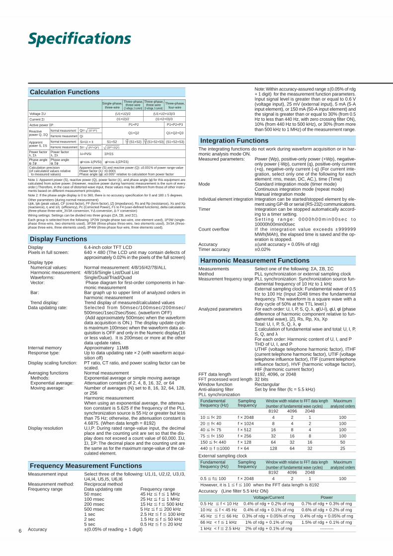
Calculation Functions
23
Single-phase,three-wire
Three-phase,three-wire
(2 voltage, 2 current)
Three-phase,three-wire
(3 voltage, 3 current)
Three-phase,four-wire
Voltage ΣU (U1+U2)/2 (U1+U2+U3)/3
(I1+I2)/2
P1+P2
S1+S2 (S1+S2) 33 (S1+S2+S3) (S1+S2+S3)
P1+P2+P3
Q1+Q2 Q1+Q2+Q3
(I1+I2+I3)/3Current ΣI
Active power ΣP
Reactivepower Q, ΣQ
Apparentpower S, ΣS
Power factorλ, ΣλPhase angleφ, Σφ
Power factorλ, Σλ λi=Pi/Si
φi=cos-1(Pi/Si) φi=cos-1(ΣP/ΣS)Phase angleφ, Σφ
Normal measurement
Harmonic measurement
Normal measurement
Harmonic measurement
Calculation precision(of calculated values relative to measured values)
Apparent power (S) and reactive power (Q): ±0.001% of power range-valuePower factor (λ): ±0.0001Phase angle (φ): ±0.005° relative to calculation from power factor
Qi=
Qi
(S2-P2)
Si=
Si=Ui × Ii
(Pi2+Qi2) (ΣP2+ΣQ2)
ΣP/ΣS
Note 1: Apparent power (S), reactive power (Q), power factor (λ), and phase angle (φ) for this equipment arecalculated from active power. (However, reactive power during harmonic measurement is the sum of everyorder.) Therefore, in the case of distorted-wave input, these values may be different from those of other instru-ments based on different measurement principles.Note 2: If the phase angle display is 0 to 360, there is no accuracy specification for 0 and 180 ± 5 degrees.Other parameters (during normal measurement)Upk, Ipk (peak value), CF (crest factor), FF (form factor), |Z| (impedance), Rs and Rp (resistance), Xs and Xp(reactance), η and 1/η (efficiency), Pc (Corrected Power), F1 to F4 (user-defined functions), delta calculations(three-phase three-wire_3V3A conversion, Y-∆ conversion, ∆-Y conversion)Wiring settings: Settings can be divided into three groups (ΣA, ΣB, and ΣC).Each group is selected from the following: 1P2W (single-phase two-wire, one element used), 1P3W (single-phase three-wire, two elements used), 3P3W (three-phase three-wire, two elements used), 3V3A (three-phase three-wire, three elements used), 3P4W (three-phase four-wire, three elements used).
Display FunctionsDisplay 6.4-inch color TFT LCDPixels in full screen: 640 × 480 (The LCD unit may contain defects of
approximately 0.02% in the pixels of the full screen)Display type Numerical values: Normal measurement: 4/8/16/42/78/ALL Harmonic measurement: 4/8/16/Single List/Dual List Waveforms: Single/Dual/Triad/Quad Vector: Phase diagram for first-order components in har-
monic measurement Bar: Bar graph up to upper limit of analyzed orders in
harmonic measurement Trend display: Trend display of measured/calculated valuesData updating rate: Selected from 50msec/100msec/200msec/
500msec/1sec/2sec/5sec. (waveform OFF) (Add approximately 500msec when the waveformdata acquisition is ON.) The display update cycleis maximum 100msec when the waveform data ac-quisition is OFF and only in the Numeric display(16or less value). It is 200msec or more at the otherdata update rates.
Internal memory Approximatery 11MBResponse type: Up to data updating rate × 2 (with waveform acqui-
sition off)Display scaling function: PT ratio, CT ratio, and power scaling factor can be
scaled.Averaging functions Normal measurement Methods: Exponential average or simple moving average Exponential average: Attenuation constant of 2, 4, 8, 16, 32, or 64 Moving average: Number of averages (N) set to 8, 16, 32, 64, 128,
or 256Harmonic measurementWhen using an exponential average, the attenua-tion constant is 5.625 if the frequency of the PLLsynchronization source is 55 Hz or greater but lessthan 75 Hz; otherwise, the attenuation constant is4.6875. (When data length = 8192)
Display resolution U,I,P: During rated range-value input, the decimalplace and the counting unit are set so that the dis-play does not exceed a count value of 60,000. ΣU,ΣI, ΣP: The decimal place and the counting unit arethe same as for the maximum range-value of the cal-culated element.
Frequency Measurement FunctionsMeasurement input Select three of the following: U1,I1, U2,I2, U3,I3,
U4,I4, U5,I5, U6,I6Measurement method: Reciprocal methodFrequency range Data updating rate Frequency range
50 msec 45 Hz f 1 MHz100 msec 25 Hz f 1 MHz200 msec 15 Hz f 500 kHz500 msec 5 Hz f 200 kHz1 sec 2.5 Hz f 100 kHz2 sec 1.5 Hz f 50 kHz5 sec 0.5 Hz f 20 kHz
Accuracy ±(0.05% of reading + 1 digit)
Note: Within accuracy-assured range ±(0.05% of rdg+ 1 digit) for the measurement function parameters.Input signal level is greater than or equal to 0.6 V(voltage input), 25 mV (external input), 5 mA (5-Ainput element), or 150 mA (50-A input element) andthe signal is greater than or equal to 30% (from 0.5Hz to less than 440 Hz, with zero crossing filter ON),10% (from 440 Hz to 500 kHz), or 30% (from morethan 500 kHz to 1 MHz) of the measurement range.
Integration FunctionsThe integrating functions do not work during waveform acquisition or in har-monic analysis mode ON.Measured parameters: Power (Wp), positive-only power (+Wp), negative-
only power (-Wp), current (q), positive-only current(+q), negative-only current (-q) (For current inte-gration, select only one of the following for eachelement: rms, mean, DC, AC.), time (Time)
Mode Standard integration mode (timer mode)Continuous integration mode (repeat mode)Manual integration mode
Individual element integration Integration can be started/stopped element by ele-ment using GP-IB or serial (RS-232) communications.
Timer Integration can be stopped automatically accord-ing to a timer setting.S e t t i n g r a n g e : 0 0 0 0 h 0 0 m i n 0 0 s e c t o10000h00min00sec
Count overflow If the integration value exceeds ±999999MWh(MAh), the elapsed time is saved and the op-eration is stopped.
Accuracy ±(unit accuracy + 0.05% of rdg)Timer accuracy ±0.02%
Harmonic Measurement FunctionsMeasurements Select one of the following: ΣA, ΣB, ΣCMethod PLL synchronization or external sampling clockMeasurement frequency range PLL synchronization: Synchronization source fun-
damental frequency of 10 Hz to 1 kHzExternal sampling clock: Fundamental wave of 0.5Hz to 100 Hz (Input 2048 times the fundamentalfrequency. The waveform is a square wave with aduty cycle of 50% at the TTL level.)
Analyzed parameters For each order: U, I, P, S, Q, λ, φ(U-I), φU, φI (phasedifference of harmonic component relative to fun-damental wave), |Z|, Rs, Rp, Xs, XpTotal: U, I, P, S, Q, λ, φΣ calculation of fundamental wave and total: U, I, P,S, Q, and λFor each order: Harmonic content of U, I, and PTHD of U, I, and PUTHF (voltage telephone harmonic factor), ITHF(current telephone harmonic factor), UTIF (voltagetelephone influence factor), ITIF (current telephoneinfluence factor), HVF (harmonic voltage factor),HIF (harmonic current factor)
FFT data length 8192, 4096, or 2048FFT processed word length 32 bitsWindow function RectangularAnti-aliasing filter Set by line filter (fc = 5.5 kHz)PLL synchronizationFundamental Sampling Window width relative to FFT data length Maximumfrequency (Hz) frequency (number of fundamental wave cycles) analyzed orders
8192 4096 2048
10 f< 20 f × 2048 4 2 1 10020 f< 40 f × 1024 8 4 2 10040 f< 75 f × 512 16 8 4 100
75 f< 150 f × 256 32 16 8 100150 f< 440 f × 128 64 32 16 50440 f 1000 f × 64 128 64 32 25
External sampling clockFundamental Sampling Window width relative to FFT data length Maximumfrequency (Hz) frequency (number of fundamental wave cycles) analyzed orders
8192 4096 20480.5 f 100 f × 2048 4 2 1 100
However, it is 1 f 100 when the FFT data length is 8192
Accuracy (Line filter 5.5 kHz ON)Voltage/Current Power
0.5 Hz f < 10 Hz 0.4% of rdg + 0.2% of rng 0.7% of rdg + 0.3% of rng10 Hz f < 45 Hz 0.4% of rdg + 0.1% of rng 0.6% of rdg + 0.2% of rng45 Hz f 66 Hz 0.3% of rdg + 0.05% of rng 0.4% of rdg + 0.05% of rng
66 Hz < f 1 kHz 1% of rdg + 0.1% of rng 1.5% of rdg + 0.1% of rng1 kHz < f 2.5 kHz 2% of rdg + 0.1% of rng ---------

7
D/A outputApproximately
7.5 V
5.0V
0.5V
2.5V
Displayvalue10Hz
1Hz0.5Hz
100Hz1kHz
10kHz100kHz
1MHz
Integrated values
D/A outputApproximately
7.0 V
5.0V
0
Integration time
tt0 values
In standard integration/continuous integration modes: Timer set timeIn manual integration mode: Integration D/A output set time
0
140% of rated input
Rated input
Other parameters
Display value Output
140% Approximately 7.0 V100% 5.0 V0% 0 V-100% -5.0 V -140% Approximately -7.0 V
D/A output
Approximately 7.5 VApproximately 7.0 V
5.0V
0
-5.0V
-100100
-140
140
Approximately -7.0 VApproximately -7.5 V
Display value (%)
Note that PF and deg are not output beyond the range of ±5.0 V. If an error occurs, approximately ±7.5 V are output. 0° to 360° are output at 0 to 5.0 V; LAG180° to LEAD180° are output at -5.0 V to 5.0 V.
Waveform Display FunctionsTriggers Mode Auto/Normal Type Edge Source U1, I1, U2, I2, U3, I3, U4, I4, U5, I5, U6, I6, external Slope Rising/falling/both Position 0% (fixed)Sample rate Approximately 200 kHzTime/Div 0.5 msec to 500 msec (not to exceed 1/10 of dis-
play updating period)Vertical zoom 0.1 to 100 timesData memory size 1 kW (Peak to peek compression data) The frequency that allows displaying of waveforms is up to approximately 10 kHz.
Built-in Printer (optional)
Printing method Thermal line-dotDot density 8 dots/mmPaper width 80 mmEffective recording width 72 mmRecorded information Screenshots, list of measured values, harmonic bar
graph printouts, settings
Ethernet (optional)
Transmission method Ethernet (10BASE-T)Supported services FTP server, FTP client, LPR (network printing),
SMTP (automatic mail transfer), DHCP, DNSElectrical and mechanical specifications
As per IEEE802.3Connector RJ-45 connector
Built-in Hard Drive (optional)
Capacity 10 GB (2 GB×5) IBM formatSCSI ID 4 (fixed)
External I/OEXT CLK (Sync source during normal measurement, PLL
source or external sampling clock during harmonicanalysis)
Connector BNC Input voltage TTL level
EXT MEAS.START(externa l measurement s tar t I /O) , EXTMEAS.STOP (external measurement stop I/O)
Connector BNC Synchronized measurement Connect the EXT MEAS.START terminal of the
master unit with the EXT MEAS.START terminalof the slave unit, and connect the EXT MEAS.STOPterminal of the master unit with the EXTMEAS.STOP terminal of the slave unit.
Internal floppy drive Size 3.5-inch Format 1.44 MBCommunication functions GP-IB or serial (RS-232) provided as a standard function. GP-IB interface
Electrical and mechanical specifications As per IEEE St’d 488-1978Functional specifications SH1, AH1, T6, L4, SR1, RL1, PR0, DC1, DT0, C0Protocol: As per IEEE St’d 488.2 1992
Serial (RS-232) interface Connector D-Sub 9-pin Specification EIA-574 (specifications for 9-pin interface in EIA-
232 (RS-232) standard) Transfer rate 1200, 2400, 4800, 9600, 19200 bpsVGA video output Connector type D-Sub 15-pin (VGA VIDEO OUT) Output format VGA-compatibleSCSI interface (optional) Specification SCSI(Small Computer System Interface)
ANSI X3.131-1986 Connector D-sub half-pitch 50-pin (pin type) Connector pin assignments Unbalanced (single-end), internal terminator
During nth-order component input, add (n/(m+1))/50% of the nth-order reading to (n-m)th order and(n+m)th order.
Line filter OFF For normal measurement accuracy, during nth-ordercomponent input, add (n/(m+1))/50% of the nth-or-der reading to (n-m)th order and (n+m)th order.Add (n/500)% of the nth-order reading to the nth-or-der component.
Motor Evaluation Functions (optional)
The motor evaluation functions do not work in harmonic measurement mode.Calculated parameters Torque, rpms, mechanical power, synchronization
speed, slip, motor efficiency, total efficiencyMeasured parameters Analog input for calculating torque and rpms
Input resistance Approximately 1MΩAccuracy ±(0.1% of rdg + 0.2% of rng)Input range-values 1/2/5/10/20 VEffective input range Up to ±110% of range-valueTemperature coefficient ±0.03% of rng/°C
Pulse input for rpm calculationInput resistance Approximately 1MΩAccuracy ±0.05% of rdg + 1 mHz + 1 digitInput range ±5 VpkEffective amplitude 1 Vp-p or higherInput waveform 50% duty ratio rectangular waveFrequency measurement range 2 Hz to 200 kHz
D/A Output (optional)
Number of outputs 30 parameters (each channel can be set separately)Accuracy ±(display accuracy +0.2% of F.S.)Maximum output current ±0.1 mATemperature coefficient ±0.05% of F.S./°COutput formatFrequency

Accessories (sold separately)
Product Model/ Description Orderpart number quantity
Rack mounting kit 751535-E4 For EIA 1Rack mounting kit 751535-J4 For JIS 1BNC cable 366924 BNC cable BNC-BNC (1 m) 1BNC cable 366925 BNC cable BNC-BNC (2 m) 1BNC cable 366926 BNC–alligator cable 1Adapter 366971 9-pin* to 25-pin** adapter 1Measurement leads 758917 Red and black, 75 cm; 2 leads in a set 1Fork terminal adapter set 758921 Converts fork terminal (4 mm) into banana 1
terminal; red and black (one each)
Alligator clips adapter 758922 Banana to alligator conversion; 2 in a set 1 (rated voltage: 300 V)Alligator clips adapter 758929 Banana to alligator conversion; 2 in a set 1(rated voltage: 1000 V)Fuses A1354EF 250 V, 6.3 Arms, time lag 100 V/200 V 2External sensor cable B9284LK For external input; 50 cm 1Roll paper for printer B9316FX Thermal paper; 10 meters (1 roll) 10
* The WT1600 unit cannot be purchased without any elements. Select an element type (5 A or 50 A) and quantity.Note: In order to add elements and options after the WT1600 has been delivered, the WT1600 must
be modified at the factory. Be aware of this in making your product selections. For furtherdetails, see Yokogawa's home page or contact our sales office.
*: EIA-574 standard**: EIA-232 standard (RS-232)
Subject to change without notice.[Ed : 03/b] Copyright ©2001
Printed in Japan, 203(YG)
YOKOGAWA ELECTRIC CORPORATIONTest and Measurement Business Div./Phone: (81)-55-243-0313, Fax: (81)-55-243-0396E-mail: [email protected] CORPORATION OF AMERICA Phone: (1)-770-253-7000, Fax: (1)-770-251-2088YOKOGAWA EUROPE B.V. Phone: (31)-33-4641806, Fax: (31)-33-4641807YOKOGAWA ENGINEERING ASIA PTE. LTD Phone: (65)-62419933, Fax: (65)-62412606 MS-12E
NOTICE Before operating the product, read the instruction manual thoroughly for
proper and safe operation. If this product is for use with a system requiring safeguards that directly
involve personnel safety, please contact the Yokogawa sales offices.
Element types and quantities
The numbers in the "Descrip-tion" column have the followingmeanings. 50: 50 A input element 5: 5 A input element Blank: No element
Elements are inserted in the or-der shown starting on the leftside on the back.
General SpecificationsSafety standard*1 Complying standard EN61010-1
Overvoltage category (Installation category) II*2
Pollution degree 2 *3
Emission *1 Complying standard EN61326 Class AEN61000-3-2EN61000-3-3AS/NZS 2064 Class A
Immunity *1 Complying standard EN61326 Annex A*4
Warmup time Approximately 1 hourOperating temperature and humidity ranges
5 to 40°C, 20 to 80%RH when not using the printer,5 to 40°C, 35 to 80%RH when using the printer.(nocondensation)
Storage temperature -25 to 60°C (no condensation)Operating elevation 2000 meters or lessInsulating resistance 50 MΩ or higher at 500 VDC
Between casing and power plugBetween voltage input terminals (ganged) and casingBetween current input terminals (ganged) and casingBetween voltage input terminals (ganged) and cur-rent input terminals (ganged)Between input terminals of each element.Between torque/speed input terminals (ganged) and casingBetween torque input terminals (ganged) and speedinput terminals (ganged)Between input terminals of each element.
Withstand voltage 1500 VAC for one minute at 50/60 HzBetween casing and power plug3700 VAC for one minute at 50/60 HzBetween voltage input terminals (ganged) and casingBetween current input terminals (ganged) and casingBetween voltage input terminals (ganged) and cur-rent input terminals (ganged)Between input terminals of each element.
Rated supply voltage 100 to 120 VAC, 200 to 240 VAC (switches automatically)Allowed supply voltage fluctuation range
90 to 132 VAC, 180 to 264 VACRated supply frequency 50/60 HzAllowed supply frequency fluctuation range
48 to 63 HzConsumed power Maximum 150 VA (when using internal printer)External dimensions Approximately 426 mm (W) × 177 mm (H) × 400 mm
(D) (excluding protrusions)Weight Approximately 15 kg (main unit with 6 input elements
and options installed)*1 Emission, immunity and safety standards apply to products having the CE Mark. For all other prod-
ucts, please contact your nearest YOKOGAWA representative as listed on the back cover of thismanual.
*2 Overvoltage Categories define transient overvoltage levels, including impulse withstand voltage lev-els. Overvoltage Category II: Applies to equipment supplied with electricity from fixed installationslike a distribution board.
*3 Pollution Degree: Applies to closed atmospheres (with no , or only dry, non-conductive pollution).Pollution Degree 2: Applies to normal indoor atmospheres (with only non-conductive pollution).
*4 Annex A (normative): Immunity test requirements for equipment intended for use in industrial locations.
Model and Suffix Codes
Model Suffix codes Description760101 WT1600 digital power meter main unit
Element Number1 2 3 4 5 6
-01 50-02 50 50-03 50 50 50-04 50 50 50 50-05 50 50 50 50 50-06 50 50 50 50 50 50-10 5-11 5 50-12 5 50 50-13 5 50 50 50-14 5 50 50 50 50-15 5 50 50 50 50 50-20 5 5-21 5 5 50-22 5 5 50 50-23 5 5 50 50 50-24 5 5 50 50 50 50-30 5 5 5-31 5 5 5 50-32 5 5 5 50 50-33 5 5 5 50 50 50-40 5 5 5 5-41 5 5 5 5 50-42 5 5 5 5 50 50-50 5 5 5 5 5-51 5 5 5 5 5 50-60 5 5 5 5 5 5
Communication -C1 GP-IBfunctions -C2 Serial (RS-232)Power cord -D UL/CSA Standard
-F VDE Standard -R SAA Standard -Q BS Standard
Option /B5 Internal printerspecifications /C7 SCSI interface
/C10 Ethernet, HDD, SCSI /DA 30-channel DA output /MTR Motor evaluation function
The TCP/IP software used in this product and the documentation for that TCP/IP soft-ware are based in part on BSD Networking Software, Release 1 licensed from The Re-gents of the University of California.
426
177
20
13 1317
23 377 28
Exterior (WT1600)
Unit: mm