digital selective-calling system for use in the maritime ... · recommendation itu-r m.493-14*...
TRANSCRIPT

Recommendation ITU-R M.493-14 (09/2015)
Digital selective-calling system for use in the maritime mobile service
M Series
Mobile, radiodetermination, amateur
and related satellite services

ii Rec. ITU-R M.493-14
Foreword
The role of the Radiocommunication Sector is to ensure the rational, equitable, efficient and economical use of the radio-
frequency spectrum by all radiocommunication services, including satellite services, and carry out studies without limit
of frequency range on the basis of which Recommendations are adopted.
The regulatory and policy functions of the Radiocommunication Sector are performed by World and Regional
Radiocommunication Conferences and Radiocommunication Assemblies supported by Study Groups.
Policy on Intellectual Property Right (IPR)
ITU-R policy on IPR is described in the Common Patent Policy for ITU-T/ITU-R/ISO/IEC referenced in Annex 1 of
Resolution ITU-R 1. Forms to be used for the submission of patent statements and licensing declarations by patent holders
are available from http://www.itu.int/ITU-R/go/patents/en where the Guidelines for Implementation of the Common
Patent Policy for ITU-T/ITU-R/ISO/IEC and the ITU-R patent information database can also be found.
Series of ITU-R Recommendations
(Also available online at http://www.itu.int/publ/R-REC/en)
Series Title
BO Satellite delivery
BR Recording for production, archival and play-out; film for television
BS Broadcasting service (sound)
BT Broadcasting service (television)
F Fixed service
M Mobile, radiodetermination, amateur and related satellite services
P Radiowave propagation
RA Radio astronomy
RS Remote sensing systems
S Fixed-satellite service
SA Space applications and meteorology
SF Frequency sharing and coordination between fixed-satellite and fixed service systems
SM Spectrum management
SNG Satellite news gathering
TF Time signals and frequency standards emissions
V Vocabulary and related subjects
Note: This ITU-R Recommendation was approved in English under the procedure detailed in Resolution ITU-R 1.
Electronic Publication
Geneva, 2016
ITU 2016
All rights reserved. No part of this publication may be reproduced, by any means whatsoever, without written permission of ITU.

Rec. ITU-R M.493-14 1
RECOMMENDATION ITU-R M.493-14*
Digital selective-calling system for use in the maritime mobile service
(1974-1978-1982-1986-1990-1992-1994-1995-1997-1997-2000-2004-2007-2009-2015)
Scope
This Recommendation describes the digital selective-calling (DSC) system for use in the maritime mobile
service covering general purpose and simplified versions of DSC equipment. A description of a generalized
user interface as well as an automated procedure for the operation of shipborne equipment are also included.
Keywords
Digital selective calling (DSC), maritime, GMDSS, distress, alert, announcement, class
Abbreviations/Glossary
dB Decibel
DSC Digital selective calling
ECC Error check character
EPIRB Emergency position-indicating radiobeacon
EOS End of sequence
HF High frequency
HMI Human machine interface
Hz Hertz
GMDSS Global maritime distress and safety system
ID Identification
IEC International electrotechnical commission
IMO International maritime organization
km Kilometre
MID Maritime identification digits
MF Medium frequency
MMSI Maritime mobile service identities
ms Millisecond
MSC Maritime safety committee
n/a This field is not included in this call
N North
____________________
* This Recommendation should be brought to the attention of the International Maritime Organization (IMO).

2 Rec. ITU-R M.493-14
NBDP Narrow-band direct-printing
NE North east
NM Nautical mile (1 NM = 1852 m)
NW North west
RT Radiotelephony
RX Retransmission
Rx Receive
S South
SE South east
SOLAS International Convention for the Safety of Life at Sea
SW South west
Tx Transmit
UTC Coordinated universal time
VHF Very high frequency
The ITU Radiocommunication Assembly,
considering
a) that selective-calling in the shore-to-ship, ship-to-ship and ship-to-shore directions would
expedite the handling of traffic in the maritime mobile service;
b) that the International Maritime Organization (IMO) has listed a number of operational
requirements that should be taken into account when designing a general purpose selective-calling
system;
c) that Chapter IV of the International Convention for the Safety of Life at Sea (SOLAS), 1974,
as amended, requires the use of digital selective calling (DSC) for distress alerting and safety calling
in the global maritime distress and safety system (GMDSS);
d) that the systems described in Recommendations ITU-R M.476 and ITU-R M.625, can not
fully meet the IMO performance standards for shipborne equipment;
e) that the DSC system should be applicable to the maritime mobile service, both for
international and national needs;
f) that it is desirable that the DSC system fulfils the requirements of all types of vessels desiring
to use it;
g) that after experience gained, a need exists to reduce unnecessary alarms and simplify
operation of shipborne equipment;
h) that in certain applications there may be a need to disable DSC automatic channel switching
when there is a requirement for vessels to maintain continuous radio watch on a specific radio
telephony channel (e.g. port traffic control, bridge-to-bridge communications),
Rec. ITU-R M.493-14 3
recommends
1 that devices or equipment which use DSC channels/frequencies should be in full compliance
with one of the defined classes within this Recommendation;
2 that DSC equipment should be designed in response to the operational requirements specified
within Recommendation ITU-R M.541;
3 that where there is a need for a general purpose DSC system, the system should be designed
in accordance with the characteristics given in Annex 1;
4 that where there is a need for simplified versions of DSC equipment, they should be designed
in accordance with Annex 2;
5 that shipborne DSC equipment should be designed to provide a simplified user interface,
following the examples of good practice set out in Annexes 3 and 4;
6 that in a GMDSS coast radio station installation, sufficient geographical separation should
be provided between the DSC distress channel receiver antennas and any transmitting antennas within
the installation. This is to avoid any de-sensitization of the DSC distress channel receivers if any
transmitter is used at full power on any designated transmit frequency other than the DSC distress
frequencies.
Annex 1
General purpose equipment characteristics
1 General
1.1 The system is a synchronous system using characters composed from a ten-bit error-detecting
code as listed in Table A1-1.
1.1.1 The first seven bits of the ten-bit code of Table A1-1 are information bits. Bits 8, 9 and
10 indicate, in the form of a binary number, the number of B elements that occur in the seven
information bits, a Y element being a binary number 1 and a B element a binary number 0. For
example, a BYY sequence for bits 8, 9 and 10 indicates 3 (0 4 1 2 1 1) B elements in the
associated seven information bit sequence; and a YYB sequence indicates 6 (1 4 1 2 0 1)
B elements in the associated seven information bit sequence. The order of transmission for the
information bits is least significant bit first but for the check bits it is most significant bit first.
1.2 Time diversity is provided in the call sequence as follows:
1.2.1 Apart from the phasing characters, each character is transmitted twice in a time-spread mode;
the first transmission (DX) of a specific character is followed by the transmission of four other
characters before the re-transmission (RX) of that specific character takes place, allowing for a time-
diversity reception interval of:
– 400 ms for HF and MF channels, and
– 33⅓ ms for VHF radio-telephone channels.

4 Rec. ITU-R M.493-14
1.3 The classes of emission, frequency shifts and modulation rates are as follows:
1.3.1 F1B or J2B 170 Hz and modulation rate of 100 (bit/s) * (1 ± 30 * 10-6) for use on HF and MF
DSC calling channels. When frequency-shift keying is effected by applying audio signals to the input
of single-sideband transmitters (J2B), the centre of the audio-frequency spectrum offered to the
transmitter is 1 700 Hz. When a DSC call is transmitted on HF and MF working channels for public
correspondence, the class of emission is J2B. In this case, audio tones with frequencies
1 700 Hz 85 Hz and modulation rate 100 (bit/s) * (1 ± 30 * 10−6) are used in order for the DSC call
to be transmitted.
1.3.2 Frequency modulation with a pre-emphasis of 6 dB/octave (phase modulation) with
frequency-shift of the modulating sub-carrier for use on VHF channels:
– frequency-shift between 1 300 and 2 100 Hz; the sub-carrier being at 1 700 Hz;
– the frequency tolerance of the 1 300 and 2 100 Hz tones is 10 Hz;
– the modulation rate is 1 200 (bit/s) * (1 ± 30 * 10−6);
– the index of modulation is 2.0 10%.
1.3.3 The radio-frequency tolerances of new designs of both transmitters and receivers in the MF
and HF bands should be:
– coast station: 10 Hz,
– ship station: 10 Hz,
– receiver bandwidth: should not exceed 300 Hz.
1.4 The higher frequency corresponds to the B-state and the lower frequency corresponds to the
Y-state of the signal elements.
1.5 The information in the call is presented as a sequence of seven-bit combinations constituting
a primary code.
1.5.1 The seven information bits of the primary code express a symbol number from 00 to 127, as
shown in Table A1-1, and where:
– the symbols from 00 to 99 are used to code two decimal figures according to Table A1-2;
– the symbols from 100 to 127 are used to code service commands (see Table A1-3).
1.6 Where the distress alert repetitions described in § 11 apply, the following conditions are
considered necessary:
1.6.1 the transmitter encoder must provide repetitive transmission of the call sequence in
accordance with § 11; and
1.6.2 the receiver decoder should provide maximum utilization of the received signal, including
use of the error-check character and by using an iterative decoding process with adequate memory
provision.
1.7 When the transmission of a DSC distress alert is automatically repeated, ships’ DSC
equipment must be capable of automatically receiving a subsequent distress acknowledgement
(see Recommendation ITU-R M.541).

Rec. ITU-R M.493-14 5
TABLE A1-1
Ten-bit error-detecting code
Symbol
No.
Emitted signal
and bit position
1 2 3 4 5 6 7 8 9 10
Symbol
No.
Emitted signal
and bit position
1 2 3 4 5 6 7 8 9 10
Symbol
No.
Emitted signal
and bit position
1 2 3 4 5 6 7 8 9 10
00
01
02
03
04
05
06
07
08
09
10
11
12
13
14
15
16
17
18
19
20
21
22
23
24
25
26
27
28
29
30
31
32
33
34
35
36
37
38
39
40
41 42
BBBBBBBYYY
YBBBBBBYYB
BYBBBBBYYB
YYBBBBBYBY
BBYBBBBYYB
YBYBBBBYBY
BYYBBBBYBY
YYYBBBBYBB
BBBYBBBYYB
YBBYBBBYBY
BYBYBBBYBY
YYBYBBBYBB
BBYYBBBYBY
YBYYBBBYBB
BYYYBBBYBB
YYYYBBBBYY
BBBBYBBYYB
YBBBYBBYBY
BYBBYBBYBY
YYBBYBBYBB
BBYBYBBYBY
YBYBYBBYBB
BYYBYBBYBB
YYYBYBBBYY
BBBYYBBYBY
YBBYYBBYBB
BYBYYBBYBB
YYBYYBBBYY
BBYYYBBYBB
YBYYYBBBYY
BYYYYBBBYY
YYYYYBBBYB
BBBBBYBYYB
YBBBBYBYBY
BYBBBYBYBY
YYBBBYBYBB
BBYBBYBYBY
YBYBBYBYBB
BYYBBYBYBB
YYYBBYBBYY
BBBYBYBYBY
YBBYBYBYBB BYBYBYBYBB
43
44
45
46
47
48
49
50
51
52
53
54
55
56
57
58
59
60
61
62
63
64
65
66
67
68
69
70
71
72
73
74
75
76
77
78
79
80
81
82
83
84 85
YYBYBYBBYY
BBYYBYBYBB
YBYYBYBBYY
BYYYBYBBYY
YYYYBYBBYB
BBBBYYBYBY
YBBBYYBYBB
BYBBYYBYBB
YYBBYYBBYY
BBYBYYBYBB
YBYBYYBBYY
BYYBYYBBYY
YYYBYYBBYB
BBBYYYBYBB
YBBYYYBBYY
BYBYYYBBYY
YYBYYYBBYB
BBYYYYBBYY
YBYYYYBBYB
BYYYYYBBYB
YYYYYYBBBY
BBBBBBYYYB
YBBBBBYYBY
BYBBBBYYBY
YYBBBBYYBB
BBYBBBYYBY
YBYBBBYYBB
BYYBBBYYBB
YYYBBBYBYY
BBBYBBYYBY
YBBYBBYYBB
BYBYBBYYBB
YYBYBBYBYY
BBYYBBYYBB
YBYYBBYBYY
BYYYBBYBYY
YYYYBBYBYB
BBBBYBYYBY
YBBBYBYYBB
BYBBYBYYBB
YYBBYBYBYY
BBYBYBYYBB YBYBYBYBYY
86
87
88
89
90
91
92
93
94
95
96
97
98
99
100
101
102
103
104
105
106
107
108
109
110
111
112
113
114
115
116
117
118
119
120
121
122
123
124
125
126
127
BYYBYBYBYY
YYYBYBYBYB
BBBYYBYYBB
YBBYYBYBYY
BYBYYBYBYY
YYBYYBYBYB
BBYYYBYBYY
YBYYYBYBYB
BYYYYBYBYB
YYYYYBYBBY
BBBBBYYYBY
YBBBBYYYBB
BYBBBYYYBB
YYBBBYYBYY
BBYBBYYYBB
YBYBBYYBYY
BYYBBYYBYY
YYYBBYYBYB
BBBYBYYYBB
YBBYBYYBYY
BYBYBYYBYY
YYBYBYYBYB
BBYYBYYBYY
YBYYBYYBYB
BYYYBYYBYB
YYYYBYYBBY
BBBBYYYYBB
YBBBYYYBYY
BYBBYYYBYY
YYBBYYYBYB
BBYBYYYBYY
YBYBYYYBYB
BYYBYYYBYB
YYYBYYYBBY
BBBYYYYBYY
YBBYYYYBYB
BYBYYYYBYB
YYBYYYYBBY
BBYYYYYBYB
YBYYYYYBBY
BYYYYYYBBY
YYYYYYYBBB
B = 0
Y = 1 Order of bit transmission: bit 1 first.

6 Rec. ITU-R M.493-14
TABLE A1-2
Packing table for decimal numbers into ten-bit characters
The digits for the
Thousands
of millions
D2
Hundreds
of millions
D1
Tens of
millions
D2
Millions
D1
Hundreds of
thousands
D2
Tens of
thousands
D1
Thousand
s
D2
Hundred
s
D1
Tens
D2
Units
D1
Character 5 Character 4 Character 3 Character 2 Character 1
NOTE 1 – Character 1 is the last character transmitted.
The digit sequence D2-D1 varies from 00 to 99 inclusive in each character (character 1 to 5 inclusive). The character that represents a
particular two-decimal figure is transmitted as the symbol number (see Table A1-1) that is identical to that particular two-decimal
figure.
When the number consists of an odd number of decimal digits, a zero shall be added in front of the most significant position to provide
an integral number of ten-bit characters.
TABLE A1-3
Use of symbol Nos. 100 to 127
Symbol
No.
Phasing
and unique
functions
Format specifier(1) Category(1) Nature of
distress(1)
First
telecommand(1) Second
telecommand(1)
100 Routine Fire, explosion F3E/G3E All modes TP
No reason given(2)
101 Flooding F3E/G3E duplex TP
Congestion at maritime switching centre
102 Geographical area Collision Busy(2)
103 (3) (3) Grounding Polling Queue indication(2)
104 Phasing
RX-0 position
Listing, in
danger of capsizing
Unable to comply Station barred(2)
105 Phasing
RX-1 position
Sinking End of call(4) No operator available(2)
106 Phasing
RX-2 position
(6) Disabled and
adrift
Data Operator temporarily
unavailable(2)
107 Phasing
RX-3 position
Undesignated
distress
Equipment disabled(2)
108 Phasing
RX-4
position
Safety Abandoning ship
Unable to use proposed channel(2)
109 Phasing
RX-5 position
Piracy/armed
robbery attack
J3E TP Unable to use proposed
mode(2)
110 Phasing
RX-6 position
(5) Urgency Man overboard Distress
acknowledgement
Ships and aircraft of
States not parties to an armed conflict

Rec. ITU-R M.493-14 7
TABLE A1-3 (end)
Symbol
No.
Phasing
and unique
functions
Format specifier(1) Category(1) Nature of
distress(1)
First
telecommand(1) Second
telecommand(1)
111 Phasing
RX-7 position
(6) Medical transports
(as defined in 1949
Geneva Conventions and additional Protocols)A
112 Distress Distress EPIRB
emissionB
Distress alert
relay
Pay-phone/public call
officeC
113 F1B/J2B
TTY-FEC
Facsimile/data according
to Recommendation ITU-R M.1081
114 Ships having
common interest
115 F1B/J2B
TTY-ARQ
(6)
116 All ships(7) (6) (6)
117 Ack. RQ
(EOS)
(6) (6)
118 Test (6)
119 (6) (6)
120 Individual stations (6) (6)
121 Reserved for
national
non-calling
purposes e.g.
Report ITU-R M.1159
Ship position
or location
registration
updating
(6)
122 Ack. BQ
(EOS)
(6) (6)
123 Individual station
semi-automatic/ automatic serviceC
(6) (6)
124 (5) (6) (6)
125 Phasing DX
position
(6) (6)
126 * No information No information
127 EOS (6) (6)
TP: Telephony
TTY: Direct printing
ARQ: Recommendations ITU-R M.476 or ITU-R M.625 equipment
(1) Unassigned symbols should be rejected. The DSC equipment should take no action.
(2) Currently unassigned when used with first telecommands other than symbol No. 104 – for future use.
(3) Used for selective call to a group of ships in a specified VTS area (Rec. ITU-R M.825). Reception of calls having format specifier
103, for (or) category shall not activate any alarms on shipborne DSC controller. Should not be used in any future expansion.
(4) Only used for semi-automatic/automatic service.
(5) Used in the automatic VHF/UHF service (Rec. ITU-R M.586). Should not be used in any future expansion.
(6) Should not be used in any future expansion.
(7) MF/HF used only for distress alert acknowledgment and coast station receive (see Table A1-4).
8 Rec. ITU-R M.493-14
Notes relative to Table A1-3 (cont.):
A – NOTE – The telecommands for “Ships and aircraft of States not parties to an armed conflict” and “Medical transports (as defined
in 1949 Geneva Conventions and additional Protocols)” are laid down in binding conventions and protocols which should not be
touched by the any change of Rec. ITU-R M.493.
B – NOTE – The VHF EPIRB can be used to comply with an IMO carriage requirement – prior to deletion it should be deleted from
the relevant chapter of SOLAS – this would require a new work item.
C – NOTE – The deletion of certain telecommands is a major change in the system, such as codes for the connection the fixed network
information about the worldwide implementation should be sought by sending a circular letter to administrations. The result and
further requests for the deletion should be brought to the attention of the IMO Correspondence Group for the revision of
the GMDSS.
“*” Symbol transmitted in place of unused message information.
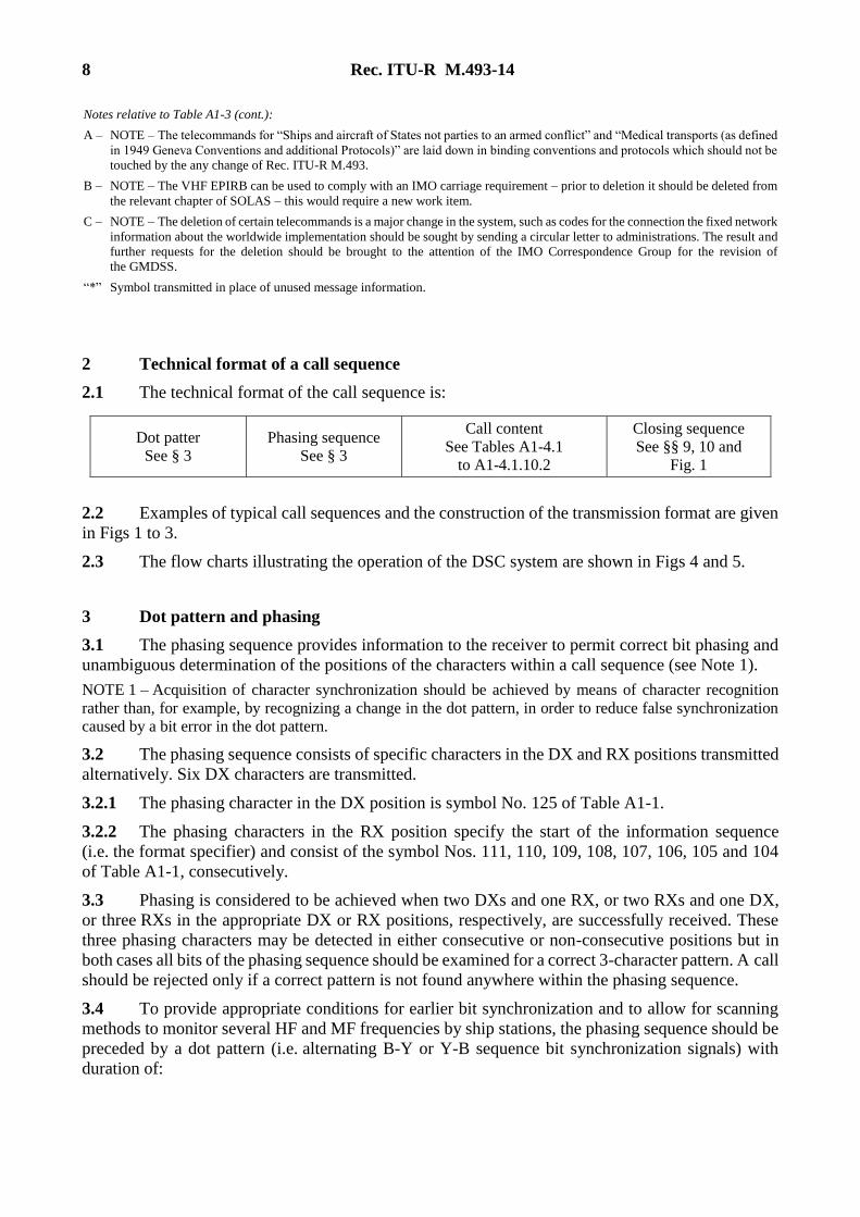
2 Technical format of a call sequence
2.1 The technical format of the call sequence is:
Dot patter
See § 3
Phasing sequence
See § 3
Call content
See Tables A1-4.1
to A1-4.1.10.2
Closing sequence
See §§ 9, 10 and
Fig. 1
2.2 Examples of typical call sequences and the construction of the transmission format are given
in Figs 1 to 3.
2.3 The flow charts illustrating the operation of the DSC system are shown in Figs 4 and 5.
3 Dot pattern and phasing
3.1 The phasing sequence provides information to the receiver to permit correct bit phasing and
unambiguous determination of the positions of the characters within a call sequence (see Note 1).
NOTE 1 – Acquisition of character synchronization should be achieved by means of character recognition
rather than, for example, by recognizing a change in the dot pattern, in order to reduce false synchronization
caused by a bit error in the dot pattern.
3.2 The phasing sequence consists of specific characters in the DX and RX positions transmitted
alternatively. Six DX characters are transmitted.
3.2.1 The phasing character in the DX position is symbol No. 125 of Table A1-1.
3.2.2 The phasing characters in the RX position specify the start of the information sequence
(i.e. the format specifier) and consist of the symbol Nos. 111, 110, 109, 108, 107, 106, 105 and 104
of Table A1-1, consecutively.
3.3 Phasing is considered to be achieved when two DXs and one RX, or two RXs and one DX,
or three RXs in the appropriate DX or RX positions, respectively, are successfully received. These
three phasing characters may be detected in either consecutive or non-consecutive positions but in
both cases all bits of the phasing sequence should be examined for a correct 3-character pattern. A call
should be rejected only if a correct pattern is not found anywhere within the phasing sequence.
3.4 To provide appropriate conditions for earlier bit synchronization and to allow for scanning
methods to monitor several HF and MF frequencies by ship stations, the phasing sequence should be
preceded by a dot pattern (i.e. alternating B-Y or Y-B sequence bit synchronization signals) with
duration of:

Rec. ITU-R M.493-14 9
3.4.1 200 bits
At HF and MF for:
– distress alerts;
– distress acknowledgements;
– distress alert relays addressed to a geographic area;
– distress alert relay acknowledgements addressed to all ships;
– all calls addressed to a ship station other than those specified in § 3.4.2.
3.4.2 20 bits
At HF and MF for:
– all acknowledgements to individual calls having format specifiers 120 and 123;
– all calling to coast stations.
At VHF for all calls.
4 Format specifier
4.1 The format specifier characters which are transmitted twice in both the DX and RX positions
(see Fig. 1) are:
– symbol No. 112 for a “distress” alert; or
– symbol No. 116 for an “all ships” call; or
– symbol No. 114 for a selective call to a group of ships having a common interest
(e.g. belonging to one particular country, or to a single ship owner, etc.); or
– symbol No. 120 for a selective call to a particular individual station; or
– symbol No. 102 for a selective call to a group of ships in a particular geographic area; or
– symbol No. 123 for a selective call to a particular individual station using the semi-
automatic/automatic service.
4.2 It is considered that receiver decoders must detect the format specifier character twice for
“distress” alerts and “all ships” calls to effectively eliminate false alerting. For other calls, the address
characters provide additional protection against false alerting and, therefore, single detection of the
format specifier character is considered satisfactory (see Table A1-3).
5 Address
5.1 “Distress” alerts and “all ships” calls do not have addresses since these calls are implicitly
addressed to all stations (ship stations and coast stations).
5.2 For a selective call directed to an individual ship, to a coast station or to a group of stations
having a common interest, the address consists of the characters corresponding to the station’s
maritime identity as defined in Recommendation ITU-R M.585. The sequence consists of characters
coded in accordance with Table A1-2 (see Note 1).
NOTE 1 – According to RR Article 19, maritime mobile service identities are formed of a series of nine digits,
consisting of three digits of the maritime identification digits (MID) and six more digits.

10 Rec. ITU-R M.493-14
These identities are included in the address and self-identification parts of the call sequence and are transmitted
as five characters C5C4C3C2C1, comprising the ten digits of:
(X1, X2) (X3, X4) (X5, X6) (X7, X8) and (X9, X10)
respectively, whereas digit X10 is always the digit 0 unless the equipment is also designed in accordance with
Recommendation ITU-R M.1080.
Example:
MID X4 X5 X6 X7 X8 X9 being the ship station identity is transmitted by the DSC equipment as:
(M, I) (D, X4) (X5, X6) (X7, X8) (X9, 0)
5.3 For a selective call directed to a group of ships in a particular geographic area a numerical
geographic coordinates address consisting of ten digits (i.e. 5 characters), is constructed as follows
(see Fig. 6 and Note 1):
NOTE 1 – In order to comply with commonly accepted practice, the order of entry and read-out should be:
first latitude and then longitude.
1 the designated geographic area will be a rectangle in Mercator projection;
2 the upper left-hand (i.e. North-West) corner of the rectangle is the reference point for the
area;
3 the first digit indicates the azimuth sector in which the reference point is located, as follows:
– quadrant NE is indicated by the digit “0”,
– quadrant NW is indicated by the digit “1”,
– quadrant SE is indicated by the digit “2”,
– quadrant SW is indicated by the digit “3”;
4 the second and third digits indicate the latitude of the reference point in tens and units of
degrees;
5 the fourth, fifth and sixth digits indicate the longitude of the reference point in hundreds, tens
and units of degrees;
6 the seventh and eighth digits indicate the vertical (i.e. North-to-South) side of the rectangle,
, in tens and units of degrees;
7 the ninth and tenth digits indicate the horizontal (i.e. West-to-East) side of the rectangle, ,
in tens and units of degrees.
6 Category
The “category” information is coded as shown in Table A1-3 and defines the degree of priority of the
call sequence.
6.1 For a “distress” alert the priority is defined by the format specifier and no category
information is included in the call sequence.
For distress alert relays, distress alert relay acknowledgements and distress acknowledgements the
category is distress.

Rec. ITU-R M.493-14 11
6.2 For safety related calls, the “category” information specifies:
– urgency; or
– safety.
6.3 For other calls, the “category” information specifies:
– routine.
7 Self-identification
7.1 The maritime identity as defined in Recommendation ITU-R M.585, coded as indicated
in § 5.2 and its Note 1, is used for self-identification.
8 Messages
The messages that are included in a call sequence contain the following message elements, which are
listed in the order in which they would appear in each message. All message formats are explicitly
defined in Tables A1-4.1 through A1-4.11:
8.1 For a “distress” alert (see Table A1-4.1) the distress information is contained in four
messages in the following order:
8.1.1 Message 1
Message 1 is the “nature of distress” message, coded as shown in Table A1-3, i.e.:
– 100 fire, explosion;
– 101 flooding;
– 102 collision;
– 103 grounding;
– 104 listing, in danger of capsizing;
– 105 sinking;
– 106 disabled and adrift;
– 107 undesignated distress;
– 108 abandoning ship;
– 109 piracy/armed robbery attack;
– 110 man overboard;
– 111 emergency position-indicating radiobeacon (EPIRB) emission.
8.1.2 Message 2
Message 2 is the “distress coordinates” message, consisting of ten digits indicating the location of the
vessel in distress, coded on the principles described in Table A1-2, in pairs starting from the first and
second digits (see Note 1 to § 5.3):
– The first digit indicates the quadrant in which the incident has occurred, as follows:
– quadrant NE is indicated by the digit “0”,
– quadrant NW is indicated by the digit “1”,
– quadrant SE is indicated by the digit “2”,
– quadrant SW is indicated by the digit “3”.

12 Rec. ITU-R M.493-14
– The next four figures indicate the latitude in degrees and minutes.
– The next five figures indicate the longitude in degrees and minutes.
– If “distress coordinates” cannot be included, or if the position information has not been
updated for 23½ h, the 10 digits following the “nature of distress” should be automatically
transmitted as the digit 9 repeated 10 times.
8.1.3 Message 3
Message 3 is the time indication coordinated universal time (UTC) when the coordinates were valid
consisting of four digits coded on the principles described in Table A1-2, in pairs starting from the
first and second digits.
– The first two digits indicate the time in hours.
– The third and fourth digits indicate the part of the hours in minutes.
– If the time cannot be included the four time indicating digits should be transmitted
automatically as “8 8 8 8”.
8.1.4 Message 4
Message 4 is a single character to indicate the type of communication (telephone or FEC teleprinter)
which is preferred by the station in distress for subsequent exchange of distress traffic. This character
is coded as shown in Table A1-3 first telecommand.
8.2 Distress alert relay, distress alert relay acknowledgement, distress acknowledgement
For a distress alert relay, distress alert relay acknowledgement, distress acknowledgement (see
Tables A1-4.2, A1-4.3 and A1-4.4) the distress information is contained in five messages in the
following order:
8.2.1 Message 0
Message 0 is the maritime identity of the unit in distress as defined in Recommendation ITU-R M.585.
8.2.2 Message 1
Message 1 is the “nature of distress” message, coded as shown in Table A1-3, i.e.:
– 100 fire, explosion;
– 101 flooding;
– 102 collision;
– 103 grounding;
– 104 listing, in danger of capsizing;
– 105 sinking;
– 106 disabled and adrift;
– 107 undesignated distress;
– 108 abandoning ship;
– 109 piracy/armed robbery attack;
– 110 man overboard;
– 111 emergency position-indicating radiobeacon (EPIRB) emission.

Rec. ITU-R M.493-14 13
8.2.3 Message 2
Message 2 is the “distress coordinates” message, consisting of ten digits indicating the location of the
vessel in distress, coded on the principles described in Table A1-2, in pairs starting from the first and
second digits (see Note 1 to § 5.3):
– The first digit indicates the quadrant in which the incident has occurred, as follows:
– quadrant NE is indicated by the digit “0”,
– quadrant NW is indicated by the digit “1”,
– quadrant SE is indicated by the digit “2”,
– quadrant SW is indicated by the digit “3”.
– The next four figures indicate the latitude in degrees and minutes.
– The next five figures indicate the longitude in degrees and minutes.
If “distress coordinates” cannot be included, or if the position information has not been updated
for 23½ h, the 10 digits following the “nature of distress” should be automatically transmitted as the
digit 9 repeated 10 times.
8.2.4 Message 3
Message 3 is the time indication (UTC) when the coordinates were valid consisting of four digits
coded on the principles described in Table A1-2, in pairs starting from the first and second digits.
– The first two digits indicate the time in hours.
– The third and fourth digits indicate the part of the hours in minutes.
– If the time cannot be included the four time indicating digits should be transmitted
automatically as “8 8 8 8”.
8.2.5 Message 4
Message 4 is a single character to indicate the type of communication (telephone or FEC teleprinter)
which is preferred by the station in distress for subsequent exchange of distress traffic. This character
is coded as shown in Table A1-3 first telecommand.
8.3 Other types of calls
For other types of calls (see Table A1-4.5 through A1-4.11 and Figs 3 and 4) messages are included
in the following order:
8.3.1 Message 1
Message 1 is the “telecommand” information and consists of 2 characters (first and second
telecommand) coded as shown in Table A1-3:
– if no information additional to that conveyed by the first telecommand character is required,
then the second telecommand signal should be symbol No. 126 (no information) (see
Table A1-3);
– if no telecommand information is used, symbol No. 126 is transmitted twice;
– if the telecommand 1 is “F3E/G3E duplex TP” (symbol 101) in a request, which can be
complied with, the telecommand 1 “F3E/G3E all modes TP” (symbol 100) should be used in
the acknowledgement.

14 Rec. ITU-R M.493-14
second frequency element (the Tx field) indicates the called station transmit frequency. In
acknowledgements the Rx and Tx fields indicate the receive and transmit frequency of the
acknowledging station respectively (see also Fig. 2 and Note 1).
NOTE 1 – If only one channel or frequency message element is used, this indicates the called station receive
channel or frequency or a two-frequency (paired) channel. A second channel or frequency message element
may be used to designate the called station transmit channel or frequency. If the calling station indicates only
the called station receive frequency (for broadcast mode transmissions) then the symbol No. 126 repeated three
times (see Note 2) should be transmitted instead of the called station transmit channel or frequency message
element. If no “channel or frequency message” elements are used, the symbol No. 126 is transmitted six times.
For calls using the semi-automatic/automatic VHF service (see Table A1-4.10.1) then only one “channel or
frequency message” element is transmitted which indicates the paired channel number. In the absence of this
element the symbol No. 126 should be transmitted three times.
NOTE 2 – In the F1B/J2B mode (FEC or ARQ), if using seven-digit frequency as the working frequency,
Message 2 may contain two frequency message elements as mentioned above, but each of which consists of
four characters, “character 0”, “character 1”, “character 2” and “character 3” in multiples of 10 Hz (coded in
accordance with Table A1-5). Additionally if the calling station indicates only the called station receive
frequency of seven-digit (for broadcast mode transmissions) then the symbol No. 126 repeated four times
should be transmitted instead of the called station transmit frequency message element.
8.3.2.1 Frequency information
The frequency (in the F1B/J2B mode the assigned frequency should be used) in multiples of 100 Hz
or 10 Hz (see Note 2 above) may only be indicated as such when the frequency is below 30 MHz.
The three characters provide for the required six decimal digits. Character 1 represents the units (U)
and tens (T) of 100 Hz, character 2 the hundreds (H) and thousands (M) and character 3 the tens of
thousands (TM) and hundreds of thousands (HM) of 100 Hz. For MF/HF DSC, use frequency
selection mode, vice channel selection mode, to ensure international interoperability. Also, when
using seven-digit frequencies, the four characters provide for the required seven decimal digits.
Character 0 represents the units (U1) and tens (T1) of 10 Hz, character 1 the units (U) and tens (T) of
1 kHz, character 2 the hundreds (H) and thousands (M) and character 3 the tens of thousands (TM)
of 1 kHz. However note that this four characters information is only for use of seven-digit frequencies
in the F1B/J2B, i.e. it does not affect the messages for the J3E TP mode and for the F1B/J2B mode
using six-digit frequencies to ensure interoperability.
8.3.2.2 Channel information
8.3.2.2.1 HF and MF channels
If the HM digit is 3, this indicates that the number represented by the digits TM, M, H, T, U, T1 and
U1 is the HF/MF working channel number (either single frequency or two frequency channels). This
mode should only be used for decoding received calls, to ensure interoperability with older
equipment.
8.3.2.2.2 VHF channels
If the HM digit is 9, this indicates that the number represented by the values of the digits M, H, T and
U is the VHF working channel number. If the M digit is 1, this indicates that the ship stations
transmitting frequency is being used as a simplex channel frequency for both ship and coast stations.
If the M digit is 2, this indicates that the coast stations transmitting frequency is being used as a
simplex channel frequency for both ship and coast stations.

Rec. ITU-R M.493-14 15
8.3.2.3 Ship’s position information
For MF/HF calls, message 2 may contain the ship’s position, consisting of the digit 5 repeated two
times and ten digits (five characters) indicating this position, coded in accordance with § 8.1.2 (see
Table A1-6).
For position requests message 2 consists of 6 no information symbols (symbol No. 126).
In acknowledgements to a call requesting ship’s position (see Fig. 3d)) message 2 consists of twelve
digits (six symbols), the first of which should be coded in accordance with § 8.1.2 followed by one
symbol No. 126.
8.3.3 Message 3
Message 3 follows message 2 in this case and contains the time (UTC) when the coordinates were
valid, coded as indicated in § 8.1.3.
Message 3 follows message 2 when using the DSC system for calls initiated by ship stations requiring
a semi-automatic or automatic connection (see Table A1-4.10.1 and A1-4.10.2) and contains the
public switched network number (e.g. telephone number). In this case the format specifier used is
symbol No. 123.
This number is coded by up to nine symbols in a manner similar to that shown in Table A1-2, except
that the first character transmitted should be either symbol No. 105 or No. 106 to indicate whether
the network number contains an odd or even number of significant digits. As an example, the number
0012345 would be coded as symbol numbers 105 00 01 23 45 whereas the number 00123456 should
be coded as symbol numbers 106 00 12 34 56.
8.4 Distress alert relay
For “distress alert relay” including shore-to-ship alerts, “distress alert relay acknowledgement” and
“distress acknowledgement” calls, the message formats are indicated in Tables A1-4.3, A1-4.4 and
A1-4.2 respectively.
When sending a distress alert on behalf of another ship which is unable to send its own alert, and
where the identity of the station in distress is unknown, the distress alert relay call should contain the
symbol No. 126 transmitted five times for the “identification of the station in distress”.
8.5 Test calls
Test calls on the distress and safety frequencies for MF and HF and VHF channel 70 may be
conducted using the test call sequence in Table A1-4.7.
8.6 Distress self-cancel operation
Distress acknowledgments where the transmitting ID and ship in distress ID are the same,
the message should be interpreted as a self-cancel operation. This should be displayed on all receiving
stations.
16 Rec. ITU-R M.493-14
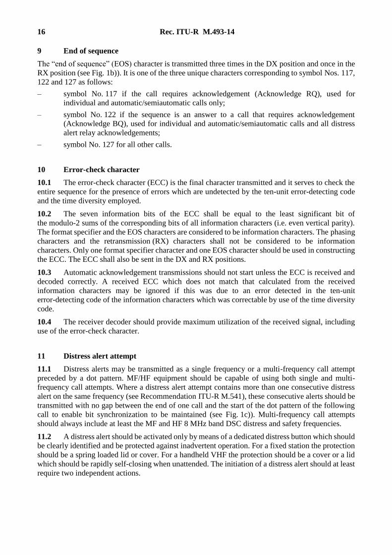
9 End of sequence
The “end of sequence” (EOS) character is transmitted three times in the DX position and once in the
RX position (see Fig. 1b)). It is one of the three unique characters corresponding to symbol Nos. 117,
122 and 127 as follows:
– symbol No. 117 if the call requires acknowledgement (Acknowledge RQ), used for
individual and automatic/semiautomatic calls only;
– symbol No. 122 if the sequence is an answer to a call that requires acknowledgement
(Acknowledge BQ), used for individual and automatic/semiautomatic calls and all distress
alert relay acknowledgements;
– symbol No. 127 for all other calls.
10 Error-check character
10.1 The error-check character (ECC) is the final character transmitted and it serves to check the
entire sequence for the presence of errors which are undetected by the ten-unit error-detecting code
and the time diversity employed.
10.2 The seven information bits of the ECC shall be equal to the least significant bit of
the modulo-2 sums of the corresponding bits of all information characters (i.e. even vertical parity).
The format specifier and the EOS characters are considered to be information characters. The phasing
characters and the retransmission (RX) characters shall not be considered to be information
characters. Only one format specifier character and one EOS character should be used in constructing
the ECC. The ECC shall also be sent in the DX and RX positions.
10.3 Automatic acknowledgement transmissions should not start unless the ECC is received and
decoded correctly. A received ECC which does not match that calculated from the received
information characters may be ignored if this was due to an error detected in the ten-unit
error-detecting code of the information characters which was correctable by use of the time diversity
code.
10.4 The receiver decoder should provide maximum utilization of the received signal, including
use of the error-check character.
11 Distress alert attempt
11.1 Distress alerts may be transmitted as a single frequency or a multi-frequency call attempt
preceded by a dot pattern. MF/HF equipment should be capable of using both single and multi-
frequency call attempts. Where a distress alert attempt contains more than one consecutive distress
alert on the same frequency (see Recommendation ITU-R M.541), these consecutive alerts should be
transmitted with no gap between the end of one call and the start of the dot pattern of the following
call to enable bit synchronization to be maintained (see Fig. 1c)). Multi-frequency call attempts
should always include at least the MF and HF 8 MHz band DSC distress and safety frequencies.
11.2 A distress alert should be activated only by means of a dedicated distress button which should
be clearly identified and be protected against inadvertent operation. For a fixed station the protection
should be a spring loaded lid or cover. For a handheld VHF the protection should be a cover or a lid
which should be rapidly self-closing when unattended. The initiation of a distress alert should at least
require two independent actions.

Rec. ITU-R M.493-14 17
11.3 Calls with format specifier “distress” or category “distress”, “urgency” and “safety” should
be initiated manually only. This applies also for ships equipped for automatic DSC operation.
For automatic repetition of distress alerts see Recommendation ITU-R M.541.
11.4 Immediately following a distress alert a DSC expansion message giving enhanced position
resolution according to Recommendation ITU-R M.821 should be transmitted in the following
manner.
For a single frequency distress alert attempt the expansion message should be transmitted
immediately after the last of five consecutive distress alerts.
For a multi-frequency distress alert attempt the expansion message should be transmitted immediately
after each distress alert.
12 Shipborne human machine interface
12.1 Shipborne aural alarm
Shipborne alarms should start softly and increase in volume if not silenced by the operator. This will
give the operator the opportunity to acknowledge the alarm without interrupting the ship’s current
communications. It should be possible for the operator to disable all audible alarms except those of
category (see 6) distress and urgency.
Distress and urgency calls should have a distinctive two tone alarm. The alarm should consist of two
substantially sinusoidal audio-frequency tones, transmitted alternately. One tone should have a
frequency of 2 200 Hz and the other a frequency of 1 300 Hz. The duration of each tone should be
250 ms.
Distress calls and urgency calls should activate an alarm. For HF and MF distress calls, the alarm
should activate only when a distress alert, distress acknowledgement, or a distress alert relay is
received and the distress position is within 500 NM (926 km) of the receiving vessel’s position, or if
the distress position is in the polar areas (latitude greater than 70 N or 70 S). The alarm should also
activate when the call is received and the distance between the vessel in distress and the receiving
vessel cannot be determined.
NOTE 1 – Disabling of aural alarm does not affect handling of call.
For geographic area calls, the alarm appropriate to the category should activate when the receiving
station’s position is within the area specified by the call or the receiving station’s position is not
known. The alarm should not be activated where duplicate distress alert relay calls are received within
one hour. A duplicate distress alert relay call is one having format specifier all ships or geographic
area that contains identical message information, as defined in § 8.1 and an identical distress MMSI.
12.2 Inactivity timer
During normal operation, the equipment should include an inactivity timer to return the DSC system
display to default or standby mode if the operator is in a menu where DSC call reception is disabled
and does not make any selections or changes for 10 min.

18 Rec. ITU-R M.493-14
12.3 Display
The presentation of information on the display should support readability from typical user positions
when operating the equipment under all ambient light conditions and operational requirements likely
to be experienced on the bridge of a ship1.
It should have the means to display, in plain language, the information contained in the received call.
For Class A/B DSC equipment, the display should have a minimum of 160 characters in two or more
lines.
12.4 Maritime mobile service identity
DSC equipment should not transmit any DSC call until own ship’s MMSI allocated to the ship by the
relevant administration has been configured and stored in the DSC equipment. Once stored, it should
not be possible for the user to change the MMSI without advice from the manufacturer.
The DSC equipment should display own ship’s MMSI on start-up unless the MMSI has not been
configured. If the MMSI has not been configured, the equipment will display a warning that the unit
will not transmit any DSC calls until own ship’s MMSI is entered. The equipment should stay in this
state until the operator confirms he has read the display and input own ship’s MMSI.
The MMSI should be readily displayed on the HMI when the DSC equipment is on.
12.5 Automatic channel switching function on VHF
Automatic switching to a subsequent communications channel on receipt of a DSC call may be
implemented on VHF equipment. Prior to an automatic switch to the proposed frequency or channel,
the user should accept the change, which should be carried out after the acknowledgement.
Automatic switching to a subsequent communications channel on receipt of a DSC call might in some
cases disrupt important ongoing communications. Where such capability exists, a means for disabling
that function should therefore be provided for all calls other than individual station calls of category
distress or urgency. The DSC equipment should provide visual indication that the automatic
switching function is disabled.
12.6 Data interface
DSC equipment should be provided with facilities for exchange of data from shipborne navigational
equipment or systems, or other shipborne equipment as necessary in accordance with IEC 61162
series for purposes including automatic position updating.
12.7 Position updating
DSC equipment should accept valid IEC 61162 position information including the time at which
the position was determined, from an external source utilizing the data interface described in § 12.6,
for automatic update of own ship’s DSC position.
The DSC Class D and E Equipment should, and the DSC Class A and B equipment may also be
provided with an integral electronic position fixing device. In which case, the DSC equipment should
automatically switch to the internal source if the external IEC 61162 position information is not valid
or not available. Antennas for integral electronic position fixing devices should be mounted
externally, such that they are provided with an unobstructed view of the sky.
____________________
1 See IMO MSC. 191(79) for further details.

Rec. ITU-R M.493-14 19
If the automatic position update is not available, a displayed and audible reminder to manually update
the position should occur when a) no position information is provided during start up and b) before
the position information is 4 hours old. The displayed reminder should remain until position updating
has been carried out. Any position information not updated for more than 23½ hours should
automatically be erased.
Own ship’s DSC position information and the source of that information (external, internal, or
manually entered) should be displayed on the DSC equipment.
12.8 Geographic area entry
DSC equipment should be provided with means for transforming a geographical area specified by the
user as a centre point and a range to the corresponding Mercator area call format specified in § 5.3.
The centre point should default to the ships position information and the range should default to
500 NM (926 km). The transformation of the entered range and centre-point should result in
the minimum rectangular area that encompasses the entered data.
12.9 Medical transport and neutral ships and aircraft
The capability of using second telecommands “Ships and aircraft of States not parties to an armed
conflict” and “Medical Transports” should not be available by default but only after changing relevant
parameters in the setup menu.
12.10 Group Calls (Ships having common interest)/individual call
When the MMSI in the menu for an individual call starts with “0” followed by the three digits of
a MID the format specifier for individual call 120 should/may change to a group call specifier 114
automatically, as well as the settings of the call.
13 Handheld human machine interface
13.1 Aural alarms
All calls to the handheld VHF should activate an aural alarm.
Distress and urgency calls should have a distinctive two tone alarm. The alarm should consist of two
substantially sinusoidal audio-frequency tones, transmitted alternately. One tone should have a
frequency of 2 200 Hz and the other a frequency of 1 300 Hz. The duration of each tone should be
250 ms.
It should be possible for the operator to disable all audible alarms except those of category distress
and urgency.
NOTE 1 – Disabling of aural alarm does not affect handling of call.
13.2 Inactivity timer
During normal operation, the handheld equipment should include an inactivity timer to return
the DSC system display to default or standby mode if the operator is in a menu where DSC call
reception is disabled and does not make any selections or changes for a number of minutes. The range
of minutes should be adjustable from 1 to 10 in the configuration of the handheld VHF.

20 Rec. ITU-R M.493-14
13.3 Display
The presentation of information on the display of the handheld VHF should support readability from
typical user positions under all ambient light conditions and operational requirements2. It should have
the means to display, in plain language, the information contained in the received call.
13.4 MMSI/Maritime Identity
Handheld DSC equipment should not transmit any DSC call until the MMSI or maritime identity
allocated to the handheld VHF by the relevant administration has been configured and stored in
the DSC equipment. Once stored, it should not be possible for the user to reprogram the identifier
without advice from the manufacturer.
The DSC equipment should display the identifier on start-up unless an identifier has not been
configured. If the identifier has not been configured, the equipment will display a warning that the unit
will not transmit any DSC calls until an identifier is entered. The equipment should stay in this state
until the operator confirms he has read the display and input an identifier.
The identifier should be displayed in standby mode and available to be displayed in the menu system
of the handheld VHF.
13.5 Automatic channel switching
Automatic switching to a subsequent communications channel on receipt of a DSC call may be
implemented on VHF equipment. Prior to an automatic switch to the proposed frequency or channel,
the user should accept the change, which should be carried out after the acknowledgement.
Automatic switching to a subsequent communications channel on receipt of a DSC call might in some
cases disrupt important ongoing communications. Where such capability exists, a means for disabling
that function should therefore be provided for all calls.
The handheld VHF should revert to automatic channel switching after a power off and power ON
sequence has been carried out.
14 Handheld VHF DSC equipment with electronic position fixing systems (Class H)
The DSC equipment must provide an internal electronic position fixing device and use those
capabilities.
15 Position Request operation for Class D, E and H
The Position Request Acknowledgement function should be capable of being deactivated by the user
in order to ensure privacy. However, after transmission of a distress alert, the position request
acknowledgment of that particular radio should be activated automatically and then stay active until
reset by the user. The Position Request Acknowledgement should be sent automatically by the
equipment if requested. This would ensure that search and rescue entities are able to request the
position of the vessel in distress even after a Distress Acknowledgement has been received by the
equipment.
____________________
2 See IMO MSC. 191(79) for further details.
Rec. ITU-R M.493-14 21
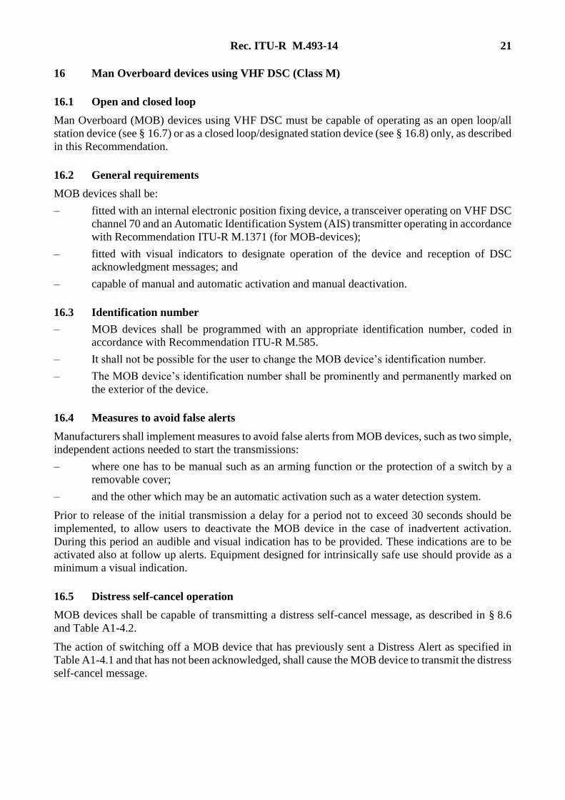
16 Man Overboard devices using VHF DSC (Class M)
16.1 Open and closed loop
Man Overboard (MOB) devices using VHF DSC must be capable of operating as an open loop/all
station device (see § 16.7) or as a closed loop/designated station device (see § 16.8) only, as described
in this Recommendation.
16.2 General requirements
MOB devices shall be:
– fitted with an internal electronic position fixing device, a transceiver operating on VHF DSC
channel 70 and an Automatic Identification System (AIS) transmitter operating in accordance
with Recommendation ITU-R M.1371 (for MOB-devices);
– fitted with visual indicators to designate operation of the device and reception of DSC
acknowledgment messages; and
– capable of manual and automatic activation and manual deactivation.
16.3 Identification number
– MOB devices shall be programmed with an appropriate identification number, coded in
accordance with Recommendation ITU-R M.585.
– It shall not be possible for the user to change the MOB device’s identification number.
– The MOB device’s identification number shall be prominently and permanently marked on
the exterior of the device.
16.4 Measures to avoid false alerts
Manufacturers shall implement measures to avoid false alerts from MOB devices, such as two simple,
independent actions needed to start the transmissions:
– where one has to be manual such as an arming function or the protection of a switch by a
removable cover;
– and the other which may be an automatic activation such as a water detection system.
Prior to release of the initial transmission a delay for a period not to exceed 30 seconds should be
implemented, to allow users to deactivate the MOB device in the case of inadvertent activation.
During this period an audible and visual indication has to be provided. These indications are to be
activated also at follow up alerts. Equipment designed for intrinsically safe use should provide as a
minimum a visual indication.
16.5 Distress self-cancel operation
MOB devices shall be capable of transmitting a distress self-cancel message, as described in § 8.6
and Table A1-4.2.
The action of switching off a MOB device that has previously sent a Distress Alert as specified in
Table A1-4.1 and that has not been acknowledged, shall cause the MOB device to transmit the distress
self-cancel message.

22 Rec. ITU-R M.493-14
16.6 Action on receipt of acknowledgment messages
If a DSC distress alert acknowledgement message, formatted in accordance with Table A1-4.2 as
response to a DSC distress alert message, or a DSC distress alert relay acknowledgment message,
formatted in accordance with Table A1-4.4 as response to a DSC distress alert relay message, is
received by the MOB device, the DSC transmitter shall be switched off. The MOB device shall
indicate reception of the acknowledgment message. The MOB device shall indicate reception of the
acknowledgment message.
16.7 Open loop MOB devices
Messages from and to open loop MOB devices using VHF DSC are defined in Tables A1-4.1 and
A1-4.2. On initial activation, the open loop MOB device shall transmit a DSC message formatted as
a distress alert as specified in Table A1-4.1. The nature of distress field shall be set to symbol 110
(man overboard) and the subsequent communications field set to symbol 126 (no information).
The position (message 2) and time (message 3) fields in the initial DSC message shall be replaced by
the digits 9 and 8 respectively, in accordance with §§ 8.2.3 and 8.2.4.
As soon as the internal electronic position fixing device is able to provide an accurate position and
time, the open loop MOB device transmits a further distress alert with the position and time from the
position fixing device automatically inserted into the message. The position expansion sequence of
Recommendation ITU-R M.821 shall be used. The AIS transmitter begins transmitting MOB
messages at this time. The messages will continue until the MOB device is manually switched off or
the battery is exhausted.
After this transmission, the DSC receiver in the open loop MOB device shall turn on and monitor the
DSC channel for acknowledgment messages for 30 minutes.
If a DSC Distress Alert Acknowledgment message is not received, the open loop MOB device shall
operate with a duty cycle of at least one message every 5 minutes for a period of 30 minutes.
The actual transmitter duty cycle shall be a randomly selected time of between 4.9 and 5.1 minutes.
After 30 minutes have elapsed without an acknowledgment message being received, the open loop
MOB device’s duty cycle should then change to 10 minutes. The actual transmitter duty cycle shall
be a randomly selected time of between 9.9 and 10.1 minutes. This will continue until an
acknowledgment message is received, the batteries are exhausted or the MOB device is switched off.
After each transmission, the DSC receiver shall turn on and monitor the DSC channel for an
acknowledgment message for 5 minutes.
16.8 Closed loop MOB devices
Messages from and to closed loop MOB devices using VHF DSC are defined in Tables A1-4.3 and
A1-4.4.
On initial activation, the closed loop MOB device shall transmit a DSC message formatted as a
distress alert relay on behalf of another ship, as specified in Table A1-4.3 with the nature of distress
set to 110 (MOB) and the subsequent communications field set to symbol 126 (no information). The
destination maritime identity may be either an individual station or a group. The position (message 2)
and time (message 3) fields in the initial DSC message shall be replaced by the digits 9 and 8
respectively, in accordance with §§ 8.2.3 and 8.2.4.
As soon as the internal electronic position fixing device is able to provide an accurate position and
time, the closed loop MOB device shall transmit a further distress alert relay on behalf of another ship
with the position and time from the position fixing device automatically inserted into the message.
The position expansion sequence of Recommendation ITU-R M.821 shall be used. The AIS

Rec. ITU-R M.493-14 23
transmitter begins transmitting MOB messages at this time. The messages will continue until the
MOB device is manually switched off or the battery is exhausted.
After this transmission, the DSC receiver in the closed loop MOB device shall turn on and monitor
the DSC channel for acknowledgment messages for 30 minutes. If a DSC distress alert relay
acknowledgment message is not received, the closed loop MOB device shall operate with a duty cycle
of at least one message every 5 minutes. The actual transmitter duty cycle shall be a randomly selected
time of between 4.9 and 5.1 minutes. If, after a 12 minute period, a DSC distress alert relay
acknowledgment message has not been received, the MOB device shall then switch from closed loop
to open loop mode by transmitting a DSC message coded as an all ships distress alert as specified in
Table A1-4.1. The nature of distress field shall be set to symbol 110 (man overboard) and the
subsequent communications field set to symbol 126 (no information). Position and time shall be
automatically inserted from the internal electronic position fixing device. After this transmission, the
DSC receiver shall turn on and monitor the DSC channel for acknowledgment messages for
5 minutes.
If a DSC distress alert acknowledgment message is not received, the MOB device shall operate with
a duty cycle of at least one distress alert every 5 minutes for a period of 30 minutes, i.e. at least one
transmission every 5 minutes for a 30 minute period. The actual transmitter duty cycle shall be a
randomly selected time of between 4.9 and 5.1 minutes. After each transmission, the DSC receiver
shall turn on and monitor the DSC channel for acknowledgment messages for 5 minutes.
After 30 minutes have elapsed without an acknowledgment message being received, the MOB
device’s duty cycle should then change to 10 minutes. The actual transmitter duty cycle shall be a
randomly selected time of between 9.9 and 10.1 minutes. This will continue until an acknowledgment
message is received, the batteries are exhausted or the MOB device is switched off. After each
transmission, the DSC receiver shall turn on and monitor the DSC channel for acknowledgment
messages for 5 minutes.

24 Rec. ITU-R M.493-14
FIGURE 1
Construction of call sequence
M.0
493
-01
Dot
pat
tern
c) T
ran
smis
sio
n se
que
nce
fo
r re
peti
tio
n of
a d
istr
ess
call
acc
ord
ing
to §
11
b)
Tra
nsm
issi
on
seq
uen
ce c
orr
esp
ondi
ng t
o F
ig.
) 1
a
Do
t pat
tern
Dot
pat
tern
Pha
sin
g
sequ
ence
Fo
rmat
sp
ecif
ier
2 i
den
tica
l
char
acte
rs
Cal
led
par
tyad
dres
s
5 ch
arac
ters
Cat
ego
ry
1 c
har
acte
r
Sel
f-id
enti
fica
tio
n
5 c
hara
cter
s
Tele
com
man
d
mes
sage
2 c
har
acte
rs
Fre
que
ncy
mes
sage
3 c
har
acte
rs
Fre
que
ncy
mes
sage
3 c
hara
cter
s
En
d o
f se
quen
ce
3 id
enti
cal
DX
ch
arac
ters
1 R
X c
har
acte
r1
char
acte
r
Err
or-c
hec
k
char
acte
r
a) T
ech
nica
l fo
rmat
of
a ty
pic
al r
outi
ne m
essa
ge
G2
G3
HI
HH
DX
DX
DX
DX
DX
DX
AA
B1
B2
B3
F3
G1
G2
G3
HI
RX
RX
RX
RX
RX
RX
RX
RX
AA
76
54
32
10
G1
F2
DX
DX
DX
DX
DX
DX
AA
B1
B2
B3
B4
B5
CD
1D
2D
3D
4D
5E
1E
2F1
F2
F3
G1
G2
G3
HI
HH
RX
RX
RX
RX
RX
RX
RX
AA
B1
B2
B3
B4
B5
67
54
32
10
CD
1D
2D
3D
4D
5E
1E
2F1
F2
F3
G1
G2
G3
HI
RX
DX
/RX
AB
CD
EF
GH
I

Rec. ITU-R M.493-14 25
FIGURE 2
Examples of a calling sequence and reply sequences for typical individual calls
M.
20
493
-0
Do
t
patt
ern
For
mat
spe
cifi
er
2 id
ent
ical
char
acte
rs
Ad
dre
ss5
char
acte
rsC
ateg
ory
1 ch
arac
ter
Sel
f-id
ent
ific
atio
n5
cha
rac
ters
Tel
eco
mm
and
and
freq
uen
cy8
ch
arac
ters
Tel
eco
mm
and
and
fre
que
ncy
8 ch
arac
ters
Ac
know
led
ge
RQ
(E
OS
)3
iden
tica
l D
X c
har
acte
rs
1 R
X c
hara
cter
Err
or-
che
ck
char
acte
r1
ch
arac
ter
Ph
asin
g
seq
uenc
e
a)
Cal
lin
g se
que
nce
b)
Rep
ly s
equ
ence
wit
h c
onf
irm
atio
n
c) R
eply
seq
uen
ce w
ith
new
pro
posa
l
d)
Rep
ly s
eque
nce
wit
h r
efu
sal
Do
t
patt
ern
Pha
sin
g se
quen
ce
For
mat
spe
cifi
er
2 i
den
tica
lch
arac
ters
Ad
dre
ss5
char
acte
rsC
ate
gory
1 c
har
acte
r
Sel
f-id
ent
ific
atio
n
5 c
hara
cte
rs
Ack
now
led
ge B
Q (
EO
S)
3 id
enti
cal
DX
cha
ract
ers
1 R
X c
har
acte
r
Err
or-
chec
k
char
acte
r1
char
acte
r
Err
or-
chec
kch
arac
ter
1 ch
arac
ter
Ack
now
ledg
e B
Q (
EO
S)
3 i
den
tica
l D
X c
har
acte
rs1
RX
cha
ract
er
Ac
know
led
ge
BQ
(E
OS
)3
iden
tica
l D
X c
har
acte
rs
1 R
X c
hara
cter
Tel
eco
mm
and
and
fre
que
ncy
8 ch
arac
ters
Tel
ecom
man
d
and
freq
uen
cy8
ch
arac
ters
Ca
teg
ory
1 c
hara
cter
Ca
teg
ory
1 c
hara
cter
Sel
f-id
ent
ific
atio
n
5 c
hara
cte
rs
Sel
f-id
enti
fica
tio
n5
ch
arac
ters
Dot
p
atte
rn
Dot
p
atte
rn
Ph
asin
g
seq
uenc
e
Pha
sin
g se
quen
ce
For
mat
spe
cifi
er
2 id
ent
ical
char
acte
rs
Fo
rmat
sp
ecif
ier
2 id
enti
cal
char
acte
rs
Ad
dre
ss
5 ch
arac
ters
Ad
dre
ss5
char
acte
rs
Err
or-
che
ckch
arac
ter
1 c
har
acte
r

26 Rec. ITU-R M.493-14
FIGURE 3
Calling sequences and reply sequences for polling and shipʼs position
M.
-3
04
930
Dot
pat
tern
Fo
rmat
sp
ecif
ier
2 i
den
tica
lch
ara
cter
s
Ad
dres
s5
ch
arac
ters
Cat
egor
y
1 c
har
acte
r
Sel
f-id
enti
fica
tion
5 c
hara
cter
sT
elec
om
man
d p
olli
ng2
ch
arac
ters
Ack
now
led
ge R
Q (
EO
S)
3 id
enti
cal
DX
ch
arac
ters
1 R
X c
hara
cter
Err
or-
chec
kch
arac
ter
1 c
hara
cter
Ph
asin
g
seq
uen
ce
a)
Cal
lin
g s
eque
nce
pol
lin
g
b)
Rep
ly s
eque
nce
to
po
llin
g
c) C
alli
ng
seq
uen
ce t
o re
que
st s
hip
’s p
osit
ion
d)
Rep
ly s
equ
ence
to
req
uest
for
sh
ip’s
pos
itio
n
Do
t pa
tte
rnP
has
ing
se
qu
ence
For
mat
spe
cifi
er2
iden
tica
l
char
acte
rs
Ad
dres
s
5 c
hara
cter
s
Cat
ego
ry
1 c
hara
cter
Sel
f-id
enti
fica
tion
5 c
hara
cter
s
Ack
now
led
ge B
Q (
EO
S)
3 id
enti
cal
DX
cha
ract
ers
1 R
X c
har
acte
r
Err
or-
chec
kch
arac
ter
1 c
hara
cter
Err
or-
chec
kch
arac
ter
1 c
hara
cter
Ack
now
ledg
e R
Q (
EO
S)
3 i
den
tica
l D
X c
har
acte
rs1
RX
cha
ract
er
Ack
now
led
ge B
Q (
EO
S)
3 id
enti
cal
DX
cha
rac
ters
1 R
X c
har
acte
r
Tel
eco
mm
and
ship
’s p
osi
tion
2 ch
arac
ters
Cat
egor
y
1 c
har
acte
r
Cat
egor
y
1 c
har
acte
r
Sel
f-id
enti
fica
tio
n
5 c
har
acte
rs
Sel
f-id
enti
fica
tion
5 ch
arac
ters
Dot
p
atte
rn
Do
t pa
tte
rn
Ph
asin
g
seq
uen
ce
Ph
asin
g
sequ
ence
Fo
rmat
sp
ecif
ier
2 id
enti
cal
char
acte
rs
For
mat
spe
cifi
er2
iden
tica
l
char
acte
rs
Add
ress
5 c
har
acte
rs
Ad
dre
ss
5 ch
arac
ters
Err
or-c
hec
k
cha
ract
er1
ch
arac
ter
Tel
eco
mm
and
poll
ing
2 ch
arac
ters
* 6c* 6c
* 6c C
oord
inat
es**
6 c
har
acte
rs
***
Tim
e
2c
Tel
eco
mm
and
ship
’s p
osi
tion
2 ch
arac
ters
*
Th
e sy
mb
ol N
o. 1
26 r
epea
ted
six
tim
es s
houl
d be
in
clu
ded
(se
e §
8.3
.2,
No
te 1
).
**
See
§ 8
.3.2
.3 (
6 ch
arac
ters
).**
*
S
ee §
8.3
.2.3
(2
char
acte
rs).

Rec. ITU-R M.493-14 27
FIGURE 4
M. 40493-0
Transmitting
Messagecomposition*
Transmitmessage
Receiving
Operation in general
No (Yes)
Yes (No)
Branching (decision)
Manual operation
Beginning or endof the procedures
This method may be used when either single channel receivers(without scanning) or multi-channel receivers are used.This method is preferable when scanning receivers are usedon DSC channels.Message composition flow chart is shown in Fig. .5
AcknowledgeBQ
AcknowledgeRQ
Scanning?
Addresserror free?
Address
corresponds to astored address?
Receive and processmessage
Store messageReceivemessage
Messagereceived error
free?
Addresscorresponds to a
stored address?
No
Yes
Yes
ReceivedECC
matches?
IndicateECC error
No
Read informationof received
message
Yes
Yes (2)
No
No
Safetyrelated?
End ofsequence
Yes
Proceduresas given in RR
No
Messagecomposition
Messagecomposition with
unableto comply
Messagecomposition with
acknowledgeBQ
Transmitmessage
End
Wait on workingfrequency/
channel
Able tocomply?
Allacceptable?
No
Yes Message composition*
Yes
Yes
Messagecomposition with
new proposal
No(1)
*
(1)
(2)
No
Yes
No
Note – This chart is informative only.
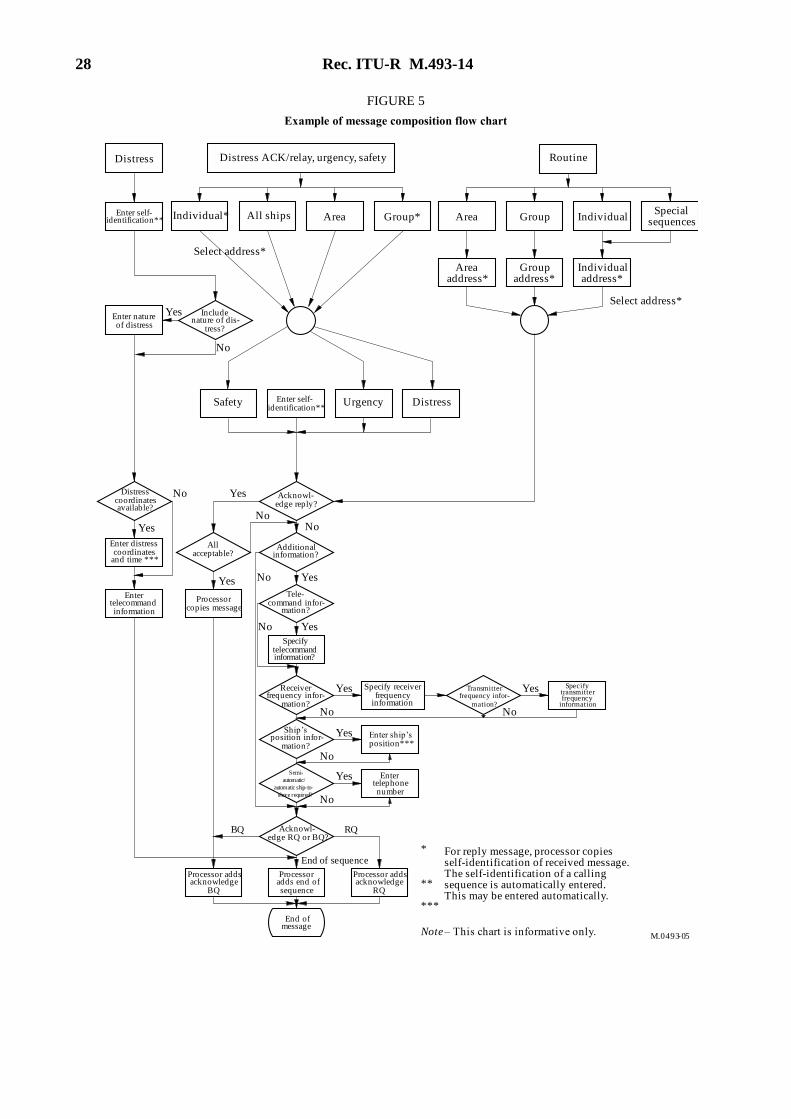
28 Rec. ITU-R M.493-14
FIGURE 5
Example of message composition flow chart
M. - 50493 0
Distress
Area GroupSpecial
sequences
Select address*
Enter self-identification**
Individualaddress*
Groupaddress*
Areaaddress*
Enter natureof distress
Includenature of dis-
tress?
Yes
No
Routine
Safety DistressUrgencyEnter self-identification**
Acknowl-edge reply?
Distresscoordinatesavailable?
Yes
No
No
Additionalinformation?
Allacceptable?
Enter distresscoordinates
and time ***
Enter telecommandinformation
Processorcopies message
No
No
No
Yes
Tele-command infor-
mation?
Yes
Specifytelecommandinformation?
Specify receiverfrequency
information
Receiverfrequency infor-
mation?
Transmitterfrequency infor-
mation?
Yes
No
Specifytransmitterfrequency
information
No
No
No
Enter ship’sposition***
Entertelephonenumber
Ship’sposition infor-
mation?
Semi-
automatic/
automatic ship-to-
shore required?
Acknowl-edge RQ or BQ?
RQBQ
End of sequence
Processor addsacknowledge
BQ
Processoradds end ofsequence
End ofmessage
Yes
Yes
Yes
Yes
Yes
For reply message, processor copiesself-identification of received message.The self-identification of a callingsequence is automatically entered.This may be entered automatically.
*
**
***
Processor addsacknowledge
RQ
IndividualIndividual* Area Group*
Distress ACK/relay, urgency, safety
All ships
Select address*
Note – This chart is informative only.
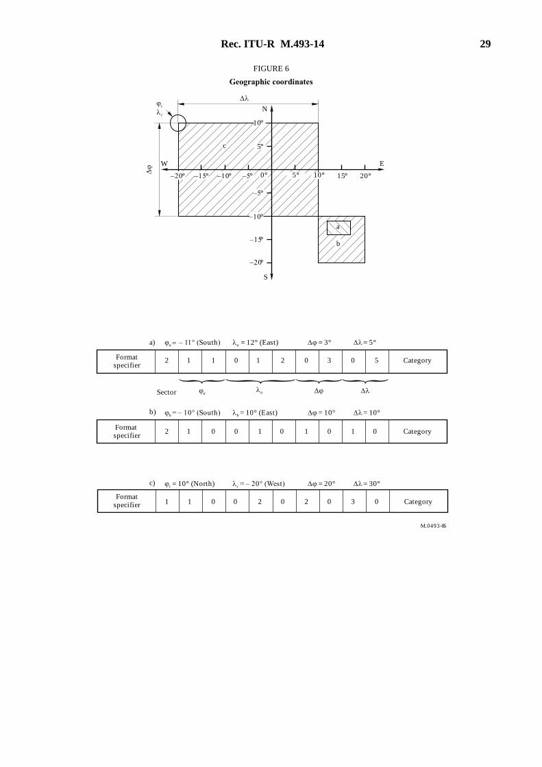
Rec. ITU-R M.493-14 29
FIGURE 6
Geographic coordinates
M. 60493-0
W
Formatspecifier
Category
Category
Category
Sector
a – 11° (South) a = 12° (East)
b = – 10° (South) b = 10° (East)
c = 10° (North) c = – 20° (West)
Formatspecifier
Formatspecifier
–15°
–20°
15° 20°
a
–15° –10° –5°
–5°
–10°
E
N
S
c
–20°
10°
5°
0° 5° 10°
b
c
c
2 1 1 0 1 2 0 3 0 5
12 0 0 1 0 1 0 1
1 1 0 0 2 0 2 0 3 0
0
a)
b)
c)
aa
= 3° = 5°
= 10° = 10°
= 20° = 30°

30 Rec. ITU-R M.493-14
Legend for Tables A1-4.1 to A1-4.11
Symbol/expression Meaning
Required
Required for backward compatibility
— Not allowed
Symbols 100-127 Symbols in accordance with Table A1-3
Area Coded in accordance with Annex 1, § 5.3
Frequency Coded in accordance with Annex 1, § 8.2.2
MMSI Coded in accordance with Annex 1, § 5.2
ID Coded in accordance with Annex 1, § 5.2
Pos1 Coded in accordance with Annex 1, § 8.1.2
Pos2 Coded in accordance with Annex 1, § 8.3.2.3
Pos3 Coded in accordance with Annex 1, § 8.3.2.3
Pos4 Coded in accordance with Annex 1, § 8.3.2.3
Pos5 Coded in accordance with Recommendation ITU-R M.821
UTC Coded in accordance with Annex 1, § 8.1.3
n/a This field is not included in this call
ECC Coded in accordance with Annex 1, § 10.2
EOS Coded in accordance with Annex 1, § 9
expan1 Expansion sequence 1
expan2 Expansion sequence 2
expan3 Expansion sequence 3
Does not apply
NOTE 1 – For Class A and B all functions are identical for VHF and MF. HF does not
apply to Class B.

Rec. ITU-R M.493-14 31
TABLE A1-4.1
Distress alerts
Frequency
band Type
Applicable to Technical format of call sequence
Ship
station
Class
A/B
Ship
station
Class D
Ship
station
Class E
Hand-
held
Class H
MOB
Device
Class M
Open loop Coast
station Format
specifier
(2 identical)
Self-
ID
(5)
Message
EOS
(1)
ECC
(1)
EOS
(2 identical)
Rec. ITU-R
M.821
expansion
sequence*
(9)
1 2 3 4
Nature of
distress (1)
Distress
coordinates
(5)
Time
(2)
Subsequent
communications
(1) Tx Rx Tx Rx Tx Rx Tx Rx Tx Rx Tx Rx
VHF Distress (RT) — —
112 Self-ID
100 to 110 Pos1 UTC 100** 127 ECC 127 expan1
Distress (EPIRB) — — —
— — — 112
Self-ID
112 Pos1 UTC 126 127 ECC 127 expan1
MF/HF Distress (RT)
— 112
Self-ID
100 to 110 Pos1 UTC 109 127 ECC 127 expan1
Distress (FEC) —
— 112
Self-ID
100 to 110 Pos1 UTC 113 127 ECC 127 expan1
* Expansion sequence see Table A1-4.11
** For class M, this field is set to 126

32 Rec. ITU-R M.493-14
TABLE A1-4.2
Distress acknowledgements
Frequency
band Type
Applicable to Technical format of call sequence
Ship
station
Class A/B
Ship
station
Class D
Ship
station
Class E
Hand-
held
Class H
MOB
Device
Class M
open loop
Coast
station Format
specifier
(2 iden-
tical)
Cate-
gory
(1)
Self-
ID
(5)
Tele-
comman
d
(1)
Message
EOS
(1)
ECC
(1)
EOS
(2 iden-
tical)
Rec. ITU-
R M.821
expansion
sequence*
(9)
0 1 2 3 4
Distress
ID
(5)
Nature
of
distress
(1)
Distress
coordi-
nates
(5)
Time
(2)
Subse-
quent
commu-
nications
(1)
Tx Rx Tx Rx Tx Rx Tx Rx Tx Rx Tx Rx
VHF Distress
acknowl-
edgement (RT)
— — — 116 112 Self-ID 110 Distress
ID 100 - 110 Pos1 UTC 100** 127 ECC 127 expan1
Distress
acknowl-
edgement
(EPIRB)
— — — — 116 112 Self-ID 110 Distress
ID 112 Pos1 UTC 126 127 ECC 127 expan1
Distress
self-cancel
— — 116 112 Self-ID 110 Self-ID 100 - 110 Pos1 UTC 100* 127 ECC 127 expan1
* Expansion sequence see Table A1-4.11
** For class M, this field is set to 126

Rec. ITU-R M.493-14 33
TABLE A1-4.2 (end)
Distress acknowledgements
Frequenc
y
band Type
Applicable to Technical format of call sequence
Message
Ship
station
Class A/B
Ship
station
Class D
Ship
station
Class E
Hand-
held
Class H
MOB
Device
Class M
open loopCoast
station
0 1 2 3 4
Format
specifier
(2 iden-
tical)
Categor
y
(1)
Self-
ID
(5)
Tele-
comman
d
(1)
Distress
ID
(5)
Nature
of
distress
(1)
Distress
coordi-
nates
(5)
Time
(2)
Subse-
quent
commu-
nications
(1)
EOS
(1)
ECC
(1)
EOS
(2 iden-
tical)
Rec. ITU-
R M.821
expansion
sequence*
(9) TxRx Tx Rx Tx Rx Tx Rx Tx Rx Tx Rx
MF Distress
acknowl-
edgement (RT)
— 116 112 Self-ID 110 Distress
ID 100 - 110 Pos1 UTC 109 127 ECC 127 expan1
Distress
acknowl-edgement
(FEC)
— 116 112 Self-ID 110 Distress
ID 100 -110 Pos1 UTC 113 127 ECC 127 expan1
Distress
self-cancel
— 116 112 Self-ID 110 Self-ID 100 - 110 Pos1 UTC 109 127 ECC 127 expan1
HF Distress
acknowl-
edgement (RT)
— — 116 112 Self-ID 110 Distress
ID 100 - 110 Pos1 UTC 109 127 ECC 127 expan1
Distress
acknowl-edgement
(FEC)
— — 116 112 Self-ID 110 Distress
ID 100 - 110 Pos1 UTC 113 127 ECC 127 expan1
Distress
self- cancel
— 116 112 Self-ID 110 Self-ID 100 to
110 Pos1 UTC 109 127 ECC 127 expan1
( The message should match the received distress alert information,
except for manually generated distress acknowledgements by coast
stations.
* Expansion sequence see Table A1-4.11
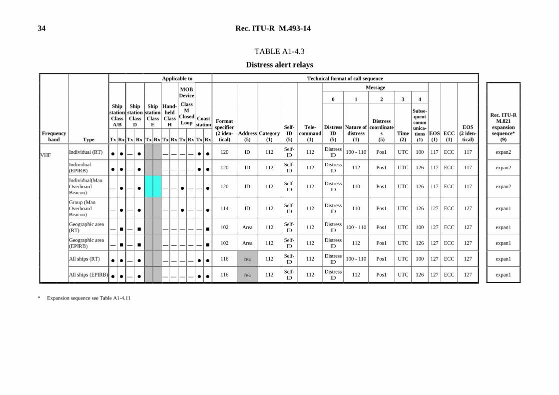
34 Rec. ITU-R M.493-14
TABLE A1-4.3
Distress alert relays
Type
Applicable to Technical format of call sequence
Ship
station
Class
A/B
Ship
station
Class
D
Ship
station
Class
E
Hand-
held
Class
H
MOB
Device
Class
M
Closed
Loop Coast
station Format
specifier
(2 iden-
tical)
Address
(5)
Category
(1)
Self-
ID
(5)
Tele-
command
(1)
Message
EOS
(1)
ECC
(1)
EOS
(2 iden-
tical)
Rec. ITU-R
M.821
expansion
sequence*
(9)
0 1 2 3 4
Distress
ID
(5)
Nature of
distress
(1)
Distress
coordinate
s
(5)
Time
(2)
Subse-
quent
comm
unica-
tions
(1)
Frequency
band Tx Rx Tx Rx Tx Rx Tx Rx Tx Rx Tx Rx
VHF Individual (RT)
— ————120 ID 112
Self-ID
112 Distress
ID 100 - 110 Pos1 UTC 100 117 ECC 117 expan2
Individual (EPIRB) — ————
120 ID 112 Self-ID
112 Distress
ID 112 Pos1 UTC 126 117 ECC 117 expan2
Individual(Man
Overboard Beacon)
—— — — — —120 ID 112
Self-ID
112 Distress
ID 110 Pos1 UTC 126 117 ECC 117 expan2
Group (Man
Overboard Beacon)
—— — — — —114 ID 112
Self-ID
112 Distress
ID 110 Pos1 UTC 126 127 ECC 127 expan1
Geographic area
(RT) —— —————102 Area 112
Self-
ID 112
Distress
ID 100 - 110 Pos1 UTC 100 127 ECC 127 expan1
Geographic area (EPIRB) —— —————
102 Area 112 Self-ID
112 Distress
ID 112 Pos1 UTC 126 127 ECC 127 expan1
All ships (RT)
— ————116 n/a 112
Self-ID
112 Distress
ID 100 - 110 Pos1 UTC 100 127 ECC 127 expan1
All ships (EPIRB)
— ————116 n/a 112
Self-
ID 112
Distress
ID 112 Pos1 UTC 126 127 ECC 127 expan1
* Expansion sequence see Table A1-4.11

Rec. ITU-R M.493-14 35
TABLE A1-4.3 (end)
Distress alert relays
Type
Applicable to Technical format of call sequence
Ship
station
Class
A/B
Ship
station
Class
D
Ship
station
Class
E
Hand-
held
Class
H
MOB
Device
Class
M
Open
and
Closed
Loop Coast
station
Format
specifier
(2 iden-
tical)
Address
(5)
Category
(1)
Self-
ID
(5)
Tele-
command
(1)
Message
EOS
(1)
ECC
(1)
EOS
(2 iden-
tical)
Rec. ITU-R
M.821
expansion
sequence*
(9)
0 1 2 3 4
Frequency
band
Distress
ID
(5)
Nature of
distress
(1)
Distress
coordinates
(5)
Time
(2)
Subse-
quent
com-
muni-
cations
(1)
Tx Rx Tx Rx Tx Rx Tx Rx Tx Rx Tx Rx
MF/HF Individual (RT)
— 120 MMSI 112
Self-ID
112 Distress
ID 100 - 110 Pos1 UTC 109 117 ECC 117 expan2
Individual (FEC) —
120 MMSI 112 Self-ID
112 Distress
ID 100 - 110 Pos1 UTC 113 117 ECC 117 expan2
Geographic area
(RT) — 102 Zone 112
Self-
ID 112
Distress
ID 100 - 110 Pos1 UTC 109 127 ECC 127 expan1
Geographic area (FEC) —
102 Zone 112 Self-ID
112 Distress
ID 100 - 110 Pos1 UTC 113 127 ECC 127 expan1
All ships (RT) — — — 116 n/a 112 Self- ID
112 Distress
ID 100 - 110 Pos1 UTC 109 127 ECC 127
expan1
All ships (FEC) — — — 116 n/a 112 Self- ID
112 Distress
ID 100 - 110 Pos1 UTC 113 127 ECC 127
expan1
The message should match the received distress
alert information, except for manually generated distress alert relays observed or notified by non-
DSC means.
* Expansion sequence see Table A1-4.11

36 Rec. ITU-R M.493-14
TABLE A1-4.4
Distress alert relay acknowledgements
Frequency
band Type
Applicable to Technical format of call sequence
Ship
station
Class
A/B
Ship
station
Class
D
Ship
station
Class
E
Hand-
held
Class
H
MOB
Device
Class
M
Closed
Loop
Coast
station Format
specifier
(2 iden-
tical)
Address
(5)
Category
(1)
Self-
ID
(5)
Tele
command
(1)
Message
EOS
(1)
ECC
(1)
EOS
(2 iden-
tical)
Rec. ITU-R
M.821
expansion
sequence*
(9)
0 1 2 3 4
Distress
ID
(5)
Nature of
distress
(1)
Distress
coordinates
(5)
Time
(2)
Subse-
quent
commu-
nication
s
(1) Tx Rx Tx Rx Tx Rx Tx Rx Tx Rx Tx Rx
VHF Individual (RT) — ———— 120 ID 112 Self-ID
112 Distress
ID 100 - 110 Pos1 UTC 100 122 ECC 122 expan3
DROBOSE to a
Group (RT) — — — 114 ID 112
Self-
ID 112
Distress
ID 110 Pos1 UTC 126 122 ECC 122 expan3
Individual (EPIRB)
— ———— 120 ID 112 Self-ID
112 Distress
ID 112 Pos1 UTC 126 122 ECC 122 expan3
All ships (RT) —— ———— 116 n/a 112
Self-ID
112 Distress
ID 100 - 110 Pos1 UTC 100 122 ECC 122 expan3
All ships (EPIRB) —— ———— 116 n/a 112
Self-ID
112 Distress
ID 112 Pos1 UTC 126 122 ECC 122 expan3
MF/HF Individual (RT) 120 ID 112
Self-ID
112 Distress
ID 100 - 110 Pos1 UTC 109 122 ECC 122 expan3
Individual (FEC) — 120 ID 112
Self-ID
112 Distress
ID 100 - 110 Pos1 UTC 113 122 ECC 122 expan3
All ships (RT) — — 116 n/a 112
Self-ID
112 Distress
ID 100 - 110 Pos1 UTC 109 122 ECC 122 expan3
All ships (FEC) — — 116 n/a 112
Self-
ID 112
Distress
ID 100 - 110 Pos1 UTC 113 122 ECC 122 expan3
The message should match the received distress alert
relay call information.
* Expansion sequence see Table A1-4.11

Rec. ITU-R M.493-14 37
TABLE A1-4.5
Urgency and safety calls – All ships
Frequency
band Type
Applicable to Technical format of call sequence
Ship
station
Class A/B
Ship
station
Class D
Ship
station
Class E
Hand-held
Class H
MOB
Device
Class M
Open and
Closed Loop
Coast
station Format
specifier
(2 identical)
Category
(1)
Self-ID
(5)
Message
EOS
(1)
ECC
(1)
EOS
(2
identical)
1 2
1st tele-
command
(1)
2nd tele-
command
(1)
Frequency
(6) or (8) Tx Rx Tx Rx Tx Rx Tx Rx Tx Rx Tx Rx
VHF All modes RT — — — 116 108 or 110 Self-ID 100 126 Frequency 127 ECC 127
Duplex RT(1) — — — — — — 116 108 or 110 Self-ID 101 126 Frequency 127 ECC 127
Medical transports — — — — — — — 116 110 Self-ID 100 111 Frequency 127 ECC 127
Ships and aircraft
(Res. 18) — — — — — — — 116 110 Self-ID 100 110 Frequency 127 ECC 127
MF/HF J3E RT — — — — — 116 108 or 110 Self-ID 109 126 Frequency 127 ECC 127
F1B FEC — — — — — 116 108 or 110 Self-ID 113 126 Frequency 127 ECC 127
(1) See § 8.3.1

38 Rec. ITU-R M.493-14
TABLE A1-4.6
Urgency and safety – Geographic area calls
Frequency
band Type
Applicable to Technical format of call sequence
Ship
station
Class
A/B
Ship
station
Class D
Ship
station
Class E
Hand-
held
Class H
MOB
Device
Class M
Open and
Closed
Loop
Coast
station
Format
specifier
(2
identical)
Address
(5)
Category
(1)
Self-ID
(5)
Message
EOS
(1)
ECC
(1)
EOS
(2 identical)
1 2
1st tele-
command
(1)
2nd tele-
command
(1)
Frequency
(6) or (8) Tx Rx Tx Rx Tx Rx Tx Rx Tx Rx Tx Rx
MF/HF J3E (RT) 102 Area 108 or 110 Self-ID 109 126 Frequency 127 ECC 127
F1B (FEC) —— 102 Area 108 or 110 Self-ID 113 126 Frequency 127 ECC 127
Medical transports —— — 102 Area 110 Self-ID 109 or 113 111 Frequency 127 ECC 127
Ships and aircraft (Res. 18) —— — 102 Area 110 Self-ID 109 or 113 110 Frequency 127 ECC 127

Rec. ITU-R M.493-14 39
TABLE A1-4.7
Urgency and safety – Individual calls and their acknowledgements
Type
Applicable to Technical format of call sequence
Rec. ITU-R
M.821
expansion
sequence*
(9)
Ship
station
Class
A/B
Ship
station
Class
D
Ship
station
Class E
Hand-
held
Class
H
MOB
Device
Class M
Open
and
Closed
Loop
Coast
station
Format
specifier
(2
identical)
Address
(5)
Category
(1)
Self-ID
(5)
Message
EOS
(1)
ECC
(1)
EOS
(2 identical)
1 2 3
Frequency
band
1st tele-
command
(1)
2nd tele-
command
(1)
Frequency
or pos
number
(6) or (8)
Time
(2)
Tx Rx Tx Rx Tx Rx Tx Rx Tx Rx Tx Rx
VHF All modes RT — ———— 120 ID 108 or
110 Self-ID 100 126 Frequency n/a 117 ECC 117
—
Duplex RT(1) ——— ——— — — 120 ID
108 or 110
Self-ID 101 126 Frequency n/a 117 ECC 117 —
RT
acknowledgement — ——— 120 ID
108 or
110 Self-ID 100 126 Frequency n/a 122 ECC 122
—
Unable to comply acknowledgement
— ——— 120 ID 108 or
110 Self-ID 104 100 - 109 Frequency n/a 122 ECC 122
—
Position request — ——— — 120 ID 108 Self-ID 121 126 Pos3 n/a 117 ECC 117 —
Position acknowledgement
— —— — — 120 ID 108 Self-ID 121 126 Pos4 UTC 122 ECC 122
expan3
Test —— 120 ID 108 Self-ID 118 126 126 n/a 117 ECC 117 —
Test
acknowledgement —— 120 ID 108 Self-ID 118 126 126 n/a 122 ECC 122
—
* Expansion sequence see Table A1-4.11

40 Rec. ITU-R M.493-14
TABLE A1-4.7 (end)
Urgency and safety – Individual calls and their acknowledgements
Type
Applicable to Technical format of call sequence
Rec. ITU-R
M.821
expansion
sequence*
(9)
Ship
station
Class
A/B
Ship
station
Class
D
Ship
station
Class
E
Hand-
held
Class
H
MOB
Device
Class M
Open and
Closed
Loop
Coast
station
Format
specifier
(2
identical)
Address
(5)
Categor
y
(1)
Self-ID
(5)
Message
EOS
(1)
ECC
(1)
1 2 3
Frequency
band 1st tele-
command
(1)
2nd tele-
command
(1)
Frequency or
pos number
(6) or (8)
Time
(2)
EOS
(2
identical)
Tx Rx Tx Rx Tx Rx Tx Rx Tx Rx Tx Rx
MF/HF J3E RT
—
120 ID
108 or 110
Self-ID 109 126 Frequency n/a 117 ECC 117 —
J3E RT with pos number — ——
— 120 ID
108 or 110
Self-ID 109 126 Pos2 n/a 117 ECC 117 —
J3E RT acknowledgement —
120 ID 108 or
110 Self-ID 109 126 Frequency n/a 122 ECC 122
—
F1B FEC or ARQ ——
120 ID 108 or
110 Self-ID 113 or 115 126 Frequency n/a 117 ECC 117
—
F1B FEC or ARQ with pos number — ——
— 120 ID
108 or 110
Self-ID 113 or 115 126 Pos2 n/a 117 ECC 117 —
F1B FEC or ARQ acknowledgement ——
120 ID 108 or
110 Self-ID 113 or 115 126 Frequency n/a 122 ECC 122
—
Unable to comply acknowledgement —
120 ID 108 or
110 Self-ID 104 100 - 109 Frequency n/a 122 ECC 122
—
Position request — —
120 ID 108 Self-ID 121 126 Pos3 n/a 117 ECC 117 —
Position
acknowledgement — —
120 ID 108 Self-ID 121 126 Pos4 UTC 122 ECC 122
expan3
Test
120 ID 108 Self-ID 118 126 126 n/a 117 ECC 117 —
Test acknowledgement
120 ID 108 Self-ID 118 126 126 n/a 122 ECC 122 —
(1) See § 8.3.1
* Expansion sequence see Table A1-4.11

Rec. ITU-R M.493-14 41
TABLE A1-4.8
Routine group calls
Frequency
band Type
Applicable to Technical format of call sequence
Ship
station
Class
A/B
Ship
station
Class
D
Ship
station
Class
E
Hand-
held
Class
H
MOB
Device
Class M
Open and
Closed
Loop
Coast
station Format
specifier
(2 identical)
Address
(5)
Category
(1)
Self-ID
(5)
Message
EOS
(1)
ECC
(1)
EOS
(2 identical)
1 2
1st tele-
command
(1)
2nd tele-
command
(1)
Frequency
(6) Tx Rx Tx Rx Tx Rx Tx Rx Tx Rx Tx Rx
VHF All mode RT — — 114 MMSI 100 Self-ID 100 126 Frequency 127 ECC 127
Duplex RT(1) ——— —— — — — 114 MMSI 100 Self-ID 101 126 Frequency 127 ECC 127
MF/HF J3E RT 114 MMSI 100 Self-ID 109 126 Frequency 127 ECC 127
F1B FEC —— 114 MMSI 100 Self-ID 113 126 Frequency 127 ECC 127
(1) See § 8.3.1.
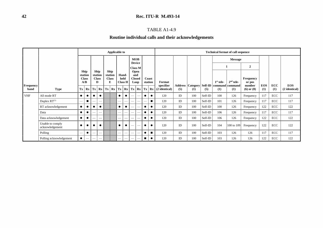
42 Rec. ITU-R M.493-14
TABLE A1-4.9
Routine individual calls and their acknowledgements
Frequency
band Type
Applicable to Technical format of call sequence
Ship
station
Class
A/B
Ship
station
Class
D
Ship
station
Class
E
Hand-
held
Class H
MOB
Device
Class M
Open
and
Closed
Loop
Coast
station Format
specifier
(2 identical)
Address
(5)
Category
(1)
Self-ID
(5)
Message
EOS
(1)
ECC
(1)
EOS
(2 identical)
1 2
1st tele-
command
(1)
2nd tele-
command
(1)
Frequency
or pos
number
(6) or (8) Tx Rx Tx Rx Tx Rx Tx Rx Tx Rx Tx Rx
VHF All mode RT —— 120 ID 100 Self-ID 100 126 Frequency 117 ECC 117
Duplex RT(1) — — — — — — — — 120 ID 100 Self-ID 101 126 Frequency 117 ECC 117
RT acknowledgement —— 120 ID 100 Self-ID 100 126 Frequency 122 ECC 122
Data —— ———— 120 ID 100 Self-ID 106 126 Frequency 117 ECC 117
Data acknowledgement —— ———— 120 ID 100 Self-ID 106 126 Frequency 122 ECC 122
Unable to comply acknowledgement
—— 120 ID 100 Self-ID 104 100 to 109 Frequency 122 ECC 122
Polling ——— ———— 120 ID 100 Self-ID 103 126 126 117 ECC 117
Polling acknowledgement ——— ———— 120 ID 100 Self-ID 103 126 126 122 ECC 122

Rec. ITU-R M.493-14 43
TABLE A1-4.9 (end)
Routine individual calls and their acknowledgements
Frequency
band Type
Applicable to Technical format of call sequence
Ship
station
Class
A/B
Ship
station
Class
D
Ship
station
Class
E
Hand-
held
Class H
MOB
Device
Class M
Open
and
Closed
Loop
Coast
station Format
specifier
(2 identical)
Address
(5)
Category
(1)
Self-ID
(5)
Message
EOS
(1)
ECC
(1)
EOS
(2 identical)
1 2
1st tele-
command
(1)
2nd tele-
command
(1)
Frequency
or pos
number
(6) or (8) Tx Rx Tx Rx Tx Rx Tx Rx Tx Rx Tx Rx
MF/HF J3E RT 120 ID 100 Self-ID 109 126 Frequency 117 ECC 117
J3E RT with pos number — — — 120 ID 100 Self-ID 109 126 Pos2 117 ECC 117
J3E RT acknowledgement 120 ID 100 Self-ID 109 126 Frequency 122 ECC 122
F1B FEC, ARQ or data —— 120 ID 100 Self-ID 113, 115, 106 126 Frequency 117 ECC 117
FEC, ARQ or data with pos
number — —— — 120 ID 100 Self-ID 113, 115, 106 126 Pos2 117 ECC 117
F1B FEC, ARQ or data acknowledgement
—— 120 ID 100 Self-ID 113, 115, 106 126 Frequency 122 ECC 122
Unable to comply acknowledgement
—— 120 ID 100 Self-ID 104 100 - 109 Frequency 122 ECC 122
Polling — —— 120 ID 100 Self-ID 103 126 126 117 ECC 117
Polling acknowledgement — —— 120 ID 100 Self-ID 103 126 126 122 ECC 122
(1) Seel § 8.3.1.
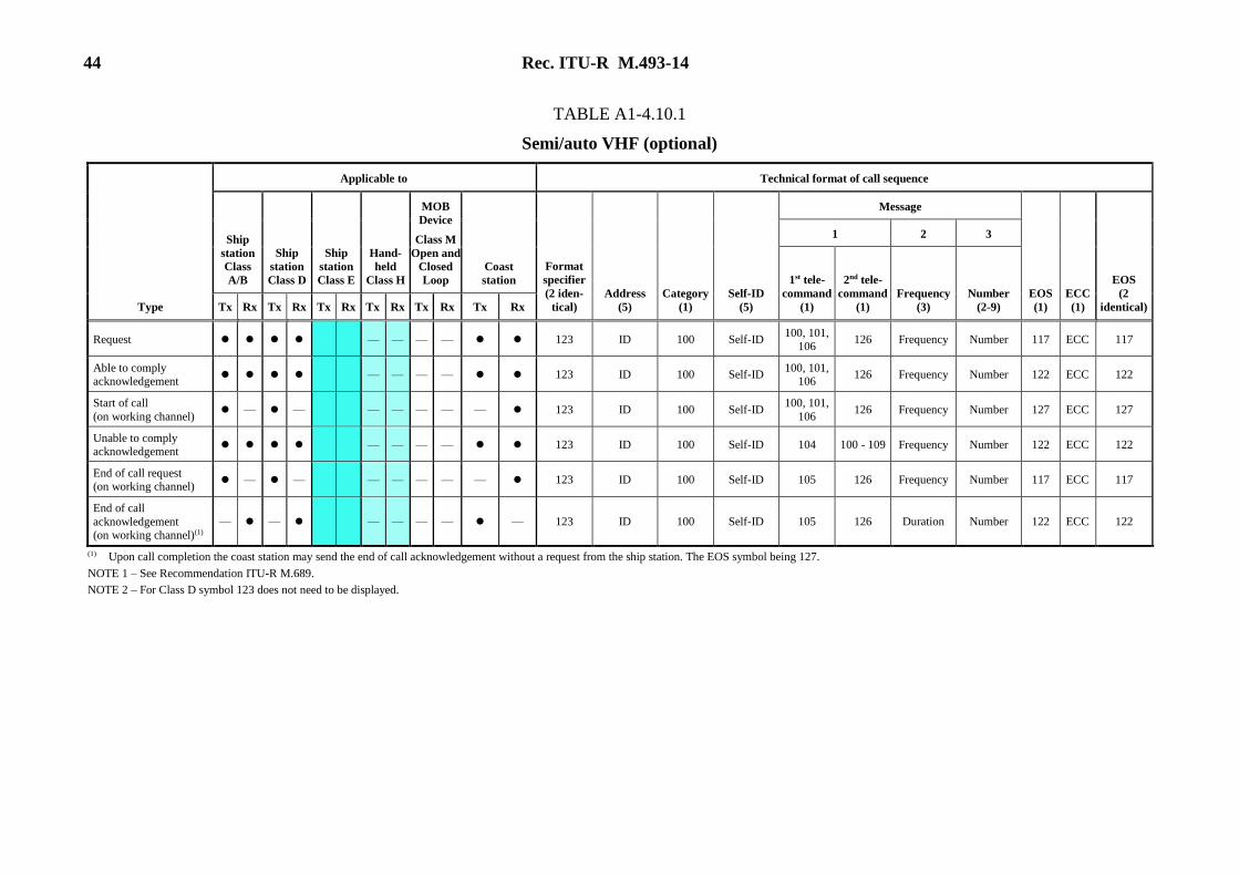
44 Rec. ITU-R M.493-14
TABLE A1-4.10.1
Semi/auto VHF (optional)
Type
Applicable to Technical format of call sequence
Ship
station
Class
A/B
Ship
station
Class D
Ship
station
Class E
Hand-
held
Class H
MOB
Device
Class M
Open and
Closed
Loop
Coast
station
Format
specifier
(2 iden-
tical)
Address
(5)
Category
(1)
Self-ID
(5)
Message
EOS
(1)
ECC
(1)
EOS
(2
identical)
1 2 3
1st tele-
command
(1)
2nd tele-
command
(1)
Frequency
(3)
Number
(2-9) Tx Rx Tx Rx Tx Rx Tx Rx Tx Rx Tx Rx
Request ———— 123 ID 100 Self-ID 100, 101,
106 126 Frequency Number 117 ECC 117
Able to comply acknowledgement
———— 123 ID 100 Self-ID 100, 101,
106 126 Frequency Number 122 ECC 122
Start of call
(on working channel) —— ——— — — 123 ID 100 Self-ID
100, 101,
106 126 Frequency Number 127 ECC 127
Unable to comply acknowledgement
———— 123 ID 100 Self-ID 104 100 - 109 Frequency Number 122 ECC 122
End of call request (on working channel)
—— ——— — — 123 ID 100 Self-ID 105 126 Frequency Number 117 ECC 117
End of call
acknowledgement (on working channel)(1)
—— ———— — 123 ID 100 Self-ID 105 126 Duration Number 122 ECC 122
(1) Upon call completion the coast station may send the end of call acknowledgement without a request from the ship station. The EOS symbol being 127. NOTE 1 – See Recommendation ITU-R M.689.
NOTE 2 – For Class D symbol 123 does not need to be displayed.

Rec. ITU-R M.493-14 45
TABLE A1-4.10.2
Semi/auto MF/HF (optional)
Type
J3E RT or F1B FEC/ARQ
Applicable to Technical format of call sequence
Ship
station
Class
A/B
Ship
station
Class
D
Ship
station
Class
E
Hand-
held
Class
H
MOB
Device
Class
M
Open
and
Closed
Loop
Coast
station
Format
specifier
(2 iden-
tical)
Address
(5)
Category
(1)
Self-ID
(5)
Message
EOS
(1)
ECC
(1)
EOS
(2 iden-
tical)
1 2 3
1st tele
command
(1)
2nd tele-
command
(1)
Frequency
or pos
number
(6) or (8)
Number
(2-9) Tx Rx Tx Rx Tx Rx Tx Rx Tx Rx Tx Rx
Request coast station — — — 123 ID 100 Self-ID 109, 113, 115 126 Frequency Number 117 ECC 117
Request ship station — — — 123 ID 100 Self-ID 109, 113, 115 126 126 or Pos2 Number 117 ECC 117
Able to comply acknowledgement 123 ID 100 Self-ID 109, 113, 115 126 Frequency Number 122 ECC 122
Signal strength test by ship (on working channel)(1)
— —
— 123 ID 100 Self-ID 109, 113, 115 126 Frequency Number 117 ECC 117
Coast station acknowledgement with new
working frequency(1) — —
— 123 ID 100 Self-ID 109, 113, 115 126
New
frequency Number 122 ECC 122
Call start: Coast station acknowledgement with same working frequency(1)
— —
— 123 ID 100 Self-ID 109, 113, 115 126 Same
frequency Number 122 ECC 122
Unable to comply 123 ID 100 Self-ID 104 100 - 109 Frequency Number 122 ECC 122
End of call request (on working channel) — — — 123 ID 100 Self-ID 105 126 Frequency Number 117 ECC 117
End of call acknowledgement (on working
channel)(2) — —
— 123 ID 100 Self-ID 105 126 Duration Number 122 ECC 122
(1) This call involves signal strength testing. The ship requests call by sending the coast station its position. Once the ship or coast station is able to comply the ship station sends test DSCs on the working frequency. If the coast
station acknowledges with a new working frequency, the ship station sends a test DSC on the new frequency. When the coast station acknowledges with an unchanged frequency, the subsequent communication may begin. (2) Upon call completion the coast station may send the end of call acknowledgement without a request from the ship station. The EOS symbol being 127.
NOTE 1 – See Recommendation ITU-R M.1082.
NOTE 2 – For Class E symbol 123 does not need to be displayed.

46 Rec. ITU-R M.493-14
TABLE A1-4.11
Expansion sequences
Rec. ITU-R M.821 expansion sequence
Type
Expansion data
specifier
(1)
Enhanced
position
resolution
(4)
EOS
(1)
ECC
(1)
EOS
(2 identical)
expan1 100 Pos5 127 ECC 127
expan2 100 Pos5 117 ECC 117
expan3 100 Pos5 122 ECC 122
TABLE A1-5
Frequency or channel information
Frequency
0
1 2
X
X X
X
X X
X
X X
X
X X
X
X X
(N/A)
The frequency in multiples of 100 Hz as indicated by the
figures for the digits HM, TM, M, H, T, U. This should be
used for MF, HF equipment except when using seven-digit
frequencies.
Channels 3 X X X X X (N/A)
The HF/MF working channel number indicated by the values
of the digits TM, M, H, T and U. This should be used for backward compatibility in receive only mode.
Frequency
4
4
4
0
1
2
X
X
X
X
X
X
X
X
X
X
X
X
X
X
X
X
X
X
The frequency in multiples of 10 Hz as indicated by the
figures for the digits TM, M, H, T, U, T1 and U1. This should
be used for MF, HF equipment when using seven-digit frequencies.
Channels
8 X X X X X (N/A) Only used for Recommendation ITU-R M.586 equipment.
9 0 X (1)
X X X (N/A) The VHF working channel number indicated by the values of
the digits M, H, T and U.
HM TM M H T U T1 U1
Character
3
Character
2
Character
1(2)
Character
0
(1) If the M digit is 1 this indicates that the ship stations transmitting frequency is being used as a simplex channel frequency for
both ship and coast stations. If the M digit is 2 this indicates that the coast stations transmitting frequency is being used as a
simplex channel frequency for both ship and coast stations. If the M digit is 0, this indicates the frequency being used is in
accordance with RR Appendix 18 for both single and two frequency channels.
(2) Character 1 is the last character transmitted except when using seven-digit frequencies.
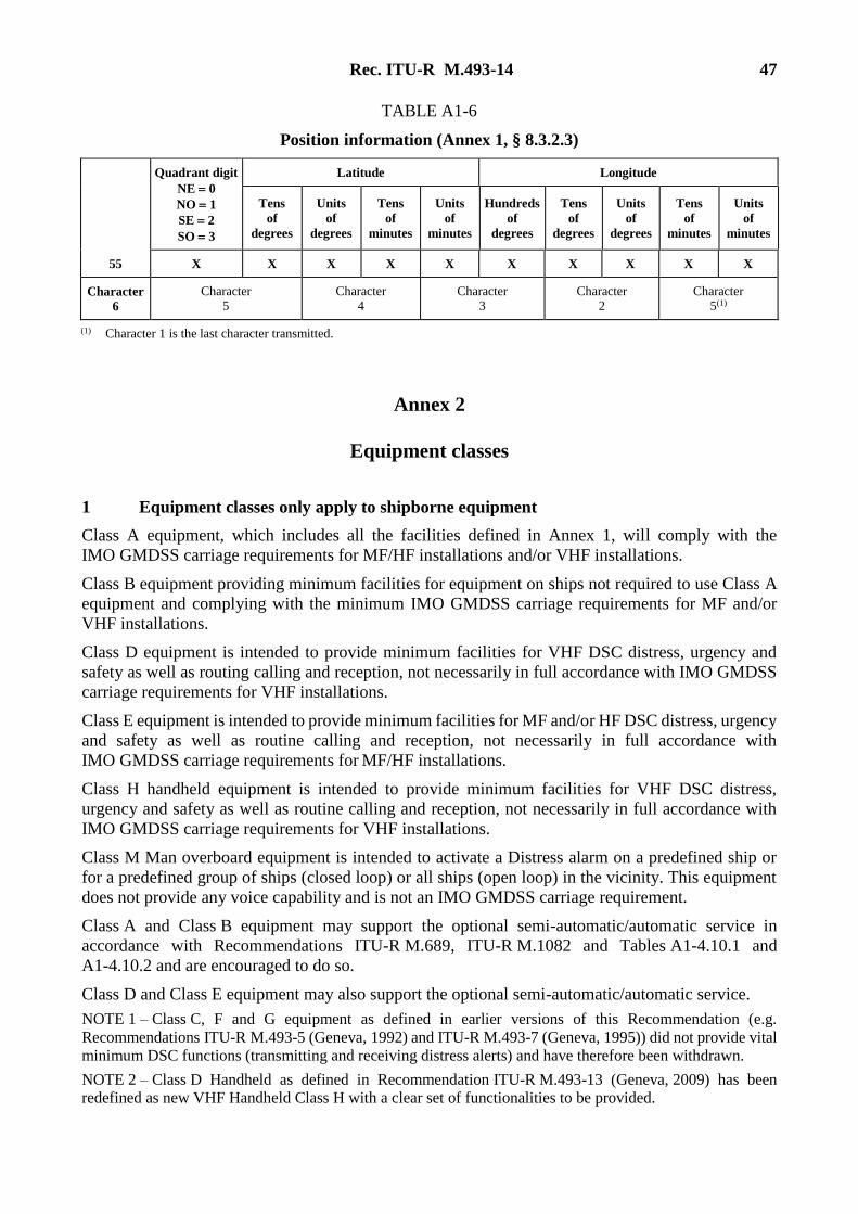
Rec. ITU-R M.493-14 47
TABLE A1-6
Position information (Annex 1, § 8.3.2.3)
Quadrant digit
NE 0
NO 1
SE 2
SO 3
Latitude Longitude
Tens
of
degrees
Units
of
degrees
Tens
of
minutes
Units
of
minutes
Hundreds
of
degrees
Tens
of
degrees
Units
of
degrees
Tens
of
minutes
Units
of
minutes
55 X X X X X X X X X X
Character
6
Character 5
Character 4
Character 3
Character 2
Character 5(1)
(1) Character 1 is the last character transmitted.
Annex 2
Equipment classes
1 Equipment classes only apply to shipborne equipment
Class A equipment, which includes all the facilities defined in Annex 1, will comply with the
IMO GMDSS carriage requirements for MF/HF installations and/or VHF installations.
Class B equipment providing minimum facilities for equipment on ships not required to use Class A
equipment and complying with the minimum IMO GMDSS carriage requirements for MF and/or
VHF installations.
Class D equipment is intended to provide minimum facilities for VHF DSC distress, urgency and
safety as well as routing calling and reception, not necessarily in full accordance with IMO GMDSS
carriage requirements for VHF installations.
Class E equipment is intended to provide minimum facilities for MF and/or HF DSC distress, urgency
and safety as well as routine calling and reception, not necessarily in full accordance with
IMO GMDSS carriage requirements for MF/HF installations.
Class H handheld equipment is intended to provide minimum facilities for VHF DSC distress,
urgency and safety as well as routine calling and reception, not necessarily in full accordance with
IMO GMDSS carriage requirements for VHF installations.
Class M Man overboard equipment is intended to activate a Distress alarm on a predefined ship or
for a predefined group of ships (closed loop) or all ships (open loop) in the vicinity. This equipment
does not provide any voice capability and is not an IMO GMDSS carriage requirement.
Class A and Class B equipment may support the optional semi-automatic/automatic service in
accordance with Recommendations ITU-R M.689, ITU-R M.1082 and Tables A1-4.10.1 and
A1-4.10.2 and are encouraged to do so.
Class D and Class E equipment may also support the optional semi-automatic/automatic service.
NOTE 1 – Class C, F and G equipment as defined in earlier versions of this Recommendation (e.g.
Recommendations ITU-R M.493-5 (Geneva, 1992) and ITU-R M.493-7 (Geneva, 1995)) did not provide vital
minimum DSC functions (transmitting and receiving distress alerts) and have therefore been withdrawn.
NOTE 2 – Class D Handheld as defined in Recommendation ITU-R M.493-13 (Geneva, 2009) has been
redefined as new VHF Handheld Class H with a clear set of functionalities to be provided.

48 Rec. ITU-R M.493-14
Annex 3
User interface for simplified operation of shipborne equipment
1 General
The user interface for operation of the DSC equipment should be so designed that it will be easy for
the operator onboard the ship to operate the equipment and to compose and initiate the types of DSC
messages provided for by the equipment. The equipment software should allow the operator to only
compose the types of DSC messages which are specified in Tables A1-4.1-A1-4.11. These Tables
indicate which DSC messages are applicable for each class of DSC equipment, messages defined in
Tables A1-4.10.1 (Semi/auto VHF (optional)) and A1-4.10.2 (Semi/auto MF/HF (optional)) should
not be selectable from the top level menu.
2 Definitions
2.1 Automated procedure: the term given to describe the set of actions necessary to complete
the objective of an initiating DSC message or non-DSC communication event. Four DSC automated
procedures are designed to process these. They are the receiving of distress DSC messages, the
receiving of non-distress DSC messages, the sending of distress DSC alert attempts and the sending
of non-distress DSC messages. In addition a fifth procedure is designed to handle non-DSC
communication events.
These automated procedures are called:
– Received distress automated procedure
– Sending distress automated procedure
– Received non-distress automated procedure
– Sending non-distress automated procedure
– Communications automated procedure.
2.2 default: a value selected or an action taken by the equipment software in the absence of any
operator input.
2.3 DROBOSE: distress alert relay on behalf of someone else.
2.4 engaged: the term used to indicate that the equipment is busy handling an automated
procedure.
2.5 factory default: a default value that is set by the manufacturer such that the field or behaviour
is defined prior to any operator intervention.
2.6 standby: the term used to indicate that the equipment is not handling an automated
procedure, either active or on hold, but is able to receive DSC messages.
2.7 top level: top level means that items, buttons, or functions are present and visible without
requiring any action by the operator (such as scrolling, opening up menus, or removing any obscuring
covers, etc.).

Rec. ITU-R M.493-14 49
3 Controls
3.1 Dedicated distress button to initiate the sending of the distress alert attempt. This button
should have at least two independent actions. Lifting of the protective lid is considered the first action.
Pressing the distress button is considered as the second independent action. This button should be red
in colour and marked “DISTRESS”. Where a non-transparent protective lid or cover is used, it should
also be marked “DISTRESS”. The cover should be protected against inadvertent operation with a
spring loaded lid or cover permanently attached to the equipment by e.g. hinges. It should not be
necessary for the user to remove seals or to break the lid or cover in order to operate the distress
button. This button should be used only for this purpose and it should be able to perform this function
at all times. Use of the button without any previous operator actions to compose the alert should
initiate the default distress alert attempt. The “default distress alert attempt” consists of
“undesignated” for the nature of distress, radiotelephony for the communication mode, and on HF the
transmission of the attempt uses the multi-frequency method including all six bands.
The distress button should have priority over all DSC procedures.
3.2 The following controls, buttons or functions should be provided and visible at the top level
while the equipment is in standby:
Distress function for composing distress alert attempts other than the default distress alert attempt
where the operator is able to:
– select the nature of distress (the factory default should be undesignated distress);
– on HF select the communication mode (the factory default should be telephone);
– on HF select the method and frequencies of transmission (the factory default should be the
multi-frequency method on all six bands);
– check the content of the position and time of position information and to manually enter this
information if not correct;
prior to initiating the sending of the distress alert attempt with the dedicated distress button.
Call function for composing non-distress DSC messages.
Distress alert relay on behalf of someone else function for composing and relaying the occurrence
of a distress event obtained by non-DSC means.
3.3 The following controls, buttons or functions should be provided and be visible as noted:
Cancel/esc/exit/or equivalent for returning to a previous menu level from any state of the equipment.
Enter/accept/next/touch/press or equivalent for
accepting a menu item; or
going to the next step.
4 Display of messages in plain language
The headings and content of messages should be shown in plain language, for example:
– “radiotelephone” instead of J3E;
– “busy” instead of “telecommand 2: 102”.
50 Rec. ITU-R M.493-14
5 Transmission of DSC messages
5.1 DSC message composition features
The facilities for choosing and composing DSC messages should be so arranged that it is possible for
the operator quickly and precisely to:
compose the content of the DSC message;
review and correct, if needed, the content before transmitting the DSC message.
5.2 Operational guidance to the operator
The operator should only be able to compose the types of DSC messages which are specified in
Tables A1-4.1 through A1-4.11.
The equipment should automatically propose the next step for composing the DSC message, for
example, when pressing the enter/accept/next/touch/press button or equivalent, if not visible from the
context or on the display.
5.3 Defaults
Where options for the items in the DSC message exist (see Annex 1, Tables A1-4.1-A1-4.11), the
factory default values should be as follows:
After the operator selects the option to compose a non-distress DSC message:
– if the operator has the option to select a format (destination address) the default format should
be “individual (120)”;
– if the format (destination address) is either individual (120), a group of ships (114), or a semi-
automatic phone call (123), the default MMSI should be some internal indicator that the
MMSI is invalid and needs to be entered before transmission can occur;
– if the format (destination address) is an area (102), the default area should be a circle of radius
500 nautical miles centred on the ship;
– if the operator has the option to select a category (priority) the default category should be
“routine” unless the routine priority is not allowed (such as in an area or all-ships DSC
message) in which case it should be “safety”;
– if the operator has the option to select the type of subsequent communication the default value
should be radiotelephony;
– if the operator has the option to select a frequency or channel for the subsequent
communication the default value should be a non-distress frequency or channel consistent
with the means of subsequent communication and on MF/HF in the same band as the DSC
message transmission;
– on MF/HF if the operator has the option to select the frequency of the DSC transmission,
default value should be 2 177 kHz;
– on MF if the operator has the option to select the frequency of the DSC transmission,
default value should be 2 177 kHz;
– on HF if the operator has the option to select the frequency of the DSC transmission,
default value should be in the 8 MHz band;
– all other parameters, for example the position, self ID, time of position, and end of sequence
character, should be automatically entered by the equipment;
– the category should not be “remembered” when the call composition option is selected at a
later time but should be reset to the factory default; this requirement does not mean the

Rec. ITU-R M.493-14 51
equipment is unable to provide the operator with the option to send pre-composed,
customized DSC messages with a single action;
– for example, if there is only a single “call” button, menu selection, or equivalent for initiating
a non-distress DSC message, the default DSC message should have format “individual” and
category “routine”.
After the operator selects the option to compose a distress alert relay on behalf of someone else
(DROBOSE):
– if the operator has the option to select a format (destination address) the default format should
be “individual (120)”;
– if the format (destination address) is individual (120), the default MMSI should be some
internal indicator that the MMSI is invalid and needs to be entered before transmission can
occur;
– if the format (destination address) is an area (102), the default area should be a circle of radius
500 nautical miles centred on the ship;
– the default nature of distress should be “undesignated (107)”;
– the default MMSI for the vessel in distress should be “unknown (five 126 s)”;
– the default position and time of position should be unknown;
– the default means of subsequent communication should be radiotelephony;
– on MF/HF the default band of the DSC transmission should be on the 2 MHz band;
– on MF the default band of the DSC transmission should be on the 2 MHz band;
– on HF the default band of the DSC transmission should be on the 8 MHz band;
– all other parameters, for example the, self- ID, the distress alert relay telecommand 1
parameter, the category (distress), and end of sequence character should be automatically
entered by the equipment;
– the format, MMSI of the vessel in distress, the nature of distress, the position and time of
position should not be “remembered” when the DROBOSE composition option is selected at
a later time but should be reset to the defaults.
5.4 Other items
If the called station is a ship station or a group of ship stations the equipment should request input of
a channel number (frequency in case of MF). The equipment should assist the operator by suggesting
a suitable inter-ship channel; on VHF for example channel 6.
Automated HF subsequent communication channel selection for non-distress DSC messages. There
is a simplex set and duplex set (contains the distress channels) for HF for both voice (3 000 Hz) and
data (500 Hz) communication modes. Selection of the appropriate channel from these sets should
follow the following steps:
– The band of the communication channel should be the band of the DSC message.
– The telecommand 1 parameter determines the choice of voice or data channels.
– DSC messages directed to a coast station (i.e. MMSI commencing 00) should let the coast
station decide.
– All other DSC messages should select a channel from the simplex frequencies.
Use of the distress channels should be avoided and for routine communications use of the distress
channels should not be allowed.

52 Rec. ITU-R M.493-14
Annex 4
Automated procedures for simplified operation in shipborne equipment
1 General
The equipment software should allow the operator to only compose the types of DSC messages which
are specified in Tables A1-4.1-A1-4.11. These tables indicate which DSC messages are applicable
for each class of DSC equipment.
Automated procedures are the incorporation of ITU-R recommended DSC operational procedures
into equipment software.
The equipment should initiate (start) one of five automated procedures whenever the equipment
becomes engaged in a new communication event. Four of these automated procedures handle
events initiated by sent and received DSC messages and the fifth automated procedure handles
radiotelephony established by non-DSC means. One of these five automated procedures is
initiated by:
a) sending a distress alert,
b) receiving a DSC message containing distress information,
c) sending an individually addressed distress alert relay containing distress information,
d) sending distress alert relay on behalf of someone else,
e) sending a DSC message containing no distress information,
f) receiving a DSC message containing no distress information,
g) engaging in traffic initiated by non-DSC means.
Once initiated by any of the events listed in a)-g), the automated procedure should handle all the tasks
required to satisfy the objectives of the initiating event. These tasks should include the handling of
any subsequent DSC messages that may be pertinent (relevant) to the objectives of the automated
procedure and appropriately updating the automated procedure, providing the operator with any
possible options, and keeping the operator informed of the progress until either the operator
terminates the automated procedure or conditions warrant that the automated procedure self
terminates. Automated procedures should be able to be run in parallel. Whereas all DSC automated
procedures continuously monitor the watch receiver only one active automated procedure has control
of the transmitter and general receiver. The reception of any DSC message not pertinent to an
automated procedure should not disrupt that procedure but should be appropriately allocated to the
appropriate ongoing automated procedure or initiate a new automated procedure.
2 Definitions
2.1 acknowledged: when used to describe an automated procedure it indicates that the objective
of the initial DSC message has been achieved.
2.2 active: the term used to describe an automated procedure which has control of the general
receiver and transmitter and is thus able to engage in subsequent communications and receive DSC
messages on both the watch receiver and general receiver.
2.3 automated procedure: the term given to describe the set of actions necessary to complete
the objective of an initiating DSC message or non-DSC communication event. Four DSC automated
procedures are designed to process these. They are the receiving of distress DSC messages, the

Rec. ITU-R M.493-14 53
receiving of non-distress DSC messages, the sending of distress DSC alert attempts and the sending
of non-distress DSC messages. In addition a fifth procedure is designed to handle non-DSC
communication events.
These automated procedures are called:
– Received distress automated procedure
– Sending distress automated procedure
– Received non-distress automated procedure
– Sending non-distress automated procedure
– Communications automated procedure.
2.4 critical errors: a set of information characters obtained from one or more received DSC
messages is considered to have critical errors if the automated procedure needs information characters
from that set in order to proceed or perform any task, but the required information characters are in
error (for example, an acknowledgement cannot be composed to an individual DSC message that has
errors in the sender’s MMSI).
2.5 default: a value selected or an action taken by the equipment software in the absence of any
operator input.
2.6 distress DSC message: A DSC message or acknowledgement containing the distress
information.
2.7 distress event: a unique distress situation identified by two (VHF) or three (MF/HF)
parameters of the distress information; the MMSI of the vessel in distress and the nature of distress
and on MF/HF the mode of subsequent communication. If a MOB device triggered the distress event
then multiple distress alerts from different MOB devices should be handled as one event and within
the same automated procedure.
2.8 distress information: the symbols within a DSC message describing a distress situation
consisting of the MMSI of the vessel in distress, the nature of distress, the position of the vessel in
distress, the UTC time of that position, and the mode of subsequent communication.
2.9 DROBOSE: distress alert relay on behalf of someone else.
2.10 DX/RX: a notation used to describe the time diversity structure of DSC messages
(see Fig. 1). One has to be careful not to confuse the “RX” notation when used to indicate the symbol
position in the DSC message structure (as in § 4.1 of Annex 1) with its use to indicate reception (as
in § 8.3.2 of Annex 1).
2.11 engaged: the term used to indicate that the equipment is busy handling an automated
procedure.
2.12 factory default: A default value that is set by the manufacturer such that the field or
behaviour is defined prior to any operator intervention.
2.13 general receiver: this unit is the receiver part of the transceiver used for the reception of all
subsequent communications and on HF the reception of non-distress DSC acknowledgements. It is
important to distinguish this unit from the watch receiver (see below).
2.14 identical: a set of information characters is considered identical to another set of information
characters if all pairs of corresponding information characters are equal or, if a pair of corresponding
information characters is not equal, one of the pair is in error.
54 Rec. ITU-R M.493-14
2.15 information characters: the set of symbols in the DSC message that contain the items of
interest for the recipient and is used to compute the ECC symbol that terminates the message. These
symbols are repeated in the DX/RX time diversity pattern.
2.16 initial DSC message: the DSC message that starts an automated procedure.
2.17 non-distress DSC message: DSC messages and acknowledgments that do not contain the
distress information.
2.18 objective: when in reference to a DSC message or automated procedure it is the goal or intent
of the item; usually this goal or intent is to establish subsequent communications or request
information.
2.19 on hold: the term used to describe an automated procedure which does not have access to the
transmitter and general receiver and therefore cannot engage in subsequent communications and is
only able to receive DSC messages on the watch receiver.
2.20 operator options: are any choices the operator can make while the automated procedure is
engaged.
2.21 parallel event handling: the background process of handling a received DSC message that
is not pertinent to the active automated procedure.
2.22 pertinent to the automated procedure: an expression used primarily with reference to DSC
messages to indicate that the message has something to do with the procedure and is therefore
“handled” by the procedure. A DSC message is pertinent to an automated procedure if the set of
information characters in the DSC message has the correct values.
2.23 standby: the term used to indicate that the equipment is not handling an automated
procedure, either active or on hold, but is able to receive DSC messages.
2.24 two-tone alarm: an alarm consisting of a repetition of the 2 200 Hz frequency for 250 ms
followed by a 1 300 Hz frequency for 250 ms. This alarm is used for the initiation of the received
distress DSC automated procedure. The characteristics of this alarm should not be able to be altered.
2.25 urgency alarm: an alarm consisting of a repetition of the 2 200 Hz frequency for 250 ms
followed by 250 ms period of silence. This alarm is used for the initiation of the received non-distress
DSC automated procedure when the category of the initiating DSC message is “urgency”. The
characteristics of this alarm should not be able to be altered.
2.26 watch receiver: this unit is the separate receiver in DSC radios that continuously monitors
the DSC distress frequencies on MF/HF, 2 187.5 kHz on MF, and channel 70 on VHF. On MF/HF it
is sometimes referred to as the scanning receiver.
3 Tasks of automated procedures
3.1 Tasks common to all automated procedures handling digital selective calling messages
3.1.1 Handling alarms
The sounding of any alarm should simultaneously display the reason for the alarm and the means to
silence it.
Alarms should sound appropriate to the automated procedure when a received DSC message either
initiates or acknowledges the automated procedure with the two-tone alarm being reserved for the
initiation of the received distress procedure, and the urgency alarm being reserved for the initiation
of the received non-distress procedure when the category of the initiating DSC message is “urgency”.

Rec. ITU-R M.493-14 55
Only the first occurrence of a received DSC message should sound the alarms.
All received DSC messages that do not sound an alarm as specified in § 3.1.1 should sound a brief,
self-terminating alarm to inform the operator of the reception.
3.1.2 Displaying stages of the automated procedure
The automated procedure should display the stages and/or activity in order to indicate the progress of
the procedure.
3.1.3 Tuning the radio
Tuning of the general receiver and transmitter for reception or transmission of required
acknowledgments, repeat transmissions, distress alert relays, or subsequent communications should
be handled automatically.
Any automated tuning action that could potentially disrupt ongoing subsequent communications
should provide the operator with at least a 10 s warning. The operator should then be provided with
the opportunity to pause the action. In the absence of operator intervention the automated action
should proceed.
3.1.4 Displaying operator options
Options should only be provided at those times the option is appropriate.
3.1.5 Handling digital selective calling messages not pertinent to the active procedure
The received DSC message is either allocated to the correct automated procedure running in
the background on hold or initiates a new automated procedure on hold.
3.1.6 Displaying warnings
Warnings should be displayed when the operator attempts to do anything that does not follow
the guidelines given by ITU and IMO. The operator should have the option to go back to the stage of
the automated procedure where the action was taken that caused the warning.
3.1.7 Handling digital selective calling messages containing errors
A DSC message with errors is pertinent to an automated procedure if the set of information characters
in the DSC message is identical as defined in the “definitions” section to the set of information
characters normally used to determine pertinence.
Automated procedures initiated by DSC messages with critical errors should sound the same alarm
they would sound if the DSC message were received error free but the alarm should self-terminate.
Automated procedures are encouraged to utilize subsequent DSC messages pertinent to the automated
procedure to reduce the number of receive errors in the set of information characters that are important
to the automated procedure. In no case should the reception of subsequent DSC messages increase
the number of errors in the set of information characters important to the automated procedure.
No automated procedure should allow the transmission of further DSC messages with errors.
If critical errors prevent an automated procedure from setting up an operator option or performing
any automated action, that option should be disabled or that action not performed.
Automated procedures should not be considered acknowledged until all the critical errors in the set
of acknowledgement information characters have been received correctly or corrected by repeat
reception.
56 Rec. ITU-R M.493-14
Information that is normally displayed that contains errors should be displayed to the full extent
possible; for example, digits in the MMSI or position information that are received correctly should
be displayed in their correct positions and those that are not should be indicated by some special error
symbol.
3.1.8 Transmission of digital selective calling messages
Transmission of DSC messages should use a prioritized wait scheme. If the channel is not free, and
the DSC message is a distress alert, the alert should be transmitted as soon as the channel becomes
free or after 10 s on MF or HF or 1 s on VHF, whichever occurs first. For all other DSC messages,
the automated procedure should wait for the channel to become free and then delay transmission of
the DSC message for a specified wait time. Distress DSC messages (except for alerts), urgency,
safety, routine and test DSC messages should wait one, two, three, and four “fixed” units of time plus
a random addition described below, respectively, before attempting to transmit. Transmission occurs
if and only if the channel is still free after this wait time has elapsed, otherwise the process is repeated.
The fixed “unit” of time should be 100 ms on MF and HF and 50 ms on VHF. The randomly generated
component should be some positive integer with resolution in milliseconds between zero and the
fixed interval. On MF/HF the channel is considered free if the receiver hardware or DSP software is
unable to recognize the DSC tones.
3.1.9 Automated termination
Automated procedures should have an automated termination timer whose factory default values can
be changed by the operator. It should be possible to disable this timer. Unacknowledged sending
distress automated procedures should not have a termination timer, however after acknowledgement
a termination timer is optional.
At least 10 s prior to automatic termination, a warning with a discrete aural alarm should be displayed
giving the operator the opportunity to stop the termination.
3.2 Tasks specific to certain automated procedures
3.2.1 Tasks of automated procedures initiated by receiving non-distress digital selective
calling messages
3.2.1.1 Display of elapsed time
The elapsed time since receiving the initiating DSC message should be displayed or after any
requested acknowledgment has been sent, the elapsed time since sending the acknowledgement
should be displayed. Sending repeat acknowledgments should not affect the time display.
3.2.1.2 Handling acknowledgments
If the equipment has been set up to automatically acknowledge individually addressed polling,
position request, or test DSC messages, no alarm should sound and the automated procedure should
self-terminate.
All individually addressed DSC messages with subsequent communications should be automatically
acknowledged as a default. In this case the alarm should sound after the acknowledgement is sent.
Acknowledgement options should only be made available to the operator when the received DSC
message requests an acknowledgement.
When acknowledgments are requested the automated procedure should provide the operator with up
to three possible acknowledgement options based upon the received DSC message as follows:

Rec. ITU-R M.493-14 57
Able to comply: This option should be provided if the frequencies and mode of subsequent
communication are provided by the received DSC message and the equipment is capable of handling
the requested communications, or if the received DSC message is a polling, position request, or test
that has not been automatically acknowledged.
Able to comply with a mode or frequency change: This option should be provided if the received
DSC message requests subsequent communications.
Unable to comply: This option should be provided if the received DSC message contains subsequent
communications or is a position request. The sending of this acknowledgement indicates a refusal
and should terminate the automated procedure.
The automated procedure should automatically compose the acknowledgement messages based
upon the received DSC message as shown in Fig. 2 and Fig. 3.
“Able to comply” acknowledgments should be composed in entirety by the automated procedure.
“Able to comply with a mode or frequency change” acknowledgements should only require the
entry/selection of a new mode and/or frequency.
“Unable to comply” acknowledgments to DSC messages containing subsequent communications
should only require the entry/selection of one of the ten telecommand 2 “reason” symbols specified
in Table A1-3.
“Unable to comply” acknowledgments to position requests if implemented should only require a
single action by the operator to send. The procedure should automatically place the “no information
symbol” in the position and time messages of the acknowledgement.
The operator should be able to resend a duplicate of the first acknowledgement in automated
procedures that have subsequent communications.
3.2.2 Tasks of automated procedures initiated by sending a non-distress digital selective
calling message
3.2.2.1 Display of elapsed time
The elapsed time since sending the initial DSC message should be displayed or after the automated
procedure has received a requested acknowledgment, the elapsed time since acknowledgement should
be displayed. Receiving repeat acknowledgments should not affect the time display.
3.2.2.2 Resending the initial digital selective calling message
If no acknowledgement is requested the option to resend the initial DSC message should remain
available until the procedure is terminated.
If an acknowledgement is requested the option to resend the initial DSC message should remain
available until the acknowledgment has been received.
3.2.2.3 Handling the reception of a delayed acknowledgement
If an acknowledgement appropriate to this automated procedure is received but the operator has
terminated the automated procedure prematurely, the appropriate automated procedure should be
reconstructed based on the acknowledgement and the operator informed of the situation.
58 Rec. ITU-R M.493-14
3.2.3 Tasks of automated procedures initiated by receiving a distress digital selective calling
message or sending a distress alert relay on behalf of someone else
3.2.3.1 Display of elapsed time
The elapsed time since receiving the initial DSC message should be displayed or after the automated
procedure has been acknowledged, the elapsed time since acknowledgement should be displayed.
Receiving repeat acknowledgments should not affect the time display.
3.2.3.2 Determining operator options
On HF the operator should have the option to set the general receiver and transmitter to any one of
the six distress frequencies of subsequent communication.
The option to send a distress alert relay should always be available until the automated procedure is
terminated.
3.2.3.3 Distress alert acknowledgments and distress alert relay acknowledgement options
These options should not be made available until a DSC message has been received that can respond
to the acknowledgement.
These options should be available immediately after reception of the appropriate DSC messages and
not wait until certain conditions for their use, such as time limits, are fulfilled.
Once these options are available, they should remain available until the automated procedure is
terminated.
3.2.3.4 Digital selective calling message composition
The automated procedure should automatically compose distress alert relays, distress alert
acknowledgments and distress alert relay acknowledgments based upon the received DSC messages.
The distress information should be taken from the distress DSC message which has the latest UTC
time stamp.
Distress alert acknowledgements and distress alert relay acknowledgements should require no data
entry by the operator except on HF where the frequency of the DSC message may be selected.
Distress alert relays should only allow the entry of the addressing mode (format) and destination
address and on HF, the mode of subsequent communication and the frequency of the DSC message.
On HF the automated procedure should indicate those frequencies on which DSC messages pertinent
to the automated procedure have been received as the preferred choices, however the operator should
be allowed to choose any of the six distress frequencies.
3.2.3.5 Tuning of the radio after acknowledgment on HF
The automated tuning should cease upon reception or sending of a distress alert acknowledgement or
a distress alert relay acknowledgment addressed to multiple stations. However, the operator should
be provided with sufficient information to manually tune to the working frequencies of the most
recently received DSC message.
3.2.3.6 Handling individually addressed distress alert relays
The sending or receiving of individually addressed distress alert relays should initiate their own
automated procedure separate from the automated procedure that may be handling distress DSC
messages concerning the same distress event. In the case of an event triggered by MOB devices then

Rec. ITU-R M.493-14 59
multiple alerts from different MOB devices should be handled as one event and within the same
automated procedure.
The option to send a distress alert acknowledgement should never be available during this automated
procedure.
3.2.3.7 Handling group addressed distress alert relays
In the case of an event triggered by MOB devices then multiple alerts from different MOB devices
should be handled as one event and within the same automated procedure.
3.2.3.8 Handling digital selective calling messages with critical errors
If the subsequent communication parameter of the distress information is received in error,
radiotelephone should be assumed and an indication that the parameter was received in error should
be made known to the operator.
3.2.3.9 Handling the self-addressed distress alert acknowledgement
If the MMSI of the sender of a distress alert acknowledgement is the same as the MMSI of the vessel
in distress, the automated procedure should recognize the message as an attempt to cancel the distress
alert and inform the operator accordingly.
3.2.3.10 Extended digital selective calling sentences
The automated procedure should be able to successfully receive and decode single frequency alert
attempts that have extended sentence information at the end of some or all of the individual alerts.
3.2.3.11 MF/HF only scanning for distress digital selective calling messages
The received distress automated procedure should scan all six distress DSC channels if not already
doing so.
3.2.4 Tasks of automated procedures initiated by sending a distress alert attempt
3.2.4.1 Display of elapsed time
The time remaining to the sending of the next distress alert attempt should be displayed prior to
acknowledgment by DSC.
The elapsed time since acknowledgement should be displayed after acknowledgment by DSC.
Receiving repeat acknowledgments should not affect the time display.
3.2.4.2 Resending of the distress alert attempt
The unacknowledged distress alert attempt should be automatically resent after a 3.5 to 4.5 min wait.
The automatic resending of the distress alert attempt should automatically terminate after
acknowledgement by DSC.
Resent distress alert attempts should contain updated position and time of position information.
3.2.4.3 Determining operator options
The option to manually resend the distress alert attempt at any time should remain available until the
distress alert has been acknowledged by DSC.
On HF the operator should have the option to change the frequencies of the distress alert attempt and
the option to select between the single frequency or multi-frequency method.

60 Rec. ITU-R M.493-14
The option to pause the countdown to the next distress alert attempt should be available prior to
acknowledgement by DSC.
The option to cancel the distress alert should be available prior to acknowledgement by DSC.
The option to terminate the procedure should only be available after acknowledgment by DSC.
3.2.4.4 The distress alert cancel procedure
The cancel procedure consists of the cancel operation on all bands utilized by the distress alert
attempts (on VHF and MF there is only one cancel operation whereas on MF/HF there may be up to
six). The cancel operation consists of a DSC cancel message (a self-addressed distress alert
acknowledgement) followed by a voice cancel on the corresponding frequency of subsequent
communication. The phrase “voice cancel” refers to the part of the cancel done over the subsequent
communication frequencies whether it is by radiotelephony or on MF and MF/HF by data.
Upon selection of the cancel option the sending distress automated procedure should provide an
explanation of the cancel procedure to the operator and provide the option to either continue or return
and not do the cancel.
If the operator selects to proceed with the cancel procedure the sending distress automated procedure
should pause the countdown to the next automated sending of the distress alert attempt and wait (if
necessary) until any alert within an attempt is transmitted to completion before allowing the operator
to initiate the first cancel operation.
The operator options during the cancel procedure should be to terminate the cancel procedure and to
start the cancel operation.
If the cancel procedure is terminated before the first cancel operation is started, the sending distress
automated procedure should resume from where it left off. However, once the cancel operation is
started, the option to terminate the cancel procedure should not be available until the cancel
procedure is completed.
The status of the cancel procedure should be displayed.
The operator should be provided with the appropriate text for the voice cancel at the time of the voice
cancel.
The cancel operation should be able to be repeated on any band but a warning should be provided
that the cancel has already been done on this band.
3.2.4.5 Special considerations for MF/HF
The status of each of the bands should be displayed;
Once one band is cancelled the option to end the cancel procedure should not be available until ALL
utilized bands are cancelled;
When the cancel procedure is completed, the sending distress automated procedure should be
considered acknowledged and the fact that a cancel was performed should be displayed.
3.2.4.6 MF/HF only scanning for distress alert acknowledgements
The sending distress automated procedure should scan all six distress DSC channels if not already
doing so.

Rec. ITU-R M.493-14 61
3.2.5 Radiotelephone communications automated procedure
The equipment should also be provided with a communications function for radiotelephony that is
compatible with the DSC automated procedures described in this Annex. This automated procedure
should have:
– the ability to switch between being active or being on hold at the discretion of the operator,
– the ability to be terminated at the discretion of the operator,
– the ability to select the channels for the communications, and
3.2.6 Other non-digital selective calling automated procedures
Any other non-DSC functionality that is included in the equipment should:
– be able to be activated or placed on hold at the discretion of the operator,
– never control the watch receiver such that DSC automated procedures, either active or on
hold, are unable to receive DSC messages on the watch receiver,
– be able to be terminated by the operator.
3.3 Tasks concerning multiple automated procedures
3.3.1 Number of simultaneous automated procedures
Facilities should be provided to handle a minimum of seven simultaneous automated procedures
including a reserve of one. The initiation of the reserve automated procedure should:
– warn the operator that the equipment cannot handle another automated procedure and that
one automated procedure should be terminated,
– prevent the operator from initiating any new automated procedures except for the sending of
a distress alert and,
– warn the operator that the reception of an additional DSC message that would initiate
an automated procedure if the equipment were in standby will result in the automatic and
immediate termination of an inactive automated procedure where,
– the automatic and immediate termination should be based upon age and priority.
3.3.2 Sending distress automated procedure
When initiating a sending distress automated procedure, automatic immediate termination of all other
automated procedures (if any) is encouraged but not required.
3.3.3 Operator options
The operator should be able to freely navigate between the automated procedures except when
engaged in an unacknowledged sending distress automated procedure.
When the operator makes any one of the automated procedures on hold active, the automated
procedure that was active (if any) should automatically go on hold.
3.3.4 Unacknowledged poll, test, or position request automated procedures received on hold
If any of these automated procedures is set to automatically acknowledge, it should automatically
acknowledge and self-terminate as soon as all remaining automated procedures are on hold.

62 Rec. ITU-R M.493-14
3.4 Warnings
Warnings should be provided when the operator attempts to do the following:
– send a distress alert relay before three minutes have elapsed since the automated procedure
started,
– send a non-individually addressed distress alert relay,
– send a distress alert acknowledgement (requires coast station permission),
– send an all stations (116 format) distress alert relay acknowledgement (should be sent by
coast station only),
– send an acknowledgement to a DSC message containing no distress information that is not
individually addressed,
– cancel a distress alert,
– send any DSC message after the objective of the automated procedure has been obtained,
– terminate the automated procedure before the objective has been reached,
– terminate the automated procedure if engaged in subsequent communications.
______________