digital tension readout and control - …€¦ · a = automatic s = stopping h = hold m = manual e...
TRANSCRIPT
Magnetic Power Systems, Inc.1626 Manufacturers Drive. Fenton, MO 63026
Tel: 636.343.5550 Fax: 636.326.0608 [email protected]
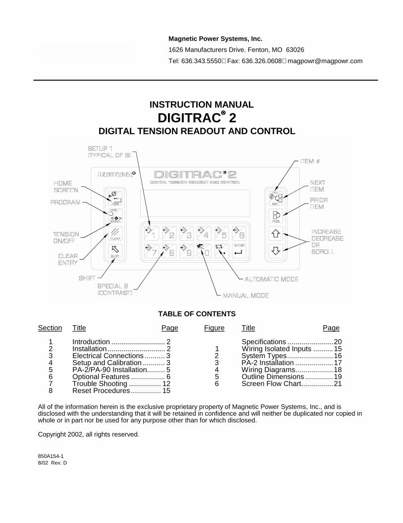
INSTRUCTION MANUALDIGITRAC���� 2
DIGITAL TENSION READOUT AND CONTROL
TABLE OF CONTENTS
Section Title Page Figure Title Page
1 Introduction ........................... 2 Specifications .......................202 Installation............................. 2 1 Wiring Isolated Inputs ..........153 Electrical Connections .......... 3 2 System Types.......................164 Setup and Calibration ........... 3 3 PA-2 Installation ...................175 PA-2/PA-90 Installation......... 5 4 Wiring Diagrams...................186 Optional Features ................. 6 5 Outline Dimensions ..............197 Trouble Shooting ................ 12 6 Screen Flow Chart................218 Reset Procedures ............... 15
All of the information herein is the exclusive proprietary property of Magnetic Power Systems, Inc., and isdisclosed with the understanding that it will be retained in confidence and will neither be duplicated nor copied inwhole or in part nor be used for any purpose other than for which disclosed.
Copyright 2002, all rights reserved.
850A154-18/02 Rev. D

1. INTRODUCTION
The MAGPOWR� Model DIGITRAC� 2 is a microprocessor based control, designed for precise closed looptension control of a moving web. All data entry and calibration is done through the touch pad keyboard. TheDIGITRAC 2 is capable of controlling web tension in unwind, rewind, or point-to-point applications. Throughoutthis manual, bold words or symbols represent keystrokes.
2. INSTALLATION
INSTALLATION
The DIGITRAC 2, Model D2E and its variants are intended for mounting on any flat vertical surface capable ofsupporting it. See Figure 4 for dimensions. The D2E meets the environmental and mechanical requirements ofEN50178 with the exception that the degree of protection provided by the D2E enclosure is IP65 which is morestringent than the standard. If the IP65 rating is required in the final installation, sealing type cable grips shouldbe used for cable entry. Four mounting holes are provided for attachment of the D2E to the mounting surface. The means of attachment should comply with the essential requirements of the appropriate standard(s) and isthe responsibility of the installer.
The DIGITRAC 2, Model D2 and its variants are intended for installation through a DIN panel opening. Thepanel itself should exhibit sufficient strength to support the weight of the D2 as well as insure the integrity of theenvironmental seal. The D2 maintains a degree of protection of IP65 over its front panel. It also meets theenvironmental and mechanical requirements of EN50178. The D2 mounting clips found on both sides of theenclosure behind the front panel will accommodate panel thickness of 0.06 inches (1.5mm) to 0.5 inches(12mm).
Wiring to and from the enclosure must be done with double or reinforced insulation or protective screening whichprovides protective separation. All wiring outside either of the DIGITRAC 2 enclosures should comply with theessential requirements of the appropriate standard(s) and is the responsibility of the installer.
If using a magnetic particle clutch or brake, see Section 5 to install the Model PA-2 or PA-90 Power Amplifier.
WARNING: DISCONNECT MAINS BEFORE OPENING ENCLOSURE
MAINTENANCE
The only maintenance that may be required on DIGITRAC 2 is fuse replacement. Replacement of any fuserequires opening the enclosure, which circumvents the enclosure IP rating. To replace a fuse:
On Model D2 and its variants: On Model D2E and its variants:
1. Disconnect the supply mains. 1. Disconnect the supply mains.2. Remove the two screws on the rear of the D2 2. Open the door of the D2E by loosening the which retain the top cover. two retaining screws.3. Remove the top cover. 3. Remove the PA-2 or PA-90 power amplifier4. Remove the PA-2 or PA-90 power amplifier if present. if present 4. Remove and replace the blown fuse.5. Remove and replace the blown fuse. 5. Re-install the PA-2 or PA-90.6. Re-install the PA-2 or PA-90 and the top cover. 6. Close the door and re-tighten the retaining screws.7. Reconnect supply mains. 7. Reconnect supply mains.
2

A = AUTOMATICS = STOPPINGH = HOLDM = MANUALE = E-STOP
OF TENSION
ANALOGBAR GRAPH
OF TENSIONREADOUTDIGITAL
UNITS &
CONFIGUREUSE
TO SELECT
LANGUAGE
SETUP #
STATUS
OFF
3. ELECTRICAL CONNECTIONS
Figure 3 shows the connections that are required for the basic DIGITRAC 2 system. They are:
115 or 230 vac powerOne or two MAGPOWR tension sensorsRUN/STOP using the DIGITRAC 2 internal logic supplyOUTPUT to clutch, brake, motor controller, etcPower Amplifier input (if used) 115 vac for 90 vdc clutch or brake, or 24 vdc for a 24 vdc clutch or brake.
See Section 6 for other options and connections.
Route AC power away from sensor and control wiring. MAGPOWR sensor cables are color coded on thenameplate. Run all wiring in shielded cable. Connect shields to the enclosure using the standoffs provided. Maximum shield length and maximum length of wires outside of the shield is 3 inches (75 mm).
4. SETUP AND CALIBRATION
Apply power.Screen contrast can be adjusted using SHIFT,B and � or�.
The home screen (above) always appears at power up. HOME also returns you to this screen.
Keyboard Layout and Programming See Cover for keypad layout.
CLEAR clears numeric inputs and other keystrokes.SHIFT selects the shifted (white) functionsNEXT and PRIOR change to next or prior screens. � or � change the value of the parameter displayed on thescreen. See Figure 6 for a complete programming flow chart.
3

4.1 System Set up
Basic calibration cannot be performed if E-STOP is open,or if RUN/STOP is in run mode.
A complete flow chart is shown in Figure 6.
To begin basic calibration, do the following:Press SHIFT,Press PROGram,Use or to select �PROGRAM: CALIBRATE�,Press NEXT to select �CALIBRATE BASIC�,Press NEXT to display �SELECT SYSTEM�.
Use � or � to select desired system type. See Figure 1 for adescription of system types. If using a regenerative drive, seeSection 6.9 to determine system type.
Then continue through the flow chart at right entering thedesired data in each screen.
4.2 Tension Sensor Calibration
NOTE: Continuing beyond this point will erase anyprevious sensor calibration in this setup.
Sensor calibration will require loading the sensor rollwith a known force. The known force will be appliedusing a weight and a temporary web as shown below.The temporary web should be threaded as the webwould normally be threaded in the machine to ensurethe same wrap angles. In wide web applications, theknown force should be applied near the center of thesensing roll using a narrow web such as a rope.
Follow the steps at the right to calibrate the tensionsensors.
4
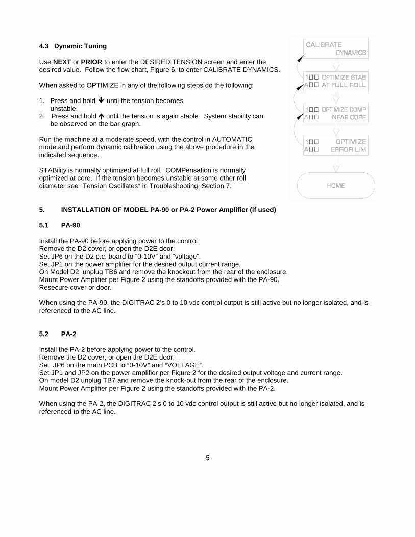
4.3 Dynamic Tuning
Use NEXT or PRIOR to enter the DESIRED TENSION screen and enter thedesired value. Follow the flow chart, Figure 6, to enter CALIBRATE DYNAMICS.
When asked to OPTIMIZE in any of the following steps do the following:
1. Press and hold � until the tension becomes unstable. 2. Press and hold � until the tension is again stable. System stability can be observed on the bar graph.
Run the machine at a moderate speed, with the control in AUTOMATICmode and perform dynamic calibration using the above procedure in theindicated sequence.
STABility is normally optimized at full roll. COMPensation is normallyoptimized at core. If the tension becomes unstable at some other rolldiameter see �Tension Oscillates� in Troubleshooting, Section 7.
5. INSTALLATION OF MODEL PA-90 or PA-2 Power Amplifier (if used)
5.1 PA-90
Install the PA-90 before applying power to the controlRemove the D2 cover, or open the D2E door.Set JP6 on the D2 p.c. board to “0-10V” and “voltage”.Set JP1 on the power amplifier for the desired output current range.On Model D2, unplug TB6 and remove the knockout from the rear of the enclosure.Mount Power Amplifier per Figure 2 using the standoffs provided with the PA-90.Resecure cover or door.
When using the PA-90, the DIGITRAC 2’s 0 to 10 vdc control output is still active but no longer isolated, and isreferenced to the AC line.
5.2 PA-2
Install the PA-2 before applying power to the control.Remove the D2 cover, or open the D2E door.Set JP6 on the main PCB to �0-10V� and �VOLTAGE�.Set JP1 and JP2 on the power amplifier per Figure 2 for the desired output voltage and current range.On model D2 unplug TB7 and remove the knock-out from the rear of the enclosure.Mount Power Amplifier per Figure 2 using the standoffs provided with the PA-2.
When using the PA-2, the DIGITRAC 2’s 0 to 10 vdc control output is still active but no longer isolated, and isreferenced to the AC line.
5

6. OPTIONAL CONNECTIONS, FUNCTIONS AND OTHER TECHNICAL INFORMATION
TABLE OF CONTENTSHARDWARE
ALTERNATE TENSION INPUTS ............................................................... 6.1DIAMETER INPUT ..................................................................................... 6.2WEB SPEED INPUT................................................................................... 6.3RUN/STOP ................................................................................................. 6.4E-STOP ...................................................................................................... 6.5REMOTE TENSION ON/OFF..................................................................... 6.6ISOLATED LOGIC INPUTS (RUN/STOP, ETC.) ....................................... 6.7SELECTING OUTPUT VOLTAGE/CURRENT........................................... 6.8+5 vdc SUPPLY .......................................................................................... 6.9
PROGRAM OPTIONS
OPERATOR SCREENS ............................................................................. 6.10UNITS OF MEASURE ................................................................................ 6.11LANGUAGE................................................................................................ 6.12MANUAL MODE ......................................................................................... 6.13TAPER TENSION....................................................................................... 6.14INERTIA COMPENSATION ....................................................................... 6.15HOLD LEVEL CONTROL........................................................................... 6.16OPTIMIZE METHOD .................................................................................. 6.17SETUPS AND COPY SETUPS .................................................................. 6.18SECURITY.................................................................................................. 6.19ITEM NUMBERS AND SCREEN DESCRIPTIONS.................................... 6.20
6.1 ALTERNATE TENSION INPUTS
100 mv/v TENSION SENSORS
On the main PCB cut jumpers JP11 and JP12.Connect wires to TB2 and TB3 as shown using shieldedwiring. Only one full bridge can be used. 10 vdc TENSION SIGNAL
On main PCB cut jumpers JP10, JP11, JP12 and JP13.Connect signal between terminals TB2.1(+) and TB2.2(-)using shielded wiring. TB2.2(-) should also be connected toTB3.1 (GND).
6.2 DIAMETER INPUT
The DIGITRAC 2 uses the diameter of the roll on unwinds and rewinds for inertia compensated stopping and onrewinds for providing taper tension. When no diameter input is provided the DIGITRAC 2 estimates diameter. Using a diameter input gives more accurate results.
Select the DIAMETER INPUT TYPE under PROGRAM-CONFIGURE. Connect a diameter sensor betweenTB3.7(+) and TB3.6(-) using shielded wiring.
VOLTAGE (0 to 10 vdc) Voltage must be proportional to diameter (i.e. the output at core cannot be 0 vdc). Select �VOLTAGE� on JP15 on the main PCB.
6

PULSE (0 to 5 vdc, 0 to10,000 pps) Diameter is calculated by dividing web speed by this signal, which isproportional to unwind/rewind RPM. Select �PULSE� on JP15 on main PCB. TB3.5 can be used to supply 5vdcto the pulse generator. See current limitation in Paragraph 6.9. A web speed signal must be provided if thediameter signal is �PULSE�.
6.3 WEB SPEED INPUT
The DIGITRAC 2 needs a web speed input if a PULSE type input is used to calculate diameter of the roll onunwinds and rewinds.
Select the SPEED INPUT TYPE under PROGRAM-CONFIGURE. Connect a web speed sensor betweenTB3.8(+) and TB3.6(-) using shielded wiring.
VOLTAGE (0 to 10 vdc) Select �VOLTAGE� ON JP9 on main PCB.
PULSE (0 to 5vdc, 0 to 10,000 pps) Select �PULSE� on JP9 on main PCB. TB3.5 can be used to supply 5 vdc tothe pulse generator. See current limitation in Paragraph 6.9.
6.4 LOGIC INPUTS
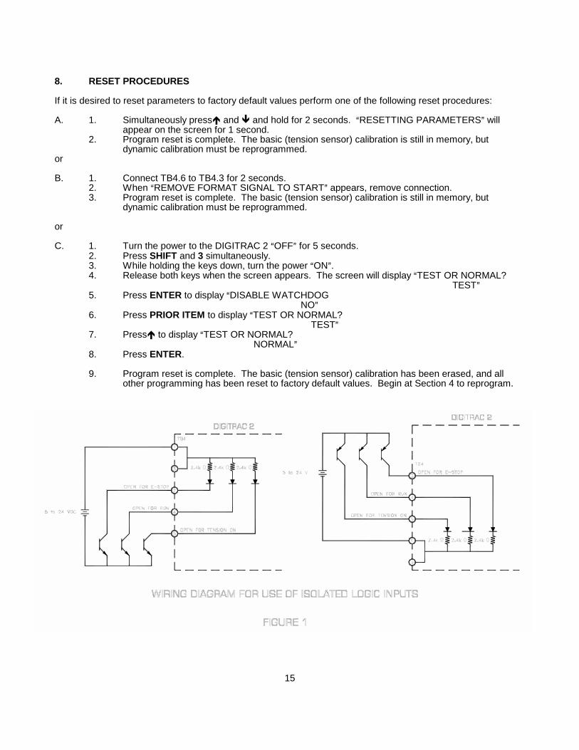
The logic inputs may be isolated with an external (5 to 24 vdc) power supply to interface with other equipment orfor increased noise immunity. Set JP7-8 (OPTO SUPPLY) to EXT (external) for an external isolated 5 to 24 vdcpower supply as shown in Figure 5. The current flowing in the logic inputs switches is 2 madc.
6.4.1 RUN/STOP
Connect TB4.4 to TB4.3 to initiate the stopping function. During STOP TIME the DIGITRAC 2 continues tocontrol tension as a closed loop system but INERTIA COMP and STOP MULTIPLIER are also activated.
See Section 6.7 to use isolated logic inputs (5 to 24vdc).
6.4.2 E-STOP (E-STOP IS AN AUXILIARY FUNCTION NOT INTENDED TO PROVIDE CATEGORY 1 SAFETY PROTECTION)
Open the connection between TB4.2 and TB4.1 to initiate E-STOP. On unwinds the output goes full on. On allother systems the output goes to zero.
See Section 6.7 to use isolated logic inputs (5 to 24vdc).
6.4.3 REMOTE TENSION ON/OFF
TENSION OFF sets the output to zero for all types of systems. For Type 2 and 3 systems OUTPUT LEVEL willdisplay 100% since these systems are reverse acting (i.e. tension decreases with increasing output).
Either of two optional modes of operation are selected using PROGRAM-CONFIGURE.
TOGGLE duplicates TENSION ON/OFF on the keypad. A momentary connection should be made betweenTB4.5 and TB4.3 will toggle between TENSION ON and OFF. The TENSION ON/OFF key remains functional.
LEVEL turns TENSION OFF when TB4.5 is connected to TB4.3. The TENSION ON/OFF key is disabled.
See Section 6.7 to use isolated logic inputs (5 to 24vdc).
6.5 ISOLATED LOGIC INPUTS
If it is desired to isolate the logic inputs on TB4 to interface with other equipment or for increased noise immunity,an external power supply can be used as shown in Figure 15. On the main PCB set JP8-7 (OPTO SUPPLY) toEXT (external).
7

6.6 SELECTING OUTPUT VOLTAGE/CURRENT
The output voltage/current at TB5.1(+) and TB5.2(-) is set by positioning jumpers on JP6 as shown below. JP6must be set for 0 to 10 vdc when the PA-2 or PA-90 Power Amplifier is used.
The –10 vdc to +10 vdc output is normally used with regenerative drives in torque mode. If the drive is wired sothat +10vdc creates torque in the first quadrant, use SYSTEM TYPE 2 or 4. Otherwise use SYSTEM TYPE1 or 3. In either case tension can now increase or decrease from T1 to T2. See Figure 1.
If the PA-2 or PA-90 Power Amplifier is used, select current and voltage per Figure 2.
6.7 +5vdc SUPPLY (TB3.5(+) to TB3.6(-))
Total current capacity is 150 madc. Subtract sensor current of:
30 madc per MAGPOWR sensor45 madc per 120 ohm sensor connected per Section 6.1
6.8 OPERATOR SCREENS
The operator screens are those normally used during machine operation and are accessed using NEXT ITEM orPRIOR ITEM from the HOME screen. These are the only screens affected by the language selected per Section6.10 and the only screens which are accessible when security is set per Section 6.17. The operator screens are�TENSION�, �DESIRED TENSION�, �MANUAL LEVEL�, �OUTPUT LEVEL�, �TAPER PERCENT� (if TAPERTENSION is selected), and �WEB SPOOL WIDTH� (if INERTIA COMPENSATION is selected).
6.9 UNITS OF MEASURE
PROGRAM-CONFIGURE can be used to select units of measure from:
ENGLISH (lb, in)METRIC (kg, mm)METRIC (n, mm)
6.10 LANGUAGE
PROGRAM-CONFIGURE can be used to select different languages. The selected language is used for theoperator screens which are �TENSION�, �DESIRED TENSION�, �MANUAL LEVEL�, �OUTPUT LEVEL�, �TAPERPERCENT� and �WEB SPOOL WIDTH�. The available languages are:
ENGLISH (factory default)FRANCAISDEUTSCHESPANOLITALIANO
8
6.11 MANUAL MODE
Switch to MANUAL mode at any time using SHIFT,. The output is now fixed at the level set in the MANUALLEVEL screen. Switch back to AUTOMATIC mode using SHIFT,
6.12 TAPER TENSION
Taper tension is used on rewinds to make better rolls by reducing full roll tension compared to core tension. UsePROGRAM-CONFIGURE to select TAPER TENSION. Input the CORE DIAMETER and FULL ROLLDIAMETER. TAPER PERCENT can now be entered on an operator screen. Percent taper is defined as thepercent decrease in tension from core to full roll.
If a diameter input is not used the DIGITRAC 2 estimates diameter. More accurate results are obtained if adiameter input is provided. See Section 6.2. Either way, diameter must be calibrated using PROGRAM-CALIBRATE-DIAMETER. When calibrating diameter, set TAPER PERCENT to 0.
6.13 INERTIA COMPENSATION
Extra torque is often needed to help stop large unwind rolls. STOP MULTIPLIER is available to increase theoutput as a multiple of the present running torque. If better stopping results are required, they can be attained byselecting INERTIA COMP using PROGRAM-CONFIGURE.
The DIGITRAC 2 asks for information needed to calculate the inertia of the unwind roll. The DIGITRAC 2 needsthis information to calculate the inertia and required stopping torque as the roll diameter changes.
If a diameter input is not used, the DIGITRAC 2 estimates diameter. More accurate results are obtained if adiameter input is provided. See Section 6.2. Either way, diameter must be calibrated using PROGRAM-CALIBRATE-DIAMETER. You must select INERTIA COMP before calibrating diameter.
Diameter must be calibrated while the machine is running, so required stopping torque can becalculated.
The DIGITRAC 2 must also know roll width to calculate roll inertia. A new screen now appears in the operatorloop to input this information when INERTIA COMP is selected.
6.14 HOLD LEVEL CONTROL
During normal automatic operation the output changes to correct for changes in DESIRED TENSION, rolldiameter, etc. During the STOP TIME the DIGITRAC 2 is still in automatic mode, but the output is momentarilychanged by STOP MULTIPLIER or INERTIA COMP to help stop the unwind roll. At the end of STOP TIME theDIGITRAC 2 switches to HOLD mode. In HOLD mode the output is fixed at the HOLD LEVEL. PROGRAM-CONFIGURE can be used to set HOLD LEVEL CHANGES WITH TENSION and / or HOLD LEVEL CHANGESWITH DIAMETER.
6.15 OPTIMIZE METHOD
You should normally select PI (Proportional-Integral) for tension control applications. OPTIMIZE changes P andI to give optimum response. For special applications PID (Proportional-Integral-Derivative) can be selectedusing PROGRAM-CONFIGURE.
9

6.16 SETUPS AND COPY SETUPS
There are six independent setups. Each contains its own complete set of parameters. Switch between setupsonly while stopped using SHIFT, 1, etc. Each setup can be calibrated individually as described in Section 4, orthe sensor calibration and parameters in any one setup can be copied to any other setup. Complete setups canbe copied using PROGRAM-COPY SETUPS. COPY SETUPS always copies from a selected setup to thepresent setup. You can also copy the factory DEFAULTS to the present setup.
6.17 PROGRAM-SECURITY
PROGRAM-SECURITY can be used to prevent changes to all the programming parameters. When secured,only values in the operator screens can be changed.
6.18 ITEM NUMBERS AND SCREEN DESCRIPTIONS
The numbers following each screen parameter can be used to change the value using SHIFT, ITEM.
OPERATOR SCREENS
TENSION Displays current measured tension, setup number and operating mode.
DESIRED TENSION (18) The tension set point for AUTOMATIC mode and STOPPING mode. (Does not appear when taper tension is used).
CORE TENSION (18) This is the DESIRED TENSION at CORE DIAMETER when tapertension is used.
MANUAL LEVEL (48) The output set point percent when in MANUAL mode.
OUTPUT LEVEL Current output as a percent of maximum.
TAPER PERCENT (20) Appears only when taper tension is used. The core tension is reducedby this percentage as the rewind roll increases to FULL ROLLDIAMETER.
WEB SPOOL WIDTH (10) Appears only when inertia comp is used. Enter the width of the presentweb to enable calculation of roll inertia.
PROGRAM-PARAMETER SCREENS
BAR GRAPH TIME (29) Update time for the tension / output bar graph.Default is .050 sec.
DERIVATIVE TIME (34) Part of PID control. Gives an output adjustment proportional to the rateof change of tension error. Error is the difference between the desiredtension and the measured tension.
ERROR LIMIT (19) This value limits the percent of error that is acted upon.
HOLD LEVEL (26) The output will stay at this percent level while in HOLD mode.
INTEGRATOR TIME (32) This time adjusts the response to errors. Larger values slow down theresponse to rapidly changing error.
NUMERIC DISPLAY TIME (28) Update time for the tension / output digital readout.
OUTPUT LIMIT (21) The output will not go above this percent of maximum.

PROPORTIONAL GAIN (33) Generates an output adjustment proportional to the error.
START TIME (22) Provides a soft-start when starting with a slack web. The output islimited to the HOLD LEVEL at start, but the limit level is increased withtime. This is the time taken to increase the limit to full output. A longerstart time will provide a softer start.
STOP MULTIPLIER (24) Upon receipt of a stop signal, the output is increased by this multiplier(1 creates no increase). Since the output is proportional to rolldiameter, this is a simple adjustment for roll inertia.
STOP TIME (23) This is the time that DIGITRAC 2 stays in STOPPING (automatic)mode after the stop signal is received. At the end of this time thecontrol goes to HOLD mode. Stop time should be slightly longer thanactual machine stopping time.
PROGRAM-CONFIGURE SCREENS
DIAMETER INPUT TYPE (11) NONE, VOLTAGE, or PULSE.
IS INERTIA COMP USED YES, NO
IS TAPER TENSION USED YES, NO
HOLD LEVEL CHANGESWITH DIAMETER
YES, NO
HOLD LEVEL CHANGESWITH TENSION
YES, NO
OUTPUT RANGE Normal, -10 vdc to +10 vdc
OPTIMIZE METHOD (44) PI or PID.
SELECT LANGUAGE ENGLISH, FRANCAIS, DEUTSCH, ESPANOL, or ITALIANO
SELECT UNITS (42) (lb, in), (kgm, mm), (n, mm)
SPEED INPUT TYPE (47) NONE, VOLTAGE, or PULSE.
TENSION ON/OFF TOGGLE, LEVEL.
The following appear only if taper tension is used:
CORE DIAMETER (14) CORE TENSION is commanded at this diameter.
FULL ROLL DIA. (12) At this diameter the tension will be reduced by the taper percent.
11

The following appear only if inertia comp is used:
DIAMETER AT THIS WEIGHT The roll diameter at the entered weight. Diameter must becalibrated while the web is running. It is not necessary to calibrateat the maximum velocity.
ROLL WEIGHT The roll weight at any diameter in lbs or kgm.
RUNNING VELOCITY The maximum running web velocity. Typical velocity can be used.
TIME TO ZERO SPEED The time it takes the machine to stop when running at the abovevelocity.
WIDTH AT THIS WEIGHT This width is used to calculate density for the above roll weight.
7. TROUBLE SHOOTING
PROBLEM POSSIBLE CAUSE SOLUTION OR DIAGNOSTIC
Screen blank or hard to read Contrast misadjusted
Power select switchimproperly set.
Press SHIFT, B and � or � to adjust.
Set 115/230 vac power select switch to theappropriate voltage.
Output always low TENSION ON/OFF set toOFF
If REMOTE TENSION ON/OFF is set to�TOGGLE� press TENSION ON/OFF on thekeypad once.
If REMOTE TENSION ON/OFF is set to�LEVEL� one or more of the remote tensionoff switches are closed.
E-STOP is active (exceptunwind).
E-STOP is wired incorrectly.
JP8-7 not set for the properlogic supply.
If the internal logic is being used (the factorydefault) TB4.2 must be connected to TB4.1to disable E-STOP. Also verify JP8-7 set to�INT�.
If an external logic supply is used seeSection 6.5.
Output always high E-STOP is active (unwindsonly).
E-STOP is wired incorrectly.
JP8-7 not set for the properlogic supply.
See above.
Cannot enter PROGRAM,CALIBRATE, BASIC
Not in HOLD mode:
RUN/STOP not wiredcorrectly.
JP8-7 not set for the properlogic supply.
If the internal logic supply is being used (thefactory default) TB4.4 must be connected toTB4.3 to be in HOLD mode. Also verifyJP8-7 set to �INT�.
If an external logic supply is used seeSection 6.5.
�EXCESSIVE ROLLWEIGHT�
Sensor(s) misapplied The total weight of the sensor idler roll andshaft must be less than � of sensor rating. When two sensors are used this is thecombined rating of both (i.e. 100 lbs for two50 lb sensors).

�MAXIMUM TENSION TOOHIGH�
Selected maximum tension isout of sensor range.
Calibration can be completed by using asmaller maximum tension. See �Maximumtension is out of range� below.
�SENSOR SIGNAL TOOLOW�
Maximum tension is out ofsensor range.
1. This problem is often caused by loadingthe sensor in the wrong direction. It can becorrected by reversing +SIG and -SIG(TB2-1 and TB2-2).
2. If signal direction is correct, calibrationcan often be completed by using alarger maximum tension. See�Maximum tension is out of range� below.
Maximum tension is out ofsensor range.
When maximum tension is applied the loadon the sensors must be less than the totalsensor rating and greater than 1/8 of totalsensor rating. When two sensors are usedthis is the combined rating of both (i.e.100 lbs for two 50 lbs sensors). Calculatethis load from:
LOAD = 2*MAX*SIN(WRAP/2)where:MAX = maximum tension entered duringsensor calibration.WRAP=wrap angle.
Tension oscillates DIAGNOSTIC:1. From the home screen use NEXT orPRIOR to go to OUTPUT LEVEL.2. While the machine is running record theapproximate output level.3. Enter this value in the MANUAL LEVEL.4. Switch to MANUAL mode.5. If the tension continues to oscillate thereis an out of round roll or other machinegenerated tension variation.6. If oscillation stops the control may bemistuned. See “ERROR LIM needsadjustment.”
ERROR LIM needsadjustment
1. Go to OPTIMIZE ERROR LIM.2. Press and hold � until the oscillation stops.If ERROR LIM is max go to �COMP needsadjustment�.
COMP needs adjustment 1. Go to OPTIMIZE COMP (ignore referenceto core).2. Press and hold � until the oscillationstops.3. If oscillations cease, optimize ERRORLIMIT.3. If COMP is max go to �STAB needs
adjustment�.
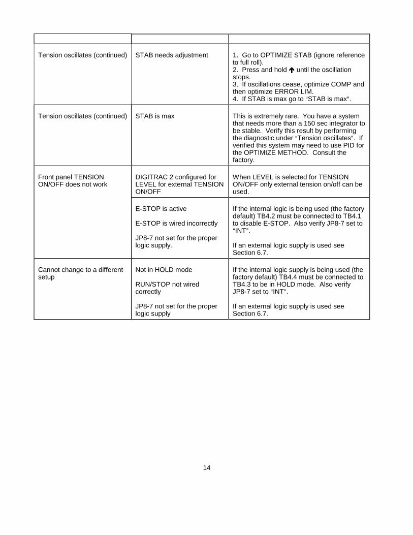
Tension oscillates (continued) STAB needs adjustment 1. Go to OPTIMIZE STAB (ignore referenceto full roll).2. Press and hold � until the oscillationstops.3. If oscillations cease, optimize COMP andthen optimize ERROR LIM.4. If STAB is max go to �STAB is max�.
Tension oscillates (continued) STAB is max This is extremely rare. You have a systemthat needs more than a 150 sec integrator tobe stable. Verify this result by performingthe diagnostic under �Tension oscillates�. Ifverified this system may need to use PID forthe OPTIMIZE METHOD. Consult thefactory.
Front panel TENSIONON/OFF does not work
DIGITRAC 2 configured forLEVEL for external TENSIONON/OFF
When LEVEL is selected for TENSIONON/OFF only external tension on/off can beused.
E-STOP is active
E-STOP is wired incorrectly
JP8-7 not set for the properlogic supply.
If the internal logic is being used (the factorydefault) TB4.2 must be connected to TB4.1to disable E-STOP. Also verify JP8-7 set to�INT�.
If an external logic supply is used seeSection 6.7.
Cannot change to a differentsetup
Not in HOLD mode
RUN/STOP not wiredcorrectly
JP8-7 not set for the properlogic supply
If the internal logic supply is being used (thefactory default) TB4.4 must be connected toTB4.3 to be in HOLD mode. Also verifyJP8-7 set to �INT�.
If an external logic supply is used seeSection 6.7.
14
8. RESET PROCEDURES
If it is desired to reset parameters to factory default values perform one of the following reset procedures:
A. 1. Simultaneously press� and � and hold for 2 seconds. �RESETTING PARAMETERS� willappear on the screen for 1 second.
2. Program reset is complete. The basic (tension sensor) calibration is still in memory, butdynamic calibration must be reprogrammed.
or
B. 1. Connect TB4.6 to TB4.3 for 2 seconds.2. When �REMOVE FORMAT SIGNAL TO START� appears, remove connection.3. Program reset is complete. The basic (tension sensor) calibration is still in memory, but
dynamic calibration must be reprogrammed.
or
C. 1. Turn the power to the DIGITRAC 2 �OFF� for 5 seconds.2. Press SHIFT and 3 simultaneously.3. While holding the keys down, turn the power �ON�.4. Release both keys when the screen appears. The screen will display �TEST OR NORMAL?
TEST�5. Press ENTER to display �DISABLE WATCHDOG
NO�
6. Press PRIOR ITEM to display �TEST OR NORMAL? TEST�
7. Press� to display �TEST OR NORMAL? NORMAL�
8. Press ENTER.
9. Program reset is complete. The basic (tension sensor) calibration has been erased, and allother programming has been reset to factory default values. Begin at Section 4 to reprogram.
15

16

17

18

19

DIGITRAC���� 2 SpecificationsSupply Voltage 115 or 230 volts rms, �10%Supply Frequency: 50 or 60 cycles per second, sinusoidal
Fuses: F1, F2 1.6 amp, Littelfuse Part No. 21601.6, orWickmann Part No. 19194-053-FS
EnclosureD2 Front Panel IP65 (IEC529)
Enclosure IP20 (IEC529)D2E IP65 (IEC529)
Climatic Class: 3K3 (EN60721)Temperature Range:Operating 0�C to 40�CStorage -30�C to +80�CRelative Humidity 5% to 85%Pollution Degree: 2 (IEC664-1)Altitude: 0 to 2000 m
Compatible Residual Current Devise Types: A or B (IEC755)Worst Case Fault Current: 1.6 amp
Inputs:Tension Sensor 2.1 mvdc using +5 and -5 vdc (10 vdc)
across one 350 ohm sensor or two 350 ohm sensors in parallel, or100 mvdc, using 5 volts across one 100 ohm full bridge,
or0 to +10 vdc analog
Diameter 0 to +10 vdc analog, or20 to 10,000 pulses per second, 5 volt TTL
Web Speed 0 to +10 volts analog, or20 to 10,000 pulses per second, 5 volt TTL
E-Stop switch closure or 5 vdc or 24 vdc logicRun/Stop switch closure or 5 vdc or 24 vdc logicTension Off switch closure or 5 vdc or 24 vdc logicFormat switch closure or 5 vdc or 24 vdct logic
Outputs:Torque 0 to +10 vdc., 1 madc maximum
4 to 20 madc, 500 ohms maximum-10 to +10 vdc, 1 madc maximum
Tension Reference 0 to +5 vdc., 1 madc maximum
20

