digital thermostat installation instructions - home · pdf file ·...
TRANSCRIPT

DIGITAL THERMOSTAT MODEL P374-1100FM
InstallationInstructions
Replacement Components Division Carrier Corporation 11/98
TOTALINE
MULTI-STAGE PROGRAMMABLE
HEATPUMP
HEATCOOL
&72
74
70
Am
COOL
HEAT
AUTO
MoI2:00

Table Of Contents
PREPARATION
REMOVE OLD THERMOSTAT
INSTALL WIRE CONNECTOR
WIRING DIAGRAMS
CALIBRATION
TEST OPERATION
TROUBLESHOOTING
Page 1
Model No. P374-1100FM
CAUTION Follow Installation Instructions carefully.
DISCONNECT POWER TO THE HEATER - AIR CONDITIONER BEFORE REMOVINGTHE OLD THERMOSTAT AND INSTALLINGTHE NEW THERMOSTAT. WARNING
2
3
4
5
8
10
9
Replacement Components Division - Carrier Corporation
This device complies with Part 15 of the FCC rules. Operation is subject to the following 2 conditions: (1) This device may not cause harmful interference, and (2) This device must accept any interference received, including interference that may cause undesired operation.
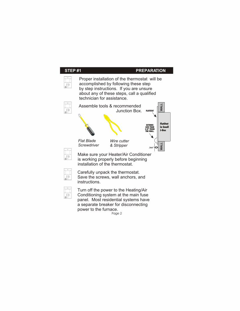
Proper installation of the thermostat will beaccomplished by following these stepby step instructions. If you are unsureabout any of these steps, call a qualifiedtechnician for assistance.
Assemble tools & recommended Junction Box.
Flat BladeScrewdriver
Wire cutter& Stripper
Make sure your Heater/Air Conditioneris working properly before beginninginstallation of the thermostat.
Carefully unpack the thermostat.Save the screws, wall anchors, and instructions.
STEP #1 PREPARATION
Page 2
Turn off the power to the Heating/AirConditioning system at the main fusepanel. Most residential systems have a separate breaker for disconnectingpower to the furnace.
EXTENDSLESS THAN3/8” FROMTHE WALL.
FLATSTAT
.366”
FlatStatin SmallJ-Box
WA
LL
WA
LL
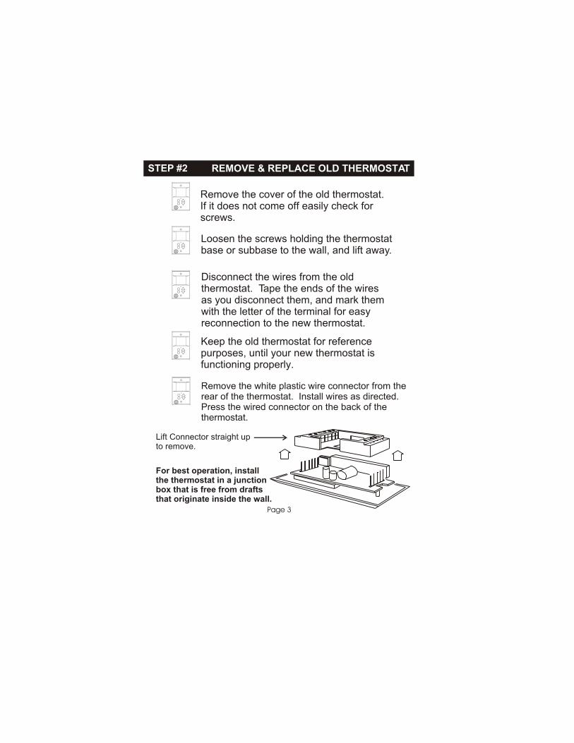
Remove the cover of the old thermostat.If it does not come off easily check forscrews.
Loosen the screws holding the thermostatbase or subbase to the wall, and lift away.
Disconnect the wires from the oldthermostat. Tape the ends of the wiresas you disconnect them, and mark themwith the letter of the terminal for easyreconnection to the new thermostat.
STEP #2 REMOVE & REPLACE OLD THERMOSTAT
Page 3
Keep the old thermostat for referencepurposes, until your new thermostat isfunctioning properly.
Remove the white plastic wire connector from therear of the thermostat. Install wires as directed.Press the wired connector on the back of the thermostat.
Lift Connector straight upto remove.
For best operation, installthe thermostat in a junctionbox that is free from draftsthat originate inside the wall.

STEP #3 WIRE CONNECTIONS
Page 4
If the terminal designations on your oldthermostat do not match those on the new thermostat, refer to the chart below,or the wiring diagrams that follow.
* C may not be used on all systems. ** O/B is used if your system is a Heat Pump.
Wire from theold thermostat
terminal markedFunction
Install on thenew thermostat
connector marked
G or F Fan G
Y1, Y or C Cooling Y1
W1, W or H Heating W1,O,B
W1,O,B**
PowerRh, R, M, Vr, A R
C
O/B
C *Common
Rev. Valve
Y2 Y2
W2 W2
2nd Stage Cool
2nd Stage Heat
RS+5 RS+5 Remote Sensor +5vdc
RS RSRemote Sensor Signal
RS G GNDRemote Sensor Ground
CK1
CK2
Dry Contact Switch 1
Dry Contact Switch 2

Sample Wiring Diagrams
Thermostat
Thermostat
Page 5
R
C
G
Y1
Y2
W1
W2
O
E
L
R CGY1Y2 W1W2O
24 vac common
24 vac return
fan relay
compressor relay
1st stage heat circuit
R
C
G
Y1
Y2
W1
W2
O
E
L
R CGY1Y2 W1W2O
24 vac return
fan relay
compressor relay
1st stage heat circuit
5 Wire, 1 Stage Cooling, 1 Stage Gas Heat
4 Wire, 1 Stage Cooling, 1 Stage Gas Heat
Residential Gas or Electric Heat *,Electric Cool, split systems & packageunits
Residential Gas or Electric Heat *, Electric Cool, split systems & packageunits
* If using electric heat this option must be selected on during advanced setup.
* If using electric heat this option must be selected on during advanced setup.

Sample Wiring Diagrams
Page 6
R
C
G
Y1
Y2
W1
W2
O
E
L
R CGY1Y2 W1W2O
24 vac common
24 vac return
fan relay
compressor relay
2nd stage compressor relay
1st stage heat circuit
R
C
G
Y1
Y2
W1
W2
O
E
L
R CGY1Y2 W1W2O
24 vac common
24 vac return
fan relay
compressor relay
1st stage heat circuit
2nd stage heat circuit
Residential 2 Stage Cooling, withGas or Electric Heat*
Residential & commercial 1 Stage Cooling,with 2 Stage Gas or Electric Heat*
6 Wire, 2 Stage Cooling, 1 Stage Heat
6 Wire, 1 Stage Cooling, 2 Stage Heat
Thermostat
Thermostat
* If using electric heat, this option must be selected during advanced setup.
Sample Wiring Diagrams
Page 7
R
C
G
Y1
Y2
W1
W2
O
E
L
R CGY1Y2 W1W2O
24 vac common
24 vac return
fan relay
compressor relay
2nd stage compressor relay
1st stage heat circuit
2nd stage heat circuit
R
C
G
Y1
Y2
W1
W2
O
E
L
R CGY1Y2 W1W2O
24 vac common
24 vac return
fan relay
compressor relay
reversing valve
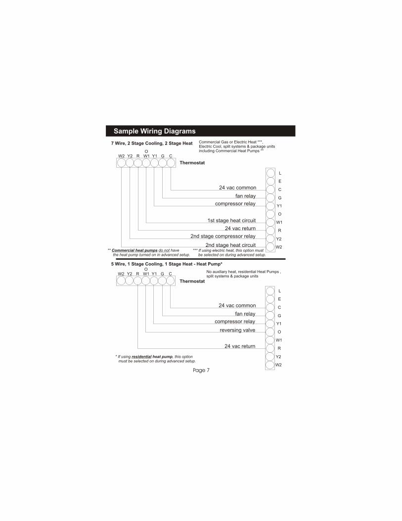
Commercial Gas or Electric Heat ***,Electric Cool, split systems & package unitsincluding Commercial Heat Pumps **
No auxiliary heat, residential Heat Pumps ,split systems & package units
7 Wire, 2 Stage Cooling, 2 Stage Heat
5 Wire, 1 Stage Cooling, 1 Stage Heat - Heat Pump*
Thermostat
Thermostat
* If using residential heat pump, this option must be selected on during advanced setup.
** Commercial heat pumps do not have the heat pump turned on in advanced setup.
*** If using electric heat, this option must be selected on during advanced setup.
Sample Wiring Diagram
Calibration
Page 8
R
C
G
Y1
Y2
W1
W2
O
E
L
R CGY1Y2 W1W2O
24 vac common
24 vac return
fan relay
compressor relay
1st stage heat circuit
2nd stage heat circuit
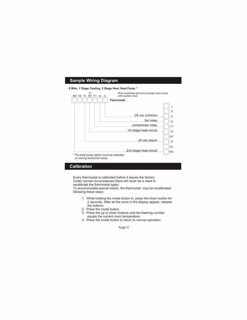
6 Wire, 1 Stage Cooling, 2 Stage Heat, Heat Pump *
Most residential split and package heat pumpswith auxiliary heat
Thermostat
* The heat pump option must be selected on during advanced setup.
Every thermostat is calibrated before it leaves the factory.Under normal circumstances there will never be a need torecalibrate the thermostat again.To accommodate special needs, the thermostat may be recalibratedfollowing these steps:
1. While holding the mode button in, press the down button for 2 seconds. After all the icons in the display appear, release the buttons.2. Press the mode button.3. Press the up or down buttons until the flashing number equals the current room temperature.4. Press the mode button to return to normal operation.
STEP #4 TEST OPERATION
Page 9
Press the MODE button repeatedly untilthe HEAT icon appears on the display.Press the up/down buttons until the settemperature is 10 degrees above roomtemperature. The furnace should turn on.
Press the MODE button repeatedly untilthe COOL icon appears on the display.Press the up/down buttons until the set temperature is 10 degrees below roomtemperature. The air conditioner shouldturn on. NOTE: Most equipment has atime delay of 5 minutes between coolcycles. This feature is defeatable on thethermostat. Consult the Owner's Manualunder Setup, cycles per hour.
Turn the power on to the Heating/AirConditioning system.
Press the MODE button to OFF. Pressthe FAN button to Fan On. The fanshould turn on and run continuously.
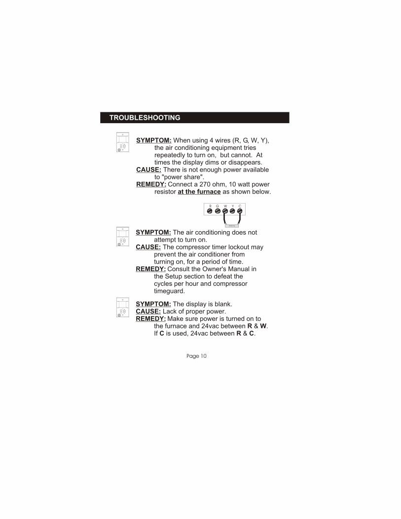
SYMPTOM: When using 4 wires (R, G, W, Y), the air conditioning equipment tries repeatedly to turn on, but cannot. At times the display dims or disappears.CAUSE: There is not enough power available to "power share".REMEDY: Connect a 270 ohm, 10 watt power resistor at the furnace as shown below.
TROUBLESHOOTING
Page 10
SYMPTOM: The air conditioning does not attempt to turn on.CAUSE: The compressor timer lockout may prevent the air conditioner from turning on, for a period of time.REMEDY: Consult the Owner's Manual in the Setup section to defeat the cycles per hour and compressor timeguard.
R G W Y C
TR300-10w
SYMPTOM: The display is blank.CAUSE: Lack of proper power.REMEDY: Make sure power is turned on to the furnace and 24vac between R & W. If C is used, 24vac between R & C.

SYMPTOM: When controlling a residential heat pump, and asking for cooling, the heat comes on.CAUSE: Heat pump is not selected "on" in the Advanced Setup.REMEDY: Select heat pump on during Advanced Setup programming. Consult the Owner's Manual.
TROUBLESHOOTING
Page 11
SYMPTOM: When calling for cooling, both the heat and cool come on.CAUSE: The Advanced Setup is configured to control a heat pump, and the hvac the thermostat is controlling is a "conventional" (non heat pump) system.REMEDY: Consult the Owner's Manual in the Advanced Setup section to turn off the heat pump.
P/N 88-114
4Z95
CcFFOR HOME OR OFFICE USE
Tested to Complywith FCC Standards
FlatStat P374-1100FM