digital tlz09/tlz10 cassette tape drive and tlz9l/tlz1l...
TRANSCRIPT

DIGITAL TLZ09/TLZ10 Cassette TapeDrive and TLZ9L/TLZ1L Autoloader
Owner's ManualPart Number: EK-TLZXX-OM. B01
February 1998
Digital Equipment CorporationMaynard, Massachusetts

February 1998
Digital Equipment Corporation makes no representations that the use of its products in the manner described in thispublication will not infringe on existing or future patent rights, nor do the descriptions contained in this publicationimply the granting of licenses to make, use, or sell equipment or software in accordance with the description.
© Digital Equipment Corporation 1998. All rights reserved.
The following FCC and VCCI notices apply to the tabletop devices. Embedded versions will be covered by similarnotices in the documentation for the system or storage enclosure in which they reside.
FCC NOTICE : The equipment described in this manual has been certified to comply with the limits for a Class Bcomputing device, pursuant to Subpart J of Part 15 of FCC Rules. Only peripherals (computer input/outputdevices, terminals, printers, et cetera) certified to comply with the Class B limits may be attached to this computer.Operation with noncertified peripherals may result in interference to radio and television reception. This equipmentgenerates and uses radio frequency energy and if not installed and used properly, that is, in strict accordance withthe manufacturer's instructions, may cause interference to radio and television reception. It has been type tested andfound to comply with the limits for a Class B computing device in accordance with the specifications in Subpart Jof Part 15 of FCC Rules, which are designed to provide reasonable protection against such interference in aresidential installation. However, there is no guarantee that interference will not occur in a particular installation. Ifthis equipment does cause interference to radio or television reception, which can be determined by turning theequipment off and on, the user is encouraged to try to correct the interference by one or more of the followingmeasures:
• Reorient the receiving antenna.
• Move the computer away from the receiver.
• Plug the computer into a different outlet so computer and receiver are on different branch circuits.
The tabletop versions require a shielded interface cable in order to comply with FCC emissions limits.
The following are trademarks of Digital Equipment Corporation: DECdirect, DECmailer, DECservice, DECstation,DIGITAL, OpenVMS, Q-bus, SERVICenter, StorageWorks, ULTRIX, VAXstation, VMS, and the DIGITAL logo.
Novell and NetWare are registered trademarks of Novell, Inc.Microsoft is a registered trademark and Windows NT is a trademark of Microsoft Corporation.Sony is a registered trademark of Sony Corporation.Sun and Solaris are registered trademarks and SunOS is a trademark of Sun Microsystems, Inc.IBM and AIX are registered trademarks and RS/6000 is a trademark of International Business MachinesCorporation.Hewlett-Packard and HP-UX are registered trademarks of Hewlett-Packard Company.
S3640

Für Bundesrepublik Deutschland
For Federal Republic of Germany
Pour la République féderal d'Allemagne
BESCHEINIGUNG DES HERSTELLERS/IMPORTEURS
Dieses Gerät ist in Übereinstimmung mit den Bestimmungen der BMPT Vfg.243/1991 und Vfg.46/1992 inVerbindung mit EN55022:1987 (DIN VDE 0878-3:11.89), oder Vfg.1046/1984 mit Vfg. 483/1986, funkentstört.Es trägt als Nachweis der EMV-Konformität entweder eine Konformitätskennzeichnung oder das VDE-Funkschutzzeichen.
Der vorschriftsmäßige Betrieb mancher Geräte (z.B. Meßsender) kann allerdings gewissen Einschränkungenunterliegen. Beachten Sie deshalb die unten aufgeführten Hinweise.
Für Geräte die nicht mit dem VDE-Funkschutzzeichen versehen sind wurde dem Bundesamt für Zulassungen in derTelekommunikation (BZT) das Inverkehrbringen dieses Gerätes angezeigt und die Berechtigung zur Überprüfungder Serie auf Einhaltung der Bestimmungen eingeräumt.
Betreiberhinweis
Wir sind verpflichtet, Sie auf folgende Fakten hinzuweisen (BMPT-Amtsblattverfügung 243/91 bzw. 1046/84 §2,Abschnitt 5):
Dieses Gerät wurde funktechnisch sorgfältig entstört und geprüft. Wird dieses Gerät innerhalb einer Anlagezusammen mit anderen Geräten betrieben, muß bei Inanspruchnahme der "Allgemeinen Betriebsgenehmigung"nach BMPT-AmtsblVfg. 243/91 bzw. 1046/84 die gesamte Anlage den unter §2, Abschnitt 1, genanntenVoraussetzungen entsprechen.
Externe Datenkabel
Sollte ein Austausch der von Digital spezifierten Datenkabel nötig werden, muß der Betreiber für eineeinwandfreie Funkentstörung sicherstellen, daß Austauschkabel im Aufbau und Abschirmqualität dem DigitalOriginalkabel entsprechen.

VCCI:

v
Table of Contents
1 TLZ09/9L and TLZ10/1L Cassette Tape Device Product Description
1.1 Overview .......................................................................................................... 1–11.1.1 System Support ....................................................................................... 1–2
1.2 Design Features................................................................................................. 1–21.2.1 What is Digital Audio Tape (DAT)?........................................................ 1–21.2.2 What is Digital Data Storage (DDS)? ...................................................... 1–21.2.3 What is the Media Recognition System (MRS)?...................................... 1–3
1.3 Drive/Loader Models ........................................................................................ 1–31.3.1 Checking Your Shipment for Model TLZ09/TLZ10 Tabletop Drives ...... 1–81.3.2 Checking Your Shipment for Model TLZ9L/TLZ1L Tabletop Autoloader1–81.3.3 Ordering Additional Cassettes ................................................................. 1–91.3.4 Visiting Web Site for the Latest Information ........................................... 1–9
2 Installing the Tabletop Drive or Autoloader
2.1 General ............................................................................................................. 2–12.2 Shut Down, Halt, and Power Off the System..................................................... 2–12.3 Selecting the SCSI Address............................................................................... 2–22.4 Connecting a SCSI Signal Cable --- Device to System ...................................... 2–32.5 Adding Another Tabletop Device --- Device to Device ..................................... 2–42.6 Connecting the Power Cable ............................................................................. 2–4
3 Installing the 3.5-Inch or 5.25-Inch Cassette Tape Drive
3.1 General ............................................................................................................. 3–13.2 Shut Down, Halt, and Power Off the System..................................................... 3–13.3 Selecting the Jumper and Switch Configuration for the Drive ........................... 3–1
3.3.1 SCSI ID Address Jumpers....................................................................... 3–2

vi
3.3.2 Other Optional Jumper Settings............................................................... 3–43.3.3 Drive Switch Settings.............................................................................. 3–4
3.4 Connecting a SCSI Signal Cable --- Drive to System ........................................ 3–63.5 Connecting the Power Cable and Mounting ...................................................... 3–6
4 Verifying TLZ09/TLZ10 Cassette Tape Drive Installation
4.1 General ............................................................................................................. 4–14.1.1 Execute POST......................................................................................... 4–1
5 Using the TLZ09/TLZ10 Cassette Tape Drive
5.1 General ............................................................................................................. 5–15.2 Power Switch.................................................................................................... 5–15.3 Unload Button .................................................................................................. 5–15.4 Tape Drive LEDs.............................................................................................. 5–2
5.4.1 Status LED.............................................................................................. 5–25.4.2 Tape LED ............................................................................................... 5–25.4.3 Busy LED ............................................................................................... 5–2
5.5 Using the Cassette Tape.................................................................................... 5–55.5.1 Proper Handling of Cassette Tapes.......................................................... 5–55.5.2 Setting the Write-Protect Tab on the Cassette Tape................................. 5–65.5.3 Inserting a Cassette Tape into the Drive .................................................. 5–7
6 Preventive Maintenance and Problem Solving
6.1 Introduction ...................................................................................................... 6–16.2 Cleaning the Heads ........................................................................................... 6–16.3 Problem Solving ............................................................................................... 6–3
6.3.1 System-Based Diagnostics ...................................................................... 6–46.4 Service Offerings .............................................................................................. 6–4
7 Using the TLZ9L/TLZ1L Cassette Tape Autoloader
7.1 Overview .......................................................................................................... 7–17.2 LED Indicators ................................................................................................. 7–27.3 TLZ9L LCD Panel............................................................................................ 7–8
7.3.1 Warning Indicator ................................................................................... 7–97.3.2 Write Protect Indicator...........................................................................7–107.3.3 Error Indicator .......................................................................................7–117.3.4 7-Segment Numeric Display ..................................................................7–117.3.5 Cartridge Number Indicators ..................................................................7–12

vii
7.4 TLZ1L Front Panel Buttons and LCD Panel....................................................7–127.4.1 Select and Enter Buttons .......................................................................7–127.4.2 Eject Button ..........................................................................................7–137.4.3 TLZ1L LCD Panel ................................................................................7–13
7.4.3.1 LCD Icon Area ............................................................................7–147.4.3.2 LCD Alphanumeric Display Area................................................7–15
7.5 TLZ9L/TLZ1L Operation ...............................................................................7–217.5.1 Automatic Operations............................................................................7–217.5.2 Manual Operations ................................................................................7–227.5.3 Magazine Operations.............................................................................7–23
7.5.3.1 Eight Cartridge Mode ..................................................................7–237.5.3.2 Seven Cartridge Mode .................................................................7–247.5.3.3 Single Cartridge Mode.................................................................7–247.5.3.4 Loading Cartridges Into the Magazine .........................................7–257.5.3.5 Loading the Magazine Into the Autoloader ..................................7–267.5.3.6 Ejecting the Magazine .................................................................7–277.5.3.7 Unloading Cartridges From the Magazine....................................7–287.5.3.8 Autoload Function .......................................................................7–29
7.6 Switch Settings ...............................................................................................7–297.6.1 Switchpack Settings ..............................................................................7–297.6.2 SCSI ID Select Switch (Tabletop Only).................................................7–30
7.7 Cleaning Requirements ...................................................................................7–30
A Cassette Tape Drive and Autoloader Specifications
B Product Notes for DIGITAL UNIX, OpenVMS, and Windows NT
DIGITAL UNIX TLZ09/TLZ9L/TLZ10/TLZ1L Compression and NoncompressionModes...................................................................................................................B–1
DIGITAL UNIX DUMP Utility ..............................................................................B–1OpenVMS TLZ09/TLZ9L/TLZ10/TLZ1L Compression and Noncompression
Modes...................................................................................................................B–2Windows NT TLZ09/TLZ9L/TLZ10/TLZ1L Compression and Noncompression
Modes...................................................................................................................B–2DIGITAL Operating System Support ......................................................................B–3
C Product Notes for Non-DIGITAL Platforms
Product Notes for Novell NetWare and Microsoft Windows NT .............................C–1Host SCSI Interface .........................................................................................C–1
Product Notes for Sun.............................................................................................C–3

viii
General Information.........................................................................................C–3Modifications Required for SunOS 4.1.x..........................................................C–4
Installation Procedure ...............................................................................C–4System Modification .................................................................................C–4Rebuilding of Kernel.................................................................................C–6Installation of Tape Drive .........................................................................C–6Rebooting of System.................................................................................C–6Testing the Tape Drive..............................................................................C–7Verification...............................................................................................C–7Dump Parameters for the Tape Drive ........................................................C–7
Modifications Required for Solaris 2.3 (or later) ..............................................C–8Installation Procedure ...............................................................................C–8System Modification .................................................................................C–8System Shutdown....................................................................................C–10Installation of the Tape Drive..................................................................C–10Rebooting of System...............................................................................C–11Test.........................................................................................................C–12Verification.............................................................................................C–12Dump Parameters for the Tape Drive ......................................................C–12
Product Notes for IBM RS/6000 ...........................................................................C–13Modifications Required to Operate the Tape Drive with AIX 3.2.5 (or later) .C–13
Installing the Tape Drive Using the SMIT Command..............................C–13Installing the Tape Drive Using Command-Line Interface ......................C–14
Using the Tape Drive to Install AIX...............................................................C–15Product Notes for Hewlett-Packard.......................................................................C–16
General Information.......................................................................................C–16Modifications Required..................................................................................C–16
Installation Procedure .............................................................................C–17Installation of Tape Drive .......................................................................C–17System Modification ...............................................................................C–17System Device Files................................................................................C–17HP-UX 9.05............................................................................................C–18HP-UX 10.x............................................................................................C–19
Testing the Tape Drive ..................................................................................C–21Verification.............................................................................................C–21Dump Parameters for the Tape Drive ......................................................C–22

ix
Index
Figures
Figure 1-1 Model TLZ09-DA/DB and DS-TLZ10-DB (Tabletop).......................... 1–4Figure 1-2 Model TLZ09-AA/AB and TLZ10-AB (3.5-inch Chassis) .................... 1–5Figure 1-3 Model TLZ09-BA/BB and TLZ10-BB (5.25-inch Chassis)................... 1–6Figure 1-4 TLZ09/TLZ10 Chassis - Underside with Switch Pack........................... 1–7Figure 3-1 Configuration Jumper Block ................................................................. 3–3Figure 3-2 Drive Switch Settings ........................................................................... 3–5Figure 5-1 TLZ09/TLZ10 Cassette Tape................................................................ 5–6Figure 7-1 Model TLZ9L-AA (Front and Rear View) ............................................ 7–3Figure 7-2 Model TLZ9L-AA/TLZ1L-AA Bottom View....................................... 7–4Figure 7-3 Model TLZ1L-AA (Front and Rear View) ............................................ 7–5Figure 7-4 Model TLZ9L-DB (Front and Rear View) ............................................ 7–6Figure 7-5 Model DS-TLZ1L-DB (Front and Rear View) ...................................... 7–7Figure 7-6 TLZ9L LCD Panel................................................................................ 7–8Figure 7-7 TLZ9L/TLZ1L Cassette Magazine .....................................................7–10Figure 7-8 TLZ1L LCD Panel..............................................................................7–13Figure 7-9 Eight Cartridge Mode .........................................................................7–23Figure 7-10 Seven Cartridge Mode ......................................................................7–24Figure 7-11 Single Cartridge Mode......................................................................7–24Figure 7-12 Loading Cartridges Into the Magazine ..............................................7–25Figure 7-13 Loading the Magazine Into the Autoloader .......................................7–26Figure 7-14 Unloading Cartridges From the Magazine.........................................7–28
Tables
Table 3-1 SCSI ID Jumper Settings (0=Removed, 1=Installed).............................. 3–3Table 3-2 Drive Switch Default Settings ................................................................ 3–5Table 5-1 TLZ09/TLZ10 LED Status..................................................................... 5–2Table 6-1 Problem Solving .................................................................................... 6–3Table 7-1 BUSY and TAPE LEDs Status............................................................... 7–2Table 7-2 Warning Indications............................................................................... 7–9Table 7-3 Error Indications ..................................................................................7–11Table 7-4 TLZ9L Autoloader Switchpack Settings ..............................................7–30Table A-1 TLZ09/TLZ10 Cassette Tape Drive Specifications .............................. A–1Table A-2 TLZ09/TLZ10 Cassette Tape Drive Dimensions .................................. A–3Table A-3 TLZ09/TLZ10 Tabletop Noise Declaration.......................................... A–3Table A-4 TLZ9L/TLZ1L Cassette Tape Autoloader Specifications ..................... A–4Table A-5 TLZ9L/TLZ1L Cassette Tape Autoloader Dimensions......................... A–5Table A-6 TLZ9L-DB Noise Declaration.............................................................. A–6

x
Table A-7 DS-TLZ1L-DB Noise Declaration ........................................................A–6Table B-1 Operating System Support.....................................................................B–3

DIGITAL TLZ09/TLZ10 Cassette Tape Drive and TLZ9L/TLZ1L Autoloader Owner's Manual 1–1
1 TLZ09/9L and TLZ10/1L Cassette Tape
Device Product Description
1.1 OverviewThe TLZ09/9L and TLZ10/1L Digital Audio Tape (DAT) devices provide you with highcapacity, off-line data storage. Depending on the 4 mm data cassette tape used, these unitscan typically store the following amounts of data on each tape:
Tape Type (NOTES 1 and 2) No Compression Compression
TLZ04-CA (60 m, DDS-1) 1.3 GB 2.6 GB (see Note 3.)
TLZ06-CA (90 m, DDS-1) 2.0 GB 4.0 GB (see Note 3.)
TLZ07-CA (120 m, DDS-2) 4.0 GB 8.0 GB (see Note 3.)
TLZ10-CA (125 m, DDS-3) 12.0 GB 24.0 GB (see Notes 3 and 4.)
__________________________ Note _____________________________
1. The TLZ09/9L and TLZ10/1L are compatible with 60 m cassette tapeswritten on the TLZ04 in the noncompressed mode only.
2. The TLZ09/9L and TLZ10/1L are compatible with the TLZ06/6L using 60m and 90 m tapes only, and with the TLZ07/7L using 60 m, 90 m, and 120m tapes.
3. The compression measurements are typical for a 2-to-1 data compressionratio, but the actual ratio is dependent on the data.
4. DDS-3 media is supported only by the TLZ10/TLZ1L.____________________________________________________________

TLZ09/9L and TLZ10/1L Cassette Tape Device Product Description
1–2 DIGITAL TLZ09/TLZ10 Cassette Tape Drive and TLZ9L/TLZ1L Autoloader Owner's Manual
The maximum time to back up (read or write) on a TLZ09/9L or TLZ10/1L cassette tapein a continual (streaming) mode is system dependent. The efficient use of streaming modeis determined by your operating system. Please refer to your system softwaredocumentation. See Appendix A for typical transfer rates.
1.1.1 System SupportAs of this printing, the TLZ09/9L and TLZ10/1L devices are supported by a variety ofDIGITAL systems. Consult your DIGITAL Sales Support representative for a list ofsupported systems. Your particular system must have an available standard SCSI (SmallComputer System Interconnect) port in order to connect these devices.
1.2 Design FeaturesThe TLZ09/9L and TLZ10/1L cassette tape devices use state of the art technology. Theirdesign incorporates the Digital Data Storage (DDS) recording format and Digital AudioTape (DAT) recording technologies. The TLZ09/9L is designed to provide a transfer ratethat is twice that of standard DDS-2 DAT drives while still maintaining full DDScompatibility. The TLZ10/1L design provides the highest DDS-3 transfer rate available inthe industry, while providing full backward compatibility to DDS-1.
1.2.1 What is Digital Audio Tape (DAT)?DAT technology provides a high recording density with a very low error rate through thehelical scan recording method. With this method of recording, both the tape and therecording head move simultaneously. The read and write heads are located on a rapidlyrotating cylinder, or drum that is tilted at an angle in relation to the vertical axis of thetape. This causes the tracks to be recorded diagonally across the tape, resulting in anextremely high recording density, far higher than what is achievable with stationary-headdevices.
1.2.2 What is Digital Data Storage (DDS)?DDS uses a recording format that supports the use of digital audio tape for computerapplications. The objectives of DDS are to maximize storage capacity and performance,facilitate data interchange, and provide very fast random access. In addition, this formathas three levels of error correction, which ensures high data integrity. The DDS-DCformat, which is a superset of the basic DDS DAT format, allows you to back up 8gigabytes of data in approximately 1.5 hours minimum with no operator intervention,assuming 2:1 compression ratio with the TLZ09/9L. The fast transfer rate of the TLZ10/1Lreduces the time to backup 8 gigabytes to under 1 hour, assuming the same 2:1compression ratio.

TLZ09/9L and TLZ10/1L Cassette Tape Device Product Description
DIGITAL TLZ09/TLZ10 Cassette Tape Drive and TLZ9L/TLZ1L Autoloader Owner's Manual 1–3
__________________________ Note _____________________________
Use of non-DDS media may result in degraded drive performance and is notrecommended by Digital Equipment Corporation.____________________________________________________________
1.2.3 What is the Media Recognition System (MRS)?MRS refers to a series of alternate opaque and clear stripes at the beginning of a tape. Thisstriping is used to classify the media as data grade rather than audio grade media. Use ofMRS helps to ensure that only data grade tapes are used in computer applications. All 120-meter and 125-meter cartridges support MRS. Shorter media are available in both MRSand non-MRS types.
1.3 Drive/Loader ModelsThe drives are available in several configurations:
• Model TLZ09-DA/DB and DS-TLZ10-DB (tabletop) --- a compact external unit witha built-in power supply and fan (see Figure 1-1).
• Model TLZ09-AA/AB and TLZ10-AB--- a 3 1/2-inch, half-height drive that mountsinternally (see Figure 1-2 and Figure 1-4).
• Model TLZ09-BA/BB and TLZ10-BB --- a 3 1/2-inch drive in a 5 1/4-inch, half-height form factor allowing the drive to be mounted internally (see Figure 1-3 andFigure 1-4).
• Model TLZ09-VA and DS-TLZ10-VA--- a TLZ09-AA or TLZ10-AB mounted in a 31/2-inch StorageWorks SBB.
• Model TLZ09-AX --- a field spare unit that is configurable to an -AA, -AB, -BA, or -BB model. Includes bezel and rail installation procedures.
• Model TLZ10-AX --- a field spare unit that is configured as a -BB model, but can bereconfigured to satisfy installations needing a 3.5 in. white bezel or a 5.25 in. graybezel. Includes bezels and rail installation procedures.
__________________________ Note _____________________________
All TLZ09 and TLZ9L models have a drive buffer size of 1 MB of memory,while the TLZ10 and TLZ1L models have a drive buffer size of 2 MB ofmemory.____________________________________________________________

TLZ09/9L and TLZ10/1L Cassette Tape Device Product Description
1–4 DIGITAL TLZ09/TLZ10 Cassette Tape Drive and TLZ9L/TLZ1L Autoloader Owner's Manual
The TLZ9L and TLZ1L autoloaders are available in several configurations:
• Model TLZ9L-AA and TLZ1L-AA --- a 5 1/4-inch, full-height autoloader that mountsinternally (see Figure 7-1 and Figure 7-3). These units come with a light gray (DEC217) bezel installed and a dark gray (DEC 277) bezel in the shipping carton, alongwith bezel removal/mounting procedures.
• Model TLZ9L-DB and DS-TLZ1L-DB (tabletop) --- a dark gray (DEC 277) externalunit with a built-in power supply and fan (see Figure 7-4 and Figure 7-5).
• Model TLZ9L-VA/VB and DS-TLZ1L-VA/VB --- a TLZ9L-AA or TLZ1L-AAmounted in a 5 1/4-inch StorageWorks SBB.
Figure 1-1 Model TLZ09-DA/DB and DS-TLZ10-DB (Tabletop)
SCSI CONNECTOR AC IN
SCSI ID GND
0
ML014048
On/OffSwitch
Power OnLED
BusyLED
TapeLED
StatusLED
Eject/UnloadButton
SCSI Connectors AC PowerRecepticle
SCSI IDIndicator/Switch
+-
POWER
DigitalDataStorage
BUSY TAPE STATUS EJECT
__________________________ Note ____________________________
Names for bezel LEDs, Eject button, Power button, and the DDS-3 logo appearonly on the TLZ10 bezel.___________________________________________________________

TLZ09/9L and TLZ10/1L Cassette Tape Device Product Description
DIGITAL TLZ09/TLZ10 Cassette Tape Drive and TLZ9L/TLZ1L Autoloader Owner's Manual 1–5
Figure 1-2 Model TLZ09-AA/AB and TLZ10-AB (3.5-inch Chassis)
ML014049
BusyLED
TapeLED
StatusLED
Eject/UnloadButton
ConfigurationJumper Block
SCSIConnector
DC PowerConnector
DigitalDataStorage
BUSY TAPE STATUS
EJECT
__________________________ Note _____________________________
Names for bezel LEDs, Eject button, and the DDS-3 logo appear only on theTLZ10 bezel.____________________________________________________________

TLZ09/9L and TLZ10/1L Cassette Tape Device Product Description
1–6 DIGITAL TLZ09/TLZ10 Cassette Tape Drive and TLZ9L/TLZ1L Autoloader Owner's Manual
Figure 1-3 Model TLZ09-BA/BB and TLZ10-BB (5.25-inch Chassis)
ML014050
BusyLED
TapeLED
StatusLED
Eject/UnloadButton
ConfigurationJumper Block
SCSIConnector
DC PowerConnector
5.25" SideMounting Rails
5.25" SideMounting Rails
DigitalDataStorage
BUSY TAPE STATUS
EJECT
__________________________ Note ____________________________
Names for bezel LEDs, Eject button, and the DDS-3 logo appear only on theTLZ10 bezel.___________________________________________________________

TLZ09/9L and TLZ10/1L Cassette Tape Device Product Description
DIGITAL TLZ09/TLZ10 Cassette Tape Drive and TLZ9L/TLZ1L Autoloader Owner's Manual 1–7
Figure 1-4 TLZ09/TLZ10 Chassis - Underside with Switch Pack
Drive Mode TLZ09/TLZ10 (Off)MRS Detect Disabled (Off)Self Test Enabled (Off)Reserved (Off), or Autoload disabled (Off) (TLZ9L only)
1 2 3 4
On
Off
ML014051

TLZ09/9L and TLZ10/1L Cassette Tape Device Product Description
1–8 DIGITAL TLZ09/TLZ10 Cassette Tape Drive and TLZ9L/TLZ1L Autoloader Owner's Manual
1.3.1 Checking Your Shipment for Model TLZ09/TLZ10 Tabletop DrivesIn addition to this manual, make sure that your shipment includes the following:
• One TLZ09-DA/DB or DS-TLZ10-DB tabletop cassette tape drive
• For TLZ09 only, one 50-pin to 50-pin (low density to high density connector) SCSIsignal cable for drive to system connections. PN 17-04356-01 is frost white and ispackaged with the TLZ09-DB, while PN 17-03742-09 is gray and is packaged withthe TLZ09-DA. No SCSI cable ships with the TLZ10 tabletop (DS-TLZ10-DB).
• AC power cable
• One blank cassette tape (4 mm x 120 m), (PN TLZ07-CA) for TLZ09 or (4 mm x 125m), (PN TLZ10-CA) for TLZ10
• One head cleaning cassette (PN TLZ04-HA)
• Active SCSI terminator [PN 12-44026-01 (frost white) for the TLZ09-DB and DS-TLZ10-DB or PN 12-41807-01 (gray) for the TLZ09-DA].
If your shipment is incomplete, please contact your DIGITAL sales representative.
1.3.2 Checking Your Shipment for Model TLZ9L/TLZ1L TabletopAutoloader
In addition to this manual, make sure that your shipment includes the following:
• One TLZ9L-DB or DS-TLZ1L-DB tabletop autoloader
• For the TLZ9L only, one 50-pin to 50-pin (low density to high density) SCSI signalcable for drive to system connections (PN 17-04356-01). No SCSI signal cable shipswith the TLZ1L tabletop (DS-TLZ1L-DB).
• AC power cable
• Eight blank cassette tapes (4 mm x 120 m, PN TLZ07-CA for the TLZ9L or 4 mm x125 m, PN TLZ10-CA for the TLZ1L) preloaded in an eight-slot tape cassettemagazine (PN TLZ9L-08)
• One head cleaning cassette tape (PN TLZ04-HA)
• Active SCSI terminator (PN 12-44026-01)
• MRU license/CD-ROM kit (PN QB-50TAA-SA)
If your shipment is incomplete, please contact your DIGITAL sales representative.

TLZ09/9L and TLZ10/1L Cassette Tape Device Product Description
DIGITAL TLZ09/TLZ10 Cassette Tape Drive and TLZ9L/TLZ1L Autoloader Owner's Manual 1–9
1.3.3 Ordering Additional CassettesTo order additional blank cassette tapes and head cleaning cassettes, contact yourDIGITAL sales representative or DECdirect. Refer to the following part numbers.
Five blank cassette tapes (4 mm x 60 m) (PN TLZ04-CB)
Five blank cassette tapes (4 mm x 90m) (PN TLZ06-CB)
Five blank cassette tapes (4 mm x 120m) (PN TLZ07-CB)
Ten blank cassette tapes (4 mm x 125m) (PN TLZ10-CB)
One head cleaning cassette (PN TLZ04-HA)
1.3.4 Visiting Web Site for the Latest InformationCheck the storage web page for the latest drivers, technical tips, and documentation. Thisinformation can be found in the technical area of the storage web page at:
http://www.storage.digital.com/

SES Template Word 7 Blank Page Fix by Peter LaQuerre
DIGITAL TLZ09/TLZ10 Cassette Tape Drive and TLZ9L/TLZ1L Autoloader Owner's Manual 2–1
2 Installing the Tabletop Drive or Autoloader
2.1 GeneralThis chapter shows you how to install the TLZ09-DA/DB or DS-TLZ10-DB tabletopcassette tape drive or the TLZ9L-DB or DS-TLZ1L-DB tabletop cassette tape autoloaderon systems with an external SCSI connector. Read the following sections to complete theinstallation.
2.2 Shut Down, Halt, and Power Off the SystemIf you are installing a TLZ09-DA/DB or DS-TLZ10-DB tabletop cassette tape drive or aTLZ9L-DB or DS-TLZ1L-DB tabletop cassette tape autoloader on a running system, haveyour system manager perform the following steps:
1. Shut down the operating system.
2. Halt the system.
3. Set all system power switches off.

Installing the Tabletop Drive or Autoloader
2–2 DIGITAL TLZ09/TLZ10 Cassette Tape Drive and TLZ9L/TLZ1L Autoloader Owner's Manual
2.3 Selecting the SCSI AddressTo familiarize yourself with the TLZ09 or TLZ10 drive and the TLZ9L or TLZ1Lautoloader:
1. Refer to Figure 1-1 for the location of the buttons, switches, and connectors on thetabletop drive and to Figure 7-2 for the location of the buttons, switches, andconnectors on the tabletop autoloader.
2. Note that all connections are made at the rear of the tabletop enclosure.
Your system uses a SCSI ID switch to identify, or address, the drive. The SCSI ID isfactory set at 0. If you are installing the drive on a system that is already using SCSI ID 0,use any available SCSI ID. (You may have to consult your system manager.)
To set/change the SCSI address:
1. Locate the SCSI address switch at the rear of the tabletop enclosure.
2. Select the SCSI address for the drive or autoloader. Press the + or - button until thedesired address (0 through 7) appears in the window. See Figure 1-1 for the drive andFigure 7-4 or Figure 7-5 for the autoloader.
__________________________ Note ____________________________
If you are installing any other drive variant, refer to Chapter 3.Turn off all power before connecting the cables and the terminator.The drive must be turned off and then on for switch settings to take effect, or aSCSI bus reset must be received.___________________________________________________________
The tabletop devices provide two SCSI connectors to allow daisy chaining. Eitherconnector can connect to the host computer or any SCSI device in a daisy chain.
• If the tabletop is the last device in the chain, an interface cable is attached to oneconnector and an active SCSI terminator is installed in the other connector.
• If the device is within the chain, the interface cable from the preceding device isconnected in one connector; an interface cable is also connected from the otherconnector to the following device.

Installing the Tabletop Drive or Autoloader
DIGITAL TLZ09/TLZ10 Cassette Tape Drive and TLZ9L/TLZ1L Autoloader Owner's Manual 2–3
__________________________ Note _____________________________
Make sure that the last SCSI device on the bus is terminated correctly and isjumpered to supply termination power. Also ensure that cable lengths are withinSCSI specification requirements (see Section 2.5).____________________________________________________________
2.4 Connecting a SCSI Signal Cable --- Device to SystemYou should use a cable supplied by Digital Equipment Corporation. Failure to do so canresult in degraded performance of your tabletop device. If you do not have a DIGITALsupplied SCSI cable, contact your DIGITAL sales representative.
To connect a SCSI cable --- device to system --- perform the following:
1. Connect one end of the cable to the system SCSI connector.
2. Connect the other end of the SCSI signal cable to either SCSI connector on the rear ofthe device.
3. Secure the SCSI cable by snapping the wire cable clamps (on either side of the SCSIconnector) into place.
4. Connect the SCSI terminator to the other SCSI connector on the rear of the device.
5. Secure the terminator by snapping the wire cable clamps (on either side of the SCSIconnector) into place.
Installing the Tabletop Drive or Autoloader
2–4 DIGITAL TLZ09/TLZ10 Cassette Tape Drive and TLZ9L/TLZ1L Autoloader Owner's Manual
2.5 Adding Another Tabletop Device --- Device to DeviceIf you have one SCSI tabletop device already connected to your system, you can connectthe TLZ09-DA/DB or DS-TLZ10-DB drive or the TLZ9L-DB or DS-TLZ1L-DBautoloader to that device. For device to device connections, use a 50-pin low density to 50-pin low density SCSI signal cable [PN 17-03926-02 (gray), 17-04370-01 (frost white), orequivalent].
Care should be taken to ensure that total SCSI cable length is well within the SCSIspecification limit of 6 meters for 5 MB/s transfer speeds (including cable length withinthe system enclosure). When operating at FAST SCSI (10 MB/s) transfer speeds, the totalcable length must not exceed 3 meters. It is also important to ensure that the drive isconfigured to supply terminator power to the bus (default configuration). See Chapter 3 orChapter 7 for jumper/switch configurations.
1. If present, remove the SCSI terminator from the existing SCSI drive.
2. Connect one end of the SCSI signal cable (see part numbers above) to the existingSCSI device, observing the correct orientation of the cable connector.
3. Secure the SCSI cable by snapping the wire cable clamps (on either side of the SCSIconnector) into place.
4. Connect the other end of the SCSI signal cable to either SCSI connector on the device,observing the correct orientation of the cable connector.
5. Secure the SCSI cable by snapping the wire cable clamps (on either side of the SCSIconnector) into place.
6. Connect the SCSI terminator (PN 12-44026-01 or 12-41807-01) to the other SCSIconnector on the device, observing the correct orientation of the cable connector.
2.6 Connecting the Power CableThe tabletop devices have an autoranging power supply. Refer to Table A-1 or Table A-4for voltage specifications.
To connect the power cable, proceed as follows:
1. Be sure that the device power switch is off (0).
2. Connect the power cable to the device power connector.
3. Connect the other end of the power cable to a nearby ac outlet.
Proceed to Chapter 4.

DIGITAL TLZ09/TLZ10 Cassette Tape Drive and TLZ9L/TLZ1L Autoloader Owner's Manual 3–1
3 Installing the 3.5-Inch or 5.25-Inch Cassette
Tape Drive
3.1 GeneralThis chapter shows you how to install the TLZ09-AA/AB or TLZ10-AB 3.5-inch formfactor and the TLZ09-BA/BB or TLZ10-BB 5.25-inch form factor cassette tape drives in asystem enclosure or external expansion box. Read the following sections to complete theinstallation.
3.2 Shut Down, Halt, and Power Off the SystemIf you are installing a TLZ09 or TLZ10 drive on a running system, have your systemmanager perform the following steps:
1. Shut down the operating system.
2. Halt the system.
3. Set all system power switches off.
3.3 Selecting the Jumper and Switch Configuration for theDrive
To familiarize yourself with the TLZ09 or TLZ10 drive:
1. Refer to Figure 1-2 through Figure 1-4 for the location of the buttons, switches, andconnectors on the drive.
2. Note that all connections are made at the rear of the drive.

Installing the 3.5-Inch or 5.25-Inch Cassette Tape Drive
3–2 DIGITAL TLZ09/TLZ10 Cassette Tape Drive and TLZ9L/TLZ1L Autoloader Owner's Manual
3.3.1 SCSI ID Address JumpersYour system uses a SCSI ID jumper block to identify, or address, the drive. The SCSI IDis factory set at 0. If you are installing the TLZ09 or TLZ10 on a system that is alreadyusing SCSI ID 0, use any available SCSI ID. (You may have to consult your systemmanager.)
To set/change the SCSI address, refer to Figure 1-2 and Figure 1-3 for jumper blocklocation, then:
1. Refer to Figure 3-1 for jumper configuration.
2. Select a unique address number with the first three jumpers on the left.
Table 3-1shows the SCSI IDs (0 through 7) and Figure 3-1 shows a close-up view of thejumpers.
__________________________ Note ____________________________
If you are installing the tabletop variant, refer to Chapter 2.Turn off all power before connecting the cables.The drive must be power cycled for switch settings to take effect, or a SCSI busreset must be received.___________________________________________________________
__________________________ Note ____________________________
Make sure that both ends of the SCSI bus are terminated correctly. For the drive,termination is enabled by installing a jumper on pins 13 and 14 of the jumperblock.___________________________________________________________

Installing the 3.5-Inch or 5.25-Inch Cassette Tape Drive
DIGITAL TLZ09/TLZ10 Cassette Tape Drive and TLZ9L/TLZ1L Autoloader Owner's Manual 3–3
Table 3-1 SCSI ID Jumper Settings (0=Removed, 1=Installed)
SCSI ID Pins 1 and 2 Pins 3 and 4 Pins 5 and 6
0 0 0 0 (default setting)
1 0 0 1
2 0 1 0
3 0 1 1
4 1 0 0
5 1 0 1
6 1 1 0
7 1 1 1
Figure 3-1 Configuration Jumper Block
SCSI ID 2SCSI ID 1SCSI ID 0Data Compression Enabled
Terminator Power EnabledTermination DisabledReservedSCSI Parity Enabled
ML011798
1 3 5 7 9 11 13 15
2 4 6 8 10 12 14 16
__________________________ Note _____________________________
The drive must be powered down and then powered up for new jumper settingsto take effect.____________________________________________________________

Installing the 3.5-Inch or 5.25-Inch Cassette Tape Drive
3–4 DIGITAL TLZ09/TLZ10 Cassette Tape Drive and TLZ9L/TLZ1L Autoloader Owner's Manual
3.3.2 Other Optional Jumper SettingsThe remaining jumpers allow you to set up the following configuration options:
• Parity enable/disable (jumper 9--10): Default = parity enabled (jumper installed onpins 9--10)
• Compression enable/disable at power up (jumper 7--8): Default = compressionenabled at power up (jumper removed from pins 7--8)
• Termination enable/disable (jumper 13--14): Default = termination disabled (jumperremoved from pins 13--14)
• Terminator power enable/disable (jumper 15--16): Default = terminator powerenabled (jumper installed on pins 15--16)
Figure 3-1 shows the default settings for these jumpers.
__________________________ Note ____________________________
The drive must be turned off and then on for switch settings to take effect, or aSCSI bus reset must be received.Although jumper 7--8 is removed by default (compression enabled), you mayturn compression on and off with a software switch. Consult Appendix B orAppendix C for the command format or refer to your system documentation.___________________________________________________________
3.3.3 Drive Switch SettingsThe drive switch (see Figure 3-2) allows you to configure the following options:
• Drive Mode (S1): Switch defaults to off for TLZ09 or TLZ10 mode (on indicatesgeneric mode).
• Media Recognition System Detect Enable/Disable (S2): Switch defaults to off for noMRS detection.
• Self-Test Enable/Disable (S3): Switch defaults to off to enable diagnostic self-test atpower-up and reset.
• Reserved (S4): This switch is reserved and should be in the off position for thestandalone drive and for the drive embedded within the TLZ1L autoloader. When thedrive is embedded within the TLZ9L autoloader, this switch enables the autoloadfunction of the TLZ9L (see Section 7.5.3.8).

Installing the 3.5-Inch or 5.25-Inch Cassette Tape Drive
DIGITAL TLZ09/TLZ10 Cassette Tape Drive and TLZ9L/TLZ1L Autoloader Owner's Manual 3–5
Table 3-2 lists the four drive switches with the default settings. Figure 3-2 shows thelocation of the drive switch pack.
Table 3-2 Drive Switch Default Settings
Switch Default Setting Function
SW1 OFF Drive Mode/Loader Mode (TLZ09, TLZ10, TLZ9L, or TLZ1L)
SW2 OFF MRS Detect Disabled
SW3 OFF Self-Test Enabled
SW4 OFF Reserved (TLZ09, TLZ10, and TLZ1L), Autoload Disabled(TLZ9L)
Figure 3-2 Drive Switch Settings
Drive Mode TLZ09/TLZ10 (Off)MRS Detect Disabled (Off)Self Test Enabled (Off)Reserved (Off), or Autoload disabled (Off) (TLZ9L only)
1 2 3 4
On
Off
ML014051

Installing the 3.5-Inch or 5.25-Inch Cassette Tape Drive
3–6 DIGITAL TLZ09/TLZ10 Cassette Tape Drive and TLZ9L/TLZ1L Autoloader Owner's Manual
3.4 Connecting a SCSI Signal Cable --- Drive to SystemYou should use a cable supplied by Digital Equipment Corporation. Failure to do so canresult in degraded performance of your TLZ09 or TLZ10 drive. If you do not have aDIGITAL supplied SCSI cable, contact your DIGITAL sales representative.
To connect a SCSI cable --- drive to system --- perform the following:
1. Connect one end of the cable to the system SCSI connector.
2. Connect the other end of the SCSI signal cable to the SCSI connector on the rear ofthe drive (see Figure 1-2 and Figure 1-3).
3.5 Connecting the Power Cable and MountingConnect the system internal power cable located at the rear of the drive (see Figure 1-2and Figure 1-3).

DIGITAL TLZ09/TLZ10 Cassette Tape Drive and TLZ9L/TLZ1L Autoloader Owner's Manual 4–1
4 Verifying TLZ09/TLZ10 Cassette Tape Drive
Installation
4.1 GeneralTo verify successful installation of the TLZ09 or TLZ10 drive, execute the power-on self-test (POST).
4.1.1 Execute POSTTo execute POST:
1. For a tabletop unit, press the power switch to the on or | position (see Figure 1-1). Fora drive in a system enclosure, turn the system power source to the ON position.
2. Observe that after a two second delay, with no cassette in the drive, the LEDs willflash off and on twice, followed by each LED lighting in a sequence from left to rightuntil the completion of self-tests.
With a cassette in the drive, the Tape and Busy indicators will continue flashing(approximately 20 seconds) after completion of the above sequence until the cassetteis loaded.
3. After successful completion of POST, all LEDs will be extinguished. If a cassette isloaded, the Tape LED will remain on. If the cassette is write-protected, the StatusLED will also remain on.

Verifying TLZ09/TLZ10 Cassette Tape Drive Installation
4–2 DIGITAL TLZ09/TLZ10 Cassette Tape Drive and TLZ9L/TLZ1L Autoloader Owner's Manual
4. If the Status LED flashes twice every 1.25 seconds with the flashes occurring closetogether followed by some delay, then POST failed. Attempt to clear the failure by re-executing POST. (Power off and power on the drive.) If the failure repeats itself, callMultivendor Customer Services.
After successful execution of POST, have your system manager restart the system andassign a device name to your TLZ09 or TLZ10 drive if necessary. Optionally, you can runa full system or SCSI bus test. See your system owner's manual for specific instructions.
__________________________ Note ____________________________
If a tape is loaded, the Tape indicator stays on. If the tape is write-protected, theStatus indicator will also remain on.___________________________________________________________

DIGITAL TLZ09/TLZ10 Cassette Tape Drive and TLZ9L/TLZ1L Autoloader Owner's Manual 5–1
5 Using the TLZ09/TLZ10 Cassette Tape
Drive
5.1 GeneralThis chapter describes how to use the TLZ09 and TLZ10 drives, buttons, and indicators(see Figure 1-1 through Figure 1-3). It also describes how to use cassette tapes.
5.2 Power SwitchFor a tabletop unit, press the power switch to turn the drive on or off. If you are not usingthe drive for prolonged periods of time, check with your system manager for the correctprocedure to shut down your system or power off the drive.
5.3 Unload ButtonPress and hold the unload button for 1 to 2 seconds to eject the cassette tape.
_________________________Caution ___________________________
Pressing the unload button during normal tape operations will halt the tapeoperation in progress.____________________________________________________________

Using the TLZ09/TLZ10 Cassette Tape Drive
5–2 DIGITAL TLZ09/TLZ10 Cassette Tape Drive and TLZ9L/TLZ1L Autoloader Owner's Manual
5.4 Tape Drive LEDsThe Busy, Tape, and Status LEDs provide information on a variety of operationalconditions on the drive. Table 5-1 describes these indicators. The LED color is green forall three LEDs. See Figure 1-1 through Figure 1-3 for LED locations on the bezel.
5.4.1 Status LEDThis indicator comes on solid when the cassette is write-protected. It also has otherindications as documented in Table 5-1.
5.4.2 Tape LEDThis indicator comes on solid when a cassette is loaded. It flashes during loading andunloading. It also has other indications as documented in Table 5-1.
5.4.3 Busy LEDThis indicator comes on during SCSI, or drive activity. See also Table 5-1.
Table 5-1 TLZ09/TLZ10 LED Status
Condition Busy LED Tape LED Status LED
No tape loaded Off Off Off
Tape loaded, write-enabled
Off On Off
Tape loaded, write-protected
Off On On
No SCSI/Driveactivity
Off Tape load status Write-protect status
SCSI/Drive activity On during SCSIactivity, flashestwice per secondon drive activity
Tape load status Write-protect status
Load/Unloadsequence
Flashes twice persecond duringsequence, thenindicates activity
Flashes twice persecond, thenindicates eithertape loaded (on) orunloaded (off)
Write-protect status

Using the TLZ09/TLZ10 Cassette Tape Drive
DIGITAL TLZ09/TLZ10 Cassette Tape Drive and TLZ9L/TLZ1L Autoloader Owner's Manual 5–3
Table 5-1 (Cont.) TLZ09/TLZ10 LED Status
Condition Busy LED Tape LED Status LED
Reset sequence Flashes on for 1second
Off, then indicatestape load status.
Off, then indicateswrite-protect status.
Power-on withPOST enabled
Off for twoseconds, thenflashes twice inone second. Thenflashes in sequencewith Tape andStatus LEDs left toright. This repeatsuntil self-testscomplete.
Off for twoseconds, thenflashes twice in onesecond. Thenflashes in sequencewith Busy andStatus LEDs, left toright. This repeatsuntil self-testscomplete.
Off for two seconds,then flashes twice inone second. Thenflashes in sequencewith Busy and TapeLEDs, left to right.This repeats untilself-tests complete.
Tests Complete, NoFailure
Normal operation Normal operation Normal operation
Self-Test failure Not applicable Not applicable Flashes twice every1.25 seconds withthe flashesoccurring closetogether, then somedelay.
Power-On withPOST disabled
Off for twoseconds, thenflashes twice inone second
Same as Busy Same as Busy
Error Rate Warning Not applicable One long flashevery four seconds.Media may needchanging or driveneeds to becleaned.
Not applicable
Drive mechanismfailure (may berecoverable)
Not applicable Not applicable Flashes once every1.25 seconds
Drive mechanismfailure(unrecoverable, fatalerror)
Flashes once every1.25 seconds
Not applicable Not applicable
Drive cleaningrequest (timerexpired)
Not applicable Not applicable One long flashevery four seconds.Clean drive.

Using the TLZ09/TLZ10 Cassette Tape Drive
5–4 DIGITAL TLZ09/TLZ10 Cassette Tape Drive and TLZ9L/TLZ1L Autoloader Owner's Manual
Table 5-1 (Cont.) TLZ09/TLZ10 LED Status
Condition Busy LED Tape LED Status LED
Cleaning tapeinserted (good tape)
Flashes twice persecond duringcleaning cycle,then indicatesactivity. On duringsubsequent unloadsequence.
On On if drive was notrequesting acleaning. One longflash every fourseconds if drive wasrequesting acleaning cycle. Onduring subsequentunload sequence.
Cleaning tapeinserted (expiredtape)
Off On Flashes twice persecond. Continuesuntil eject button ispushed, at whichtime a normalunload cycle isinitiated.
Firmware upgradetape loaded is notfor this device
Not applicable Flashes twice every1.25 seconds withthe flashesoccurring closetogether, then somedelay.
Not applicable

Using the TLZ09/TLZ10 Cassette Tape Drive
DIGITAL TLZ09/TLZ10 Cassette Tape Drive and TLZ9L/TLZ1L Autoloader Owner's Manual 5–5
5.5 Using the Cassette TapeDigital Equipment Corporation recommends that you use only DDS certified tapes. Thefollowing sections describe how to:
• Handle and store tape (Section 5.5.1)
• Write-protect tape (Section 5.5.2)
• Insert and remove tape (Section 5.5.3)
________________________WARNING __________________________
Always place the tape label in the recessed area on the cassette. Never placeone label on top of another label, or the tape could get jammed. Anybubbled or partially lifted labels should be replaced.____________________________________________________________
__________________________ Note _____________________________
Use of non-DDS media may result in degraded drive performance. Werecommend the use of Digital Equipment Corporation media.____________________________________________________________
5.5.1 Proper Handling of Cassette TapesTo ensure optimal performance from your cassette tapes, observe the following guidelineswhen handling them.
• Avoid placing the cassette tapes near sources of electromagnetic interference, such asterminals, and video or X-ray equipment. Emissions from such equipment can erasedata on the tape.
• Keep cassette tapes out of direct sunlight and away from heaters and other sources ofheat.
• Store cassette tapes (and cleaning cassette) where the room temperatures are between5 and 32°C (40 and 90°F).
• Store cassette tapes in a dust-free environment where the relative humidity is 20 to60% RH.

Using the TLZ09/TLZ10 Cassette Tape Drive
5–6 DIGITAL TLZ09/TLZ10 Cassette Tape Drive and TLZ9L/TLZ1L Autoloader Owner's Manual
5.5.2 Setting the Write-Protect Tab on the Cassette TapeIf you are using the tape to read or are copying from the tape, we recommend that you setthe write-protect tab to write-protected. This disables writing to tape, and ensures that datawill not be accidentally overwritten. The write-protect tab contrasts in color to thecartridge body. Use a pen (NOT A PENCIL) to set the write-protect tab (Figure 5-1) to thedesired position.
__________________________ Note ____________________________
The tab is not visible when the cassette tape is loaded in the drive.___________________________________________________________
Figure 5-1 TLZ09/TLZ10 Cassette Tape
WriteProtected
WriteEnabled
Write-ProtectTab
ML014052
Observe the following guidelines when setting the write-protect tab.
• If you are reading data (copying from the tape), set the write-protect tab to write-protected by sliding the tab to the left.
• If you are writing data, set the write-protect tab to write-enabled by sliding the tab tothe right.
• The write-protect tab position is shown on the front panel Write-Protect indicator.Status LED remains lit to indicate Write Protected.

Using the TLZ09/TLZ10 Cassette Tape Drive
DIGITAL TLZ09/TLZ10 Cassette Tape Drive and TLZ9L/TLZ1L Autoloader Owner's Manual 5–7
5.5.3 Inserting a Cassette Tape into the DriveInsert the cassette tape into the drive with the cassette's write-protect tab on the right,facing you. Remove the tape by depressing the tape eject button.
_________________________Caution ___________________________
The drive should never be transported with a tape loaded in the drive. Tapedamage and possible loss of data may result. Always unload the tape prior totransporting the drive.____________________________________________________________

SES Template Word 7 Blank Page Fix by Peter LaQuerre
DIGITAL TLZ09/TLZ10 Cassette Tape Drive and TLZ9L/TLZ1L Autoloader Owner's Manual 6–1
6 Preventive Maintenance and Problem
Solving
6.1 IntroductionThis chapter describes preventive maintenance and problem solving for the TLZ09 andTLZ10 cassette tape drives. Preventive maintenance involves periodic head cleaning.Problem solving is described in Table 6-1.
Statistics show that over 90% of drive-related problems are associated with the media.Therefore, Digital Equipment Corporation strongly recommends that you follow theinstructions for handling cassette tapes and cleaning the heads of the drive.
6.2 Cleaning the HeadsThis section describes how to perform drive head cleaning. The heads are the componentsthat physically read and write data to and from the media (in this case, a cassette tape).
Digital Equipment Corporation recommends that you perform the head cleaningprocedure once every 2 weeks, or after every 24 hours of drive usage, whichevercomes first.
Under normal conditions, it should not be necessary to exceed this cleaning schedule.If media related errors begin to occur after only a few hours of use with a newcartridge, you may either have a particularly “dirty” tape or the application you arerunning may be harder on the media than most typical applications. If this occurs,you may want to revise the cleaning schedule with new tapes, such that a cleaningcycle is executed after 4 or 5 hours of use, then continue with the normal 24 hourinterval from that point forward. If a particular data cassette causes problems, trychanging to another data cassette.
Preventive Maintenance and Problem Solving
6–2 DIGITAL TLZ09/TLZ10 Cassette Tape Drive and TLZ9L/TLZ1L Autoloader Owner's Manual
________________________ Caution___________________________
Never attempt to clean the heads in a manner other than described. Doing sowill void the product warranty.___________________________________________________________
To clean the heads, use the head cleaning cassette as follows:
1. Apply power to the drive by pressing the power switch to the ON position on thesystem external storage expander box, the tabletop drive unit, or the system enclosurefor embedded drives.
2. Insert the head cleaning cassette (PN TLZ04-HA) into the drive. For the autoloaders,this requires selecting the slot containing the cleaning cassette and loading it into theembedded drive.
3. With the head cleaning cassette inserted, the drive automatically executes headcleaning. The drive ejects the head cleaning cassette after approximately 30 seconds ifhead cleaning is successful. The autoloaders eject the magazine if the cleaningcassette is the only cassette in the magazine and is in slot 8.
4. On the card enclosed with the head cleaning cassette, record every time you use thecassette.
Under normal conditions, the head cleaning cassette is used for about 25 cleanings.Additional cassettes are available from your DIGITAL sales representative orDECdirect.
If the number of cleaning cycles of a particular head cleaning cassette has expired, adevice dependent indication will be given to the user. For the standalone drives, thedrive will signal the user by flashing the Status LED while the Busy LED is off andthe Tape LED is on (see Table 5-1). Press the eject button to remove the cleaningcassette, as the drive will not automatically eject an expired cleaning cartridge. Nocleaning action will have occurred.
For the TLZ9L autoloader, an error indicator (wrench) and the number 2 appears onthe TLZ9L LCD panel. For the TLZ1L autoloader, a “Cleaning Tape at EOM”message appears in the display area of the TLZ1L LCD panel. In both cases, press theeject button to eject the magazine so that the expired cleaning cassette can be replacedwith a new cleaning cassette. No cleaning action will have occurred.

Preventive Maintenance and Problem Solving
DIGITAL TLZ09/TLZ10 Cassette Tape Drive and TLZ9L/TLZ1L Autoloader Owner's Manual 6–3
6.3 Problem SolvingTable 6-1 describes drive problems and possible solutions. See also Table 5-1.
Table 6-1 Problem Solving
Symptom Probable Cause Possible Solution
Unable to back up orcopy data to cassettetape.
Cassette write-protected.
1. Set write-protect tab on cassette towrite-enabled.
No tape in drive. 2. Insert tape.
Dirty head or badmedia.
3. Clean head or replace media.
Tape LED flashes twiceper 1.25 seconds withflashes occurring closetogether.
Error rate warning Perform head cleaning procedure (seeSection 6.2). If error repeats, try anothertape.
Status LED flashes onceevery four seconds.
Cleaning intervaltimer expired.
Eject tape. Perform head cleaningprocedure (see Section 6.2).
Status LED flashes onceevery 1.25 seconds.
Drive mechanismfailure
Eject tape. Power off and power on thedrive. If error repeats, call MultivendorCustomer Services.
After applying power andself-test has completedsuccessfully, the TapeLED is not lit.
No tape loaded. Load tape.
Drive not available tosystem.
Drive not pluggedin.
1. Make sure power cable is plugged inand check power.
SCSI ID jumpers setto incorrect address.
2. Check SCSI ID jumpers.
Defective SCSIcable.
3. Be sure SCSI cable connections aresecure.
Incorrecttermination, or noterm power
4. Verify termination and that termpower is being supplied to both ends ofthe bus.
Poor performance or lowcapacity.
Dirty head or wornmedia.
1. Clean heads or replace media.
Operating in non-buffered mode.
2. Host is putting the drive in non-buffered mode. Use SCSI Mode Selectcommand with buffered mode enabledin host software.
Drive not being keptstreaming.
3. Too much other activity in process,or dumping to tape from slow device.

Preventive Maintenance and Problem Solving
6–4 DIGITAL TLZ09/TLZ10 Cassette Tape Drive and TLZ9L/TLZ1L Autoloader Owner's Manual
6.3.1 System-Based DiagnosticsYour system has system-based diagnostics that can be used to test the TLZ09 and TLZ10drive, as well as the TLZ9L and TLZ1L autoloaders as single tape devices.
System-based diagnostics are usually referred to in your system owner's manual asconsole-based diagnostics, self-tests, or system exercisers. Refer to your systemdocumentation for information about these diagnostics.
Before calling Multivendor Customer Services, you can execute system diagnostics to testthe drive.
__________________________ Note ____________________________
Some system-based diagnostics are subject to software licensing. Consult yourDIGITAL sales representative.___________________________________________________________
6.4 Service OfferingsDIGITAL offers a wide range of flexible service plans. For the type of plans available andplan details, contact your local DIGITAL service representative.

DIGITAL TLZ09/TLZ10 Cassette Tape Drive and TLZ9L/TLZ1L Autoloader Owner's Manual 7–1
7 Using the TLZ9L/TLZ1L Cassette Tape
Autoloader
7.1 OverviewThe TLZ9L (Figure 7-1 and Figure 7-4) and TLZ1L (Figure 7-3 and Figure 7-5) cassettetape autoloaders provide very high capacity unattended backup, as well as support for thefull random access command set as defined by SCSI-2. They are packaged in a 5 1/4-inch,full-height form factor with either an embedded TLZ09 cassette tape drive (TLZ9L) or anembedded TLZ10 cassette tape drive (TLZ1L), and provide all the functionality andfeatures of the embedded drive.
The autoloader is NOT a field upgrade option for the TLZ09 or TLZ10 tape drive. It mustbe purchased as a single unit. With the 8-cartridge magazine (PN TLZ9L-08), the TLZ9Lautoloader provides up to 64 gigabytes of storage and the TLZ1L autoloader provides upto 192 gigabytes of storage.

Using the TLZ9L/TLZ1L Cassette Tape Autoloader
7–2 DIGITAL TLZ09/TLZ10 Cassette Tape Drive and TLZ9L/TLZ1L Autoloader Owner's Manual
7.2 LED IndicatorsThe basic TLZ9L/TLZ1L autoloader has two LEDs labeled BUSY and TAPE. Thetabletop autoloader has an additional LED indicator labeled POWER which illuminateswhen power is applied.
The status of the BUSY and TAPE LEDs during various conditions is described in Table7-1.
Table 7-1 BUSY and TAPE LEDs Status
Condition BUSY LED Status TAPE LED Status
Idle OFF N/A
SCSI active Steady green N/A
Drive active Flashing green N/A
Write in progress Flashing amber Steady green
Firmware upgrade inprogress (TLZ9L only)
Flashing amber Flashing amber
No cartridge in drive N/A OFF
Cartridge in drive N/A Steady green
Loading or unloading N/A Flashing green
Termination or termpower problems
Flashing green Flashing green

Using the TLZ9L/TLZ1L Cassette Tape Autoloader
DIGITAL TLZ09/TLZ10 Cassette Tape Drive and TLZ9L/TLZ1L Autoloader Owner's Manual 7–3
Figure 7-1 Model TLZ9L-AA (Front and Rear View)
BUSY
TAPE
EJECTSELECT
Eject ButtonBusyLED
TapeLED
CartridgeSelect Button
LCD
1 3 45 6 7 C
2WP
ConfigurationJumper Block
SCSIConnector
DC PowerConnector
ML014053
__________________________ Note _____________________________
See Section 3.3.1 and Section 3.3.2 for embedded drive jumper functions.____________________________________________________________

Using the TLZ9L/TLZ1L Cassette Tape Autoloader
7–4 DIGITAL TLZ09/TLZ10 Cassette Tape Drive and TLZ9L/TLZ1L Autoloader Owner's Manual
Figure 7-2 Model TLZ9L-AA/TLZ1L-AA Bottom View
1
2
3
4
On
Continuous-CycleMode Disabled (ON)
Reserved (ON)
ML014337
4
3
2
1
On
Drive Switches
Loader Switches(TLZ9L Only)
__________________________ Note ____________________________
See Section 7.6.1 for autoloader switch functions and Section 3.3.3 forembedded drive switch functions.___________________________________________________________

Using the TLZ9L/TLZ1L Cassette Tape Autoloader
DIGITAL TLZ09/TLZ10 Cassette Tape Drive and TLZ9L/TLZ1L Autoloader Owner's Manual 7–5
Figure 7-3 Model TLZ1L-AA (Front and Rear View)
BUSY
TAPE
EJECT
SELECT
EjectButton
BusyLED
TapeLED
CartridgeSelect Button
1
ConfigurationJumper Block
SCSIConnector
DC PowerConnector
ML014338
ENTER
TLZ1LSelf TestComplete
52 63 74 8
WP DC
DDS 3
LCD EnterButton
__________________________ Note _____________________________
See Section 3.3.1 and Section 3.3.2 for embedded drive jumper functions.____________________________________________________________

Using the TLZ9L/TLZ1L Cassette Tape Autoloader
7–6 DIGITAL TLZ09/TLZ10 Cassette Tape Drive and TLZ9L/TLZ1L Autoloader Owner's Manual
Figure 7-4 Model TLZ9L-DB (Front and Rear View)
SCSI CONNECTOR
AC IN
SCSI ID
0
POWERBUSY
TAPE
EJECTSELECT
Magazine DoorPower On LED
Eject ButtonPowerSwitch
BusyLED
TapeLED
CartridgeSelect Button
LCD
1 3 45 6 7 C
2WP
GND
SCSI ConnectorsGround
ConnectionSCSI IDSwitch AC Receptacle
CoolingFanML013655
__________________________ Note ____________________________
Embedded drive switches can be accessed via a cutout in the underside of theenclosure beginning with revision A02. See Section 3.3.3 and Figure 3-2 forswitch functions. Access to the autoloader switchpack requires the removal ofthe front bezel.___________________________________________________________

Using the TLZ9L/TLZ1L Cassette Tape Autoloader
DIGITAL TLZ09/TLZ10 Cassette Tape Drive and TLZ9L/TLZ1L Autoloader Owner's Manual 7–7
Figure 7-5 Model DS-TLZ1L-DB (Front and Rear View)
SCSI CONNECTOR
AC IN
SCSI ID
0
POWER
Power On LED
PowerSwitch
GND
SCSI ConnectorsGround
ConnectionSCSI IDSwitch AC Receptacle
CoolingFanML014339
Magazine Door
BUSY
TAPE
EJECT
SELECT
EjectButton
BusyLED
TapeLED
CartridgeSelect Button
1
ENTER
TLZ1LSelf TestComplete
52 63 74 8
WP DC
DDS 3
LCD EnterButton
__________________________ Note _____________________________
Embedded drive switches can be accessed via a cutout in the underside of theenclosure. See Section 3.3.3 and Figure 3-2 for switch functions.____________________________________________________________

Using the TLZ9L/TLZ1L Cassette Tape Autoloader
7–8 DIGITAL TLZ09/TLZ10 Cassette Tape Drive and TLZ9L/TLZ1L Autoloader Owner's Manual
7.3 TLZ9L LCD PanelThe liquid crystal display (LCD) panel on the TLZ9L autoloader contains five separateindicators that provide status as well as error information to the user (see Figure 7-6).
Figure 7-6 TLZ9L LCD Panel
1 3 45 6 7 C
2WP
Error Indicator
Warning Indicator
Write-ProtectIndicator
7-Segment NumericIndicator
Cartridge NumberIndicator
ML013656

Using the TLZ9L/TLZ1L Cassette Tape Autoloader
DIGITAL TLZ09/TLZ10 Cassette Tape Drive and TLZ9L/TLZ1L Autoloader Owner's Manual 7–9
7.3.1 Warning IndicatorThe warning indicator is illuminated upon occurrence of a warning condition. When thisindicator is lit in combination with a number in the 7-segment display, a particularwarning or caution can be indicated. Table 7-2 lists the warning and numeric combinationswith a description of what they indicate when lit.
Table 7-2 Warning Indications
Indicator and Number Indication
1Indicates a cleaning request. (Drive needs cleaning.) Illuminatedupon expiration of a 24 hour timer as well as with the occurrence ofcertain medium errors. Insert the cleaning tape to clear.
2End of tape reached during cleaning. Cleaning did not occur.Discard the cleaning tape, replace with a new cleaning tape, andretry cleaning.
3DDS cartridge loaded with incorrect orientation or slide shutter ispositioned incorrectly. Remove all cartridges from the magazine,then reload them correctly.
4Magazine does not contain correct number of cartridges. Reloadmagazine with 1, 7, or 8 cartridges.
5Firmware upgrade tape inserted is not for TLZ9L.
Using the TLZ9L/TLZ1L Cassette Tape Autoloader
7–10 DIGITAL TLZ09/TLZ10 Cassette Tape Drive and TLZ9L/TLZ1L Autoloader Owner's Manual
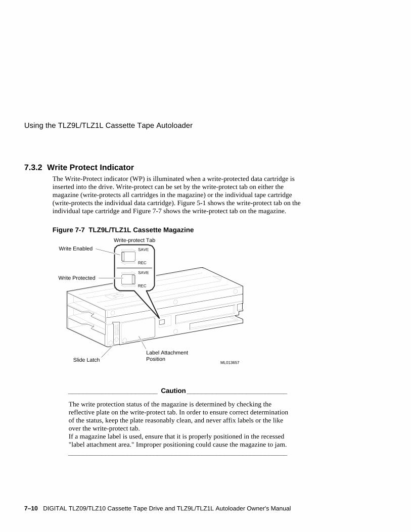
7.3.2 Write Protect IndicatorThe Write-Protect indicator (WP) is illuminated when a write-protected data cartridge isinserted into the drive. Write-protect can be set by the write-protect tab on either themagazine (write-protects all cartridges in the magazine) or the individual tape cartridge(write-protects the individual data cartridge). Figure 5-1 shows the write-protect tab on theindividual tape cartridge and Figure 7-7 shows the write-protect tab on the magazine.
Figure 7-7 TLZ9L/TLZ1L Cassette Magazine
Slide LatchLabel AttachmentPosition
Write-protect Tab
SAVE
REC
SAVE
REC
Write Protected
Write Enabled
ML013657
________________________ Caution___________________________
The write protection status of the magazine is determined by checking thereflective plate on the write-protect tab. In order to ensure correct determinationof the status, keep the plate reasonably clean, and never affix labels or the likeover the write-protect tab.If a magazine label is used, ensure that it is properly positioned in the recessed"label attachment area." Improper positioning could cause the magazine to jam.___________________________________________________________

Using the TLZ9L/TLZ1L Cassette Tape Autoloader
DIGITAL TLZ09/TLZ10 Cassette Tape Drive and TLZ9L/TLZ1L Autoloader Owner's Manual 7–11
7.3.3 Error IndicatorThe error indicator is illuminated when certain errors occur. When this indicator is lit incombination with a number in the 7-segment display, a particular error can be indicated.Table 7-3 lists the error and numeric combinations with a description of what they indicatewhen lit.
Table 7-3 Error Indications
Indicator and Number Error Message
1 Loader mechanism error. Call service personnel.
2 Embedded drive error. Call service personnel.
3 Media error. Replace tape cartridge.
4 Cartridge stuck in the drive. Call service personnel.
7.3.4 7-Segment Numeric DisplayThe 7-segment display normally displays the number of the data cartridge that is currentlyloaded in the drive.
When the Select button is pushed, this 7-segment display shows the number of thecartridge that has been selected. After 5 seconds, the selected cartridge will be loaded intothe drive.
When either the Warning or Error indicators are lit, the 7-segment display indicates thespecific type of warning or error (see Table 7-2 and Table 7-3).

Using the TLZ9L/TLZ1L Cassette Tape Autoloader
7–12 DIGITAL TLZ09/TLZ10 Cassette Tape Drive and TLZ9L/TLZ1L Autoloader Owner's Manual
7.3.5 Cartridge Number IndicatorsThe eight boxes at the bottom of the LCD panel are individually lit to indicate which slotsin the magazine contain cartridges. The boxes will blink to indicate that a cartridge isbeing loaded. A box that is not lit indicates that a cartridge is not in that slot of themagazine (for example, the cartridge is loaded in the drive). The box will become lit againonce the cartridge is returned to that slot in the magazine.
7.4 TLZ1L Front Panel Buttons and LCD PanelThe following sections describe the buttons and LCD panel indicators that are on theTLZ1L autoloader front panel.
7.4.1 Select and Enter ButtonsThe Select button, along with the Enter button on the TLZ1L autoloader front panel,allows the selection of any of the cartridges present in the magazine, once the magazinehas been inserted into the loader. The selected slot/cartridge number will be displayed inthe alphanumeric display area of the LCD panel. For example, if a write protected DDS 3tape in slot 2 has been selected and loaded into the drive in a full magazine configuration,the example shown below will appear in the LCD. If the tape is not write protected, andthe loader is not in compression mode, the “WP” and “DC” icons will be turned off. TheSelect and Enter buttons also have some other functions, specifically related to certainLCD operations. These functions are described in Section 7.4.3.
Ready
Tape 2
DDS 3DC
WP8
1
5 6
3
7
4
1 56
3 74 8
WP DC
DDS 3
Ready
Tape 2

Using the TLZ9L/TLZ1L Cassette Tape Autoloader
DIGITAL TLZ09/TLZ10 Cassette Tape Drive and TLZ9L/TLZ1L Autoloader Owner's Manual 7–13
7.4.2 Eject ButtonThe Eject button is used to accomplish an unload of the magazine. When pressed, thedrive unloads any currently loaded cartridge, and the loader mechanism returns it to themagazine. The magazine is then ejected from the loader.
The Eject button can also be used to exit an LCD submenu as described in Section 7.4.3.2.
__________________________ Note _____________________________
The Eject button can be disabled by sending a SCSI PREVENT MEDIAREMOVAL command from the host.____________________________________________________________
7.4.3 TLZ1L LCD PanelThe liquid crystal display (LCD) panel on the TLZ1L autoloader contains two basic areas,the Icon area and the Alphanumeric Display area (see Figure 7-8). A menu choice allowsa horizontal or vertical orientation to be selected.
Figure 7-8 TLZ1L LCD Panel
Alphanumeric Display Area
Icon Area
Horizontal
Vertical
TLZ1L
Self Test
Complete
DDS 3
DC
WP8
1
5
2
6
3
7
4
1 5
2 6
3 7
84
WP DC
DDS 3
TLZ1L
Self Test
Complete

Using the TLZ9L/TLZ1L Cassette Tape Autoloader
7–14 DIGITAL TLZ09/TLZ10 Cassette Tape Drive and TLZ9L/TLZ1L Autoloader Owner's Manual
1 52 63 7
84
7.4.3.1 LCD Icon AreaThe icon area of the TLZ1L LCD panel contains several different icons, each relating to aunique function or status. These are illustrated, and described as follows:
This symbol will be illuminated when the TLZ1L is operating in datacompression mode. When compression is disabled, this symbol will beturned off.
This symbol will be illuminated when the TLZ1L is write-protected.This can be accomplished either by write protecting an individualcartridge, or cartridges, or by write protecting the entire magazine witha slide switch on the side of the magazine. See Section 7.3.2 for moredetails on write protecting the magazine.
This group of boxes with numbers in them represents each of the slotsof the magazine. When a particular box is illuminated, it indicates thata cartridge is present in the magazine in that slot number. When aparticular box is not illuminated, there is no cartridge in that slot of themagazine. When a certain cartridge is taken from the magazine, andloaded into the drive in the TLZ1L, the box associated with thatmagazine slot will be turned off until the tape is returned to that slotafter being ejected from the drive.
This multi-segmented symbol is a bar graph representing how muchtape is on the take up reel. When each of the segments is black, thetape is at BOM. When each of them is blank, the tape is at EOM. Thisgives a visual indication of how much tape is used at any given time.
This symbol represents a tape cartridge. It flashes during tapeloading/unloading. When tape motion is occurring the icon reels willmove periodically to simulate tape motion.
This symbol will show what format is supported by the tape cartridgepresently installed in the tape drive. It will indicate either DDS1,DDS2, or DDS3 depending on the tape cartridge installed.
WP
DC
DDS 3

Using the TLZ9L/TLZ1L Cassette Tape Autoloader
DIGITAL TLZ09/TLZ10 Cassette Tape Drive and TLZ9L/TLZ1L Autoloader Owner's Manual 7–15
7.4.3.2 LCD Alphanumeric Display AreaThe alphanumeric display area of the TLZ1L LCD panel is used to display a number ofdifferent status conditions, and error information. Text can be displayed in eitherhorizontal, or vertical orientation with right side down, or left side down to match theorientation of the TLZ1L. This display section supports up to 6 lines of text in menudisplay mode, or 4 lines of text in other modes (when icons are also displayed).
The following are several examples of the types of messages that may appear in thedisplay, along with an explanation of the meaning of the display. The first sectiondiscussed is the menu mode display.
This is the menu display. It is entered by pushing and holdingthe Select button for 5 seconds. The example shown here is forthe case where no magazine is present in the loader. If amagazine is present, the display will be the same except that the“Language” option will not be available. Once in the menudisplay, if no button is pushed within approximately 10 seconds,the display will revert back to what was in the display whenmenu mode was entered.
The menu display is only available in horizontal mode due tothe number of lines, and spaces per line it requires. Use theSelect button to select which option you want to enter. An “>”in the left column will move to the next selection with eachdepression of the Select button. Once chosen, push the Enterbutton to enter that option screen.
After entering any of the following submenu mode options and making, or simply viewingthe selection choices, the display will revert back to the main menu screen in a fewseconds. The Eject button can also be depressed during the display of a submenu selectionto quickly return to the main menu screen.
The Version screen displays the device name, SCSI ID, loaderfirmware revision, and the loader and embedded drive serialnumbers. S/NL indicates the loader serial number, while S/NDindicates the embedded drive serial number. Only the embeddeddrive serial number will be returned via the Inquiry commandserial number page (80h).
The Orientation screen displays three options; horizontal, rightside down, and left side down. This will affect the orientation ofthe display only. It has no bearing on any functional operationsof the loader. The Select button is used to select the desiredorientation, and the Enter button must be pushed to put thechoice into effect.
>Version Autoload Unload Contrast Orientation Language
TLZ1LSCSI ID#5Ver. 0000S/NL xxxxxxxS/ND xxxxxxx
Orientation
>Horizontal R-side down L-side down

Using the TLZ9L/TLZ1L Cassette Tape Autoloader
7–16 DIGITAL TLZ09/TLZ10 Cassette Tape Drive and TLZ9L/TLZ1L Autoloader Owner's Manual
The Language screen displays the options for English, French,German, and Spanish. Once again the Select button is used toselect the desired language, and the Enter button must be pushedto implement it.
NOTE: If a magazine is present in the TLZ1L, the Languageoption is not available. Magazine must be ejected to access thisoption.
The Contrast screen is used to vary the contrast of the display.Push the Select button to adjust the contrast. The bar graph atthe bottom of the display will reflect the degree of contrast.
The Auto Load screen gives you the option of enabling, ordisabling the autoload feature. With autoload enabled, the firsttape in the magazine will be automatically loaded into the driveafter magazine insertion/scanning has taken place. Withautoload disabled, the loader will come ready after magazineinsertion/scanning is complete, with no tape having been loadedinto the drive. Push the Select button to choose ON or OFF, thenpush the Enter button to put the selection into effect. SeeSection 7.5.3.8 for further details on autoload operation.
The Unload Continuous screen is used to display the status ofthe continuous loop diagnostic feature of the loader. Whenenabled, the first tape in the magazine will be loaded into thedrive after the last tape in the magazine has been unloaded.When disabled (default) the loader will go idle after the last tapein the magazine has been unloaded from the drive and placedback in the magazine. The enabled position is used fordiagnostic exerciser testing only. Care should be taken not toenable it inadvertently as user data could be overwritten.
Language
>English French German Spanish
ContrastAdjustment
Auto Load
>OFF ON
UnloadContinuous
>OFF ON

Using the TLZ9L/TLZ1L Cassette Tape Autoloader
DIGITAL TLZ09/TLZ10 Cassette Tape Drive and TLZ9L/TLZ1L Autoloader Owner's Manual 7–17
The alphanumeric display area of the TLZ1L LCD panel is also capable of displayingseveral messages that indicate a certain operational status. Examples of these types ofmessages are shown below:
This will be displayed upon successful completion of the TLZ1Lselftest. Selftest will be executed upon power cycle sequence,after a hard reset, after firmware upgrade, or as a result of SendDiagnostic command with appropriate option bits set forselftest.
This message is displayed after the “TLZ1L SelfTest Complete”message has been displayed, and there is no magazine present inthe loader.
This message is displayed after insertion of a magazine into theloader, until the cartridge scanning process begins.
These messages will be displayed during the time the loader isscanning the cartridges in the magazine. After each slot is foundto contain a cartridge, it will change from “Scan X” to“ScanX OK”, and continue on to the next sequential slot untilall slots have been scanned. As each slot is found to contain acartridge, its slot box icon will also be illuminated.
Once all slots have been scanned successfully, the scanmessages will be turned off, and “Ready” will appear in thedisplay. The slot box icons will remain lit for each slot thatcontains a tape cartridge.
This message will be displayed when magazine ejection is inprogress. This is true in the case of manual ejection from thefront panel Eject button, or as a result of a SCSI command thatcauses magazine ejection (i.e. Unload to lun 1).
NoMagazine
TLZ1LSelfTestComplete
MagazineLoading
Scan1 OKScan2 OKScan3 OKScan 4
Ready
EjectingMagazine

Using the TLZ9L/TLZ1L Cassette Tape Autoloader
7–18 DIGITAL TLZ09/TLZ10 Cassette Tape Drive and TLZ9L/TLZ1L Autoloader Owner's Manual
This message is displayed whenever the Emergency Ejectprocedure is executed (see Section 7.5.3.6 for details).
Once a magazine is inserted, and the loader is not in autoloadmode and has completed scanning and come to the Ready state,a cartridge can be manually selected via the front panel Selectbutton. For each depression of the Select button, thecartridge/slot number will be incremented by one. The display atthe left shows the user selecting slot 3. After two seconds, theflashing “Push ENT” indication will be displayed. If the Selectbutton is pushed again while the “Push ENT” indication isflashing, it will turn off, and the display will show the nextsequential slot has been selected. Once the desired slot has beenselected, the Enter button must be pushed in order to confirmthe selection of the indicated cartridge. If the Enter button is notpushed, the selected cartridge will not be loaded into the drive,and the display will revert back to Ready.
NOTE: The Enter button must be depressed for a minimum of½ second, or the cartridge loading process will not be initiated.
Once the Enter button has been pushed for at least a ½ second,the loader will begin to load the selected tape into the drive.Providing there is no tape presently loaded in the drive, thedisplay will resemble the one shown at left. In this example, the#3 icon box will flash, during the load process for tape #3.
Once tape 3 is loaded into the drive, its slot box icon will beextinguished to show that slot is now vacant in the magazine,and the display will be changed to indicate the loader is nowready as shown here. This Ready Tape X message will bedisplayed any time a tape is loaded in the drive, and the loaderis ready to accept commands.
If a tape is already loaded in the drive when you select anothertape to be loaded, the display sequence is slightly different. If,for example, tape number 1 is already loaded in the drive whentape number 3 is selected to be loaded, the display will indicatethat tape 3 is selected, but that tape 1 is being unloaded. Onceunloaded and put back in the magazine, the tape 1 icon box willbe illuminated again (it would have been turned off while tape 1was loaded in the drive). The display will then change to the oneabove showing that tape 3 is being loaded, and proceed asdescribed above.
Select 3LoadTape 3
Select 3UnloadTape 1
Select 3
Push ENT
ReadyTape 3
EmergMagazineEject

Using the TLZ9L/TLZ1L Cassette Tape Autoloader
DIGITAL TLZ09/TLZ10 Cassette Tape Drive and TLZ9L/TLZ1L Autoloader Owner's Manual 7–19
This indication will slowly flash in the display if the loader isrequesting a cleaning cycle be executed. This indication willremain in the display until a cleaning cycle is successfullycompleted. It may be temporarily overridden by anothermessage in the display from time to time, but will always endup being displayed during any idle time until a successfulcleaning is accomplished.
When a cleaning cycle is being executed, the display willindicate that the cleaning is in process by flashing the CleaningIn Process indication in the LCD.
When the cleaning cartridge reaches EOM, no cleaning will beaccomplished. When this happens in single cartridge mode, themagazine will autoeject, and the display will indicate that thecleaning tape is at EOM by displaying the Cleaning Tape atEOM message. A few seconds later, the LCD will display aslowly flashing CleanReq message. Both messages will remainin the display until after a new cleaning tape is installed in themagazine and reinserted. The Cleaning Tape at EOM indicationwill change to Cleaning in Process. Once cleaning is successful,the CleanReq indication will be turned off. In 7/8 cartridgemode, the magazine will not autoeject, otherwise operation isthe same.
When a cartridge in the magazine is found to be misoriented,the display will alert the user that there is an illegal cassetteconfiguration, and eject the magazine. The slot icon for themisoriented tape will be illuminated. The magazine will beejected with tapes in the position they were in when the illegalcassette configuration was detected. The loader will not attemptto put the cartridges back into their original locations due to thepossibility that jamming could occur. The illegally orientedcartridge will be in slot 7 of the magazine when ejected.
If the magazine is found to be configured illegally (i.e.configured with no tape in slot 8, and at least one empty slot forslots 1 through 7), the LCD will inform the user of this, and themagazine will be ejected. If there is a tape in slot 8, and thereare any other empty slots in the magazine, the loader will revertto single tape mode. See Section 7.5.3 for further configurationdetails.
If a tape gets jammed inside of the drive for some reason, thedisplay will inform the user that a cassette is stuck in the drive.When this happens, you may, or may not be able to eject thetape from the drive. If a normal ejection can not be done, trydoing the emergency eject procedure (see Section 7.5.3.6 fordetails).
CleanReq
CleaningInProcess
CassetteStuckin Drive
CleaningTapeat EOM
IllegalCassetteConfig
IllegalMagazineConfig

Using the TLZ9L/TLZ1L Cassette Tape Autoloader
7–20 DIGITAL TLZ09/TLZ10 Cassette Tape Drive and TLZ9L/TLZ1L Autoloader Owner's Manual
The display will also show commands as they are issued to the TLZ1L. Several examplesof this type of display are illustrated below:
For the Move Medium command, the display will show thecommand and will also show the direction of the move. In theexample shown here, the Move Medium command is to movethe tape from slot one into the drive.
Once loaded in the drive, if another Move Medium command isissued to move the tape from the drive back into the magazine,the display will show this as well as shown in this example.
Other commands in general will be displayed in the formatshown here. This example shows the display for a Readcommand of tape 1. A similar display will be shown for Verify,Write, Erase, Rewind, Locate, Space, Unload, and Loadcommands.
This type of display is also supported for commands thatinvolve medium, or magazine movement. This example showsthe display for an Initialize Element Status command.
If a prevent media removal is in effect to either lun 0 or lun 1,and you attempt to eject the magazine via pushing the ejectbutton, the display will notify you of this via the display shownhere. Similarly, if you attempt to select a tape in the magazineto be loaded into the drive, and a prevent media removal is ineffect to lun 0, the display will show Select Prevent.
MoveMedium1 => Drv
EjectPrevent
ReadTape 1
MoveMedium1 => Mag
InitElementStatus

Using the TLZ9L/TLZ1L Cassette Tape Autoloader
DIGITAL TLZ09/TLZ10 Cassette Tape Drive and TLZ9L/TLZ1L Autoloader Owner's Manual 7–21
The LCD will also display messages related to error indications as shown in the followingexamples:
The display is also capable of displaying error information. Anexample of a Medium Error indication is given here. The toptwo lines display the error in text, while the bottom line displaysthe sense status bytes (sense key, asc, ascq, runtime code).
Similarly, for an embedded drive hardware error, the displaywill show the nature of the error in text followed by the sensedata on the bottom line.
The display for a loader hardware error is slightly different inthat the third line in the display will have either code bytespertaining to the error such as shown here, or another line oftext relating to the error, such as “ResetReq”, or other text. IfResetReq is displayed, try issuing a reset to recover from theerror.
7.5 TLZ9L/TLZ1L OperationThe TLZ9L/TLZ1L cassette tape autoloader can operate in two ways; automatically ormanually. It can also be operated in two modes; sequential or random access.
_________________________Caution ___________________________
Never transport the autoloader with a magazine installed. Damage to the tapes,autoloader, or magazine may result due to movement of the magazine. Data lossmay occur if a tape is loaded in the drive. Always unload the magazine prior totransporting the autoloader.____________________________________________________________
7.5.1 Automatic OperationsDuring automatic operations, the autoloader can function in sequential and random accessmodes at the same time.
In sequential mode, upon receipt of a SCSI unload command, the autoloader unloads thecurrent cassette and automatically cycles to the next cassette in the magazine. It continuesto unload and cycle to the next cassette until the last cassette has been unloaded. When this
Ldr HWErrorm3s02s0304xxxxxx
MediumError
03xxxxxx
Drv HWError
04xxxxxx

Using the TLZ9L/TLZ1L Cassette Tape Autoloader
7–22 DIGITAL TLZ09/TLZ10 Cassette Tape Drive and TLZ9L/TLZ1L Autoloader Owner's Manual
process is complete, the magazine stops to prevent accidental overwrite of data unless thecontinuous cycle switch (see Section 7.6.1 and Figure 7-2) is set. When the magazinestops, it may then be unloaded.
In random access mode, the autoloader responds to all of the SCSI random accesscommands.
7.5.2 Manual OperationsManual operations are performed from the front panel of the autoloader..
To load a magazine, simply insert the magazine into the magazine door (see Figure 7-13).Once the magazine has been inserted part way, the mechanism will pull it into theautoloader automatically. If there is already a magazine in the autoloader, it must first beejected by pressing the Eject button on the front panel. This ejects any cartridge in thedrive and then ejects the magazine. Once the magazine is inserted, the autoloader scans themagazine checking each slot for the presence of a cartridge and verifying proper cartridgeorientation. This scanning process can take up to 90 seconds.
To load a cartridge into the drive with the TLZ9L, press the Select button on the frontpanel until the desired cartridge/slot number is indicated in the 7-segment display. Theautoloader delays loading a cartridge for 5 seconds to give the user time to cycle to anothercartridge if desired. If a cartridge is already loaded in the drive, the autoloader will unloadthat cartridge, place it back in the magazine, and then load the selected cartridge. With theTLZ1L, the Enter button needs to be pushed when the desired cartridge is selected and theLCD displays “Push ENT”.

Using the TLZ9L/TLZ1L Cassette Tape Autoloader
DIGITAL TLZ09/TLZ10 Cassette Tape Drive and TLZ9L/TLZ1L Autoloader Owner's Manual 7–23
7.5.3 Magazine OperationsThe autoloader supports three basic magazine configurations. These configurations are 8,7, and single-cartridge modes. Any other number of cartridges is not supported and willeither cause the magazine to eject or put the autoloader into single-cartridge mode (if acartridge is in slot eight). See Section 7.5.3.4 for the procedure on loading cartridges intothe magazine and Section 7.5.3.7 for the procedure on unloading cartridges from themagazine.
7.5.3.1 Eight Cartridge ModeIn eight cartridge mode the magazine accommodates either eight data cartridges or sevendata cartridges and one cleaning cartridge. The sequence in which the cartridges areinserted into the magazine determines the numbers by which they are managed asindicated in Figure 7-9. The letter C indicates the cleaning cartridge for the TLZ9L. If acleaning cartridge is not used, the C slot can be populated with the eighth data cartridge toprovide the highest capacity per magazine..
Figure 7-9 Eight Cartridge Mode
7
C
1
6
2
5
4
3
ML013658
8or

Using the TLZ9L/TLZ1L Cassette Tape Autoloader
7–24 DIGITAL TLZ09/TLZ10 Cassette Tape Drive and TLZ9L/TLZ1L Autoloader Owner's Manual
7.5.3.2 Seven Cartridge ModeIn seven cartridge mode the C or 8 slot is left vacant as shown in Figure 7-10. When themagazine is inserted into the autoloader, this slot is not available for use by the autoloader.Any attempt to access this slot will generate an error..
Figure 7-10 Seven Cartridge Mode
7
1
6
2
5
4
3
ML013659
C or 8
7.5.3.3 Single Cartridge ModeIn single cartridge mode, either a data cartridge or a cleaning cartridge is inserted into theC or 8 slot position of the magazine as shown in Figure 7-11.
Figure 7-11 Single Cartridge Mode
ML013660
C 8or

Using the TLZ9L/TLZ1L Cassette Tape Autoloader
DIGITAL TLZ09/TLZ10 Cassette Tape Drive and TLZ9L/TLZ1L Autoloader Owner's Manual 7–25
7.5.3.4 Loading Cartridges Into the MagazineWhen loading data cartridges into the magazine, the bottom shelf of the magazine shouldbe loaded first. Ensure that the cartridges are oriented correctly as shown in Figure 7-12.Load cartridge 3 in the bottom shelf first, followed by cartridge 2 and then cartridge 1 inthat order. It is highly recommended that you number each cartridge by placing anumbered label on the cartridges in order to keep track of each cartridge.
After loading the bottom shelf, start loading the top shelf of the magazine beginning withcartridge 4 and proceeding with cartridge 5, cartridge 6, and cartridge 7 in that order.
If either an 8th data cartridge or a cleaning cartridge is to be used, load it into middle shelfof the magazine..
Figure 7-12 Loading Cartridges Into the Magazine
ML013661

Using the TLZ9L/TLZ1L Cassette Tape Autoloader
7–26 DIGITAL TLZ09/TLZ10 Cassette Tape Drive and TLZ9L/TLZ1L Autoloader Owner's Manual
7.5.3.5 Loading the Magazine Into the AutoloaderTo load a magazine into the autoloader, first apply power to the autoloader by powering onthe system for an embedded autoloader, or by pressing the power switch on the tabletopautoloader. The BUSY and TAPE LED indicators blink as a self-test is performed. Whenthe BUSY and TAPE LED indicators stop blinking on the TLZ9L or when the “SelfTestComplete” message is displayed on the TLZ1L, the magazine can be inserted into theautoloader as shown in Figure 7-13. When the magazine is inserted, the TAPE LEDindicator lights on the TLZ9L or the “Magazine Loading” message is displayed on theTLZ1L. If the magazine is write-protected, the write-protect (WP) indicator also lights.
Once the magazine is inserted, the autoloader will cycle through and count the cartridgesin the magazine. If any of the cartridges are misoriented, or if the number of cartridgespresent is other than 1, 7, or 8 with slot 8 empty, the magazine will be ejected. At the endof this initialization, if all of the cartridges are oriented correctly and the correct number ofcartridges are present, the autoloader goes to the idle state unless autoload mode is enabled(see Section 7.5.3.8). A cartridge can then be selected and loaded into the drive eithermanually or through software control.
Figure 7-13 Loading the Magazine Into the Autoloader
POWER
BUSY
TAPE
EJECT
SELECT
ML013662
__________________________ Note ____________________________
The TLZ9L is shown in the figure, but the operation also applies to the TLZ1L.___________________________________________________________
Using the TLZ9L/TLZ1L Cassette Tape Autoloader
DIGITAL TLZ09/TLZ10 Cassette Tape Drive and TLZ9L/TLZ1L Autoloader Owner's Manual 7–27
7.5.3.6 Ejecting the MagazineUnder normal conditions, the magazine can be ejected by simply pressing the Eject buttonon the front panel. Any cartridge that may be in the drive at the time the Eject button ispressed will be rewound and unloaded back into the magazine. The cartridges are thenmoved to their original locations within the magazine and the magazine is ejected.
If the autoloader encounters a certain type of fatal error, you may not be able to eject themagazine in a normal manner. However, you still may be able to eject the magazine usingan emergency eject. To invoke the emergency eject, press and hold the Eject button for tenseconds while the error indication is displayed in the 7-segment display of the TLZ9L orwhile the error information is displayed on the TLZ1L LCD panel. If a cartridge is stuck inthe drive, the magazine will be ejected without this cartridge being present. The TLZ9LLCD panel will then indicate an error code of 4 while the TLZ1L LCD panel will display a“Cassette Stuck in Drive” message and service personnel will need to be called.

Using the TLZ9L/TLZ1L Cassette Tape Autoloader
7–28 DIGITAL TLZ09/TLZ10 Cassette Tape Drive and TLZ9L/TLZ1L Autoloader Owner's Manual
7.5.3.7 Unloading Cartridges From the MagazineWhen unloading cartridges from a magazine, it is recommended that the magazine be heldover a table or bench so that the cartridges will fall gently to the table top and not fall onthe floor where they could be damaged..
Perform the unloading process by pressing down on the magazine slide latch with thethumb of your left hand and then placing the finger of your right hand in the hole at therear of the magazine and pushing the cartridges toward the front of the magazine (seeFigure 7-14). Continue pushing the cartridges all the way to the front of the magazine byusing the slot in the bottom of the magazine. This should remove the first five cartridgesfrom the magazine.
Next, orient the magazine with the open end pointing upward and gently tap the magazineagainst the palm of your hand. This moves the remaining cartridges to the bottom shelfwhere they can be removed by following the same procedure used for removing the firstfive cartridges.
Finally, the cartridge in the middle shelf can be removed by grasping it with your thumband index finger and pulling it out of the magazine while continuing to press down on themagazine slide latch.
Figure 7-14 Unloading Cartridges From the Magazine
ML013663

Using the TLZ9L/TLZ1L Cassette Tape Autoloader
DIGITAL TLZ09/TLZ10 Cassette Tape Drive and TLZ9L/TLZ1L Autoloader Owner's Manual 7–29
7.5.3.8 Autoload FunctionFor the TLZ9L, switch four on the embedded drive within the autoloader controls theautoload function (see Figure 7-2 and Table 3-2). When this switch is in the ON position,autoload is enabled. For the TLZ9L revision A01, this switch only controls autoload for 7or 8 cartridge mode. In single tape mode, the tape in the magazine will always beautomatically loaded regardless of the position of this switch.
Beginning with TLZ9L revision A02, if the autoload switch is in the OFF position, no tapewill be automatically loaded after magazine insertion in 8, 7, or single cartridge mode. Ifthe switch is in the ON position, the first tape will be automatically loaded in 8, 7, orsingle cartridge mode.
For the TLZ1L, the LCD menu mode provides control for the autoload function (seeSection 7.4.3.2).
7.6 Switch SettingsThe following sections describe the switchpack settings on the autoloader and the SCSI IDselect switch on the tabletop autoloader. It should be noted that all of the drive switchesand jumpers still function as documented in Chapter 3 for the drive mounted internal to theautoloader except where noted otherwise. For example, to enable MRS detection on theautoloader, place drive switch S2 to the ON position (see Section 3.3.3 and Figure 3-2).
7.6.1 Switchpack SettingsThere are two switchpacks on the TLZ9L autoloader. One is on the autoloader and theother is on the embedded drive. The TLZ1L autoloader does not have the autoloaderswitchpack, since those options are provided by the LCD panel menus (see Section7.4.3.2). The TLZ9L autoloader switchpack contains four switches and is located on thebottom of the autoloader toward the front (see Figure 7-2). It is accessible through a cutoutin the sheet metal chassis. If the autoloader is configured as a -VA, a cosmetic panelcovering a portion of the cutout will need to be removed by removing two screws. For thetabletop version, access to this switchpack can be gained by removing the front bezel. Thetop cover will have to be removed in order to remove the front bezel.

Using the TLZ9L/TLZ1L Cassette Tape Autoloader
7–30 DIGITAL TLZ09/TLZ10 Cassette Tape Drive and TLZ9L/TLZ1L Autoloader Owner's Manual
Table 7-4 lists the four TLZ9L switches, their default settings, and the function of each.The default setting for all four switches is the ON position.
Table 7-4 TLZ9L Autoloader Switchpack Settings
Switch Default Function
SW1 ON Reserved
SW2 ON Reserved
SW3 ON Reserved
SW4 ON Continuous cycle mode disabled. OFF for enabled.
________________________ Caution___________________________
Enabling continuous cycle mode (SW4 OFF) may overwrite existing data. Thisfeature is used for diagnostic purposes only.___________________________________________________________
7.6.2 SCSI ID Select Switch (Tabletop Only)The SCSI ID select switch is located on the rear panel of the tabletop autoloader (seeFigure 7-4 or Figure 7-5). The SCSI ID is set by pressing the + or - button until the desiredaddress is displayed. ..
7.7 Cleaning RequirementsA cleaning tape preventive maintenance program is required. Head cleaning shall be theonly preventive maintenance required and shall be accomplished with a tape cleaningcartridge. The DIGITAL part number for the cleaning cartridge is TLZ04-HA. A cleaningcycle should be performed at the following times:
• After every 24 hours of tape use
• When a cleaning cycle is requested by way of a message on the LCD of the operatorfront panel (see Table 7-2 for the TLZ9L and Section 7.4.3.2 for the TLZ1L), theTLZ9L displays a “wrench 1”, while the TLZ1L displays a “CleanReq” message.
__________________________ Note ____________________________
If the cleaning request appears frequently for a particular cartridge, it isrecommended that the cartridge be replaced. Also see Section 6.2.___________________________________________________________

Using the TLZ9L/TLZ1L Cassette Tape Autoloader
DIGITAL TLZ09/TLZ10 Cassette Tape Drive and TLZ9L/TLZ1L Autoloader Owner's Manual 7–31
There are basically four methods of accomplishing a cleaning cycle for theTLZ9L/TLZ1L.
Manual: • Place single cleaning cartridge into slot 8 of magazine (other slotsare empty).
• Insert the magazine into the autoloader.
• If the autoload function is disabled (default), you will need topush the Select button to select slot 8. For the TLZ9L, after 5seconds, the cleaning tape will be loaded into the drive and acleaning cycle will be executed. For the TLZ1L, the Enter buttonwill need to be pushed when prompted. After successful cleaning,the cartridge will be returned to the magazine and the magazinewill be ejected from the autoloader.
• If the autoload function is enabled, the autoloader willautomatically load the cartridge into the drive, execute thecleaning cycle, then return the cartridge to the magazine, and ejectthe magazine.
Sequential Mode: • Place the cleaning cartridge into any magazine slot along withdata cartridges appropriate for the mode of operation (i.e. 7cartridge mode, or 8 cartridge mode).
• Insert the magazine into the autoloader.
• Use the select button for the TLZ9L or the select button then theenter button for the TLZ1L to select the slot with the cleaningcartridge.
• Autoloader will load the cartridge into the drive, execute thecleaning cycle, then return the cartridge to the magazine.
• If you then press the select button once, it will select the nextsequential data cartridge after the data cartridge that was loadedinto the drive last. (i.e. If you had cartridge 3 loaded, then pushedthe select button to select and load the cleaning cartridge from itsslot, the next time you push the select button after the cleaningcycle has completed, it will load cartridge 4.).
Sequential BackupMode:
• Place the cleaning cartridge into any magazine slot along withdata cartridges.
• Execute sequential backup via chosen software utility.
• When EOD is reached and reported to host, host will issueUNLOAD command for each cartridge. This will cause the nextsequential cartridge to be automatically loaded into the drive. Ifthis is a cleaning cartridge, a cleaning cycle will be executed andthe cleaning cartridge will automatically be put back into themagazine. The next cartridge will then be automatically loadedinto the drive to continue backup operation.
Random Mode: • Host sends the MOVE MEDIUM command to move the cleaningcartridge from the magazine to the drive.

SES Template Word 7 Blank Page Fix by Peter LaQuerre

DIGITAL TLZ09/TLZ10 Cassette Tape Drive and TLZ9L/TLZ1L Autoloader Owner's Manual A–1
A Cassette Tape Drive and Autoloader
Specifications
The following tables list the TLZ09 and TLZ10 cassette tape drive specifications.
Table A-1 TLZ09/TLZ10 Cassette Tape Drive Specifications
Characteristic Specification(s)
Mode of operation Streaming, and start/stop
Drive interface Small Computer System Interconnect (SCSI-2)
Dimensions See Table A-2
Supported Media (read/write) DDS-1, 1.3 GB/ 2.6 GB, 4 mm x 60 m (TLZ04-CA)
DDS-1, 2.0 GB/4.0 GB, 4 mm x 90 m (TLZ06-CA)
DDS-2, 4.0 GB/8.0 GB, 4 mm x 120 m (TLZ07-CA)
DDS-3, 12 GB/24 GB, 4 mm x 125 m (TLZ10-CA, TLZ10only)
Bit density 114 Mbits per square inch (DDS-1)
171 Mbits per square inch (DDS-2)
341 Mbits per square inch (DDS-3) (TLZ10 only)
Transfer rate (typical) 778 Kbyte/s noncompression (DDS-2) (TLZ09)
1556 Kbyte/s compression (DDS-2) (TLZ09)
1.18 Mbyte/s noncompression (DDS-3) (TLZ10)
2.36 Mbyte/s compression (DDS-3) (TLZ10)
Recording format Digital data storage (DDS-3 for TLZ10 only, DDS-2, DDS-DC, DDS-1)

Cassette Tape Drive and Autoloader Specifications
A–2 DIGITAL TLZ09/TLZ10 Cassette Tape Drive and TLZ9L/TLZ1L Autoloader Owner's Manual
Table A-1 (Cont.) TLZ09/TLZ10 Cassette Tape Drive Specifications
Characteristic Specification(s)
Cassette capacity (typical) 4 Gbytes with 120 meter tape in native mode
8 Gbytes (typical) with 120 meter tape and data compression
12 Gbytes with 125 meter tape in native mode (TLZ10 only)
24 Gbytes (typical) with 125 meter tape and datacompression (TLZ10 only)
Operating temperature1 5°C to 45°C (41°F to 113°F) for DDS-1 and DDS-2
15°C to 55°C (59°F to 131°F) for DDS-3
Nonoperating temperature -40°C to 70°C (-40°F to 158°F)
Operating humidity1 20% to 80% RH maximum, noncondensing, maximum wetbulb temperature 26°C (79°F) for DDS-1 and DDS-2
10% to 80% RH maximum, noncondensing, maximum wetbulb temperature 26°C (79°F) for DDS-3
Nonoperating humidity 5% to 95% RH maximum, noncondensing
Operating altitude 0 to 4.6 km (0 to 15,000 ft)
Nonoperating altitude 0 to 4.9 km (0 to 16,000 ft) (TLZ09)
0 to 12.2 km (0 to 40,000 ft) (TLZ10)
Internal SCSI cable length(TLZ09/TLZ10 tabletop)
145 mm
Passes per cassette tape 2000
Power consumption (average)
Tabletop 22 W
Drive 7.4 W
Power requirements (typical)
Tabletop (TLZ09/TLZ10) 100 to 240 V ac, 0.3 A
3.5 Inch Drive +5 V dc, 1.5 A (TLZ09), 1.0 A (TLZ10)
5.25 Inch Drive +12 V dc, 0.2 A (TLZ09), 0.21 A (TLZ10)1 These values are media dependent.

Cassette Tape Drive and Autoloader Specifications
DIGITAL TLZ09/TLZ10 Cassette Tape Drive and TLZ9L/TLZ1L Autoloader Owner's Manual A–3
Table A-2 TLZ09/TLZ10 Cassette Tape Drive Dimensions
Dimensions 3.5 Inch Drive 5.25 Inch Drive Tabletop
Height 41.2 mm (1.6 in) 41.2 mm (1.6 in) 52.4 mm (2.07 in)
Width 101.6 mm (4.0 in) 146 mm (5.7 in) 160 mm (6.3 in)
Length 146 mm (5.7 in) 146 mm (5.7 in) 300 mm (11.8 in)
Weight 0.66 kg (1.5 lb) (TLZ09) 0.91 kg (2.0 lb) (TLZ09) 2.2 kg (4.85 lb)
0.62 kg (1.4 lb) (TLZ10) 0.87 kg (1.9 lb) (TLZ10)
Table A-3 TLZ09/TLZ10 Tabletop Noise Declaration
Acoustics - declared values per ISO 9296 and ISO 7779:
LwAd LpAm (bystander positions)
Idle 4.8 B 39 dBA
Operating 4.9 B 40 dBA
Schallemissionswerte - Werteangaben nach ISO 9296 und ISO 7779/DIN EN27779:
LwAd LpAm (Zuschauerpositionen)
Leerlauf 4,8 B 39 dBA
Betrieb 4,9 B 40 dBA)
__________________________ Note _____________________________
Current values for specific configurations are available from DIGITALrepresentatives. 1 B = 10 dBA.Aktuelle Werte für spezielle Ausrüstungsstufen sind über die Digital EquipmentVertretungen erhältlich. 1 B = 10 dBA.____________________________________________________________

Cassette Tape Drive and Autoloader Specifications
A–4 DIGITAL TLZ09/TLZ10 Cassette Tape Drive and TLZ9L/TLZ1L Autoloader Owner's Manual
The following tables list the TLZ9L/TLZ1L cassette tape autoloader specifications.
Table A-4 TLZ9L/TLZ1L Cassette Tape Autoloader Specifications
Characteristic Specification(s)
Mode of operation Streaming, and start/stop
Drive interface Small Computer System Interconnect (SCSI-2)
Dimensions See Table A-5
Supported Media (read/write) DDS-1, 1.3 GB/ 2.6 GB, 4 mm x 60 m (TLZ04-CA)
DDS-1, 2.0 GB/4.0 GB, 4 mm x 90 m (TLZ06-CA)
DDS-2, 4.0 GB/8.0 GB, 4 mm x 120 m (TLZ07-CA)
DDS-3, 12 GB/24 GB, 4 mm x 125 m (TLZ10-CA, TLZ1Lonly)
Bit density 114 Mbits per square inch (DDS-1)
171 Mbits per square inch (DDS-2)
341 Mbits per square inch (DDS-3) (TLZ1L only)
Transfer rate (typical) 778 Kbyte/s noncompression (DDS-2) (TLZ9L)
1556 Kbyte/s compression (DDS-2) (TLZ9L)
1.18 Mbyte/s noncompression (DDS-3) (TLZ1L)
2.36 Mbyte/s compression (DDS-3) (TLZ1L)
Recording format Digital data storage (DDS-3 for TLZ1L only, DDS-2, DDS-DC, DDS-1)
Cassette capacity (typical) 4 Gbytes with 120 meter tape in native mode
8 Gbytes (typical) with 120 meter tape and data compression
12 Gbytes with 125 meter tape in native mode (TLZ1L only)
24 Gbytes (typical) with 125 meter tape and datacompression (TLZ1L only)
Magazine capacity 32 gigabytes with 120 meter tape in native mode
64 gigabytes (typical) with 120 meter tape and datacompression
96 gigabytes with 125 meter tape in native mode (TLZ1Lonly)
192 gigabytes (typical) with 125 meter tape and datacompression (TLZ1L only)

Cassette Tape Drive and Autoloader Specifications
DIGITAL TLZ09/TLZ10 Cassette Tape Drive and TLZ9L/TLZ1L Autoloader Owner's Manual A–5
Table A-4 (Cont.) TLZ9L/TLZ1L Cassette Tape Autoloader Specifications
Characteristic Specification(s)
Operating temperature1 5°C to 45°C (41°F to 113°F) for DDS-1 and DDS-2
15°C to 55°C (59°F to 131°F) for DDS-3
Nonoperating temperature -40°C to 70°C (-40°F to 158°F)
Operating humidity1 20% to 80% RH maximum, noncondensing, maximum wetbulb temperature 26°C (79°F) for DDS-1 and DDS-2
10% to 80% RH maximum, noncondensing, maximum wetbulb temperature 26°C (79°F) for DDS-3
Nonoperating humidity 5% to 95% RH maximum, noncondensing
Operating altitude 0 to 4.6 km (0 to 15,000 ft)
Nonoperating altitude 0 to 4.9 km (0 to 16,000 ft) (TLZ9L)
0 to 12.2 km (0 to 40,000 ft) (TLZ1L)
Internal SCSI cable length(tabletop)
145 mm
Passes per cassette tape 2000
Power consumption (typical,write mode)
Tabletop 30 W
Embedded 8.4 W (TLZ9L), 10.1 W (TLZ1L)
Power requirements (typical)
Tabletop (-DB) 100 V ac, 0.3 A
240 V ac, 0.14 A
Embedded (-AA) +5 V dc, 1.2 A (TLZ9L), 1.3 A (TLZ1L)
Embedded (-AA) +12 V dc, 0.2 A (TLZ9L), 0.3 A (TLZ1L)1 These values are media dependent.
Table A-5 TLZ9L/TLZ1L Cassette Tape Autoloader Dimensions
Dimensions -AA -DB
Height 82.5 mm (3.25 in) 109 mm (4.29 in)
Width 146.0 mm (5.75 in) 211 mm (8.31 in)
Length 241.6 mm (9.51 in) 296 mm (11.65 in)
Weight 2.4 kg (5.30 lb) 5.0 kg (11.0 lb)

Cassette Tape Drive and Autoloader Specifications
A–6 DIGITAL TLZ09/TLZ10 Cassette Tape Drive and TLZ9L/TLZ1L Autoloader Owner's Manual
Table A-6 TLZ9L-DB Noise Declaration
Acoustics - declared values per ISO 9296 and ISO 7779:
LwAd LpAm (bystander positions)
Idle 4.7 B 33 dBA
Operating 4.8 B 34 dBA
Schallemissionswerte - Werteangaben nach ISO 9296 und ISO 7779/DIN EN27779:
LwAd LpAm (Zuschauerpositionen)
Leerlauf 4,7 B 33 dBA
Betrieb 4,8 B 34 dBA)
Table A-7 DS-TLZ1L-DB Noise Declaration
Acoustics - declared values per ISO 9296 and ISO 7779:
LwAd LpAm (bystander positions)
Idle 4.6 B 30 dBA
Operating 4.8 B 32 dBA
Schallemissionswerte - Werteangaben nach ISO 9296 und ISO 7779/DIN EN27779:
LwAd LpAm (Zuschauerpositionen)
Leerlauf 4,6 B 30 dBA
Betrieb 4,8 B 32 dBA)
__________________________ Note ____________________________
Current values for specific configurations are available from DIGITALrepresentatives. 1 B = 10 dBA.Aktuelle Werte für spezielle Ausrüstungsstufen sind über die Digital EquipmentVertretungen erhältlich. 1 B = 10 dBA.___________________________________________________________

DIGITAL TLZ09/TLZ10 Cassette Tape Drive and TLZ9L/TLZ1L Autoloader Owner's Manual B–1
B Product Notes for DIGITAL UNIX,
OpenVMS, and Windows NT
DIGITAL UNIX TLZ09/TLZ9L/TLZ10/TLZ1L Compression andNoncompression Modes
The default mode for the TLZ09/TLZ9L/TLZ10/TLZ1L tape devices is for compressionenabled. For software control of compression, use the following commands. To use thedrive in compression mode, specify the device as:
/dev/rmt?h or /dev/rmt?m
To use the drive in noncompression mode, specify the device as:
/dev/rmt?1 or /dev/rmt?a
DIGITAL UNIX DUMP UtilityIt should be noted that the numbers returned by the DUMP utility are not accurate.However, use of the following parameters will ensure proper operation.
The parameters that should be used when running the DUMP utility on a DDS-2 tape incompressed and noncompressed mode are as follows:
Noncompressed Mode:
density = 61000 effective tape length (with 120 meter tape)size = 76586 (with 120 meter tape)Example: dump 0dsf 61000 76586 /dev/rmt?1 /dev/rrz0g

Product Notes for DIGITAL UNIX, OpenVMS, and Windows NT
B–2 DIGITAL TLZ09/TLZ10 Cassette Tape Drive and TLZ9L/TLZ1L Autoloader Owner's Manual
Compressed Mode:
density = 61000 effective tape length (with 120 meter tape)size = 76586 (with 120 meter tape) × compression (which, for most cases is 2)Example: dump 0dsf 61000 153172 /dev/rmt?h /dev/rrz0g
__________________________ Note ____________________________
You must type UNIX commands using lowercase characters. For DDS-3 (125meter tape), the size field should be multiplied by 3 in each of the previouscases (TLZ10/TLZ1L only).___________________________________________________________
OpenVMS TLZ09/TLZ9L/TLZ10/TLZ1L Compression andNoncompression Modes
The default mode for the TLZ09/TLZ9L/TLZ10/TLZ1L tape devices is for compressionmode. For software control of compression, use the following commands. To use the drivein compression mode, specify:
MEDIA_FORMAT=COMPACT software switch
To use the drive in noncompression mode, specify:
MEDIA_FORMAT=NOCOMPACT software switch
Examples for enabling/disabling compression are:
INIT/MEDIA_FORMAT=(NO)COMPACT MKx#:MOUNT/MEDIA_FORMAT=(NO)COMPACT MKx#:BACKUP/MEDIA_FORMAT=(NO)COMPACT MKx#:
__________________________ Note ____________________________
To be sure that the compression is enabled/disabled, you should include thecorrect software switch with each command line.___________________________________________________________
Windows NT TLZ09/TLZ9L/TLZ10/TLZ1L Compression andNoncompression Modes
Compression mode is enabled/disabled via drive configuration setup in Windows NT. Seeyour Windows NT documentation for more details.

Product Notes for DIGITAL UNIX, OpenVMS, and Windows NT
DIGITAL TLZ09/TLZ10 Cassette Tape Drive and TLZ9L/TLZ1L Autoloader Owner's Manual B–3
DIGITAL Operating System SupportTable B-1 lists the minimum operating system version for full support for theTLZ09/TLZ10 tape drives and the TLZ9L/TLZ1L cassette tape autoloaders.
Table B-1 Operating System Support
Minimum Operating System Version for Full Support
Device DIGITAL UNIX OpenVMS Windows NT
TLZ09 V3.2 V6.1-1H2 V3.51, V4.0 ServicePack5
TLZ9L V3.2G V6.2-1H3 V4.0 ServicePack2
TLZ10/TLZ1L V4.0A1 V6.2-1H3 V4.0 with DIGITAL supplied Windows NTdriver kit (PN QZ-012AA-UC) or downloadfrom DIGITAL web site(www.storage.digital.com) and follow the paththrough support and driver updates for tapes.The supplied driver works for both the TLZ10and the TLZ1L for Windows NT V4.0.
1 V3.2G and V4.0 provide full support with available patch kits.

SES Template Word 7 Blank Page Fix by Peter LaQuerre

DIGITAL TLZ09/TLZ10 Cassette Tape Drive and TLZ9L/TLZ1L Autoloader Owner's Manual C–1
C Product Notes for Non-DIGITAL Platforms
__________________________ Note _____________________________
Check DIGITAL’s storage web page for up-to-date information about supportfor non-DIGITAL platforms at: http://www.storage.digital.com
____________________________________________________________
Product Notes for Novell NetWare and Microsoft Windows NTThis section provides information for the system administrator who should read thismaterial before installing and using the TLZ09/TLZ10 DAT tape drives or TLZ9Lautoloader with a host system operating under the Novell NetWare or Microsoft WindowsNT operating systems.
Host SCSI InterfaceThe tape drive uses the standard SCSI-2 command set to interface to the PC-based hostsystem. The host system thus must be equipped with a SCSI adapter to properly interfacethe tape drive with the host. For example, the host SCSI adapter might interface thecomputer's PCI bus to the SCSI-2 port of the tape drive.
A host PC SCSI adapter is normally supplied with a compatible software driver for usewith its operating system. When operating under the Novell NetWare or the MicrosoftWindows NT operating systems, the software driver must be pre-loaded in accordancewith the SCSI adapter manufacturer's installation procedure to ensure a proper interfacebetween the tape drive and the host. In addition, a user-level tape read/write softwareprogram may be required to implement tape support under the NetWare or Windows NTenvironments. There are many commercial software products available that provide forhost or network-based data backup and restore, archiving, data logging, etc. for theseoperating systems.

Product Notes for Non-DIGITAL Platforms
C–2 DIGITAL TLZ09/TLZ10 Cassette Tape Drive and TLZ9L/TLZ1L Autoloader Owner's Manual
Before purchasing a user-level software product, ensure that the tape drive or tape loader issupported by that product. Commercial software vendors usually publish a supportedhardware list, or have telephone technical support personnel who will answer questionsregarding compatibility of a particular tape drive or other storage devices. When choosinga software product suitable for your application, follow the software vendor's installationprocedure to implement support for your tape drive.
The TLZ09 is supported only under Windows NT version 3.51 by adding the "4 millimeterSony drive" tape device option. Follow the Windows NT "Add/Remove Tape Devices"procedure to add this support. The TLZ10 is not supported under Windows NT version3.51.
The TLZ09 is supported only under Windows NT version 4.0 by adding the "4 millimeterDAT drive" tape device option. Follow the Windows NT "Tape Devices" procedure to addthis support. The TLZ10 is supported only under Windows NT version 4.0 by adding the"4 millimeter Sony drive" tape device option. Follow the Windows NT "Add/RemoveTape Devices" procedure to add this support.
The Novell NetWare operating system provides tape backup software called SBACKUPwhich will work with the product. Refer to the NetWare documentation for instructions onconfiguring this product and operating the SBACKUP utility.
_________________________ Notes____________________________
SBACKUP does not support autoloaders. You will need to use a commerciallyavailable backup software package for the TLZ9L autoloader.
Please check the Novell web page for TLZ10 support information.___________________________________________________________
Native tape support (that is, the tape support supplied in the operating system) forWindows NT or NetWare will support the functions of a single drive. Limited tape loadersupport (manual or sequential mode) is also provided as native support.

Product Notes for Non-DIGITAL Platforms
DIGITAL TLZ09/TLZ10 Cassette Tape Drive and TLZ9L/TLZ1L Autoloader Owner's Manual C–3
Product Notes for SunThis section describes how to include the TLZ09 and TLZ10 tape drive or TLZ9Lautoloader in a Sun SPARC system running Solaris™ 2.3 (or later) or SunOS™ 4.1.x. Theinformation covers configuration of the host system to communicate with the tape drive.
General Information
__________________________ Note _____________________________
This tape drive supports a variable block size and a small number of fixed blocksizes. Maximum performance is obtained by using the variable block size modewhenever possible. Selecting this mode is based on two variables in theconfiguration file (st_conf.c and st.conf) - "block size", which should be set to 0,and the "ST_VARIABLE" switch which must be OR'd with the other switches.Depending on your version of the Solaris operating system, you may not be ableto use the variable block size mode.
If your operating system version is:• SunOS 4.1.x or Solaris 2.3, set the block size in the tape configuration file
to 8192.• Solaris 2.4 or 2.5, set the block size in the tape configuration file to 0.
These recommendations are for use with system utilities. For third partysoftware, follow the recommendations of the manufacturer. Use the followingsteps to implement this information.____________________________________________________________
You must rebuild your kernel, with the parameters given, to ensure that your devicefunctions properly.
When using the dump utility under SunOS 4.1.x, you must supply the correct "d bpi"(density code) and "s size" tape length for dump to calculate the correct number of tapesrequired. The "b factor" (blocking factor) is of less importance, and we recommend a valueof 128 for that parameter.
Compression can be enabled/disabled at any time by selecting the appropriate device file.See the following sections on "st_conf.c" and "st.conf" for details on how we configuredensity codes.

Product Notes for Non-DIGITAL Platforms
C–4 DIGITAL TLZ09/TLZ10 Cassette Tape Drive and TLZ9L/TLZ1L Autoloader Owner's Manual
In general, the density code hex value 0xfd turns off compression and the code 0xfe turnsit on. Since four driver variations are created, a number of combinations are possible. Weconfigured our systems for two drivers without compression and two drivers withcompression; you may decide that some other combination is more suitable for yoursystem.
Modifications Required for SunOS 4.1.x
Installation Procedure
__________________________ Note ____________________________
In order to support the addition of this device, your system's/sys/scsi/targets/st_conf.c file must contain the applicable driveinformation. For additional information on this requirement, read the man pagesfor "st".___________________________________________________________
System ModificationPerform the following steps to modify the system for communication with the TLZ9Lautoloader (see notes at the end of this sub-section for TLZ09 and TLZ10 differences):
1. From the command line, type:
cd /sys/scsi/targets
2. Edit the "st_conf.c" file and carefully add the following structure before the "/* TLZ94mm 8GB */" entry:
/* Entry for DEC TLZ9L. DAT 4mm Helical Scan tape drive, /wCompression. */{ "DEC 8GB 4mm Helical Scan", 12, "DEC^^^^^TLZ9", ST_TYPE_DEFAULT, 8192, (ST_VARIABLE <VBAR> ST_BSF <VBAR> ST_BSR <VBAR> ST_LONG_ERASE <VBAR> ST_KNOWS_EOD), 5000, 5000, { 0xfd, 0xfd, 0xfe, 0xfe }, { 0, 0, 0, 0 }},

Product Notes for Non-DIGITAL Platforms
DIGITAL TLZ09/TLZ10 Cassette Tape Drive and TLZ9L/TLZ1L Autoloader Owner's Manual C–5
3. Verify that the above entry is added to the st_conf.c file correctly.
Where,
• The first parameter (DEC 8GB 4mm Helical Scan) is the name given to the drive.
• The second parameter (12) is the length of the vendor ID provided by the "inquiry"command.
• The third parameter (DEC^^^^^TLZ9) is the vendor ID. (Ensure that five spaces,represented by the ^, are included between "DEC" and "TLZ9" elements.)
• The fourth parameter (ST_TYPE_DEFAULT) is the drive type for the driver.
• The fifth parameter (8192) is a block size in bytes.
• The sixth parameter (ST_VARIABLE <VBAR> ST_BSF <VBAR> ST_BSR<VBAR> ST_LONG_ERASE <VBAR> ST_KNOWS_EOD) comprises the drive options.
• The seventh parameter (5000) is the maximum number of read retries.
• The eighth parameter (5000) is the maximum number of write retries.
• The ninth parameter (0xfd, 0xfd, 0xfe, 0xfe) comprises the density codes(low _ hi) as defined below:
-- 0xfd is the vendor-unique density code for the 120-m DDS2 tape in theuncompressed mode (4.0 GB).
-- 0xfe is the vendor-unique density code for the 120-m DDS2 tape in the compressedmode (8.0 GB, assuming a 2:1 compression ratio).
• The tenth parameter ( 0, 0, 0, 0 ) is the speed code (not used).
For the TLZ09 tape drive, perform the same steps as for the TLZ9L, with the followingexceptions:
In step 2, instead of
"DEC 8GB 4mm Helical Scan", 12, "DEC^^^^^TLZ9",
Substitute:
"DEC 8GB 4mm Helical Scan", 13, "DEC^^^^^TLZ09", for the TLZ09
For the TLZ10 tape drive, perform the same steps as for the TLZ9L, with the followingexceptions:
In step 2, instead of
"DEC 8GB 4mm Helical Scan", 12, "DEC^^^^^TLZ9",

Product Notes for Non-DIGITAL Platforms
C–6 DIGITAL TLZ09/TLZ10 Cassette Tape Drive and TLZ9L/TLZ1L Autoloader Owner's Manual
Substitute:
"DEC 8GB 4mm Helical Scan", 13, "DEC^^^^^TLZ10", for the TLZ10
Rebuilding of KernelAfter you have edited the "st_conf.c" file and added the above entry, rebuild the kernelusing the standard procedure (for further help, refer to the man pages of the configcommand).
Installation of Tape DriveInstall the tape drive into the storage subsystem and power on the workstation. Werecommend that the tape drive's SCSI device address be set to ID 4 or to ID 5.
__________________________ Note ____________________________
If your SCSI host adapter is supported by the "probe-scsi " command, you canuse this command at the boot prompt to verify that the connected device iscorrectly attached to the system.___________________________________________________________
Rebooting of SystemReboot the system, using the following command at the boot prompt:
>boot
The system reboots with the newly compiled kernel and creates special files in /dev so thatit can communicate with the tape drive. Verify that "DEC 8GB 4mm Helical Scan " isdisplayed for the TLZ09, TLZ10, or TLZ9L as a target when the system is booting.
At this time the tape is configured in the /dev directory with "rst" (rewind on close) and"nrst" (no rewind on close) format. If the entry in the kernel configuration file for the tapedrive were st0, for example, then "rst" would be "rst0, rst8, rst16, rst24" and "nrst"would be "nrst0, nrst8, nrst16, nrst24".
• rst0 and nrst0 correspond to the 0xfd density mode (120-m DDS2 tape, uncompressedformat).
• rst8 and nrst8 correspond to the 0xfd density mode (120-m DDS2 tape, uncompressedformat).
• rst16 and nrst16 correspond to the 0xfe density mode (120-m DDS2 tape, compressedformat).
• rst24 and nrst24 correspond to the 0xfe density mode (120-m DDS2 tape, compressedformat).

Product Notes for Non-DIGITAL Platforms
DIGITAL TLZ09/TLZ10 Cassette Tape Drive and TLZ9L/TLZ1L Autoloader Owner's Manual C–7
Testing the Tape DriveTo test the tape drive, back up the "passwd" file to tape using the "tar" command, asfollows:
tar cvf /dev/rst0 /etc/passwd
The system responds with something similar to the following:
a /etc/passwd 1 blocks
Note that depending on the size of the file, a different number of blocks may be reported.
VerificationVerify that the "passwd" file was written to tape using the following command:
tar tvf /dev/rst0
The system responds with something similar to the following:
rw-r--r-- 0/10 535 Mar 23 16:31 1994 /etc/passwd
The installation and verification procedure is now complete.
Dump Parameters for the Tape DriveThe parameters that should be used when running the dump utility with the tape drive are:
density = 61000 (for DDS1, DDS2, or DDS3 tapes)
size = one of the following, as appropriate:
6656 (for 60 meter tapes)
10240 (for 90 meter tapes)
20480 (for 120 meter tapes)
61440 (for 125 meter tapes)
blocking factor = 128
Example
The following example shows the command for backing up an entire disk partition ontothe tape drive, using a 120-meter tape:
dump 0dsbf 61000 20480 128 /dev/rst0 /dev/sd0g
For further help, refer to man pages of the dump command.

Product Notes for Non-DIGITAL Platforms
C–8 DIGITAL TLZ09/TLZ10 Cassette Tape Drive and TLZ9L/TLZ1L Autoloader Owner's Manual
Modifications Required for Solaris 2.3 (or later)
Installation Procedure
__________________________ Note ____________________________
In order to support the addition of this device, drive information must besupplied in the /kernel/drv/st.conf file as global properties that apply toeach of the targets, or as properties that are applicable to one target only. The "stdriver" looks for the property called "tape-config-list". For additionalinformation, read the man page "st" . We recommend here the use of the globalproperties approach.___________________________________________________________
System ModificationPerform the following steps to modify the system to communicate with the autoloader (seenotes at the end of this sub-section for TLZ09 and TLZ10 differences):
1. From the command line, type:
cd /kernel/drv
2. Edit the "st.conf" file by adding the following before the first occurrence of "name=":
# entry for TLZ9L tape drive
tape-config-list = "DEC^^^^^TLZ9",
" DEC 8GB 4mm Helical Scan", "TLZ9-data";
TLZ9-data = 1,0x34,0,0x1639,4,0xfd,0xfd,0xfe,0xfe,3;
Where:
In the "tape-config-list" parameter:
• The first parameter (DEC^^^^^TLZ9) is the parameter returned by the tape drive ona SCSI inquiry command. (There should be five spaces between the "DEC" and"TLZ9" elements.)
• The second parameter (DEC 8GB 4mm Helical Scan) is a nickname for the tapedrive.

Product Notes for Non-DIGITAL Platforms
DIGITAL TLZ09/TLZ10 Cassette Tape Drive and TLZ9L/TLZ1L Autoloader Owner's Manual C–9
• The third parameter is defined as follows:
In the "TLZ9-data" string:
-- The first parameter (1) is the revision level of the software and is set to 1.
-- The second parameter (0x34) is the tape type, specifying "other" tape drive. (Thisis defined in /usr/include/sys/mtio.h.)
-- The third parameter (0) is the block size in bytes (see note at beginning of thissection).
-- The fourth parameter (0x1639) defines the options selected. The 0x1639 valuerepresents the following options:
ST_VARIABLE = 0x0001ST_BSF = 0x0008ST_BSR = 0x0010ST_LONG_ERASE = 0x0020ST_KNOWS_EOD = 0x0200ST_UNLOADABLE = 0x0400ST_LONG TIMEOUTS = 0x1000
-- The fifth parameter (4) defines the number of densities. The maximum definablenumber of densities is 41.
-- The sixth through ninth parameters (0xfd, 0xfd, 0xfe, 0xfe) comprise the densitycodes (low _ hi) as defined below:
• 0xfd is the vendor-unique density code for the 120-m DDS2 tape in theuncompressed mode (4.0 GB).
• 0xfe is the vendor-unique density code for the 120-m DDS2 tape in thecompressed mode (8.0 GB).
-- The last parameter in the data string is the default density of 3 for the 120-m DDS2tape in the compressed mode.
1 This maximum definable number of densities is a Sun Operating System limitation.

Product Notes for Non-DIGITAL Platforms
C–10 DIGITAL TLZ09/TLZ10 Cassette Tape Drive and TLZ9L/TLZ1L Autoloader Owner's Manual
For the TLZ09 tape drives, perform the same steps as for the TLZ9Lwith the followingexceptions:
In step 2, instead of
"tape-config-list = "DEC^^^^^TLZ9",
Substitute:
"tape-config-list = "DEC^^^^^TLZ09", for the TLZ09
For the TLZ10 tape drives, perform the same steps as for the TLZ9Lwith the followingexceptions:
In step 2, instead of
"tape-config-list = "DEC^^^^^TLZ9",
Substitute:
"tape-config-list = "DEC^^^^^TLZ10", for the TLZ10
System ShutdownAfter you have edited the "st.conf" file, shut down the system as follows:
sync
cd /
shutdown -i0 -g0 -y
Installation of the Tape DriveInstall the tape drive into the storage subsystem and power on the workstation. Werecommend that the tape drive's SCSI device address be set to ID 4 or to ID 5.
__________________________ Note ____________________________
If your SCSI host adapter is supported by the "probe-scsi" command, thenyou can use this command at the boot prompt to verify that the connected deviceis correctly attached to the system.___________________________________________________________

Product Notes for Non-DIGITAL Platforms
DIGITAL TLZ09/TLZ10 Cassette Tape Drive and TLZ9L/TLZ1L Autoloader Owner's Manual C–11
Rebooting of SystemReboot the system using the following command at the boot prompt:
>boot -rv
Note that the switch "r" forces the kernel to be re-configured, and switch "v" enables adisplay of the system configuration at boot time.
The system compiles the kernel and creates special files in /dev so that it can communicatewith the tape drive. Since you booted the system using the verbose switch, the systemdisplays all of its SCSI targets. Verify that "DEC 8GB 4mm Helical Scan " is displayedfor the TLZ09, TLZ10, or TLZ9L as a target when the system is booting.
At this time, the tape drive is configured in the /dev directory in two ways: rmt format,and rst format.
"rmt" format
In this format, the drive is configured with various options. For further explanations, seethe man pages on "st " (the modes are x, xl, xm, xh, xc, and xu, where x is the rmtnumber).
• Options x, xh, xu, and xc correspond to the 0xfe density mode (120-m DDS2 tape,compressed format).
• Options xl and xm correspond to the 0xfd density mode (120-m DDS2 tape,uncompressed format).
• Option b associates with the BSD behavior and is for backward compatibility on all ofthe above options. For further information, refer to the man pages of "mtio".
The n option provides access to the device with no rewind, similar to nrst (below), and isalso applicable to all of the above options.
"rst" format
Special files "rst" (rewind on close) and "nrst" (no rewind on close) are also built andreside in the /dev directory. For example, if the SCSI target ID for the tape drive is 4 andthe drive is connected to the native SCSI bus, then "rst" will be "rst4, rst12, rst20, andrst28" and "nrst" will be "nrst4, nrst12, nrst20, and nrst28".
• rst4 and nrst4 correspond to the 0xfd density mode (120-m DDS2 tape, uncompressed
• format)
• rst12 and nrst12 correspond to the 0xfd density mode (120-m DDS2 tape,uncompressed format)

Product Notes for Non-DIGITAL Platforms
C–12 DIGITAL TLZ09/TLZ10 Cassette Tape Drive and TLZ9L/TLZ1L Autoloader Owner's Manual
• rst20 and nrst20 correspond to the 0xfe density mode (120-m DDS2 tape, compressedformat)
• rst28 and nrst28 correspond to the 0xfe density mode (120-m DDS2 tape, compressedformat)
TestTo test the tape drive, back up the "passwd" file to tape using the "tar" command, asfollows:
tar cvf /dev/rst4 /etc/passwd
The system responds with:
a /etc/passwd 1 blocks
Note that, depending on the size of the file, a different number of blocks may be reported.
VerificationVerify that the "passwd" file was saved to tape using the following command:
tar tvf /dev/rst4
The system responds with:
rw-r--r-- 0/10 535 Mar 23 16:31 1994 /etc/passwd
The installation and verification procedure is now complete.
Dump Parameters for the Tape DriveThe parameters that should be used when running the ufsdump utility with the tape driveare as follows:
density (d) = 61000 (BPI)blocking factor = 128
Example
The following parameter is an example of the command for backing up an entire diskpartition (/dev/rdsk/c0t3d0s6 ) onto the tape drive:
ufsdump 0dbfo 61000 128 /dev/rmt/2 /dev/rdsk/c0t3d0s6

Product Notes for Non-DIGITAL Platforms
DIGITAL TLZ09/TLZ10 Cassette Tape Drive and TLZ9L/TLZ1L Autoloader Owner's Manual C–13
Product Notes for IBM RS/6000This section provides information for the system administrator. It should be read beforeinstalling and using the TLZ09 tape drive or TLZ9L autoloader with a host system withthe AIX 3.2.5 (or later) operating system. The TLZ10 is not supported on IBM systems.
Modifications Required to Operate the Tape Drive with AIX 3.2.5 (orlater)
After the TLZ09 tape drive or TLZ9L autoloader has been properly attached to the SCSIbus, install the device using "smit" or by executing specific commands while logged intothe root account. The Section “Installing the Tape Drive Using the SMIT Command”describes how to install the tape drive using the fast-path command (smit dev ). TheSection “Installing the Tape Drive Using Command-Line Interface” describes how toinstall the device using the command-line interface.
Installing the Tape Drive Using the SMIT Command1. From the command line, type:
# smit dev
2. Select menu entry "Configure the devices you have added after the IPL."
3. Select menu entry "Tape Drive."
4. Select menu entry "Change/show the characteristics."
a. Select the entry that matches the controller and target ID of your installation.
Example: rmt1 available 00-03-00-50 other SCSI tape drive
where 3 is the SCSI controller number and 5 is the SCSI target ID
b. On the menu, change the settings of the "BLOCK size", "DENSITY setting #1",and "DENSITY setting #2":
Set "BLOCK size" to 0.Set "DENSITY setting # 1" to 254.Set "DENSITY setting #2" to 253.
c. Accept the changes.

Product Notes for Non-DIGITAL Platforms
C–14 DIGITAL TLZ09/TLZ10 Cassette Tape Drive and TLZ9L/TLZ1L Autoloader Owner's Manual
Installing the Tape Drive Using Command-Line Interface1. From the command line, type:
# cfgmgr
2. To determine which rmt has been added, type:
# lsdev -Cc tape
Example:
# lsdev -Cc tape
Name Status Location Description
rmt0 Available 00-03-00-50 Other SCSI Tape Drive
3. Next, type:
# chdev -l <rmt*> -a density_set_1=254 -a density_set_2=253
4. Finally, type the following:
# chdev -l <rmt*> -a block_size=<SIZE> -a rwtimeout=<SEC>
Example:
# chdev -l rmt0 -a block_size=0 -a rwtimeout=300
rmt0 changed
where,
<rmt*> is the tape drive added as shown by the lsdev command.
<SIZE> is the fixed block size (0 = variable, 0 is suggested).
<SEC> is timeout in seconds, (300 seconds recommended).
Density Code Description
0 (00h) Default density.
19 (13h) DDS-1 format.
36 (24h) DDS-2 format.
127 (7Fh) Use current density.
253 (FDh) Current density with data compression disabled.
254 (FEh) Current density with data compression enabled.
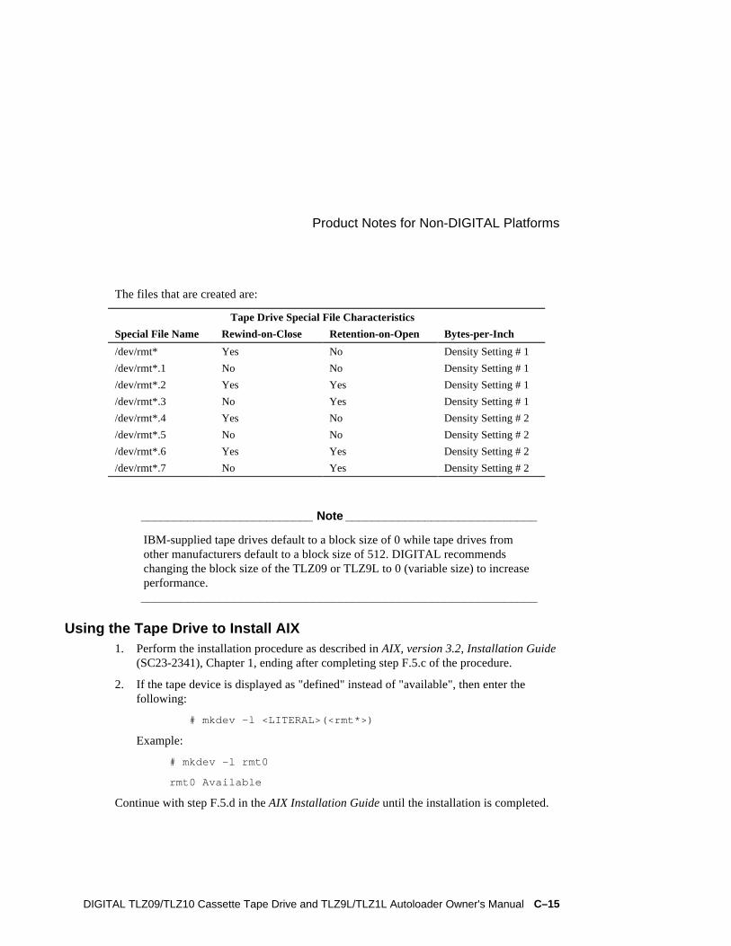
Product Notes for Non-DIGITAL Platforms
DIGITAL TLZ09/TLZ10 Cassette Tape Drive and TLZ9L/TLZ1L Autoloader Owner's Manual C–15
The files that are created are:
Tape Drive Special File Characteristics
Special File Name Rewind-on-Close Retention-on-Open Bytes-per-Inch
/dev/rmt* Yes No Density Setting # 1
/dev/rmt*.1 No No Density Setting # 1
/dev/rmt*.2 Yes Yes Density Setting # 1
/dev/rmt*.3 No Yes Density Setting # 1
/dev/rmt*.4 Yes No Density Setting # 2
/dev/rmt*.5 No No Density Setting # 2
/dev/rmt*.6 Yes Yes Density Setting # 2
/dev/rmt*.7 No Yes Density Setting # 2
__________________________ Note _____________________________
IBM-supplied tape drives default to a block size of 0 while tape drives fromother manufacturers default to a block size of 512. DIGITAL recommendschanging the block size of the TLZ09 or TLZ9L to 0 (variable size) to increaseperformance.____________________________________________________________
Using the Tape Drive to Install AIX1. Perform the installation procedure as described in AIX, version 3.2, Installation Guide
(SC23-2341), Chapter 1, ending after completing step F.5.c of the procedure.
2. If the tape device is displayed as "defined" instead of "available", then enter thefollowing:
# mkdev -l <LITERAL>(<rmt*>)
Example:
# mkdev -l rmt0
rmt0 Available
Continue with step F.5.d in the AIX Installation Guide until the installation is completed.

Product Notes for Non-DIGITAL Platforms
C–16 DIGITAL TLZ09/TLZ10 Cassette Tape Drive and TLZ9L/TLZ1L Autoloader Owner's Manual
Product Notes for Hewlett-PackardThis section describes how to include the TLZ09 or TLZ10 tape drive or TLZ9Lautoloader in an HP 9000 Series 700 system running HP-UX 9.05, 10.01, or 10.10 andSeries 800 system running HP-UX 10.10 and 10.20. The information covers configurationof the host system to communicate with the tape drive.
General InformationTape Drivers:
If the necessary drivers are not already built into your existing kernel, you will need torebuild your kernel. To determine which drivers are currently installed, issue the lsdevcommand.
The following drivers are used by the accompanying operating system:
OS Version Driver
9.05 scsitape
10.10, 10.20 stape
__________________________ Note ____________________________
The S800 tape2 driver is not supported. The stape driver is generally onlyavailable on newer model S800 computers. The TLZ10 and TLZ09 is notcompatible with fbackup.___________________________________________________________
When using the dump utility, you must supply the correct density code and tape lengthsize for dump to use in its calculations. Refer to the Section “Dump Parameters for theTape Drive” for details.
Compression can be enabled/disabled at any time by selecting the appropriate device filename. See the Section “System Device Files” for device names.
Modifications RequiredOperating System Patches:
HPUX requires software patches that must be applied for proper operation of tape drives.Patches can only be obtained directly from Hewlett-Packard. However, you can find a listof recommended patches on DIGITAL's StorageWorks web site:http://www.storage.digital.com.

Product Notes for Non-DIGITAL Platforms
DIGITAL TLZ09/TLZ10 Cassette Tape Drive and TLZ9L/TLZ1L Autoloader Owner's Manual C–17
Installation Procedure
__________________________ Note _____________________________
The “DEC TLZ09” or "DEC TLZ9" designation returned in response to SCSIinquiry during performance of the following procedure is the internal name forthe tape drive, as incorporated in and used by the firmware.____________________________________________________________
Installation of Tape DriveInstall the tape drive into the StorageWorks enclosure and power-on the workstation.Ensure that the address of the tape drive does not conflict with the address of any otherdevice on that SCSI bus.
Issue the ioscan -f command to determine if the kernel attached to the tape driver to thedevice on boot. If UNKNOWN or UNCLAIMED is displayed in the class column, proceedto the Section “System Modification.” If the driver is attached, skip that section.
System ModificationEnter the System Administration Manager (SAM) as superuser. From the first-level menu,choose Peripheral Devices. From the second-level menu, choose Tape Drives. Thesystem's hardware will be scanned, and the "available tape drives" window will identifythe tape drive as a SCSI tape drive (HP-UX 9.05), or as a DEC TLZ9 or DEC TLZ09 (HP-UX 10.x) with the appropriate hardware path. Highlight that selection and then pull downthe Actions menu and select the Add function. The program at this time will check thekernel to determine if the necessary drivers are built in, displaying the results.
If necessary, the program will rebuild the kernel. If this occurs, you will have to reboot thesystem in order to use the tape drive.
For further information on adding tape devices, refer to Hewlett-Packard's InstallingPeripherals manual (P/N B2355-40041) and to Configuring HPUX for Peripherals manual(P/N B2355-90053).
System Device FilesThe System Administration Manager program automatically creates the appropriatespecial device files and places them in the /dev/rmt directory when adding the devicethrough SAM. Additionally, if the appropriate drivers are built into the kernel, the devicefiles will be created automatically upon system initialization.

Product Notes for Non-DIGITAL Platforms
C–18 DIGITAL TLZ09/TLZ10 Cassette Tape Drive and TLZ9L/TLZ1L Autoloader Owner's Manual
HP-UX 9.05The following naming convention is used for the DDS-format tape drive, as shown in theexamples listed below:
/dev/rmt/c#d#[hlmc][n][b]
Where:
c# specifies the controller designation, which may contain either two or three characters, specifies the following:
where # is sc[f], in accordance with the following:
s is the system bus module:
2 = core I/O (the default) 4 = EISA SCSI
c is the slot number:
0 for core I/O n for EISA, the value is determined by the slot number as reported by the H/W path reported by "ioscan".
f is the function number. This value identifies the location on the core I/O bus. For the SCSI interface, the value is 1. If you are using the EISA SCSI interface, the value is 0.
d# designates the SCSI address of the tape drive, where # here identifies a number value.
h/l/m/c specifies density, with h meaning high density, l meaning low density, m meaning standard DDS format, and c meaning data compression2
n specifies no rewind on close.
b specifies Berkeley behavior.
For additional information about DDS tapes, refer to mt(7) of the HP-UX Referencemanual (P/N B 2355-90033) or the man pages.
2 The h, l, and m device designations all yield the same results. The c device designation enablescompression.

Product Notes for Non-DIGITAL Platforms
DIGITAL TLZ09/TLZ10 Cassette Tape Drive and TLZ9L/TLZ1L Autoloader Owner's Manual C–19
Examples:
For a tape drive installed in slot location 4 of the Digital StorageWorks
SWXSE-02 expansion enclosure connected to the main (core) SCSI bus, the
following device files would be produced in the directory /dev/rmt:
c201d4c c201d4l c201d4cb c201d4lb
c201d4cn c201d4ln c201d4cnb c201d4lnb
c201d4h c201d4m c201d4hb c201d4mb
c201d4hn c201d4mn c201d4hnb c201d4mnb
For a tape drive installed in slot location 4 of the digital StorageWorks SWXSE-02expansion enclosure connected to a SCSI adapter in EISA slot 1, the following device fileswould be produced in the directory /dev/rmt:
c410d4c c410d4l c410d4cb c410d4lb
c410d4cn c410d4ln c410d4cnb c410d4lnb
c410d4h c410d4m c410d4hb c410d4mb
c410d4hn c410d4mn c410d4hnb c410d4mnb
HP-UX 10.xThe following naming convention is used on systems which support long filenames for theDAT format tape drive as shown in the examples below:
/dev/rmt/c#t#d#BEST[n][b]
Where:
c# specifies the instance number of the interface card
t# specifies the SCSI address of the tape drive
d# specifies the device unit number (LUN) at the SCSI address
BEST specifies the highest capacity density, which for this device is the compressed format (8 GB)
NOMOD specifies default density.
n specifies no rewind on close
b specifies Berkeley behavior

Product Notes for Non-DIGITAL Platforms
C–20 DIGITAL TLZ09/TLZ10 Cassette Tape Drive and TLZ9L/TLZ1L Autoloader Owner's Manual
__________________________ Note ____________________________
The NOMOD file name must be used for the TLZ10. To create this file, use thefollowing procedure:-using SAM, select Peripheral Devices -select Tape Devices-select the (DEC ) TLZ10-go to Actions-select Create Device Files-select Create Custom Device File.
In the Custom Device File form change the Density field from BEST toNOMOD and then hit O.K. This will create a device file with NOMOD on theend.
Example, /dev/rmt/c#t#d#NOMOD.___________________________________________________________
Examples:
For the tape drive, set to SCSI address 4 connected to the main (core) SCSI bus, thefollowing device files would be produced in the directory /dev/rmt :
c0t4d0BEST c0t4d0BESTnb
c0t4d0BESTb c0t4d0BESTnb
For systems which do not support long filenames, the following device naming conventionis used:
#m #mb #mn #mnb
Where:
# specifies an arbitrary number to distinguish this tape drive from others.
n specifies no rewind on close
b specifies Berkeley behavior
To list the device files associated with each device, issue the command:
ioscan -f -n|more

Product Notes for Non-DIGITAL Platforms
DIGITAL TLZ09/TLZ10 Cassette Tape Drive and TLZ9L/TLZ1L Autoloader Owner's Manual C–21
Testing the Tape DriveTo test the tape drive, back up the "passwd" file to tape using the "tar" command asfollows (assuming that you installed the drive in accordance with the first precedingexample):
tar cvf /dev/rmt/c201d4h /etc/passwd
The system responds with something similar to the following:
a /etc/passwd 1 blocks
Note that depending on the size of the file, a different number of blocks may be reported.
VerificationUse the following command to verify that the "passwd" file was written to tape:
tar tvf /dev/rmt/c201d4h
The system responds with something similar to the following:
rw-r--r-- 0/10 535 Mar 23 16:31 1994 /etc/passwd
The installation and verification procedure is now complete.

Product Notes for Non-DIGITAL Platforms
C–22 DIGITAL TLZ09/TLZ10 Cassette Tape Drive and TLZ9L/TLZ1L Autoloader Owner's Manual
Dump Parameters for the Tape DriveThe parameters that should be used when running the dump utility with the tape drive are:
density = 61000 (for DDS1, DDS2, or DDS3 tapes)
size = one of the following, as appropriate:
6656 (for 60 meter tapes)
10240 (for 90 meter tapes)
20480 (for 120 meter tapes)
61440 (for 125 meter tapes)
blocking factor = 128
Example:
The following example shows the command for backing up an entire disk partition ontothe tape drive using a 120-meter tape (use the correct filename for the operating system inuse):
dump 0dsbf 61000 20480 128 /dev/rmt/c201d4h /usr
For further help, refer to man pages of the dump command.

DIGITAL TLZ09/TLZ10 Cassette Tape Drive and TLZ9L/TLZ1L Autoloader Owner's Manual Index–1
Index
BBusy LED, 5–2
CCartridge number indicators, 7–12Cassette magazine
setting the write-protect tab, 7–10Cassette tape
handling of, 5–5setting the write-protect tab, 5–6
Checking your shipment for tabletop autoloaders,1–8
Checking your shipment for tabletop drives, 1–8Cleaning requirements, 7–30
DDesign features, 1–2Diagnostics
console-based or self-tests, 6–4Digital audio tape (DAT), 1–2Digital data storage (DDS), 1–2DIGITAL service, 6–4
EEject button
TLZ1L, 7–13Enabling/Disabling Data Compression, B–1Enter button
TLZ1L, 7–12
Error indicator, 7–11
HHead cleaning, 6–1Head cleaning cassette, 6–2
IInserting a cassette tape into the drive, 5–7Installing
DS-TLZ10-DB tabletop drive, 2–1DS-TLZ1L-DB tabletop autoloader, 2–1TLZ09-AA/AB cassette tape drive, 3–1TLZ09-BA/BB cassette tape drive, 3–1TLZ09-DA/DB tabletop drive, 2–1TLZ10-AB cassette tape drive, 3–1TLZ10-BB cassette tape drive, 3–1TLZ9L-DB tabletop autoloader, 2–1
LLCD panel
TLZ1L, 7–13TLZ9L, 7–8
LCD panel alphanumeric display areaTLZ1L, 7–15
LCD panel icon areaTLZ1L, 7–14
LED indicators, 7–2
MMedia Recognition System (MRS), 1–3

Index
Index–2 DIGITAL TLZ09/TLZ10 Cassette Tape Drive and TLZ9L/TLZ1L Autoloader Owner's Manual
OOrdering additional cassettes, 1–9
PPower cable, 2–4, 3–6Power switch, 5–1Power-on self-test, 4–1Preventive maintenance, 6–1Problem solving, 6–3Product description, 1–1
SSCSI signal cable
device to device, 2–4device to system, 2–3drive to system, 3–6
Select buttonTLZ1L, 7–12
Status LED, 5–2System support, 1–2
TTape LED, 5–2TLZ09 cassette tape drive
busy LED, 5–2indicators, 5–6installation verification, 4–1location of buttons, switches, connectors, 2–2power switch, 5–1specifications, A–1status LED, 5–2tape LED, 5–2unload button, 5–1using, 5–1
TLZ09 models, 1–3TLZ10 cassette tape drive
busy LED, 5–2indicators, 5–6installation verification, 4–1location of buttons, switches, connectors, 2–2power switch, 5–1specifications, A–1status LED, 5–2tape LED, 5–2
unload button, 5–1using, 5–1
TLZ10 models, 1–3TLZ1L cassette tape autoloader
autoload function, 7–29automatic operations, 7–21eight cartridge mode, 7–23Eject button, 7–13ejecting magazine, 7–27Enter button, 7–12LCD panel, 7–13LCD panel alphanumeric display area, 7–15LCD panel icon area, 7–14LED indicators, 7–2loading cartridges into magazine, 7–25loading magazine, 7–26location of buttons, switches, connectors, 2–2magazine operations, 7–23manual operations, 7–22operation, 7–21SCSI ID select switch, 7–30Select button, 7–12seven cartridge mode, 7–24single cartridge mode, 7–24specifications, A–4unloading cartridges from magazine, 7–28using, 7–1
TLZ1L models, 1–4TLZ9L cassette tape autoloader
7-segment display, 7–11autoload function, 7–29automatic operations, 7–21cartridge number indicators, 7–12eight cartridge mode, 7–23ejecting magazine, 7–27error indicator, 7–11LCD panel, 7–8LED indicators, 7–2loading cartridges into magazine, 7–25loading magazine, 7–26location of buttons, switches, connectors, 2–2magazine operations, 7–23manual operations, 7–22operation, 7–21SCSI ID select switch, 7–30seven cartridge mode, 7–24

Index
DIGITAL TLZ09/TLZ10 Cassette Tape Drive and TLZ9L/TLZ1L Autoloader Owner's Manual Index–3
single cartridge mode, 7–24specifications, A–4switch settings, 7–29switchpack settings, 7–29unloading cartridges from magazine, 7–28using, 7–1warning indicator, 7–9write-protect indicator, 7–10
TLZ9L models, 1–4
UUnload button, 5–1
WWarning indicator, 7–9Write-protect indicator, 7–10Write-protect tab, 5–6, 7–10

SES Template Word 7 Blank Page Fix by Peter LaQuerre