digital weighing indicator xk3190-a12+ss - yaohua.cc key, indicator will deduct the displayed weight...
TRANSCRIPT

Digital Weighing Indicator XK3190-A12+SS
User Manual
V 1.10
Shanghai Yaohua Weighing System Co., Ltd

XK3190-A12+SS V1.10
1
Content CHAPTER 1 MAIN SPECIFICATIONS…………………………….…………………….. 2 CHAPTER 2 APPEARANCE AND INSTALLATION…………………….…………….. 3 2.1 KEY FUNCTIONS…………………………………………………………………..….. 3
2.2 LOAD CELL CONNECTION…………………………………………………………... 3
2.3 SCOREBOARD CONNECTION TO THE INDICATOR…………………………..…4
2.4 SERIAL COMMUNICATION AND INDICATOR CONNECTION ……………….….4
CHAPTER 3 CALIBRATION…………………………………………………………….... 5 3.1 GENERAL CALIBRATION……………………………………………………………...5
3.2 FAST CALIBRATION…………………………………………………………………... 6
CHAPTER 4 OPERATION………………………………………………………………….7 4.1 POWER ON AND AUTO ZERO-SETTING………………………………………..… 7
4.2 MANUAL ZERO SETTING………………………………………………………..…… 7
4.3 TARE FUNCTION ……………………………………………………………………… 7
4.4 ACCUMULATING FUNCTION …………………………………………………….….. 7
4.5 COUNTING FUNCTION………………………………………………………………... 7
4.6 USER’S FUNCTION SETTING………………………………………………………... 7
CHAPTER 5 MAINTENANCE................................................................................... 9 CHAPTER 6 ERROR INDICATION……………………………………………………….10 DEAR CUSTOMERS, PLEASE READ THE USER GUIDE CAREFULLY BEFORE USING THE INDICATOR!

XK3190-A12+SS V1.10
2
Chapter 1 Main Specifications
1. Model: XK3190-A12+SS weighing indicator
2. Accuracy: Grade Ⅲ, n=3000
3. Sample Rate: 10 times / second
4. Load cell sensitivity: 1.5~3mV / V
5. Scale interval: 1/2/5/10/20/50 for option
6. Display: 6 bits LCD,6 state indicating signals
7. Scoreboard interface (optional): In serial output mode:current loop signal,
transmission distance≤2000m
8. Communication interface (optional): RS232C;Baud rate 1200/2400/4800/9600
optional
9. Power supply: Battery DC 6V/2.8AH
10. Operating temperature: 0~40℃
11. transporting temperature: -25~55℃
12. relative humidity: ≤85%RH
Features: 1. High precision A/D conversion,readability 1/30000;
2. call and display inner code to replace weight observing and analysis tolerance
3. special digital filtering technology to strengthen anti-vibration ability
4. able to set up digital filter intensity, range and stable time
5. with counting function (unit weight data save protection in case of power off)
6. selectable backlight mode
7. Optional RS232 interface, baud rate selectable, communication method selectable.
8. Optional 20mA current loop as interface for scoreboard
9. Non standard function ( customized modification)
(1) KG/LB switch function
(2) Live stock (animal ) weighing
(3) TTL two fixed value output;
(4) Peak value

XK3190-A12+SS V1.10
3
CHAPTER 2 APPEARANCE AND INSTALLATION 2.1 KEY FUNCTIONS Key Function
【 # 】 When turning on the indicator, keep pressing this key to enter the
calibration mode
【Func 】 In weighing mode, keep pressing this key for more than 5 seconds
to enter the user parameters setting mode, less than 5 seconds will
enter into counting mode. 【 * 】 In counting mode, press this key for sample taking
【 Tare 】 In weighing mode, press this key to tare
【 Zero 】 In weighing mode, press this key to zero
【ON/OFF】 Power on/off 2.2 LOAD CELL CONNECTION 1. load cell adopts the 5-pin interface. Definition of each feet refers to picture 2-3.
2. Indicator adopts 4-wire connection as default. ▲. Indicator must be reliably connected to load cell, and the shielded-cable of load cell
must be reliably connected to underground.
▲. To protect the indicator and load cell, we cannot plug or withdraw the connector when
the indicator is power on.
▲. Both the load cell and indicator are static sensitive devices. You must adopt anti-static
measures. The electric welding operation and other strong electric operation on the scale
platform are strictly prohibited. In order to protect the operator, indicator, and relevant
devices, you should install lightning rod in the thunderstorm frequently happen area.
Indicator 5-pin interface (picture 2-3 load cell connection)

XK3190-A12+SS V1.10
4
(picture 2-4 indicator connection with computer and scoreboard)
2.3 SCOREBOARD CONNECTION TO THE INDICATOR (OPTIONAL ) Scoreboard signal is 20mA current loop, output in ASC II, output baud rate 600.
connection method refer to picture 2-4.
2.4 SERIAL COMMUNICATION AND INDICATOR CONNECTION (OPTIONAL)
XK3190-A12+SS can use optional RS232 serial communication interface to communicate with computer. The connection method, please refer to picture 2-4. With RS232(optional) serial communication interface.All data are ASCII code, every set of which is composed of 10 bits: the 1st is starting bit, the 10th is stop bit, the middle in between are 8 data bits. Communication mode as follows: (1) In continuous mode: The data transmitted is weight (Gross weight, net weight or tare) The format of G.W.:ww000.000kg or ww000.000lb
Make sure that scoreboard and output lead wires are connected correctly. If there is something wrong with connection, damage will happen to output port of instrument and input port of scoreboard, sometimes, the damage is so big to influence the instrument and scoreboard. Only specially provided connecting cable is allowed to be used.
Make sure that communication interface output lead and computer are correctly connected, if there is something wrong with connection, damage will happen to output port of instrument and input port of computer, sometimes, the damage is so big that instrument, computer and corresponding peripherals are got involved.
Necessary computer technology and programming expertise are required for computer
communication, which should be participated and instructed by professionals.
Non-professional staff is supposed not to be involved in this regard.

XK3190-A12+SS V1.10
5
The format of N.W: wn000.000kg or wn000.000lb The format of Tare: wt000.000kg or wt000.000lb Note:The position of above decimal is decided by the decimal set on the indicator. (2) In command mode (all of them are ASCII):
The indicator performs the corresponding operation according to the command transmitted from the indicator. Command R The indicator receives and sends weight data once time (the format
is the same as the continuous mode) Command T The indicator receive the command and tare (the same as tare key); if
no receipt of the command. The indicator returns CR LF
Command Z The indicator receives the command and zero (the same as zero key);
if no receipt of the command, the indicator returns CR LF.
Chapter 3 Calibration
3.1 GENERAL CALIBRATION Connect load cell properly, then turn on the indicator, keep pressing [#] key while it’s
initializing, it will enter the calibration mode, and display 【d X 】.
STEP OPERATION DISPLAY NOTES
1
Press [TARE] to change
the division, and press [#] to confirm
[d X ]
Division setting. For example: Press [#] when displayed【d 5】,
then the division is set to be“5”, and the indicator
enters decimal point setting.
Note: The 10, 20, 50 divisions are only valid when
there is no decimal point. When there is a decimal
point, the 10, 20, 50 divisions will be turned to 1, 2,
and 5 automatically.
2
Press [TARE] to change
the decimal point, and press[#] to confirm [P X ]
Decimal point setting For example: Press [#] when displayed【P 0.000】, then the decimal point is set to be “0.000”, and the indicator enters full capacity setting Note: When there is a decimal point, division 10, 20, 50 are invalid, and will be turned to 1, 2, and 5 automatically.

XK3190-A12+SS V1.10
6
3
Press [TARE] to select the digit bit; Press [ZERO] to change the value;
Press [#] for confirm the
input of full capacity
[FULL ]
Full capacity setting For example: Press [#] when displayed【025000】, then the full capacity is set to be “25000”, and the indicator enters zero point calibration
4
Make sure there is no load on scale, and press [#] when the stable indication
sign is on
[nOLOAD]
Zero point calibration
5
Add full capacity load, press [TARE] to continue [AdLOAD]
Calibrate the full capacity For example: Load 25000 weight on scale(as we set in step 3) Use [TARE] and [ZERO] to change the value to be 25000. When stable indication sign is on, press [#] to confirm.
Press [TARE] to select the digit bit; Press [ZERO] to change the value accordingly with the full capacity; Press [#] to confirm when the stable indication sign is on
[025000]
6
Press the calibration switch
at the back housing of the
indicator. [ End]
It saves the calibration parameter and back to the weighing mode. Note: if no pressing the calibration switch at back of indicator, all the parameters won’t be saved.
3.2 FAST CALIBRATION Connect load cell properly, then turn on the indicator, keep pressing [ # ] key while its
initialization, it will enter into the calibration mode, and display 【d X 】.
3.2.1 Fast calibration of zero point At any time before it showing [nOLOAD], press [FUNC]. Indicator will keep the original
division, decimal point, full capacity, and enter the zero point calibration directly. Making
sure there is no load on the scale, and the stable indication sign is on, press [ZERO] to
re-calibrate the zero point. The indicator will display [End]. Press the calibration switch at
the back of the indicator to save the setting and get back to the weighing status.
3.2.2 Fast calibration of full capacity At any time before it showing [AdLOAD], press [*]. It keeps the original division, decimal
point, full capacity, zero point, and enters into the full capacity calibration directly. After the
full capacity is reset, press the calibration switch at the back of the indicator to save the
setting and get back to the weighing status.

XK3190-A12+SS V1.10
7
Chapter 4 Operation
4.1 POWER ON AND AUTO ZERO-SETTING 4.1.1 The indicator will perform “000000-999999” to self-checking when turning on. Then it
will enter weighing mode. 4.1.2 When power on, if loading weight on the scale deviates from the zero point, but still
within zero set range, the indicator will set zero automatically; if out of range, it is necessary to adjust the zero point or recalibrate or reset.
4.2 MANUAL ZERO SETTING (AUTOMATICALLY) 4.2.1 In weighing mode, when there is some error when unloaded, press [Zero] to make
the indicator to be zero.
4.2.2 If the displayed value deviates from zero point, but still within zero-range, pressing
[Zero] key is available. Otherwise, [Zero] key is invalid. (In this status, please
recalibrate or reset zero parameters)
4.2.3 Only when stable annunciator is on, zero operation can be available. 4.3 TARE FUNCTION When Indicator at weighing status, and displaying positive weight stable, press [ Tare ]
key, indicator will deduct the displayed weight value as tare weight. Then indicator
displays net weight as “0 ”, and Tare sign annunciator is on.
4.4 COUNTING FUNCTION In weighing mode, press [Func] to enter the counting state, it will display “count”, and press [*], it will display “C00000”, then press [Tare] to move the digit corresponding with the small triangle, press [ZERO] key the digit where the triangle is will increase one, input sample number, press [*] to enter into counting mode, the corresponding indicating triangle light will be on. Press [Func] to return back to weighing mode. In counting mode, the display will show “count”, press [*] twice, it will enter into counting mode directly, indicator will calculating the sample and display it. (in this process, if “ERR 4” shows, it means the sample is failed, indicator will show last time’s sample.) 4.5 ACCUMULATING FUNCTION In weighing mode, press [ * ] key, indicator will accumulate current weight, press [*] again,
it will return back to weighing mode.
In zero mode, press [*], it will show current accumulating value, in the accumulating mode,
press [Func] to zero the weight. 4.6 USER’S FUNCTION SETTING
XK3190-A12+SS V1.10
8
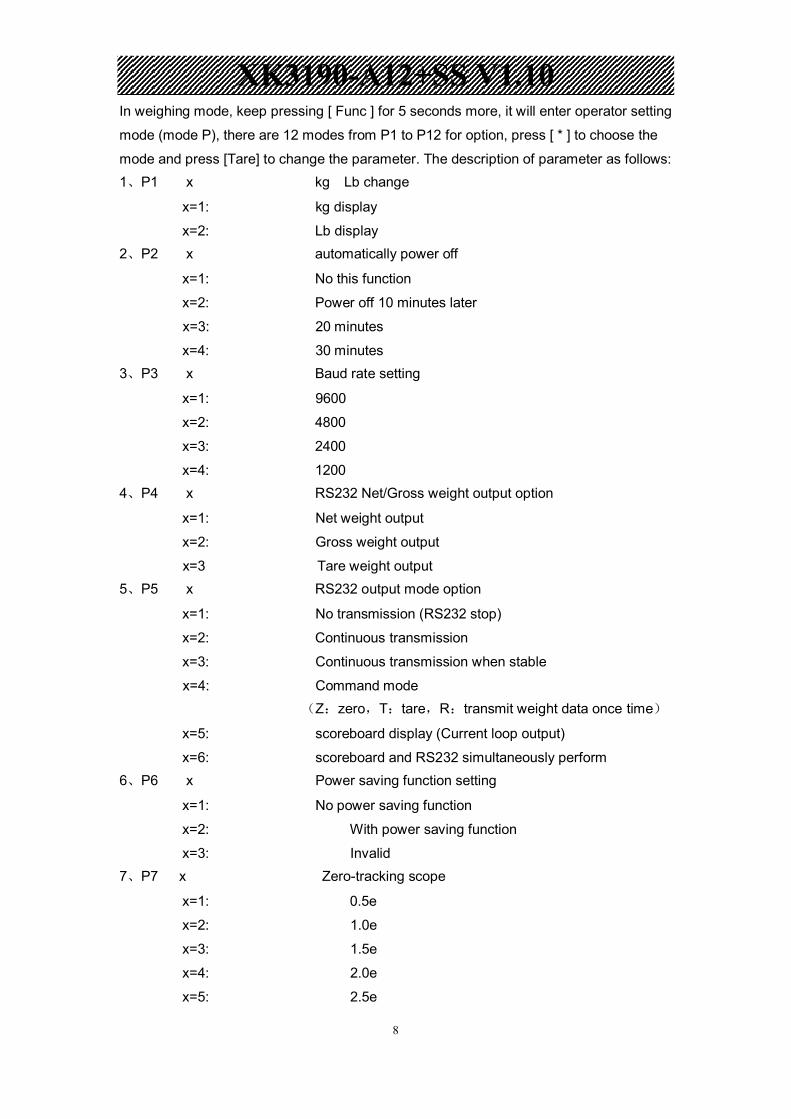
In weighing mode, keep pressing [ Func ] for 5 seconds more, it will enter operator setting
mode (mode P), there are 12 modes from P1 to P12 for option, press [ * ] to choose the
mode and press [Tare] to change the parameter. The description of parameter as follows: 1、P1 x kg Lb change
x=1: kg display
x=2: Lb display 2、P2 x automatically power off
x=1: No this function
x=2: Power off 10 minutes later
x=3: 20 minutes
x=4: 30 minutes 3、P3 x Baud rate setting
x=1: 9600
x=2: 4800
x=3: 2400
x=4: 1200 4、P4 x RS232 Net/Gross weight output option
x=1: Net weight output
x=2: Gross weight output
x=3 Tare weight output 5、P5 x RS232 output mode option
x=1: No transmission (RS232 stop)
x=2: Continuous transmission
x=3: Continuous transmission when stable
x=4: Command mode (Z:zero,T:tare,R:transmit weight data once time)
x=5: scoreboard display (Current loop output)
x=6: scoreboard and RS232 simultaneously perform 6、P6 x Power saving function setting
x=1: No power saving function
x=2: With power saving function
x=3: Invalid 7、P7 x Zero-tracking scope
x=1: 0.5e
x=2: 1.0e
x=3: 1.5e
x=4: 2.0e
x=5: 2.5e

XK3190-A12+SS V1.10
9
x=6: 3.0e
x=7: 5.0e
x=8: Tracking forbidden 8、P8 x Zero key scope
x=1: 2%FS
x=2: 4%FS
x=3: 10%FS
x=4: 20%FS
x=5: 100%FS 9、P9 x Zero scope upon starting
x=1: 2%FS
x=2: 4%FS
x=3: 10%FS
x=4: 20%FS
x=5: 100%FS
x=6: Start ZERO forbidden 10、P10 x Digital filtering intensity
x=1: high
x=2: middle
x=3: low
11. P11 x Stable time
x=1: high
x=2: middle
x=3 low
12. P12 x Stable extent
x=1: low
x=2: middle
x=3: high
Chapter 5 Maintenance 5.1 To ensure the clarity and service life of the indicator, it must be kept away from direct
sunlight during using, and the ground where the indicator stands must be smooth.
5.2 It is improper to use this indicator in a dustful or vibrant or damp environment.
5.3 The load cell and indicator need good connection. System must have a good ground
connection, and kept away from strong electric field, strong magnetic field. The load cell
and indicator must be kept away from strong corrosive substances and inflammable&
XK3190-A12+SS V1.10
10
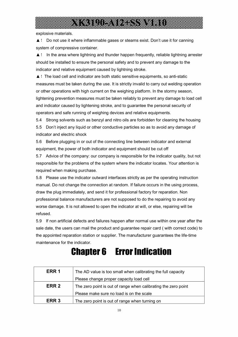
explosive materials. ▲! Do not use it where inflammable gases or steams exist. Don’t use it for canning
system of compressive container. ▲! In the area where lightning and thunder happen frequently, reliable lightning arrester
should be installed to ensure the personal safety and to prevent any damage to the
indicator and relative equipment caused by lightning stroke. ▲!The load cell and indicator are both static sensitive equipments, so anti-static
measures must be taken during the use. It is strictly invalid to carry out welding operation
or other operations with high current on the weighing platform. In the stormy season,
lightening prevention measures must be taken reliably to prevent any damage to load cell
and indicator caused by lightening stroke, and to guarantee the personal security of
operators and safe running of weighing devices and relative equipments.
5.4 Strong solvents such as benzyl and nitro oils are forbidden for cleaning the housing
5.5 Don’t inject any liquid or other conductive particles so as to avoid any damage of
indicator and electric shock
5.6 Before plugging in or out of the connecting line between indicator and external
equipment, the power of both indicator and equipment should be cut off
5.7 Advice of the company: our company is responsible for the indicator quality, but not
responsible for the problems of the system where the indicator locates. Your attention is
required when making purchase.
5.8 Please use the indicator outward interfaces strictly as per the operating instruction
manual. Do not change the connection at random. If failure occurs in the using process,
draw the plug immediately, and send it for professional factory for reparation. Non
professional balance manufacturers are not supposed to do the repairing to avoid any
worse damage. It is not allowed to open the indicator at will, or else, repairing will be
refused.
5.9 If non artificial defects and failures happen after normal use within one year after the
sale date, the users can mail the product and guarantee repair card ( with correct code) to
the appointed reparation station or supplier. The manufacturer guarantees the life-time
maintenance for the indicator.
Chapter 6 Error Indication
ERR 1 The AD value is too small when calibrating the full capacity
Please change proper capacity load cell
ERR 2 The zero point is out of range when calibrating the zero point
Please make sure no load is on the scale
ERR 3 The zero point is out of range when turning on

XK3190-A12+SS V1.10
11
Warning: when this indicator is installed to electronic weighing instrument, a tag conform
with national regulation must be stick on products.
Office address :NO. 4238 Shendu Road, Minhang District, Shanghai
Zip Code: 201112
Tel:(021)67282800 67282801 67282802
Fax:(021)58860003
Web: www.yaohua.com.cn
Sales line:
Tel:(021)67282822, 67282819
Fax:(021)67282826
After sales:
Tel:800 820 5030 (021)67282812
Fax:(021)67282810
Email:[email protected] [email protected]
Please make sure no load is on the scale when turning on
ERR 4 The input sample quantity is zero when sampling in counting mode
Please input the right sample quantity
ERR 5 When full capacity calibrating, the weight input is zero
Please input the weight in accordance with the load on scale
ERR 6 The unit weight is less than 0.25e when sampling in counting mode
Please re-input the sample quantity
ERR 7 Load cell connection wire with problem, add load in calibration leads AD
negative increase.
bAt-lo Low battery