dimension handbook
TRANSCRIPT

Dimension HandbookNS-type
Size 20”(500mm) ~ 40”(1000mm)

CONTENTS
Pipes
Table 1
Table 1
Fittings
Table 2
Table 2
Table 3
Table 4
Table 5
Table 6
Table 7
Table 8
Table 9
Table 10
Table 11
Table 12
Table 13
Table 14
Table 15
Table 16
Table 17
Table 18
Table 19
Table 20
Table 21
Accessories
Table 22
Table 22
Table 23
Table 23
NS-Pipes (Size 20”~ 40”) ……………………………………………………………………… 1
NS-Pipes (Size 20”~ 40”) ……………………………………………………………………… 2
NS-Fittings (Size 12”~ 16”) for Tees and Reducers ……………………………………… 3
NS-Fittings (Size 20”~ 40”) …………………………………………………………………… 4
NS-Triple Socket Crosses (Size 20”~ 36”)…………………………………………………… 5
NS-Duble Socket Tees (Size 20”~ 40”) ……………………………………………………… 6
NS-Socket Spigot Reducers (Size 20”~ 40”) ………………………………………………… 7
NS-Spigot Socket Reducers (Size 20”~ 40”) ………………………………………………… 8
NS-Socket Spigot Bends 90° (Size 20”~ 40”)………………………………………………… 9
NS-Socket Spigot Bends 45° (Size 20”~ 40”)………………………………………………… 10
NS-Socket Spigot Bends 22 1/2° (Size 20”~ 40”)…………………………………………… 11
NS-Socket Spigot Bends 11 1/4° (Size 20”~ 40”)…………………………………………… 12
NS-Socket Spigot Bends 5 5/8° (Size 20”~ 40”) …………………………………………… 13
NS-Double Socket Bends 45° (Size 20”~ 40”) ……………………………………………… 14
NS-Double Socket Bends 22 1/2° (Size 20”~ 40”) ………………………………………… 15
NS-Socket Flanged Tees with Flanged Branch (Size 20”~ 40”)
(For use in Gate Valve Chamber) …………………………………………………………… 16
NS-Flanged Spigot Tees with Flanged Branch (Size 20”~ 40”)
(For use in Gate Valve Chamber) …………………………………………………………… 17
NS-Socket Spigot Tees with Flanged Branch (Size 20”~ 40”)
(For Air Valves, Fire Hydrants and Manholes) …………………………………………… 18
NS-Double Socket Level Invert Tees with Socket Branch (Size 20”~ 40”) …………… 19
NS-Collars (Size 20”~ 40”) …………………………………………………………………… 20
NS-Flanged Socket (Size 20”~ 40”) ………………………………………………………… 21
NS-Flanged Spigot (Size 20”~ 40”)…………………………………………………………… 22
NS-Plugs (Size 20”~ 40”) ……………………………………………………………………… 23
NS-Jointing Accessories (1) Gland for Fittings (Size 12”~ 16”) ………………………… 25
NS-Jointing Accessories (1) Gland for Pipes and Fittings (Size 20”~ 40”) …………… 26
NS-Jointing Accessories (2) Lock Ring (Size 12”~ 16”) …………………………………… 27
NS-Jointing Accessories (2) Lock Ring (Size 20”~ 40”) …………………………………… 28
Table 24
Table 24
Table 25
Table 25
Table 26
Table 27
Table 27
Table 28
Table 29
Table 29
NS-Jointing Accessories (3) Liner (Size 12”~ 16”) ………………………………………… 29
NS-Jointing Accessories (3) Liner (Size 20”~ 40”) ………………………………………… 30
NS-Jointing Accessories (4) Spigot Ring for Cut Pipe Rivet Type (Size 12”~ 16”)…… 32
NS-Jointing Accessories (4) Spigot Ring for Cut Pipe Rivet Type (Size 20”~ 40”)…… 34
NS-Jointing Accessories (5) T-head Bolts and Nuts………………………………………… 36
NS-Jointing Accessories (6) Rubber Gaskets (Size 12”~ 16”) …………………………… 37
NS-Jointing Accessories (6) Rubber Gaskets (Size 20”~ 40”) …………………………… 38
NS-Jointing Accessories (7) Lock Ring Centering Rubbers (Size 12”~ 16”) …………… 39
NS-Jointing Accessories (8) Backup Rings (Size 12”~ 16”) ……………………………… 40
NS-Jointing Accessories (8) Backup Rings (Size 20”~ 40”) ……………………………… 41

Table 1 NS-
Outside Diameter(inches)
Size(inches)
Thickness(inches) Dimensions (inches)
Note : Pipe shape can be as the dashed line.
20
24
28
32
36
40
0.33
0.39
0.43
0.47
0.51
0.57
20.79
24.83
28.86
32.91
36.97
40.98
21.42
25.54
29.65
33.70
37.76
41.77
25.75
29.84
34.49
38.78
43.23
47.52
27.56
31.65
36.61
40.91
45.83
50.12
0.91
0.91
1.06
1.06
1.30
1.30
11.61
11.61
13.07
13.39
13.39
13.70
0.16
0.16
0.24
0.24
0.24
0.24
2.36
2.36
3.15
3.15
3.15
3.15
2.95
2.95
2.95
2.95
2.95
3.15
1
Pipes
Size 20”~ 40”
Detail of ASize 20”~ 28” Size 32”~ 40”
Size(inches)
No. of Bolt
Nominal laying
length (feet)
Socket Spigot Projection
Thickness(inches)Iron Mass
Per Piece
Per foot of Straight portion
Per Piece
Per foot of Straight portion
Lining (reference)Mass lb
lb
14
14
16
20
20
20
243
291
406
509
622
741
2.1
2.5
5.5
6.3
7.0
14.2
66.7
93.7
119.9
149.3
181.7
224.9
1541
2114
2734
3417
4167
5115
0.24
0.24
0.31
0.31
0.31
0.39
15.3
18.3
28.4
32.5
36.5
70.6
298
357
553
631
710
981
20
24
28
32
36
40
19.69
19.69
19.69
19.69
19.69
19.69
Spigot projections will be welded or casted by suitable method. In this case, pull-out resistance will be more than 17,000 Din lbf.( Din : Nominal Diameters inches)
Note :
2

Table 2 NS- Fittings
( For Tees and Reducers )
Section
Outside Diameter(inches)
Size(inches) Dimensions (inches)
No. of Bolt
Mass
Socket Spigot Projection
12
16
12.71
16.76
16.97
21.10
18.78
22.91
13.06
17.13
0.91
0.91
5.55
5.63
0.12
0.12
8
12
73.9
102
0.4
0.5
lb
Size12”~ 16”
Fitting shape can be as the dashed line.Note :
3
Table 2 NS- Fittings
Size 20”~ 40”
Detail of ASize 20”~ 28” Size 32”~ 40”
Outside Diameter(inches)
Size(inches) Dimensions (inches)
No. of Bolt
Mass
Socket Spigot Projection
lb
20
24
28
32
36
40
20.79
24.83
28.86
32.91
36.97
40.98
21.42
25.54
29.65
33.70
37.76
41.77
25.75
29.84
34.49
38.78
43.23
47.52
27.56
31.65
36.61
40.91
45.83
50.12
0.91
0.91
1.06
1.06
1.30
1.30
5.94
5.94
7.36
7.68
7.68
7.95
0.16
0.16
0.24
0.24
0.24
0.24
2.36
2.36
3.15
3.15
3.15
3.15
14
14
16
20
20
20
190
231
346
421
505
595
6.3
7.5
17.6
20.0
22.5
24.7
Fitting shape can be as the dashed line.Note :
4

Table 3 Triple Socket Crosses
Size 20”~ 36”
Size (inches) Thickness (inches) Dimensions (inches) Masslb
20
24
28
32
36
16
16
20
24
28
0.59
0.63
0.67
0.71
0.75
0.55
0.55
0.59
0.63
0.67
18.90
21.65
24.41
27.17
30.31
18.11
20.87
23.62
26.38
29.53
33.46
36.22
38.58
40.55
42.91
52.36
57.87
62.99
67.72
73.23
981
1237
1814
2293
3020
5
Table 4 Double Socket Tees
Size 20”~ 40”
Size(inches)
Thickness(inches) Dimensions (inches) Mass
lb
2020
242424
282828
32323232
36363636
404040
16 20
16 20 24
20 24 28
20 24 28 32
24 28 32 36
24 32 36
0.590.59
0.630.630.63
0.670.670.67
0.710.710.710.71
0.750.750.750.75
0.790.790.79
0.550.59
0.550.590.63
0.590.630.67
0.590.630.670.71
0.630.670.710.75
0.630.710.79
18.9018.90
21.6521.6521.65
24.4124.4124.41
27.1727.1727.1727.17
23.6230.3130.3130.31
26.7733.0733.07
18.1118.11
20.8720.8720.87
23.6223.6223.62
26.3826.3826.3826.38
27.1729.5329.5329.53
30.3132.2832.28
33.4633.46
36.2236.2236.22
38.5838.5838.58
40.5540.5540.5540.55
37.0142.9142.9142.91
38.9844.8844.88
52.3652.36
57.8757.8757.87
62.9962.9962.99
67.7267.7267.7267.72
60.6373.2373.2373.23
65.7577.9577.95
842946
109611971254
157216271761
1940199521272227
2136257926682778
260131533395
6
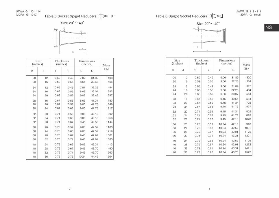
Table 5 Socket Spigot Reducers
Size 20”~ 40”
Size(inches)
Thickness(inches)
Dimensions(inches) Mass
lb
2020
242424
282828
323232
36363636
40404040
12 16
12 16 20
16 20 24
20 24 28
20 24 28 32
24 28 32 36
0.49 0.55
0.49 0.55 0.59
0.55 0.59 0.63
0.59 0.63 0.67
0.59 0.63 0.67 0.71
0.63 0.67 0.71 0.75
7.87 8.66
7.87 8.66 9.06
8.66 9.06 9.06
9.06 9.06 9.45
9.06 9.06 9.45 9.45
9.06 9.45 9.45 10.24
31.89 32.68
32.28 33.07 33.46
41.34 41.73 41.73
42.13 42.13 42.52
42.52 42.52 42.91 42.91
43.31 43.70 43.70 44.49
408456
494542597
783849917
99210561144
1160121913011380
1413149015631664
0.59 0.59
0.63 0.63 0.63
0.67 0.67 0.67
0.71 0.71 0.71
0.75 0.75 0.75 0.75
0.79 0.79 0.79 0.79
7
Table 6 Spigot Socket Reducers
Size 20”~ 40”
Size(inches)
Thickness(inches)
Dimensions(inches) Mass
lb
2020
242424
282828
323232
36363636
40404040
1216
121620
162024
202428
20242832
24283236
0.590.59
0.630.630.63
0.670.670.67
0.710.710.71
0.750.750.750.75
0.790.790.790.79
0.490.55
0.490.550.59
0.550.590.63
0.590.630.67
0.590.630.670.71
0.630.670.710.75
9.069.06
9.069.069.06
9.459.459.45
9.459.459.45
10.2410.2410.2410.24
10.2410.2410.2410.24
31.8932.28
31.8932.2833.07
40.5541.3441.73
41.3441.7342.13
42.1342.5242.9143.31
42.5242.9143.3143.70
320384
375434564
584725827
8028991078
910100111751321
1105127214111572
8
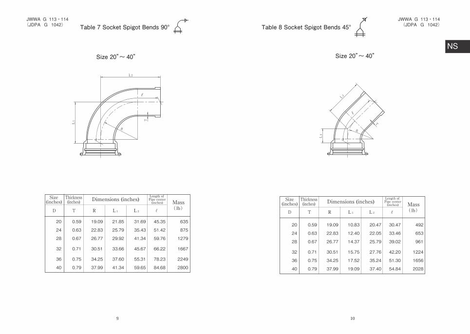
Table 7 Socket Spigot Bends 90°
Size(inches)
Thickness(inches) Dimensions (inches)
Length of Pipe center(inches) Mass
lb
20
24
28
32
36
40
0.59
0.63
0.67
0.71
0.75
0.79
19.09
22.83
26.77
30.51
34.25
37.99
21.85
25.79
29.92
33.66
37.60
41.34
31.69
35.43
41.34
45.67
55.31
59.65
45.35
51.42
59.76
66.22
78.23
84.68
635
875
1279
1667
2249
2800
Size 20”~ 40”
9
20
24
28
32
36
40
0.59
0.63
0.67
0.71
0.75
0.79
19.09
22.83
26.77
30.51
34.25
37.99
10.83
12.40
14.37
15.75
17.52
19.09
20.47
22.05
25.79
27.76
35.24
37.40
30.47
33.46
39.02
42.20
51.30
54.84
492
653
961
1224
1656
2028
Table 8 Socket Spigot Bends 45°
Size(inches)
Thickness(inches) Dimensions (inches)
Length of Pipe center(inches) Mass
lb
Size 20”~ 40”
10

Table 9 Socket Spigot Bends 22 1/2°
Masslb
20
24
28
32
36
40
0.59
0.63
0.67
0.71
0.75
0.79
19.09
22.83
26.77
30.51
34.25
37.99
6.69
7.48
8.46
9.25
10.04
10.83
24.21
24.61
29.53
32.28
38.39
40.94
30.83
31.97
37.87
41.38
48.27
51.57
494
635
944
1208
1587
1944
Size(inches)
Thickness(inches) Dimensions (inches)
Length of Pipe center(inches)
Size 20”~ 40”
11
Table 10 Socket Spigot Bends 11 1/4°
Masslb
20
24
28
32
36
40
0.59
0.63
0.67
0.71
0.75
0.79
19.09
22.83
26.77
30.51
34.25
37.99
6.69
7.48
8.46
9.25
10.04
10.83
24.21
24.41
29.33
32.28
38.19
40.75
30.91
31.89
37.80
41.54
48.19
51.54
496
633
941
1210
1587
1944
Size(inches)
Thickness(inches) Dimensions (inches)
Length of Pipe center(inches)
Size 20”~ 40”
12

Table 11 Socket Spigot Bends 5 5/8°
Masslb
20
24
28
32
36
40
0.59
0.63
0.67
0.71
0.75
0.79
19.09
22.83
26.77
30.51
34.25
37.99
6.69
7.48
8.46
9.25
10.04
10.83
24.21
24.41
29.33
32.28
38.19
40.75
30.91
31.89
37.80
41.54
48.19
51.57
496
633
941
1210
1587
1944
Size(inches)
Thickness(inches) Dimensions (inches)
Length of Pipe center(inches)
Size 20”~ 40”
13
Table 12 NS-Double Socket Bends 45°
Size 20”~ 40”
Masslb
20
24
28
32
36
40
0.59
0.63
0.67
0.71
0.75
0.79
19.09
22.83
26.77
30.51
34.25
37.99
10.83
12.4
14.37
15.75
17.52
19.09
20.83
23.82
27.6
30.2
33.58
36.54
582
758
1116
1402
1748
2130
Size(inches)
Thickness(inches) Dimensions (inches)
Length of Pipe center(inches)
14

Size 20”~ 40”
Masslb
20
24
28
32
36
40
0.59
0.63
0.67
0.71
0.75
0.79
19.09
22.83
26.77
30.51
34.25
37.99
6.69
7.48
8.46
9.25
10.04
10.83
13.31
14.84
16.81
18.35
19.92
21.46
509
646
950
1182
1446
1742
Size(inches)
Thickness(inches) Dimensions (inches)
Length of Pipe center(inches)
Table 13 NS-Double Socket Bends 22 1/2°
15
Table 14NS- Socket Flanged Tees with Flanged Branch
(For use in Gate Valve Chamber)
Size (inches) Thickness (inches) Dimensions (inches) Mass
Type 2
20
24
28
32
36
40
4
4
6
6
8
8
0.59
0.63
0.67
0.71
0.75
0.79
0.39
0.43
0.47
0.51
0.55
0.59
9.84
11.02
12.20
12.99
14.57
15.75
9.84
11.02
12.20
12.99
14.57
15.75
14.17
17.32
19.29
21.65
24.02
26.38
19.69
22.05
24.41
25.98
29.13
31.50
463
604
849
1069
1360
1653
450
600
853
1069
1347
1647
516
681
959
1217
1521
1889
536
708
1060
1398
1744
--
lb105 psi 145 psi 230 psi 290 psi
Size 20”~ 40”
Detail of flange will conform to JIS G 5527〔105 psi (7.5K) to 290 psi (20K) or AWWA FlangeUpon reguest.
Note :
16

Table 15NS- Flanged Spigot Tees with Flanged Branch
(For use in Gate Valve Chamber)
Type 2
Size (inches) Thickness (inches) Dimensions (inches) Mass lb
20
24
28
32
36
40
4
4
6
6
8
8
0.59
0.63
0.67
0.71
0.75
0.79
0.39
0.43
0.47
0.51
0.55
0.59
9.84
11.02
12.20
12.99
14.57
15.75
14.17
17.32
19.29
21.65
24.02
26.38
22.05
23.62
24.41
24.80
26.38
27.56
31.89
34.65
36.61
37.80
40.94
43.31
397
536
708
886
1138
1384
386
531
710
888
1124
1380
450
613
818
1034
1299
1623
470
639
917
1215
1521
--
105 psi 145 psi 230 psi 290 psi
Size 20”~ 40”
Detail of flange will conform to JIS G 5527〔105 psi (7.5K) to 290 psi (20K) or AWWA FlangeUpon reguest.
Note :
17
Table 16NS- Socket Spigot Tees with Flanged Branch (For Air Valves, Fire Hydrants and Manholes)
Type 2
Size (inches) Thickness (inches) Dimensions (inches) Mass lb
20
20
24
24
28
28
32
32
32
36
36
40
40
3
4
3
4
3
4
3
4
24
4
24
6
24
0.59
0.59
0.63
0.63
0.67
0.67
0.71
0.71
0.71
0.75
0.75
0.79
0.79
0.39
0.39
0.43
0.43
0.47
0.47
0.51
0.51
0.63
0.55
0.63
0.59
0.63
9.06
9.06
9.45
9.45
10.24
10.24
10.63
10.63
27.17
11.81
23.62
12.60
26.77
14.17
15.75
16.14
17.72
18.90
18.90
20.47
20.47
26.38
23.23
27.17
25.20
30.31
22.05
22.05
22.44
22.44
22.83
22.83
23.23
23.23
40.55
24.41
37.01
25.20
38.98
31.10
31.10
31.89
31.89
33.07
33.07
33.86
33.86
67.72
36.22
60.63
37.80
65.75
509
514
646
650
882
884
1080
1083
1847
1340
1991
1614
2447
505
509
642
646
880
882
1078
1078
1847
1336
1991
1612
2447
507
512
644
648
882
884
1078
1083
1927
1338
2070
1616
2535
507
512
644
648
882
884
1080
1083
1951
1340
2094
1618
2557
105 psi 145 psi 230 psi 290 psi
Size 20”~ 40”
Detail of flange will conform to JIS G 5527〔105 psi (7.5K) to 290 psi (20K) or AWWA FlangeUpon reguest.
Note :
18
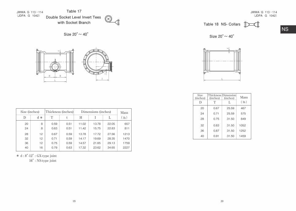
Size (inches) Thickness (inches) Dimensions (inches) Masslb
2024
28323640
88
12121216
0.590.63
0.670.710.750.79
0.510.51
0.590.590.590.63
11.0211.42
13.7814.1714.5717.32
13.7815.75
17.7219.6921.6523.62
22.0522.83
27.5628.3529.1334.65
657811
1213147017592227
*
* d : 8”-12” : GX-type joint16” : NS-type joint
Double Socket Level Invert Tees with Socket Branch
Table 17
Size 20”~ 40”
19
Table 18 NS- Collars
Size(inches)
Thickness(inches)
Dimension(inches) Mass
lb
20
24
28
32
36
40
0.67
0.71
0.75
0.83
0.87
0.91
25.59
25.59
31.50
31.50
31.50
31.50
467
575
849
1052
1252
1459
Size 20”~ 40”
20

Table 19 NS- Flanged Socket
Type 2
Size(inches)
Thickness(inches)
Nominallaying length(inches)
Mass lb
20
24
28
32
36
40
0.59
0.63
0.67
0.71
0.75
0.79
6.69
9.84
9.84
9.84
9.84
9.84
324
437
604
747
906
1065
315
439
611
750
895
1063
377
516
712
893
1063
1299
397
542
809
1071
1283
---
105 psi 145 psi 230 psi 290 psi
Size 20”~ 40”
Detail of flange will conform to JIS G 5527〔105 psi (7.5K) to 290 psi (20K) or AWWA FlangeUpon reguest.
Note :
21
Table 20 NS- Flanged SpigotType 2
Mass lb
20
24
28
32
36
40
0.59
0.63
0.67
0.71
0.75
0.79
29.53
29.53
29.53
29.53
31.50
31.50
362
456
578
710
902
1049
353
456
582
714
891
1047
434
560
783
1034
1276
---
415
536
683
855
1056
1283
Size(inches)
Thickness(inches)
Nominallaying length(inches)
105 psi 145 psi 230 psi 290 psi
Size 20”~ 40”
Detail of flange will conform to JIS G 5527〔105 psi (7.5K) to 290 psi (20K) or AWWA FlangeUpon reguest.
Note :
22
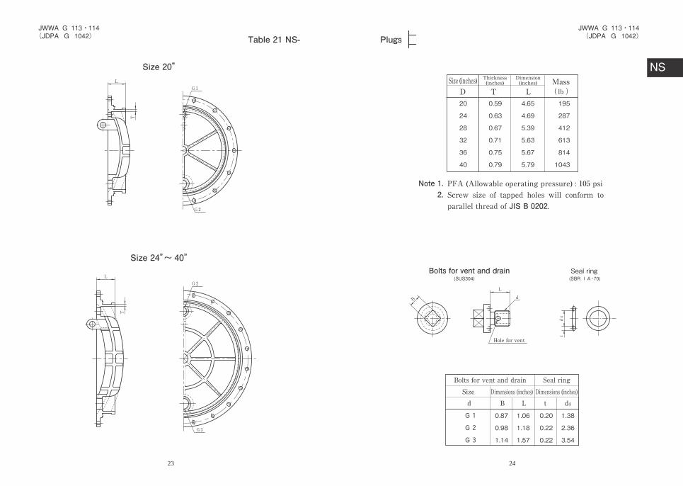
Table 21 NS-
Size 24”~ 40”
Size 20”
23
Plugs
Note 1.2.PFA (Allowable operating pressure) : 105 psiScrew size of tapped holes will conform to parallel thread of JIS B 0202.
Bolts for vent and drain Seal ring
Hole for vent
Bolts for vent and drainSize Dimensions (inches) Dimensions (inches)
Seal ring
Size (inches) Thickness(inches)Dimension(inches) Mass
lb20
24
28
32
36
40
0.59
0.63
0.67
0.71
0.75
0.79
4.65
4.69
5.39
5.63
5.67
5.79
195
287
412
613
814
1043
0.87
0.98
1.14
1.06
1.18
1.57
0.20
0.22
0.22
1.38
2.36
3.54
24

For Fittings (Size12”~ 16”)
Table 22 NS-Jointing Accessories (1)Gland
Number of sides isequal to number of bolts.
Size(inches)
Dimensions (inches) No.of Bolt
Mass
(1 set)lb
12 16 20 24 28
32 36 40
12.87 16.91 20.94 24.99 29.06
33.11 37.17 41.22
16.97 21.10 25.75 29.84 34.49
38.78 43.23 47.52
18.78 22.91 27.56 31.65 36.61
40.91 45.83 50.12
0.91 0.91 0.91 0.91 1.06
1.06 1.30 1.30
0.79 0.87 0.94 0.98 1.02
1.10 1.14 1.18
812141416
202020
28.441.746.757.877.8
93.3117.7138
25
as per double-dashed line.
As-cast hole
For pipes and Fittings (Size 20”~ 40”)
Shape of Size32”and larger,
26

Size12”~ 16”
Table 23 NS-Jointing Accessories (2)Lock Ring
Size(inches)
Dimensions (inches) Mass lb
12 16
0.43 0.43
0.79 0.79
6.31 8.34
3.03.9
Detail of A
Section A
27
Size(inches)
Dimensions (inches) Mass lb
20
24
28
32
36
40
0.69
0.69
0.77
0.81
0.85
0.93
0.98
0.98
1.20
1.20
1.20
1.20
10.31
12.20
14.17
16.18
18.15
20.12
9.9
11.9
19.6
23.1
26.9
37.9
Size 20”~ 40”
28
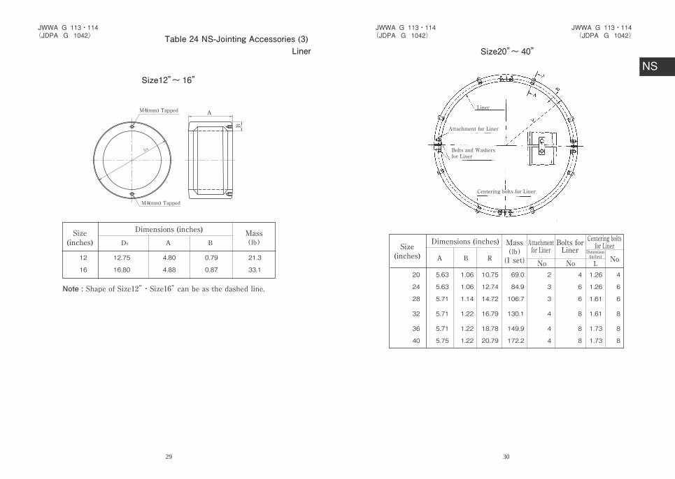
Table 24 NS-Jointing Accessories (3) Liner
Size(inches)
Dimensions (inches) Mass lb
12
16
12.75
16.80
4.80
4.88
0.79
0.87
21.3
33.1
M4(mm) Tapped
M4(mm) Tapped
Size12”~ 16”
Shape of Size12”・Size16” can be as the dashed line.Note :
29
Liner
Attachment for Liner
Centering bolts for Liner
Bolts and Washersfor Liner
Size(inches)
Dimensions (inches) Mass
(1 set)
Attachmentfor Liner
Bolts forLiner
No No NoDimensions(inches)
Centering boltsfor Liner
lb
20
24
28
32
36
40
5.63
5.63
5.71
5.71
5.71
5.75
1.06
1.06
1.14
1.22
1.22
1.22
10.75
12.74
14.72
16.79
18.78
20.79
69.0
84.9
106.7
130.1
149.9
172.2
2
3
3
4
4
4
4
6
6
8
8
8
1.26
1.26
1.61
1.61
1.73
1.73
4
6
6
8
8
8
Size20”~ 40”
30
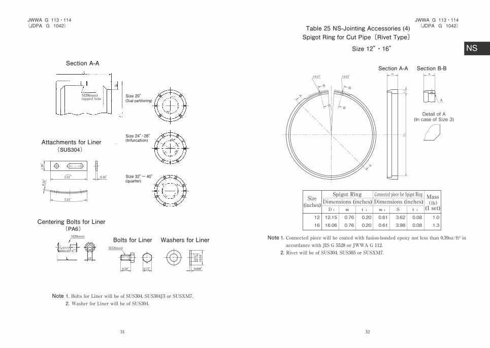
Section A-A
Attachments for Liner
M20(mm)tapped hole (Dual partitioning)
(trifurcation)
(quarter)
Centering Bolts for Liner
Bolts for Liner Washers for LinerM20(mm)
M12(mm)
Size 24”・28”
Size 32”~ 40”
Size 20”
1. Bolts for Liner will be of SUS304, SUS304J3 or SUSXM7.2. Washer for Liner will be of SUS304.
Note
31
Table 25 NS-Jointing Accessories (4)Spigot Ring for Cut Pipe〔Rivet Type〕
Size 12”・16”
Section A-A Section B-B
Detail of A(In case of Size 3)
Size(inches)
Spigot RingDimensions (inches)
Connected piece for Spigot RingDimensions (inches)
Mass
(1 set)lb
12
16
12.15
16.06
0.76
0.76
0.20
0.20
0.61
0.61
3.62
3.98
0.08
0.08
1.0
1.3
1. Connected piece will be coated with fusion-bonded epoxy not less than 0.39oz/ft2 in accordance with JIS G 5528 or JWWA G 112.
2. Rivet will be of SUS304, SUS305 or SUSXM7.
Note
32

Connection Piece for Spigot Ring Rivet
Section C-C
Spigot of Cutting Pipes
Dimension and Tolerance
Flange
Shaft
In case of forming spigot projections by using spigot ring for cut pipe, Class 1 Pipes(D1) for Size3" to Size10" and Class 1 Pipes (D1) or Class PF Pipes (DPF) for Size12" to Size18" will be used, and forming groove of spigot.
Size (inches)
12・16 0.43 +0.0590 0.098 0
-0.0200
-0.079+0.0790 0.13 +0.059-0.0200.55 1.39
33
Spigot Ring Section A-A
Size(inches)
Spigot RingRivet
Connected piece for Spigot RingDimensions (inches)Dimensions (inches)
Mass
(1 set)lb
202428
323640
0.280.280.39
0.390.390.43
0.790.790.98
0.980.981.18
10.20 12.20 14.17
16.18 18.23 20.20
0.12 0.12 0.20
0.20 0.20 0.20
4.374.374.49
4.494.494.49
0.750.750.94
0.940.941.14
3.4 4.0 8.0
9.2 10.3 15.0
0.13 0.13 0.16
0.16 0.16 0.16
1.52 1.52 1.57
1.57 1.57 1.57
Size 20”~ 40”
Rivet will be of SUS304, SUS305 or SUSXM7.Note :
34

Connection piece for Spigot Ring Rivet
Section B-B Flange
Shaft
Note In case of forming spigot projections by using spigot ring for cut pipe, Class S (DS) Pipes, Class 1 (D1) Pipes or Class PF (DPF) Pipes will be used, and forming groove of spigot.
Spigot of Cutting Pipes
Size (inches)
Dimension and Tolerance
20・24
28~36
40
0.87
1.06
1.26
0.12
0.16
0.20
1.57
2.17
1.97
+0.059-0.020
+0.039-0.020 ±0.160
±0.079
35
Size(inches) (mm) (inches) (inches) (inches) No
12
16
20
24
28
32
36
40
M20
M20
M20
M20
M24
M24
M30
M30
1.18
1.18
1.18
1.18
1.42
1.42
1.81
1.81
3.94
4.33
4.92
4.92
5.71
5.71
6.10
6.10
2.56
2.56
3.15
3.15
3.94
3.94
4.33
4.33
8
12
14
14
16
20
20
20
Table 26 NS-Jointing Accessories (5)T-head Bolts and Nuts
Shape of T-head Bolts is unregulated.Note :
36
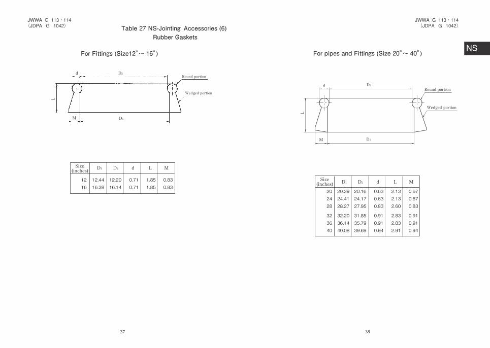
For Fittings (Size12”~ 16”)
Rubber Gaskets
Size(inches)
12 16
12.44 16.38
12.20 16.14
0.71 0.71
1.85 1.85
0.83 0.83
Round portion
Wedged portion
Table 27 NS-Jointing )6( seirosseccA
37
Size(inches)
202428
323640
20.3924.4128.27
32.20 36.1440.08
20.1624.1727.95
31.8535.7939.69
0.630.630.83
0.910.910.94
2.132.132.60
2.832.832.91
0.670.670.83
0.910.910.94
Round portion
Wedged portion
For pipes and Fittings (Size 20”~ 40”)
38

Size(inches) No. of
ProjectionNo. ofProjection
1216
14.2718.35
0.830.83
0.120.12
1418
14.4318.47
0.830.83
0.080.08
810
Table 28 NS-Jointing Accessories (7)Lock Ring Centering Rubbers
Projection
Ring
For Fittings (Size12”~ 16”)
39
For Fittings (Size12”~ 16”)
Table 29 NS-Jointing Accessories (8)Backup Rings
Size(inches)
Dimensions (inches)
1216
6.368.39
0.430.43
0.510.51
40

Fin Body
Cut area
Length of circumscribed circular
Length of circum
scribed circular
Size (inches)
202428
323640
677993
105118131
0.240.240.31
0.310.310.31
0.350.350.35
0.350.350.35
0.430.430.53
0.530.530.53
Dimensions (inches)
For pipes and Fittings (Size 20”~ 40”)
Note 1.2.Circumferential shape of fin can be waved.Cut area can be irregularity.
41