dimensioning and tolerancing by the coloured contacts method
TRANSCRIPT

HAL Id: hal-02008509https://hal.archives-ouvertes.fr/hal-02008509
Submitted on 22 Mar 2019
HAL is a multi-disciplinary open accessarchive for the deposit and dissemination of sci-entific research documents, whether they are pub-lished or not. The documents may come fromteaching and research institutions in France orabroad, or from public or private research centers.
L’archive ouverte pluridisciplinaire HAL, estdestinée au dépôt et à la diffusion de documentsscientifiques de niveau recherche, publiés ou non,émanant des établissements d’enseignement et derecherche français ou étrangers, des laboratoirespublics ou privés.
Dimensioning and tolerancing by the coloured contactsmethodEric Pairel
To cite this version:Eric Pairel. Dimensioning and tolerancing by the coloured contacts method. International Journal ofDesign Sciences and Technology, Europia, 2018, 23 (1), pp.109-123. �hal-02008509�

ISSN 1630 - 7267
Volume 23 Number 1
Pairel É (2018) Dimen-
sioning and tolerancing by
the coloured contacts
method, International
Journal of Design Sciences
and Technology, 23:1 109-
123
Editor-in-Chief:
Khaldoun Zreik
Editors:
Guillaume Besacier
Mithra Zahedi

ISSN 1630 - 7267
© europia Productions, 2018
15, avenue de Ségur,
75007 Paris, France.
Tel (Fr) 01 45 51 26 07 - (Int.) +33 1 45 51 26 07
Fax (Fr) 01 45 51 26 32- (Int.) +33 1 45 51 26 32
E-mail: [email protected]
http://www.europia.org/ijdst
International Journal of Design Sciences and Technology
Volume 23 Number 1
ISSN 1630 - 7267
International Journal of Design Sciences and Technology
Editor-in-Chief: Khaldoun Zreik, University of Paris 8, France
Editors: Guillaume Besacier, University of Paris 8, France
Mithra Zahedi, University of Montreal, Canada
Editorial Board: ACHTEN, Henri (Czech Technical University, Prague, Czech Republic)
AMOR, Robert (University of Auckland, New Zealand)
AOUAD, Ghassan (Gulf University for Science and Technology, Kuwait)
BAX, Thijs (Eindhoven University of Technology, Netherlands)
BECUE, Vincent (Université de Mons, Belgium)
BEHESHTI, Reza (Design Research Foundation, Netherlands)
BONNARDEL, Nathalie (Université d’Aix Marseille, France)
BOUDON, Philippe (EAPLV, France)
BRANGIER, Eric (Université de Lorraine, France)
CARRARA, Gianfranco (Università di Roma La Sapienza, Italy)
DADO, Edwin (NLDA, Netherlands)
EDER, W. Ernst (Royal Military College, Canada)
ESTEVEZ, Daniel (Toulouse University, France)
FARINHA, Fátima (University of Algarve, Portugal)
FINDELI, Alain (Université de Nîmes, France)
GERO, John (George Mason University and University of North Carolina at Charlotte, USA)
GUENA, François (ARIAM-LAREA, ENSA de Paris la Villette, France)
HASSAN, Tarek (Loughborough University Of Technology, UK)
HENSEL, Michael (Oslo School of Architecture and Design, Norway)
HORVATH, Imre (Delft University of Technology, Netherlands)
KATRANUSCHKOV, Peter (Dresden University of Technology, Germany)
KAZI, Sami (VTT, Finland)
KHOSROWSHAHI, Farzad (University of Leeds, UK)
KUILEN, Jan-Willem van de (Munich University of Technology, Germany)
LAUDATI, Patrizia (Université de Valenciennes et du Hainaut Cambrésis, France)
LECLERCQ, Pierre (University of Liège, Belgium)
LEEUWEN, Jos van (Haagse Hogeschool, The Netherlands)
MONTARAS, Lopez de Ramon (ILIIA, Spain)
NEWTON, Sid (University of New South Wales, Australia)
PAOLI, Giovanni de (Université de Montréal, Canada)
REBOLJ, Daniel (University of Maribor, Slovenia)
ROBERTSON, Alec (4D Design Futures Philosopher, UK)
RUITENBEEK, Martinus van de (Delft University of Technology, Netherlands)
SARIYILDIZ, Sevil (Delft University of Technology, Netherlands)
SCHERER, Raimar (Dresden University of Technology, Germany)
SCHMITT, Gerhard (ETH Zurich, Switzerland)
SCIAMMA, Dominique (Strate Collège, France)
SMITH, Ian (EPFL, Switzerland)
TROUSSE, Brigitte (INRIA – Sophia Antipolis, France)
TURK, Žiga (University of Ljubljana, Slovenia)
ZAHEDI, Mithra (University of Montreal, Canada)
ZARLI, Alan (CSTB, France)
ZREIK, Khaldoun (University of Paris 8, France)

International Journal of Design Sciences and Technology, Volume 23 Number 1 (2018) ISSN 1630-7267 109
Editor: Reza Beheshti
Dimensioning and tolerancing by the coloured contacts method
Éric Pairel
University of Savoie Mont Blanc, Laboratoire SYMME, Polytech Annecy-Chambéry, France. Email: [email protected]
The dimensions chain method, very used in mechanical design, makes it possible to determine the dimensions of the parts on which
depend the clearances necessary in the mechanism they constitute. Unfortunately, no method can correctly determine the places in
the mechanism in which these clearances must be introduced and configured. This remains dependent on the intuition of the
designer who must, in addition, make a particular drawing of the mechanism that exaggerates these clearances. Errors are frequent.
The presented coloured contacts method makes it possible to identify, in a systematic and exhaustive way, the functional clearances
for the mechanism and then the dimensions of the parts on which they depend. This method represents a major advance for the
functional dimensioning and tolerancing of the mechanisms. It is accompanied here by a method of calculating tolerance intervals of
distances and dimensions on a relatively complex example.
Keywords: geometry, GD&T, dimensions chain, tolerancing
1 Introduction
For a mechanism to work, there must be clearances between the moving parts and clampings between the
parts to remain bring together. These clearances and these clampings depend on the dimensions of the parts
which are unfortunately subject to variation from a manufactured copy to the other and which therefore
lead to clearances and clampings different between the copies of the mechanism. Therefore, the mechanism
designer must calculate the tolerance intervals of these dimensions so that, despite their variations in these
intervals, the mechanisms are all functional. This step of the mechanical design is called the "geometric
dimensioning and tolerancing, (GD&T)". This step is very important because it can show, for example and
if it is correctly conducted, that the mechanism is not feasible with the precision of the available
manufacturing machines and that its design must be reviewed.
Unfortunately this stage is still poorly controlled by the design offices and eventually leads to very frequent
industrial problems: parts conform to the tolerance indications and which however do not assemble, or the
opposite: non-conforming parts having therefore to be discarded and which yet come together and work
perfectly; resumption of the definition drawings to modify the tolerances ; and even lawsuits between
companies for delivered batches of non-functional parts.
This is explained by the fact that the main method of dimensioning and tolerancing, and almost the only
one used in industry, i.e. the dimensions chain method, is poorly formalized and is also incomplete as we
will show it later.
In mechanical design, the mechanisms are initially modelled and drawn with exact geometries, i.e. without
defects and generally without clearance (gap) or clamping (interference). We will say that this is the
nominal geometry of the mechanism. For example, Figure 1 gives the nominal geometry of an assembly of
a pulley at the end of a shaft without gap or interference between the parts.

110 Dimensioning and tolerancing by the coloured contacts method
This nominal geometry cannot be used by manufacturing because it would lead to a too large proportion of
impossible assemblies because of the inevitable small deviations of the target geometry that generates any
manufacturing on each part. The designer must therefore define, at least, a maximum geometry that must
not exceed the manufactured parts to ensure assembly, and possibly a minimum geometry if he also wants
to guarantee maximum clearance between parts. We will give a more precise definition of the maximum
and minimum geometries in the last part of this paper. Let's just say here that they are relative to certain
dimensions on parts that are critical for their assembly.
Figure 1 Drawing in nominal geometry i.e. without gap nor interference between parts, of the assembly of a pulley at the end of a
shaft
To date, the only method that can determine the dimensions of the shaft, critical for assembly, is the
dimensions chain. It is an essentially manual method, widely used in design, and whose origins are old and
probably multiple.
It is based on the creation of a drawing showing, on the one hand, a particular configuration allowed by the
clearances between parts in the future mechanism and, on the other hand, one or more of these clearances
represented by exaggerated gaps.
For example, Graczyk [7] chose to push all parts of the pulley assembly to the left and to exaggerate a
distance A between the circlips and the washer to allow, according to him, to assemble the future
manufactured parts (Figure 2).
Figure 2 Drawing with an exaggerated gap between two parts
International Journal of Design Sciences and Technology, Volume 23 Number 1 (2018) ISSN 1630-7267 111
This technique of pushing the parts on one side or the other is described in one of the very first books on
dimensioning and tolerancing due to Wade in 1967 [19]. In fact, it can lead to errors as is the case in this
example.
Indeed, once this choice is made, the dimensions chain method consists in looking for the dimensions of
the parts on which the exaggerated distance between the two parts depends. For this one starts from one of
the faces separated by the distance and we try to join the other through the parts and their contacts. Each
part crossed by this mental path provides a dimension on which the distance depends. The vector
representation of the distance and the dimensions makes it possible to establish the algebraic relation
between them (Equation 1 and Figure 2).
A = -w1 -p1 +s1 (1)
Nevertheless, for this example, even if the values of the dimensions w1, p1 or s1 led to a negative distance
A, i.e. to a theoretical interference of the parts, the assembly would be possible anyway by pushing the
circlips to the right (Figure 2).
The distance A is not functional and the dimensions that are deduced neither. The consequence is that some
parts may be discarded because of their dimensions outside their tolerance intervals, even if they could fit
together.
The technique of pushing the parts to the left or to the right is therefore inadequate and can lead to errors.
Anselmetti has suggested in 2012 [1] another technique consisting of moving away or closer two parts in
the aim to introduce a distance between them. This is indeed the correct technique and we will develop it
because Anselmetti does not explain how parts are chosen, or whether the part must move them away or
closer.
The other French works [2, 3, 4, 6, 8, 12, 15, 16, 18] present the dimensions chain method, either on fixed
distances, i.e. between parts immobile between them, which poses no particular problem, either on distances
configured in an unexplained way which does not allow to know what should be done on another
mechanism.
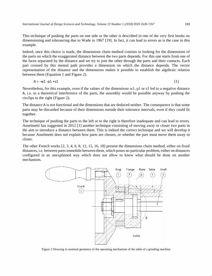
Figure 3 Drawing in nominal geometry of the operating mechanism of the table of a grinding machine
112 Dimensioning and tolerancing by the coloured contacts method
The English books [5, 9, 13, 23] which followed that of Wade [19] ignore this subject preferring to present
the symbolic coding of standardized geometric tolerances. Only that of Henzold, in 2006 [9], presents a
dimensions chain on a simple example that eludes the problem of the choice of the functional distance and
the configuration of the parts.
On the side of scientific publications, few are those relating to the dimensions chain [17, 14, 20, 21, 22]
and all present drawings with distances already identified without explaining how they were.
The coloured contact method, which we present in the following section, makes it possible to identify the
functional distances even in complex mechanisms such as the one that will serve as an example in the
following of this paper.
This is an operating mechanism of the table of a grinding machine represented by its initial design in
nominal geometry i.e. without gap (clearance) or interference (clamping) between the parts (Figure 3). It
consists in a crank (c) connected to screwed shaft (s) which, by screwing into a nut linked to the base and
not shown in the Figure, makes it possible to translate all the parts represented and, particularly, the table
(t) with its plate (p) and its flange (f). The graduated ring (r) can be secured to the crank by a pressure screw
not shown.
The operating requirements are as follows:
− the rigid group formed by the crank and the shaft (and some clamping parts) must be able to freely rotate relative to the rigid
group consisting of the table, the plate and the flange interconnected by clamping screws;
− the shaft is stopped axially by contact of its collet with either the plate (p) to the right, preventing the crank from coming into
contact with the flange (f), or the flange to the left;
− the ring must not be able to be clamped between the flange and the crank when it is pushed towards the table.
2 Coloured contacts method
2.1 Starting point and objectives of the method
To determine the functional dimensions of the parts of a mechanism, i.e. those which are critical for its
assembly and its running, the designer has only the nominal drawing of it, i.e. a drawing without gap nor
interference between the parts in apparent contacts (Figure 3).
The coloured contacts method will allow him to locate the functional clearances in the mechanism;
configure them; and to deduce the functional dimensions of the parts.
The method takes place in three main steps:
− Characterization of all apparent contacts between parts on the nominal drawing according to three types: forbidden, allowed or
imposed. This step makes it possible to explain, directly on the drawing, the intention of the designer concerning the actual
contacts desired between the parts;
− For each forbidden or allowed contact, not already crossed by a path of contacts, plot of its path of contacts;
− For each path, plot of the corresponding dimensions chain and writing the relationship between the distance and the dimensions
of the pieces. This last step corresponds to the dimensions chain method. The first two steps could therefore be seen as missing
links to the current dimensions chain method.
2.2 First step: characterization of apparent contacts
This step consists in characterizing all apparent contacts between parts according to three types:

International Journal of Design Sciences and Technology, Volume 23 Number 1 (2018) ISSN 1630-7267 113
− A contact is imposed if the two parts are clamped against each other by clamping elements or because
of the forces in the functional state of the mechanism considered. There is no distance between the two
parts. For the operating mechanism, the imposed contacts are those between: the flange (f) and the plate
(p); the plate (p) and the table (t); the crank (c) and the shaft (s); washer and crank (c); and finally, the
nut and the washer. They are coloured in green on the nominal design of the mechanism (Figure 4).
− A contact is allowed if the parts can touch each other but must also be able to be separated to make
appear a distance between them. For the operating mechanism, the allowed contacts are: those between
the collet of the shaft and the plate or the flange; and between the ring and the crank or the flange. They
are coloured in orange.
− Finally, a contact is forbidden if, even by bringing the two parts closer together thanks to the clearances,
contact between the two parts must not be possible. In other words, a distance must remain between the
two parts when they are brought closer to one another. For the operating mechanism, this is what is
desired for the apparent contact between the crank and the flange which must not be in contact since the
axial guidance of the shaft must be provided by its collet. It is coloured in red on the Figure 4.
Figure 4 Characterization of apparent contacts between parts
The three colours used here are those of the tricolour light to make it easier to memorize their meanings: in
green, it is imposed to pass; to orange, it's allowed; and red, it's forbidden. At this stage all apparent contacts
have been reviewed, which guarantees the completeness of analysis of the mechanism by the method.
2.3 Second step: configuration of each allowed or forbidden contact, not crossed by a path of contacts,
and its path of contacts
The red and orange lines on the drawing of the nominal mechanism (Figure 4) should be considered as gaps
between parts for this second stage. We give a representation on Figure 5 to insist on this point, but this
figure is not at all obligatory: the nominal drawing with the coloured apparent contacts is sufficient.
It is now a question of configuring each forbidden or allowed contact by decreasing or, respectively, by
increasing, the distance between the two parts. Doing so, the both parts will rely on the other parts of the
mechanism by their imposed or allowed contacts with them.
114 Dimensioning and tolerancing by the coloured contacts method
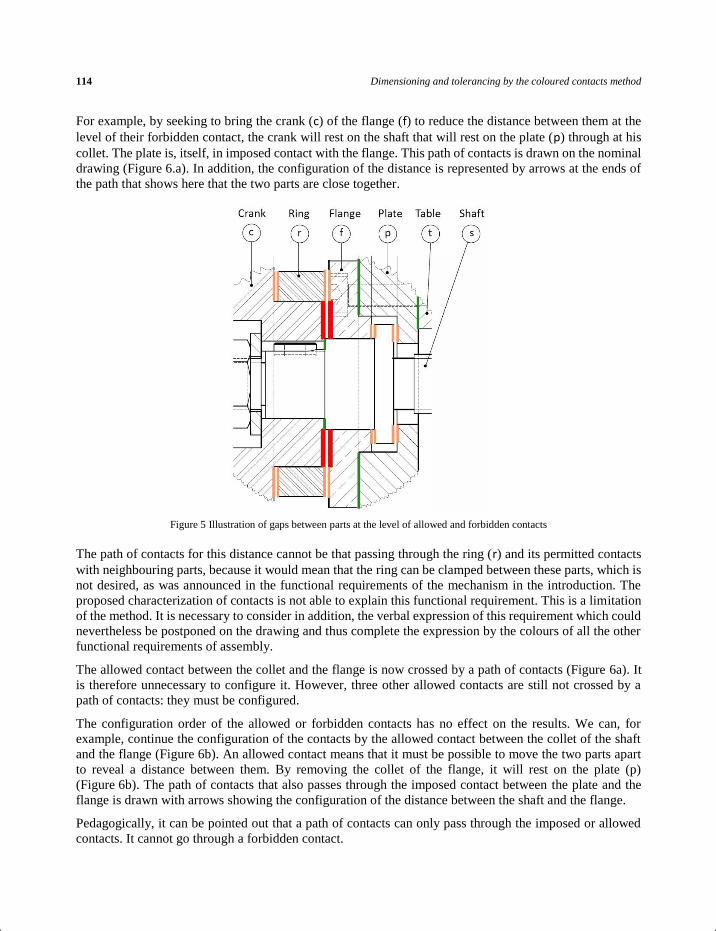
For example, by seeking to bring the crank (c) of the flange (f) to reduce the distance between them at the
level of their forbidden contact, the crank will rest on the shaft that will rest on the plate (p) through at his
collet. The plate is, itself, in imposed contact with the flange. This path of contacts is drawn on the nominal
drawing (Figure 6.a). In addition, the configuration of the distance is represented by arrows at the ends of
the path that shows here that the two parts are close together.
Figure 5 Illustration of gaps between parts at the level of allowed and forbidden contacts
The path of contacts for this distance cannot be that passing through the ring (r) and its permitted contacts
with neighbouring parts, because it would mean that the ring can be clamped between these parts, which is
not desired, as was announced in the functional requirements of the mechanism in the introduction. The
proposed characterization of contacts is not able to explain this functional requirement. This is a limitation
of the method. It is necessary to consider in addition, the verbal expression of this requirement which could
nevertheless be postponed on the drawing and thus complete the expression by the colours of all the other
functional requirements of assembly.
The allowed contact between the collet and the flange is now crossed by a path of contacts (Figure 6a). It
is therefore unnecessary to configure it. However, three other allowed contacts are still not crossed by a
path of contacts: they must be configured.
The configuration order of the allowed or forbidden contacts has no effect on the results. We can, for
example, continue the configuration of the contacts by the allowed contact between the collet of the shaft
and the flange (Figure 6b). An allowed contact means that it must be possible to move the two parts apart
to reveal a distance between them. By removing the collet of the flange, it will rest on the plate (p)
(Figure 6b). The path of contacts that also passes through the imposed contact between the plate and the
flange is drawn with arrows showing the configuration of the distance between the shaft and the flange.
Pedagogically, it can be pointed out that a path of contacts can only pass through the imposed or allowed
contacts. It cannot go through a forbidden contact.

International Journal of Design Sciences and Technology, Volume 23 Number 1 (2018) ISSN 1630-7267 115
Figure 6 Plot of paths of contacts established by configured distances of forbidden and allowed contacts
There are still two allowed contacts: those of the ring with the crank and the flange. One of them could be
configured by increasing the distance between the two parts but that would not guarantee the impossibility
of tightening the ring between the crank and the flange. To do this, it is necessary to verify that by pushing
the crank towards the flange, a distance remains in one of two contacts, for example that of the ring with
the crank. The ring itself is pushed towards the flange to lean on it. The flange must be considered as fixed
so that the crank and the ring can be pushed on it. This is represented by a point on the path of contacts
(Figure 6c). The arrows at the ends of this path show the configuration of the distance between the crank
and the ring.
The distance to be considered is not therefore the increased distance, as is normally the case for an allowed
contact, but a distance obtained by pulling the face of the crank towards the space between it and the ring
whose face must be pushed. We call this distance, a pull-thrust distance. This case is not explained by the
colours of the contacts and it is a limit of the proposed method as already indicated. Nevertheless, on the
one hand this case is quite rare and on the other hand it is more easily identified with the proposed method.
It also shows that it is necessary to generalize the description of the distances in the mechanisms: for a
forbidden contact, the distance to be studied is a pulled-pulled distance whereas for an allowed contact, it
is, in most cases, pushed-pushed but it can sometimes be pulled-pushed or pushed-pulled (Figure 7).
Figure 7 The four types of distance between parts

116 Dimensioning and tolerancing by the coloured contacts method
For the operating mechanism, all allowed and forbidden contacts are now in, at least, one path of contacts:
the contact configuration process is therefore complete and there are only three functional distances for the
assembly of this mechanism whereas at first glance, one would have thought that there would have been
more.
2.4 Third step: drawing the dimensions chain of each functional distant
This step is much simpler than the previous one and corresponds to the current dimensions chain method.
It consists in following each path of contacts, in one direction or the other, to determine the dimensions of
the parts on which the distance that this path configures (Figure 8).
Figure 8 Plot of dimensions chains of each functional distance
The distance and the dimensions are represented as vectors so that the distance-vector, traditionally
represented by a double straight lines arrow, is equal to the sum of the dimension-vectors, traditionally
represented by a single straight-line arrow. Their projection then makes it possible to obtain the relations
between them:
(2)
(3)
(4)
These equations have the following general form:
(5)
where is the coefficient of influence of the dimension xi on Y (-1 or +1 for equations 2 to 4)
A f1 p1 s1
B f2 p1 s2
C r1 f1 p1 s1 c1
Y xixii
xi

International Journal of Design Sciences and Technology, Volume 23 Number 1 (2018) ISSN 1630-7267 117
These relationships are necessary for calculating tolerance intervals for distances and dimensions in the
next section. This next step is not a part of the coloured contact method but is its logical continuation and
allows, in addition, to verify its efficiency.
3 Calculation of tolerance intervals of distances and dimensions
Whether the distance is of the type pulled-pulled, pushed-pushed or pulled-pushed, a minimum clearance
must be guaranteed in a forbidden contact or in an allowed contact. It is therefore enough to choose a
minimum positive value for each functional distance identified by the coloured contact method. These
values can be chosen independently of each other.
For the operating mechanism, we have chosen relatively large minimum values so that they are visible on
the median geometry presented in Figure 11, but they could have been smaller or even zero (equations 6 to
8. The unit of these lengths may be the millimetre or the inch of the imperial system):
MinA = 0.300 (6) MinB = 0.100 (7) MinC = 0.300 (8)
In mechanical design, the maximum values of the distances are more difficult to choose because they give
the maximum clearances between the parts that one wishes always the weakest possible. Furthermore, by
setting these maximum values, in addition to the minimum values, their tolerance intervals are fixed, and
the calculations become more complicated and can especially lead to intolerable tolerances in manufacture.
Yet it is often the way that the dimensions chain method is taught.
Table 1 Crossed table of tolerance intervals (known or chosen values in black and calculated in blue)
It seems to us simpler and more pragmatic to first fix the tolerances of the functional dimensions considering
the manufacturing processes of the parts or, if they are not known, by choosing standard ISO quality levels
[10] and then deduce the maximum values of the distances.
To carry out these calculations, we use here a crossed table relatively well known in companies but oddly
absent from the publications on dimensioning and tolerancing (Table 1).
The dimension chains are presented, in rows, by the influence coefficients of the several functional
dimensions. For instance, the dimensions chain of the distance A, depends, respectively on the coefficients
1, -1 and -1, on the dimensions s1, f1 and p1.
118 Dimensioning and tolerancing by the coloured contacts method
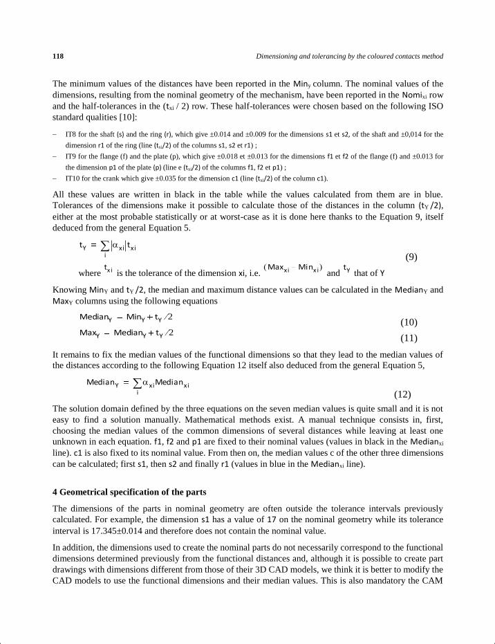
The minimum values of the distances have been reported in the Miny column. The nominal values of the
dimensions, resulting from the nominal geometry of the mechanism, have been reported in the Nomixi row
and the half-tolerances in the (txi / 2) row. These half-tolerances were chosen based on the following ISO
standard qualities [10]:
− IT8 for the shaft (s) and the ring (r), which give ±0.014 and ±0.009 for the dimensions s1 et s2, of the shaft and ±0,014 for the
dimension r1 of the ring (line (txi/2) of the columns s1, s2 et r1) ;
− IT9 for the flange (f) and the plate (p), which give ±0.018 et ±0.013 for the dimensions f1 et f2 of the flange (f) and ±0.013 for
the dimension p1 of the plate (p) (line e (txi/2) of the columns f1, f2 et p1) ;
− IT10 for the crank which give ±0.035 for the dimension c1 (line (txi/2) of the column c1).
All these values are written in black in the table while the values calculated from them are in blue.
Tolerances of the dimensions make it possible to calculate those of the distances in the column (tY /2),
either at the most probable statistically or at worst-case as it is done here thanks to the Equation 9, itself
deduced from the general Equation 5.
(9)
where is the tolerance of the dimension xi, i.e. and that of Y
Knowing MinY and tY /2, the median and maximum distance values can be calculated in the MedianY and
MaxY columns using the following equations
(10)
(11)
It remains to fix the median values of the functional dimensions so that they lead to the median values of
the distances according to the following Equation 12 itself also deduced from the general Equation 5,
(12)
The solution domain defined by the three equations on the seven median values is quite small and it is not
easy to find a solution manually. Mathematical methods exist. A manual technique consists in, first,
choosing the median values of the common dimensions of several distances while leaving at least one
unknown in each equation. f1, f2 and p1 are fixed to their nominal values (values in black in the Medianxi
line). c1 is also fixed to its nominal value. From then on, the median values c of the other three dimensions
can be calculated; first s1, then s2 and finally r1 (values in blue in the Medianxi line).
4 Geometrical specification of the parts
The dimensions of the parts in nominal geometry are often outside the tolerance intervals previously
calculated. For example, the dimension s1 has a value of 17 on the nominal geometry while its tolerance
interval is 17.345±0.014 and therefore does not contain the nominal value.
In addition, the dimensions used to create the nominal parts do not necessarily correspond to the functional
dimensions determined previously from the functional distances and, although it is possible to create part
drawings with dimensions different from those of their 3D CAD models, we think it is better to modify the
CAD models to use the functional dimensions and their median values. This is also mandatory the CAM
tY xi txii
tx i Maxxi Minx i( ) tY
MedianY MinY tY 2
MaxY MedianY tY 2
MedianY xiMedianxii

International Journal of Design Sciences and Technology, Volume 23 Number 1 (2018) ISSN 1630-7267 119
process. Thus, their drawings can be made by projection of their CAD models and their dimensions. For
the shaft, the two functional dimensions were created in its CAD model in median geometry and were
displayed on its drawing enclosed in a frame: 17.345 and 5.865 (Figure 9).
Figure 9 Drawing of (partial) definition of the shaft with these toleranced functional dimensions
These two dimensions cannot be directly toleranced by a dimensional tolerance interval because, for the
dimension of 17.345, this would have no standardized meaning, and for the dimension of 5.865, this would
not completely constrain the right flat face of the collet.
On the contrary, the standardized geometrical tolerancing makes it possible to completely constrain all the
functional faces. Several solutions are nevertheless possible. The most direct is to specify the tolerance
interval of each functional dimension as a gauge of two tolerance zones of width equal to half tolerance and
distant from the median value of the dimension. For the dimension 17.345, this gives the virtual gauge
given in Figure 10. Both manufactured faces must be lie inside those two zones.
Figure 10 Tolerance interval of s1, specified as a gauge of two tolerance zones
By taking inspiration from examples of indication of ISO standards, we can encode this gauge in the form
of a location tolerance of a "collection of zones". This is indicated by the letters CZ in the tolerance frame
(Figure 9) in accordance with ISO1101 of 2017 [11].
With a different tolerance value, the tolerance interval on dimension 5.865 is coded in the same way In
addition, these toleranced faces must be as perpendicular as possible to the two cylindrical surfaces which
first position the shaft in the mechanism. These two cylindrical surfaces have therefore been taken as a
common reference for the two location tolerances. This is specified in the frames by the indication A-B (Figure 9). Similar tolerancing must be done for the other parts of the mechanism.
On the other hand, the CAD assembly of the parts in median geometry reveals gaps between the parts that
can be measured and displayed on the mechanism drawing. For the operating mechanism, the three
functional distances are correctly configured when the right face of the collet is resting on the plate as we

120 Dimensioning and tolerancing by the coloured contacts method
saw in section 2.3. It is thus that the CAD assembly of the median parts has been realized (Figure 11) and
the measured distances on this CAD assembly correspond to the calculated median values in Table 1, which
confirms the good determination of the functional dimensions allowed by the coloured contact method, the
correct calculation of the tolerance intervals and finally the good creation of the median geometries of the
parts.
Figure 11 Median geometry of the mechanism showing functional distances in median value
The 3D CAD modelling of the mechanisms enables also the generation of the maximum geometries of the
mechanism, i.e. the geometries giving the minimum value at one or more functional distances. This suffices
to give the minimum value to each dimension having a positive influence on the distance, and the maximum
value if its influence is negative. For instance, the minimum value of the distance A is obtained by the
minimum value of the dimension s1 and the maximum values of the dimensions f1 and p1 (Table 1).
However, one dimension can have a positive influence on one distance and a negative on another. This is
the case of the dimension p1, which has a negative influence on B and positive on the two others (Table 1).
It is possible for this example to generate a first maximum geometry for A and C and a second for B. The
same goes for the minimum geometries. These extreme geometries make it possible to observe the
efficiency of the coloured contact method.
5 Nominal, median, minimum and maximum geometry
With 3D CAD it is easy to generate different geometries by changing dimension values. Among all these
possible geometries, we have already defined the nominal and median geometries of a mechanism:
− the nominal geometry is that having neither gap (clearance) nor interference (clamping) between the parts of the CAD mechanism.
This is usually the first created by the designer since it precedes the determination of distances and functional dimensions;
− the median geometry is that obtained by giving to the functional dimensions of the parts, the median value of their tolerance
intervals and by correctly configuring as many functional distances as possible in the mechanism. Indeed, as we have shown, the
functional distances are often configured distances, that is to say, to consider when the faces that they connect are either pushed
or pulled, which configures the position of the parts of the mechanism (section 2.3). However, it is quite rare for all distances to
be correctly configured by a single configuration of parts, unlike the case of the mechanism used as an example. There are

International Journal of Design Sciences and Technology, Volume 23 Number 1 (2018) ISSN 1630-7267 121
therefore often several possible configurations of the mechanism in median geometry that lead to the median values on certain
distances and not the others.
It is the same for the maximum and minimum geometries we now define
We call, maximum geometry, the geometry giving the most material to the parts (in most cases) and leading
to the minimum values of the correctly configured functional distances, i.e. the minimum clearances and
the maximum clampings.
Conversely, the minimum geometry is that giving the least material to the parts (in most cases) and which
leads to the maximum values of the correctly configured functional distances, i.e. the maximum clearances
and the minimum clampings.
The creation of these extreme geometries can ensure clearances and clampings in the worst cases. It must
be kept in mind that these worst cases are nevertheless very few statistically probable.
As an example, we give in Figure 12 the maximum geometry for A and C. It is not for B, even if this distance
is correctly configured, because the dimension p1 has opposite influences on these distances (Table 1). The
measurement of these distances on this geometry again confirms the correct calculation of tolerance
intervals on good dimensions since A and C are indeed at the initially chosen minimum values. B takes a
higher value in its tolerance interval [0.100; 0.170].
Figure 12 Maximum geometry of the mechanism for distance A and C (but not for B which is not at its minimum value)
These definitions are original as is the coloured contacts method from which they derive. The ISO standards
on the geometrical specification have not yet defined these geometries. In fact, some use the word "nominal
geometry" but without defining it. In companies, the median geometry is well known. It is usually called
the medium geometry.

122 Dimensioning and tolerancing by the coloured contacts method
6 Conclusion
The coloured contacts method makes it possible to identify exhaustively the distances between parts, critical
for the assembly and the functioning of the mechanisms. To our knowledge, this is the first time such a
method is proposed.
These distances configure the contacts between parts as they are either pulled-pulled, pushed-pushed,
pulled-pushed or pushed-pulled distances. The plots of the paths of contacts that they establish make it
possible to identify the dimensions of the parts on which they depend. These two concepts greatly improve
the today dimensions chain method.
The coloured contacts method is therefore a major advance for the functional dimensioning of the
mechanisms. Its computerization is possible: the designer would only have to specify the nature of the
apparent contacts between parts in the nominal CAD model of the mechanism so that distances and
functional dimensions could be automatically determined. This remains to be developed.
We have also presented a method for calculating tolerance intervals of distances and functional dimensions,
based on a cross-table well known in the industry but curiously missing in the literature on functional
dimensioning. This table also makes it possible to determine the values of the dimensions giving the
maximum or the minimum geometry for one or more distances.
These two methods were tested on a similar mechanism to the one used in this paper and whose parts were
made by three-dimensional printing with a rapid prototyping machine. The printing of the parts in nominal
geometry led to an impossible assembly while those in the median geometry led to fully assembling and
functioning parts. To do this, it has been necessary to consider the random dispersion of each type of
dimension produced by the prototyping machine as well as the systematic deviations that it creates on each
of them.
We have also shown that even if the dimension chain is based on a geometric model whose only defects
are the dimensional deviations in one direction, it is quite possible to specify the tolerance intervals in the
form tolerance zones limiting all geometric deviations in accordance with standardized tolerancing.
Finally, we have defined four particular geometries of parts and mechanisms that must be distinguished in
order to geometrically specify the products: the nominal, minimum, median and maximum geometries.
Acknowledgment
We thank Max Giordano, Professor emeritus at the University Savoie Mont Blanc et Vincent Simoneau,
director of the mechanical design office " Cortes ingénierie " for the improvements they have made to this
paper.
Bibliography
[1] Anselmetti, B., 2012, Tolérancement Volume 2 : Méthode de cotation fonctionnelle, Lavoisier
[2] Bourdet, P., & Schneider, F., 2007, Spécification géométrique des produits - Cotation et tolérancement ISO, Dunod
[3] Bullerwell, J., Barbey, Y., 1977, Cours de cotation fonctionnelle. 2, Chaînes de cotes : enseignement programmé :
formation continue, cours de promotion, CAP, BEP, André Casteilla., Paris
[4] Chevalier, A., 2003, Guide du dessinateur industriel, Hachette, Technique
[5] Cogorno, G. R., 2011, Geometric dimensioning and tolerancing for mechanical design - A self-teaching guide to the
ASME Y14.5-1994 standards, McGraw-Hill
[6] Dufailly, J., & Poss, M., 2017, Cotation fonctionnelle, chaines de cotes, optimisation des tolerances., Ellipses
(Formations)

International Journal of Design Sciences and Technology, Volume 23 Number 1 (2018) ISSN 1630-7267 123
[7] http://www.graczyk.fr/lycee/AAA/htm/res/ci3/c_chaine/txt.htm
[8] Hazard, C., 2012, Mémotech de dessin technique, Casteilla, Paris
[9] Henzold, G., 2006, Geometrical dimensioning and tolerancing for design, manufacturing and inspection: a handbook
for geometrical product specifications using ISO and ASME standards, Butterworth-Heinemann.
[10] ISO 286-1:2010, Geometrical product specifications (GPS) — ISO code system for tolerances on linear sizes — Part
1: Basis of tolerances, deviations and fits
[11] ISO 1101:2017, Geometrical product specifications (GPS) -- Geometrical tolerancing -- Tolerances of form,
orientation, location and run-out
[12] Linares, J.-M., 1996, "Contribution à l’etude de la cotation fonctionnelle par une approche systemique", Ph.D. thesis,
INSA Lyon, France
[13] Meadows, J. D., 1995, Geometric dimensioning and tolerancing: applications and techniques for use in design,
manufacturing, and inspection, M. Dekker
[14] Peng, H. P., Jiang, X. Q., & Liu, X. J., 2008, "Concurrent optimal allocation of design and process tolerances for
mechanical assemblies with interrelated dimension chains". International Journal of Production Research, 46(24),
6963–6979
[15] Padilla P., Anselmetti B., Mathieu L., 1986, Raboyeau M., Production mécanique, fabrication générale, Dunod
[16] Ricordeau, A., 1984, Cahier no. 4, Exercices Rapides de Cotation Fonctionnelle, Casteilla, Paris
[17] Singh, P. K., Jain, S. C., & Jain, P. K., 2005, "Advanced optimal tolerance design of mechanical assemblies with
interrelated dimension chains and process precision limits", Computers in Industry, 56(2), 179–194
[18] Villars F., 1999, Cotation fonctionnelle, Techniques de l’Ingenieur BM 7020
[19] Wade, O. R., 1967, Tolerance Control in Design and Manufacturing, Industrial Press
[20] Wang, N., & Ozsoy, T. M., 1993, "Automatic Generation of Tolerance Chains from Mating Relations Represented in
Assembly Models", Journal of Mechanical Design, 115(4), 757–761
[21] Wang, X., Sun, C., Yao, Y., & Liang, L., 2014, "Extension of the definition of tolerance and an application thereof in
the calculation of dimension chains", The International Journal of Advanced Manufacturing Technology, 71(5–8),
1069–1076
[22] Xu, H. H., & Liu, X. A., 2014, "Analysis for Assembly Dimension Chain of RV Reducer", Applied Mechanics and
Materials, 635–637, 1826–1829
[23] Zhang, H.-C., 1997, Advanced tolerancing techniques, John Wiley & Sons

124 Dimensioning and tolerancing by the coloured contacts method

International Journal of Design Sciences and Technology Design Sciences, Advanced Technologies and Design Innovations Towards a better, stronger and sustainable built environment
Aims and scope
Today’s design strongly seeks ways to change itself into a more competitive and innovative discipline
taking advantage of the emerging advanced technologies as well as evolution of design research disciplines
with their profound effects on emerging design theories, methods and techniques. A number of reform
programmes have been initiated by national governments, research institutes, universities and design
practices. Although the objectives of different reform programmes show many more differences than
commonalities, they all agree that the adoption of advanced information, communication and knowledge
technologies is a key enabler for achieving the long-term objectives of these programmes and thus
providing the basis for a better, stronger and sustainable future for all design disciplines. The term
sustainability - in its environmental usage - refers to the conservation of the natural environment and
resources for future generations. The application of sustainability refers to approaches such as Green
Design, Sustainable Architecture etc. The concept of sustainability in design has evolved over many years.
In the early years, the focus was mainly on how to deal with the issue of increasingly scarce resources and
on how to reduce the design impact on the natural environment. It is now recognized that “sustainable” or
“green” approaches should take into account the so-called triple bottom line of economic viability, social
responsibility and environmental impact. In other words: the sustainable solutions need to be socially
equitable, economically viable and environmentally sound.
IJDST promotes the advancement of information and communication technology and effective application
of advanced technologies for all design disciplines related to the built environment including but not limited
to architecture, building design, civil engineering, urban planning and industrial design. Based on these
objectives the journal challenges design researchers and design professionals from all over the world to
submit papers on how the application of advanced technologies (theories, methods, experiments and
techniques) can address the long-term ambitions of the design disciplines in order to enhance its competitive
qualities and to provide solutions for the increasing demand from society for more sustainable design
products. In addition, IJDST challenges authors to submit research papers on the subject of green design.
In this context “green design” is regarded as the application of sustainability in design by means of the
advanced technologies (theories, methods, experiments and techniques), which focuses on the research,
education and practice of design which is capable of using resources efficiently and effectively. The main
objective of this approach is to develop new products and services for corporations and their clients in order
to reduce their energy consumption.
The main goal of the International Journal of Design Sciences and Technology (IJDST) is to disseminate
design knowledge. The design of new products drives to solve problems that their solutions are still partial,
and their tools and methods are rudimentary. Design is applied in extremely various fields and implies
numerous agents during the entire process of elaboration and realisation. The International Journal of
Design Sciences and Technology is a multidisciplinary forum dealing with all facets and fields of design.
It endeavours to provide a framework with which to support debates on different social, economic, political,
historical, pedagogical, philosophical, scientific and technological issues surrounding design and their
implications for both professional and educational design environments. The focus is on both general as
well as specific design issues, at the level of design ideas, experiments and applications. Besides examining
the concepts and the questions raised by academic and professional communities, IJDST also addresses the
concerns and approaches of different academic, industrial and professional design disciplines. IJDST seeks
to follow the growth of the universe of design theories, methods and techniques in order to observe, to
interpret and to contribute to design's dynamic and expanding sciences and technology. IJDST will examine

design in its broadest context. Papers are expected to clearly address design research, applications and
methods. Conclusions need to be sufficiently supported by both evidence from existing research (reference
to existing design research knowledge) as well as strong case-studies from any design discipline. A paper
must contain at least one chapter on research questions, methodology of research and methods of analysis
(the minimum length is 1500 words). The concluding chapter (the minimum length is 1000 words) will
summarise the paper and its results. The concluding chapter also examines and discuss applications,
advantage, shortcomings and implications of the investigation for both professional and educational design
communities as well as for the people and the society. Also, authors are also encouraged to include in this
chapter a discussion of the possible future research that is required or is possible in order to enhance the
research findings.
The papers considered for IJDST cover a wide range of research areas including but not limited to the
following topics: Design research, design science, design thinking, design knowledge, design history,
design taxonomy, design technology, design praxeology, design modelling, design metrology, design
axiology, design philosophy, design epistemology, design pedagogy, design management, design policy,
design politics, design sociology, design economics, design aesthetics, design semantics, design decision-
making, design decisions, design evaluation, design sustainability, design logic, design ontology, design
logistics, design syntaxis, design ethics, design objective, design responsibility, design environment, design
awareness, design informatics, design organization, design communication, design intelligence, design
evaluation, design education, design theories, design techniques, design methods, design operations, design
processes, design products, design users, design participation, design innovation, design inspired by nature,
design case studies, design experiments, etc.
The International Journal of Design Sciences and Technology is devoted to further exploration of all
themes and issues that are directly or indirectly relevant to the exploration, introduction, discussion of
design sciences and technology, cross referencing domains and any other themes emerging in the future.
Instructions for Authors and Review Process
Pre-review Stage (Editor Global Review): Papers can only be considered for review when they deal with a
subject relevant to the content of the journal. In addition, all papers submitted must follow the journal’s
paper structure and author instructions before they can be considered for review. These instructions also
affect the content of the paper. The preferred size of a paper is about 10000 words (The minimum length
of a paper is about 7000 words). The title must not be longer than seven words. Subtitles are not permitted.
The maximum length of the abstract is 150 words. The paper must contain an introductory chapter with
extensive literature review of similar research (the minimum length of the introduction chapter is about
1000 words). The paper devotes at least one chapter to detailed discussion of research questions, research
analysis and research contributions (the minimum length of this chapter is about 1000 words). The
conclusion will summarise the research and its results. In addition, this chapter includes a detailed
discussion of applications, advantage, shortcomings and implications of the investigation as well as future
research for both design professionals and the design education (the minimum length of conclusions is
about 1000 words). Submit a paper at this stage as PDF.
Review Stage (Peer Review): Only papers meeting all IJDST requirements can be considered for review.
All papers are reviewed by at least two expert reviewers. The main author of a reviewed and accepted paper
will be notified with instructions to resubmit the paper. All reviewed and accepted papers have to be
resubmitted, implementing reviewers and editors’ comments and/or suggestions. Only accepted papers
conforming to instructions will be considered for publication in the International Journal of Design Sciences
and Technology. A paper should follow the IJDST paper structure. The review process will be repeated
until all requirements are met.

The first page of the paper must contain the full title of the paper as well as the Name+Surname (no initials),
affiliation, address, telephone, fax and email of the corresponding author to whom all correspondence to be
directed. Also mention the Name+Surname (no initials), affiliation, postal address, telephone, fax and email
of the co-authors (if any).
The second page contains the full title of the paper (maximum 7 words), the sub-title is not permitted, an
abstract of about 50 to 150 words summarising the content of the paper and 3-5 keywords for the purpose
of indexing (the use of references in the abstract is discouraged). The length of a paper is about 7000 words
(10000 words is preferred). Short papers will not be accepted for publication and have to be resubmitted.
The use of Footnotes is permitted (maximum length is about 50 words). Footnotes should be numbered
consecutively. For instance: [[17 A ‘footnote’ reflects additional information, a reference or the URL of a
website]].
The paper will be written in the UK English. It will be single-spaced with 30 mm margins on all sides
(paper size A4). Use Times New Roman for the main body of text (size 10), figures (size 8) or tables (size
8). The use of Bold, Italics, ALL CAPS, SMALL CAPS, etc. is discouraged. All chapters should be
numbered consecutively (more than two level sub-headings is discouraged). All Figures and Tables with
their respective captions should be numbered consecutively. They should each, be placed on a separate
page, at the end of the paper. Give an approximate insertion point for figures and tables, between double
square brackets. For instance: [[insert Figure 5]]. You will be asked to resubmit tables, figures and images
if necessary. The paper must be submitted in plain text. Do not layout your paper. Do not use any styles or
any automatic layout system. Please do not use ‘Track Changes’.
All tables should be clearly referred to in the main body of text as Table 1, Table 2, etc. All Figures should
be clearly referred to in the main body of text as Figure 1, Figure 2, etc. Line drawings should be of good
quality. Use light background if possible (white is preferred). Photographs and screen-shots should also be
submitted separately as JPEG files (use high resolution for better results). Authors should prepare high
quality figures and drawings. The use of colours in your illustrations is permitted although the hardcopy of
the journal is not published in colour. Maximum width and height of a figure are respectively 150 mm and
190 mm. Maximum width and height of a table are respectively 115 mm and 170 mm. All Equations will
be numbered consecutively and should be clearly mentioned in the main body of text.
All references will appear at appropriate places in the main body of text. References are collected at the
end of the paper, arranged in alphabetical order (numbered consecutively) by the first author's surname,
followed by initials. All authors should be mentioned. Dates will appear between brackets after the authors'
name(s). This is followed by the title of the book, name of the publisher, place of publication and page
numbers (if applicable). To refer to a journal paper, add the full title of the journal followed by
Volume:Number and page(s). The number of references to the author’s own previous publications will not
exceed 5% of the total number of references. References that are not mentioned in the main body of text
are not allowed. Examples of references to a book, a journal or a website are shown below:
[1] Beckett KL and Shaffer DW (2004) Augmented by Reality: The Pedagogical Praxis of Urban Planning as a
Pathway to Ecological Thinking, University of Wisconsin, Madison [2] Blackman, DA (2001) Does a Learning Organisation Facilitate Knowledge Acquisition and Transfer?
Electronic Journal of Radical Organization Theory, 7:2 [www.mngt.waikato.ac.nz/Research/ ejrot/Vol7_1/Vol7_1articles/blackman.asp]
[3] Buxton, W (1997) Living in Augmented Reality: Ubiquitous Media and Reflective Environments. In: Finne K, Sellen A and Wilber S eds, Video Mediated Communication, Erlbaum, Hillsdale NJ, 363-384
[4] Dixon, NM (2000) Common Knowledge: How companies thrive by sharing what they know, Harvard
Business School Press, Boston, MA
[5] Djenidi H, Ramdane-Cherif A, Tadj C and Levy N (2004). Generic Pipelined Multi-Agents Architecture for Multimedia Multimodal Software Environment, Journal of Object Technology, 3:8, 147-169
[6] Gorard, S and Selwynn, N (1999) Switching on to the learning society? Questioning the role of technology in widening participation in lifelong learning, Journal of Education Policy, 14:5, 523-534
[7] World Bank (2002) Social assessment as a method for social analysis, World Bank Group [www.worldbank.org/gender/resources/assessment/samethod.htm]
The definitive paper is submitted as plain text MS Word file for the PC (MS Word RTF format for the
Apple). In addition, a formatted version of the paper (including images and tables at their approximate
places) will be submitted in PDF format. All figures must be submitted separately in high resolution jpg
format. Submit your paper as an email attachment to: [email protected].
Author(s) of an accepted paper have to complete, sign and return a Copyrights Transfer Form to the
publisher. This copyrights transfer assignment will ensure the widest possible dissemination of information.
Papers published in the International Journal of Design Sciences and Technology cannot be published
elsewhere, in any form (digital, paper-based or otherwise) without a prior written permission from the
publisher.
The author(s) are responsible for obtaining permission to utilize any copyrighted material. For more details
about this subject, please contact the publisher at an early stage.
A paper can be rejected at any stage if the requirements are not met. The decision of the Editor-in-Chief on
all matters related to the International Journal of Design Sciences and Technology including the review
process, publication of papers, etc. is final and cannot be disputed.
There is no deadline for the publication of an accepted paper that will be published online within one to
four months after the final re-submission is accepted. The hardcopy book of the volume will be published
when 8 papers are published online. The corresponding author of a paper published in the International
Journal of Design Sciences and Technology will receive a digital copy of the author’s paper free of charge.
Hard copies of any individual paper (minimum 100 copies) and the hardcopy of the IJDST Volume
(containing 8 papers published online) can be purchased from the publisher (ask for an invoice from the
publisher [email protected]).

International Journal of Design Sciences and Technology
How to Order IJDST-online You can view and download a digital version of individual papers free of charge from the journal’s website.
IJDST Hardcopies Hardcopies of individual papers (minimum order 100 copies) and volumes (minimum order is one single copy of the book containing 2 issues) can be ordered directly from Europia Productions. You need to send your Request for an Invoice (preferably by email, Fax or letter) indicating details of your order and the quantities. Please provide your full name and initials, postal address, email and telephone number. An invoice will be sent to you indicating the total amount of your order, the cost of packing/postage and method of payment.
Individual Subscription IJDST Hardcopies
Individuals can subscribe to receive a hardcopy of the book containing 2 issues for € 200.00 (incl. 5.5 % VAT, packing and postage). You need to send your Request for a Subscription Invoice (preferably by email, Fax or letter) indicating the IJDST Volume. Please provide your full name and initials, postal address, email and telephone number. An invoice will be sent to you indicating the method of payment.
Institutional Subscription IJDST Hardcopies
Libraries and organisations can subscribe to receive a hardcopy of the book containing 2 issues for € 200.00 (incl. 5.5 % VAT, packing and postage). You need to send your Request for a Subscription Invoice (preferably by email, Fax or letter) indicating the IJDST Volume. Please provide details of the library or organisation, name contact person, postal address, email, telephone number and Fax number. An invoice will be sent to you indicating the method of payment.
Other Publications
Other Europia Productions publications can be ordered from the address below. You always need to send your Request for an Invoice (preferably by email, Fax or letter) indicating details of your order and the quantities. Please provide your full name and initials, postal address, email and telephone number. An invoice will be sent to you indicating the total amount of your order, the cost of packing/postage and method of payment. Europia Productions 15, avenue de Ségur, 75007 Paris, France
Telephone +33 1 4551 2607 / Fax +33 1 4551 2632 E-mail: [email protected] URL: http://europia.org/ijdst/
