dimensions and specifications 3620 - nevconevco.com/wp-content/uploads/241-0365ra-241-0360ra.pdfand...
TRANSCRIPT

1
1
2
2
3
3
4
4
A A
B B
C C
D D
Drawn Date
Drawing No.
Sheet of
Rev
Nevco, Inc. Greenville, Illinois 62246
WHP 10/29/13
241-0365
1 7
Outdoor ScoreboardInstallation4 Column
Multi-Section
A B B B A
General Notes:1. Column steel to be grade A992 (50 ksi steel minimum).2. Bracing steel to be ASTM A500 Grade B minimum (see note 1 on sheets 4-6).3. Minimum bolt grade: A3074. All welds to conform to AWS standards5. The dimensions in the charts on sheets 4-6 are calculated using the requirements specified in IBC 2009, and the Manual of Steel Construction (13th Edition). Soil lateral bearing pressure is considered to be 150 psf/f.6. The weights of signs to be calculated using 4.3 lb/sq. ft of sign area. 7. The weights of Nevco message centers to be calculated using 8.5 lb/sq ft.8. The weights of Nevco video displays to be calculated using 9.5 lbs/sq. ft.9. The weights of Nevco arches to be calculated using 7.7 lbs/sq. ft.
Important. Read before installation.This is not an engineered drawing. It is intended for
representational purposes only. The dimensions called outon this drawing are intended to be used as a guide only, and are
not intended to be suitable for all conditions. Adding signs or other components around the scoreboard beyond the scope of
this drawing or increasing the display height from the ground will affect the installation requirements. Nevco recommends that
you consult a professional engineer or architect familiar with the area before attempting installation. They can verify that the
selected mounting beams or posts along with the brackets, screws, and other hardware items provided by others or Nevco
are adequate for your local soil conditions, wind loads and other local codes. If procedures are used that are not covered in this
drawing, careful analysis of the installation is urged.
WIDTH
Ground Level
Coarse aggregate concrete(fc = 2500 psi)
Pier DiameterSee Sheets 2-4
Pier DepthSee Sheets 2-4
10'Approx
Check electrical prints to determine conduit sizes. (must meet code)
Steel ColumnSee Sheets 2-4
Concrete must slope away from columns.
Top Board Section
Bottom Board Section
Addtional display area consisting of signs, arches, message centers or video above or below the scoreboard. (see sheets 2-4) for column and pier sizing)
OVERALLDISPLAYHEIGHTHEIGHT
DIMENSIONS AND SPECIFICATIONSModel WIDTH HEIGHT WEIGHT WEIGHT W/ETN DIM "A" DIM "B"3604 30' 10' 3/16" 630 lbs 692 lbs 3' 8'36207620
32' 8' 3/16" 760 lbs 822 lbs 4' 8'
3657 32' 10' 3/16" 890 lbs 952 lbs 4' 8'3688 32' 8' 3/16" N/A 930 lbs 4' 8'1603 36' 9' 3/16' 930 lbs 992 lbs 3' 10'36167616
36' 10' 3/16" 1020 lbs 1220 lbs 3' 10'
A

1
1
2
2
3
3
4
4
A A
B B
C C
D D
Drawn Date
Drawing No.
Sheet of
Rev
Nevco, Inc. Greenville, Illinois 62246
Column and Pier Requirements (Based on ASCE 7-05 Exposure C for 90mph Wind Load)
Display Height Pier Dia Pier Depth Col Length Unbraced Column Braced Column *
8 2' (3') 10' (8'6") 28' (26'6") W8 x 28 W10 x 22
10 2' (3') 11' (9'6") 31' (29'6") W10 x 33 W10 x 26
12 2' (3') 11'6" (10') 33'6" (32') W10 x 39 W12 x 26
14 2' (3') 12'6" (10'6") 36'6" (34'6") W10 x 45 W12 x 30
16 2' (3') 14' (11'6") 40' (37'6") W10 x 49 W14 x 34
18 2' (3') 15'6" (12') 43'6" (40') W10 x 60 W16 x 36
20 2' (3') 16'6" (13') 46'6" (43') W12 x 65 W16 x 40
22 2' (3') 18' (14') 50' (46') W12 x 72 W21 x 44
25 2' (3') 20' (15'6") 55' (50'6") W12 x 79 W18 x 50
30 3' (4') 18' (15') 58' (55') W24 x 104 W21 x 55
35 3' (4') 21'6" (18') 66'6" (63') W14 x 132 W24 x 68
40 3' (4') 24' (20') 74' (70') W14 x 159 W24 x 84
Column and Pier Requirements (Based on ASCE 7-05 Exposure B for 90mph Wind Load)
Display Height Pier Dia. Pier Depth Col. Len. Unbraced Column Braced Column *
8 2' (3') 8'6" (7'6") 26'6" (25'6") W8 x 24 W8 x 18
10 2' (3') 9'6" (8') 29'6" (28') W8 x 28 W8 x 21
12 2' (3') 10' (8'6") 32' (30'6") W10 x 33 W10 x 22
14 2' (3') 11' (9'6") 35' (33'6") W10 x 39 W10 x 26
16 2' (3') 11'6" (10') 37'6" (36') W14 x 43 W12 x 26
18 2' (3') 12'6" (10'6") 40'6" (38'6") W10 x 49 W12 x 30
20 2' (3') 13'6" (11') 43'6" (41') W12 x 53 W14 x 34
22 2' (3') 14'6" (11'6") 46'6" (43'6") W10 x 60 W18 x 35
25 2' (3') 16' (12'6") 51' (47'6") W12 x 65 W16 x 40
30 3' (4') 14'6" (12'6") 54'6" (52'6") W12 x 87 W16 x 50
35 3' (4') 17'6" (14'6") 62'6" (59'6") W12 x 106 W21 x 55
40 3' (4') 19'6" (16'6") 69'6" (66'6") W14 x 120 W21 x 68
Chart Notes:1. * Requires that braces be placed every 10' interval from ground level that spans all columns. See detail on sheet 5.2. Wind loading figured at Exposure "C" - Open terrain with scattered obstructions having heights generally less than 30 feet. This category includes flat open country, grasslands, and all water surfacesin hurricane prone areas.3. Wind loading figured at Exposure "B" - Urban and suburban areas, wooded areas, or other terrain with numerous closely spaced obstructions having the size of single-family dwellings or larger. These areas prevail in the upwind direction for a distance of 2600 feet or 20 times the structure height, whichever is greater.
90 MPH WIND ZONESExposure C
30 FEET WIDE INSTALLATIONS
Exposure B32 FEET WIDE INSTALLATIONS
WHP 10/29/13
Outdoor ScoreboardInstallation4 Column
Multi-Section
241-0365
2 7
Column and Pier Requirements (Based on ASCE 7-05 Exposure C for 90mph Wind Load)
Display Height Pier Dia Pier Depth Col Length Unbraced Column Braced Column *
8 2' 10'6" 28'6" W12 x 30 W14 x 22
10 2' 11'6" 31'6" W14 x 38 W12 x 26
12 2' (3') 12'6" (11') 34'6" (33') W14 x 43 W12 x 30
14 2' (3') 14' (11'6") 38' (35'6") W10 x 49 W14 x 34
16 2' (3') 15'6" (12') 41'6" (38') W12 x 53 W16 x 36
18 2' (3') 17' (13'6") 45' (41'6") W14 x 61 W16 x 40
20 2' (3') 19' (14'6") 49' (44'6") W12 x 72 W14 x 48
22 3' (4') 16' (13'6") 48' (45'6") W12 x 79 W18 x 50
25 3' (4') 17'6" (14'6") 52'6" (49'6") W12 x 96 W21 x 5530 3' (4') 20'6" (17') 60'6" (57') W14 x 109 W21 x 6835 3' (4') 23' (19'6") 68' (64'6") W14 x 145 W24 x 7640 3' (4') 27'6" (23') 77'6" (73') W14 x 176 W24 x 94
Column and Pier Requirements (Based on ASCE 7-05 Exposure B for 90mph Wind Load)Display Height Pier Dia Pier Depth Col Len Unbraced Colum Braced Column *
8 2' 9' 27' W8 x 24 W8 x 21
10 2' 10' 30' W10 x 33 W10 x 22
12 2' (3') 11' (9'6") 33' (31'6") W10 x 33 W10 x 26
14 2' (3') 11'6" (10') 35'6" (34') W10 x 39 W12 x 26
16 2' (3') 12'6" (10'6") 38'6" (36'6") W14 x 48 W12 x 30
18 2' (3') 13'6" (11'6") 41'6" (39'6") W12 x 53 W14 x 34
20 2' (3') 15' (12') 45' (42') W10 x 60 W16 x 36
22 3' (4') 12'6" (11'6") 44'6" (43'6") W12 x 65 W16 x 40
25 3' (4') 14' (12') 49' (47') W12 x 72 W21 x 4430 3' (4') 16'6" (14') 56'6" (54') W12 x 96 W18 x 5535 3' (4') 19' (16') 64' (61') W14 x 109 W21 x 6240 3' (4') 22' (18'6") 72' (68'6") W14 x 145 W24 x 76
Exposure C36 FEET WIDE INSTALLATIONS
Exposure B36 FEET WIDE INSTALLATIONS
Exposure B30 FEET WIDE INSTALLATIONS
Exposure C32 FEET WIDE INSTALLATIONS
Column and Pier Requirements (Based on ASCE 7-05)Display Height Pier Dia Pier Depth Col Length Unbraced Colu Braced Column
10 2' (3') 10'6" (9') 30'6" (29') W10 x 33 W10 x 22
12 2' (3') 11' (9'6") 33' (31'6") W10 x 39 W10 x 26
14 2' (3') 12' (10') 36' (34') W14 x 43 W12 x 30
16 2' (3') 13' (11') 39' (37') W10 x 49 W14 x 30
18 2' (3') 14' (11'6") 42' (39'6") W12 x 53 W14 x 34
20 2' (3') 15'6" (12') 45'6" (42') W10 x 60 W16 x 36
22 2' (3') 16'6" (13') 48'6" (45') W12 x 65 W16 x 40
25 2' (3') 18'6" (14'6") 53'6" (49'6") W12 x 79 W14 x 48
30 2' (3') 21'6" (16'6") 61'6" (56'6") W12 x 96 W18 x 55
35 3' (4') 20' (16'6") 65' (61'6") W14 x 120 W21 x 68
40 3' (4') 22' (18'6") 72' (68'6") W14 x 145 W24 x 76
Column and Pier Requirements (Based on ASCE 7-05)Display Height Pier Dia Pier Depth Col Length Unbraced Column Braced Column
10 2' (3') 9' (7'6") 29' (27'6") W12 x 26 W8 x 21
12 2' (3') 9'6" (8'6") 31'6" (30'6") W10 x 33 W10 x 22
14 2' (3') 10'6" (9') 34'6" (33') W10 x 33 W14 x 22
16 2' (3') 11' (9'6") 37' (35'6") W10 x 39 W12 x 26
18 2' (3') 11'6" (10') 39'6" (38') W10 x 45 W12 x 30
20 2' (3') 12'6" (10'6") 42'6" (40'6") W10 x 49 W12 x 30
22 2' (3') 13'6" (11') 45'6" (43') W12 x 53 W14 x 34
25 2' (3') 15' (12') 50' (47') W12 x 65 W16 x 36
30 2' (3') 17' (13'6") 57' (53'6") W12 x 79 W21 x 44
35 3' (4') 16' (13'6") 61' (58'6") W12 x 106 W18 x 55
40 3' (4') 18' (15'6") 68' (65'6") W12 x 120 W21 x 62
A

1
1
2
2
3
3
4
4
A A
B B
C C
D D
Drawn Date
Drawing No.
Sheet of
Rev
Nevco, Inc. Greenville, Illinois 62246
Column and Pier Requirements (Based on ASCE 7-05)
Display Height Pier Dia Pier Depth Col Length Unbraced Column Braced Column *
8 2' (3') 13'6" (11') 31'6" (29') W12 x 40 W14 x 30
10 2' (3') 15'6" (12') 35'6" (32') W14 x 48 W18 x 35
12 2' (3') 18' (14') 40' (36') W10 x 60 W16 x 40
14 2' (3') 20' (15'6") 44' (39'6") W12 x 65 W14 x 48
16 2' (3') 22' (17') 48' (43') W14 x 74 W18 x 50
18 2' (3') 25' (19') 53' (47') W18 x 86 W21 x 55
20 2' (3') 27' (20'6") 57' (50'6") W18 x 97 W21 x 62
22 3' (4') 22' (18'6") 54' (50'6") W21 x 101 W21 x 68
25 3' (4') 24'6" (20'6") 59'6" (55'6") W18 x 130 W24 x 76
30 3' (4') 28'6" (23'6") 68'6" (63'6") W14 x 159 W24 x 94
35 3' (4') 34'6" (28'6") 79'6" (73'6") W21 x 201 W24 x 117
40 3' (4') 39' (32') 89' (82') W14 x 257 W24 x 146
Column and Pier Requirements (Based on ASCE 7-05)
Display Height Pier Dia. Pier Depth Col. Len. Unbraced Column Braced Column *
8 2' (3') 11' (9'6") 29' (27'6") W10 x 33 W10 x 26
10 2' (3') 12'6" (10'6") 32'6" (30'6") W10 x 39 W12 x 30
12 2' (3') 14' (11'6") 36' (33'6") W12 x 45 W14 x 34
14 2' (3') 15'6" (12') 39'6" (36') W12 x 53 W16 x 36
16 2' (3') 17'6" (13'6") 43'6" (39'6") W14 x 61 W16 x 40
18 2' (3') 19'6" (15') 47'6" (43') W14 x 68 W16 x 50
20 2' (3') 21' (16'6") 51' (46'6") W18 x 76 W18 x 50
22 3' (4') 17'6" (14'6") 49'6" (46'6") W12 x 87 W21 x 55
25 3' (4') 19'6" (16'6") 54'6" (51'6") W21 x 101 W21 x 62
30 3' (4') 23' (19') 63' (59') W24 x 131 W18 x 76
35 3' (4') 27'6" (23') 72'6" (68') W18 x 175 W24 x 94
40 3' (4') 31' (26') 81' (76') W21 x 201 W24 x 104
Chart Notes:1. * Requires that braces be placed every 10' interval from ground level that spans all columns. See detail on sheet 5.2. Wind loading figured at Exposure "C" - Open terrain with scattered obstructions having heights generally less than 30 feet. This category includes flat open country, grasslands, and all water surfacesin hurricane prone areas.3. Wind loading figured at Exposure "B" - Urban and suburban areas, wooded areas, or other terrain with numerous closely spaced obstructions having the size of single-family dwellings or larger. These areas prevail in the upwind direction for a distance of 2600 feet or 20 times the structure height, whichever is greater.
130 MPH WIND ZONES
Exposure C32 FEET WIDE INSTALLATIONS
Exposure B32 FEET WIDE INSTALLATIONS
WHP 10/29/13
Outdoor ScoreboardInstallation4 Column
Multi-Section
241-0365
3 7
Column and Pier Requirements (Based on ASCE 7-05)
Display Height Pier Dia Pier Depth Col Length Unbraced Column Braced Column *
8 2' (3') 15'6" (12') 33'6" (30') W14 x 43 W14 x 34
10 3' (4') 13'6" (12') 33'6" (32') W12 x 53 W16 x 40
12 3' (4') 15'6" (13') 37'6" (35') W14 x 61 W14 x 48
14 3' (4') 17'6" (14'6") 41'6" (38'6") W12 x 72 W18 x 55
16 3' (4') 19'6" (16') 45'6" (42') W18 x 86 W21 x 55
18 3' (4') 21'6" (17'6") 49'6" (45'6") W18 x 97 W21 x 62
20 3' (4') 23'6" (19'6") 53'6" (49'6") W21 x 101 W24 x 68
22 3' (4') 25'6" (21') 57'6" (53') W24 x 117 W24 x 76
25 3' (4') 28' (23'6") 63' (58'6") W18 x 143 W24 x 9430 3' (4') 33' (27') 73' (67') W24 x 176 W24 x 10435 3' (4') 37'6" (31') 82'6" (76') W14 x 233 W24 x 13140 3' (4') 44'6" (36'6") 94'6" (86'6") W18 x 283 W24 x 176
Column and Pier Requirements (Based on ASCE 7-05)Display Height Pier Dia Pier Depth Col Len Unbraced Colum Braced Column *
8 2' (3') 12' (10'6") 30' (28'6") W16 x 36 W12 x 26
10 3' (4') 11'6" (10') 31'6" (30') W14 x 43 W14 x 30
12 3' (4') 12'6" (11') 34'6" (33') W12 x 53 W16 x 36
14 3' (4') 14' (12') 38' (36') W14 x 61 W16 x 40
16 3' (4') 15'6" (13') 41'6" (39') W12 x 65 W16 x 50
18 3' (4') 17' (14') 45' (42') W18 x 76 W18 x 50
20 3' (4') 18'6" (15'6") 48'6" (45'6") W18 x 86 W21 x 55
22 3' (4') 20' (16'6") 52' (48'6") W16 x 100 W21 x 62
25 3' (4') 22'6" (18'6") 57'6" (53'6") W14 x 109 W24 x 6830 3' (4') 26' (21'6") 66' (61'6") W14 x 145 W24 x 8435 3' (4') 30' (25') 75' (70') W14 x 176 W21 x 10140 3' (4') 35'6" (29'6") 85'6" (79'6") W14 x 233 W24 x 131
Exposure C36 FEET WIDE INSTALLATIONS
Exposure B36 FEET WIDE INSTALLATIONS
Exposure C30 FEET WIDE INSTALLATIONS
Exposure B30 FEET WIDE INSTALLATIONS
Column and Pier Requirements (Based on ASCE 7-05)Display Height Pier Dia Pier Depth Col Length Unbraced Colu Braced Column *
10 2' (3') 14'6" (11'6") 34'6" (31'6") W14 x 43 W14 x 34
12 2' (3') 16'6" (13') 38'6" (35') W12 x 53 W16 x 36
14 2' (3') 18'6" (14'6") 42'6" (38'6") W14 x 61 W21 x 44
16 2' (3') 21' (16') 47' (42') W16 x 67 W16 x 50
18 2' (3') 23' (17'6") 51' (45'6") W18 x 76 W18 x 55
20 2' (3') 24'6" (19') 54'6" (49') W12 x 96 W21 x 55
22 3' (4') 20'6" (17') 52'6" (49') W21 x 101 W21 x 62
25 3' (4') 22'6" (19') 57'6" (54') W24 x 117 W24 x 68
30 3' (4') 26'6" (22') 66'6" (62') W14 x 145 W24 x 84
35 3' (4') 31'6" (26') 76'6" (71') W18 x 192 W24 x 104
40 3' (4') 35'6" (29'6") 85'6" (79'6") W14 x 233 W24 x 131
Column and Pier Requirements (Based on ASCE 7-05)Display Height Pier Dia Pier Depth Col Length Unbraced Column Braced Column *
10 2' (3') 11'6" (10') 31'6" (30') W10 x 39 W12 x 26
12 2' (3') 13' (11') 35' (33') W14 x 43 W12 x 30
14 2' (3') 14'6" (11'6") 38'6" (35'6") W10 x 49 W14 x 34
16 2' (3') 16'6" (12'6") 42'6" (38'6") W10 x 60 W16 x 40
18 2' (3') 18' (14') 46' (42') W12 x 65 W21 x 44
20 2' (3') 19'6" (15') 49'6" (45') W12 x 72 W16 x 50
22 3' (4') 16'6" (13'6") 48'6" (45'6") W12 x 79 W18 x 50
25 3' (4') 18' (15') 53' (50') W12 x 96 W21 x 55
30 3' (4') 21' (17'6") 61' (57'6") W14 x 120 W21 x 68
35 3' (4') 25'6" (21') 70'6" (66') W18 x 158 W24 x 84
40 3' (4') 28'6" (24') 78'6" (74') W18 x 192 W21 x 101
A

1
1
2
2
3
3
4
4
A A
B B
C C
D D
Drawn Date
Drawing No.
Sheet of
Rev
Nevco, Inc. Greenville, Illinois 62246
Column and Pier Requirements (Based on ASCE 7-05)
Display Height Pier Dia Pier Depth Col Length Unbraced Column Braced Column *
8 2' (3') 16'6" (12'6") 34'6" (30'6") W14 x 48 W18 x 35
10 2' (3') 19' (14'6") 39' (34'6") W10 x 60 W14 x 43
12 2' (3') 21'6" (16'6") 43'6" (38'6") W12 x 65 W16 x 50
14 2' (3') 24'6" (18'6") 48'6" (42'6") W18 x 76 W18 x 55
16 2' (3') 27' (20'6") 53' (46'6") W18 x 86 W21 x 62
18 3' (4') 23' (19') 51' (47') W21 x 101 W21 x 68
20 3' (4') 25' (20'6") 55' (50'6") W24 x 104 W24 x 76
22 3' (4') 27' (22') 59' (54') W21 x 122 W24 x 84
25 3' (4') 30' (24'6") 65' (59'6") W24 x 146 W24 x 94
30 3' (4') 34'6" (28'6") 74'6" (68'6") W21 x 182 W24 x 117
35 3' (4') 42' (34'6") 87' (79'6") W14 x 257 W24 x 146
40 3' (4') 47'6" (38'6") 97'6" (88'6") W14 x 311 W24 x 192
Column and Pier Requirements (Based on ASCE 7-05)
Display Height Pier Dia. Pier Depth Col. Len. Unbraced Column Braced Column *
8 2' (3') 12'6" (10'6") 30'6" (28'6") W10 x 39 W12 x 30
10 2' (3') 14'6" (11'6") 34'6" (31'6") W14 x 43 W14 x 34
12 2' (3') 17' (13') 39' (35') W12 x 53 W16 x 40
14 2' (3') 19' (14'6") 43' (38'6") W14 x 61 W21 x 44
16 2' (3') 21' (16') 47' (42') W16 x 67 W18 x 50
18 3' (4') 18' (15') 46' (43') W18 x 86 W18 x 55
20 3' (4') 19'6" (16') 49'6" (46') W12 x 96 W21 x 62
22 3' (4') 21' (17'6") 53' (49'6") W21 x 101 W21 x 68
25 3' (4') 23'6" (19'6") 58'6" (54'6") W24 x 117 W24 x 68
30 3' (4') 27'6" (23') 67'6" (63') W18 x 158 W24 x 94
35 3' (4') 33' (27'6") 78' (72'6") W21 x 201 W24 x 117
40 3' (4') 37'6" (31') 87'6" (81') W14 x 257 W24 x 131
Chart Notes:1. * Requires that braces be placed every 10' interval from ground level that spans all columns. See detail on sheet 5.2. Wind loading figured at Exposure "C" - Open terrain with scattered obstructions having heights generally less than 30 feet. This category includes flat open country, grasslands, and all water surfacesin hurricane prone areas.3. Wind loading figured at Exposure "B" - Urban and suburban areas, wooded areas, or other terrain with numerous closely spaced obstructions having the size of single-family dwellings or larger. These areas prevail in the upwind direction for a distance of 2600 feet or 20 times the structure height, whichever is greater.
150 MPH WIND ZONES
Exposure C32 FEET WIDE INSTALLATIONS
Exposure B32 FEET WIDE INSTALLATIONS
WHP 10/29/13
Outdoor ScoreboardInstallation4 Column
Multi-Section
241-0365
4 7
Column and Pier Requirements (Based on ASCE 7-05)
Display Height Pier Dia Pier Depth Col Length Unbraced Column Braced Column *
8 2' (3') 18'6" (14') 36'6" (32') W12 x 53 W16 x 40
10 3' (4') 16'6" (13'6") 36'6" (33'6") W14 x 61 W16 x 50
12 3' (4') 19' (15'6") 41' (37'6") W14 x 74 W18 x 55
14 3' (4') 21' (17'6") 45' (41'6") W18 x 86 W21 x 62
16 3' (4') 23'6" (19'6") 49'6" (45'6") W18 x 97 W21 x 68
18 3' (4') 26' (21') 54' (49') W21 x 101 W24 x 76
20 3' (4') 28'6" (23'6") 58'6" (53'6") W24 x 117 W24 x 84
22 3' (4') 31' (25'6") 63' (57'6") W24 x 146 W24 x 94
25 3' (4') 34'6" (28') 69'6" (63') W24 x 162 W24 x 10430 3' (4') 40' (33') 80' (73') W24 x 207 W24 x 13135 3' (4') 46' (37'6") 91' (82'6") W18 x 283 W24 x 17640 3' (4') 55' (44'6") 105' (94'6") W14 x 370 W18 x 283
Column and Pier Requirements (Based on ASCE 7-05)Display Height Pier Dia Pier Depth Col Len Unbraced Colum Braced Column *
8 2' (3') 14'6" (11'6") 32'6" (29'6") W12 x 40 W14 x 34
10 3' (4') 13' (11'6") 33' (31'6") W12 x 53 W16 x 36
12 3' (4') 14'6" (12'6") 36'6" (34'6") W14 x 61 W21 x 44
14 3' (4') 16'6" (14') 40'6" (38') W16 x 67 W18 x 50
16 3' (4') 18'6" (15') 44'6" (41') W18 x 76 W18 x 55
18 3' (4') 20' (16'6") 48' (44'6") W18 x 86 W21 x 62
20 3' (4') 22'6" (18'6") 52'6" (48'6") W21 x 101 W21 x 68
22 3' (4') 24' (20') 56' (52') W21 x 111 W18 x 76
25 3' (4') 27' (22'6") 62' (57'6") W24 x 131 W24 x 8430 3' (4') 31'6" (26') 71'6" (66') W18 x 175 W24 x 10435 3' (4') 36'6" (30') 81'6" (75') W14 x 233 W24 x 13140 3' (4') 43'6" (35'6") 93'6" (85'6") W14 x 283 W24 x 162
Exposure C36 FEET WIDE INSTALLATIONS
Exposure B36 FEET WIDE INSTALLATIONS
Exposure C30 FEET WIDE INSTALLATIONS
Exposure B30 FEET WIDE INSTALLATIONS
Column and Pier Requirements (Based on ASCE 7-05)Display Height Pier Dia Pier Depth Col Length Unbraced Column Braced Column
10 2' (3') 17'6" (13'6") 37'6" (33'6") W12 x 53 W14 x 30
12 3' (4') 15'6" (13') 37'6" (35') W14 x 61 W18 x 35
14 3' (4') 17' (14'6") 41' (38'6") W16 x 67 W16 x 40
16 3' (4') 19'6" (16') 45'6" (42') W18 x 86 W16 x 50
18 3' (4') 21' (17'6") 49' (45'6") W18 x 97 W18 x 50
20 3' (4') 23' (19') 53' (49') W21 x 101 W21 x 55
22 3' (4') 24'6" (20'6") 56'6" (52'6") W24 x 117 W21 x 62
25 3' (4') 27'6" (22'6") 62'6" (57'6") W18 x 143 W21 x 68
30 3' (4') 32' (26'6") 72' (66'6") W14 x 176 W24 x 84
35 3' (4') 38'6" (31'6") 83'6" (76'6") W14 x 233 W24 x 104
40 3' (4') 43'6" (35'6") 93'6" (85'6") W14 x 283 W24 x 117
Column and Pier Requirements (Based on ASCE 7-05)Display Height Pier Dia Pier Depth Col Length Unbraced Column Braced Column
10 2' (3') 13'6" (11') 33'6" (31') W12 x 40 W16 x 40
12 3' (4') 12' (11') 34' (33') W10 x 49 W21 x 44
14 3' (4') 13'6" (11'6") 37'6" (35'6") W10 x 60 W18 x 50
16 3' (4') 15' (12'6") 41' (38'6") W12 x 65 W21 x 55
18 3' (4') 16'6" (14') 44'6" (42') W18 x 76 W21 x 62
20 3' (4') 18' (15') 48' (45') W18 x 86 W24 x 68
22 3' (4') 19'6" (16'6") 51'6" (48'6") W18 x 97 W24 x 76
25 3' (4') 21'6" (18') 56'6" (53') W14 x 109 W24 x 84
30 3' (4') 25'6" (21') 65'6" (61') W14 x 145 W24 x 104
35 3' (4') 30'6" (25'6") 75'6" (70'6") W21 x 182 W24 x 131
40 3' (4') 34'6" (28'6") 84'6" (78'6") W14 x 233 W24 x 162
A

1
1
2
2
3
3
4
4
A A
B B
C C
D D
Drawn Date
Drawing No.
Sheet of
Rev
Nevco, Inc. Greenville, Illinois 62246
WELDING DIMENSIONS BOLTING DIMENSIONS
A
Dimensions to laterals or top of brackets for WELDING option.
Dimensions to holes for BOLTING option.
Model # Dim "C" Dim "D" * Dim "E" Dim "F" Dim "G" Dim "H"
1603 43 7/8" 48 1/8" 103 15/16" 47 5/32" 51 7/16" 107 1/4"
3620, 7620, 3688
43 7/8" 48 1/8" 91 15/16" 47 5/32" 51 7/16" 95 1/4"
3604, 36163657, 7616
55 7/8" 60 1/8" 115 15/16" 59 5/32" 63 7/16" 119 1/4"
Notes:1) If welding brackets to columns, weld around full contact surface of brackets.2) FOR HIGH WIND AREAS: For installations in wind zones higher than 150 mph, brackets must be welded to columns.3) Dimensions above should be taken from the top of the SHORTEST column, marked and leveled acrossto other column.4) Brackets shipped in separate container.
Required Hand Tools:1. Phillips head screw driver/drill with phillips driver.2. 9/16" wrench3. Ratchet wrench and 9/16" socket4. Level5. Tape measure
Front of Column
HARDWARE SUPPLIED BY OTHERS
Description Quantity
3/8 x 1 1/2 Bolt 32
3/8 Flat Washer 64
3/8 Lock Washer 32
3/8 Nut 32
3/8-16 eye bolts (see sheet 6) 2
NOTE: Minimum bolt grade is A307
Braces:9' 8" from groundto top of laterals.
Weld TS4x3x 3/16 lateral to front and back (Optional to reduce required column size. Sheet 2-4 designates
with * )
Weld 3" side to column(brace to extend 4" outfrom column)
WHP 10/29/13
Outdoor ScoreboardInstallation4 Column
Multi-Section
241-0365
5 7
Three columns shown for clarity. Installation willhave 4 columns.
2 1/4 in
Dim "C"
Dim "D"
Dim "E"
Dim "B"(see sheet 1)
Only two columnsshown for clarity.Actual installationwill have 4 columns.
2 1/2 in
Typ.
3 5/16 in
Dimensions must be increased by an amount equal to theadditional column length when installation consists of additionaldisplay components above the scoreboard. (Includes Dim "F", "G"and "H")
7/16" diameter holescentered on columns
Dim "F"
Dim "G"
Dim "H"
Bolt brackets to columnsusing (2) 3/8 x 1 1/2 boltsnuts and washers.- supplied by others- Minimum grade: A307
Top of scoreboard(flush with top of column)
FRONT VIEW
A
DETAIL B
DETAIL C DETAIL D
DETAIL E
B
CABLE HANGER
C
D
1
1
2
2
3
3
4
4
A A
B B
C C
D D
Drawn Date
Drawing No.
Sheet of
Rev
Nevco, Inc. Greenville, Illinois 62246
E
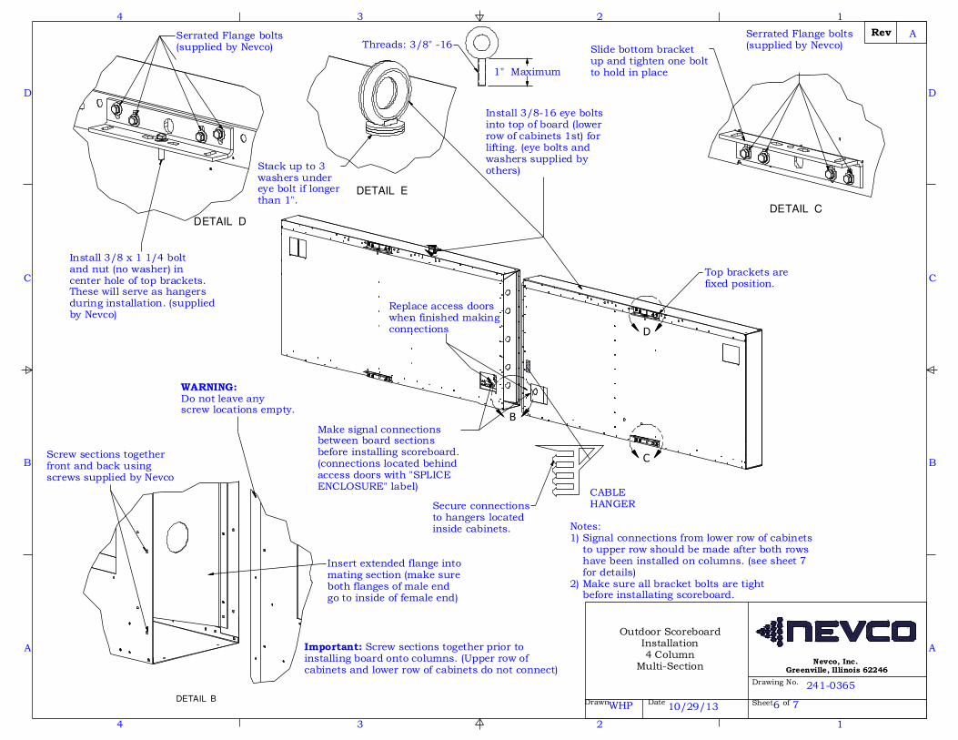
Insert extended flange intomating section (make sureboth flanges of male endgo to inside of female end)
Important: Screw sections together prior toinstalling board onto columns. (Upper row of cabinets and lower row of cabinets do not connect)
Make signal connectionsbetween board sections before installing scoreboard.(connections located behindaccess doors with "SPLICEENCLOSURE" label)
Secure connectionsto hangers located inside cabinets.
Replace access doors when finished making connections
Notes:1) Signal connections from lower row of cabinets to upper row should be made after both rows have been installed on columns. (see sheet 7 for details)2) Make sure all bracket bolts are tight before installating scoreboard.
1" Maximum
Threads: 3/8" -16
WARNING:Do not leave anyscrew locations empty.
Slide bottom bracketup and tighten one boltto hold in place
WHP 10/29/13
Outdoor ScoreboardInstallation4 Column
Multi-Section
241-0365
6 7
Screw sections togetherfront and back usingscrews supplied by Nevco
Install 3/8 x 1 1/4 boltand nut (no washer) incenter hole of top brackets.These will serve as hangersduring installation. (suppliedby Nevco)
Stack up to 3washers undereye bolt if longerthan 1".
Install 3/8-16 eye boltsinto top of board (lowerrow of cabinets 1st) forlifting. (eye bolts andwashers supplied byothers)
Top brackets arefixed position.
Serrated Flange bolts(supplied by Nevco)
Serrated Flange bolts(supplied by Nevco)
A

STEP ONE Install First Row
STEP TWO Install Second Row
Hanging Detail
DETAIL G
DETAIL H
DETAIL J
1
1
2
2
3
3
4
4
A A
B B
C C
D D
Drawn Date
Drawing No.
Sheet of
Rev
Nevco, Inc. Greenville, Illinois 62246
G
H
J
Column
Install top row and tighten allbracket bolts. Secure connections
to hangers located inside cabinets.
CABLE HANGER
Spreader bar preferred forlifting (see installation instructions for more details)
WARNING:Do not lift scoreboards with any other additional weight attached such as laterals or other structural components
Column
ScoreboardTop
ColumnScoreboardBottom
Note: Details below show onlytwo columns for clarity. Actual installation will have 4columns.
WHP 10/29/13
Outdoor ScoreboardInstallation4 Column
Multi-Section
241-0365
7 7
Remove eye boltsfrom first row andinstall on second row
Make power/signal connectionbetween upper and lower rowsof cabinets after board has beeninstalled.- connections located behindaccess doors)- Pull cables from lower sectioninto upper section (connectionsmust be made and permanentlylocated in upper section)
Tighten all bracketbolts on first rowbefore installingsecond row.
Side ViewScoreboard Installation
Bolt brackets together using bolts,nuts, washers and lock washerssupplied by Nevco. (3/8 x 1 3/4 bolts)
2 bolts requiredper bracket set.
Scoreboard
Bolt installed in topbrackets of each rowwill serve as hanger.
A

FRONT VIEW
BOTTOM SCOREBOARDSECTION
TOP SCOREBOARD SECTION
Drawn Date
Drawing No.
Sheet of
Rev
Nevco, Inc. Greenville, Illinois 62246
1
1
2
2
3
3
4
4
A A
B B
C C
D D
12/12/14
241-0360
DBB
Outdoor ScoreboardInstallation
2/3 Column WithLaterals
Steel ColumnA992 50ksi Steel
(see sheets 4-7)
6"From end of columnto edge of concrete
10'(to bottom of lowest displaycomponent)
Pier Depth(see sheets 4-7)
SCOREBOARDHEIGHT
WIDTH
Coarse aggregate concrete(fc = 2500 psi minimum)
Equal Equal
Pier Diameter(see sheets 4-7)
Concrete must slope away from columns
SCOREBOARD DIMENSIONS AND SPECIFICATIONS
MODEL WIDTH HEIGHT WEIGHT WEIGHT Max "A" Min "A"
1604 28' 8' 3/16" 650 712 22' 14'
1606, 3615, 3617,
3618, 3619, 7630
7631, 7632
24' 8' 3/16" 570 632 20' 13'
3685,768524' 8' 3/16" N/A 740 20' 13'
7605, 7615, 762524' 10' 6 9/32" 730 792 20' 13'
8601, 860224' 8' 3/16" 970 1032 20' 13'
3621 20' 8' 3/16" 520 582 18' 12'
3682 20' 8' 3/16" N/A 690 18' 12'
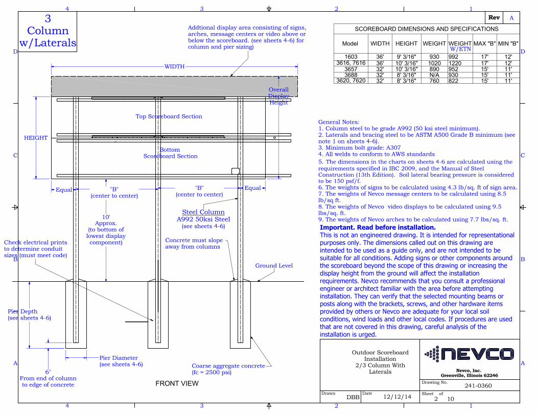
Addtional display area consisting of signs, arches, message centers or video above or below the scoreboard. (see sheets 4-6) for column and pier sizing)
Check electrical printsto determine conduit sizes (must meet code)
OverallDisplayHeight
"A"(center to center)
Important. Read before installation.
This is not an engineered drawing. It is intended for
representational purposes only. The dimensions called out
on this drawing are intended to be used as a guide only, and are not
intended to be suitable for all conditions. Adding signs or other
components around the scoreboard beyond the scope of this drawing or
increasing the display height from the ground will affect the installation
requirements. Nevco recommends that you consult a professional
engineer or architect familiar with the area before attempting installation.
They can verify that the selected mounting beams or posts along with the
brackets, screws, and other hardware items provided by others or Nevco
are adequate for your local soil conditions, wind loads and other local
codes. If procedures are used that are not covered in this drawing,
careful analysis of the installation is urged.
General Notes:1. Column steel to be grade A992 (50 ksi steel minimum).2. Laterals and bracing steel to be ASTM A500 Grade B minimum (see note 1 on sheets 4-6).3. Minimum bolt grade: A3074. All welds to conform to AWS standards5. The dimensions in the charts on sheets 4-6 are calculated using the requirements specified in IBC 2009, and the Manual of Steel Construction (13th Edition). Soil lateral bearing pressure is considered to be 150 psf/f.6. The weights of signs to be calculated using 4.3 lb/sq. ft of sign area. 7. The weights of Nevco message centers to be calculated using 8.5 lb/sq ft.8. The weights of Nevco video displays to be calculated using 9.5 lbs/sq. ft.9. The weights of Nevco arches to be calculated using 7.7 lbs/sq. ft.
2 Column
w/LateralsW/ETN
A
1 10
FRONT VIEW
Drawn Date
Drawing No.
Sheet of
Rev
Nevco, Inc. Greenville, Illinois 62246
1
1
2
2
3
3
4
4
A A
B B
C C
D D
Top Scoreboard Section
Bottom Scoreboard Section
SCOREBOARD DIMENSIONS AND SPECIFICATIONS
Model WIDTH HEIGHT WEIGHT WEIGHT MAX "B" MIN "B"
1603 36' 9' 3/16" 930 992 17' 12'
3616, 761636' 10' 3/16" 1020 1220 17' 12'
3657 32' 10' 3/16" 890 952 15' 11'
3688 32' 8' 3/16" N/A 930 15' 11'
3620, 762032' 8' 3/16" 760 822 15' 11'
Important. Read before installation.
This is not an engineered drawing. It is intended for representational
purposes only. The dimensions called out on this drawing are
intended to be used as a guide only, and are not intended to be
suitable for all conditions. Adding signs or other components around
the scoreboard beyond the scope of this drawing or increasing the
display height from the ground will affect the installation
requirements. Nevco recommends that you consult a professional
engineer or architect familiar with the area before attempting
installation. They can verify that the selected mounting beams or
posts along with the brackets, screws, and other hardware items
provided by others or Nevco are adequate for your local soil
conditions, wind loads and other local codes. If procedures are used
that are not covered in this drawing, careful analysis of the
installation is urged.
WIDTH
HEIGHT
Ground Level
Coarse aggregate concrete(fc = 2500 psi)
Concrete must slope away from columns
Steel ColumnA992 50ksi Steel
(see sheets 4-6)
Check electrical printsto determine conduit sizes (must meet code)
6"From end of columnto edge of concrete
Pier Depth(see sheets 4-6)
Equal "B"(center to center)
"B"(center to center)
Equal
Pier Diameter(see sheets 4-6)
10'Approx.
(to bottom oflowest displaycomponent)
OverallDisplayHeight
241-0360
Outdoor ScoreboardInstallation
2/3 Column WithLaterals
12/12/14DBB
3Column
w/LateralsAddtional display area consisting of signs, arches, message centers or video above or below the scoreboard. (see sheets 4-6) for column and pier sizing)
General Notes:1. Column steel to be grade A992 (50 ksi steel minimum).2. Laterals and bracing steel to be ASTM A500 Grade B minimum (see note 1 on sheets 4-6).3. Minimum bolt grade: A3074. All welds to conform to AWS standards5. The dimensions in the charts on sheets 4-6 are calculated using the requirements specified in IBC 2009, and the Manual of Steel Construction (13th Edition). Soil lateral bearing pressure is considered to be 150 psf/f.6. The weights of signs to be calculated using 4.3 lb/sq. ft of sign area.7. The weights of Nevco message centers to be calculated using 8.5 lb/sq ft.8. The weights of Nevco video displays to be calculated using 9.5 lbs/sq. ft.9. The weights of Nevco arches to be calculated using 7.7 lbs/sq. ft.
W/ETN
A
2 10

1
1
2
2
3
3
4
4
A A
B B
C C
D D
Drawn Date
Drawing No.
Sheet of
Rev
Nevco, Inc. Greenville, Illinois 62246
DBB
Outdoor ScoreboardInstallation
2/3 Column WithLaterals
12/12/14
241-0360
LATERAL REQUIREMENTS
Model
90mph Lateral 130mph Lateral 150mph Lateral # Laterals Req. Lateral Length Bracing Laterals
1603, 3616, 7616TS 3 x 3 x 1/8 TS 3.5 x 3.5 x 3/16 TS 3.5 x 3.5 x 1/4 4 31' 6" TS 4 x 3 x 3/16
3657, 3688TS 2.25 x 2.25 x 1/4 TS 3 x 3 x 3/16 TS 3 x 3 x 1/4 4 25' 6" TS 4 x 3 x 3/16
3620, 7620TS 2.25 x 2.25 x 3/16 TS 3 x 3 x 1/8 TS 3 x 3 x 3/16 4 25' 6" TS 4 x 3 x 3/16
1604 TS 2.5 x 2.5 x 3/16 TS 3 x 3 x 1/8 TS 3 x 3 x 3/16 4 21' 6" TS 4 x 3 x 3/16
7605, 7615, 7625TS 2.5 x 2.5 x 1/4 TS 3.5 x 3.5 x 3/16 TS 3.5 x 3.5 x 1/4 6 17' 6" TS 4 x 3 x 3/16
1606, 3615, 3617
3618, 3619, 3685,
7630, 7631, 7632,
7685, 8601, 8602
TS 2.5 x 2.5 x 3/16 TS 3 x 3 x 3/16 TS 3.5 x 3.5 x 3/16 4 17' 6" TS 4 x 3 x 3/16
3621, 3682TS 2.5 x 2.5 x 3/16 TS 3 x 3 x 3/16 TS 3 x 3 x 3/16 4 19' 6" TS 4 x 3 x 3/16
Notes:1) Lateral material to be ASTM A500 Grade B minimum.2) Quantity of laterals in the chart above includes the quantity required to mount the scoreboard only and does not include bracing laterals. (See detail on sheet 7 to determine required amount of bracing laterals).3) Additional display components such as signs, message centers or video displays will require additional laterals. See separate installation print for details.
A
3 10

1
1
2
2
3
3
4
4
A A
B B
C C
D D
Drawn Date
Drawing No.
Sheet of
Rev
Nevco, Inc. Greenville, Illinois 62246
Outdoor ScoreboardInstallation
2/3 Column WithLaterals
DBB 12/12/14
241-0360
20' W
ide
Inst
alls
(Exp
osur
e C
- 2 C
ol)
20' W
ide
Inst
alls
(Exp
osur
e B
- 2 C
ol)
90 MPH WIND ZONESColumn and Pier Requirements (Based on ASCE 7-05)
Display Height
Pier Dia
Pier Depth Column Length
Column *
8
2' (3') 10' (8'6") 27' (25'6")
W10 x 22
10
2' (3') 11' (9'6") 30' (28'6")
W10 x 26
12
2' (3') 12' (10') 33' (31')
W12 x 26
14
2' (3') 13' (11') 36' (34')
W14 x 30
16
2' (3') 14' (11'6") 39' (36'6")
W14 x 34
18
2' (3') 15'6" (12') 42'6" (39')
W16 x 36
20
2' (3') 17' (13') 46' (42')
W16 x 40
22
2' (3') 19' (14'6") 50' (45'6")
W16 x 50
25
3' (4') 16'6" (13'6") 50'6" (47'6")
W18 x 55
30
3' (4') 19' (16') 58' (55')
W21 x 62
35
3' (4') 21'6" (18') 65'6" (62')
W24 x 68
40
3' (4') 24'6" (20'6") 73'6" (69'6")
W24 x 84
Column and Pier Requirements (Based on ASCE 7-05)
Display Height
Pier Dia
Pier Depth Column Length
Column *
8
2' (3') 8'6" (7'6") 25'6" (24'6")
W8 x18
10
2' (3') 9'6" (8') 28'6" (27')
W8 x 21
12
2' (3') 10'6" (9') 31'6" (30')
W14 x 22
14
2' (3') 11' (9'6") 34' (32'6")
W10 x 26
16
2' (3') 11'6" (10') 36'6" (35')
W12 x 26
18
2' (3') 12'6" (10'6") 39'6" (37'6")
W12 x 30
20
2' (3') 13'6" (11') 42'6" (40')
W14 x 34
22
2' (3') 15' (12') 46' (43')
W16 x 36
25
3' (4') 13' (11'6") 47' (45'6")
W14 x 43
30
3' (4') 15'6" (13') 54'6" (52')
W18 x 50
35
3' (4') 17'6" (15') 61'6" (59')
W21 x 55
40
3' (4') 20' (17') 69' (66')
W21 x 68
130 MPH WIND ZONESColumn and Pier Requirements (Based on ASCE 7-05)
Display Height
Pier Dia
Pier Depth Column Length
Column *
8
2' (3') 14' (11'6") 31' (28'6")
W14 x 30
10
2' (3') 16' (12'6") 35' (31'6")
W18 x 35
12
2' (3') 18'6" (14'6") 39'6" (35'6")
W14 x 43
14
2' (3') 20'6" (16') 43'6" (39')
W16 x 50
16
2' (3') 23' (17'6") 48' (42'6")
W18 x 55
18
2' (3') 25' (19') 52' (46')
W21 x 55
20
2' (3') 27'6" (21') 56'6" (50')
W21 x 62
22
2' (3') 31' (23'6") 62' (54'6")
W24 x 68
25
3' (4') 26' (21'6") 60' (55'6")
W24 x 84
30
3' (4') 30'6" (25') 69'6" (64')
W21 x 101
35
3' (4') 35' (29') 79' (73')
W24 x 117
40
3' (4') 39'6" (32'6") 88'6" (81'6")
W24 x 146
20' W
ide
Inst
alls
(Exp
osur
e B
- 2 C
ol)
20' W
ide
Inst
alls
(Exp
osur
e C
- 2 C
ol) Column and Pier Requirements (Based on ASCE 7-05)
Display Height
Pier Dia
Pier Depth Column Length
Column *
8
2' (3') 11'6" (9'6") 28'6" (26'6")
W10 x 26
10
2' (3') 12'6" (10'6") 31'6" (29'6")
W12 x 30
12
2' (3') 14'6" (11'6") 35'6" (32'6")
W14 x 34
14
2' (3') 16' (12'6") 39' (35'6")
W16 x 36
16
2' (3') 18' (14') 43' (39')
W14 x 43
18
2' (3') 19'6" (15') 46'6" (42')
W16 x 50
20
2' (3') 21'6" (16'6") 50'6" (45'6")
W18 x 50
22
2' (3') 24' (18'6") 55' (49'6")
W21 x 55
25
3' (4') 20'6" (17'6") 54'6" (51'6")
W21 x 68
30
3' (4') 24'6" (20') 63'6" (59')
W24 x 76
35
3' (4') 28' (23'6") 72' (67'6")
W24 x 94
40
3' (4') 31'6" (26'6") 80'6" (75'6")
W24 x 104
Chart Notes:1. * It is required that 4x3x3/16 steel tubing be welded to back of columns 10' from the ground and every 10' to the top of the column for bracing. (See detail on sheet 7)2. Wind loading figured at Exposure "C" - Open terrain with scattered obstructions having heights generally less than 30 feet. This category includes flat open country, grasslands, and all water surfaces in hurricane prone areas.3. Wind loading figured at Exposure "B" - Urban and suburban areas, wooded areas, or other terrain with numerous closely spaced obstructions having the size of single-family dwellings or larger. These areas prevail in the upwind direction for a distance of 2600 feet or 20 times the structure height, whichever is greater.
150 MPH WIND ZONESColumn and Pier Requirements (Based on ASCE 7-05)
Column *
Column LengthPier Depth
Pier Dia
Display Height
W16 x 36
33'6" (30')16'6" (13')2' (3')
8
W21 x 44
38'6" (34')19'6" (15')2' (3')
10
W18 x 50
43'6" (38')22'6" (17')2' (3')
12
W21 x 55
48' (42')25' (19')2' (3')
14
W21 x 62
53' (46')28' (21')2' (3')
16
W21 x 68
57'6" (50')30'6" (23')2' (3')
18
W24 x 76
62'6" (54')33'6" (25')2' (3')
20
W24 x 84
68'6" (59'6")37'6" (28'6")2' (3')
22
W21 x 101
65'6" (60')31'6" (26')3' (4')
25
W24 x 131
76' (69'6")37' (30'6")3' (4')
30
W24 x 162
86'6" (79')42'6" (35')3' (4')
35
W24 x 192
97'6" (88'6")48'6" (39'6")3' (4')
40
20' W
ide
Inst
alls
(Exp
osur
e C
- 2 C
ol)
20' W
ide
Inst
alls
(Exp
osur
e B
- 2 C
ol) Column and Pier Requirements (Based on ASCE 7-05)
Display Height
Pier Dia
Pier Depth Column Length
Column *
8
2' (3') 13' (11') 30' (28')
W12 x 30
10
2' (3') 15' (12') 34' (31')
W14 x 34
12
2' (3') 17'6" (13'6") 38'6" (34'6")
W16 x 40
14
2' (3') 19'6" (15') 42'6" (38')
W21 x 44
16
2' (3') 21'6" (16'6") 46'6" (41'6")
W18 x 50
18
2' (3') 23'6" (18') 50'6" (45')
W21 x 55
20
2' (3') 26' (20') 55' (49')
W21 x 62
22
2' (3') 29'6" (22'6") 60'6" (53'6")
W21 x 68
25
3' (4') 25' (20'6") 59' (54'6")
W24 x 76
30
3' (4') 29'6" (24'6") 68'6" (63'6")
W24 x 94
35
3' (4') 34' (28') 78' (72')
W24 x 117
40
3' (4') 38'6" (31'6") 87'6" (80'6")
W24 x 146
A
4 10

1
1
2
2
3
3
4
4
A A
B B
C C
D D
Drawn Date
Drawing No.
Sheet of
Rev
Nevco, Inc. Greenville, Illinois 62246
Column and Pier Requirements (Based on ASCE 7-05)
Display Height
Pier Dia
Pier Depth Col Length
Column *
8
2' (3') 9'6" (7'6") 27'6" (25'6")
W14 x 22
10
2' (3') 11' (9') 31' (29')
W12 x 26
12
2' (3') 13' (10') 35' (32')
W12 x 30
14
2' (3') 14'6" (11'6") 38'6" (35'6")
W14 x 34
16
2' (3') 16' (12'6") 42' (38'6")
W16 x 36
18
2' (3') 17'6" (13'6") 45'6" (41'6")
W14 x 43
20
2' (3') 19' (14'6") 49' (44'6")
W14 x 48
22
2' (3') 20'6" (16') 52'6" (48')
W18 x 50
25
3' (4') 18'6" (15'6") 53'6" (50'6")
W21 x 55
30
3' (4') 21'6" (18') 61'6" (58')
W24 x 68
35
3' (4') 24'6" (20'6") 69'6" (65'6")
W24 x 84
40
3' (4') 27'6" (23') 77'6" (73')
W24 x 94
Column and Pier Requirements (Based on ASCE 7-05 Exposure B for 90mph Wind)
Display Height
Pier Dia.
Pier Depth Col. Length
Column *
8
2' (3') 7'6" (6') 25'6" (24')
W8 x 21
10
2' (3') 9' (7') 29' (27')
W10 x 22
12
2' (3') 10' (8') 32' (30')
W10 x 26
14
2' (3') 11'6" (9') 35'6" (33')
W12 x 26
16
2' (3') 12'6" (10') 38'6" (36')
W14 x 30
18
2' (3') 14' (11') 42' (39')
W14 x 34
20
2' (3') 15' (12') 45' (42')
W16 x 36
22
2' (3') 16'6" (12'6") 48'6" (44'6")
W16 x 40
25
3' (4') 14'6" (12'6") 49'6" (47'6")
W16 x 50
30
3' (4') 17' (14'6") 57' (54'6")
W21 x 55
35
3' (4') 20' (16'6") 65' (61'6")
W21 x 68
40
3' (4') 22'6" (18'6") 72'6" (68'6")
W24 x 76
Column and Pier Requirements (Based on ASCE 7-05)
Display Height
Pier Dia.
Pier Depth Col. Length
Column*
8
2' (3') 11' (9'6") 29' (27'6")
W10 x 26
10
2' (3') 12'6" (10'6") 32'6" (30'6")
W12 x 30
12
2' (3') 14' (11'6") 36' (33'6")
W14 x 34
14
2' (3') 15'6" (12') 39'6" (36')
W16 x 36
16
2' (3') 17'6" (13'6") 43'6" (39'6")
W16 x 40
18
2' (3') 19'6" (15') 47'6" (43')
W14 x 48
20
2' (3') 21' (16') 51' (46')
W18 x 50
22
2' (3') 22'6" (17'6") 54'6" (49'6")
W18 x 55
25
3' (4') 19'6" (16') 54'6" (51')
W21 x 62
30
3' (4') 23'6" (19'6") 63'6" (59'6")
W24 x 76
35
3' (4') 27' (22'6") 72' (67'6")
W24 x 94
40
3' (4') 30'6" (25'6") 80'6" (75'6")
W24 x 104
Column and Pier Requirements (Based on ASCE 7-05 Exposure B for 90mph Wind L
Display Height
Pier Dia.
Pier Depth Col. Length
Column *
8
2' (3') 9'6" (8'6") 27'6" (26'6")
W10 x 22
10
2' (3') 10'6" (9') 30'6" (29')
W10 x 26
12
2' (3') 11'6" (10') 33'6" (32')
W12 x 26
14
2' (3') 12'6" (10'6") 36'6" (34'6")
W12 x 30
16
2' (3') 14' (11'6") 40' (37'6")
W14 x 34
18
2' (3') 15'6" (12') 43'6" (40')
W16 x 36
20
2' (3') 16'6" (13') 46'6" (43')
W16 x 40
22
2' (3') 18' (14') 50' (46')
W21 x 44
25
3' (4') 15'6" (13') 50'6" (48')
W18 x 50
30
3' (4') 19' (16') 59' (56')
W21 x 62
35
3' (4') 22' (18') 67' (63')
W24 x 68
40
3' (4') 24'6" (20'6") 74'6" (70'6")
W24 x 84
90 MPH WIND ZONES24
' Wid
e In
stal
ls(E
xpos
ure
C - 2
Col
)
241-0360
Outdoor ScoreboardInstallation
2/3 Column WithLaterals
12/12/14DBB
28' W
ide
Inst
alls
(Exp
osur
e C
- 2 C
ol)
Column and Pier Requirements (Based on ASCE 7-05)
Display Height
Pier Dia.
Pier Depth Col. Length
Column*
8
2' (3') 10' (8'6") 28' (26'6")
W10 x 22
10
2' (3') 11' (9'6") 31' (29'6")
W10 x 26
12
2' (3') 11'6" (10') 33'6" (32')
W12 x 26
14
2' (3') 12'6" (11') 36'6" (35')
W12 x 30
16
2' (3') 14' (11'6") 40' (37'6")
W14 x 34
18
2' (3') 15'6" (12') 43'6" (40')
W16 x 36
20
2' (3') 17' (13') 47' (43')
W16 x 40
22
3' (4') 14' (12') 46' (44')
W21 x 44
25
3' (4') 15'6" (13') 50'6" (48')
W18 x 50
30
3' (4') 18' (15'6") 58' (55'6")
W21 x 62
35
3' (4') 21'6" (18') 66'6" (63')
W24 x 68
40
3' (4') 24'6" (20'6") 74'6" (70'6")
W24 x 84
32' W
ide
Inst
alls
(Exp
osur
e C
- 3 C
ol)
Column and Pier Requirements (Based on ASCE 7-05 Exposure B 90mph Wind)
Display Height
Pier Dia.
Pier Depth Col. Length
Column*
8
2' (3') 8'6" (7'6") 26'6" (25'6")
W8 x 18
10
2' (3') 9'6" (8') 29'6" (28')
W8 x 21
12
2' (3') 10' (8'6") 32' (30'6")
W10 x 22
14
2' (3') 11' (9'6") 35' (33'6")
W10 x 26
16
2' (3') 11'6" (10') 37'6" (36')
W12 x 26
18
2' (3') 12'6" (10'6") 40'6" (38'6")
W12 x 30
20
2' (3') 13'6" (11') 43'6" (41')
W14 x 34
22
3' (4') 11'6" (10'6") 43'6" (42'6")
W18 x 35
25
3' (4') 12'6" (11'6") 47'6" (46'6")
W16 x 40
30
3' (4') 14'6" (12'6") 54'6" (52'6")
W16 x 50
35
3' (4') 17'6" (15') 62'6" (60')
W21 x 55
40
3' (4') 20' (16'6") 70' (66'6")
W21 x 68
Chart Notes:1. * It is required that 4x3x3/16 steel tubing be welded to back of columns 10' from the ground and every 10' to the top of the column for bracing. (See detail on sheet 7)2. Wind loading figured at Exposure "C" - Open terrain with scattered obstructions having heights generally less than 30 feet. This category includes flat open country, grasslands, and all water surfaces in hurricane prone areas.3. Wind loading figured at Exposure "B" - Urban and suburban areas, wooded areas, or other terrain with numerous closely spaced obstructions having the size of single-family dwellings or larger. These areas prevail in the upwind direction for a distance of 2600 feet or 20 times the structure height, whichever is greater.
Column and Pier Requirements(Based on ASCE 7-05)
Display Height
Pier Dia
Pier Depth Col. Length
Column*
9
2' (3') 11' (9'6") 30' (28'6")
W10 x 26
10
2' (3') 11'6" (10') 31'6" (30')
W12 x 26
11
2' (3') 12' (10'6") 33' (31'6")
W12 x 26
12
2' (3') 12'6" (10'6") 34'6" (32'6")
W12 x 30
13
2' (3') 13'6" (11') 36'6" (34')
W14 x 30
14
2' (3') 14' (11'6") 38' (35'6")
W14 x 34
15
2' (3') 15' (12') 40' (37')
W18 x 35
20
3' (4') 14'6" (12'6") 44'6" (42'6")
W14 x 48
25
3' (4') 17'6" (14'6") 52'6" (49'6")
W21 x 55
30
3' (4') 20'6" (17') 60'6" (57')
W21 x 68
35
3' (4') 23' (19'6") 68' (64'6")
W24 x 76
40
3' (4') 27'6" (23') 77'6" (73')
W24 x 94
36' W
ide
Inst
alls
(Exp
osur
e C
- 3 C
ol)
24' W
ide
Inst
alls
(Exp
osur
e B
- 2 C
ol)
28' W
ide
Inst
alls
(Exp
osur
e B
- 2 C
ol)
32' W
ide
Inst
alls
(Exp
osur
e B
- 3 C
ol)
36' W
ide
Inst
alls
(Exp
osur
e B
- 3 C
ol) Column and Pier Requirements (Based on ASCE 7-05)
Display Height
Pier Dia.
Pier Depth Col. Length
Column*
2' (3') 9'6" (8') 9'6" (8') 28'6" (27')
W8 x 21
2' (3') 10' (8'6") 10' (8'6") 30' (28'6")
W10 x 22
2' (3') 10'6" (9') 10'6" (9') 31'6" (30')
W14 x 22
2' (3') 11' (9'6") 11' (9'6") 33' (31'6")
W10 x 26
2' (3') 11' (9'6") 11' (9'6") 34' (32'6")
W12 x 26
2' (3') 11'6" (10') 11'6" (10') 35'6" (34')
W12 x 26
2' (3') 12' (10'6") 12' (10'6") 37' (35'6")
W12 x 30
3' (4') 12' (10'6") 12' (10'6") 42' (40'6")
W16 x 36
3' (4') 14' (12') 14' (12') 49' (47')
W21 x 44
3' (4') 16'6" (14') 16'6" (14') 56'6" (54')
W18 x 55
3' (4') 19' (16') 19' (16') 64' (61')
W21 x 62
3' (4') 22' (18'6") 22' (18'6") 72' (68'6")
W24 x 76
A
5 10

1
1
2
2
3
3
4
4
A A
B B
C C
D D
Drawn Date
Drawing No.
Sheet of
Rev
Nevco, Inc. Greenville, Illinois 62246
Column and Pier Requirements (Based on ASCE 7-05)
Display Height
Pier Dia
Pier Depth Col Length
Column *
8
2' (3') 15'6" (12') 33'6" (30')
W14 x 34
10
2' (3') 18' (14') 38' (34')
W16 x 40
12
2' (3') 20'6" (15'6") 42'6" (37'6")
W16 x 50
14
3' (4') 18' (15') 42' (39')
W18 x 55
16
3' (4') 20' (16'6") 46' (42'6")
W21 x 55
18
3' (4') 21'6" (18') 49'6" (46')
W21 x 68
20
3' (4') 23'6" (19'6") 53'6" (49'6")
W24 x 68
22
3' (4') 25'6" (21') 57'6" (53')
W24 x 76
25
3' (4') 29'6" (24'6") 64'6" (59'6")
W24 x 94
30
3' (4') 34'6" (28'6") 74'6" (68'6")
W24 x 117
35
3' (4') 40' (32'6") 85' (77'6")
W24 x 146
40
3' (4') 45' (37') 95' (87')
W24 x 176
Column and Pier Requirements (Based on ASCE 7-05)
Display Height
Pier Dia.
Pier Depth Col. Length
Column *
8
2' (3') 12' (10'6") 30' (28'6")
W12 x 26
10
2' (3') 14' (11'6") 34' (31'6")
W14 x 34
12
2' (3') 16' (12'6") 38' (34'6")
W16 x 36
14
3' (4') 14' (12') 38' (36')
W14 x 43
16
3' (4') 15'6" (13') 41'6" (39')
W16 x 50
18
3' (4') 17' (14') 45' (42')
W18 x 55
20
3' (4') 18'6" (15'6") 48'6" (45'6")
W21 x 55
22
3' (4') 20' (16'6") 52' (48'6")
W21 x 62
25
3' (4') 23'6" (19'6") 58'6" (54'6")
W24 x 68
30
3' (4') 27'6" (22'6") 67'6" (62'6")
W24 x 94
35
3' (4') 31'6" (26') 76'6" (71')
W24 x 104
40
3' (4') 36' (29'6") 86' (79'6")
W24 x 131
Column and Pier Requirements (Based on ASCE 7-05)
Display Height
Pier Dia.
Pier Depth Col. Length
Column*
8
2' (3') 17' (13') 35' (31')
W16 x 36
10
2' (3') 20' (15') 40' (35')
W21 x 44
12
2' (3') 22'6" (17'6") 44'6" (39'6")
W18 x 50
14
3' (4') 19'6" (16') 43'6" (40')
W21 x 55
16
3' (4') 22' (18') 48' (44')
W21 x 68
18
3' (4') 24' (20') 52' (48')
W24 x 68
20
3' (4') 26' (21'6") 56' (51'6")
W24 x 76
22
3' (4') 28'6" (23'6") 60'6" (55'6")
W24 x 84
25
3' (4') 31'6" (26') 66'6" (61')
W21 x 101
30
3' (4') 38'6" (31'6") 78'6" (71'6")
W24 x 131
35
3' (4') 44'6" (36'6") 89'6" (81'6")
W24 x 162
40
3' (4') 50' (41') 100' (91')
W24 x 192
Column and Pier Requirements (Based on ASCE 7-05)
Display Height
Pier Dia.
Pier Depth Col. Length
Column *
8
2' (3') 13' (11') 31' (29')
W12 x 30
10
2' (3') 15'6" (12') 35'6" (32')
W14 x 34
12
2' (3') 17'6" (13'6") 39'6" (35'6")
W16 x 40
14
3' (4') 15' (12'6") 39' (36'6")
W14 x 48
16
3' (4') 17' (14'6") 43' (40'6")
W18 x 55
18
3' (4') 19' (15'6") 47' (43'6")
W21 x 55
20
3' (4') 20'6" (17') 50'6" (47')
W21 x 62
22
3' (4') 22' (18'6") 54' (50'6")
W21 x 68
25
3' (4') 25' (20'6") 60' (55'6")
W24 x 76
30
3' (4') 30'6" (25') 70'6" (65')
W21 x 101
35
3' (4') 35' (29') 80' (74')
W24 x 117
40
3' (4') 40' (33') 90' (83')
W24 x 146
130 MPH WIND ZONES24
' Wid
e In
stal
ls(E
xpos
ure
C - 2
Col
)
241-0360
Outdoor ScoreboardInstallation
2/3 Column WithLaterals
12/12/14 6 10 DBB
28' W
ide
Inst
alls
(Exp
osur
e C
- 2 C
ol)
Column and Pier Requirements (Based on ASCE 7-05)
Display Height
Pier Dia.Pier Depth Col. Length
Column*
8
2' (3') 13'6" (11') 31'6" (29')
W14 x 30
10
2' (3') 16' (12') 36' (32')
W18 x 35
12
2' (3') 18' (14') 40' (36')
W16 x 40
14
3' (4') 15'6" (13') 39'6" (37')
W16 x 50
16
3' (4') 17' (14'6") 43' (40'6")
W18 x 55
18
3' (4') 19' (16') 47' (44')
W21 x 55
20
3' (4') 21' (17'6") 51' (47'6")
W21 x 62
22
3' (4') 22'6" (18'6") 54'6" (50'6")
W24 x 68
25
3' (4') 25' (20'6") 60' (55'6")
W24 x 76
30
3' (4') 29' (24') 69' (64')
W24 x 94
35
3' (4') 35' (29') 80' (74')
W24 x 117
40
3' (4') 39'6" (32'6") 89'6" (82'6")
W24 x 146
32' W
ide
Inst
alls
(Exp
osur
e C
- 3 C
ol)
Column and Pier Requirements (Based on ASCE 7-05 Exposure B 90mph Wind)
Display Height
Pier Dia.
Pier Depth Col. Length
Column*
8
2' (3') 11'6" (9'6") 29'6" (27'6")
W10 x 26
10
2' (3') 12'6" (10'6") 32'6" (30'6")
W12 x 30
12
2' (3') 14' (11'6") 36' (33'6")
W14 x 34
14
3' (4') 12'6" (11') 36'6" (35')
W16 x 36
16
3' (4') 13'6" (12') 39'6" (38')
W16 x 40
18
3' (4') 15' (12'6") 43' (40'6")
W16 x 50
20
3' (4') 16'6" (14') 46'6" (44')
W18 x 50
22
3' (4') 18' (15') 50' (47')
W21 x 55
25
3' (4') 20' (16'6") 55' (51'6")
W21 x 62
30
3' (4') 23' (19'6") 63' (59'6")
W24 x 76
35
3' (4') 28' (23') 73' (68')
W24 x 94
40
3' (4') 31'6" (26') 81'6" (76')
W24 x 104
Chart Notes:1. * It is required that 4x3x3/16 steel tubing be welded to back of columns 10' from the ground and every 10' to the top of the column for bracing. (See detail on sheet 7)2. Wind loading figured at Exposure "C" - Open terrain with scattered obstructions having heights generally less than 30 feet. This category includes flat open country, grasslands, and all water surfaces in hurricane prone areas.3. Wind loading figured at Exposure "B" - Urban and suburban areas, wooded areas, or other terrain with numerous closely spaced obstructions having the size of single-family dwellings or larger. These areas prevail in the upwind direction for a distance of 2600 feet or 20 times the structure height, whichever is greater.
Column and Pier Requirements(Based on ASCE 7-05)
Display Height
Pier Dia
Pier Depth Col. Length
Column*
9
2' (3') 16'6" (12'6") 35'6" (31'6")
W16 x 36
10
2' (3') 17'6" (13'6") 37'6" (33'6")
W16 x 40
11
2' (3') 19' (14'6") 40' (35'6")
W14 x 43
12
3' (4') 15'6" (13') 37'6" (35')
W21 x 44
13
3' (4') 16'6" (13'6") 39'6" (36'6")
W16 x 50
14
3' (4') 17'6" (14'6") 41'6" (38'6")
W18 x 55
15
3' (4') 18'6" (15') 43'6" (40')
W18 x 55
20
3' (4') 23'6" (19'6") 53'6" (49'6")
W24 x 68
25
3' (4') 28' (23') 63' (58')
W24 x 94
30
3' (4') 33' (27') 73' (67')
W24 x 104
35
3' (4') 37'6" (31') 82'6" (76')
W24 x 131
40
3' (4') 44'6" (36'6") 94'6" (86'6")
W24 x 176
36' W
ide
Inst
alls
(Exp
osur
e C
- 3 C
ol)
24' W
ide
Inst
alls
(Exp
osur
e B
- 2 C
ol)
28' W
ide
Inst
alls
(Exp
osur
e B
- 2 C
ol)
32' W
ide
Inst
alls
(Exp
osur
e B
- 3 C
ol)
36' W
ide
Inst
alls
(Exp
osur
e B
- 3 C
ol) Column and Pier Requirements (Based on ASCE 7-05)
Display Height
Pier Dia.Pier Depth Col. Length
Column*
9
2' (3') 13' (11') 32' (30')
W12 x 30
10
2' (3') 13'6" (11'6") 33'6" (31'6")
W14 x 30
11
2' (3') 15' (12') 36' (33')
W14 x 34
12
3' (4') 12' (11') 34' (33')
W16 x 36
13
3' (4') 13' (11'6") 36' (34'6")
W16 x 40
14
3' (4') 13'6" (12') 37'6" (36')
W16 x 40
15
3' (4') 14'6" (12') 39'6" (37')
W21 x 44
20
3' (4') 18'6" (15'6") 48'6" (45'6")
W21 x 55
25
3' (4') 22' (18'6") 57' (53'6")
W24 x 68
30
3' (4') 26' (21'6") 66' (61'6")
W24 x 84
35
3' (4') 30' (25') 75' (70')
W21 x 101
40
3' (4') 35'6" (29'6") 85'6" (79'6")
W24 x 131
A

1
1
2
2
3
3
4
4
A A
B B
C C
D D
Drawn Date
Drawing No.
Sheet of
Rev
Nevco, Inc. Greenville, Illinois 62246
Column and Pier Requirements (Based on ASCE 7-05)
Display Height
Pier Dia
Pier Depth Col Length
Column *
8
2' (3') 18'6" (14') 36'6" (32')
W16 x 40
10
2' (3') 22' (16'6") 42' (36'6")
W16 x 50
12
2' (3') 25' (19') 47' (41')
W18 x 55
14
2' (3') 28'6" (21'6") 52'6" (45'6")
W21 x 62
16
2' (3') 32' (24') 58' (50')
W24 x 68
18
2' (3') 35' (26') 63' (54')
W24 x 76
20
2' (3') 38' (28'6") 68' (58'6")
W24 x 84
22
3' (4') 31' (25'6") 63' (57'6")
W24 x 94
25
3' (4') 36' (29'6") 71' (64'6")
W24 x 117
30
3' (4') 42'6" (34'6") 82'6" (74'6")
W24 x 146
35
3' (4') 48'6" (40') 93'6" (85')
W24 x 176
40
3' (4') 55' (45') 105' (95')
W18 x 283
Column and Pier Requirements (Based on ASCE 7-05)
Display Height
Pier Dia.
Pier Depth Col. Length
Column *
8
2' (3') 14'6" (11'6") 32'6" (29'6")
W14 x 34
10
2' (3') 17' (13') 37' (33')
W16 x 36
12
2' (3') 19'6" (15') 41'6" (37')
W21 x 44
14
2' (3') 22' (17') 46' (41')
W18 x 50
16
2' (3') 24'6" (18'6") 50'6" (44'6")
W21 x 55
18
2' (3') 27' (20'6") 55' (48'6")
W21 x 62
20
2' (3') 29'6" (22'6") 59'6" (52'6")
W21 x 68
22
3' (4') 24' (20') 56' (52')
W18 x 76
25
3' (4') 28' (23'6") 63' (58'6")
W24 x 94
30
3' (4') 33' (27'6") 73' (67'6")
W24 x 104
35
3' (4') 38'6" (31'6") 83'6" (76'6")
W24 x 131
40
3' (4') 43'6" (36') 93'6" (86')
W24 x 162
Column and Pier Requirements (Based on ASCE 7-05)
Display Height
Pier Dia.
Pier Depth Col. Length
Column*
8
2' (3') 20'6" (15'6") 38'6" (33'6")
W21 x 44
10
2' (3') 24' (18'6") 44' (38'6")
W18 x 55
12
2' (3') 28' (21') 50' (43')
W21 x 62
14
2' (3') 31'6" (23'6") 55'6" (47'6")
W21 x 68
16
2' (3') 35'6" (26'6") 61'6" (52'6")
W24 x 76
18
2' (3') 39' (29') 67' (57')
W24 x 84
20
2' (3') 42'6" (32') 72'6" (62')
W24 x 94
22
3' (4') 34'6" (28') 66'6" (60')
W24 x 104
25
3' (4') 38'6" (31'6") 73'6" (66'6")
W24 x 117
30
3' (4') 47'6" (38'6") 87'6" (78'6")
W24 x 162
35
3' (4') 54'6" (44'6") 99'6" (89'6")
W24 x 207
40
3' (4') 62' (50') 112' (100')
W18 x 311
Column and Pier Requirements (Based on ASCE 7-05)
Display Height
Pier Dia.
Pier Depth Col. Length
Column *
8
2' (3') 13' (11') 31' (29')
W12 x 30
10
2' (3') 15'6" (12') 35'6" (32')
W14 x 34
12
2' (3') 17'6" (13'6") 39'6" (35'6")
W16 x 40
14
3' (4') 15' (12'6") 39' (36'6")
W14 x 48
16
3' (4') 17' (14'6") 43' (40'6")
W18 x 55
18
3' (4') 19' (15'6") 47' (43'6")
W21 x 55
20
3' (4') 20'6" (17') 50'6" (47')
W21 x 62
22
3' (4') 22' (18'6") 54' (50'6")
W21 x 68
25
3' (4') 25' (20'6") 60' (55'6")
W24 x 76
30
3' (4') 30'6" (25') 70'6" (65')
W21 x 101
35
3' (4') 35' (29') 80' (74')
W24 x 117
40
3' (4') 40' (33') 90' (83')
W24 x 146
150 MPH WIND ZONES24
' Wid
e In
stal
ls(E
xpos
ure
C - 2
Col
)
241-0360
Outdoor ScoreboardInstallation
2/3 Column WithLaterals
12/12/14 7 10 DBB
28' W
ide
Inst
alls
(Exp
osur
e C
- 2 C
ol)
Column and Pier Requirements (Based on ASCE 7-05)
Display Height
Pier Dia.Pier Depth Col. Length
Column*
8
2' (3') 16'6" (12'6") 34'6" (30'6")
W16 x 36
10
2' (3') 19' (14'6") 39' (34'6")
W14 x 43
12
2' (3') 22' (16'6") 44' (38'6")
W18 x 50
14
2' (3') 24'6" (19') 48'6" (43')
W21 x 55
16
3' (4') 21' (17') 47' (43')
W21 x 62
18
3' (4') 23' (19') 51' (47')
W24 x 68
20
3' (4') 25' (21') 55' (51')
W24 x 76
22
3' (4') 27' (22'6") 59' (54'6")
W24 x 84
25
3' (4') 30'6" (25') 65'6" (60')
W24 x 94
30
3' (4') 35'6" (29') 75'6" (69')
W24 x 117
35
3' (4') 42'6" (35') 87'6" (80')
W24 x 162
40
3' (4') 48' (39'6") 98' (89'6")
W24 x 192
32' W
ide
Inst
alls
(Exp
osur
e C
- 3 C
ol)
Column and Pier Requirements (Based on ASCE 7-05 Exposure B 90mph Wind)
Display Height
Pier Dia.
Pier Depth Col. Length
Column*
8
2' (3') 13' (11') 31' (29')
W12 x 30
10
2' (3') 15' (12') 35' (32')
W14 x 34
12
2' (3') 17' (13') 39' (35')
W16 x 40
14
2' (3') 19' (14'6") 43' (38'6")
W21 x 44
16
3' (4') 16'6" (13'6") 42'6" (39'6")
W18 x 50
18
3' (4') 18' (15') 46' (43')
W21 x 55
20
3' (4') 20' (16'6") 50' (46'6")
W21 x 62
22
3' (4') 21'6" (18') 53'6" (50')
W21 x 68
25
3' (4') 24' (20') 59' (55')
W24 x 76
30
3' (4') 28' (23') 68' (63')
W24 x 94
35
3' (4') 34' (28') 79' (73')
W24 x 117
40
3' (4') 38'6" (31'6") 88'6" (81'6")
W24 x 146
Chart Notes:1. * It is required that 4x3x3/16 steel tubing be welded to back of columns 10' from the ground and every 10' to the top of the column for bracing. (See detail on sheet 7)2. Wind loading figured at Exposure "C" - Open terrain with scattered obstructions having heights generally less than 30 feet. This category includes flat open country, grasslands, and all water surfaces in hurricane prone areas.3. Wind loading figured at Exposure "B" - Urban and suburban areas, wooded areas, or other terrain with numerous closely spaced obstructions having the size of single-family dwellings or larger. These areas prevail in the upwind direction for a distance of 2600 feet or 20 times the structure height, whichever is greater.
Column and Pier Requirements(Based on ASCE 7-05)
Display Height
Pier Dia
Pier Depth Col. Length
Column*
9
2' (3') 20' (15') 39' (34')
W21 x 44
10
2' (3') 21'6" (16'6") 41'6" (36'6")
W16 x 50
11
2' (3') 23' (17'6") 44' (38'6")
W18 x 50
12
2' (3') 24'6" (18'6") 46'6" (40'6")
W18 x 55
13
3' (4') 20' (16'6") 43' (39'6")
W21 x 55
14
3' (4') 21' (17'6") 45' (41'6")
W21 x 62
15
3' (4') 22' (18'6") 47' (43'6")
W21 x 62
20
3' (4') 28'6" (23'6") 58'6" (53'6")
W24 x 84
25
3' (4') 34' (28') 69' (63')
W24 x 104
30
3' (4') 40' (32'6") 80' (72'6")
W24 x 131
35
3' (4') 46' (37'6") 91' (82'6")
W24 x 162
40
3' (4') 54'6" (44'6") 104'6" (94'6")
W18 x 283
36' W
ide
Inst
alls
(Exp
osur
e C
- 3 C
ol)
24' W
ide
Inst
alls
(Exp
osur
e B
- 2 C
ol)
28' W
ide
Inst
alls
(Exp
osur
e B
- 2 C
ol)
32' W
ide
Inst
alls
(Exp
osur
e B
- 3 C
ol)
36' W
ide
Inst
alls
(Exp
osur
e B
- 3 C
ol) Column and Pier Requirements (Based on ASCE 7-05)
Display Height
Pier Dia.Pier Depth Col. Length
Column*
9
2' (3') 15'6" (12') 34'6" (31')
W14 x 34
10
2' (3') 16'6" (12'6") 36'6" (32'6")
W16 x 36
11
2' (3') 18' (13'6") 39' (34'6")
W16 x 40
12
2' (3') 19' (14'6") 41' (36'6")
W21 x 44
13
3' (4') 15'6" (13') 38'6" (36')
W14 x 48
14
3' (4') 16'6" (13'6") 40'6" (37'6")
W18 x 50
15
3' (4') 17'6" (14'6") 42'6" (39'6")
W18 x 55
20
3' (4') 22' (18'6") 52' (48'6")
W21 x 68
25
3' (4') 27' (22') 62' (57')
W24 x 84
30
3' (4') 31'6" (26') 71'6" (66')
W24 x 103
35
3' (4') 36' (30') 81' (75')
W24 x 131
40
3' (4') 43' (35'6") 93' (85'6")
W24 x 162
A

FRONT VIEW
REAR VIEW
DETAIL A
1
1
2
2
3
3
4
4
A A
B B
C C
D D
Drawn Date
Drawing No.
Sheet of
Rev
Nevco, Inc. Greenville, Illinois 62246
Lateral and Hardware Requirements for 2 row Boards(hardware supplied by others)
Model # Dim "B" Dim "C" Dim "D" Lateral Width 3/8 Washers 3/8 Lock Washers 3/8 Nuts
3616, 761655 3/4" 60 1/8" 115 7/8" 31' 6" 64 32 32
1603 43 3/4" 48 1/8" 103 7/8" 31' 6" 64 32 32
3657 55 3/4" 60 1/8" 115 7/8" 25' 6" 64 32 32
3620, 7620, 368843 3/4" 48 1/8" 91 7/8" 25' 6" 64 32 32
1604 43 3/4"' 48 1/8" 91 7/8" 21' 6" 48 24 24
1606, 3615, 3617
3618, 3619,
3685, 7630,
7631, 7632, 7685
43 3/4"' 48 1/8" 91 7/8" 17' 6" 48 24 24
8601, 860243 3/4" 48 1/8" 91 7/8" 17' 6" 48 24 24
General Notes:1) See sheet 3 for lateral size requirements.2) Center and weld Laterals to front face of columns (weld around full perimeter of contact surface with 3/16 fillet.3) Dimensions above should be taken from the top of the SHORTEST column, marked and leveled across to other column.4) Mounting Brackets shipped in separate container.
Required Hand Tools:1. Drill with phillips driver.2. 9/16" wrench3. Ratchet wrench and 9/16" socket4. Level5. Tape measure
Hardware Notes: 1) Minimum bolt grade: A307.2) Hardware above is not required if welding brackets to laterals.3) Consider lateral size when choosing bolt length.
241-0360
Outdoor ScoreboardInstallation
2/3 Column WithLaterals
12/12/14DBB
214" (All Models)
"B"
"C"
"D"
ScoreboardUpper Section
ScoreboardLower Section
Dimension is tobottom of nextlateral.
Dimension is to top of next lateral
Dimension is tobottom of nextlateral.
Dimensions must be increased by an amount equal to the additional column length when installation consists of additionaldisplay components above the scoreboard. If additional columnlength is used to extend above the display, add the additional length to the top dimension below. Dimensions should bemeasured from the top of the shortest column.
Additionaldisplay
component
Top of scoreboard(shown flush with
top of column)
Laterals
Laterals
Additional components fromNevco may be installed onlaterals also. See separateinstallation print.
Equal Equal
If 10' or less, no brace is required at top of column
10'Max
Ground Level
10' Max
Bracing:Laterals must be welded to back of columns 10' apart from the ground up as shown for bracing. 10' spacing must be maintained.Laterals must extend to outer edge of both columns.
Lateral Width
Column
Column
TS 4x3x3/16
Frontof
ColumnMin
Max
IMPORTANT:Weld short side of laterals to column face.(includes bracing laterals)
Note: Bottom section shown for boards with three (3) rows
Lateral and Hardware Requirements for 3 row Boards(hardware supplied by others)
Model Number Dim "B" C D E F Lateral Width 3/8 Washers 3/8 Lock 3/8 Nuts
7605,7615, 7625
25 7/8 30 1/16 73 15/16 78 3/16 122 17'6" 72 36 36
"E" "F"
A
8 10

DETAIL B
DETAIL C
DETAIL D
DETAIL E
B
C
D
E
CABLE HANGER
1
1
2
2
3
3
4
4
A A
B B
C C
D D
Drawn Date
Drawing No.
Sheet of
Rev
Nevco, Inc. Greenville, Illinois 62246
Insert extended flange intomating section (make sureboth flanges of male endgo to inside of female end)
Important: Screw sections together prior toinstalling board onto columns. (Upper row of cabinets and lower row of cabinets do not connect)
Make signal connectionsbetween board sections before installing scoreboard.(connections located behindaccess doors with "SPLICEENCLOSURE" label)
Secure connectionsto hangers located inside cabinets.
Replace access doors when finished making connections
Notes:1) Signal connections from lower row of cabinets to upper row should be made after both rows have been installed on columns. (see sheet 8 for details)2) Make sure all bracket bolts are tight before installating scoreboard.
1" Maximum
Threads: 3/8" -16
WARNING:Do not leave anyscrew locations empty.
Slide bottom bracketup and tighten one boltto hold in place
241-0360
Outdoor ScoreboardInstallation
2/3 Column WithLaterals
12/12/14DBB
Serrated Flange bolts(supplied by Nevco)
Serrated Flange bolts(supplied by Nevco)
Stack up to 3washers undereye bolt if longerthan 1"
Install 3/8-16 eye boltsinto top of board (lowerrow of cabinets 1st) forlifting. (eye bolts andwashers supplied byothers)
Top brackets arefixed position.
Screw sections togetherfront and back usingscrews supplied by Nevco
A
9 10

Step 1
Install Bottom RowStep 2
Install Top Row
DETAIL F
DETAIL G
DETAIL H
DETAIL I
F
G
H
I
1
1
2
2
3
3
4
4
A A
B B
C C
D D
Drawn Date
Drawing No.
Sheet of
Rev
Nevco, Inc. Greenville, Illinois 62246
CABLE HANGER
WARNING:Do not lift scoreboards with any additional weight attached such as laterals or other structural components
ColumnUpper Section
Column
241-0360
Outdoor ScoreboardInstallation
2/3 Column WithLaterals
12/12/14DBB
Remove eye boltsfrom first row andinstall on second row
Spreader bar preferred forlifting (see installation instructions for more details)
Make power/signal connectionsbetween upper and lower rowsof cabinets after board has beeninstalled. - connections located behind access doors labeled "splice enclosure"- Pull cables from lower section into upper section (connections must be made and perminately located in upper section)
Upper Section
Lower Section
Lower Section
Upper Section
Lower Section
Column
2 bolts requiredper bracket set.
Weld (3/16 fillet) or Bolt brackets tolaterals using 3/8 bolts, nuts, washers and lock washers suppliedby others. (bolt length to be determined by installer; See lateralsize required on sheets 3-5)
(2) 3/8 bolts requiredto bolt bracket tolateral.
A
10 10