diploma in electronics and communication...
TRANSCRIPT

SIT - ECE E - SCHEME w.e.f. 2016-2017
1
SYLLABUS DIPLOMA
IN
ELECTRONICS AND COMMUNICATION
ENGINEERING
Academic Regulation: 2016-2019
E- SCHEME
Academic Year(w.e.f): 2017 - 2018
SESHASAYEE INSTITUTE OF TECHNOLOGY
(Autonomous) ISO 9001:2008 certified Institute
Tiruchirappalli – 620010.
SIT - ECE E - SCHEME w.e.f. 2016-2017
2
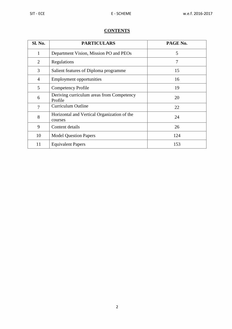
CONTENTS
Sl. No. PARTICULARS PAGE No.
1 Department Vision, Mission PO and PEOs 5
2 Regulations 7
3 Salient features of Diploma programme 15
4 Employment opportunities 16
5 Competency Profile 19
6 Deriving curriculum areas from Competency
Profile 20
7 Curriculum Outline
22
8 Horizontal and Vertical Organization of the
courses 24
9 Content details 26
10 Model Question Papers 124
11 Equivalent Papers 153

SIT - ECE E - SCHEME w.e.f. 2016-2017
3
PREFACE
The wave of liberalization and globalization has created an environment for free flow
of information and technology through fast and efficient means the world over. This has led
to shrinking of world, bringing people from different cultures and environment together,
giving rise to a global village. A shift has been taking place in India from closed economy to
knowledge based and opens economy. In order to cope-up with the challenges of handling
new technologies, materials and methods, we have to develop human resources having
appropriate knowledge, professional skills and attitude. Technical education system is one of
the significant components for human resource development. Polytechnics play an important
role in meeting the requirements of trained technical manpower for industries and field
organizations. The initiatives being taken by to revise the curriculum as per the needs of the
industry are laudable.
In order to meet the requirements of future technical manpower, constant efforts have
to be made to identify new employment opportunities, carryout activity analysis and design
need based curricula of diploma programmes. This curriculum document has been designed
by identifying job potential and competency profile of diploma holders leading to
identification of curriculum areas for the course. It is needless to emphasize that the real
success of the diploma programme depends upon its effective implementation. This will
require harnessing and effective utilization of resources. In addition to acquisition of
appropriate physical resources, the availability of competent and qualified faculty is
essential. It is time for the managers of technical education system to reorganize the system
to accept the challenges of both quantitative and qualitative expansion of technical
education.
There are various online training facilities created by the Government of India
through MHRD for the benefit of both the Teaching and Student community. Facilities like
Spoken-Tutorial, NPTEL, e-Yantra must be exploited to its fullest extent to reap the benefits
of interactive electronic media for teaching-learning process. It is hoped that polytechnics
will carry out job market research on a continuous basis to identify the new skill
requirements and develop innovative methods of course offering and thereby infuse
dynamism in the system.
PRINCIPAL & CHAIRMAN
SIT - ECE E - SCHEME w.e.f. 2016-2017
4
ACKNOWLEDGEMENTS
We gratefully acknowledge the assistance and guidance received from the following
persons:
i) Commissioner and Principal Secretary, Directorate of Technical Education,
Govt. of Tamilnadu.
ii) Principal & Chairman,Seshasayee Institute of Technology, Trichy for initiating
this project,guidance and academic freedom provided to the department in the
design of this curriculum and syllabus
iii) Academic Board members
Tmt.J. Rama, Regional officer IV, DOTE, Chennai – 25
Dr. D. Brahadeeswaran, Retired Professor, N.I.T.T.T.R, Chennai.
Dr.S. Muruganantham, Principal, Government Polytechnic College, Srirangam.
Dr.P. Sakthivel, Associate Professor/ECE, College of Engineering, Guindy,
Chennai.
Thiru S.Sangapillai, Principal/ Chairman, S.I.T, Trichy
Thiru G.M.Rajendran, General Manager(Retd),B.H.E.L.,Trichy, Management
Representative, S.I.T, Trichy.
ThiruP.Srinivasan, S.I.T Alumini, Senior Engineer, IT, Golden Rock, Trichy
for their valuable suggestions and guidance in execution of the curriculum
and syllabus.
iv) Programme Advisory committee members :
Dr.M. Santhi, Professor and Head / ECE,Saranathan College of Engineering,
Trichy.
Thiru.R. Muhammad Ehsan, Engineer, Maintenance & Service, B.H.E.L.,Trichy.
Thiru. O. Anbazhahan, P.R.O., B.S.N.L., Trichy,
Tmt.M.S.M.Sumathi, Lect(SG)/ECE, Govt. Polytechnic College, Gandarvakottai.
for their professional inputs and guidance in execution of the curriculum and
syllabus.
v) All the faculty members of the Electronics and Communication Engineering
department for their sustained effort and support in the design of this curriculum,
syllabus and documentation.
Co-ordinator

SIT - ECE E - SCHEME w.e.f. 2016-2017
5
1. DEPARTMENT VISION, MISSION, PO and PEOs
The Vision and Mission of the Department
VISION
Producing academically excellent, highly intellectual, self-motivated and ethical
Electronics and Communication Engineering Technologiststo meet the socio-economic
needs.
MISSION
To provide high quality education and to make the students employable and
become entrepreneur
To provide a unique learning environment to enable the students to face the
challenges in the field of Electronics and Communication Engineering.
To enable the students to develop technical skills as well as continuous
upgradation of techniques for reaching the heights of excellence in technical
education.
To provide ethical and value based education to meet the socio-economic needs
Program Educational Objectives
The Program Educational Objectives (PEOs) of the department of ECE are given
below:
PEO1: Possessingstrong educational background in Electronics & Communication
Engineering to identify, analyse and solve problems in the field of Electronics and
develop sophisticated communication systems.
PEO2:Adapting new ideas and technologies as a life-long learner.
PEO3:Inculcating ethical practices, dynamic leadership qualities and effective
communication skills.
PEO4: Exhibiting innovative ideas and management skills to meet the day to day
technical challenges.

SIT - ECE E - SCHEME w.e.f. 2016-2017
6
List of Program Outcomes
PO1
Engineering Knowledge: Apply the knowledge of mathematics, science and
engineering fundamental concepts appropriate to the discipline of Electronics and
Communication Engineering.
PO2 Problem Analysis: Analyse the complex engineering problems, identify and
formulate the solutions appropriate to it.
PO3
Design/Development of solutions: Design, implement and evaluate Electronics
and Communication systems for public health and safety, cultural, societal and
environmental considerations.
PO4 Conduct investigations: Design electronic circuits and conduct investigations as
well as to analyse and interpret data.
PO5 Modern Tool Usage: Use current techniques, skills and modern tools necessary for
practice.
PO6 The Engineer and Society: Apply the professional engineering practice to the
local and global issues in the society.
PO7 Environment and Sustainability: Apply the knowledge of professional
engineering solutions for the sustainable development in changing environments.
PO8 Ethics: Apply the knowledge of learnt professional ethics to social issues and
responsibilities.
PO9
Individual and Team Work: Function effectively as an individual and as
a team leader in diverse and multidisciplinary settings to accomplish a common
goal.
PO10 Communication: Communicate effectively through presentations and clear
instructions with the engineering community and society.
PO11 Project Management and Finance: Apply the engineering and management
principles to manage project as an employee and as an employer.
PO12 Life-Long Learning: Develop life-long learning for the changing technological
environment
List of PSO’s (Program Specific Outcomes)
PSO1: Apply the knowledge of mathematics, physics, chemistry, electronics and
communication to solve the complex engineering problems in Electronic Devices
and Circuits, VLSI, Microcontroller, Embedded systems, communication systems
and other associated topics.
PSO2: Select and apply modern engineering hardware and software tools to analyze
complex Electronics and Communication engineering problems

SIT - ECE E - SCHEME w.e.f. 2016-2017
7
2. R E G U L A T I O N S
DIPLOMA COURSES IN ENGINEERING
(TERM PATTERN)
(Implemented from 2016- 2017)
E – SCHEME
(Common to all Programmes)
R E G U L A T I O N S
1. Description of the Programme:
a. Full Time (3 years)
The Programme for the Full Time Diploma in Engineering shall extend over a period
of three academic years, consisting of 6 terms* and the First Year is common to all
Engineering Programmes.
The Curriculum for all the 6 Terms of Diploma Programmes have been revised and
revised curriculum is applicable for the candidates admitted from 2016 - 2017 academic
year onwards.
b. Sandwich (3½ years)
The Programme for the Diploma in Paper Technology (Sandwich) shall extend over a period
of three and half academic years, consisting of 7 terms* and the First Year is common to all
Engineering Programmes. The courses of diploma Programmes being regrouped for
academic convenience.
During 4th
and 7th
terms, the students undergo industrial training for six months.
Examination will be conducted after completion of every 6 months of industrial training
2. Condition for Admission:
The candidates shall be required to have passed in the S.S.L.C Examination of the Board of
Secondary Education, Tamilnadu.
(Or)
the Anglo Indian High School Examination with eligibility for Higher Secondary Course in
Tamilnadu
(Or)
the Matriculation Examination of Tamil Nadu.
(Or)

SIT - ECE E - SCHEME w.e.f. 2016-2017
8
Any other Examinations recognized as equivalent to the above by the Board of Secondary
Education, Tamilnadu.
Note: In addition, at the time of admission, the candidate will have to satisfy certain
minimum requirements, which may be prescribed from time to time.
3. Admission to Second year (Lateral Entry):
A pass in HSC (Academic)# or (Vocational) courses mentioned in the Higher Secondary
Schools in Tamilnadu affiliated to the Tamilnadu Higher Secondary Board with
eligibility for University Courses of study or equivalent examination, & should have
studied the following Courses
Sl. No
Programmes # H.Sc
Academic
H.Sc Vocational
Courses Studied Courses Studied
Related
courses
Vocational courses
1 All the Regular and
Sandwich Diploma
Programmes
Maths, Physics
& Chemistry
Maths, Physics
& Chemistry
(any one)
Related Vocational
Courses - Theory &
Practical
. # Subject to the approval of the AICTE
• For the Diploma Programmes related with Engineering/Technology, the related /
equivalent courses prescribed along with Practicals may also be taken for arriving the
eligibility.
• Programmes will be allotted according to merit through counseling by the Principal as
per communal reservation.
• Candidates who have studied Commerce Courses are not eligible for Engineering
Diploma Programmes.
4. Age Limit:
No Age limit.
5. Medium of Instruction:
English
6. Eligibility for the Award of Diploma:
No candidate shall be eligible for the Diploma unless he/she has undergone the
prescribed course of study for a period of not less than 3/3 ½ academic years (Full
SIT - ECE E - SCHEME w.e.f. 2016-2017
9
Time/Sandwich), affiliated to the State Board of Technical Education and Training,
Tamilnadu, when joined in First Year and 2/2 ½ years (Full Time/Sandwich), if joined
under Lateral Entry scheme in the second year and passed the prescribed examination.
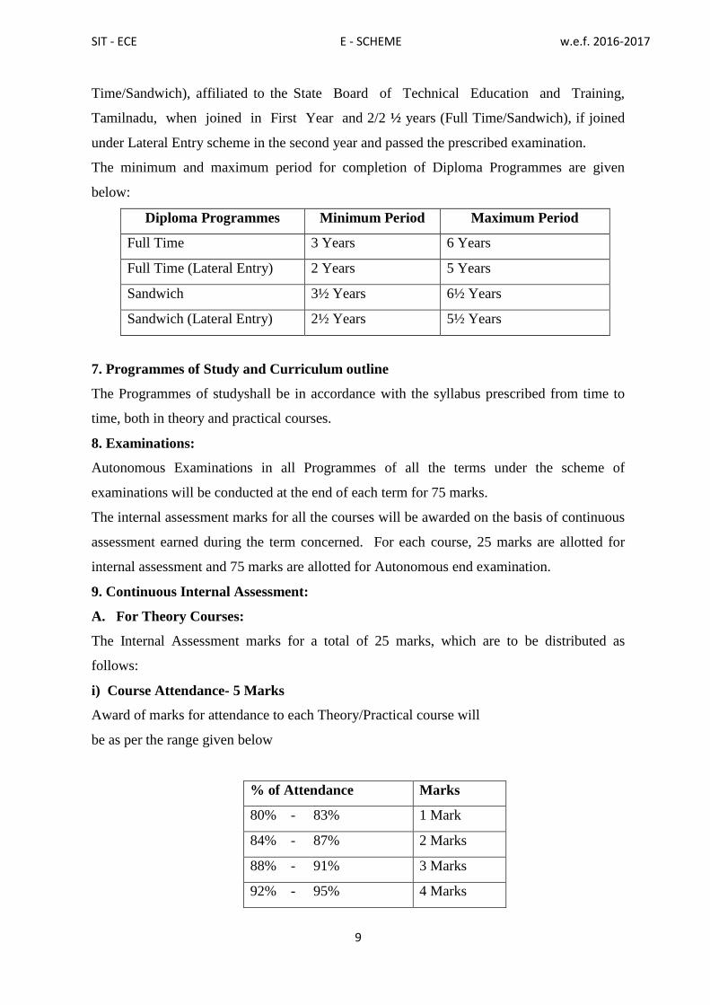
The minimum and maximum period for completion of Diploma Programmes are given
below:
Diploma Programmes Minimum Period Maximum Period
Full Time 3 Years 6 Years
Full Time (Lateral Entry) 2 Years 5 Years
Sandwich 3½ Years 6½ Years
Sandwich (Lateral Entry) 2½ Years 5½ Years
7. Programmes of Study and Curriculum outline
The Programmes of studyshall be in accordance with the syllabus prescribed from time to
time, both in theory and practical courses.
8. Examinations:
Autonomous Examinations in all Programmes of all the terms under the scheme of
examinations will be conducted at the end of each term for 75 marks.
The internal assessment marks for all the courses will be awarded on the basis of continuous
assessment earned during the term concerned. For each course, 25 marks are allotted for
internal assessment and 75 marks are allotted for Autonomous end examination.
9. Continuous Internal Assessment:
A. For Theory Courses:
The Internal Assessment marks for a total of 25 marks, which are to be distributed as
follows:
i) Course Attendance- 5 Marks
Award of marks for attendance to each Theory/Practical course will
be as per the range given below
% of Attendance Marks
80% - 83% 1 Mark
84% - 87% 2 Marks
88% - 91% 3 Marks
92% - 95% 4 Marks

SIT - ECE E - SCHEME w.e.f. 2016-2017
10
96% - 100% 5 Marks
ii) Tests # - 10 Marks
2 Tests each of 2 hours duration for a total of 50 marks are to be conducted and the marks so
obtained will be reduced to 5 marks. A Model exam covering all the five units is to be
conducted and the marks will be reduced to 5 marks
Question Paper Pattern for the Periodical Test :( Test - I & Test- II)
PART-A: 4 Questions X 2 marks - 8 marks
PART-B: 4 Questions X 3 marks - 12 marks
PART-C: 3 Questions X 10 marks - 30 marks
-------------
Total 50 marks
--------------
iii) Assignment / Online test - 10 Marks
# - From the Academic year 2016-2017 onwards.
For eachCourse, Three Assignments/ On line tests are to be given/ conducted each for 20
marks and the average marks scored should be reduced for 10 marks.
All Test Papers and Assignment notebooks after getting the signature with date from
thestudents must be kept in the safe custody in the Department for verification and audit. It
TEST
UNITS
WHEN TO
CONDUCT
MARKS DURATION
Test I
In 2 Units End of 5th
week
50 2 hours
Test II
In 2 Units End of 10th
week
50 2 hours
Test III
Model Examination - Compulsory
Covering all the 5 Units.
(Autonomous Examinations-question
paper pattern).
End of the
term
100 3 hours

SIT - ECE E - SCHEME w.e.f. 2016-2017
11
should be preserved for 2 Terms and produced to the inspection team at the time of
inspection/verification.
Total : 25 marks
B. For Practical Courses:
The Internal Assessment marks for a total of 25 marks are to be distributed
as follows: -
a) Attendance
5 Marks (Procedure for the
Award of marks is the
same as theory courses)
b) Procedure / Observation and
tabulation/ Other Practical related work
10 Marks
c) Record writing 10 Marks
TOTAL 25 Marks
• All the Experiments/Exercises indicated in the syllabus should be completed and the
same to be given for final Autonomous examinations.
• The Record for every completed exercise should be submitted in the subsequent
Practical classes and marks should be awarded for 20 for each exercise as per the above
allocation.
• At the end of theterm, the average marks of all the exercises should be calculated for 20
marks and the marks awarded for attendance is to be added to arrive the internal assessment
marks for Practical.
• The students have to submit the duly signed bonafide record note book/file during
the Practical Autonomous Examinations.
• All the marks awarded for assignments, tests and attendance should be entered in
thePersonal Log Book of the staff, who is handling the subject. This is applicable to both
Theory and Practical courses.
10. Life and Employability Skills Practical:

SIT - ECE E - SCHEME w.e.f. 2016-2017
12
Life and Employability Skills Practical with more emphasis is being introduced in IV
Term for Circuit Branches and in V Term for other branches of Engineering.
Much Stress is given to increase the employability of the student
Internal Assessment Mark : 25 Marks
11. Project Work:
The students of all the Diploma Programmes have to do a Project Work as part of the
Curriculum and in partial fulfilment for the award of Diploma by the State Board of
Technical Education and Training, Tamilnadu. The Project work must be reviewed twice
in the same semester.
a) Internal assessment mark for Project Work:
Project Review I 10 marks
Project Review II 10 marks
Attendance 05 marks (Procedure for the Award of
marks is the same as theory courses)
Total 25 marks
Proper records are to be maintained for the two Project Reviews, and they should be
preserved for 2 Semesters and produced to the inspection team at the time of
inspection/verification.
b) Allocation of Mark for Project Work & Viva Voce in Board Examination:
Viva Voce 30 marks
Marks for Report Preparation, Demonstration 35 marks
Written Test Mark (from 2 topics for 30
minutes duration)
10 Marks
Total 75 marks

SIT - ECE E - SCHEME w.e.f. 2016-2017
13
Written Test Mark :
i) Environment Studies: 2 questions X 2 ½ marks =5 marks
ii) Disaster Management: 2 questions X 2 ½ marks = 5 marks
Total = 10marks
Selection of Questions should be from Question Bank, by the External Examiner.
No choice to be given to the candidates.
12. Scheme of Examinations:
The Scheme of examinations for courses is given in Curriculum outline
13. Criteria for Pass:
1. No candidate shall be eligible for the award of Diploma unless he/she has undergone the
prescribed course of study successfully in an institution approved by AICTE and affiliated to
the State Board of Technical Education & Training, Tamil Nadu and pass all the courses
prescribed in the curriculum.
2. A candidate shall be declared to have passed the examination in a course if
he/she secures not less than 40% in theory courses and 50% in practical courses out of the
total prescribed maximum marks including both the Internal Assessment and the
Autonomous Examinations marks put together, subject to the condition that he/she
secures at least a minimum of 30 marks out of 75 marks in the Autonomous Theory
Examinations and a minimum of 35 marks out of 75 marks in the Autonomous Practical
Examinations.
14. Classification of successful candidates:
Classification of candidates who will pass out the final examinations from April 2019
onwards (Joined in first year in 2016-2017 / Joined in second year in 2017-2018) will be
done as specified below.
First Class with Superlative Distinction:
A candidate will be declared to have passed in First Class with Superlative Distinction if
he/she secures not less than 75% of the marksin all the courses and passes all the terms in
the first appearance itself and passes all courses within the stipulated period of study 3/ 3½
years (Full Time/Sandwich) without any break in study.

SIT - ECE E - SCHEME w.e.f. 2016-2017
14
First Class with Distinction:
A candidate will be declared to have passed in First Class with Distinction if he/she
secures not less than 75% of the aggregate of marks in all the terms put together and passes
all the terms except the I and II terms in the first appearance itself and passes all the courses
within the stipulated period of study 3/3½ years (Full Time/Sandwich) without any break in
study.
First Class:
A candidate will be declared to have passed in First Class if he/she secures not less than
60% of the aggregate marks in all terms put together and passes all the courses within the
stipulated period of study 3/3½ years (Full Time/Sandwich) without any break in study.
Second Class:
All other successful candidates will be declared to have passed in Second Class.
15. Duration of a period in the Class Time Table:
The duration of each period of instruction is 1 hour and the total period of instruction hours
excluding interval and Lunch break in a day should be uniformly maintained as 7 hours
corresponding to 7 periods of instruction (Theory & Practical).
************************

SIT - ECE E - SCHEME w.e.f. 2016-2017
15
3. SALIENT FEATURES OF THE DIPLOMA PROGRAMME IN
ELECTRONICSAND COMMUNICATION ENGINEERING
Name of the Programme : Diploma Programme in Electronics and
communication Engineering
Duration of the Programme : Three years (Six Semesters)
Entry Qualification : Matriculation or equivalent as prescribed by State
Board of Technical Education,Tamilnadu
Intake: : 60 + 12(First Year - 60, Lateral Entry – 12)
Pattern of the Programme : Semester Pattern
Ratio Between Theory &
Practical Classes
: 50: 50 (Approx.)

SIT - ECE E - SCHEME w.e.f. 2016-2017
16
4. EMPLOYMENT OPPORTUNITIES AND ACTIVITY PROFILE OF
DIPLOMA HOLDERS IN ELECTRONICS AND COMMUNICATION
ENGINEERING
It is observed that employment in government/public sector undertakings are
dwindling day by day. Keeping present scenario in view, following employment
opportunities are visualized in different sectors of employment for diploma holders
in electronics and communication engineering.
(A) EMPLOYMENT OPPORTUNITIES
Various Departments/ organizations/boards and corporations
1) Tele-Communication Engineering and related Departments
2) AIR, Doordarshan,
3) Overseas Communication,
4) Mine Communication,
5) Radar and Wireless,
6) Railways,
7) Defence Services, Para-military Forces and Police
8) Civil Aviation
9) Defence Research and Development Organizations (DRDO)
10) Electricity Boards and Corporations etc.
11) Engineering Institutions
12) Research and Development Department
13) Maintenance Department.
14) Airport Authority of India (Airports)
Industry:
15) Communication Industry manufacturing wireless mobile equipment
for defense and Paramilitary forces
16) PCB Design and Fabrication Industry
17) Consumer Electronics Industry
18) Electronic Components and Devices Manufacturing and Installation
Organizations.
19) Computer Assembling and Computer Peripheral Industry.
20) Computer Software Areas for Electronic Design and Semi-Conductor
Manufacturing Industry
21) Instrumentation and Control Industries
22) Internet Server Provides
23) Food Product Industries
24) Construction Industries
25) Agro and dairy Industry
26) Public Sector Undertakings ( like BHEL,BEL, HAL, etc)

SIT - ECE E - SCHEME w.e.f. 2016-2017
17
27) D.T.H component and Fabrication factory
28) Mobile Phone Assembly Industries
29) Medical Electronics Industry
30) EPABX/ Telephone Exchange Manufacturing Industries
31) Computer Software Areas for Electronic Design and Semi-Conductor
Manufacturing Industry
32) Computer Assembling and Computer Peripheral Industry;
33) Automobile Industry
34) Automation and Control Industry (viz bottling plant, cement plant,
automobile units, escalators etc.
Development/Testing Laboratories/Organizations
35) Electronics Service Centres
36) Opto Electronics (Medical & Comm.)
37) Computer Networking
38) Hospitals
39) Educational Institutions (Engineering Institutes, ITIs, Vocational Schools
etc)
40) Sales and Services of Electronic Gadgets from Small Scale Industries
41) Call Centres
Self Employment
Marketing and Sales (Distributors - whole sale and retailers)
Service Sector(repair and Maintenance; job work)
Cable laying and jointing DBs etc.
Preparing Simulated Models
Manufacturing Unit (e.g.- Bulb manufacturing, chalk manufacturing, circuit
manufacturing units etc)
(B) JOB/ACTIVITY PROFILE
The diploma holders in Electronics and Communication Engineering (ECE)
generally get employed in manufacturing, assembly industries of consumer electronics,
manufacturing of wireless equipment, Doordarshan and All India Radio (AIR), defence
organizations, marketing and servicing organizations. Some of the activities they perform
are listed below:
1) Reading, interpreting and preparing drawings and circuits in electronics and
related fields
2) Supervising the fabrication and assembly work at sub-assembly and final
assembly
3) Selecting components and devices for simple applications
4) Testing the materials used in assembly work.
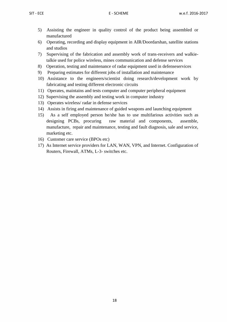
SIT - ECE E - SCHEME w.e.f. 2016-2017
18
5) Assisting the engineer in quality control of the product being assembled or
manufactured
6) Operating, recording and display equipment in AIR/Doordarshan, satellite stations
and studios
7) Supervising of the fabrication and assembly work of trans-receivers and walkie-
talkie used for police wireless, mines communication and defense services
8) Operation, testing and maintenance of radar equipment used in defenseservices
9) Preparing estimates for different jobs of installation and maintenance
10) Assistance to the engineers/scientist doing research/development work by
fabricating and testing different electronic circuits
11) Operates, maintains and tests computer and computer peripheral equipment
12) Supervising the assembly and testing work in computer industry
13) Operates wireless/ radar in defense services
14) Assists in firing and maintenance of guided weapons and launching equipment
15) As a self employed person he/she has to use multifarious activities such as
designing PCBs, procuring raw material and components, assemble,
manufacture, repair and maintenance, testing and fault diagnosis, sale and service,
marketing etc.
16) Customer care service (BPOs etc)
17) As Internet service providers for LAN, WAN, VPN, and Internet. Configuration of
Routers, Firewall, ATMs, L-3- switches etc.

SIT - ECE E - SCHEME w.e.f. 2016-2017
19
5. COMPETENCY PROFILE OF DIPLOMA HOLDERS IN ELECTRONICS
AND COMMUNICATION ENGINEERING
Keeping in view the job opportunities, activity profile and various domains of
learning, the diploma holders in Electronics and Communication Engineering should have
following competency profile in terms of knowledge and skills:
Knowledge of different electronic devices, components, materials and instruments
used in manufacturing and testing of electronic products
Understanding the basic principles of electronics devices and circuits, Linear
integrated circuits and industrial electronics
Skills in reading and interpreting drawings pertaining to electronic circuits,
instruments, and equipment
Understanding the basic principles of Electrical Circuits and Machines and
Measuring Instruments
Understanding the basic principles of digital electronics; VLSI, Microcontroller and
Embedded Systems.
Understanding of basic principles of communication engineering and advanced
communication systems; audio video systems
Knowledge of Radar Engineering and Optical Fiber Communication
Proficiency in oral and written communication, technical report writing, managing
relationship with juniors, peers and seniors for effective functioning in the world of
work
Knowledge and awareness of upcoming technologies of their field like
PLC,SCADA & DAS System
Knowledge of latest trends in the field of television engineering, Bio medical and
telemedicine and digital image processing
Knowledge of programming in C and maintenance of computer hardware servicing
and networking
Understanding, designing and analyzing the electronic circuits using simulation
software.
Creating Awareness about the environment, disaster management and how to
Manage men, material, equipment and techniques to become an entrepreneur

SIT - ECE E - SCHEME w.e.f. 2016-2017
20
6. DERIVING CURRICULUM AREAS FROM COMPETENCY PROFILE
Following curriculum areas have been derived from competency profile as identified in
Section 3:
Sl.
No. Competency Profile Curriculum Area/Courses
1
Knowledge of different electronic devices,
understanding the different types of electronic
circuits, integrated circuits
Electronic Devices and its
applications
Electronic Circuits
Linear Integrated Circuits
2 Understanding the basic principles of Digital
electronics Digital Electronics
3
Knowledge of electrical circuits, networks
theorems, DC and AC, Fundamentals,
transformers, DC generators and DC motors,
Knowledge of measuringdifferent parameters of
electronic devices, components and materials
used in manufacturing and testing of electronic
products
Electrical Circuits and
Instrumentation
4
Knowledge of basics of communication, various
types of networks, transmission lines, antennas
and propagation Knowledge of latest trends in
the field of communication. (RADAR, digital
communication, fiber optics, satellite
communication, etc.)
Communication Engineering
Advanced Communication
Systems
5
Knowledge of ARM and THUMB instructions,
coding, programming in embedded c and
assembly language using ARM and THUMB
instructions, industrial oriented applications with
interface. Programming for Real Time
application in RTOS and ability to develop the
system requirements.
Embedded systems
6 Knowledge and skills in programming C‟ Programming
7 Understanding, designing and analyzing the
electronic circuits using simulation software.
Electronic Circuit Design
and Simulation Lab

SIT - ECE E - SCHEME w.e.f. 2016-2017
21
Sl.
No. Competency Profile Curriculum Area/Courses
8
Knowledge of microprocessor &
microcontroller and their applications in
Electronic System.
Microcontroller
9
Knowledge of digital design, implementation
of any digital circuits and simulates the digital
circuits without using kit. Latest technology in
field of digital design
VLSI
10
Understanding the principles of power devices,
circuits, converters, choppers, inverters, PLC,
CNC and Robotics
Industrial Electronics
PLC
11
Knowledge and skills in using information
technology tools for information storage,
retrieval and dissemination, making use of
computer application software and Networking
Computer hardware
Servicing and
Networking Lab
12
Understanding the fundamentals of TV, TV
transmitter, TV receiver and advanced
Television Systems.
Television Engineering
13 Knowledge of Bio-medical equipment and
Telemedicine.
Biomedical
Instrumentation
14
Proficiency in oral and written
communication, technical report writing,
managing relationship with juniors, pears and
seniors for effective functioning.
Life Skills and
Employability Lab
15
Understanding the basic principles of
managing men, material and equipment and
techniques of achieving economy and quality
Entrepreneurship
Development
Disaster Management
16
Awareness about the environment, use of non-
conventional energy sources, external financial
and technical support system, adopting energy
conservation techniques
Environmental Studies
17
Competency in solving simple problems
related to various functional areas of
Electronics Engineering, making a prototype
model
Project work
SIT - ECE E - SCHEME w.e.f. 2016-2017
22
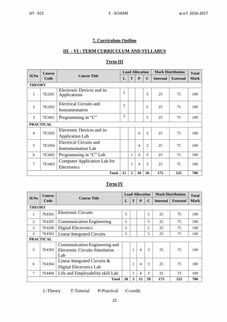
7. Curriculum Outline
III - VI : TERM CURRICULUM AND SYLLABUS
Term III
Sl.No Course
Code Course Title
Load Allocation Mark Distribution Total
Mark L T P C Internal External
THEORY
1 7E3201 Electronic Devices and its Applications
5 5 25 75 100
2 7E3202 Electrical Circuits and
Instrumentation 5 5 25 75 100
3 7E3401 Programming in “C” 5 5 25 75 100
PRACTICAL
4 7E3203 Electronic Devices and its
Application Lab 6 3 25 75 100
5 7E3204 Electrical Circuits and
Instrumentation Lab 4 2 25 75 100
6 7E3402 Programming in “C” Lab 1 4 3 25 75 100
7 7E3403 Computer Application Lab for
Electronics 1 4 3 25 75 100
Total 15 2 18 26 175 525 700
Term IV
Sl.No Course
Code Course Title
Load Allocation Mark Distribution Total
Mark L T P C Internal External
THEORY
1 7E4301 Electronic Circuits 5 5 25 75 100
2 7E4205 Communication Engineering 5 5 25 75 100
3 7E4206 Digital Electronics 5 5 25 75 100
4 7E4302 Linear Integrated Circuits 5 5 25 75 100
PRACTICAL
5 7E4303
Communication Engineering and
Electronic Circuits Simulation
Lab
1 4 3 25 75 100
6 7E4304 Linear Integrated Circuits &
Digital Electronics Lab 1 4 3 25 75 100
7 7E4404 Life and Employability skill Lab 1 4 3 25 75 100
Total 20 3 12 29 175 525 700
L-Theory T-Tutorial P-Practical C-credit

SIT - ECE E - SCHEME w.e.f. 2016-2017
23
Term V
Sl.No Course
Code Course Title
Load Allocation Mark Distribution Total
Mark L T P C Internal External
THEORY
1 7E5305 Advanced Communication systems 5 5 25 75 100
2 7E5306 Microcontroller 5 5 25 75 100
3 7E5307 Very Large Scale Integration 5 5 25 75 100
4
7E5308.1
7E5308.2
7E5308.3
Elective I
(i) Digital Communication
(ii) Biomedical
Instrumentation
(iii) Electronic System
Design
5 5 25 75 100
PRACTICAL
5 7E5309 Advanced Communication
systems Lab 1 4 3 25 75 100
6 7E5310 Microcontroller Lab 1 4 3 25 75 100
7 7E5311 Very Large Scale Integration
Lab 1 4 3 25 75 100
Total 20 3 12 29 175 525 700
Term VI
Sl.No Course
Code Course Title
Load Allocation Mark Distribution Total
Mark L T P C Internal External
THEORY
1 7E6312 Embedded Systems 5 5 25 75 100
2 7E6313 Industrial Electronics 5 5 25 75 100
3 7E6314.1
7E6314.2
7E6405
Elective II
(i) Television Engineering
(ii) Mobile Communication
(iii) Computer Hardware
Servicing and Networking
5 5 25 75 100
PRACTICAL
4 7E6315 Embedded Systems Lab 1 4 3 25 75 100
5 7E6316 Industrial Electronics and PLC
Lab 6 3 25 75 100
6 7E6406 Computer Hardware Servicing
and Networking Lab 1 4 3 25 75 100
7 7E6317 Project Work 4 2 25 75 100
Total 15 2 18 26 175 525 700

SIT - ECE E - SCHEME w.e.f. 2016-2017
24
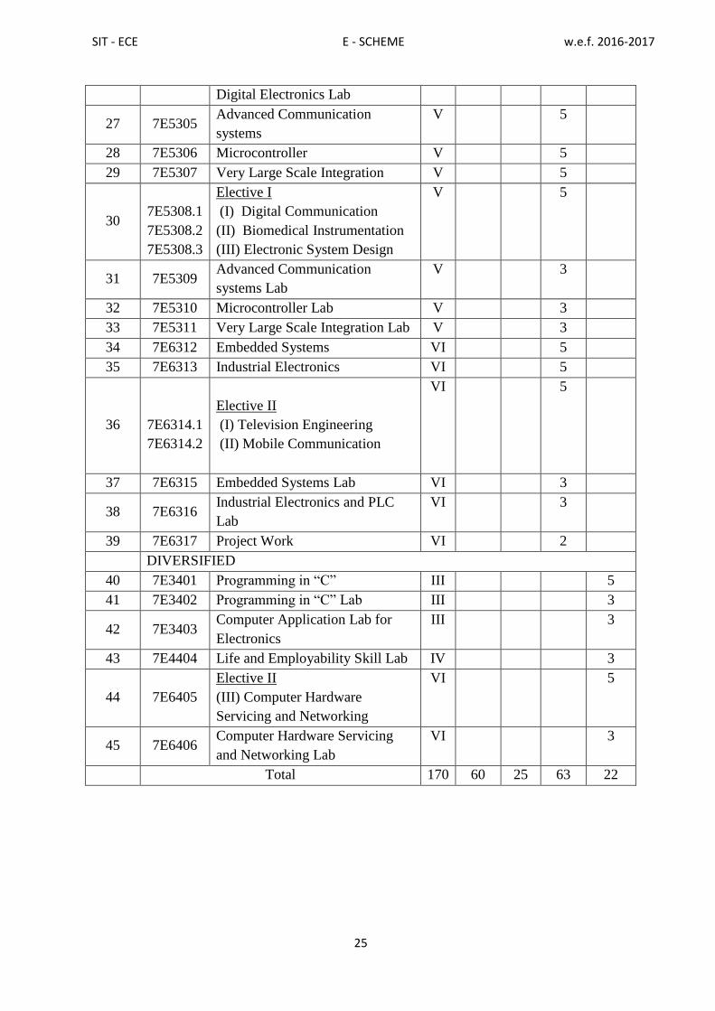
10. HORIZONTAL AND VERTICAL ORGANISATION OF THE COURSES (ECE)
SL.NO. COURSE
CODE COURSE
TE
RM
CREDITS
Fo
un
dat
ion
Co
re
Ap
pli
ed
Div
ersi
fied
FOUNDATION
1 7E1101 Communication English-I I 4
2 7E1102 Engineering Mathematics-I I 7
3 7E1103 Engineering Physics- I I 5
4 7E1104 Engineering Chemistry-I I 5
5 7E1105 Engineering Physics Practical-I I 1
6 7E1106 Engineering Chemistry Practical-I I 1
7 7E1107 Engineering Graphics - I I 4
8 7E1108 Workshop Practice I 2
9 7E2101 Communication English-II II 5
10 7E2102 Engineering Mathematics-II II 5
11 7E2103 Applied Mathematics II 5
12 7E2104 Engineering Physics-II II 5
13 7E2105 Engineering Chemistry-II II 5
14 7E2106 Engineering Physics Practical-II II 1
15 7E2107 Engineering Chemistry Practical-
II
II 1
16 7E2108 Engineering Graphics - II II 4
CORE
17 7E3201 Electronic Devices and its
Applications
III 5
18 7E3202 Electrical Circuits and
Instrumentation
III 5
19 7E3203 Electronic Devices and its
Application Lab
III 3
20 7E3204 Electrical Circuits and
Instrumentation Lab
III 2
21 7E4205 Communication Engineering IV 5
22 7E4206 Digital Electronics IV 5
APPLIED
23 7E4301 Electronic Circuits IV 5
24 7E4302 Linear Integrated Circuits IV 5
25 7E4303
Communication Engineering and
Electronic Circuits Simulation
Lab
IV 3
26 7E4304 Linear Integrated Circuits & IV 3
SIT - ECE E - SCHEME w.e.f. 2016-2017
25
Digital Electronics Lab
27 7E5305 Advanced Communication
systems
V 5
28 7E5306 Microcontroller V 5
29 7E5307 Very Large Scale Integration V 5
30
7E5308.1
7E5308.2
7E5308.3
Elective I
(I) Digital Communication
(II) Biomedical Instrumentation
(III) Electronic System Design
V 5
31 7E5309 Advanced Communication
systems Lab
V 3
32 7E5310 Microcontroller Lab V 3
33 7E5311 Very Large Scale Integration Lab V 3
34 7E6312 Embedded Systems VI 5
35 7E6313 Industrial Electronics VI 5
36
7E6314.1
7E6314.2
Elective II
(I) Television Engineering
(II) Mobile Communication
VI 5
37 7E6315 Embedded Systems Lab VI 3
38 7E6316 Industrial Electronics and PLC
Lab
VI 3
39 7E6317 Project Work VI 2
DIVERSIFIED
40 7E3401 Programming in “C” III 5
41 7E3402 Programming in “C” Lab III 3
42 7E3403 Computer Application Lab for
Electronics
III 3
43 7E4404 Life and Employability Skill Lab IV 3
44 7E6405
Elective II
(III) Computer Hardware
Servicing and Networking
VI 5
45 7E6406 Computer Hardware Servicing
and Networking Lab
VI 3
Total 170 60 25 63 22
SIT - ECE E - SCHEME w.e.f. 2016-2017
26
DETAILED SYLLABUS
III – TERM

SIT - ECE E - SCHEME w.e.f. 2016-2017
27
7E3201 - ELECTRONIC DEVICES AND ITS APPLICATIONS
Rationale:
This course gives the knowledge of the fundamental concepts of basic electronics. It
helps the students to understand the basics of passive and active components, conductors,
semiconductors and insulators, extrinsic and intrinsic semi-conductors, p-n junction, Zener
diodes, tunnel diodes, LEDs, varactor diodes, LCD, optocoupler. Understanding the working
of transistors in various configurations; understanding of FETs and MOSFET, SCR, TRIAC,
DIAC etc. is vital for effective functioning in the field of electronic service industry.
Course Objectives:
Attheendofthecourse,thestudentswillbeableto
Understand the atomic structures, semiconductors, PN junction diode and zener
diode
Understand the working principle of different types of rectifiers, filters, clippers,
clampers and special purpose diodes
Differentiate various transistor configurations and understand the working principle
of amplifiers and oscillators.
Understand the structure, principle and characteristics of FET, MOSFET and UJT
Understand the structure, principle and characteristics of SCR, DIAC, and TRIAC
Understand the operation of multivibrators.
Scheme of Instruction and Examination
Course code Instruction Examinations
7E3201
Hours/
week
Hours/
Term Credits
Marks Duration
Internal External Total 3 Hrs
5 75 5 25 75 100
UNITS - ALLOCATION OF HOURS AND MARKS
Unit no. Topics Hours Marks
I Semiconductor and Diodes 12 15
II Rectifiers, Clippers, Clampers and Special Purpose Diodes 14 15
III Transistor, Amplifiers, Oscillators 13 15
IV FET, MOSFET, UJT 13 15
V SCR, DIAC, TRIAC &Multivibrators 13 15
Cycle Tests, Model Exam& Revision classes
(2+2+3+3) 10
-
Total 75 75

SIT - ECE E - SCHEME w.e.f. 2016-2017
28
7E3201 - ELECTRONIC DEVICES AND ITS APPLICATIONS
CONTENT DETAILS
Unit-1 SEMICONDUCTOR AND DIODES:
1.1Atomic structure, energy of an electron, valence electrons, free electrons, Bohr's atomic
model, energy levels, energy bands, important energy bands in solids, classification of
solids and energy bands.
1.2 Semiconductor -Bonds in semiconductor, commonly used semiconductors, Intrinsic
semiconductor, extrinsic semiconductor, N type semiconductor, P type semiconductor,
drift current & diffusion current, PN junction diode – forward and Reverse bias
characteristics.
1.3 Zener diode -Principle-characteristics - zener break down-avalanche break down- zener
Diode as a voltage regulator –applications- specifications
Unit-2RECTIFIERS, CLIPPERS, CLAMPERS AND SPECIAL PURPOSE DIODES
2.1 Rectifier – introduction-classification of rectifiers-half wave rectifier-full wave rectifier
(center tapped, bridge)-(no mathematical equations)-comparison-Applications-filters-
C, LC and PI filters. Block diagram of regulated power supply
2.2 Clipper positive clipper, negative clipper, biased clipper, combination clipper,
application of clipper. Clamper- positive clamper, negative clamper
2.3 Special purpose Diodes: Light emitting diodes- characteristics- advantages of LED,
multicolor LEDs, seven segment displays, photo diode- characteristics, applications,
opto isolator, tunnel diode, varactor diode, Shockley diodes
Unit-3 TRANSISTOR, AMPLIFIERS, OSCILLATORS
3.1 Transistor – NPN and PNP transistor – operation-transistor as an amplifier- transistor as
a switch –CB, CE, CC configurations – characteristics - comparison between three
configurations in terms of input impedance, output impedance, current gain, voltage
gain. Transistor biasing – fixed bias, collector base bias, self-bias
3.2 Amplifiers- classification of amplifiers- RC coupled amplifier – emitter follower and its
application – negative feedback Concept, effect of negative feedback – types of
negative feedback connections.
3.3 Oscillators-Classifications – Condition for oscillations (Barkhausen criterion) – General
form of LC oscillator – Hartley Oscillator – Colpitts Oscillator – RC Phase shift
oscillator- Crystal oscillator
Unit-4 FET, MOSFET, UJT
4.1Field Effect Transistor – construction – working principle of FET – difference Between
FET and BJT – classification of FET – characteristics of FET – Applications – FET
amplifier (common source amplifier).
4.2 MOSFET– types & characteristics of N channel MOSFET and P channel MOSFET-
Characteristics of enhancement and depletion mode MOSFET – MOSFET as a switch.
4.3 Uni Junction Transistor– construction – equivalent circuit – operation – Characteristics – UJT as
a relaxation oscillator

SIT - ECE E - SCHEME w.e.f. 2016-2017
29
Unit-5 SCR, DIAC, TRIAC
5.1 SCR -Structure – working principle – VI-characteristics -Two transistor analogies - Half
wave controlled rectifier.
5.2 TRIAC-Structure – working principle - VI-characteristics DIAC – Structure – working
principle- characteristics – DIAC as bi- directional switch. Applications of SCR,
TRIAC, DIAC
5.3 Multivibrators – Astable, Monostable and Bistable
Text Books:
Reference Books :
Online Resources
http://www.learnabout-electronics.org/
http://www.electronics-tutorials.ws/
http://nptel.ac.in/courses/117103063/
http://freevideolectures.com/Course/2261/Basic-Electronics-and-Lab/39
Course Outcomes:
After learning the course the student will be able to:
CO1 Familiar with atomic structure, Semiconductor PN diode, & Zener diode
CO2 Able to understand the working principle of Rectifiers, Clippers, Clampers and
Special purpose diodes
CO3 Able to analyze Transistors, Amplifiers and Oscillators
CO4 Able to understand the structure and working principle ofFET, MOSFET & UJT
CO5 Able to understand the structure and working principle of SCR, DIAC, TRIAC
&multivibrators
Sl.No. Title Author Publisher
1
Principles of Electronics V.K. Mehta & Rohit Mehta
S.Chand& Company
New Delhi
3rd
edition 2014
2 Electronics Devices & Circuits
Salivahanan S, N.Suresh
Kumar
Mcgraw Hill Education
3rd
Edition, 2012
Sl.No. Name of the Book Author Publisher
1 Principle of Electronics V.K. Mehta S.Chand& Co New Delhi
6th
edition 2001
2 Electronics principles Malvino Tata McGraw Publication
6th
edition 2000
3
Electronics Devices and
Circuits
Allen Mottershed Tata McGraw Hill Publication
1st edition 1973
4
Electronics Devices and
Circuits
Jacob Millman and
Halkies
Tata McGraw Hill Publication
2nd
edition 2000
5 Optical Fiber
Communication
Gerd Keiser. S.Chand& Co New Delhi
4th
edition 2008

SIT - ECE E - SCHEME w.e.f. 2016-2017
30
7E3202 - ELECTRICAL CIRCUITS AND INSTRUMENTATION
Rationale:
Thiscourse enables thestudentsto learn theconceptsofDC,ACcircuits,
fundamentalsof Electrical Machines, workingprinciples ofanalog and digital
electronicmeasuring instruments. The introduction of this course will enable the students
to understand the fundamentals ofelectrical circuits and machines and also make them to
learn a wide range of electronic measuring instruments.
Course Objectives:
At the end of the course, the students will be able to
Understand ohm‟s law, Kirchhoff‟ s laws and circuit theorems
Learn about series and parallel Circuits.
Learn various terms related to AC circuits and understand concept of AC circuits
Learn about series and parallel resonance circuits.
Study about transformer and its working.
Understand the working of DC machine, induction motor and stepper motor
Understand the basic measuring instruments.
Learn about bridge circuits.
Discuss about CRO and its types.
Learn about transducers and test instruments
Scheme of Instruction and Examination
Course code Instruction Examinations
7E3202
Hours/
week
Hours/
Term Credits
Marks Duration
Internal External Total 3 Hrs
5 75 5 25 75 100
UNITS - ALLOCATION OF HOURS AND MARKS
Unit no. Topics Hours Marks
I DC Circuits and Theorems 13 15
II AC Circuits and Resonance 13 15
III Transformers and Machines 13 15
IV Measuring Instruments and CRO 13 15
V Transducers , Sensors &Test Instruments 13 15
Cycle Tests, Model Exam& Revision classes
(2+2+3+3) 10
-
Total 75 75

SIT - ECE E - SCHEME w.e.f. 2016-2017
31
7E3202 - ELECTRICAL CIRCUITS AND INSTRUMENTATION
CONTENT DETAILS
Unit-1 D.C. CIRCUITS AND THEOREM
1.1Definition and unit for voltage, current, power, resistance, conductance, resistivity-
Laws of resistance-Ohm‟s law– only simple problems in ohm‟s law- Kirchhoff‟s
current law and voltage law.
1.2 Series circuits–parallel circuits, series parallel circuits. Mesh Method (simpleproblems)
Capacitors in series and parallel.
1.3Thevenin‟s - Norton‟s theorems, Super position and Maximum power transfer
theorem–Statement and Explanation (simple problems)
Unit-2 A.C. CIRCUITS AND RESONANCE
2.1 A.C Circuits: AC through single pure resistance, pure inductance, pure capacitance,
voltage and current relationship and (to mention only) the equation for power and
powerfactor in each case. Definition for impedance, reactance, admittance,
conductance, impedance, phase angle, power factor and power.
2.2 AC circuits– Derivation for impedance and admittance, power and power factor in
Series R-L, R-C, R-L-C circuits. Analysis of Parallel R-L circuit, R-C circuit, R-LC
circuit (qualitative treatment only. Resonance- series resonance – parallel resonance-
condition for resonance-resonant,frequency-Q factor – resonance curve-bandwidth-
applications of resonance.
Unit-3 TRANSFORMERS AND MACHINES
3.1Transformer– Ideal transformer– construction - working principle–EMF equation
losses in transformer- core loss, copper loss- Efficiency- Regulation OC, SC test
on transformer-List of applications (qualitative treatment only)
3.2MACHINES:Faraday‟s laws of electromagnetic induction. D.C. Machines - DC–
Generator –Working principle– Types (characteristics not required) – Applications.
DC motor- working principle – types (characteristics not required) - applications
(qualitative treatment only)
3.3 Single phase induction motor- types (to list only) – construction and principle of
operation of capacitor start induction motor-Applications- stepper motor-working
principle-uses (qualitative treatment only)- Universal Motor (qualitative treatment
only) Difference between single phase and three phase supplies
Unit-4 MEASURING INSTRUMENTS AND CRO
4.1 MEASURING INSTRUMENTS:Definitionfor Measurement, Instrument- Errors in
Measurement - Calibration- Indicating instruments– Basic forcesfor indicating
instruments - construction and operation of permanent magnet moving coil
Instrument-Advantages – Disadvantages of PMMC- Shunts and Multipliers- DC
ammeter-DC voltmeter-voltmeter sensitivity.
4.2 Bridges- Types (to list only) -Wheat stone bridge - applications-Universal impedance
bridge arrangements tomeasure R, L, C
4.3CRO- Block diagram and principle of operation of CRO- operation of CRT
Electrostatic focusing- Electrostatic deflection (no derivation)- Block diagram of
vertical deflection system-Applications of CRO- Types of CRO (to list only) –
Block diagram and operation of dual trace CRO- Dual beam CRO-Comparison
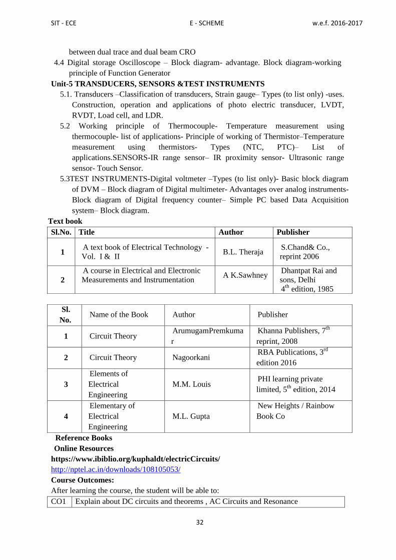
SIT - ECE E - SCHEME w.e.f. 2016-2017
32
between dual trace and dual beam CRO
4.4 Digital storage Oscilloscope – Block diagram- advantage. Block diagram-working
principle of Function Generator
Unit-5 TRANSDUCERS, SENSORS &TEST INSTRUMENTS
5.1. Transducers –Classification of transducers, Strain gauge– Types (to list only) -uses.
Construction, operation and applications of photo electric transducer, LVDT,
RVDT, Load cell, and LDR.
5.2 Working principle of Thermocouple- Temperature measurement using
thermocouple- list of applications- Principle of working of Thermistor–Temperature
measurement using thermistors- Types (NTC, PTC)– List of
applications.SENSORS-IR range sensor– IR proximity sensor- Ultrasonic range
sensor- Touch Sensor.
5.3TEST INSTRUMENTS-Digital voltmeter –Types (to list only)- Basic block diagram
of DVM – Block diagram of Digital multimeter- Advantages over analog instruments-
Block diagram of Digital frequency counter– Simple PC based Data Acquisition
system– Block diagram.
Text book
Reference Books
Online Resources
https://www.ibiblio.org/kuphaldt/electricCircuits/
http://nptel.ac.in/downloads/108105053/
Course Outcomes:
After learning the course, the student will be able to:
CO1 Explain about DC circuits and theorems , AC Circuits and Resonance
Sl.No. Title Author Publisher
1 A text book of Electrical Technology -
Vol. I & II B.L. Theraja
S.Chand& Co.,
reprint 2006
2
A course in Electrical and Electronic
Measurements and Instrumentation
A K.Sawhney
Dhantpat Rai and
sons, Delhi
4th
edition, 1985
Sl.
No. Name of the Book Author Publisher
1 Circuit Theory ArumugamPremkuma
r
Khanna Publishers, 7th
reprint, 2008
2 Circuit Theory Nagoorkani RBA Publications, 3
rd
edition 2016
3
Elements of
Electrical
Engineering
M.M. Louis PHI learning private
limited, 5th
edition, 2014
4
Elementary of
Electrical
Engineering
M.L. Gupta
New Heights / Rainbow
Book Co

SIT - ECE E - SCHEME w.e.f. 2016-2017
33
CO2 Explain about Transformers and Machines
CO3 Understand the functions of Measuring Instruments and CRO
CO4 Identify the Transducers and its functions, able to understand working principle of
Test Instruments
7E3401 - PROGRAMMING IN “C”
Rationale:
C‟ is the most widelyused computer language,which is being taught as a core
course. C is general
purposestructurallanguagethatispowerful,efficientandcompact,whichcombinesfeaturesof
high levellanguageandlow-
levellanguage.ItisclosertobothManandMachine.Duetothisinherent
flexibilityandtoleranceit
issuitablefordifferentdevelopmentenvironments.Duetothesepowerful
features,Chasnotlostitsimportanceandpopularityinrecentlydevelopedandadvancedsoftwa
re
industry.Ccanalsobeusedforsystemlevelprogramminganditisstillconsideredasfirstpriority
programminglanguage.ThiscoursecoversthebasicconceptsofC.Thiscoursewillactas
“Programming concept developer” for students. It will also act as “Backbone” for
courses like OOPS, VisualBasic,WindowsProgramming,JAVAetc.
Course Objectives:
At the end of the course, the students will be able to
Define Program, Algorithm and flow chart
understand various program development steps
develop algorithm and flow chart for simple problems.
Describe the concepts of Constants, Variables, Data types and operators.
Develop programs using input and output operations.
Understand the structure and usage of different looping and branching
statements.
Define arrays and string handling functions.
understand user-defined functions, structures and union.
understand the dynamic data structure and memory management
Scheme of Instruction and Examination
Course code Instruction Examinations
7E3401
Hours/
week
Hours/
Term Credits
Marks Duration
Internal External Total 3 Hrs
5 75 5 25 75 100
UNITS - ALLOCATION OF HOURS AND MARKS

SIT - ECE E - SCHEME w.e.f. 2016-2017
34
7E3401 - PROGRAMMING IN “C”
CONTENT DETAILS
Unit-1 Program Development & Introduction to C
1.1 Program,Algorithm&flowchart: -Programdevelopmentcycle-
Programminglanguagelevels&features.Algorithm– Properties&
classificationofAlgorithm, flowchart– symbols,importance& advantageofflowchart.
1.2 IntroductiontoC:-HistoryofC– featuresofC-structureofC
programCompile,link&runaprogram.Diagrammatic
representationofprogramexecutionprocess.
1.3Variables,Constants&Datatypes:.Ccharacterset-Tokens- Constants-Keywords
identifiersandVariables– Datatypesand storage– DatatypeQualifiers–
DeclarationofVariables– Assigning valuestovariables Escape sequences , defining
symbolic constants.
Unit-2 C-OPERATORS,I/O STATEMENT and DECISION MAKING
2.1 C operators:-Arithmetic, Logical, Assignment. Relational, Increment and
Decrement, Conditional, Bitwise, Special Operator precedence and Associativity. C
expressions– Arithmetic expressions– Evaluation of expressions-Type cast operator
2.2 I/O statements: Formatted input, formatted output, Unformatted I/O statements
2.3 Branching:-Introduction– Simple if statement– if–else– else-if ladder, nested if- else-
Switch statement– go to statement.
2.4 Looping statements:-While, do-while statements, for loop, break & continue
statement.
Unit-3 ARRAYS and STRINGS FUNCTIONS
3.1 Arrays:-Declaration and initialization of One dimensional, Two dimensional and
Character arrays – Accessing array elements– Programs using arrays.
3.2 Strings:-Declaration and initialization of string variables, Reading String, Writing
Strings–String handling functions (strlen(), strcat(), strcmp())– String manipulation
programs.
3.3 Built–in functions:-Math functions– Console I/O functions– Standard I/O functions–
Character Oriented functions.
3.4 User defined functions:-Defining functions &Needs- , Scope and Lifetime of
Variables, Function call, return values, Storage classes, Category of function–
Recursion.
Unit no. Topics Hours Marks
I ProgramDevelopment&Introduction toC 14 15
II C-Operators, I/O Statement and Decision Making 12 15
III Arrays and Strings Functions 13 15
IV Structures and Unions, Dynamic Memory Management 13 15
V “C” Programming 13 15
Cycle Tests and Model Examination 10 -
Total 75 75

SIT - ECE E - SCHEME w.e.f. 2016-2017
35
Unit-4 STRUCTURESANDUNIONS,DYNAMICMEMORY MANAGEMENT
4.1 Structures and Unions:- Structure– Definition, initialization, arrays of structures,
Arrays within structures, structures within structures, Structures and functions–
Unions– Structure of Union– Difference between Union and structure.
4.2Dynamic Memory Management:-introduction– dynamic memory allocation–
allocating block memory (MALLOC) – allocating multiple blocks of memory
(CALLOC)– releasing the used space: free– altering the size of a block (REALLOC).
Unit-5“C” PROGRAMMING
5.1 Program to find Sum of Series using “while” loop-Program to find Factorial of N
numbers using functions- Program to swap the values of two variables.
5.2 Program to implement Ohms Law-Program to find Resonant Frequency of RLC
Circuit-Program to findequivalent resistance of three resistances connected in series
and parallel-Program to find equivalent resistance of three capacitances connected
in series and parallel. Program to find the single phase power
Textbook:
S.No Title Author Publisher
1 ProgramminginANSIC4 Prof. E.Balagurusamy TATAMcgraw–HILL
publications.
5th
edition 2011
Reference Books:
S. No Title Author Publisher
1 Programming and
Problem solving using C
ISRD group,
Lucknow
Tata Mc- Graw Hill, New Delhi
SixthReprint, 2010
2 Let us C Yeswanth Kanetkar BPB Publications, IV
Revised Edition
3 A Text Book on C E. Karthikeyan 2008, PHI Private Limited,
New Delhi
4 Programming in C D. Ravichandran
NewAge International Publishers
First Edition 1996
Reprint 2011
5 Computer Concepts
And Programming in C Dr. S. S. Khandare
S.Chand& company Ltd. New Delhi
First Edition 2010
6 Complete Knowledge
in C
SukhenduDey,
Debobrata Dutta
Narosa Publishing House, New
Delhi
7 Programming in C ReemaTheraja OxfordUniversity First Edition 2011
Press
8 Practical C
Programming Steve Oualline
O‟Reilly, Shroff Publishers
Eleventh Indian Reprint Oct 2010
Online Resources
http://www.programmingsimplified.com/Tutorials

SIT - ECE E - SCHEME w.e.f. 2016-2017
36
http://www.c4learn.com/c-programs/
https://www.programiz.com/c-programming/examples
Course Outcomes:
After learning the course, the student will be able to
CO1 Familiar with the concepts of programming, developing ideas and approach
CO2 Able to understand the functions of c operators, i/o statement and decision
makingstatements
CO3 Able to write programs using arrays and strings functions
CO4 Able to understand the structures and unions, dynamic memory management
CO5 able to write program in “c” effectively
7E3203 - ELECTRONIC DEVICES AND ITS APPLICATIONS LAB
Rationale:
Any electronic equipment comprises of devices and circuit modules. The
characteristics of the devices and operational principles of the circuits are extremely
important not only for understanding the performance of the electronic equipment /
instruments but also for their repair and maintenance. After obtaining the theoretical
knowledge of fundamental concepts of basic electronic devices and components, this lab
enables the students to identify the components and test the characteristics of various
devices. As Electronics and Communication Engineering students, this practical is vital for
effective functioning in the field of electronic service industry.
Course Objectives:
After completion of this laboratory, the students will be able to
Identify various passive and active components.
Construct and verify the characteristics of Diodes, Special diodes and Transistors.
Analyze the Input / output characteristics of Transistors in different configurations
Construct and test amplifier circuits
Verify the characteristics of SCR, JFET, UJT, DIAC, TRIAC, LED, LDR,
Photodiode, Photo transistors & Optocoupler.
Scheme of Instruction and Examination
SCHEME OF EVALUATION
Course code Instruction Examinations
7E3203
Hours/
week
Hours/
Term Credits
Marks Duration
Internal External Total 3 Hrs
6 90 3 25 75 100
SIT - ECE E - SCHEME w.e.f. 2016-2017
37
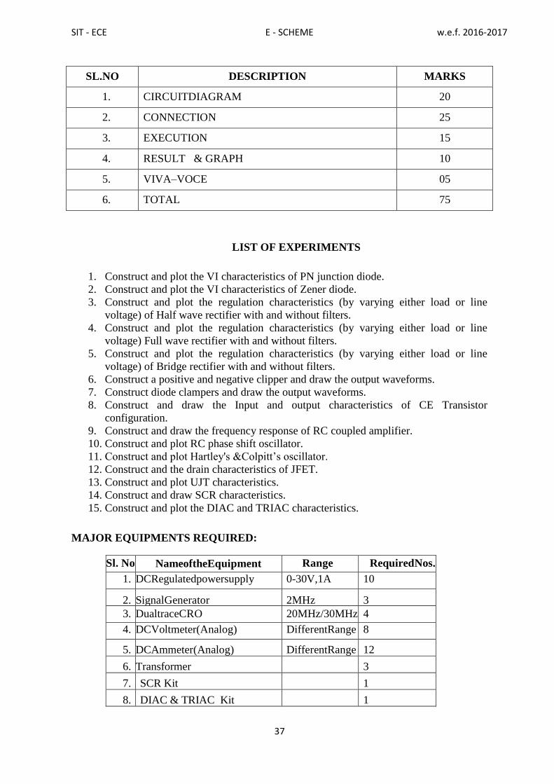
SL.NO DESCRIPTION MARKS
1. CIRCUITDIAGRAM 20
2. CONNECTION 25
3. EXECUTION 15
4. RESULT & GRAPH 10
5. VIVA–VOCE 05
6. TOTAL 75
LIST OF EXPERIMENTS
1. Construct and plot the VI characteristics of PN junction diode.
2. Construct and plot the VI characteristics of Zener diode.
3. Construct and plot the regulation characteristics (by varying either load or line
voltage) of Half wave rectifier with and without filters.
4. Construct and plot the regulation characteristics (by varying either load or line
voltage) Full wave rectifier with and without filters.
5. Construct and plot the regulation characteristics (by varying either load or line
voltage) of Bridge rectifier with and without filters.
6. Construct a positive and negative clipper and draw the output waveforms.
7. Construct diode clampers and draw the output waveforms.
8. Construct and draw the Input and output characteristics of CE Transistor
configuration.
9. Construct and draw the frequency response of RC coupled amplifier.
10. Construct and plot RC phase shift oscillator.
11. Construct and plot Hartley's &Colpitt‟s oscillator.
12. Construct and the drain characteristics of JFET.
13. Construct and plot UJT characteristics.
14. Construct and draw SCR characteristics.
15. Construct and plot the DIAC and TRIAC characteristics.
MAJOR EQUIPMENTS REQUIRED:
Sl. No NameoftheEquipment Range RequiredNos.
1. DCRegulatedpowersupply 0-30V,1A 10
2. SignalGenerator 2MHz 3
3. DualtraceCRO 20MHz/30MHz 4
4. DCVoltmeter(Analog) DifferentRange 8
5. DCAmmeter(Analog) DifferentRange 12
6. Transformer 3
7. SCR Kit 1
8. DIAC & TRIAC Kit 1
SIT - ECE E - SCHEME w.e.f. 2016-2017
38
9. RC Phase shift oscillator Kit 1
10. Hartely&Colpitt‟s oscillator Kit 1
11. RC Coupled amplifier Kit 1
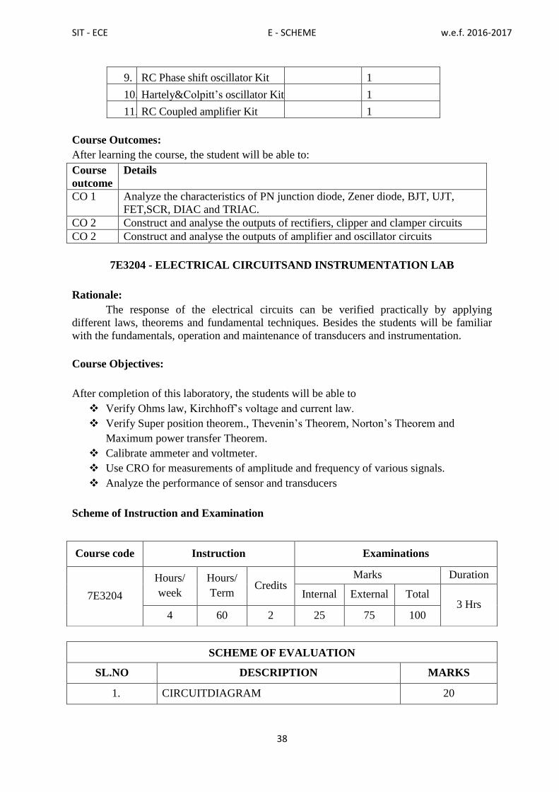
Course Outcomes:
After learning the course, the student will be able to:
Course
outcome
Details
CO 1 Analyze the characteristics of PN junction diode, Zener diode, BJT, UJT,
FET,SCR, DIAC and TRIAC.
CO 2 Construct and analyse the outputs of rectifiers, clipper and clamper circuits
CO 2 Construct and analyse the outputs of amplifier and oscillator circuits
7E3204 - ELECTRICAL CIRCUITSAND INSTRUMENTATION LAB
Rationale:
The response of the electrical circuits can be verified practically by applying
different laws, theorems and fundamental techniques. Besides the students will be familiar
with the fundamentals, operation and maintenance of transducers and instrumentation.
Course Objectives:
After completion of this laboratory, the students will be able to
Verify Ohms law, Kirchhoff‟s voltage and current law.
Verify Super position theorem., Thevenin‟s Theorem, Norton‟s Theorem and
Maximum power transfer Theorem.
Calibrate ammeter and voltmeter.
Use CRO for measurements of amplitude and frequency of various signals.
Analyze the performance of sensor and transducers
Scheme of Instruction and Examination
SCHEME OF EVALUATION
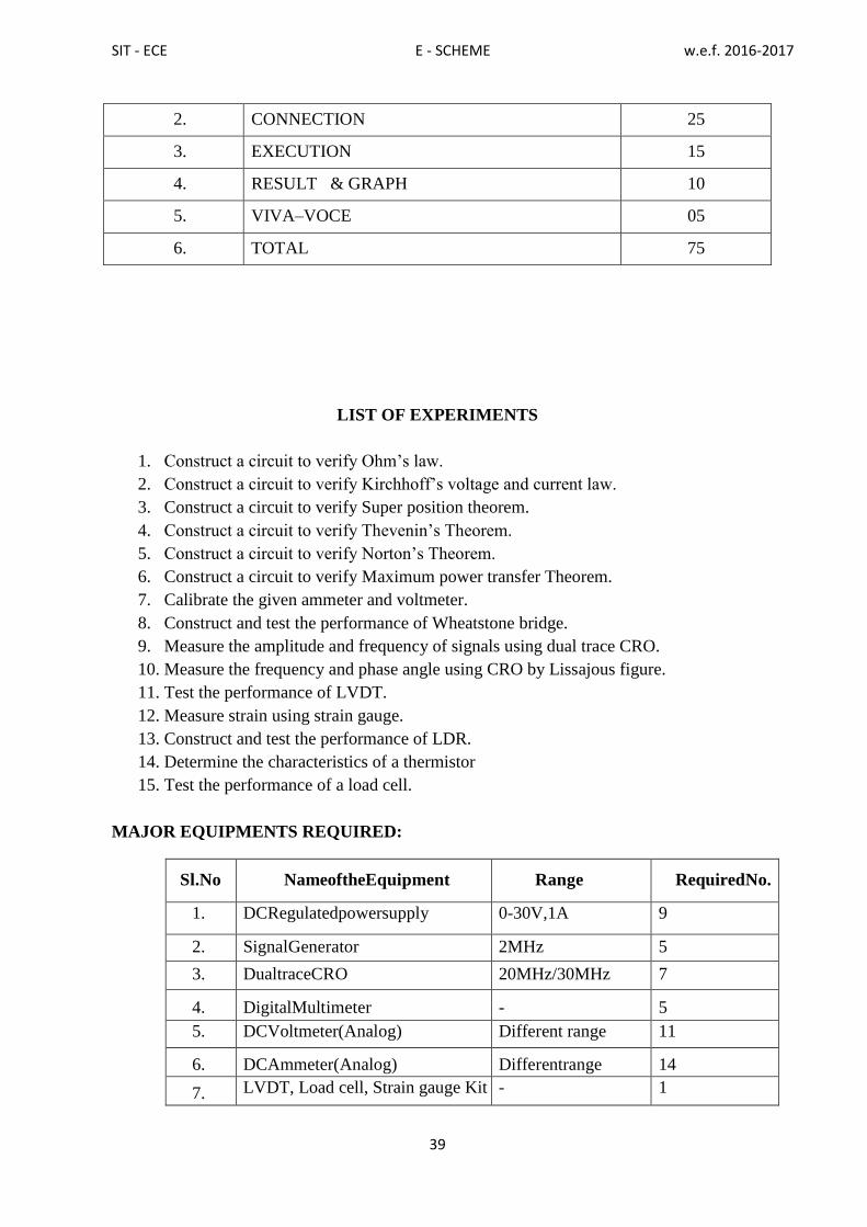
SL.NO DESCRIPTION MARKS
1. CIRCUITDIAGRAM 20
Course code Instruction Examinations
7E3204
Hours/
week
Hours/
Term Credits
Marks Duration
Internal External Total 3 Hrs
4 60 2 25 75 100
SIT - ECE E - SCHEME w.e.f. 2016-2017
39
2. CONNECTION 25
3. EXECUTION 15
4. RESULT & GRAPH 10
5. VIVA–VOCE 05
6. TOTAL 75
LIST OF EXPERIMENTS
1. Construct a circuit to verify Ohm‟s law.
2. Construct a circuit to verify Kirchhoff‟s voltage and current law.
3. Construct a circuit to verify Super position theorem.
4. Construct a circuit to verify Thevenin‟s Theorem.
5. Construct a circuit to verify Norton‟s Theorem.
6. Construct a circuit to verify Maximum power transfer Theorem.
7. Calibrate the given ammeter and voltmeter.
8. Construct and test the performance of Wheatstone bridge.
9. Measure the amplitude and frequency of signals using dual trace CRO.
10. Measure the frequency and phase angle using CRO by Lissajous figure.
11. Test the performance of LVDT.
12. Measure strain using strain gauge.
13. Construct and test the performance of LDR.
14. Determine the characteristics of a thermistor
15. Test the performance of a load cell.
MAJOR EQUIPMENTS REQUIRED:
Sl.No NameoftheEquipment Range RequiredNo.
1. DCRegulatedpowersupply 0-30V,1A 9
2. SignalGenerator 2MHz 5
3. DualtraceCRO 20MHz/30MHz 7
4. DigitalMultimeter - 5
5. DCVoltmeter(Analog) Different range 11
6. DCAmmeter(Analog) Differentrange 14
7. LVDT, Load cell, Strain gauge Kit - 1

SIT - ECE E - SCHEME w.e.f. 2016-2017
40
Course Outcomes:
After learning the course, the student will be able to:
Course
outcome
Details
CO1 Analyze and verify Ohms Law, KVL, KCL, Superposition, Thevenin, Norton
and
Maximum power transfer.
CO2 Calibrate ammeter and voltmeter.
CO3 Measure various signals amplitude and frequency.
CO4 Analyze the performance of wheatstone bridge, LDR, LVDT, strain gauge,
thermistor and Load cell
7E3402 - PROGRAMMING IN C LAB
Rationale:
This course is a fundamental for the student to learn how to write a program in high level
language, so it will be useful for Electronics and Communication Engineers to write coding
and to develop the software. Further practice for writing simple program for Electronics
application is insisted.
Course Objectives:
Attheendofthecourse,thestudentswillbeableto
Analyzethegivenproblem.
Thinkthelogictosolvethegivenproblem.
Describetheconceptsofconstants,variables,datatypesandoperators.
Developprogramsusinginputandoutputoperations.
Writeprogramsusingdifferentloopingandbranchingstatements.
Writeprogramsbasedonarrays.
Writeprogramsforsolvingsimpleequationsusedincircuittheory.
Scheme of Instruction and Examination
Course code Instruction Examinations
7E3402
Hours/ week Hours/
Term Credits
Marks Duration
Internal External Total
3 Hrs Tutorial practical 75 3 25 75 100 1 4

SIT - ECE E - SCHEME w.e.f. 2016-2017
41
SCHEME OF EVALUATION
No. Allocation Marks
1 Algorithm 10
2 Program 30
3 Execution 25
3 Result 05
4 VivaVoce 05
Total 75
LIST OF EXPERIMENTS
1. Write C language program to find the solution of a quadratic equation.
2. Write C language program to find whether the given number is a positive number,
negative number or zero.
3. Write C language program to find the sum of series using While loop.
4. Write C language program to perform the Arithmetic operation based on the numeric
keypressusingswitchcasestatement. (1-Addition,2-Subtraction,3–multiplication,4 -
Division).
5. Write C language program to find factorial of given N numbers using function.
6. Write C language program to prepare the total marks for N students by reading the
Name, Reg. No, Marks1to Marks6usingarrayofstructure.
7. Write C language program to swap the values of two variables.
8. Write C language program to implement Ohms Law
9. WriteClanguageprogramtocalculatetheequivalentresistanceofthreeresistances
connected in series and parallel.
10. WriteClanguageprogramtocalculatetheequivalentCapacitanceofthreeCapacitors
connected in series and parallel.
11. WriteClanguageprogramtofindResonantFrequencyofRLCSeriesandParallel Circuits.
12. Write C language program to find the power factor of series RL circuits.
13. Write C language program to find the Q factor for series resonant circuits.
14. WriteClanguageprogramtofindtheQfactorforparallelresonantcircuits.
15. Write C languageprogram to find the single-Phase power
16. Analyze the C program to identify the errors.
HARDWAREREQUIRMENT:
Desktop/laptopcomputers: 15nos
Laserprinter : 01no
SOFTWAREREQUIREMENT:

SIT - ECE E - SCHEME w.e.f. 2016-2017
42
C-compilerandeditor
Course Outcomes:
After learning the course, the student will be able to:
Course
outcome
Details
CO1 Analyse the problemsolving
CO2 Know the concept of constants, variables, data types and operators.
CO3 Write programs in C language using loop, branch and array.
CO4 Write C programs forsimple equations used in circuit theory
7E3403 - COMPUTER APPLICATION LAB FOR ELECTRONICS
Rationale:
The Computer Application lab in Electronics facilitates the necessary knowledge and
skills regarding creating, working and maintaining the documents, analyzing the data with
charts manipulation of databases, presentation of documents with audio visual effects in a
computer and provides the latest tools and technologies in helping the students to fetch
better employment.
Course Objectives:
At the end of the course, the students will be able to
Understand operating systems
Create documents in Microsoft Word.
Creating spreadsheets in Microsoft Excel.
Create Power Point Presentation
Simulate and test the characteristics of diode, transistor etc
Scheme of Instruction and Examination
SCHEME OF EVALUATION
CONTENT Max. Marks
Course code Instruction Examinations
7E3403
Hours/ week Hours/
Term Credits
Marks Duration
Internal External Total
3 Hrs Tutorial practical 75 3 25 75 100
1 4

SIT - ECE E - SCHEME w.e.f. 2016-2017
43
Section I Section II
Procedure 15 15
Execution 15 15
Result with printout 5 5
Viva 5
Total 75
LIST OF EXPERIMENTS
Section I
1. WINDOWS:
Basic
• Turning on the computer and logging on.
• The Windows screen.
• Running programs from the Start Menu.
• Minimizing, maximizing, moving, resizing and closing windows.
• Logging off and shutting down your computer.
• Running multiple programs.
• Desktop icons and creating a desktop shortcut.
• Managing programs from the taskbar.
• Closing programs
• Managing Windows Explorer.
• Understanding file extensions
• Viewing storage devices and network connections.
• Managing USB flash drives
Exercise in WINDOWS:
a. Install screen saver and change the monitor resolution by 1280X960
b. Setting wall papers
c. Creating, moving, deleting and renaming a folder
d. Copying files into CD/DVD
e. Recording and saving an audio file
f. Set/Change the date and time.
2. WORD PROCESSING
Basic
• Creating documents in Microsoft Word.
• Typing text, numbers and dates into a document.

SIT - ECE E - SCHEME w.e.f. 2016-2017
44
• Easy formatting.
• Checking the spelling in your document.
• Making and saving changes to your document.
Exercise in WORD PROCESSING:
Create a standard covering letter and use mail merge to generate the customized letters for
applying to a job in various organizations. Also, create a database and generate labels for the
applying organizations.
3. Create a newsletter of three pages with two columns text. The first page contains some
formatting bullets and numbers. Set the document background color and add „confidential‟
as the watermark. Give the document a title which should be displayed in the header. The
header/ footer of the first page should be different from other two pages. Also, add author
name and date/ time in the header. The footer should have the page number.
4. SPREADSHEET
Basic
• Understanding spreadsheet functionality.
• Creating spreadsheets in Microsoft Excel.
• Typing text numbers and dates into a worksheet.
• Easy formulas.
• Easy formatting.
• Making and saving changes to your workbook.
• Printing a worksheet
Exercises in SPREADSHEET
Create a table of records with columns as Name and Donation Amount. Donation
amount should be formatted with two decimal places. There should be at least twenty
records in the table. Create a conditional format to highlight the highest donation with
blue color and lowest donation with red color. The table should have a heading.
5. Prepare line, bar and pie chart to illustrate the subject wise performance of the class for
any one semester
6. Exercise in DATABASE
Prepare a payroll for employee database of an organization with the following details:
Employee Id, Employee name, Date of Birth, Department and Designation, Date of
appointment, Basic pay, Dearness Allowance, House Rent Allowance and other
deductions if any.
Perform simple queries for different categories.
7.Exercise in POWER POINT
Create a Presentation on a mini project with ten different slide transitions with sound effect.
Accessing the Internet
• Going to a specific website and bookmarking.
• Understanding how to search/Google effectively.
• Copy and paste Internet content into your documents and emails.
• Stopping and refreshing pages.
• Understanding social media platforms such as Face book and Twitter.

SIT - ECE E - SCHEME w.e.f. 2016-2017
45
8.Exercise in INTERNET
a. Create e-mail id
b. Send the e-mail to at least 2 of your friends.
c. Create Google forms
Section II
9. Simulate VI characteristics of PN junction diode.
10. Simulate VI characteristics of LED.
11. Simulate VI characteristics of Zener diode.
12. Simulate VI characteristics of NPN transistor.
13. Simulate VI characteristics of FET.
14. Simulate VI characteristics of UJT.
15. Simulate VI characteristics of SCR.
SOFTWARE REQUIREMENTS
SECTION I
Operating System: Windows XP or Windows Vista or Windows 7 / Linux
Office Package: Microsoft office 2000 or Office 2003 or Office 2007/Open Office
SECTION II
SPICE simulation tools: PSPICE or Multisim or Lab VIEW / OrCAD / TINA
HARDWARE REQUIREMENTS
Desktop/Laptop Computer System: 15 Nos
Laser Printer: 1 No
Course Outcomes:
After learning the course, the student will be able to:
Course
outcome
Details
CO1 Create documents and spread sheets
CO2 Prepare power point presentation
CO3 Analyze the characteristics of diode and transistor using simulation

SIT - ECE E - SCHEME w.e.f. 2016-2017
46
IV - TERM

SIT - ECE E - SCHEME w.e.f. 2016-2017
47
7E4301 - ELECTRONIC CIRCUITS
Rationale:
After obtaining the basic knowledge of electronic devices like diodes, transistors, and
elementary circuits, this course will enable the students to learn about the different types of
biasing and bias stability, the use of transistors in analog circuits like power amplifier, FET
amplifiers, feedback amplifier, oscillators, and wave shaping circuits and in multivibrators,
power supplies and voltage regulators. ICs and their applications for effective functioning in
the field of electronic service industry.
Course Objectives:
At the end of the course, the students will be able to
Understand the concept of load line, different types of biasing, bias stability and
compensation.
Understand BJT amplifiers, Emitter followers & Darlington Configuration
Analyze the frequency response characteristics of amplifiers
Differentiate between Class A, Class B, and Class C amplifiers
Understand FET amplifiers, Biasing & Feedback Amplifiers.
Understand the types of oscillators and method of waveform generation
Construct regulated power supplies and the ICs available
Voltage regulator circuits and its working principle
SMPS block diagram and its working principle
Scheme of Instruction and Examination
Course code Instruction Examinations
7E4301
Hours/
week
Hours/
Term Credits
Marks Duration
Internal External Total 3 Hrs
5 75 5 25 75 100
UNITS - ALLOCATION OF HOURS AND MARKS
Unit no. Topics Hours Marks
I Transistor Biasing and Small Signal Amplifiers 13 15
II Feedback & Power Amplifiers 13 15
III FET Amplifiers & Its Biasing Methods: 13 15
IV Oscillators and Wave Shaping Circuits 13 15
V Voltage Regulators 13 15
Cycle Tests, Model Exam& Revision classes
(2+2+3+3) 10
-
Total 75 75

SIT - ECE E - SCHEME w.e.f. 2016-2017
48
7E4301 - ELECTRONIC CIRCUITS
CONTENT DETAILS
Unit-1 Transistor biasing and small signal amplifiers
1.1 Transistor CE amplifier, DC and A.C load lines, operating point, stabilization, stability
factor, proper biasing, types of biasing- collector to base biasing, potential divider
biasing, transistor
1.2 CE amplifier, Classification of amplifiers, need of multi stage amplifier, working and
frequency response of two-stage RC coupled amplifier, transformer coupled amplifier,
direct coupled amplifier, emitter follower, Darlington pair.
Unit-2 Feedback & Power amplifiers
2.1 Principle of negative and positive feedback. Feedback amplifiers- block diagram, types,
expression for gain, effects on gain, bandwidth, input and output impedances,
advantages.
2.2 Power amplifier - classification amplifier. class – A, push-pull, complementary push-
pull amplifiers. Applications of power amplifiers. Heat sink.
2.3Tuned power amplifier - single and double tuned, class C tuned amplifiers.
Unit-3 FET Amplifiers & its biasing methods:
3.1 Biasing of FET‟s: Self bias, Voltage divider bias, Source bias, Current source bias
3.2 Biasing of MOSFETS: Zero bias for DMOSFET, Drain feedback bias for EMOSFET
3.3 FET Amplifiers: Common source, common drain and Common gate amplifiers (No
derivations) - DC amplifier using FET chopper-Differential Amplifier.
Unit-4 Oscillators and Wave shaping circuits
4.1 Oscillators - Conditions for Oscillation - Principle of tank circuit - LC Oscillator - Tuned
Collector Oscillator - Clapp‟s Oscillators - Wien bridge Oscillator
4.2 Negative resistance Oscillator - Arm strong oscillator – Miller crystal oscillator – Pierce
crystal oscillator.
Unit-5 Voltage Regulators
5.1Types of voltage regulators: Shunt voltage regulator - Series voltage regulator Zener
Diode regulator
5.2Transistor Shunt regulator - Emitter follower series voltage regulator-Transistorized
series feedback type regulator – Transistor series regulator with Darlington pair.
5.3 IC regulators 78XX and 79XX – Regulated power supply block diagram and Need of
DC power supply Block diagram of SMPS – SMPS working principle

SIT - ECE E - SCHEME w.e.f. 2016-2017
49
Textbook
Sl.No. Name of the Book Author Publisher
1
Electronic Devices and
Circuits
G.K.Mithal Khanna Publishers23rd
edition 2014
Reference books
S.No Title Author Publisher
1. Electronics Devices & Circuits
Salivahanan S,
N.Suresh Kumar
Mcgraw Hill Education
3rd
edition, 2012
2. Electronic Principles Albert Malvino
David J.Bates
Tata Mc.Graw Hill Co.
Limited. 7th
edition
2008
3. Electronic Devices and Circuits Jacob Millman and
C.Halkies
Tata Mc.Graw Hill Co.
Limited. Reprint 2008
4. Pulse, Digital and Switching
Waveforms –
Jacob Millman,Herbert
Taub and Suryaprakash
Rao Mothiki
Tata Mc.Graw Hill Co.
Limited, First reprint
2011.
Online Resources
http://freevideolectures.com/Course/2261/Basic-Electronics-and-Lab/2
http://www.vidyarthiplus.in/2011/11/electronic-device-and-circuits-edc.html
Course Outcomes:
After learning the course, the student will be able to:
CO1 Explain about Transistor biasing and signal amplifiers
CO2 Explain about Feedback and power amplifiers
CO3 Explain about FET amplifiers and its biasing methods
CO4 Explain about Oscillator and wave shaping circuits
CO5 Explain about voltage regulator and its different types

SIT - ECE E - SCHEME w.e.f. 2016-2017
50
7E4205 - COMMUNICATION ENGINEERING
Rationale:
Today communication engineering has developed to a great extent that there is
always the need for study of various communication concepts. This course fulfills the need
for students to have a thorough knowledge of various types of networks, transmission lines,
modulation, audio systems and video systems.
Course Objectives:
At the end of the course, the students will be able to
Understand the basic terms related to communication
Understand the theory of Propagation
Understand the principles of working of antennas
Understand the concept of modulation
Study Amplitude Modulation Process
Learn about different types of AM Transmitter & receiver
Study the Frequency Modulation Process
Learn about different types of FM Transmitters & Receivers
Understand the concept Phase Modulation and Pulse Modulation
Understand the theory of Transmission lines
Understand the theory of various networks Propagation
Learn Different types of Microphones and Loudspeakers
Understand the principles of Monochrome CCTV and Cable TV
Scheme of Instruction and Examination
Course code Instruction Examinations
7E4205
Hours/
week
Hours/
Term Credits
Marks Duration
Internal External Total 3 Hrs
5 75 5 25 75 100
UNITS - ALLOCATION OF HOURS AND MARKS
Unit no. Topics Hours Marks
I Basics of Communication 10 15
II Amplitude Modulation 13 15
III Frequency Modulation and Pulse Modulation 13 15
IV Transmission Lines and Networks 15 15
V Audio and Video Systems 14 15
Cycle Tests, Model Exam& Revision classes
(2+2+3+3) 10
Total 75 75
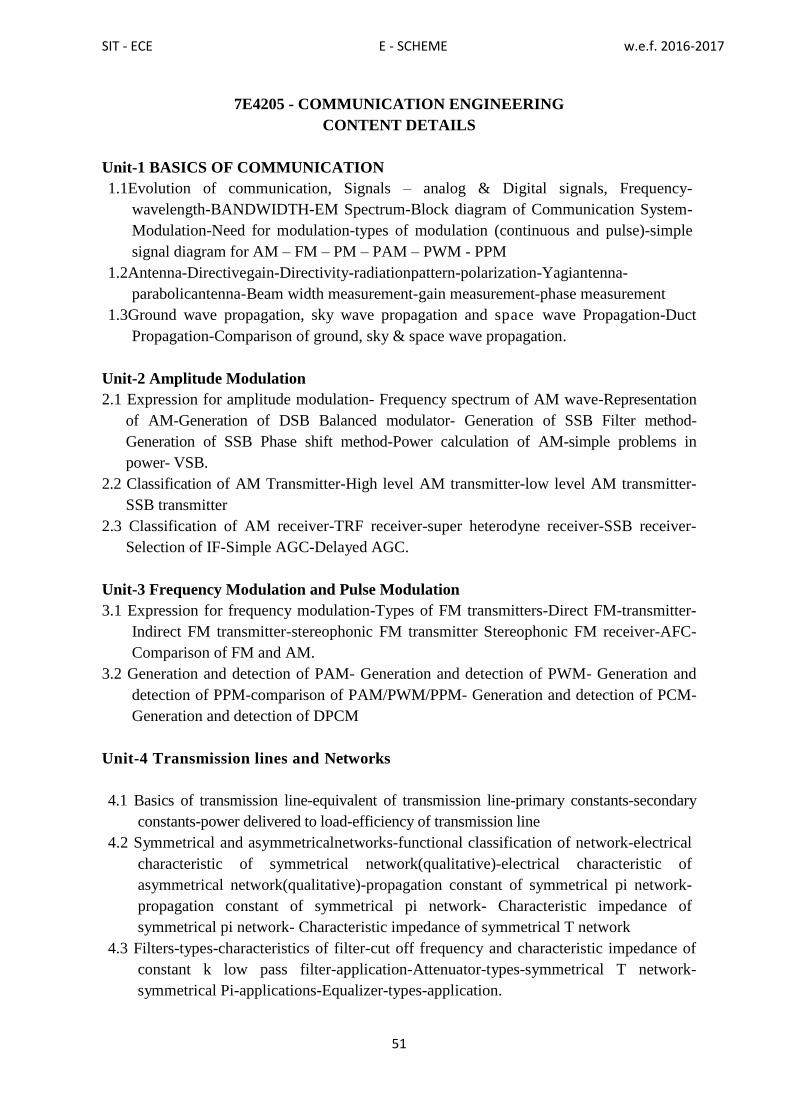
SIT - ECE E - SCHEME w.e.f. 2016-2017
51
7E4205 - COMMUNICATION ENGINEERING
CONTENT DETAILS
Unit-1 BASICS OF COMMUNICATION
1.1Evolution of communication, Signals – analog & Digital signals, Frequency-
wavelength-BANDWIDTH-EM Spectrum-Block diagram of Communication System-
Modulation-Need for modulation-types of modulation (continuous and pulse)-simple
signal diagram for AM – FM – PM – PAM – PWM - PPM
1.2Antenna-Directivegain-Directivity-radiationpattern-polarization-Yagiantenna-
parabolicantenna-Beam width measurement-gain measurement-phase measurement
1.3Ground wave propagation, sky wave propagation and space wave Propagation-Duct
Propagation-Comparison of ground, sky & space wave propagation.
Unit-2 Amplitude Modulation
2.1 Expression for amplitude modulation- Frequency spectrum of AM wave-Representation
of AM-Generation of DSB Balanced modulator- Generation of SSB Filter method-
Generation of SSB Phase shift method-Power calculation of AM-simple problems in
power- VSB.
2.2 Classification of AM Transmitter-High level AM transmitter-low level AM transmitter-
SSB transmitter
2.3 Classification of AM receiver-TRF receiver-super heterodyne receiver-SSB receiver-
Selection of IF-Simple AGC-Delayed AGC.
Unit-3 Frequency Modulation and Pulse Modulation
3.1 Expression for frequency modulation-Types of FM transmitters-Direct FM-transmitter-
Indirect FM transmitter-stereophonic FM transmitter Stereophonic FM receiver-AFC-
Comparison of FM and AM.
3.2 Generation and detection of PAM- Generation and detection of PWM- Generation and
detection of PPM-comparison of PAM/PWM/PPM- Generation and detection of PCM-
Generation and detection of DPCM
Unit-4 Transmission lines and Networks
4.1 Basics of transmission line-equivalent of transmission line-primary constants-secondary
constants-power delivered to load-efficiency of transmission line
4.2 Symmetrical and asymmetricalnetworks-functional classification of network-electrical
characteristic of symmetrical network(qualitative)-electrical characteristic of
asymmetrical network(qualitative)-propagation constant of symmetrical pi network-
propagation constant of symmetrical pi network- Characteristic impedance of
symmetrical pi network- Characteristic impedance of symmetrical T network
4.3 Filters-types-characteristics of filter-cut off frequency and characteristic impedance of
constant k low pass filter-application-Attenuator-types-symmetrical T network-
symmetrical Pi-applications-Equalizer-types-application.

SIT - ECE E - SCHEME w.e.f. 2016-2017
52
Unit-5 Audio and Video systems
5.1Microphone-characteristics-classification-carbonmicrophone-condenser
microphone-piezo electric micro phone-moving coil microphone and velocity ribbon.
5.2 Loud Speakers-Characteristics-Dynamic Cone-Horn-Electro static-woofer-
midrange-tweeter-cross over network-DVD system-DTS – MP3
5.3TVScanning-synchronization-aspectratio-compositevideosignal-TVtransmitter-
TVreceiver-CCTV-Cable TV
Textbook
Sl.No. Name of the Book Author Publisher
1
Electronic Communication
Systems Kennedy Davis
TATA McGRAW-
HILL
4th
edition 2008
Reference Books:
S.No Title Author Publisher
1 Electronic Communication
Systems Kennedy Davis
TATAMcGRAW-
HILL 4th
edition 2008
2 Antenna and Wave
Propagation
John D Kraus,Ronald J
Marhefka,Ahmad S Khan
TATA McGRAW-
HILL4th
edition 2010
3
Antenna and Wave
Propagation K.D. Prasad
Sathya Pragashan
3rd
reprint 1996
4
Transmission lines and
Networks Umesh Sinha
Sathya Pragashan
New Delhi
Online Resources:
http://nptel.ac.in/courses/117102059/
https://lecturenotes.in/subject/50/communication-engineering
http://www.nptelvideos.in/2012/11/communication-engineering.html
https://www.youtube.com/playlist?list=PL7748E9BEC4ED83CA
Course Outcomes:
After learning the course, the student will be able to:
CO1 Understand the basic concepts of modulation, propagation, antenna
CO2 Explain amplitude modulation, AM transmission & Reception
CO3 Explain frequency modulation, FM transmission& Reception
CO4 Understand the concept of transmission lines and networks
CO5 Brief working principles of audio & video systems

SIT - ECE E - SCHEME w.e.f. 2016-2017
53
7E4206 –DIGITALELECTRONICS
Rationale:
This course enables the students to know the basic concepts of digital electronics and
gain familiarity with the available IC chips. The students will learn about number systems,
logic gates, various codes, parities, Boolean algebra, decoder, encoder, multiplexer and
demultiplexer, flip-flop, counters, shift registers, ADC, DAC, Logic families , memories
This will form a broad base for studying digital system design, advanced microprocessors
and further studies
Course Objectives:
At the end of the course, the students will be able to
Understand various Number System, basic Boolean postulates & laws and De-
Morgan‟s theorem
Understand the concept of Karnaugh Map.
Learn about logic Gates.
Learn the different digital logic families
Learn arithmetic circuits-adder/subtractor, BCD adder.
Understand the encoder/decoder & MUX / DEMUX
Understand the concept of parity Generator, and checkers
Understand various types of flip-flops, counters and shift registers
Understand the concept of RAM & ROM and its types
Understand the different types of ADC & DAC
Understand the internal architecture& instruction set of 8085 Microprocessor.
Scheme of Instruction and Examination
Course code Instruction Examinations
7E4206
Hours/
week
Hours/
Term Credits
Marks Duration
Internal External Total 3 Hrs
5 75 5 25 75 100
UNITS - ALLOCATION OF HOURS AND MARKS
Unit no. Topics Hours Marks
I NumberSystem andBooleanAlgebra 13 15
II CombinationalCircuits 13 15
III SequentialCircuits 13 15
IV MemoryDevices andConverters 13 15
V Microprocessor 8085 13 15
Cycle Tests, Model Exam and Revision classes
(2+2+3+3) 10
-
Total 75 75

SIT - ECE E - SCHEME w.e.f. 2016-2017
54
7E4206 –DIGITALELECTRONICS
CONTENT DETAILS
Unit-1 NUMBER SYSTEM AND BOOLEAN ALGEBRA:
1.1 Basic difference between analog and digital signal. Binary, Octal, Decimal,
Hexadecimal - Conversion from one to another. Binary codes – BCD code,
Alpha numeric codes: ASCII and EBCDIC.
1.2 Boolean Algebra- Boolean postulates and laws- De-Morgan‟s theorem Simplification
of Boolean expressions using Karnaugh map (up to 4 variables-pairs, quad, octets)-
Don‟t care conditions and constructing the logic circuits for the Boolean expressions.
1.3LOGIC GATES: Gates – AND, OR, NOT, NAND, NOR, EX-OR, EX-NOR -
Implementation of logic functions using gates - Realization of gates using universal
gates Simplification of expression using Boolean techniques- Boolean expression for
outputs.
1.4 Digital logic families –Fan in , Fan out, Propagation delay - TTL,CMOS Logics and
their characteristics - comparison and applications -Tristate logic.
Unit-2 COMBINATIONAL CIRCUITS :
2.1 Arithmetic circuits - Binary – Addition, subtraction, 1‟s and 2‟s complement -
Signed binary numbers- Half Adder- Full Adder- Half Subtractor - Full Subtractor-
Parallel and serial Adders- BCD adder.
2.2 Encoder and decoder – 3 to 8 decoder, Multiplexer- basic 2 to 1 MUX, 4 to 1 MUX,
8 to 1 MUX - applications of the MUX – Demultiplexer - 1 to 2 demultiplexer, 1 to
4 demultiplexer, 1 to 8 demultiplexer
2.3 Parity Checker and generator. Four bit decoder (BCD) circuits for 7 segment
display/ driver ICs
Unit-3 SEQUENTIAL CIRCUITS:
3.1 FLIP FLOPS – SR, JK, T, D FF, JK- MS FF - Triggering of FF – edge & level,
3.2 Counters – 4 bit Up - Down Asynchronous / ripple counter - Decade counter- Mod 3,
Mod 7 counter. 4 bit Synchronous Up - Down counter - Johnson counter, Ring
counter
3.3 REGISTERS- 4-bit shift register- Serial IN Serial OUT- Serial IN Parallel OUT -
Parallel IN Serial OUT- Parallel IN Parallel OUT.
Unit-4 MEMORY DEVICES AND CONVERTERS
4.1 Classification of memories - RAM organization - Address Lines and Memory Size-
Read /write operations- Static RAM - Bipolar RAM cell-Dynamic RAM- SD
RAM- DDR RAM. Read only memory – ROM organization- Expanding memory-
PROM, EPROM- and EEPROM
4.2 Digital to Analog converter: binary weighted, R-2R ladder network
4.3 Analog to Digital converter: Successive approximation, Ramp, dual slope type

SIT - ECE E - SCHEME w.e.f. 2016-2017
55
Unit-5 MICROPROCESSOR – 8085
5.1Evolution of microprocessor -Microprocessor based system -Glossary of terms related
to microprocessor (ALU, ALE, BUS, Address bus, Data bus, Control bus, Bit, Byte,
Nibble, Instruction, Program, Memory, ROM, RAM, Mnemonic, Assembly language,
Assembler, Latch, CPU, Interrupt, Subroutine). – Architecture of 8085 microprocessor-
Address bus-Multiplexed address data bus –de multiplexing the address and data bus –
5.2 Instructions MOV, ADD, SUB- Addressing modes – Machine cycle – Opcode fetch -
memory read- memory write- I/O read, I/O write - Instruction cycle (Timing diagram)
for MOV r1, r2 instruction. Interrupts (types & Priorities)
Text book:
S.No Title Author Publisher
1 A Text book of Digital Electronics R.S.Sedha S.Chand& Co5th
edition 2013
2 Digital Fundamentals T.L.Floyd Pearson India 10th
edition 2011
Reference Books:
S.No Title Author Publisher
1. Digital design principles and
applications
D.P.Leach,
A.P.Malvino, G.Saha
Tata Mc Graw Hill
6th edition 2006
2. Modern digital Electronics R. P. Jain Tata Mc Graw Hill
3. Digital design M. Morris R. Mano
Michael D. Ciletti
Pearson,
5th edition 2013.
4. Digital systems R.J.Tocci,
S.Widemer,G.L.Mos
Pearson
9th edition 2007
5. 2000 solved problems in digital
electronics
S.P.Bali Tata Mc Graw Hill
Online Resources:
http://web.iitd.ac.in/~shouri/eel201/lectures.php
https://lecturenotes.in/subject/14/digital-electronics-circuit
Course Outcomes:
After learning the course, the student will be able to:
CO1 Explain about Number system, Boolean algebra, Logic gates and digital logic
families
CO2 Explain about Combinational circuits – Full adder & Full subtractor.MUX and
DEMUX, BCD Adder etc.
CO3 Explain about Sequential circuits – Flip-flops, Counters and shift registers
CO4 Explain about Memory devices – RAM & ROM organizations, ADC & DAC.
CO5 Explain about Microprocessor 8085 – Evolution, Instructions set, Addressing modes
and interrupts.

SIT - ECE E - SCHEME w.e.f. 2016-2017
56
7E4302 - LINEAR INTEGRATED CIRCUITS
Rationale:
LinearIntegratedCircuitsholdsapplicationsinallbranchesofengineering.The
monolithicoperationalamplifierhasbecomeanimportantbuildingblockof linearintegrated
circuitsandapplications. Thiscoursewillimpartindepthknowledgeofoperationalamplifiers,
theirapplicationsandalsoaboutvariousspecialfunctionICsliketimerICandPLL IC‟s , VCO.
Course Objectives:
At the end of the course, the students will be able to
Understand the basic building blocks of linear integrated circuits.
Understand the concept of IC technology and basic terminologies and its types.
Understand the theoretical & circuit aspects of op-amp, which is the backbone for
the basics of linear integrated circuits.
Discuss the op-amp‟s basic construction, characteristics, parameter limitations,
various configurations and countless applications of op-amp.
Analyze and design basic op-amp circuits, particularly various linear and non-
linear circuits, active filters, signal generators
Analyze and design op-amp as oscillators, wave shapers , and converters
Understand the theory and applications of analog multipliers and PLL
Understand a few special function integrated circuits.
Design circuits using operational amplifiers for various applications.
Scheme of Instruction and Examination
Course code Instruction Examinations
7E4302
Hours/
week
Hours/
Term Credits
Marks Duration
Internal External Total 3 Hrs
5 75 5 25 75 100
UNITS - ALLOCATION OF HOURS AND MARKS
Unit no. Topics Hours Marks
I Introduction To Operational Amplifier 13 15
II Linear Application 13 15
III Nonlinear Applications 13 15
IV Timers & Waveform Generators 13 15
V Phase Lock Loop (Pll) & Applications 13 15
Cycle Tests, Model Exam & Revision Classes
(2+2+3+3) 10
-
Total 75 75

SIT - ECE E - SCHEME w.e.f. 2016-2017
57
7E4302 - LINEAR INTEGRATED CIRCUITS
CONTENT DETAILS
Unit-1 Introduction to Operational Amplifier
1.1 Integrated circuit - Classification of IC - Advantages of IC over discrete components –
Types of IC Packages – Operational amplifier IC 741 – Schematic symbol for OPAMP
– pin diagram of IC 741 – Block diagram of an OPAMP – Characteristics of an Ideal
OPAMP Simple Equivalent circuit of an opamp – virtual ground – op-amp parameters
– CMRR –Slew rate.
1.2 Basic linear circuits- Inverting Amplifier, Non Inverting amplifier – Differential
Amplifier – sign changer – scale changer. (Simple problems)
Unit-2 Linear Application
2.1 Summing amplifier - Multiplier – Divider – Voltage follower – comparator – zero
crossing detector - Integrator – Differentiator
2.2 Voltage to current converter – current to voltage converter –Instrumentation amplifier.
2.3 Waveform generators – square wave, triangular wave, sine wave, saw tooth wave
generators. (Qualitative treatment only)
Unit-3 Nonlinear applications
3.1 Schmitt trigger -- Converters -- Voltage to Frequency Conversion -- Frequency to
Voltage Conversion - Sample / Hold circuit – Parameters of sample & hold circuit
3.2 Precision Rectifier -- Oscillators-- Wien Bridge Oscillator -- Phase shift Oscillator --
Relaxation Oscillator -- Logarithmic amplifier and antilogarithmic amplifier
Unit-4 Timers & waveform generators
4.1 Introduction -- functional block diagram of a timer- 555 timer-- operation modes of
555: mono and astable -- Pin configuration of 555.
4.2 555 as wave generators: square wave, Saw tooth wave and Tri-angular Wave 555 dual
timer- Waveform generators – VCO as triangular- square - ramp generator
Unit 5 Phase Lock Loop (PLL) &Applications (Qualitative treatment only)
5.1 PLL – Basic principles of PLL – Basic Block schematic of PLL – Lock range – capture
range - Basic components of PLL – Phase detector- LPF-VCO. Monolithic VCO 566 -
Pin diagram –Basic Block diagram of VCO 566.
5.2 Monolithic PLL 565 - pin diagram - Functional Block diagram of PLL IC 565.
Applications of PLL – frequency translation – frequency multiplication

SIT - ECE E - SCHEME w.e.f. 2016-2017
58
Text Books
Sl.No. Name of the Book Author Publisher
1
OP-AMP and Linear IC‟s RamakantA.Gayakwad
Prentice Hall / Pearson
Education,1994.
2
Integrated Circuits K.R.Botkar Khanna Publishers
3 Linear Integrated Circuits D.Roy Choudhry and
Shail Jain
NewAge International,
2000.
Reference Books :
Sl.No. Name of the Book Author Publisher
1
Design with operational
amplifiers and analog integrated
circuits
Sergio Franco Tata McGraw Hill.
2
Integrated Electronics
Millman.J.and
Halkias.C.C McGraw-Hill, 1972
3 Operational Amplifiers with
Linear Integrated Circuits William D.Stanely
Pearson
Education, 2004
4 Digital Integrated Electronics Taub and Schilling McGraw-Hill, 1997.
5
Applications and Design with
Analog Integrated Circuits Michael Jacob Prentice Hall
Online Resources:
https://www.youtube.com/watch?v=clTA0pONnMs
http://freevideolectures.com/Course/2915/Linear-Integrated-Circuits
Course Outcomes:
On completion of the course the student will be able to:
CO1 Explain about IC technology and basic terminologies and its types and basic OP-
AMP IC
CO2 Explain about various linear applications of OP-AMP IC.
CO3 Explain about various Non - linear applications of OP-AMP IC.
CO4 Explain about Timer 555 IC , applications and monolithic waveform generators.
CO5 Explain about basic concepts of PLL and monolithic technology and its applications

SIT - ECE E - SCHEME w.e.f. 2016-2017
59
7E4303 - COMMUNICATION ENGINEERING AND ELECTRONIC CIRCUITS
SIMULATION LAB
RATIONALE:
Even though the field of electronics and communication engineering changes so fast, the
principles do not change. The lab will make the students to understand and analyze the
operation of electronic circuits. Today, communications is the largest sector of the
electronics field. So the knowledge and understanding of communications is a must for
ECE students
Course Objectives:
At the end of the course, the students will be able to
Verify and analyze the modulated and demodulated output waveforms of AM,
FM,PAM,PWM and PPM.
Understand the functions of LPF and HPF.
Simulate and test Amplifiers, Oscillators and Regulators.
Scheme of Instruction and Examination
SCHEME OF EVALUATION
SL.NO DESCRIPTION MARKS
1 CIRCUIT DIAGRAM 25
2 CONNECTION /
MODEL DEVELOPMENT
20
3 EXECUTION 15
4 RESULT 10
5 VIVA–VOCE 05
TOTAL 75
LIST OF EXPERIMENTS
Course code Instruction Examinations
7E4303
Hours/ week Hours/
Term Credits
Marks Duration
Internal External Total
3 Hrs Tutorial practical 75 3 25 75 100
1 4

SIT - ECE E - SCHEME w.e.f. 2016-2017
60
Communication Engineering
1. Construct and test Amplitude Modulation & Demodulation circuits
2. Construct and test Frequency Modulation & Demodulation
3. Construct and test Pulse Amplitude Modulation & Demodulation
4. Construct and test Pulse Width Modulation & Demodulation
5. Construct and test Pulse Position Modulation & Demodulation
6. Construct and test Low pass Filter
7. Construct and test High pass Filter
Electronic Circuits Simulation
8. Simulate and test the performance of Emitter follower
9. Simulate and test the performance of RC Coupled amplifier
10. Simulate and test the performance of Push pull amplifier
11. Simulate and test the performance of Common source amplifier
12. Simulate and test the performance of Hartley oscillator
13. Simulate and test the performance of RC phase shift oscillator
14. Simulate and test the performance of IC regulators 78XX, 79XX
MAJOR EQUIPMENTS REQUIRED:
S.NO NameoftheEquipment Range RequiredNos.
1. SignalGenerator 2MHz 1
2. DualtraceCRO 20MHz/30MHz 4
3. DigitalMultimeter - 1
4. AM ,FM, PAM, PWM, PPM Kit 1
HARDWAREREQUIREMENT:
DesktopComputers–20Nos
SOFTWAREREQUIREMNT:
Multisim software
Course Outcomes:
On completion of the course the student will be able to:
CO1 Understand the concept of Amplitude, Frequency modulation and demodulation
CO2 Understand the concept of pulse amplitude, width and position modulation and
demodulation
CO3 Understand the function of filters and importance of cutoff frequency
CO4 Simulate and test the performance of amplifier, oscillator and regulator
7E4304 - LINEAR INTEGRATED CIRCUITS & DIGITAL ELECTRONICS LAB
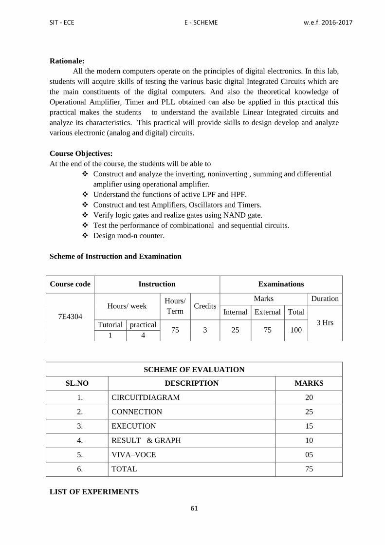
SIT - ECE E - SCHEME w.e.f. 2016-2017
61
Rationale:
All the modern computers operate on the principles of digital electronics. In this lab,
students will acquire skills of testing the various basic digital Integrated Circuits which are
the main constituents of the digital computers. And also the theoretical knowledge of
Operational Amplifier, Timer and PLL obtained can also be applied in this practical this
practical makes the students to understand the available Linear Integrated circuits and
analyze its characteristics. This practical will provide skills to design develop and analyze
various electronic (analog and digital) circuits.
Course Objectives:
At the end of the course, the students will be able to
Construct and analyze the inverting, noninverting , summing and differential
amplifier using operational amplifier.
Understand the functions of active LPF and HPF.
Construct and test Amplifiers, Oscillators and Timers.
Verify logic gates and realize gates using NAND gate.
Test the performance of combinational and sequential circuits.
Design mod-n counter.
Scheme of Instruction and Examination
SCHEME OF EVALUATION
SL.NO DESCRIPTION MARKS
1. CIRCUITDIAGRAM 20
2. CONNECTION 25
3. EXECUTION 15
4. RESULT & GRAPH 10
5. VIVA–VOCE 05
6. TOTAL 75
LIST OF EXPERIMENTS
Course code Instruction Examinations
7E4304
Hours/ week Hours/
Term Credits
Marks Duration
Internal External Total
3 Hrs Tutorial practical 75 3 25 75 100
1 4

SIT - ECE E - SCHEME w.e.f. 2016-2017
62
LINEAR INTEGRATED CIRCUITS
1. Construct and test Inverting – Non inverting amplifier
2. Summer and differential amplifiers.
3. Integrator and Differentiator.
4. Frequency response of Active low pass, high pass filter
5. Schmitt Trigger using op – amp.
6. Phase shift oscillator and Wien bridge oscillator using op –amp.
7. Astable and monostable using NE555 Timer.
DIGITAL ELECTRONICS
8. Verification of Truth table of OR, AND, NOT, NOR NAND and XOR gate.
9. Realization of basic gates using NAND gates.
10. Realization of logic circuit for a given Boolean expression.
11. Construction and verification of truth table Half adder and full adder
12. Construction and verification of truth table for 3:8 Decoder using IC 74138
13. Construction and verification of truth table for 8:1 Multiplexer using IC 74151.
14. Construction and verification of truth table for RS ,JK F/F.
15. Construction and verification of Mod – N counters.
MAJOR EQUIPMENTS REQUIRED:
S.NO NameoftheEquipment Range RequiredNo.
1. DCRegulatedpowersupply 0-30V,1A 10
2. Dual PowerSupply 0-30V,1A 2
3. SignalGenerator 2MHz 5
4. DualtraceCRO 20MHz/30MHz 5
5. DigitalMultimeter - 10
6. IC Trainer kit - 9
Course Outcomes:
On completion of the course the student will be able to:
CO1 Understand the functions of inverting, noninverting , summing and differential
amplifier using operational amplifier.
CO2 Analyze the functions of active LPF and HPF.
CO3 Understand the function of Amplifiers, Oscillators and Timers.
CO4 Test logic gates and realize gates using NAND gate
CO5 Design and test the performance of combinational and sequential circuits.
CO6 Construct and test mod-n counter.
7E4404 - LIFE AND EMPLOYABILITY SKILL LAB

SIT - ECE E - SCHEME w.e.f. 2016-2017
63
RATIONALE: Against the backdrop of the needs of the Industries, as wells as based on fulfilling
the expectations of the Industries, the Diploma Level students have to be trained directly
and indirectly in toning up their competency levels. Proficiency in Communication only,
equips them with confidence and capacity to cope with the employment. Hence, there is a
necessity to focus on these in the curriculum. At the end of the Course, the student is better
equipped to express himself in oral and written communication effectively.
Course Objectives:
At the end of the course, the students will be able to
Emphasize and Enhance Speaking Skills
Increase Ability to Express Views & Opinions
Develop and Enhance Employability Skills
Induce Entrepreneurship and Plan for the Future
Expose & Induce Life Skills for Effective Managerial Ability
Scheme of Instruction and Examination
LIFE AND EMPLOYABILITY SKILLS LAB
CONTENT DETAILS
Sl.
N
o
SECTION SKILLS TO BE
ACQUIRED
ACTIVITY NO. OF
HOUR
S
1.
PART-A
LISTENING ACTIVITY
TOPICS:
1. Global Warming,
2. Pollution,
3. Environment,Communal
Harmony
Deductive/reasoning
skills
Cognitive Skills
Retention Skills
Talking down
notes/hints
Answering
question
Fill in the blanks
the exact words
heard
Brief the read out
passage
04
04
02
02
Course code Instruction Examinations
7E4404
Hours/ week Hours/
Term Credits
Marks Duration
Internal External Total
3 Hrs Tutorial practical 75 3 25 75 100
1 4
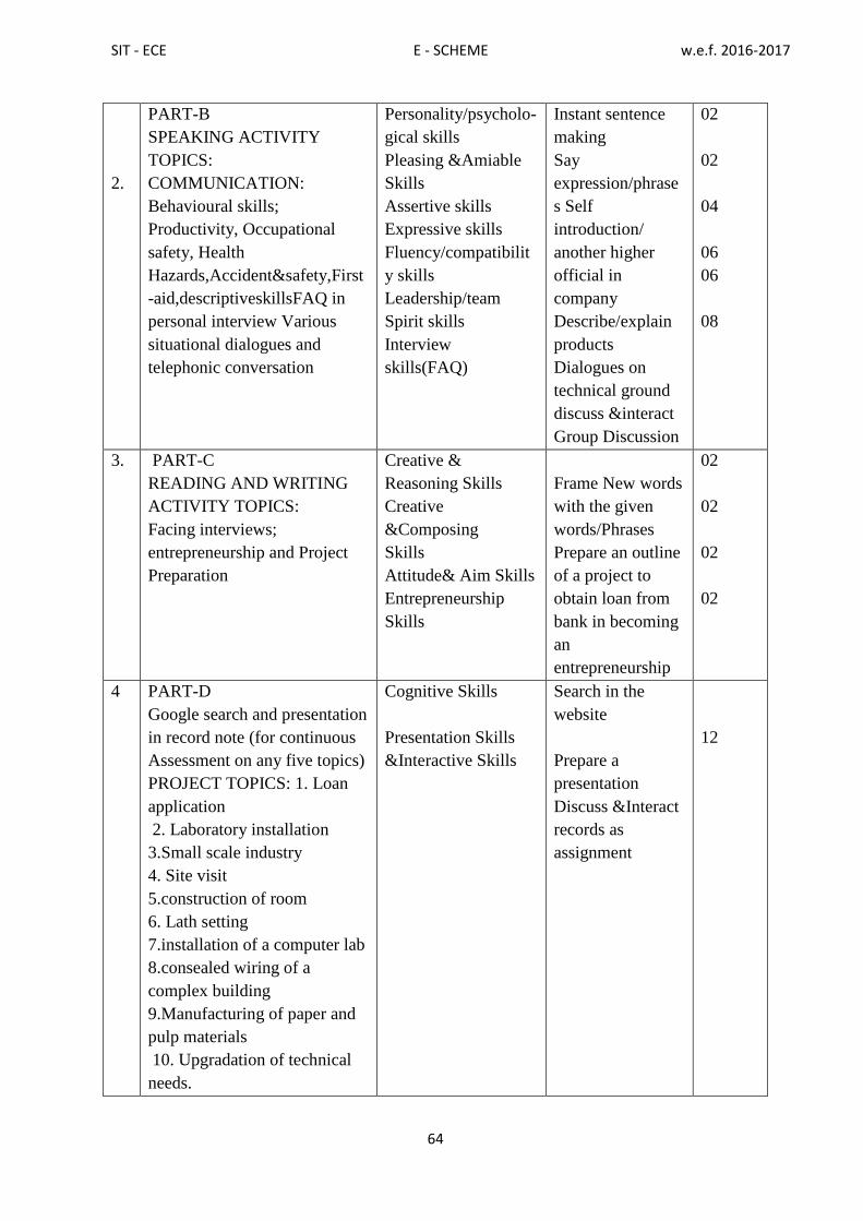
SIT - ECE E - SCHEME w.e.f. 2016-2017
64
2.
PART-B
SPEAKING ACTIVITY
TOPICS:
COMMUNICATION:
Behavioural skills;
Productivity, Occupational
safety, Health
Hazards,Accident&safety,First
-aid,descriptiveskillsFAQ in
personal interview Various
situational dialogues and
telephonic conversation
Personality/psycholo-
gical skills
Pleasing &Amiable
Skills
Assertive skills
Expressive skills
Fluency/compatibilit
y skills
Leadership/team
Spirit skills
Interview
skills(FAQ)
Instant sentence
making
Say
expression/phrase
s Self
introduction/
another higher
official in
company
Describe/explain
products
Dialogues on
technical ground
discuss &interact
Group Discussion
02
02
04
06
06
08
3.
PART-C
READING AND WRITING
ACTIVITY TOPICS:
Facing interviews;
entrepreneurship and Project
Preparation
Creative &
Reasoning Skills
Creative
&Composing
Skills
Attitude& Aim Skills
Entrepreneurship
Skills
Frame New words
with the given
words/Phrases
Prepare an outline
of a project to
obtain loan from
bank in becoming
an
entrepreneurship
02
02
02
02
4 PART-D
Google search and presentation
in record note (for continuous
Assessment on any five topics)
PROJECT TOPICS: 1. Loan
application
2. Laboratory installation
3.Small scale industry
4. Site visit
5.construction of room
6. Lath setting
7.installation of a computer lab
8.consealed wiring of a
complex building
9.Manufacturing of paper and
pulp materials
10. Upgradation of technical
needs.
Cognitive Skills
Presentation Skills
&Interactive Skills
Search in the
website
Prepare a
presentation
Discuss &Interact
records as
assignment
12

SIT - ECE E - SCHEME w.e.f. 2016-2017
65
LABORATORY REQUIREMENTS:
1. An echo-free room
2. Necessary furniture and comfortable chairs
3. A Computer with internet access
4. English newspapers with equivalent Tamil news papers
5. A minimum of Three Mikes with or without cords
6. Colour Television with DTH
7. DVD/VCD Player with Home Theatre speakers
8. Projector
Suggested Reading:
Production and Operations Management by S.N. Chary, TMH
Essentials of Management by Koontz &Weihrich, TMH
Modern Production / Operations Management by E.S. Buffa and R.K. Sarin,
John Wiley & Sons
Production Systems: Planning, Analysis and Control by J.L. Riggs, 3rd ed., Wiley.
Productions and Operations Management by A.Muhlemann, J. Oakland
and K. Lockyer, Macmillan
Operations Research - An Introduction by H.A. Taha, Prentice Hall of India
Operations Research by J.K. Sharma, Macmillan
Business Correspondence & Report Writing by R.C. Sharma and K. Mohan, TMH
How to prepare for Group Discussion & Interview (With Audio Cassette) by Prasad,
TMH
Spoken English – A self-learning guide to conversation practice (with Cassette)
Introduction to Environmental Engineering by Mackenzie, L.
Davisand A. David, Cornwell, McgrawHill, 3rd Ed.
Environmental Engineering by Peary, Rowe and Tachobanoglous, McgrawHill
Total Quality Management – An Introductory Text by Paul James, Prentice Hall
Quality Control and Applications by Housen&Ghose
Industrial Engineering Management by O.P. Khanna
Course Outcome:
After learning the course the students will be able to:
CO 1 Emphasize and Enhance Speaking Skills
CO 2 Increase Ability to Express Views & Opinions
CO 3 Develop and Enhance Employability Skills
CO 4 Induce Entrepreneurship and Plan for the Future
CO 5 Expose & Induce Life Skills for Effective Managerial Ability

SIT - ECE E - SCHEME w.e.f. 2016-2017
66
\
V- TERM

SIT - ECE E - SCHEME w.e.f. 2016-2017
67
7E5305 - ADVANCED COMMUNICATION SYSTEM
Rationale:
The introduction of this course will enable the students to learn about the
advancement in communication systems. It will give exposure to the various modes of
communication viz Radar, Telephone, Fax, digital communication, digital codes, fiber
optical communication, satellite communication, microwave communication, mobile
communication and Satellite multiple access techniques.
Course Objectives:
At the end of the course, the students will be able to:
Study basic digital communication system and digital codes.
Learn error detection and correction codes.
Learn various digital modulation techniques.
Understand optical communication system and discuss about fiber nodes,
configurations and losses.
Learn optical sources, optical detectors.
Discuss the application of fiber optic communication.
Study satellite system, orbits, antennas
Study about satellite services.
Understand fundamentals of microwave communication
Study fundamental cellular concepts such as frequency reuse, hand off
Learn multiple access techniques.
Learn digital cellular systems – GSM.
Understand principles of Radar, navigational aids, electronic exchange and fax
Scheme of Instruction and Examination
Course code Instruction Examinations
7E5305
Hours/
week
Hours/
Term Credits
Marks Duration
Internal External Total 3 Hrs
5 75 5 25 75 100
UNITS - ALLOCATION OF HOURS AND MARKS
Unit no. Name of the Topic Hours Marks
I Digital Communication 13 15
II Optical Communication 13 15
III Satellite Communication & Microwave Communication 13 15
IV Mobile Communication 13 15
V Radar And Navigational Aids 13 15
Cycle Tests, Model Exam& Revision classes
(2+2+3+3) 10
-
Total 75 75

SIT - ECE E - SCHEME w.e.f. 2016-2017
68
7E5305 - ADVANCED COMMUNICATION SYSTEMS
CONTENT DETAILS
Unit-1 DIGITAL COMMUNICATION:
1.1 Basic Elements of Digital Communication System - Block Diagram-Characteristics of
Data Transmission Circuits -Bandwidth Requirement – Speed - Baud Rate - Noise -
Crosstalk – Distortion – PCM principles.
1.2 DIGITAL CODES: ASCII Code – EBCDIC Code - Error Detection Codes – Parity
Check Codes – Redundant Codes - Error Correction Codes – Retransmission- Forward
Error Correcting Code – Hamming Code
1.3 Digital Modulation Techniques – ASK, FSK, PSK, QPSK Modulation/Demodulation
Techniques (Only Block Diagram And Operation) – MODEM – Working principle.
Unit-2 OPTICAL COMMUNICATION
2.1 Optical Communication System – Block Diagram – Advantages of Optical Fiber
Communication Systems – Principles of Light Transmission in a Fiber Using Ray
TheorySingle Mode Fibers, Multimode Fibers – Step Index Fibers, Graded Index
Fibers (Basic Concepts Only)
2.2 Attenuation in Optical Fibers – Absorption Losses, Scattering Losses, Bending
Losses, Core And Cladding Losses Optical Sources – LED - Semiconductor LASER
– Principles –
2.3 Optical Detectors – PIN and APD Diodes - Connectors - Splices – Couplers – Optical
Transmitter – Block Diagram – Optical Receiver – Block Diagram - Application Of
Optical Fibers – Networking, Industry And Military Applications.
Unit-3 SATELLITE COMMUNICATION &MICROWAVE COMMUNICATION
3.1 Satellite system: Kepler‟s I,II,II laws – orbits – launching orbits – types -
Geostationary synchronous satellites - Advantages – Apogee – Perigee - Active and
passive satellite - Earth eclipse of satellite.
3.2 Antenna: Parabolic reflector antenna – cassegrain antenna. Space segment: Power
supply- Attitude control- station keeping – Transponders – TT and C subsystem –
Antenna subsystemEarth segment: Block diagram of Transmit receive earth station -
Satellite mobile services - Basics of GPS.
3.3 MICROWAVE COMMUNICATION: Microwave frequency ranges - microwave
devices – Parametric amplifiers –Travelling wave tubes – simple block diagram of
microwave transmitter, receiver and microwave link repeater.
Unit-4 MOBILE COMMUNICATION: (Qualitative Treatment only)
4.1 Cellular telephone– fundamental concepts – Simplified Cellular telephone system -
frequency reuse – Interference – Co-channel Interference – Adjacent Channel
Interference – Improving coverage and capacity in cellular systems - cell splitting –
sectoring – Roaming and Handoff – Basics of blue tooth technology.
4.2 SATELLITE MULTIPLE ACCESS TECHNIQUES:
TDMA, FDMA, CDMA. Digital cellular system – Global system for mobile communications
(GSM) –GSM services - GSM System Architecture – Basics of GPRS

SIT - ECE E - SCHEME w.e.f. 2016-2017
69
Unit-5 RADAR AND NAVIGATIONAL AIDS:
5.1 Basic Radar System– Applications – Radar Range Equation (Qualitative Treatment
Only) – Factors Influencing Maximum Range – Basic Pulsed Radar System – Block
Diagram – Display Methods- A - Scope, PPI Display - Instrument Landing System –
Ground Controlled Approach System.
5.2 TELEPHONY AND FAX:
Telephone System–Public Switched Telephone Network (PSTN) - Electronic Switching
System – Block Diagram – ISDN – Architecture, Features - Video Phone – Block
Diagram.
5.3 FACSIMILE COMMUNICATION SYSTEM:
Facsimile Sender-Cylindrical Scanning – Facsimile Receiver- Synchronization – Phasing -
Index of Cooperation (IOC) - Direct Recording.
Text books:
Sl.
No. Name of the Book Author Publisher
1
Electronic communication
systems Kennedy - Davis
fourth Edition - Tata
McGraw Hill - 1999.
2 Electronics communication
Dennis Roddy and John
coolen
Third Edition - PHI -
1988
Reference Books :
Sl.
No. Name of the Book Author Publisher
1
Optical fiber
communication Gerd Keiser
Third Edition - McGraw
Hill - 2000
2 Satellite communication Dr. D.C. Agarwal
Third Edition – Khanna
publishers - 1995
3
Electronic
Communications systems -
Fundamentals through
Advanced
Wayne Tomasi - Fifth
Edition
Pearson Education -
2005.
Online Resources:
http://www.nptelvideos.in/2012/12/advanced-optical-communication.html
http://www.nptelvideos.in/2012/11/data-communication.html
http://www.nptelvideos.in/2012/12/digital-communication.html
http://www.nptelvideos.in/2012/12/wireless-communication.html
Course Outcomes:
At the end of the course the student will be able to:
CO1 Explain about digital communication, digital codes
CO2 Explain about fiber optical communication
CO3 Explain about satellite communication, microwave communication,
CO4 Explain about mobile communication and Satellite multiple access techniques.
CO5 Explain about Radar, Telephone, Fax.

SIT - ECE E - SCHEME w.e.f. 2016-2017
70
7E5306 –MICROCONTROLLLER
Rationale:
Microcontrollers are used in a wide variety of applications in automobiles,
appliances, industrial controls, medical equipment, this course provides a comprehensive
glimpse into the CPU architecture, Pin configuration, , programming and interfacing of this
modern marvel of 8051. The microcontroller is a complete computer system on an integrated
circuit containing memory for program as well as data storage and integrated input/output
devices. The microcontroller can be programmed to perform a dedicated function. . Many
practical example interfaces such as keyboards, switches, motors, LED displays, ADCs and
DACs are also included.
Course objectives:
At the end of the course, the students will be able to:
Understand the difference between Microprocessor and Microcontroller
Understand the Architecture and Pin configuration of 8051.
Understand the memory organization and mapping of 8051
Classify the instructions sets and its functions.
Write Assembly language programs
Understand the various modes of timer/counter and its functions.
Understand the concept of interrupts and its types, serial data communication
and programming techniques
Understand the interfacing techniques of ADC, DAC, STEPPER
MOTOR,DC MOTOR etc.
Understand the applications of microcontroller based systems.
Scheme of Instruction and Examination
Course code Instruction Examinations
7E5306
Hours/
week
Hours/
Term Credits
Marks Duration
Internal External Total 3 Hrs
5 75 5 25 75 100
UNITS - ALLOCATION OF HOURS AND MARKS
Unit no. Topics Hours Marks
I Architecture & Instruction Set Of 8051 13 15
II Programming Examples: 13 15
III I/O And Timer 13 15
IV Interrupt And Serial Communication 13 15
V Interfacing Techniques 13 15
Cycle Tests, Model Examination & Revision classes
(2+2+3+3) 10
-
Total 75 75
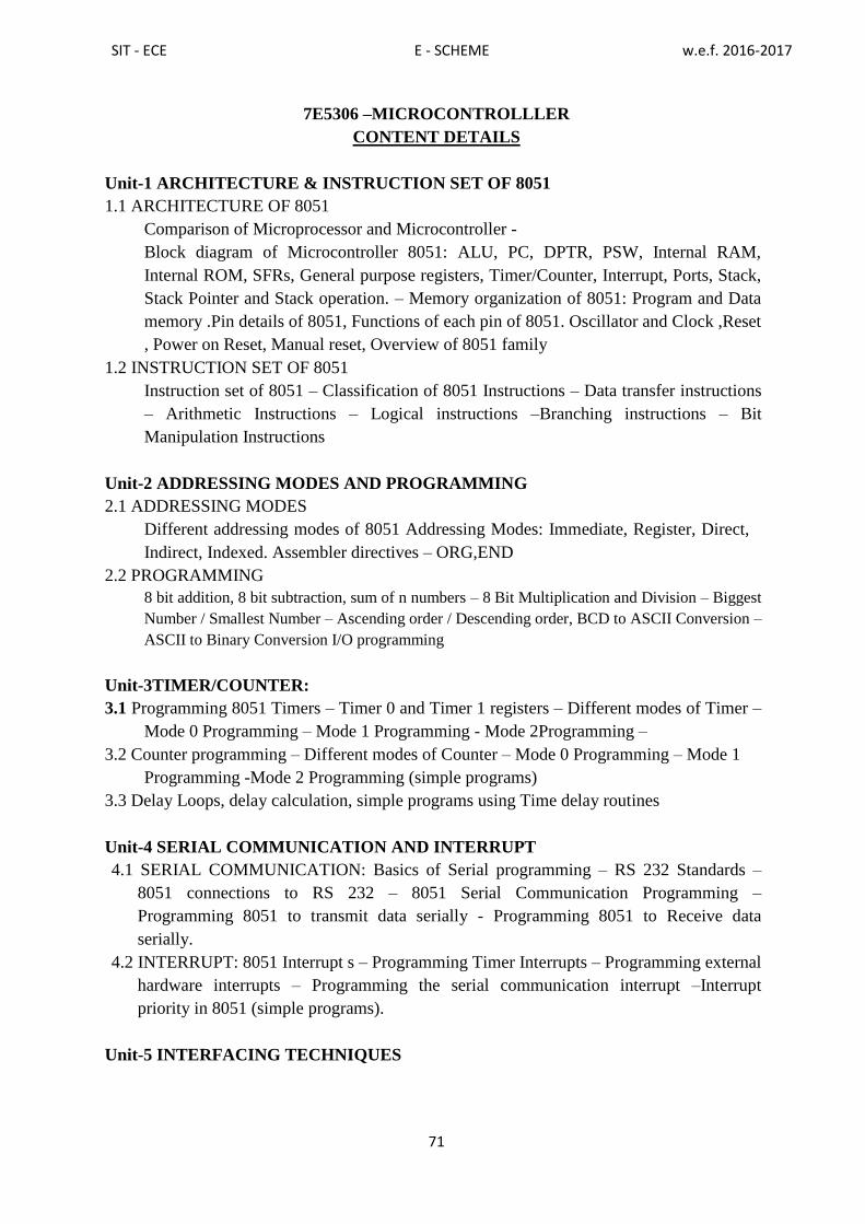
SIT - ECE E - SCHEME w.e.f. 2016-2017
71
7E5306 –MICROCONTROLLLER
CONTENT DETAILS
Unit-1 ARCHITECTURE & INSTRUCTION SET OF 8051
1.1 ARCHITECTURE OF 8051
Comparison of Microprocessor and Microcontroller -
Block diagram of Microcontroller 8051: ALU, PC, DPTR, PSW, Internal RAM,
Internal ROM, SFRs, General purpose registers, Timer/Counter, Interrupt, Ports, Stack,
Stack Pointer and Stack operation. – Memory organization of 8051: Program and Data
memory .Pin details of 8051, Functions of each pin of 8051. Oscillator and Clock ,Reset
, Power on Reset, Manual reset, Overview of 8051 family
1.2 INSTRUCTION SET OF 8051
Instruction set of 8051 – Classification of 8051 Instructions – Data transfer instructions
– Arithmetic Instructions – Logical instructions –Branching instructions – Bit
Manipulation Instructions
Unit-2 ADDRESSING MODES AND PROGRAMMING
2.1 ADDRESSING MODES
Different addressing modes of 8051 Addressing Modes: Immediate, Register, Direct,
Indirect, Indexed. Assembler directives – ORG,END
2.2 PROGRAMMING
8 bit addition, 8 bit subtraction, sum of n numbers – 8 Bit Multiplication and Division – Biggest
Number / Smallest Number – Ascending order / Descending order, BCD to ASCII Conversion –
ASCII to Binary Conversion I/O programming
Unit-3TIMER/COUNTER:
3.1 Programming 8051 Timers – Timer 0 and Timer 1 registers – Different modes of Timer –
Mode 0 Programming – Mode 1 Programming - Mode 2Programming –
3.2 Counter programming – Different modes of Counter – Mode 0 Programming – Mode 1
Programming -Mode 2 Programming (simple programs)
3.3 Delay Loops, delay calculation, simple programs using Time delay routines
Unit-4 SERIAL COMMUNICATION AND INTERRUPT
4.1 SERIAL COMMUNICATION: Basics of Serial programming – RS 232 Standards –
8051 connections to RS 232 – 8051 Serial Communication Programming –
Programming 8051 to transmit data serially - Programming 8051 to Receive data
serially.
4.2 INTERRUPT: 8051 Interrupt s – Programming Timer Interrupts – Programming external
hardware interrupts – Programming the serial communication interrupt –Interrupt
priority in 8051 (simple programs).
Unit-5 INTERFACING TECHNIQUES

SIT - ECE E - SCHEME w.e.f. 2016-2017
72
5.1. INTERFACING TECHNIQUES:Interfacing input switches, keyboard, Seven segment
LED Display, Analog to Digital converter (ADC), Digital to analog converter (DAC),
Stepper Motor, DC motor using PWM with 8051 microcontroller.
5.2 Applications: Temperature indicator using temperature sensor LM35, ADC,
Microcontroller, 7 segments LED. GSM based Security Application- using GSM
Modem, Microcontroller
Text Books:
Sl.
No. Name of the Book Author Publisher
1 The 8051 microcontroller and
embedded systems
Muhammed Ali Mazidi
Janice GillispieMazidi
Rolin D.McKinlay
Pearson
Education
2nd
edition 2006
2
The 8051 Microcontroller
Architecture, Programming &
Applications.
Kenneth J.Ayala
Penram
International
2nd
edition 1996
Reference Books :
Sl.
No. Name of the Book Author Publisher
1 Programming and Customizing the
8051 Microcontroller Mykepredko
Tata McGraw Hill
3rd
edition 2007
2 Design with Micro controllers John B. Peatman McGraw Hill
1988
Online Resources:
http://nptel.ac.in/courses/Webcourse-contents/IIT-
KANPUR/microcontrollers/micro/ui/TOC.htm
http://freevideolectures.com/Course/3018/Microprocessors-and-Microcontrollers
https://www.youtube.com/watch?v=liRPtvj7bFU
Course Outcomes:
At the end of the course the student will be able to:
CO1 Explain about Architecture, pin details of 8051 Microcontroller and instruction sets
CO2 Identify the addressing modes of instructions and write programs.
CO3 Explain about the various modes of timer/counter and its functions
CO4 Explain the concepts of interrupts and its types, serial data communication and
programming techniques
CO5 Interface various devices and develop a microcontroller based systems

SIT - ECE E - SCHEME w.e.f. 2016-2017
73
7E5307 - VERYLARGE SCALE INTEGRATION
Rationale: Very LargeScaleintegrationtechnology,whenespecially usedfor digitalintegrated
circuitdesign,isthatitis mandatory the behavior ofthe requiredsystem tobe
described(modeled)andverified(simulated) before synthesistoolstranslatethe
designintorealhardwarefabrication inthefoundry(gatesandwires).HardwareDescription
Language(HDL) allowsdesignstobedescribedusingany methodology -topdown, bottom up
ormiddle out. VHDL can be used to describe hardware at the gate
levelorinamoreabstractway.Thiscourseisto introducethedigital system designconcepts
through hardware description L a n g u a g e , VHDLprogramming,designflow ofVLSI,and
a r ch i t e c t u r e s of C P LD and FPGA.Itis mainlyaimedatdesignofcombinational
andsequential functions atgate/behaviourallevelandsimulatesand verifiestheir
functionalityusing the Hardware DescriptionLanguage (VHDL)
Course objectives:
The student should be made to:
Understand device level implementation of digital gates.
Understand the combinational circuit design and optimizing of the gate
Design a combinational circuit for any custom made application
Develop a VHDL code for any combinational circuit
Answer the VHDL primitives and the importance of VHDL code in a digital circuit
Design a digital circuit with Multiplexers and Encoders
Understand the functionality of various flipflops through its excitation table.
Explain the style of moore and mealy type machines
Understand to implement VHDL code for various flipflops
Understand the importance of, PLA, PROM, PAL, PLD, CPLD and FPGA
Scheme of Instruction and Examination
Course code Instruction Examinations
7E5307
Hours/
week
Hours/
Term Credits
Marks Duration
Internal External Total 3 Hrs
5 75 5 25 75 100
UNITS - ALLOCATION OF HOURS AND MARKS
Unit no. Name of the Topic Hours Marks
I CombinationalCircuitDesign 13 15
II VHDLforCombinationalCircuit 13 15
III SequentialCircuitDesign 13 15
IV VHDLforSequentialCircuit 13 15
V PLDS andFPGA 13 15
Cycle Tests, Model Exam& Revision classes 10 -

SIT - ECE E - SCHEME w.e.f. 2016-2017
74
7E5307 – VERYLARGE SCALE INTEGRATION
CONTENT DETAILS
Unit-1 COMBINATIONAL CIRCUIT
1.1 COMBINATIONAL CIRCUIT DESIGN: NMOS and CMOS logic implementation of
Switch, NOT, AND, OR, NAND, and NOR Gates. Digital logic variable, functions,
inversion, gate/circuits, Boolean algebra and circuit synthesis using gates (Up to4 variables).
1.2 COMBINATIONAL CIRCUIT BUILDING BLOCKS:
Circuit synthesis using Multiplexer, Demultiplexer, Encoders and Decoders, Arithmetic
adder(half adder, full adder ,4 bit adder, Sub tractor ,half Subtractor, full Subtractor,4 bit
Subtractor) and Comparator circuits. Hazards and races
Unit-2 VHDL FOR COMBINATIONAL CIRCUIT
2.1 VHDL FOR COMBINATIONAL CIRCUIT: Introduction to VLSI and its design
process. Introduction to CAD tool and VHDL: Design Entry, Synthesis, and Simulation.
Introduction to HDL and different level of abstractions. Behavioural modeling, dataflow
modeling, structural modeling. HDL Statements and Assignments.
2.2 VHDL CODE: AND, OR, NAND, NOR gates, Implementation of Mux, Demux,
Encoder, decoder. Four bit Arithmetic adder, subtractor and comparator in VHDL.
Unit-3 SEQUENTIAL CIRCUIT
3.1 SEQUENTIAL CIRCUIT DESIGN: Introduction/Refreshing to Flip-Flops( RS ,JK,
,D ,T) and its excitation table, counters and Shift registers(SISO,SIPO,PISO,PIPO).
3.2 DESIGN STEPS: State diagram, State table, state assignment. Example for moore and
mealy machines. Design of modulo counter (upto 3 bit)with onlyDflip-flops through state
diagram
Unit-4 VHDL FOR SEQUENTIAL CIRCUIT
4.1 VHDL FOR SEQUENTIAL CIRCUIT: VHDL constructs for storageelements. VHDL
code for D Latch / D, JK and T Flip-flops with or without reset input.
4.2 VHDL EXAMPLES: Counters: Synchronous counters-2 bit &3 bit up counter. 3 bit
up/downcounter. Decade counter,Johnson Counter.
Unit-5 PLDSAND FPGA
5.1PLDS Introduction to PLA and PAL.Implementationof combinational circuits with PAL
and PLA (up to 4 variables).Comparison between PROM, PAL and PLA. Introduction to
Complex Programmable Logic device (CPLD).
5.2 FPGA: Field Programmable Gate Array (FPGA).Introduction to ASIC. Types Of
(2+2+3+3)
Total 75 75

SIT - ECE E - SCHEME w.e.f. 2016-2017
75
ASIC.(full custom ASICs, Semi custom ASICs)
Text Books :
Sl.
No. Name of the Book Author Publisher
1
Fundamentals ofDigitalLogicwith
VHDL design
Stephen
brownandVranesic
McGrawHill
2 VHDL Primer Bhasker “J Prentice Hall
India
Reference Books :
Sl.
No. Name of the Book Author Publisher
1 Digital Design M.Morris Mano Michael
D Ciletti
“Pearson Education
2008
2 Digital Electronicswith PLD
Integration
NigelP. Cook Prentice Hall,
3 Programmable LogicHandbook: PLD,
CPLD and FPGA
AshokK.Sharma, Mcgraw-Hill,
4 Digital Logic Simulation and CPLD
Programmingwith VHDL
Steve Waterman
Prentice Hall,
Online Resources:
http://freevideolectures.com/Course/2327/VLSI-Circuits
http://www.nptelvideos.in/2012/12/digital-vlsi-system-design.html
Course Outcomes:
At the end of the course the student will be able to:
CO1 Be familiar with gates,MOSFET SWITCHES and combinational circuit design.
CO2 Understand about the programming concepts of combinational circuit using
VHDL. CO3 Design sequential circuits.
CO4 Understand about the programming concepts of sequential circuit using VHDL.
CO5 Explain about PLA,PAL,PLD‟s ,CPLD and FPGA.

SIT - ECE E - SCHEME w.e.f. 2016-2017
76
7E5308.1 - DIGITAL COMMUNICATION
Rationale:
Today, the growth of any industry depends upon electronics and communication.
There is the need for digital techniques in each and every field. The reason behind the
introduction of this course is to impart technical excel hence in the field of digital
communication by analyzing the various digital transmission methods, error control methods
and understanding about the multiple access communication.
Course Objectives :
Students must be able:
To know the Basics of Digital Communication
To study about the various types of signals
To study about the data transmission
To understand the Baseband system and sampling
To learn about PCM waveform types
To study about M-ary pulse modulation
To learn about rationale for coding
To learn about types of coding methods
To study about various error control codes
To know the Digital modulation techniques
To learn about TDM frame structure
To study about coherent detection of PSK, FSK
To understand the Spread spectrum communication
To study the Jamming consideration
To study about CDMA Digital cellular system
Scheme of Instruction and Examination
Course code Instruction Examinations
7E5308.1
Hours/
week
Hours/
Term Credits
Marks Duration
Internal External Total 3 Hrs
5 75 5 25 75 100
UNITS - ALLOCATION OF HOURS AND MARKS
Unit no. Topics Hours Marks
I Basics of Digital Communication 13 15
II Formatting and Base Band Modulation 13 15
III Baseband Coding Techniques 13 15
IV Digital Modulation Techniques 13 15
V Spread Spectrum Techniques 13 15

SIT - ECE E - SCHEME w.e.f. 2016-2017
77
7E5308.1 - DIGITAL COMMUNICATION
CONTENT DETAILS
Unit-1 BASICS OF DIGITAL COMMUNICATION
1.1 Digital communication signal processing – Typical Block diagram and transformations -
Advantages over analog communication – Channels for Digital communication-
Telephone, Optical fiber, Satellite.
1.2 Classification of signals- deterministic and random signals - periodic and non-periodic
signals – analog and discrete signals - energy and power signals - unit impulse function.
Information capacity (Definition only) – Shannon‟s limit for information capacity
(Definition only) - Data transmission - Serial and parallel transmission -Synchronous and
asynchronous transmission.
Unit-2 FORMATTING AND BASE BAND MODULATION
2.1 Base band system - The Sampling Theorem –impulse sampling- natural sampling- sample
and hold operation - Spectra- Nyquist Theorem - Aliasing – signal interface for a digital
system- Sampling and quantizing effects- Quantization noise – channel effects – channel
noise – PCM - Uniform and Non-uniform Quantization,
2.2 Baseband transmission
PCM waveform types- non return-to-zero(NRZ)- return-to-zero (RZ)- phase encoded –
multilevel binary – spectral attributes of PCM waveforms – Bits per PCM word and Bits
per symbol- PCM word size - M-ary pulse modulation waveforms.
Unit-3 BASEBAND CODING TECHNIQUES
3.1 Rationale for coding – Types of codes – Discrete memory less channel – Error control
coding methods – forward error correction – error detection with retransmission – types
of errors – random error and burst error
3.2 Principles of linear block codes – Hamming code – Binary cyclic codes – Cyclic
redundancy check code (CRC) – Convolution code
Unit-4 DIGITAL MODULATION TECHNIQUES
4.1 Digital modulation techniques – Listing of various types – Coherent binary modulation
techniques – Coherent quadrature modulation techniques – Non Coherent binary
modulation techniques. Minimum shift keying (MSK) - Block diagram of MSK
transmitter and receiver
4.2 DM-Frame structure, ASCII framing- E1 Framing, T1 Framing for telephone.
Detection of signals – coherent detection of PSK – sampled matched filter –coherent
detection of FSK – Non-coherent detection - Binary differential PSK.
Unit-5 SPREAD SPECTRUM TECHNIQUES
5.1 Spread spectrum communication - Beneficial attributes of spread spectrum systems –
Pseudo noise sequences – Randomness properties – Balance property, Run property and
Correlation property
Cycle Tests, Model Exam& Revision classes
(2+2+3+3) 10
-
Total 75 75

SIT - ECE E - SCHEME w.e.f. 2016-2017
78
5.2 Direct sequence spread spectrum systems – Processing gain and performance –
Frequency hopping systems – Frequency hopping with diversity – fast hopping versus
slow hopping
5.3 Synchronization – Jamming consideration – Commercial application – CDMA Digital
cellular system
Text Books:
SL.
No
Title Author Publisher with
Edition
1 Digital communications Fundamentals
& Applications
Bernard Sklar&
Pabitra Kumar Ray
Pearson -Second
edition -2009
2 Digital Communications Simon Haykin John Wiley India
edition -2006
Reference Books :
SL.
No
Title Author Publisher with
Edition
1 Digital communication Dr. J.S.Chitode Technical
Publications -Pune
Second edition,2011
2 Digital and analog communication
system
B.P.Lathi .Zhi Ding International 4th
Edition - OXFORD
university press.
3 Digital Communication P.Ramakrishna Rao TMH
2011
4 Principles of Communications system Taub&Schilling TMH
Third edition,2008
5 Digital communications John G.Prokais 2011
6 Digital communications Dr.K.N.Hari Bhat
Dr.D.Ganesh Rao
Sanguine Technical
Publisher
2005
Online Resources:
http://www.nptelvideos.in/2012/12/digital-communication.html
https://www.youtube.com/playlist?list=PLA5C2F41190F383E4
Course Outcomes:
At the end of the course the student will be able to:
CO1 Know the basics of digital communication
CO2 Understand the formatting and base band modulation
CO3 Explain about baseband coding techniques

SIT - ECE E - SCHEME w.e.f. 2016-2017
79
CO4 Explain about digital modulation techniques
CO5 Explain about spread spectrum techniques
7E5308.2 - BIOMEDICAL INSTRUMENTATION
Rationale:
Bio medical engineering education isin the growing stage. But every
year,thereisatremendousincreaseintheuseofmodernmedicalequipment
inthehospitalandhealthcareindustry thereforeitisnecessary forevery
studenttounderstandthe functioning of various medical equipment‟s.This course to
enable thestudents to learn thebasic principles ofdifferent biomedicalinstruments
vizClinicalmeasurement,Bio-medicalrecorders,
Therapeuticinstruments,Biotelemetry andModernimagingtechniques instruments.
Course Objectives:
The student should be made to:
Understand the generation of Bio-potential and its measurement using various
electrodes.
Understand the methods of measurement of blood pressure, lung volume,
respiration rate, body temperature and skin temperature.
Understand the principles of operations of ECG recorder, EEG recorder and ENG
recorder
Understand the working principles of audio meter, pacemaker and ventilators.
The basic principle of short wave diathermy.
The working principles of telemetry and telemedicine
To learn about the importance of patient safety and various methods of accident
prevention
The basic principle of CT, MRI scanner and operation of various imaging
techniques
Scheme of Instruction and Examination
Course code Instruction Examinations
7E5308.2
Hours/
week
Hours/
Term Credits
Marks Duration
Internal External Total 3 Hrs
5 75 5 25 75 100
UNITS - ALLOCATION OF HOURS AND MARKS
Unit no. Topics Hours Marks
I Bio-Electric Signalsand Electrodes &Clinical
Measurement 13
15
II Bio-MedicalRecorders 13 15
III TherapeuticInstruments 13 15

SIT - ECE E - SCHEME w.e.f. 2016-2017
80
7E5308.2 - BIOMEDICAL INSTRUMENTATION
CONTENT DETAILS
Unit-1 BIO-ELECTRIC SIGNALS, ELECTRODES AND CLINICAL
MEASUREMENT:
1.1 BIO-ELECTRIC SIGNALS ELECTRODES
Elementary ideas of cell structure, Bio – potential and their generation–resting and
action potential– propagation of action potential. Electrodes– Micro – Skin surface–
needle electrodes.
1.2 CLINICAL MEASUREMENT:
Measurement of Blood pressure (direct, indirect)– blood flow meter (Electro
magnetic& ultrasonic blood flowmeter)– blood pH measurement- Measurement of
Respiration rate– measurement of lung volume– heart rate measurement–
Measurement of body and skin temperature- Chromatography, Photometry,
Flurometry.
Unit-2 BIO - MEDICAL RECORDERS:
2.1 Electro cardiograph (ECG)– Lead system– ECG electrodes– ECG amplifiers– ECG
recording units– analysis of ECG curves.
2.2 Nervous system– EEG recorder– 10-20 lead system– recording techniques – EEG
wave types– Clinical use of EEG– brain tumour
2.3 Electro– myograph (EMG) – EMG waves– measurement of conduction velocity
– EMG recording techniques– Electroretinograph (ERG) Audiometer– principle– types
– Basic audiometer working.
Unit-3 THERAPEUTIC INSTRUMENTS:
3.1 Cardiac pacemaker – classification – External pace makers– implantable pacemaker–
pacing techniques– programmable pacemaker
3.2 Cardiac defibrillators – types – AC and DC defibrillators- Heart lung machine with
Block diagram.
3.3 Dialysis–Hemo dialysis– peritoneal dialysis.
3.4 Endoscopes Endoscopic laser coagulator and applications– physiotherapy equipment–
shortwave diathermy– micro wave diathermy–ultrasonic therapyunit(block/ circuit)
3.5 Ventilators– types – modern ventilator blockdiagram.
Unit -4 BIOTELEMETRY AND PATIENT SAFETY:
4.1 Introduction to biotelemetry– physiological parameters adaptable to biotelemetry–
components of a biotelemetry system– application of telemetry–elements of
biotelemetry; biotelemetry transmitter and receiver– Requirements for biotelemetry
IV Bio-Telemetry and Patient Safety 13 15
V Modern Imaging Techniques 13 15
Cycle Tests, Model Exam& Revision classes
(2+2+3+3) 10
-
Total 75 75

SIT - ECE E - SCHEME w.e.f. 2016-2017
81
system– radio telemetry with sub carrier- single channel and multichannel telemetry–
Telemedicine-introduction, working, applications.
4.2 Patient safety: Physiological effects of electric current– Micro and macro shock–
leakage current– shock hazards from electrical equipment. Methods of Accident
Prevention–Grounding – Double Insulation – Protection by low voltage– Ground fault
circuit interrupter– Isolation of patient connected parts– Isolated power distribution
system. Safety aspects in electro surgical units– burns, high frequency current hazards,
Explosion hazards.
Unit-5 MODERN IMAGING TECHNIQUES:
5.1 LASER beam properties– block diagram and principle of laser action – operation
ofCO2 and NDYag LASER – applications of LASER in medicine.
5.2 X ray apparatus– block diagram– operation– special techniques in X-ray imaging –
Tomogram– computerized Axial tomography.
5.3 Ultrasonic imaging techniques – Echo cardiography– Angiography–CT scanner -
Magnetic resonance imaging techniques
Text Books:
SL.
No
Title Author Publisher with
Edition
1 Biomedical Instrumentation Dr.M. Arumugam Anuradha
publications
2 Bio medical Instrumentation and
measurements
Leslie Cromwell –Fred j.
Wibell, Erich A.P Feither
Prentice-Hall
Reference Books :
SL.
No
Title Author Publisher with
Edition
1 Medicine and clinical
Engineering
Jacobson and Webstar Prentice-Hall
2 Hand book of Bio –Medical
Instrumentation
R.S .Khandpur Tata McGraw-Hill
Education, 2003
3 Medical Electronics Kumara doss Cambridge
University-2nd
edition Press -2003
4 Introduction to Medical
Electronics
. B.R. Klin Mc graw hill
international edition,
3rd edition, 1989
5 Introduction to Biomedical
Instrumentation
Mandeep Singh PHI Learning Pvt.
Ltd, 2nd edition 2010
Online Resources:
www.youtube.com/watch?v=1ovv6lmPHSI https://www.youtube.com/watch?v=Sn0bOX5Hau4
http://freevideolectures.com/Course/2387/Frontiers-of-Biomedical-Engineering
https://www.youtube.com/watch?v=JC_TDo0xSb4
Course Outcomes:

SIT - ECE E - SCHEME w.e.f. 2016-2017
82
At the end of the course the student will be able to:
CO1 Explain about Bio - electric signals, electrodes and clinical measurement
CO2 Explain about Bio - medical recorders
CO3 Explain about Therapeutic instruments
CO4 Explain about Biotelemetry and patient safety
CO5 Explain about Modern imaging techniques
7E5308.3 - ELECTRONIC SYSTEM DESIGN
Rationale:
The rationale behind introducing this course is to make the students understand the structure,
working and all other relevant aspects of electronic systems which has become an integral
part of Electronic media which is growing at an exponentially high rate all around the world.
Course Objectives:
The student should be made to:
Understand to design of DC regulated power supply of various voltages with
different protection circuits.
Understand the design of different types of amplifiers for various application.
Understand the use of various transducers and make use them.
Design various systems using the analog data collected from transducers
Understand the use of microcontrollers for various application
Scheme of Instruction and Examination
Course code Instruction Examinations
7E5308.3
Hours/
week
Hours/
Term Credits
Marks Duration
Internal External Total 3 Hrs
5 75 5 25 75 100
UNITS - ALLOCATION OF HOURS AND MARKS
Unit no. Topics Hours Marks
I Design of Power Supply 13 15
II Design of Small Signal Amplifiers 13 15
III Data Acquisition System 13 15
IV Design of Function Generators 13 15
V High Voltage/High Current Driver 13 15
Cycle Tests, Model Exam& Revision classes
(2+2+3+3) 10
-
Total 75 75

SIT - ECE E - SCHEME w.e.f. 2016-2017
83
7E5308.3 - ELECTRONIC SYSTEM DESIGN
CONTENT DETAILS
Unit-1 DESIGN OF POWER SUPPLY
1.1DC power supply with filters - Regulators and their types - Protection circuits
1.2 Multi output and variable power supply design - Rectifiers – types - half wave, full
wave.
Unit-2 DESIGN OF SMALL SIGNAL AMPLIFIERS
2.1 CB,CE configuration - Emitter follower - Darlington pair amplifiers with and without –
Bootstrapping - Two stage direct coupled amplifiers
2.2 Design of audio power amplifier with drivers - Design of simple PA system - Voltage to
current converter, current to voltage converter
Unit-3 DATA ACQUISITION SYSTEM
3.1 Analog to digital converter (ADC) - Digital to analog converter (DAC) - Design of
Instrumentation amplifier with the bridge type
3.2 Transducer - Temperature measurement - Design of Electronic voltmeter and ammeter -
Design of – multimeter - Display system.
Unit-4 DESIGN OF FUNCTION GENERATORS
4.1 Design of AM signal using multiplier IC - AM signal demodulation using envelope
detector - Design of FM signal using VCO (using IC NE566) -
4.2 FM signal demodulation using phase discriminator and ratio detector
Unit-5 HIGH VOLTAGE/HIGH CURRENT DRIVER
5.1 Circuit for Relay and motor control applications - Microcontroller based closed loop
system - Security systems, Scrolling display
5.2 Microcontroller based stepper motor - Microcontroller based temperature sensor and
relay

SIT - ECE E - SCHEME w.e.f. 2016-2017
84
Text Books:
SL.
No
Title Author Publisher with Edition
1 A Monograph on Electronic s
Design Principles,
N.C.Goyel,
R.K.Khetan,
Khanna Publishers -Second
Edition
Reference Books:
SL.
No
Title Author Publisher with Edition
1 Electronic devices and circuits Allen Mottershead Prentice hall of indiapvt
limited, 19th edition, 1997
2 The art of electronics Paul Horowitz Cambridge University-2nd
edition Press -2003
3 Electronic principles and
applications
Charles.A.Schuler Mc graw hill international
edition, 3rd edition, 1989
4 8051 Micro controllers Mazidi and
D.Mackinlay
Pearson education , low
Online Resources:
www.youtube.com/playlist?list=PL4C141B35706AD19A
http://www.nptelvideos.in/2012/12/circuits-for-analog-system-design.html
Course Outcomes: At the end of the course the student will be able to:
CO1 Design power supply
CO2 Design of small signal amplifiers
CO3 Understand the principle of data acquisition system
CO4 Design of function generators
CO5 High voltage/high current driver

SIT - ECE E - SCHEME w.e.f. 2016-2017
85
7E5309 - ADVANCED COMMUNICATION SYSTEMS LAB
Rationale:
Even though the field of electronics and communication engineering changes so fast,
the principles do not change. The lab will make the students to understand and analyze the
operation of electronic circuits. Today, communications is the largest sector of the
electronics field. So the knowledge and understanding of communications is a must for ECE
students
Course Objectives:
After completion of this lab, the students will be able to
Trace the PSK modulation and demodulation waveforms.
Transmit and receive using Fiber optic links.
Understand the principles of ASK, TDM and PCM
Construct and test Analog transmitter and receiver.
Scheme of Instruction and Examination
SCHEME OF EVALUATION
SL.NO DESCRIPTION MARKS
1. CIRCUITDIAGRAM 20
2. CONNECTION 25
3. EXECUTION 15
4. RESULT & GRAPH 10
5. VIVA–VOCE 05
6. TOTAL 75
Course code Instruction Examinations
7E5309
Hours/ week Hours/
Term Credits
Marks Duration
Internal External Total
3 Hrs Tutorial practical 75 3 25 75 100
1 4
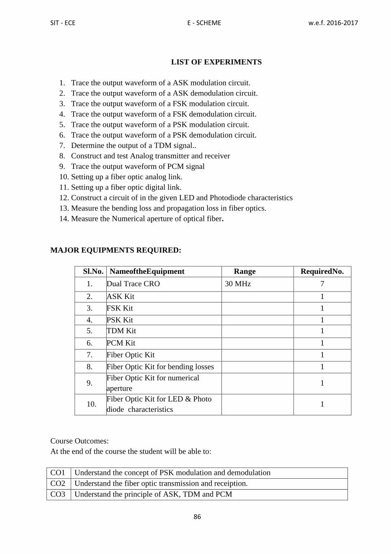
SIT - ECE E - SCHEME w.e.f. 2016-2017
86
LIST OF EXPERIMENTS
1. Trace the output waveform of a ASK modulation circuit.
2. Trace the output waveform of a ASK demodulation circuit.
3. Trace the output waveform of a FSK modulation circuit.
4. Trace the output waveform of a FSK demodulation circuit.
5. Trace the output waveform of a PSK modulation circuit.
6. Trace the output waveform of a PSK demodulation circuit.
7. Determine the output of a TDM signal..
8. Construct and test Analog transmitter and receiver
9. Trace the output waveform of PCM signal
10. Setting up a fiber optic analog link.
11. Setting up a fiber optic digital link.
12. Construct a circuit of in the given LED and Photodiode characteristics
13. Measure the bending loss and propagation loss in fiber optics.
14. Measure the Numerical aperture of optical fiber.
MAJOR EQUIPMENTS REQUIRED:
Sl.No. NameoftheEquipment Range RequiredNo.
1. Dual Trace CRO 30 MHz 7
2. ASK Kit 1
3. FSK Kit 1
4. PSK Kit 1
5. TDM Kit 1
6. PCM Kit 1
7. Fiber Optic Kit 1
8. Fiber Optic Kit for bending losses 1
9. Fiber Optic Kit for numerical
aperture 1
10. Fiber Optic Kit for LED & Photo
diode characteristics 1
Course Outcomes:
At the end of the course the student will be able to:
CO1 Understand the concept of PSK modulation and demodulation
CO2 Understand the fiber optic transmission and receiption.
CO3 Understand the principle of ASK, TDM and PCM

SIT - ECE E - SCHEME w.e.f. 2016-2017
87
CO4 Understand Analog transmission and reception
7E5310 - MICROCONTROLLLER LAB
Rationale:
This lab helps the students to improve their programming skills. Both software and
Hardware (Interfacing Experiments) programs are incorporated in this lab. Microcontrollers
are used in video games, automobiles, toys and every electronic device imaginable to
perform specific functions and enrich our lives. The study of microcontroller will make the
students equippedfor thedevelopment of embedded systems.
Course Objectives:
After completion of this lab, the students will be able to
Write and execute Assembly Language Programs
Generate square waves using in built timer
Understand the interrupts
Interface the peripheral and write programs
Scheme of Instruction and Examination
SCHEME OF EVALUATION
SL.NO DESCRIPTION MARKS
1. PROGRAM 25
2. OPCODE & ADDRESS 10
3. EXECUTION 25
4. RESULT 10
5. VIVA–VOCE 05
Course code Instruction Examinations
7E5310
Hours/ week Hours/
Term Credits
Marks Duration
Internal External Total
3 Hrs Tutorial practical 75 3 25 75 100
1 4
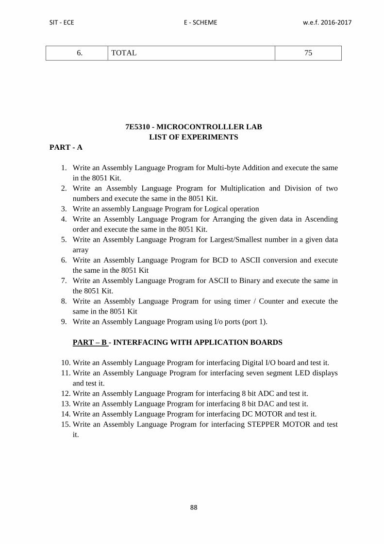
SIT - ECE E - SCHEME w.e.f. 2016-2017
88
6. TOTAL 75
7E5310 - MICROCONTROLLLER LAB
LIST OF EXPERIMENTS
PART - A
1. Write an Assembly Language Program for Multi-byte Addition and execute the same
in the 8051 Kit.
2. Write an Assembly Language Program for Multiplication and Division of two
numbers and execute the same in the 8051 Kit.
3. Write an assembly Language Program for Logical operation
4. Write an Assembly Language Program for Arranging the given data in Ascending
order and execute the same in the 8051 Kit.
5. Write an Assembly Language Program for Largest/Smallest number in a given data
array
6. Write an Assembly Language Program for BCD to ASCII conversion and execute
the same in the 8051 Kit
7. Write an Assembly Language Program for ASCII to Binary and execute the same in
the 8051 Kit.
8. Write an Assembly Language Program for using timer / Counter and execute the
same in the 8051 Kit
9. Write an Assembly Language Program using I/o ports (port 1).
PART – B - INTERFACING WITH APPLICATION BOARDS
10. Write an Assembly Language Program for interfacing Digital I/O board and test it.
11. Write an Assembly Language Program for interfacing seven segment LED displays
and test it.
12. Write an Assembly Language Program for interfacing 8 bit ADC and test it.
13. Write an Assembly Language Program for interfacing 8 bit DAC and test it.
14. Write an Assembly Language Program for interfacing DC MOTOR and test it.
15. Write an Assembly Language Program for interfacing STEPPER MOTOR and test
it.

SIT - ECE E - SCHEME w.e.f. 2016-2017
89
MAJOR EQUIPMENTS REQUIRED:
SL.NO NameoftheEquipment RequiredNos.
1. 8051MicrocontrollerKit with Keyboard 10
2. DigitalI/OInterfaceBoard 01
3. MatrixkeyboardInterfaceBoard 01
4. SevensegmentLEDdisplayInterfaceBoard 01
5. TrafficlightInterfaceBoard 01
6. 8bitADC InterfaceBoard 01
7. 8-bitDACInterfaceBoard 01
8. STEPPERMOTORCONTROLInterfaceBoard 01
9. DCmotorcontrolInterfaceBoard 01
Course Outcomes:
At the end of the course the student will be able to:
CO1 Understand the Assembly Language Programs
CO2 Understand the functions of inbuilt timer
CO3 Understand the functions of interrupt
CO4 Interface the peripherals and execute

SIT - ECE E - SCHEME w.e.f. 2016-2017
90
7E5311 - VERYLARGE SCALE INTEGRATION LAB
Rationale:
Today digital systems are designed by writing software in the form of hardware
description languages (HDLs). The most common HDLs used today are VHDL and
Verilog. This practical helps the students to improve their programming skills in the
hardware description language VHDL. The designer typically describes the behavior of the
logic circuit rather than writing traditional Boolean logic equations. In this practical
Computer-aided design tools are used to simulate the VHDL design and to synthesize the
design to actual hardware.
Course Objectives:
After completion of this lab, the students will be able to
Design, develop VHDL code for combinational circuits and simulate.
Design and Implement decoder, encoder, displays and Flipflops in FPGA kit
Scheme of Instruction and Examination
SCHEME OF EVALUATION
SL.NO DESCRIPTION MARKS
1. PROGRAM 20
2. TRUTHTABLE 10
3. SIMULATION 20
4. EXECUTION 10
5. RESULT 10
6. VIVA VOCE 5
7. TOTAL 75
Course code Instruction Examinations
7E5311
Hours/ week Hours/
Term Credits
Marks Duration
Internal External Total
3 Hrs Tutorial practical 75 3 25 75 100
1 4

SIT - ECE E - SCHEME w.e.f. 2016-2017
91
LIST OF EXPERIMENTS
1. SIMULATION OF VHDL CODE FOR COMBINATIONAL CIRCUIT
Optimize a 4-variable combinational function (SOP or POS), describe it in VHDL code
and simulate it. Example: F= (0,5,8,9,12) in SOP or POS.
2. SIMULATION OF VHDL CODE FOR ARITHMETIC CIRCUITS
Design and Develop the circuit for the following arithmetic function in VHDL Codes and
Simulate it. Addition, Subtraction Multiplication (4 x 4 bits)
3. SIMULATION OF VHDL CODE FOR MULTIPLEXER
Design and develop a 8 x1 multiplexer. Simulate the same code in the software
4. SIMULATION OF VHDL CODE FOR DEMULTIPLEXER
Design and develop an 8 output demultiplexer. Simulate the same code in the software
5. VHDL IMPLEMENTATION OF MULTIPLEXER
Describe the code for a multiplexer and implement it in FPGA kit in which switches are
connected for select input and for data inputs a LED is connected to the output.
6. VHDL IMPLEMENTATION OF DEMULTIPLEXER
Switches are connected for select inputs and a data input, Eight LEDs are connected to the
output of the circuit.
7. VHDL IMPLEMENTATION OF DECODER
8. VHDL IMPLEMENTATION OF 7 SEGMENT DECODER BY LUT
Develop a 7-segment decoder using Look up table. Describe the seven-segment decoder in
VHDL using developed Look up table. A seven-segment display is connected to the output
of the circuit. Four switches are connected to the input. The 4-bit input is decoded into 7
segment equivalent.
9. VHDL IMPLEMENTATION OF ENCODER
Design and develop HDL code for decimal (Octal) to BCD encoder. There will be10 input
switches (or 8 switches) and 4 LEDs in the FPGA kit. The input given from switches and it
is noted that any one of the switch is active. The binary equivalent for the corresponding
input switch will be glowing in the LED as output.
10. SIMULATION OF VHDL CODE FOR DELAY
Develop a VHDL code for making a delayed output for 1second or 2 seconds by assuming
clock frequency provided in the FPGA Kit.
11. VHDL IMPLEMENTATION FOR BLINKING A LED
Develop a VHDL Code for delay and verify by simulating it. This delay output is
connected to LED. Delay is adjusted such away LED blinks for every 1 or 2 seconds.
12. SIMULATE A VHDL TEST BENCH CODE FOR TESTING A GATE

SIT - ECE E - SCHEME w.e.f. 2016-2017
92
Develop a VHDL test bench code for testing any one of the simple gate. Simulate the test
bench code in the HDL software.
13. VHDL IMPLEMENTATION FOR BLINKING A ARRAY OF LEDS
Design and develop a VHDL Code for 4 bit binary up counter. Four LEDs are connected
at the output of the counter. The counter should up for every one seconds.
14. VHDL IMPLEMENTATION OF A SPELLER WITH AN ARRAY OF LEDS
Design and develop VHDL Code for a 5 bit Johnson ring counter 4 bit The LEDs are
connected at the output of the counter. The speller should work for every one seconds.
15. VHDL IMPLEMENTATION OF 7 SEGMENT DISPLAY
Design and develop a seven segment decoder in VHDL. Design and developa 4 bit BCD
counter, the output of the counter is given to seven segment decoder. A seven segment
display is connected to the output of the decoder. The display shows 0,1, 2.. 9 for every
one second
16. SIMULATION OF VHDL CODE FOR JK ,RS AND D FLIPFLOP.
HARDWAREREQUIREMENT:
DesktopComputers–30Nos
Spartan 3E Kit – 9 Nos
Stepper Motor Interfacing kit
SOFTWAREREQUIREMNT:
Xilinx software
Modelsim software
Course Outcomes:
At the end of the course the student will be able to:
CO1 Understand VHDL programming
CO2 Design and simulate combinational circuits
CO3 Implement and verify in FPGA kit

SIT - ECE E - SCHEME w.e.f. 2016-2017
93
VI - TERM

SIT - ECE E - SCHEME w.e.f. 2016-2017
94
7E6312 - EMBEDDED SYSTEMS
Rationale:
Increasingly, embedded systems developers and system-on-chip designers select
specific microprocessor cores and a family of tools, libraries, and off-the-shelf components
to quicklydevelop embedded system-based products. A major processor in this industry is
ARM. Since 1985, the ARM architecture has become the most pervasive 32-bit architecture
in the world. ARMprocessors are embedded in products ranging from cell/mobile phones to
automotive brakingsystems. A worldwide community of ARM partners and third-party
vendors has developed amongsemiconductor and product design companies, including
hardware engineers, system designers and software developers.
Course Objectives:
Understand the ARM design philosophy, ARM architecture and the pipeline
structure, RISC architecture
Describe the little and big-endian methods of representation
Explain the Instruction sets of ARM processor, various operational modes in
ARM processor
List the various exceptions and handling methods
Develop an assembly level code for basic arithmetic primitive operations
List and explain various cache mechanisms and cache policies
Explain the essential of cache memory, write buffers Lockdown and its
method
Explain the importance and functionality of MPU, MMU and virtual memory
Relate and distinguish between OS and RTOS in their functionality
Explain multitasking, scheduling, IPC, and synchronization
Scheme of Instruction and Examination
Course code Instruction Examinations
7E6312
Hours/
week
Hours/
Term Credits
Marks Duration
Internal External Total 3 Hrs
5 75 5 25 75 100
UNITS - ALLOCATION OF HOURS AND MARKS
Unit no. Topics Hours Marks
I ARM Processor Architecture Fundamentals 13 15
II ARM Instructions Sets, Interrupts 13 15
III Cache Mechanism 13 15
IV Memory Protection And Management 13 15
V Embedded OS and RTOS 13 15
Revision 3
Cycle Tests And Model Examination 7
Total 75 75

SIT - ECE E - SCHEME w.e.f. 2016-2017
95
7E6312 - EMBEDDED SYSTEMS
CONTENT DETAILS
Unit-1 ARM PROCESSOR ARCHITECTURE FUNDAMENTALS:
1.1 The RISC and ARM design philosophy, Embedded System Hardware. -Data Flow
model
1.2 CPU Registers, modes of operation-Current Program Status Register-Pipeline-
Exceptions-Interrupts, and the Vector TableARM nomenclature and families.
Unit-2 ARM INSTRUCTIONS SETS, INTERRUPTS,MODES
2.1ARM INSTRUCTIONS SETS, INTERRUPTS:ARM and Thumb Instruction Sets,
Data Processing Instructions, Branch Instructions, Load-Store Instructions(single
register only),Program Status Register Instructions, Conditional Execution, Stack
Instructions, and Software Interrupt Instruction.
2.2 ARM PROCESSOR EXCEPTIONS AND MODES: vector table, priorities, link
Register offsets, interrupts, and IRQ / FIQ exceptions interrupt stack design and
implementation Program for Addition, Subtraction, Multiplication in assembly
Unit-3 CACHE MECHANISM :
3.1 Introduction to cache memory, memory hierarchy and cache memory, Cache
architecture and cache policies.
3.2 CONCEPT OF FLUSHING AND CLEANING CACHE: Flushing and Cleaning
ARM cache core.
3.3 CONCEPT OF CACHE LOCKDOWN: Locking Code and Data in Cache. Cache and
write buffer
Unit-4 MEMORY PROTECTION AND MANAGEMENT UNIT:
4.1 Introduction to protection unit, Protected Regions, and Demonstration of an MPU
system. 4.2 Virtual Memory working principle
Unit-5 EMBEDDED OS AND RTOS:
5.1Fundamental Components to Embedded OS, Simple Little Operating System:
Initialization, memory Model, Scheduler..
5.2 INTRODUCTION TO RTOS: Real-time systems concepts, foreground/background
systems, critical sections, resources, multitasking, Context switching, scheduling, re-
entrancy, task priorities, Mutual exclusion.
5.3 SYNCHRONIZATION AND IPC: Introduction to Semaphores and types. Inter process
communication: pipes and message box.
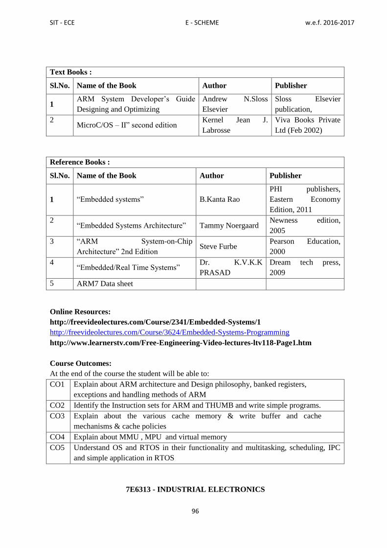
SIT - ECE E - SCHEME w.e.f. 2016-2017
96
Text Books :
Sl.No. Name of the Book Author Publisher
1 ARM System Developer‟s Guide
Designing and Optimizing
Andrew N.Sloss
Elsevier
Sloss Elsevier
publication,
2
MicroC/OS – II” second edition
Kernel Jean J.
Labrosse
Viva Books Private
Ltd (Feb 2002)
Reference Books :
Sl.No. Name of the Book Author Publisher
1 “Embedded systems” B.Kanta Rao
PHI publishers,
Eastern Economy
Edition, 2011
2
“Embedded Systems Architecture” Tammy Noergaard
Newness edition,
2005
3 “ARM System-on-Chip
Architecture” 2nd Edition Steve Furbe
Pearson Education,
2000
4 “Embedded/Real Time Systems”
Dr. K.V.K.K
PRASAD
Dream tech press,
2009
5 ARM7 Data sheet
Online Resources:
http://freevideolectures.com/Course/2341/Embedded-Systems/1
http://freevideolectures.com/Course/3624/Embedded-Systems-Programming
http://www.learnerstv.com/Free-Engineering-Video-lectures-ltv118-Page1.htm
Course Outcomes:
At the end of the course the student will be able to:
CO1 Explain about ARM architecture and Design philosophy, banked registers,
exceptions and handling methods of ARM
CO2 Identify the Instruction sets for ARM and THUMB and write simple programs.
CO3 Explain about the various cache memory & write buffer and cache
mechanisms & cache policies
CO4 Explain about MMU , MPU and virtual memory
CO5 Understand OS and RTOS in their functionality and multitasking, scheduling, IPC
and simple application in RTOS
7E6313 - INDUSTRIAL ELECTRONICS

SIT - ECE E - SCHEME w.e.f. 2016-2017
97
Rationale :
This course enables the students to know power devices and phase control circuits,
converters, choppers, UPS, SMPS and PLC. This will provide the student to know the
working principle of the power electronic equipment used in Industries. Many
manufacturing processes demand a sequence of operation, which are to be performed
repetitively. A PLC is a solid state device, designed to operate in noisy industrial
environments and can perform all logic functions. PLCs are widely used in all industries for
efficient control operations.
Course Objectives:
The student should be made to:
Understand the working principle of SCR, MOSFET,
IGBT,GTO,LASER
Studythe methods oftriggering
Learn about the operation of converters and its types.
Understand the various types of commutation.
Learn about the operation of choppers.
Learn about the operation of inverters and types.
Understand the concept ofHVDC.
Knowabout working principle of SMPS, UPS and its types.
Understand the concept ofHVDC.
Understand the functions of PLC.
Write ladder programs.
Scheme of Instruction and Examination
Course code Instruction Examinations
7E6313
Hours/
week
Hours/
Term Credits
Marks Duration
Internal External Total 3 Hrs
5 75 5 25 75 100
UNITS - ALLOCATION OF HOURS AND MARKS
Unit no. Topics Hours Marks
I PowerDevices 13 15
II Trigger Circuits and Converters 13 15
III Commutation & Chopper 13 15
IV Inverters &Applications 13 15
V Programmable Logic Controller 13 15
Cycle Tests, Model Exam& Revision classes
(2+2+3+3) 10
-
Total 75 75

SIT - ECE E - SCHEME w.e.f. 2016-2017
98
7E6313 - INDUSTRIAL ELECTRONICS
CONTENT DETAILS
Unit-1 POWER DEVICES
1.1 Thyristor family –Working principle, VI characteristics and switching characteristics of
SCR –Applications of SCR. Definitions for holding current, latching current, dv/dt rating,
di/dt rating-comparison between Thyristor and transistor. Light Activated Silicon
Controlled Rectifiers (LASCR )- Working principle, VI characteristics
1.2 Insulated gate bipolar transistor (IGBT), Power MOSFET and Gate turn off thyristor
(GTO)- Symbol, principle of working, VI characteristics and applications. Comparison
between power MOSFET, power transistor and power IGBT.
Unit-2 TRIGGER CIRCUITS AND CONVERTERS
2.1 TRIGGER CIRCUITS:Triggering of SCR- Gate triggering –Types–Concepts of
DC triggering, AC triggering, Pulse gate triggering– Pulse transformer in trigger
circuit– Electrical isolation by opto isolator - Resistance firing circuit and
waveform, Resistance capacitor firing circuit and waveform, Synchronized UJT
triggering (ramp triggering) circuit and waveform. Ramp and Pedestal triggering
circuit for AC loads.
2.2 CONVERTERS:Converters– Definition–Single phase Half controlled bridge
converter with R load and RL load-importance of flywheel diode–Single phase
fully controlled bridge converter with resistive load – voltage and current
waveforms–Single phase fully controlled bridge converter with RL load–voltage
and currentwaveforms.
Unit-3 COMMUTATION & CHOPPER
3.1Commutation-Natural commutation – Forced commutation – Types of
commutation – self commutation by resonating the load (class A), self-
commutation by an LC circuit ( class B) , complementary commutation (class C)
,Auxiliary commutation(class D) , External pulse commutation(class E) (voltage
and current commutation) Ac line commutation(class F).
3.2 Chopper – Definition –principle of DC chopper operation, control strategies(time ratio
control ,current limit control- step down, step up, step up/down chopper–Jones chopper
–Applications of DC chopper – Principle of working of single phase AC chopper –
Chopper using MOSFET. MOSFET based PWM chopper
Unit-4 INVERTERS &APPLICATIONS
4.1 INVERTERS: Inverter- Definition – Requirement of an inverter – Single phase inverter
with resistive load (parallel inverter) – Single phase inverter with RL load – Methods
to obtain sine wave output from an inverter- Output voltage control in inverters-Mc
Murray inverter–advantages- Parallel inverter using IGBT.
4.2 INVERTERAPPLICATIONS: HVDCTransmission – principle – advantages –
drawbacks SMPS- Block diagram of SMPS – advantages and disadvantages. –
Block diagram of SMPS– advantages and disadvantages. UPS-Type (ON Line, OFF
Line), Comparison. -online and offline UPS.

SIT - ECE E - SCHEME w.e.f. 2016-2017
99
Unit-5 PROGRAMMABLE LOGIC CONTROLLER
5.1 Introduction to PLC– Relays - Block diagram of PLC– Basics of Input and output
module (digital input and output module) Timer and counter (on timer, off
timer, retentive timer, up counter, down counter) -Logic functions – AND
logic, OR logic, NAND logic, EX-OR logic- symbols used in ladder logic diagram.
5.2 Ladder programming – Ladder diagram for simple systems–motor control, Star delta
starter, Conveyer control and Liftcontrol.
Text Books :
Sl.No. Name of the Book Author Publisher
1 Power Electronics M D Singh, K B
Khanchandani
Tata McGraw-Hill
2nd
edition 2008.
2
Power Electronics
M.H.Rashid
PHI Publication-
4th
edition 2013
Reference Books :
Sl.No. Name of the Book Author Publisher
1 PowerElectronics Dr.P.S.Bimbhra, Khannapublishers
2 Industrial&PowerElectronics HarishC.Rai UmeshPublication,
3 Programmable Logic
Controllers -
FrankD.Petruzela PHI publications
4 Programmable Logic
Controllers– Principles and
applications
JohnW.Webb. Ronald A.
Reis
PHI publications
2017
5 ProgrammableLogicController PradeepKumar&Srivashtava BPB Publications
Online Resources:
http://nptel.ac.in/downloads/108105066/
https://www.youtube.com/watch?v=1Auay7ja2oY
https://www.youtube.com/watch?v=_H00ZKEBbz8
https://www.youtube.com/playlist?list=PLB0B030A687A6ADD2
Course Outcomes: At the end of the course the student will be able to:
CO1 Understand the structure ,principle and charcteristics of various power devices .
CO2 Explain about the operations of trigger circuits and converters
CO3 Identify the types of commutation and working of choppers.
CO4 Understand the concept of inverters & its applications
CO5 Write ladder program using programmable logic controller
7E6314.1 - TELEVISION ENGINEERING
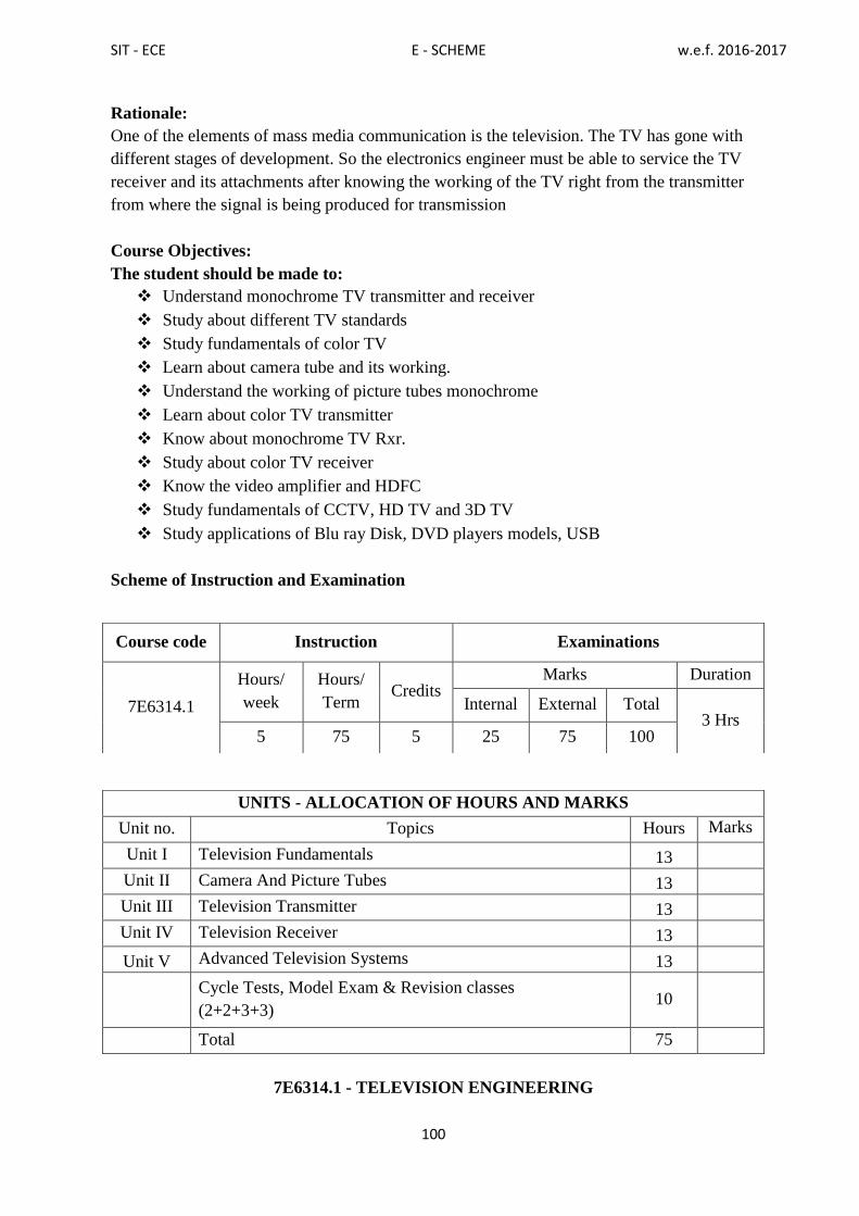
SIT - ECE E - SCHEME w.e.f. 2016-2017
100
Rationale:
One of the elements of mass media communication is the television. The TV has gone with
different stages of development. So the electronics engineer must be able to service the TV
receiver and its attachments after knowing the working of the TV right from the transmitter
from where the signal is being produced for transmission
Course Objectives:
The student should be made to:
Understand monochrome TV transmitter and receiver
Study about different TV standards
Study fundamentals of color TV
Learn about camera tube and its working.
Understand the working of picture tubes monochrome
Learn about color TV transmitter
Know about monochrome TV Rxr.
Study about color TV receiver
Know the video amplifier and HDFC
Study fundamentals of CCTV, HD TV and 3D TV
Study applications of Blu ray Disk, DVD players models, USB
Scheme of Instruction and Examination
7E6314.1 - TELEVISION ENGINEERING
Course code Instruction Examinations
7E6314.1
Hours/
week
Hours/
Term Credits
Marks Duration
Internal External Total 3 Hrs
5 75 5 25 75 100
UNITS - ALLOCATION OF HOURS AND MARKS
Unit no. Topics Hours Marks
Unit I Television Fundamentals 13
Unit II Camera And Picture Tubes 13
Unit III Television Transmitter 13
Unit IV Television Receiver 13
Unit V Advanced Television Systems 13
Cycle Tests, Model Exam & Revision classes
(2+2+3+3) 10
Total 75

SIT - ECE E - SCHEME w.e.f. 2016-2017
101
CONTENT DETAILS
Unit-1 TELEVISION FUNDAMENTALS
1.1 Monochrome TV: Basic block diagram of Monochrome TV transmitter and Receiver –
Scanning process – horizontal, vertical and sequential scanning – flicker – interlaced
scanning (qualitative treatment only) – need for synchronization – blanking pulses –
Aspect ratio– Resolution – Types – vertical and horizontal resolution – video bandwidth
– composite video signal (CVS)– CVS for one horizontal line – Definitions for Vertical
sync pulse, Serrated vertical pulse, Equalizing pulse – Positive & Negative modulation -
TV Standards – List of Types of TV standards.
1.2 Color T.V. Fundamentals: Additive mixing of colors –Types – color perception –
Chromaticity diagram – Definition for Luminance, Hue Saturation and Chrominance
Formation of chrominance signal in PAL system with weighting factors.
Unit-2 CAMERA AND PICTURE TUBES
2.1 CAMERA TUBE: Characteristics – Types of camera tube – workingprinciple of Vidicon
and Plumbicon camera tube, CCD camera – Video processing of camera pick up signal
– Block diagram and Principle of working of color TV camera tube.
2.2 PICTURE TUBE :Construction and working of Monochrome picture tube – screen
phosphor – screen burn – Screen Persistance - Aluminized screen – Types of color
picture tubes -construction and working principle of Delta gun and Trinitron Color
picture tubes – Automatic degaussing.
Unit-3 TELEVISION TRANSMITTER
3.1 Types –Comparison - Principle – Block diagram of Low level IF Modulated TV
transmitter –Visual Exciter –Aural Exciter – principle of working of CIN Diplexer –
Block diagram of color TV transmitter – color compatibility
3.2 PAL color coder –functional blocks and working of each block – Merits and demerits of
PAL system
Unit-4 TELEVISION RECEIVER
4.1 Block diagram of Monochrome Receiver – functions of each block – Need for AGC –
Advantages of AGC – Video amplifier requirements –High frequency & Low
frequency compensation – Block diagram of PAL color Receiver
4.2 Need for sync separator – Basic sync separator circuits– Vertical sync separation &
Horizontal sync separation – AFC – Need for AFC – Horizontal AFC – Hunting in
AFC – Anti Hunt network.
Unit-5 ADVANCED TELEVISION SYSTEMS
5.1 Block diagram of a digital color TV receiver – Remote control IR transmitter and
receiver – Closed Circuit TV system–Applications of CCTV – scrambler – necessity -
basic principle- types Descrambler block diagram - Telecine equipment – Digital CCD
Telecine system -Introduction to High definition TV (HDTV) and 3DTV.
5.2 Blue Ray Disc(BD)- The DVD player – Block diagram- Desirable Features & outputs of
DVD players-DVD player Models - USB flash drive(pen drive).
Text Books:

SIT - ECE E - SCHEME w.e.f. 2016-2017
102
Sl.No. Name of the Book Author Publisher
1
Modern Television Practice –
Transmission, Reception,
Applications
R.R.Gulati New age international
Reference Books :
Sl.No. Name of the Book Author Publisher
1 TV and Video Engg. A.M.Dhake Second Edition TMH
-2003
2
Monochrome & Color TV R.R.Gulati New Age publishers -
2003
3 Modern VCD-Video CD Player
Introduction, servicing and
troubleshooting
Manohar
Lotia&Pradeep
Nair
BPB Publications
2002
4 Color TV, Theory and practice S.P.Bali. TMH – 1994.
Online Resources:
https://www.youtube.com/watch?v=EAybxdgS2T4&list=PL7748E9BEC4ED83CA&in
dex=26
Course Outcomes:
At the end of the course the student will be able to:
CO1 Understand the fundamentals of television .
CO2 Understand the working principles of camera and picture tubes
CO3 Understand the various parts of television transmitter and its working principle
CO4 Understand the various parts of television receiver and its working principle
CO5 Understand the principles of advanced television systems
7E6314.2 - MOBILE COMMUNICATION
Rationale:

SIT - ECE E - SCHEME w.e.f. 2016-2017
103
Communication is one of the integral parts of science that has always been a focus
point for exchanging information among parties at locations physically apart. After its
discovery, telephones have replaced the telegrams and letters. Similarly, the term „mobile‟
has completely revolutionized the communication by opening up innovative applications
that are limited to one‟s imagination. Today, mobile communication has become the
backbone of the society. All the mobile system technologies have improved the way of
living. It‟s main plus point is that it has privileged a common mass of society. In this course,
the evolution as well as the fundamental techniques of the mobile communication is
discussed.
Course Objectives:
The student should be made to:
Know the basics of Mobile Radio Communication and wireless communications
systems
Understand the Cellular concept
Learn the Digital audio and video broadcasting
Learn the convergence of mobile communications
Know wireless communications and the process of transmission
Study about various architectures in wireless transmission
Study the CDMA digital standards
Understand Mobile Services (2G), (2.5G) and (3G)
Know the GPRS and WAP
Learn mobile network layer & transport layer
Study the Dynamic host configuration protocol
Scheme of Instruction and Examination
7E6314.2 - MOBILE COMMUNICATION
Course code Instruction Examinations
7E6314.2
Hours/
week
Hours/
Term Credits
Marks Duration
Internal External Total 3 Hrs
5 75 5 25 75 100
UNITS - ALLOCATION OF HOURS AND MARKS
Unit no. Topics Hours Marks
Unit I Introduction To Mobile Communication 13 15
Unit II Broadcast Systems 13 15
Unit III Wireless Transmission (2g) 13 15
Unit IV Television Receiver 13 15
Unit V Advanced Television Systems 13 15
Cycle Tests, Model Exam& Revision classes
(2+2+3+3) 10
-
Total 75 75

SIT - ECE E - SCHEME w.e.f. 2016-2017
104
CONTENT DETAILS
Unit-1 INTRODUCTION TO MOBILE COMMUNICATION
1.1 Evolution of Mobile Radio Communication, Mobile Radio Telephony in India and
around the world, Examples of Wireless Communication Systems: Paging system.
Cordless telephones systems, Cellular telephone Systems, Trends in Cellular Radio and
personal Communications
1.2 CELLULAR CONCEPT: Frequency reuse, Channel Assignment strategies, Hand off
Strategies, Prioritizing Handoffs, Interference and system capacity, Improving coverage
and capacity in cellular systems ,Cell splitting ,Sectoring, Repeaters for range extension
Unit-2 BROADCAST SYSTEMS
2.1 Introduction – Cyclical repetition of data – Digital audio broadcasting – multimedia
object transfer protocol
2.2 Digital video broadcasting – DVB data broadcasting, DVB for high speed internet access
– Convergence of broadcasting and mobile communications
Unit-3 WIRELESS TRANSMISSION (2G)
3.1 Global system for mobile (GSM) - services and features - Radio subsystem - channel
types - Example of a GSM call - Frame structure for GSM – DECT system architecture,
protocol architecture – TETRA – UMTS and IMT-2000 - radio interface, UTRAN, core
network, handover
3.2 CDMA digital cellular standard (IS – 95): Frequency and channel specifications -
Forward CDMA channel and Reverse CDMA channel
Unit-4 WIRELESS NETWORKING (3G)
4.1 Mobile Services (2.5G) GPRS:GPRS Functional groups – architecture - network nodes –
procedures -billing. WAP: WAP Model - WAP Gateway- WAP Protocols - WAP UA
prof and caching, wireless bearers for WAP, WAP developer tool kits - Mobile station
application execution environment.
4.2Mobile Services (3G):
Paradigm Shifts in 3G Systems - W-CDMA and CDMA 2000 - Improvements on core
network - Quality of service in 3G - Wireless OS for 3G handset - 3G systems and field
trials - Other trail systems - Impact on manufacture and operator technologies
Unit-5 MOBILE NETWORK LAYER & TRANSPORT LAYER
5.1Mobile IP – Goals, assumptions and requirements, Entities and terminology, IP Packet
delivery, Agent discovery, Registration, tunneling and encapsulation , Optimization,
Reverse tunneling, IPv6, IP micro- mobility support - Dynamic host configuration
protocol – mobile ad-hoc network – routing – destination sequence distance vector –
Dynamic source routing – alternative metrics
5.2 TCP – Congestion control – slow start – fast retransmit/ fast recovery – implications of
mobility – Classical TCP improvements – indirect – snooping – Mobile–Transmission
timeout freezing – selective retransmission- Transaction oriented – TCP over 2.5/3G
wireless networks.
Text Books:
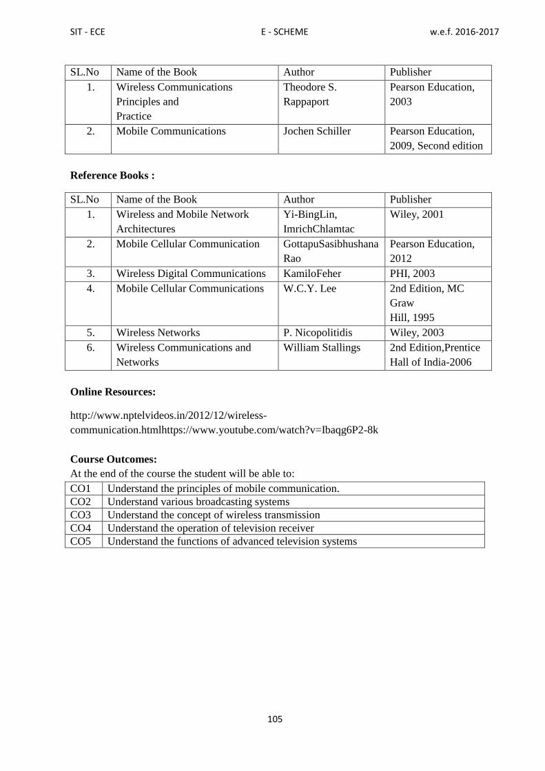
SIT - ECE E - SCHEME w.e.f. 2016-2017
105
SL.No Name of the Book Author Publisher
1. Wireless Communications
Principles and
Practice
Theodore S.
Rappaport
Pearson Education,
2003
2. Mobile Communications Jochen Schiller Pearson Education,
2009, Second edition
Reference Books :
SL.No Name of the Book Author Publisher
1. Wireless and Mobile Network
Architectures
Yi-BingLin,
ImrichChlamtac
Wiley, 2001
2. Mobile Cellular Communication GottapuSasibhushana
Rao
Pearson Education,
2012
3. Wireless Digital Communications KamiloFeher PHI, 2003
4. Mobile Cellular Communications W.C.Y. Lee 2nd Edition, MC
Graw
Hill, 1995
5. Wireless Networks P. Nicopolitidis Wiley, 2003
6. Wireless Communications and
Networks
William Stallings 2nd Edition,Prentice
Hall of India-2006
Online Resources:
http://www.nptelvideos.in/2012/12/wireless-
communication.htmlhttps://www.youtube.com/watch?v=Ibaqg6P2-8k
Course Outcomes:
At the end of the course the student will be able to:
CO1 Understand the principles of mobile communication.
CO2 Understand various broadcasting systems
CO3 Understand the concept of wireless transmission
CO4 Understand the operation of television receiver
CO5 Understand the functions of advanced television systems

SIT - ECE E - SCHEME w.e.f. 2016-2017
106
7E6405 - COMPUTER HARDWARE SERVICINGAND NETWORKING
Rationale:
Maintaining and servicing the computers, laptops and peripherals are essential
requirements of the computer students. The clear understanding of computer network
devices and protocols are also taught in this course.
Course Objectives:
The student should be made to:
Identify the components of mother board , familiar with bus standards and
memory device
Learn about various I/O device and power supply
Maintain and trouble shoot Desktops And Laptops
Understand the concept of computer networks..
Understand the different layers of OSI and their functions. Compare different
LAN protocols.
Identify the protocols used in TCP /IP and compare with OSI model. Use of IP
addressing and TCP/ IP protocols briefly.
Scheme of Instruction and Examination
7E6405 - COMPUTER HARDWARE SERVICING AND NETWORKING
Course code Instruction Examinations
7E6405
Hours/
week
Hours/
Term Credits
Marks Duration
Internal External Total 3 Hrs
5 75 5 25 75 100
UNITS - ALLOCATION OF HOURS AND MARKS
Unit no. Topics Hours Marks
I Motherboard Components And Memory Storage Devices 13 15
II I/O Devicesand Interface 13 15
III Maintenance And Trouble Shooting Of Desktop And
Laptops 13
15
IV Computer Networkdevicesand OSI Layers 13 15
V 802.XandTCP/IP Protocols 13 15
Cycle Tests, Model Exam& Revision classes
(2+2+3+3) 10
-
Total 75 75
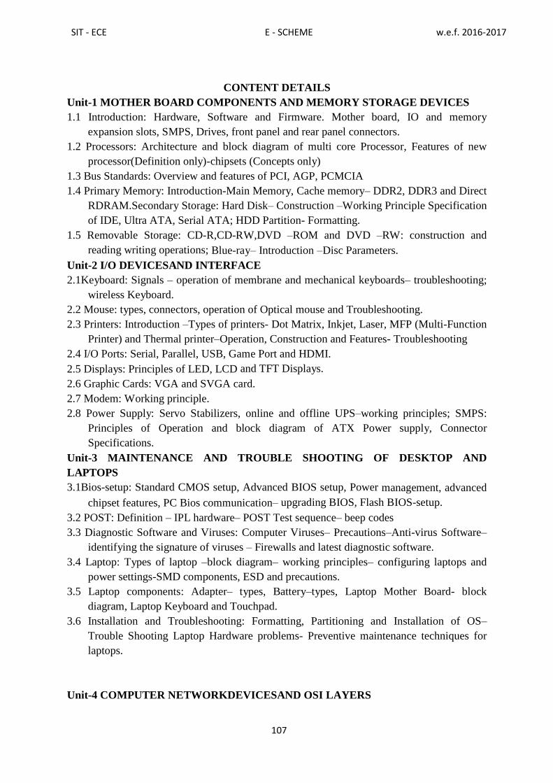
SIT - ECE E - SCHEME w.e.f. 2016-2017
107
CONTENT DETAILS
Unit-1 MOTHER BOARD COMPONENTS AND MEMORY STORAGE DEVICES
1.1 Introduction: Hardware, Software and Firmware. Mother board, IO and memory
expansion slots, SMPS, Drives, front panel and rear panel connectors.
1.2 Processors: Architecture and block diagram of multi core Processor, Features of new
processor(Definition only)-chipsets (Concepts only)
1.3 Bus Standards: Overview and features of PCI, AGP, PCMCIA
1.4 Primary Memory: Introduction-Main Memory, Cache memory– DDR2, DDR3 and Direct
RDRAM.Secondary Storage: Hard Disk– Construction –Working Principle Specification
of IDE, Ultra ATA, Serial ATA; HDD Partition- Formatting.
1.5 Removable Storage: CD-R,CD-RW,DVD –ROM and DVD –RW: construction and
reading writing operations; Blue-ray– Introduction –Disc Parameters.
Unit-2 I/O DEVICESAND INTERFACE
2.1Keyboard: Signals – operation of membrane and mechanical keyboards– troubleshooting;
wireless Keyboard.
2.2 Mouse: types, connectors, operation of Optical mouse and Troubleshooting.
2.3 Printers: Introduction –Types of printers- Dot Matrix, Inkjet, Laser, MFP (Multi-Function
Printer) and Thermal printer–Operation, Construction and Features- Troubleshooting
2.4 I/O Ports: Serial, Parallel, USB, Game Port and HDMI.
2.5 Displays: Principles of LED, LCD and TFT Displays.
2.6 Graphic Cards: VGA and SVGA card.
2.7 Modem: Working principle.
2.8 Power Supply: Servo Stabilizers, online and offline UPS–working principles; SMPS:
Principles of Operation and block diagram of ATX Power supply, Connector
Specifications.
Unit-3 MAINTENANCE AND TROUBLE SHOOTING OF DESKTOP AND
LAPTOPS
3.1Bios-setup: Standard CMOS setup, Advanced BIOS setup, Power management, advanced
chipset features, PC Bios communication– upgrading BIOS, Flash BIOS-setup.
3.2 POST: Definition – IPL hardware– POST Test sequence– beep codes
3.3 Diagnostic Software and Viruses: Computer Viruses– Precautions–Anti-virus Software–
identifying the signature of viruses – Firewalls and latest diagnostic software.
3.4 Laptop: Types of laptop –block diagram– working principles– configuring laptops and
power settings-SMD components, ESD and precautions.
3.5 Laptop components: Adapter– types, Battery–types, Laptop Mother Board- block
diagram, Laptop Keyboard and Touchpad.
3.6 Installation and Troubleshooting: Formatting, Partitioning and Installation of OS–
Trouble Shooting Laptop Hardware problems- Preventive maintenance techniques for
laptops.
Unit-4 COMPUTER NETWORKDEVICESAND OSI LAYERS
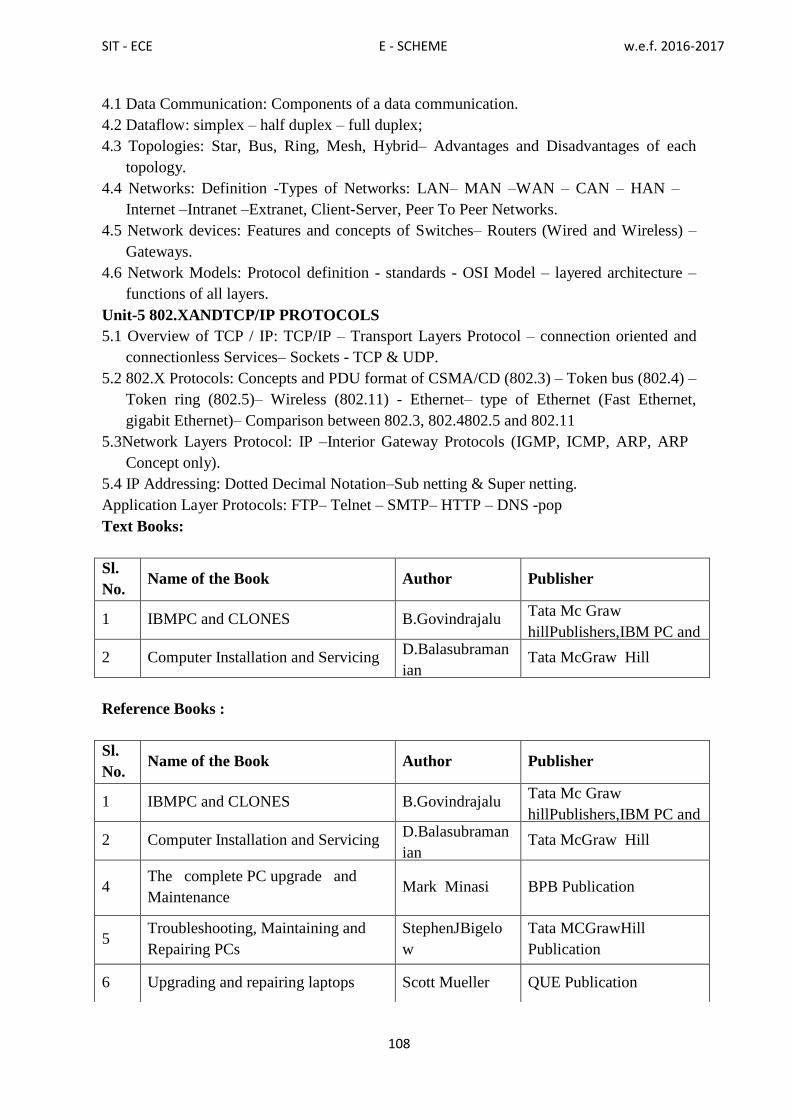
SIT - ECE E - SCHEME w.e.f. 2016-2017
108
4.1 Data Communication: Components of a data communication.
4.2 Dataflow: simplex – half duplex – full duplex;
4.3 Topologies: Star, Bus, Ring, Mesh, Hybrid– Advantages and Disadvantages of each
topology.
4.4 Networks: Definition -Types of Networks: LAN– MAN –WAN – CAN – HAN –
Internet –Intranet –Extranet, Client-Server, Peer To Peer Networks.
4.5 Network devices: Features and concepts of Switches– Routers (Wired and Wireless) –
Gateways.
4.6 Network Models: Protocol definition - standards - OSI Model – layered architecture –
functions of all layers.
Unit-5 802.XANDTCP/IP PROTOCOLS
5.1 Overview of TCP / IP: TCP/IP – Transport Layers Protocol – connection oriented and
connectionless Services– Sockets - TCP & UDP.
5.2 802.X Protocols: Concepts and PDU format of CSMA/CD (802.3) – Token bus (802.4) –
Token ring (802.5)– Wireless (802.11) - Ethernet– type of Ethernet (Fast Ethernet,
gigabit Ethernet)– Comparison between 802.3, 802.4802.5 and 802.11
5.3Network Layers Protocol: IP –Interior Gateway Protocols (IGMP, ICMP, ARP, ARP
Concept only).
5.4 IP Addressing: Dotted Decimal Notation–Sub netting & Super netting.
Application Layer Protocols: FTP– Telnet – SMTP– HTTP – DNS -pop
Text Books:
Reference Books :
Sl.
No. Name of the Book Author Publisher
1 IBMPC and CLONES B.Govindrajalu Tata Mc Graw
hillPublishers,IBM PC and
CLONES 2 Computer Installation and Servicing D.Balasubraman
ian Tata McGraw Hill
Sl.
No. Name of the Book Author Publisher
1 IBMPC and CLONES B.Govindrajalu Tata Mc Graw
hillPublishers,IBM PC and
CLONES 2 Computer Installation and Servicing D.Balasubraman
ian Tata McGraw Hill
4 The complete PC upgrade and
Maintenance Mark Minasi BPB Publication
5 Troubleshooting, Maintaining and
Repairing PCs
StephenJBigelo
w
Tata MCGrawHill
Publication
6 Upgrading and repairing laptops Scott Mueller QUE Publication

SIT - ECE E - SCHEME w.e.f. 2016-2017
109
Online Resources:
https://www.youtube.com/watch?v=hVuFOdKg1K4
https://www.youtube.com/watch?v=1eGxPllnj4M
Course Outcomes:
At the end of the course the student will be able to:
CO1 Identify and understand the major components of CPU, bus standards and memory
device
CO2 Learn about the various I/O device and power supply
CO3 Identify the bugs and trouble shoot Desktops & Laptops computer
CO4 Understand the concept of differentOSI layers and their functions. Compare different
LAN protocols.
CO5 Understand the802.x protocols used in TCP /IP and compare with OSI model.
Use of IP addressing
7 Data Communication and
networking
BehrouzA.Forou
zan
TataMc-Graw Hill,
NewDelhi
8 Data and Computer Communications WilliamStallings Prentice-Hallof India,
Eighth Edition
9 Computer Networks
AndrewS.Tanen
baum
Prentice-Hall ofIndia,
New
Delhi

SIT - ECE E - SCHEME w.e.f. 2016-2017
110
7E6315 - EMBEDDED SYSTEMS LAB
RATIONALE:
ARM is a major processor widely used in the embedded system in products ranging
from cell/mobile phones to automotive braking and control systems. Since 1985, the ARM
architecture has become the most pervasive 32-bit architecture in the world. This practical
course has been set up to describe the operation of the ARM core from experimenting simple
exercises with a clear emphasis on its architecture by assuming no previous ARM
experience. In Diploma level, the ARM architecture is studied and experimented for its
internals through hands on. This is achieved by experiencing the experiments through
industrial and society needs. Also this practical course makes the students to get acquainted
with embedded c program, ability to describe the system requirement and to make a
complete prototype working model.
Course Objectives:
Develop an assembly level code for basic arithmetic primitive operations
Develop an assembly level code in both ARM and THUMB instructions.
Develop an embedded c program for input and output operations.
Develop an embedded c program for special functions.
Develop an assembly level and embedded c code for interface and other
applications
Develop simple application in RTOS
Scheme of Instruction and Examination
SCHEME OF EVALUATION
SL.NO DESCRIPTION MARKS
1 PROGRAM 30
2 EXECUTION 30
3 RESULT 10
4 VIVA–VOCE 05
5 TOTAL 75
Course code Instruction Examinations
7E6315
Hours/ week Hours/
Term Credits
Marks Duration
Internal External Total
3 Hrs Tutorial practical 75 3 25 75 100
1 4
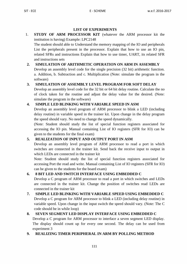
SIT - ECE E - SCHEME w.e.f. 2016-2017
111
LIST OF EXPERIMENTS
1. STUDY OF ARM PROCESSOR KIT (whatever the ARM processor kit the
institution is having) Example: LPC2148
The student should able to Understand the memory mapping of the IO and peripherals
List the peripherals present in the processor. Explain that how to use an IO pin,
related SFRs and instructions Explain that how to use timer, UART, its related SFR
and instructions sets
2. SIMULATION OF ARITHMETIC OPERATION ON ARM IN ASSEMBLY
Develop an assembly level code for the single precision (32 bit) arithmetic function.
a. Addition, b. Subtraction and c. Multiplication (Note: simulate the program in the
software)
3. SIMULATION OF ASSEMBLY LEVEL PROGRAM FOR SOFT DELAY
Develop an assembly level code for the 32 bit or 64 bit delay routine. Calculate the no
of clock taken for the routine and adjust the delay value for the desired. (Note:
simulate the program in the software)
4. SIMPLE LED BLINKING WITH VARIABLE SPEED IN ASM
Develop an assembly level program of ARM processor to blink a LED (including
delay routine) in variable speed in the trainer kit. Upon change in the delay program
the speed should vary. No need to change the speed dynamically.
(Note: Student should study the list of special function registers associated for
accessing the IO pin. Manual containing List of IO registers (SFR for IO) can be
given to the students for the final exam)
5. REALIZATION OF INPUT AND OUTPUT PORT IN ASM
Develop an assembly level program of ARM processor to read a port in which
switches are connected in the trainer kit. Send back the receive input to output in
which LEDs are connected in the trainer kit
Note: Student should study the list of special function registers associated for
accessing Port the read and write. Manual containing List of IO registers (SFR for IO)
can be given to the students for the board exam)
6. 8 BIT LED AND SWITCH INTERFACE USING EMBEDDED C
Develop a C program of ARM processor to read a port in which switches and LEDs
are connected in the trainer kit. Change the position of switches read LEDs are
connected in the trainer kit
7. SIMPLE LED BLINKING WITH VARIABLE SPEED USING EMBEDDED C
Develop a C program for ARM processor to blink a LED (including delay routine) in
variable speed. Upon change in the input switch the speed should vary. (Note: The C
code should be in while loop)
8. SEVEN SEGMENT LED DISPLAY INTERFACE USING EMBEDDED C
Develop a C program for ARM processor to interface a seven segment LED display.
The display should count up for every one second. The delay can be used from
experiment 3
9. REALIZING TIMER PERIPHERAL IN ARM BY POLLING METHOD

SIT - ECE E - SCHEME w.e.f. 2016-2017
112
Develop a C program for ARM processor to run a timer peripheral in ARM. The timer
flag can be Pooled for timer end. As timer ends reset the timer and update new value to
the LED display.
10. SEVEN SEGMENT LED DISPLAY INTERFACE USING EMBEDDED C
Develop a C program for ARM processor to interface a seven segment LED display.
The display should count up for every one second. The delay can be used from
experiment 3
11. SERIAL TRANSMISSION AND RECEPTION OF A CHARACTER USING
EMBEDDED C BY INTERRUPT METHOD
Write a C Programs for receiving a character from other device (Computer) and send
the next character of the received one to the device back.
12. DISPLAYING ALPHANUMERIC CHARACTERS IN 2X16 LINE LCD
MODULE
Write a C Programs for displaying a number and an alphabet in the LCD module by
just calling the built in LCD function. The display should come in the desired line and
column. (Built in function for the LCD can be given in the manual)
13. CONVERTING HEXADECIMAL TO DECIMAL AND TO DISPLAY IN LCD
Write a C Programs for converting the given 8 bit hexadecimal into decimal and there
by converting into ASCII which is to be displayed in the LCD module.(Built in
function for the LCD can be given in the manual)
14. ACCESSING INTERNAL ADC OF THE ARM PROCESSOR AND TO
DISPLAY IN LCD
Write a C Programs for reading an ADC, convert into decimal and to display it. The
ADC input is connected to any analog sensor. (Note: Student should study the SFR
associated with ADC, Manual containing List of SFR for accessing ADC can be given
for the examination.)
15. INTERFACING BUZZER AND RELAY IN ARM PROCESSOR
Develop a C program for ARM processor to interface a Buzzer and Relay
HARDWAREREQUIREMENT:
ARM7TDMIKit -10 Nos
(Includes Buzzer, Relay, RTC,
ADC,LCD,Sevensegmentdisplay,LEDSandSwitches, Stepper motor,
Temperature sensor and RS 232 – C)
PC with Keyboard -20 Nos
SOFTWAREREQUIREMNT:
Triton (Debugger / Compiler)
Course Outcomes:
At the end of the course the student will be able to:
CO1 Write assembly language programs
CO2 Develop an embedded c program for input and output operations
CO3 Develop simple application in RTOS

SIT - ECE E - SCHEME w.e.f. 2016-2017
113
7E6316 - INDUSTRIAL ELECTRONICS AND PLC LAB
Rationale:
This lab provides the students the complete knowledge of the power electronic devices and
circuits used in modern industry for conversion of power. The lab helps the students to
analyze the characteristics of power devices and understand the applications of PLC.
Course Objectives:
After completion of this lab, the students will be able to
Analyze the characteristics of power devices.
Construct and test the applications of power devices.
Write and implement ladder diagrams for PLC.
Scheme of Instruction and Examination
SCHEME OF EVALUATION
SL.NO DESCRIPTION MARKS
1. CIRCUITDIAGRAM 20
2. CONNECTION 25
3. EXECUTION 15
4. RESULT & GRAPH 10
5. VIVA–VOCE 05
6. TOTAL 75
LIST OF EXPERIMENTS
1. Determine the phase control characteristics of SCR.
2. Construct and test a Line synchronized, Ramp and Pedestal UJT trigger circuit with AC
load
3. Construct and test a Lamp control circuit using DIAC – TRIAC
4. Construct and test a Single phase Half Controlled Bridge with R load.
5. Construct and test a Single phase Fully Controlled Bridge with R load.
6. Construct and test a Basic Series Inverter circuit
7. Construct and test a MOSFET based PWM chopper circuit.
Course code Instruction Examinations
7E3201
Hours/
week
Hours/
Term Credits
Marks Duration
Internal External Total 3 Hrs
6 90 3 25 75 100

SIT - ECE E - SCHEME w.e.f. 2016-2017
114
8. Construct and test commutation circuits of SCR.
9. Construct and test a Single phase Parallel Inverter using MOSFET / IGBT.
10. Construct and test an IC based buck converter using PWM.
11. Write and implement a simple ladder logic program using digital inputs and outputs for
PLC.
12. Write and implement a simple ladder logic program using on timer and off timer with
branching and subroutines with PLC.
13. Write and implement a simple ladder logic program using counter with branching and
subroutines with PLC.
14. Write and implement a simple ladder logic program for interfacing a lift control with
PLC.
15. Write and implement a simple ladder logic program for interfacing a conveyor control
with PLC.
MAJOR EQUIPMENTS REQUIRED:
S.NO NameoftheEquipment Range RequiredNos.
1. DualtraceCRO 30MHz 7
2. Phase control of SCR Kit 1
3. UJT Triggering Kit 1
4. Lamp control using DIAC – Triac Kit 1
5. Single phase half controlled with R Load
Kit 1
6. Single phase full controlled with R Load Kit 1
7. Basic series Inverter Kit 1
8. Parallel Inverter Kit 1
9. MOSFET Based PWM Chopper kit 1
10. SCR Commutation Kit 1
11. Buck Converter kit 1
12. PLC Trainer kit 2
13. PC 2
14. Lift working model 1
15. Conveyor working model 1
Course Outcomes:
At the end of the course the student will be able to:
CO1 Understand the characteristics of power devices
CO2 Construct and test the performance of applications of power devices
CO3 Understand PLC and write ladder diagram for specific applications

SIT - ECE E - SCHEME w.e.f. 2016-2017
115
7E6406 - COMPUTER HARDWARE SERVICING AND NETWORKING LAB
Rationale:
The course aims at making the students familiar with various parts of computers and
laptops and how to assemble them and the different types of peripherals desired. In addition,
the course will provide the students with necessary knowledge and skills in computer and
laptop software installation and maintenance and to make him diagnose the software faults.
This course also gives the knowledge and competency to diagnose the problems in computer
hardware and peripherals and also gives the knowledge for trouble shooting, for systematic
repair and maintenance of computers and laptops
Course Objectives:
On completion of the following exercises, the students must be able to
Know the various indicators, switches and connectors used in Computers.
Familiarize the layout of SMPS, motherboard and various Disk Drives.
Configure Bios set up options.
Install various secondary storage devices with memory partition and
formatting.
Know the various types of printer installation and to handle the
troubleshooting ability.
Acquire the practical knowledge about the installation of various devices
like scanner, web camera, cell phone and bio-metric devices.
Assemble PC system and checking the working condition.
Installation of Dual OS in a system.
Identify the problems in Computer systems, software installation and
rectification also.
Assembling and disassembling of Laptop to identify the parts and to install
OS and configure it.
Enable to perform different cabling in a network.
Configure Internet connection and use utilities to debug the network
issues.
Configure router for any topology
Course code Instruction Examinations
7E6406
Hours/ week Hours/
Term Credits
Marks Duration
Internal External Total
3 Hrs Tutorial practical 75 3 25 75 100
1 4
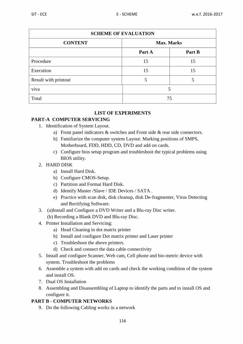
SIT - ECE E - SCHEME w.e.f. 2016-2017
116
SCHEME OF EVALUATION
CONTENT Max. Marks
Part A Part B
Procedure 15 15
Execution 15 15
Result with printout 5 5
viva 5
Total 75
LIST OF EXPERIMENTS
PART-A COMPUTER SERVICING
1. Identification of System Layout.
a) Front panel indicators & switches and Front side & rear side connectors.
b) Familiarize the computer system Layout: Marking positions of SMPS,
Motherboard, FDD, HDD, CD, DVD and add on cards.
c) Configure bios setup program and troubleshoot the typical problems using
BIOS utility.
2. HARD DISK
a) Install Hard Disk.
b) Configure CMOS-Setup.
c) Partition and Format Hard Disk.
d) Identify Master /Slave / IDE Devices / SATA .
e) Practice with scan disk, disk cleanup, disk De-fragmenter, Virus Detecting
and Rectifying Software.
3. (a)Install and Configure a DVD Writer and a Blu-ray Disc writer.
(b) Recording a Blank DVD and Blu-ray Disc.
4. Printer Installation and Servicing:
a) Head Cleaning in dot matrix printer
b) Install and configure Dot matrix printer and Laser printer
c) Troubleshoot the above printers.
d) Check and connect the data cable connectivity
5. Install and configure Scanner, Web cam, Cell phone and bio-metric device with
system. Troubleshoot the problems
6. Assemble a system with add on cards and check the working condition of the system
and install OS.
7. Dual OS Installation
8. Assembling and Disassembling of Laptop to identify the parts and to install OS and
configure it.
PART B - COMPUTER NETWORKS
9. Do the following Cabling works in a network

SIT - ECE E - SCHEME w.e.f. 2016-2017
117
(a)Cable Crimping b) Standard Cabling c ) Cross Cabling d) IO connector crimping
e) Testing the crimped cable using a cable tester
10. Configure Host IP, Subnet Mask and Default Gateway in a system in LAN (TCP/IP
Configuration).Configure Internet connection and use IPCONFIG, PING / Tracert
and Netstat utilities to debug the network issues
11. Interface two PCs using Peer To Peer network using connectivity devices – Switch
and Router in a LAN and share the Drives and Folders.
12. Transfer files between systems in LAN using FTP Configuration, install Print server
in a LAN and share the printer in a network.
13. Configure DNS to establish interconnection between systems and describe how a
name is mapped to IP Address
14. Install and configure Network Devices: HUB, Switch and Routers
15. Install and Configure Wired and Wireless NIC and transfer files between systems in
LAN and Wireless LAN
PARTA–COMPUTERSERVICINGPRACTICAL
1. Hardware Requirements:
ComputerwithPentium/Core processorswithaddoncards -20 Nos
Harddiskdrive -06Nos
CDDrive -06Nos
DVDWriter -06Nos
BlankDVD - 20Nos
BlankBlue-raydisk - 20Nos
HeadcleaningCD
DotmatrixPrinter - 03Nos
LaserPrinter - 03 Nos
DigitalCamera -01Nos
WebCamera -01Nos
Scanner -02Nos
Bluetoothdeviceandcellphone -02Nos
Bio-metricdevice -02Nos
Laptop -20Nos
2. SoftwareRequirements: WindowsXPoperatingsystem
Linuxoperatingsystem
DiskManager(forthepurposeofpartitionandformat) NortonorE-TrustAntivirussoftware
Scandisk
DVDWriterS/W
CDBurningS/W(AheadNeroorlatestS/W)
Blue-rayBurningS/W
PARTB–COMPUTERNETWORKPRACTICAL 1. ToolsRequirement
CrimpingTool -06Nos
NetworkCables 2. EquipmentRequirement
Modem -01No

SIT - ECE E - SCHEME w.e.f. 2016-2017
118
LaserPrinter -01No
Hub -01No
Router -01No
Switch -01No
3. SystemRequirement Pentium SystemsWithonboardEthernetCard(NIC) -36Nos
4. SoftwareRequirement
Windows2007or2008 orLINUXServer.DriversSoftware
Course Outcomes:
At the end of the course the student will be able to:
CO1 Understand the operating systems
CO2 Understand the functions of various parts CPU and debug
CO3 Understand computers and protocols

SIT - ECE E - SCHEME w.e.f. 2016-2017
119
7E6317 - PROJECT WORK
Course Objectives:
The project is aimed to assemble test a photo type model of any one item/gadget
Real time application problems if any may be identified from any industry and maybe
chosen
The knowledge and the skill sofar acquired may be made use of.
The team spirit may be motivated
The entrepreneurship ideas may be motivated by conducting a career guidance
programme
Learn and understand the gap between the technological knowledge acquired through
curriculum and the actual industrial need and to compense it by acquiring additional
knowledge as required
Scheme of Instruction and Examination
ENVIRONMENTAL STUDIES& DISASTER MANAGEMENT
CONTENT DETAILS
1. ENVIRONMENTAL STUDIES
1.1 Introduction – Environmental Ethics – Assessment of Socio Economic Impact –
Environmental Audit – Mitigation of adverse impact on Environment – Importance of
Pollution Control – Types of Industries and Industrial Pollution.
1.2 Solid waste management – Characteristics of Industrial wastes – Methods of
Collection, transfer and disposal of solid wastes – Converting waste to energy – Hazardous
waste management Treatment technologies.
1.3 Waste water management – Characteristics of Industrial effluents –Treatment and
disposal methods – Pollution of water sources and effects on human health.
1.4 Air pollution management – Sources and effects – Dispersion of air pollutants –
Air pollution control methods – Air quality management.
Course code Instruction Examinations
7E6317
Hours/
week
Hours/
Term Credits
Marks Duration
Internal External Total 3 Hrs
4 60 2 25 75 100

SIT - ECE E - SCHEME w.e.f. 2016-2017
120
1.5 Noise pollution management – Effects of noise on people – Noise control
methods.
2. DISASTER MANAGEMENT
2.1 Introduction – Disasters due to natural calamities such as Earthquake, Rain,
Flood, Hurricane, Cyclones etc – Man made Disasters – Crisis due to fires, accidents, strikes
etc – Loss of property and life..
2.2 Disaster Mitigation measures – Causes for major disasters – Risk Identification –
Hazard Zones – Selection of sites for Industries and residential buildings – Minimum
distances from Sea – Orientation of Buildings – Stability of Structures – Fire escapes in
buildings – Cyclone shelters – Warning systems.
2.3 Disaster Management – Preparedness, Response, Recovery –
Arrangements to be made in the industries / factories and buildings – Mobilization of
Emergency Services - Search and Rescue operations –
First Aids – Transportation of affected people – Hospital facilities – Fire fighting
arrangements – Communication systems – Restoration of Power supply – Getting assistance
of neighbors / Other organizations in Recovery and Rebuild I n works – Financial
commitments – Compensations to be paid – Insurances – Rehabilitation.
LIST OF QUESTIONS
ENVIRONMENTRAL STUDIES
1. What is the responsibility of an Engineer-in-charge of an Industry with respect to Public
Health?
2. Define Environmental Ethic.
3. How Industries play their role in polluting the environment?
4. What is the necessity of pollution control? What are all the different organizations you
know, which deal with pollution control?
5. List out the different types of pollutions caused by a Chemical / Textile / Leather /
Automobile / Cement factory.
6. What is meant by Hazardous waste?
7. Define Industrial waste management.
8. Differentiate between garbage, rubbish, refuse and trash based on their composition and
source.
9. Explain briefly how the quantity of solid waste generated in an industry could be reduced.
10. What are the objectives of treatments of solid wastes before disposal?
11. What are the different methods of disposal of solid wastes?
12. Explain how the principle of recycling could be applied in the process of waste
minimization.
13. Define the term „Environmental Waste Audit‟.
14. List and discuss the factors pertinent to the selection of landfill site.
15. Explain the purpose of daily cover in a sanitary landfill and state the minimum desirable
depth of daily cover.
16. Describe any two methods of converting waste into energy.

SIT - ECE E - SCHEME w.e.f. 2016-2017
121
17. What actions, a local body such as a municipality could take when the agency appointed
for collecting and disposing the solid wastes fails to do the work continuously for number of
days?
18. Write a note on Characteristics of hazardous waste.
19. What is the difference between municipal and industrial effluent ?
20. List few of the undesirable parameters / pollutants anticipated in the effluents from oil
refinery industry / thermal power plants / textile industries / woolen mills / dye industries /
electroplating industries / cement plants / leather industries (any two may be asked)
21. Explain briefly the process of Equalization and Neutralization of waste water of varying
characteristics discharged from an Industry.
22. Explain briefly the Physical treatments “Sedimentation” and “Floatation” processes in
the waste water treatment.
23. Explain briefly when and how chemical / biological treatments are given to the waste
water.
24. List the four common advanced waste water treatment processes and the pollutants they
remove.
25. Describe refractory organics and the method used to remove them from the effluent.
26. Explain biological nitrification and de-nitrification.
27. Describe the basic approaches to land treatment of Industrial Effluent.
28. Describe the locations for the ultimate disposal of sludge and the treatment steps needed
prior to ultimate disposal.
29. List any five Industries, which act as the major sources for Hazardous Air Pollutants.
30. List out the names of any three hazardous air pollutants and their effects on human
health.
31. Explain the influence of moisture, temperature and sunlight on the severity of air
pollution effects on materials.
32. Differentiate between acute and chronic health effects from Air pollution.
33. Define the term Acid rain and explain how it occurs.
34. Discuss briefly the causes for global warming and its consequences
35. Suggest suitable Air pollution control devices for a few pollutants and sources.
36. Explain how evaporative emissions and exhaust emissions are commonly controlled.
37. What are the harmful elements present in the automobile smokes? How their presence
could be controlled?
38. What is the Advantage of Ozone layer in the atmosphere? State few reasons for its
destruction.
39. Explain the mechanism by which hearing damage occurs.
40. List any five effects of noise other than hearing damage.
41. Explain why impulsive noise is more dangerous than steady state noise.
42. Explain briefly the Source – Path – Receiver concept of Noise control.
43. Where silencers or mufflers are used ? Explain how they reduce the noise.
44. Describe two techniques to protect the receiver from hearing loss when design / redress
for noise control fail.
45. What are the problems faced by the people residing along the side of a railway track and
near to an Airport? What provisions could be made in their houses to reduce the problem?

SIT - ECE E - SCHEME w.e.f. 2016-2017
122
2. DISASTER MANAGEMENT
1. What is meant by Disaster Management? What are the different stages of Disaster
management?
2. Differentiate Natural Disasters and Man made Disasters with examples.
f3. Describe the necessity of Risk identification and Assessment Surveys while planning a
project.
4. What is Disasters recovery and what does it mean to an Industry?
5. What are the factors to be considered while planning the rebuilding works after a major
disaster due to flood / cyclone / earthquake? (Any one may be asked)
6. List out the public emergency services available in the state, which could be approached
for help during a natural disaster.
7. Specify the role played by an Engineer in the process of Disaster management.
8. What is the cause for Earthquakes? How they are measured? Which parts of India are
more vulnerable for frequent earthquakes?
9. What was the cause for the Tsunami 2004 which inflicted heavy loss to life and property
along the coast of Tamilnadu ? Specify its epicenter and magnitude.
10. Specify the Earthquake Hazard Zones in which the following towns of Tamilnadu lie: (a)
Chennai (b) Nagapattinam (c) Coimbatore (d) Madurai (e) Salem.
11. Which parts of India are experiencing frequent natural calamities such as (a) heavy rain
fall (b) huge losses due to floods (c) severe cyclones
12. Define basic wind speed. What will be the peak wind speed in (a) Very high damage risk
zone – A, (b) High damage risk zone, (c) Low damage risk zone.
13. Specify the minimum distance from the Sea shore and minimum height above the mean
sea level, desirable for the location of buildings.
14. Explain how the topography of the site plays a role in the disasters caused by floods and
cyclones.
15. Explain how the shape and orientation of buildings could reduce the damages due to
cyclones.
16. What is a cyclone shelter ? When and where it is provided ? What are its requirements ?
17. What Precautionary measures have to be taken by the authorities before opening a dam
for discharging the excess water into a canal/river ?
18. What are the causes for fire accidents ? Specify the remedial measures to be taken in
buildings to avoid fire accidents.
19. What is a fire escape in multistoried buildings ? What are its requirements ?
20. How the imamates of a multistory building are to be evacuted in the event of a
fire/Chemical spill/Toxic Air Situation/ Terrorist attack, (any one may be asked).
21. Describe different fire fighting arrangements to be provided in an Industry.
22. Explain the necessity of disaster warning systems in Industries.
23. Explain how rescue operations have to be carried out in the case of collapse of buildings
due to earthquake / blast / Cyclone / flood.

SIT - ECE E - SCHEME w.e.f. 2016-2017
123
24. What are the necessary steps to be taken to avoid dangerous epidemics after a flood
disaster?
25. What relief works that have to be carried out to save the lives of workers when the
factory area is suddenly affected by a dangerous gas leak / sudden flooding ?
26. What are the difficulties faced by an Industry when there is a sudden power failure? How
such a situation could be managed?
27. What are the difficulties faced by the Management when there is a group clash between
the workers? How such a situation could be managed?
28. What will be the problems faced by the management of an Industry when a worker dies
because of the failure of a mechanical device due to poor maintenance? How to manage such
a situation ?
29. What precautionary measures have to be taken to avoid accidents to labourers in the
Industry in a workshop / during handling of dangerous Chemicals / during construction of
buildings / during the building maintenance works.
30. Explain the necessity of medical care facilities in an Industry / Project site.
31. Explain the necessity of proper training to the employees of Industries dealing with
hazardous products, to act during disasters.
32. What type of disaster is expected in coal mines, cotton mills, Oil refineries, ship yards
and gas plants?
33. What is meant by Emergency Plan Rehearsal? What are the advantages of such
Rehearsals?
34. What action you will take when your employees could not reach the factory site because
of continuous strike by Public Transport workers?
35. What immediate actions you will initiate when the quarters of your factory workers are
suddenly flooded due to the breach in a nearly lake / dam, during heavy rain?
36. What steps you will take to avoid a break down when the workers union of your Industry
have given a strike notice?
37. List out few possible crisis in an organization caused by its workers? What could be the
part of the middle level officials in managing such crisis?
38. What types of warning systems are available to alert the people in the case of predicted
disasters, such as floods, cyclone etc.
39. Explain the necessity of Team work in the crisis management in an Industry / Local
body.
40. What factors are to be considered while fixing compensation to the workers in the case
of severe accidents causing disability / death to them?
41. Explain the legal / financial problems the management has to face if safely measures
taken by them are found to be in adequate.
42. Describe the importance of insurance to men and machinery of an Industry dealing with
dangerous jobs.
43. What precautions have to be taken while storing explosives in a match/ fire crackers
factory?
44. What are the arrangements required for emergency rescue works in the case of Atomic
Power Plants?
45. Why residential quarters are not constructed nearer to Atomic Power Plants?

SIT - ECE E - SCHEME w.e.f. 2016-2017
124
MODEL QUESTION PAPERS

SIT - ECE E - SCHEME w.e.f. 2016-2017
125
SESHASAYEE INSTITUTE OF TECHNOLOGY: TRICHY -10.
Model Question Paper
E – Scheme
[Note: Compulsory questions : Part A No. :8 & Part B No. : 16]
Term : IIIECE Time : 3 Hours
Course: ELECTRONIC DEVICES AND ITS APPLICATIONS Max. Mark: 75
PART – A
Answer any FIVE from the following ( 5 x 2 =10)
1. What are the types of extrinsic semiconductor?
2. Define rectifier and mention its applications.
3. What is clamper and mention its types.
4. Define: LED.
5. Draw the symbols of NPN and PNP transistors and name the terminals.
6. State barkhausencriterian.
7. Draw the symbol N channel FET and name the terminals.
8. What are the three types of Multivibrator?
PART – B
Answer any FIVE from the following : ( 5 x 3 =15)
9 Explain zener breakdown and avalanche breakdown.
10 Explain LC filter
11 Explain positive feedback and negative feedback.
12 Explain the operation of tank circuit used in oscillators.
13 Explain the operation of MOSFET used as a switch.
14 Explain the equivalent circuit of UJT.
15 Explain about the VI characteristics of SCR.
16 Draw the circuit diagram and waveforms of Bistablemultivibrator.
.
PART – C
Answer all the questions by choosing either (a),(b) or (c) of each question :(5x10 =50)
17. (A) Explain the working of a PN diode under forward and reverse biased condition.
( OR )
(B) Explain the working of zener as a voltage regulator.
18. (A) Explain the working of Full wave rectifier with its circuit diagram and waveform.
( OR )
(B) Explain the working of combination clipper with its circuit diagram.
.
19. (A) Explain the working of RC coupled amplifier with its circuit diagram.
( OR )
(B) Explain the working of RC phase shift oscillator. What is the formula for frequency
of oscillations?

SIT - ECE E - SCHEME w.e.f. 2016-2017
126
20. (A) Explain the drain and transfer characteristics of a JFET.
( OR )
(B) Explain the construction and working of depletion mode N channel MOSFET.
Draw its transfer characterisitics.
21. (A) Explain the working of a controlled rectifier using SCR. Draw the relevant
waveforms.
( OR )
(B) Explain the working of astablemultivibrator with relevant waveforms.
*********************

SIT - ECE E - SCHEME w.e.f. 2016-2017
127
SESHASAYEE INSTITUTE OF TECHNOLOGY: TRICHY -10.
Model Question Paper
E – Scheme
[Note: Compulsory questions : Part A No. :8 & Part B No. : 16]
Term : IIIECE Time : 3 Hours
Course:ELECTRICAL CIRCUITS AND INSTRUMENTATIONMax. Mark: 75
PART - A
Answer any FIVE from the following ( 5 x 2 =10)
1. Define resistance.
2. State the unit of power and energy.
3. Define impedance.
4. Define bandwidth.
5. Define transformer.
6. Define DC generator.
7. What are the types of basic forces required for the indicating instruments?
8. What is meant by transducer?
PART – B
Answer any FIVE from the following : ( 5 x 3 =15)
9. Find the equivalent resistance when two resistances are connected in parallel.
10. Draw Norton‟s equivalent circuit.
11. Draw RC series circuit and corresponding vector diagram.
12. What are the applications of resonance.
13. What are the various types of dc generator?
14. What are the applications of stepper motor?
15. State the advantages of PMMC instrument.
16. State the types of transducers
PART – C
Answer all the questions by choosing either (a),(b) or (c) of each question :(5x10 =50)
17. (A) State and explain kirchoff‟s laws.
(OR)
(B ) State and explain thevenin‟s theorem.
18. (A) Derive an expression for the impedance in an R-L series circuit.
(OR)
(B) Derive an expression for the resonant frequency and Q factor of a series resonant
circuit.
19. (A) Derive the e.m.f. equation of a transformer.
(OR)
(B) Explain the working of capacitor start induction motor.
20. (A) Explain with diagram the construction and working of PMMC instrument.

SIT - ECE E - SCHEME w.e.f. 2016-2017
128
(OR)
(B) Draw the block diagram of CRO and explain its operation.
21. (A) Explain the construction and working of Load cell.
(OR)
(B) Explain the working of digital multimeter with a block diagram.
**************************

SIT - ECE E - SCHEME w.e.f. 2016-2017
129
SESHASAYEE INSTITUTE OF TECHNOLOGY:: TRICHY -10.
Model Question Paper
E – Scheme
[Note: Compulsory questions : Part A No. :8 & Part B No. : 16]
Term : IIIECE Time : 3 Hours
Course: C - PROGRAMMING Max. Mark: 75
PART - A
Answer any FIVE from the following ( 5 x 2 =10)
1. Define program ?
2. What are the fundamental data types ?
3. What are the types of if statements ?
4. Why the break statement is used ?
5. Define array ?
6. What is the meaning of strcat ( ) and strcmp ( ) ?
7. Give any 2 differences between union and structure ?
8. What is known as dynamic memory allocation ?
PART – B
Answer any FIVE from the following : ( 5 x 3 =15)
9. Give any 3 comparison between the types of programming languages.?
10. Give any 3 features of C - language.?
11. Give general Syntax to declare a variable ?
12. What are the different types of C - operators ?
13. Give general Syntax to declare two dimensional array ?
14. Give general Syntax to declare a structure ?
15. What is recursion ?
16. When and Why the function MALLOC and CALLOC is used ?
PART – C
Answer all the questions by choosing either (a),(b) or (c) of each question :(5x10 =50)
17) A) Explain about the Program development cycle ?
( OR )
B) Explain about the identifiers and variables ?
18) A) Explain about the arithmetic, logical, relational, bitwise operators?
( OR )
B) Explain about the While and Do while statements?
19) A) Explain about the declaration & initialization of 2-dimensional array?
( OR )

SIT - ECE E - SCHEME w.e.f. 2016-2017
130
B) Explain about the different string handling functions with an example?
20) A) Explain about the structure with an example ?
( OR )
B) Explain about the different memory allocation functions ?
21) A) Write a program to Swap the values of two variables ?
( OR )
B) Write a program to find Resonant frequency of RLC circuit ?

SIT - ECE E - SCHEME w.e.f. 2016-2017
131
SESHASAYEE INSTITUTE OF TECHNOLOGY:: TRICHY -10.
Model Question Paper
E – Scheme
[Note: Compulsory questions : Part A No. :8 & Part B No. : 16]
Term : IVECE Time : 3 Hours
Course: ELECTRONIC CIRCUITS Max. Mark: 75
PART - A
Answer any FIVE from the following ( 5 x 2 =10)
1. Define: Operating point
2. What is the need for multi stage amplifier?
3. What is heat sink?
4. What are the types of feedback amplifiers?
5. What are the two conditions for oscillation?
6. What is the frequency of oscillation for wien bridge oscillator?
7. What are the types of voltage regulator?
8. Draw the block diagram of SMPS.
PART – B
Answer any FIVE from the following : ( 5 x 3 =15)
9. Explain about transistor biasing.
10. What is thermal runaway?
11. What is power transistor?
12. What are the application of power amplifiers?
13. Draw the circuit diagram of common source amplifier.
14. What is meant by barkhausencriterian?
15. Draw the circuit diagram of negative resistance oscillator.
16. Write about 78XX and 79XX IC Regulator.
PART – C
Answer all the questions by choosing either (a),(b) or (c) of each question :(5x10 =50)
17. (A) Explain the operation of Emitter follower with circuit diagram .
( OR )
(B) Explain about DC and AC load line with diagram.
18. (A) Explain any two feedback amplifiers with block diagram..
( OR )
(B Explain the operation of Class A amplifier.
19. (A) Explain the operation of CS and CG amplifiers with neat diagram.
( OR )

SIT - ECE E - SCHEME w.e.f. 2016-2017
132
(B) Explain the operation of Zero bias for D MOSFET.
20. (A) Explain the operation of tuned collector oscillator with circuit diagram.
( OR )
(B) Explain the operation of wien bridge oscillator.
21. (A) Explain the operation of transistorized series feedback type regulator.
( OR )
(B) Explain the operation of SMPS with its block diagram.

SIT - ECE E - SCHEME w.e.f. 2016-2017
133
SESHASAYEE INSTITUTE OF TECHNOLOGY:: TRICHY -10.
Model Question Paper
E – Scheme
[Note: Compulsory questions : Part A No. :8 & Part B No. : 16]
Term : IVECE Time : 3 Hours
Course: COMMUNICATION ENGINEERING Max. Mark: 75
PART - A
Answer any FIVE from the following ( 5 x 2 =10)
1. Draw the wave form of PAM
2. What is antenna?
3. What is the use of AGC
4. List the disadvantage of TRF
5. List anyone electrical characteristics of symmetrical network
6. What is a micro phone?
7. Define aspect ratio
8. Define frequency
PART – B
Answer any FIVE from the following : ( 5 x 3 =15)
9. List the types of modulation
10. What is the difference between high and low level modulation?
11. Write short notes on VSB
12. Compare AM and FM
13. Draw the equivalent diagram of transmission line
14. List down the applications of Equaliser
15. Write short notes on DTS
16. Why modulation is required?
PART – C
Answer all the questions by choosing either (a),(b) or (c) of each question :(5x10 =50)
17. (A) With a neat sketch explain how beam width of antenna is measured
OR
(B) Explain in detail the ionosphere layer of sky wave propagation
18. (A) Explain how transmitters are classified
OR
(B) Explain the SHD receiver with neat diagram

SIT - ECE E - SCHEME w.e.f. 2016-2017
134
19. (A) Explain indirect method of FM generation with neat diagram
OR
(B) Compare PAM,PWM,PPM
20. (A) Explain the primary constants of transmission line
OR
(B) Derive an expression for cut off frequency of a constant k low pass filter
21. (A) Explain the operation of CARBON micro-phone
OR
(B) Explain with diagram the operation of CCTV
SIT - ECE E - SCHEME w.e.f. 2016-2017
135
SESHASAYEE INSTITUTE OF TECHNOLOGY:: TRICHY -10.
Model Question Paper
E – Scheme
[Note: Compulsory questions : Part A No. :8 & Part B No. : 16]
Term : IVECE Time : 3 Hours
Course: DIGITAL ELECTRONICS Max. Mark: 75
PART - A
Answer any FIVE from the following ( 5 x 2 =10)
1. Define: Binary and octal number system.
2. Define: Demorgan‟s theorem.
3. Define: Signed binary number
4. Define: Parity bit and mention its uses.
5. Define the NO change and toggle conditions of flip flop.
6. Define: Decade counter and MOD N counter
7. Expand EEPROM and DDR RAM
8. Define: Interrupt signal and mention its types.
PART – B
Answer any FIVE from the following : ( 5 x 3 =15)
9. Explain the rolling techniques used in Karnaugh map with example.
10. Simplify the Boolean expression of f( A,B,C,D) = ∑ (4,5,6,10,12,13,14) using
Karnaugh
map.
11. Explain 2 to 1 multiplexer.
12. Explain half adder.
13. Explain Mod 3 counter.
14. Explain T flip flop
15. Expand dynamic RAM
16. Explain the instruction MOV A, M
PART – C
Answer all the questions by choosing either (a),(b) or (c) of each question :(5x10 =50)
17. (A) Explain TTL logic with diagram and mention its advantage and disadvantage.
(OR)
(B ) To construct AND, OR, NOR and EX-OR gates only by using NAND gates.
18. (A) with the logic diagram explain serial adder and parallel adder.
(OR)
(B) (i) Explain full adder with logic diagram and truth table
(ii)Draw the logic diagram of 8 to 1 Multiplexer and explain
19. (A) With the logic diagrams explain the Serial IN -Parallel OUT and Serial-IN Serial
OUT modes of operations of shift register.
(OR)

SIT - ECE E - SCHEME w.e.f. 2016-2017
136
(B) (i) Explain JK flip flop with logic diagram and truth table
(ii) Explain Ring counter with suitable diagrams
20. (A) (i) With the diagram explain flash memory
(ii) Explain bipolar RAM cell.
(OR)
(B) (i) Explain R-2R ladder network with suitable diagram
21. (A) Draw the architecture of 8085 microprocessor and explain
(OR)
(B)Draw and explain the timing diagram of memory read machine cycle.
**************************
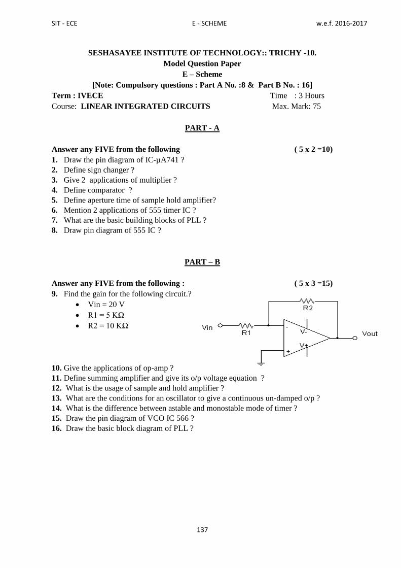
SIT - ECE E - SCHEME w.e.f. 2016-2017
137
SESHASAYEE INSTITUTE OF TECHNOLOGY:: TRICHY -10.
Model Question Paper
E – Scheme
[Note: Compulsory questions : Part A No. :8 & Part B No. : 16]
Term : IVECE Time : 3 Hours
Course: LINEAR INTEGRATED CIRCUITS Max. Mark: 75
PART - A
Answer any FIVE from the following ( 5 x 2 =10)
1. Draw the pin diagram of IC-µA741 ?
2. Define sign changer ?
3. Give 2 applications of multiplier ?
4. Define comparator ?
5. Define aperture time of sample hold amplifier?
6. Mention 2 applications of 555 timer IC ?
7. What are the basic building blocks of PLL ?
8. Draw pin diagram of 555 IC ?
PART – B
Answer any FIVE from the following : ( 5 x 3 =15)
9. Find the gain for the following circuit.?
Vin = 20 V
R1 = 5 KΩ
R2 = 10 KΩ
10. Give the applications of op-amp ?
11. Define summing amplifier and give its o/p voltage equation ?
12. What is the usage of sample and hold amplifier ?
13. What are the conditions for an oscillator to give a continuous un-damped o/p ?
14. What is the difference between astable and monostable mode of timer ?
15. Draw the pin diagram of VCO IC 566 ?
16. Draw the basic block diagram of PLL ?
SIT - ECE E - SCHEME w.e.f. 2016-2017
138
PART – C
Answer all the questions by choosing either (a),(b) or (c) of each question :(5x10 =50)
17) A) Explain& derive the gain equation of Non-Inverting amplifier
( OR )
B) Explain the differential amplifier & derive its o/p voltage equation ?
18) A) Explain about the Integrator
( OR )
B) Explain& derive the o/p voltage equation of instrumentation amplifier?
19) A) Explain and derive the o/p voltage equation of Wein bridge oscillator?
( OR )
B) Explain & derive the o/p voltage equation of log amplifier ?
20) A) Explain the astable mode of timer 555 IC ?
( OR )
B) Explain about the Dual timer 556 ?
21) A)Explain about the basic operation of PLL ?
( OR )
B) Explain about the Frequency translator using PLL 565 ?

SIT - ECE E - SCHEME w.e.f. 2016-2017
139
SESHASAYEE INSTITUTE OF TECHNOLOGY:: TRICHY -10.
Model Question Paper
E – Scheme
[Note: Compulsory questions : Part A No. :8 & Part B No. : 16]
Term : VECE Time : 3 Hours
Course: ADVANCED COMMUNICATION SYSTEM Max. Mark: 75
PART – A
Answer any FIVE from the following ( 5 x 2 =10)
1. What is Crosstalk?
2. What is ASK?
3. State the various Light sources used in fiber Optic Communication.
4. Expand LASER.
5. What is RADAR?
6. Define Satellite Communication.
7. What is a Facsimile Communication System?
8. What is roaming?
PART – B
Answer any FIVE from the following : ( 5 x 3 =15)
9. Mention the advantages and disadvantages of digital communication.
10. Draw the block Diagram of FSK Modulator.
11. Differentiate step index fiber and graded index fiber.
12. State the Losses in Optical Fibers.
13. Draw & explain the block diagram of Transponder.
14. Explain GSM.
15. Give the Expression for RADAR range Equation.
16. State the Features of ISDN.
PART – C
Answer all the questions by choosing either (a),(b) or (c) of each question :(5x10 =50)
17. (A) Explain Digital Communication with a Block diagram.
(OR)
(B) Explain PSK Modulator and Demodulator with neat diagram.
18. (A) Explain LASER diode Operation with neat diagram.
(OR)
(B) Briefly explain the application of optical fibers in Networking Industry and in
Millitary.
19. (A) Explain the Transmit receiver earth station with a block diagram.
(OR)
SIT - ECE E - SCHEME w.e.f. 2016-2017
140
(B) Explain a Microwave link repeater with a block Diagram.
20. (A) Explain the GSM architecture with a diagram.
(OR)
(B) Differentiate TDMA, FDMA and CDMA.
21. (A) Draw & explain the block diagram of pulsed Radar system.
(OR)
(B) Explain Direct recording system used in facsimile receiver.

SIT - ECE E - SCHEME w.e.f. 2016-2017
141
SESHASAYEE INSTITUTE OF TECHNOLOGY:: TRICHY -10.
Model Question Paper
E – Scheme
[Note: Compulsory questions : Part A No. :8 & Part B No. : 16]
Term : VECE Time : 3 Hours
Course: MICROCONTROLLER Max. Mark: 75
PART-A
Answer any FIVE from the following ( 5 x 2 =10)
1. What is the size of internal RAM in 8051 microcontroller?
2.List the flags available in 8051 microcontroller.
3. List the addressing modes in 8051 microcontroller.
4. Write instruction to transfer data 34h to accumulator
5.Mention the various modes of timer in 8051
6.List the various interrupts available in 8051 microcontroller.
7.Define DAC
8. Write the format of TMOD register.
PART-B
Answer any FIVE from the following : ( 5 x 3 =15)
9. Compare microprocessor and microcontroller.
10. Draw the structure of internal RAM
11. Mention the addressing mode of the following instructions.
(i) MOV A, R1
(ii) MOVA,@R0
(iii) ADD A, #55H.
12. Write alternate functions of port 3?
13. Explain the following instructions
(i) MUL AB (ii) RLC A (iii) RR A
14. Write IE register format?
15. Draw the configuration of 9 pin RS 232 standard?
16. Write a program to add the data 65h and 43h
PART-C
Answer all the questions by choosing either (a),(b) or (c) of each question :(5x10 =50)
17. (A) Draw the architecture of 8051 microcontroller and explain
(OR)
(B) (i) Draw the pin details of 8051 microcontroller. (5)
(ii) Explain MOV, MOVX and MOVC instructions (5)

SIT - ECE E - SCHEME w.e.f. 2016-2017
142
18. (A) Explain various addressing modes in 8051 with example
(OR)
(B) Write a program to find the largest number in an array of data
19. (A) (i) Write a simple delay subroutine (5)
(ii) Explain the steps to program the timer 0 in mode 2. (5)
(OR)
(B) Explain the various modes of operation of timer in 8051 microcontroller
20. (A)Write a program to transfer letter „A‟ continuously with a baud rate of
4800 at P1.1 of 8051 microcontroller
(OR)
(B) Explain about the various interrupts available in 8051 microcontroller.
21. (A)Explain how to interface ADC with 8051microcontroller with suitable
diagram.
(OR)
(B) Draw the block diagram microcontroller based temperature indicator.

SIT - ECE E - SCHEME w.e.f. 2016-2017
143
SESHASAYEE INSTITUTE OF TECHNOLOGY:: TRICHY -10.
Model Question Paper
E – Scheme
[Note: Compulsory questions : Part A No. :8 & Part B No. : 16]
Term : VECE Time : 3 Hours
Course: VERY LARGE SCALE INTEGRATION Max. Mark: 75
PART-A
Answer any FIVE from the following ( 5 x 2 =10)
1. What is CMOS ?
2. List few combinational circuit.
3.What is simulation.
4. Write VHDL code for OR gate.
5. Define sequential circuit.
6. Write different modes of shift register.
7. Define state diagram.
8. Write major parts in FPGA.
PART – B
Answer any FIVE from the following : ( 5 x 3 =15)
9. Write short notes on Hazards?
10. Relate variable and function .
11.Wtite different level of obstraction in VHDL
12.Write VHDL code for 4x1 multiplexer.
13. Difference between Latch and flip -flop.
14. Define moore& mealy machine.
15.Write VHDL code for D latch.
16. What is the difference between PLA & PAL ?
PART – C
Answer all the questions by choosing either (a),(b) or (c) of each question :(5x10 =50)
17. (A) With necessary diagrams explain the working of NOT, AND and OR plane
using CMOS.
OR
(B) Implement the function F=∑m (0,2,3,7,12,14,15)
Implement the above function with a 4 to 1 multiplexer.
18. (A) Write VHDL code for decoder and single bit comparator.
OR
(B) Write VHDL code for 4 bit adder.
19. (A) Write and explain excitation table of RS and D flip-flop .

SIT - ECE E - SCHEME w.e.f. 2016-2017
144
OR
(B) Design modulo 5 counter using D flip-flop.
20. (A) Write VHDL code for JK and D flip-flop with reset input.
OR
(B) Write VHDL code for 4 bit up counter.
21. (A) What is PLA? How do you realize the given function with a PLA .
F1 (x,y,z) = ∑m (0,1,3,4)
F2 (x,y,z ) = ∑m (1,2,3,4,5)
OR
(B) With a block diagram, explain the working of CPLD.

SIT - ECE E - SCHEME w.e.f. 2016-2017
145
SESHASAYEE INSTITUTE OF TECHNOLOGY:: TRICHY -10.
Model Question Paper
E – Scheme
[Note: Compulsory questions : Part A No. :8 & Part B No. : 16]
Term : VIECE Time : 3 Hours
Course: BIOMEDICAL INSTRUMENTATION Max. Mark: 75
PART - A
Answer any FIVE from the following ( 5 x 2 =10)
1. State the value of resting and action potential.
2. Define chromatography.
3. Draw ECG wave pattern.
4. Mention any two EEG wave types.
5. What is pacemaker?
6. What are the types of dialysis?
7. What is bio telemetry?
8. What is laser?
PART – B
Answer any FIVE from the following : ( 5 x 3 =15)
9. Define the different types of electrodes.
10. List the techniques used to calculate the heart rate.
11. Mention the standard lead systems used in ECG.
12. What are the different types of audiometer?
13. Compare hemo dialysis and peritoneal dialysis.
14. What are the applications of endoscope?
15. What is micro and macro shock?
16. What are the applications of laser in medicines?
PART – C
Answer all the questions by choosing either (a),(b) or (c) of each question :(5x10 =50)
17. (A) With the diagram explain the indirect method of blood pressure measurement using
Sphygmomanometer.
(OR)
(B) With the diagram explain the principle of chromatography.
18. (A) Draw the block diagram of ECG and explain its working.
(OR)
(B) Explain 10-20 lead system used in EEG.
19. (A) Draw a model of heart lung machine and explain its operation.

SIT - ECE E - SCHEME w.e.f. 2016-2017
146
(OR)
(B) With the diagram explain hemodialysis.
20. (A) Draw the block diagram of bio telemetry transmitter and receiver and explain each
block.
(OR)
(B) Explain the function of ground fault circuit interrupter.
21. (A) With the block diagram explain X-ray machine.
(OR)
(B) Draw the block diagram of CT scanner and explain its operation.
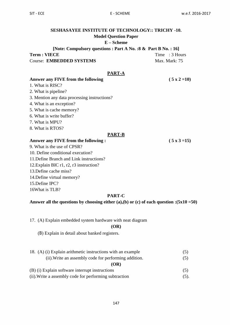
SIT - ECE E - SCHEME w.e.f. 2016-2017
147
SESHASAYEE INSTITUTE OF TECHNOLOGY:: TRICHY -10.
Model Question Paper
E – Scheme
[Note: Compulsory questions : Part A No. :8 & Part B No. : 16]
Term : VIECE Time : 3 Hours
Course: EMBEDDED SYSTEMS Max. Mark: 75
PART-A
Answer any FIVE from the following ( 5 x 2 =10)
1. What is RISC?
2. What is pipeline?
3. Mention any data processing instructions?
4. What is an exception?
5. What is cache memory?
6. What is write buffer?
7. What is MPU?
8. What is RTOS?
PART-B
Answer any FIVE from the following : ( 5 x 3 =15)
9. What is the use of CPSR?
10. Define conditional execution?
11.Define Branch and Link instructions?
12.Explain BIC r1, r2, r3 instruction?
13.Define cache miss?
14.Define virtual memory?
15.Define IPC?
16What is TLB?
PART-C
Answer all the questions by choosing either (a),(b) or (c) of each question :(5x10 =50)
17. (A) Explain embedded system hardware with neat diagram
(OR)
(B) Explain in detail about banked registers.
18. (A) (i) Explain arithmetic instructions with an example (5)
(ii).Write an assembly code for performing addition. (5)
(OR)
(B) (i) Explain software interrupt instructions (5)
(ii).Write a assembly code for performing subtraction (5).

SIT - ECE E - SCHEME w.e.f. 2016-2017
148
19. (A) Explain the cache architecture with neat diagram
(OR)
(B) (i)Explain set associative cache mechanism. (5)
(ii) Write short notes on write buffer. (5)
20. (A) Explain demonstration of an MPU system
(OR)
(B) Explain the working principle of virtual memory.
21. (A) Explain context switching in detail.
(OR)
(B) (i) Explain mutual exclusion semaphore. (5)
(ii) Explain message box in IPC. (5)

SIT - ECE E - SCHEME w.e.f. 2016-2017
149
SESHASAYEE INSTITUTE OF TECHNOLOGY:: TRICHY -10.
Model Question Paper
E – Scheme
[Note: Compulsory questions : Part A No. :8 & Part B No. : 16]
Term : VIECE Time : 3 Hours
Course: INDUSTRIAL ELECTRONICS Max. Mark: 75
PART-A
Answer any FIVE from the following ( 5 x 2 =10)
1. What is the use of OPTO isolator?
2.State the disadvantages of GTO over thyristor.
3.Define commutation and mention its types.
4.Define variable frequency control of chopper.
5.Define SMPS and state its applications.
6.Mention the different types of methods for obtaining sine wave output from an inverter.
7.What is relay and mention its types.
8.Define PLC..
PART – B
Answer any FIVE from the following : ( 5 x 3 =15)
9. State the applications of MOSFET,GTO and IGBT
10. Explain AC gate signal triggering.
11. List any four advantages of flywheel diode?
12. Mention the various types of SMPS.
13. List the methods of obtaining sine wave in inverters?
14.Explain Electromechanical relay.
15.Explain AND logic function used in PLC.
16.Explain the working of ON TIMER.
PART – C
Answer all the questions by choosing either (a),(b) or (c) of each question :(5x10 =50)
17. (A) With a neat circuit diagram ,explain the working of SCR with VI charcteristics.
OR
(B) With a neat circuit diagram ,explain the working of IGBT.
18. (A) With a neat circuit diagram and waveform Explain the resistance capacitance firing
circuit
OR
(B) Explain ramp and pedestal type UJT triggering with circuit diagram and waveform.

SIT - ECE E - SCHEME w.e.f. 2016-2017
150
19. (A) With a neat circuit diagram and waveform Explain AC chopper
OR
(B) Draw and Explain the operation of Class A, C and D commutation.
20. (A) Draw and explain the working of Mc Murray inverter
OR
(B)With a neat sketch Explain ON-line and OFF line UPS.
21. (A) Draw and Explain the Block diagram of PLC
OR
(B) Draw the PLC ladder diagram of star delta starter and Explain its operation
.

SIT - ECE E - SCHEME w.e.f. 2016-2017
151
SESHASAYEE INSTITUTE OF TECHNOLOGY: TRICHY -10.
Model Question Paper
E – Scheme
[Note: Compulsory questions : Part A No. :8 & Part B No. : 16]
Term : VIECE Time : 3 Hours
Course: COMPUTER HARDWARE SERVICING AND NETWORKING
Max. Mark: 75
PART-A
Answer any FIVE from the following ( 5 x 2 =10)
1. Whatistheothernameofmotherboard?
2. Whatisparallelport?
3. What is BIOS?
4. WhatisESD?
5. What is UPS?
6. WhatisVSAT?
7. What is UDP?
8. What is Ethernet?
PART-B
Answer any FIVE from the following : ( 5 x 3 =15)
9. WhatistheuseofultraATA?
10. Define the term modem?
11. Define IPL hardware?
12. WhatisMultiFunctionPrinter?
13. Define half duplex?
14. What is OSI model?
15. Define token bus?
16. Define Telnet?
PART-C
Answer all the questions by choosing either (a),(b) or (c) of each question :(5x10 =50)
17. (A)i)Howwillyouformattheharddisk? (5)
ii) ExplaintheUSB. (5)
(OR)
(B).Discussthe formatandversionofDVD-ROM.
18.(A)i)ExplainindetailaboutSVGA (5).
ii)WritetheworkingprincipleofLCD. (5)
(OR)
(B)Explaintheworkingofwirelesskeyboardwithblockdiagram.
19.(A)HowwillyouupgradeBIOS?
(OR)

SIT - ECE E - SCHEME w.e.f. 2016-2017
152
(B)i)Drawtheblockdiagramoflaptopmotherboardandexplainit. (5)
ii)WritedownthestepsinvolvedinOSinstallation. (5)
20.(A)Withneatdiagramexplainthetypesofnetworks.
(OR)
(B)Discussaboutunguidedtransmissionmediawithneatdiagram.
21.(A)i)WithneatdiagramexplainaboutTELNET. (5)
ii)ExplainindetailaboutSMTP. (5)
(OR)
(B)i) WithneatdiagramexplainaboutVLSMtechnique. (5)
(ii) Write short notes on IPV6 (5)
*******************

SIT - ECE E - SCHEME w.e.f. 2016-2017
153
EQUIVALENT PAPERS

SIT - ECE E - SCHEME w.e.f. 2016-2017
154
III Term
SIT D SCHEME SIT E SCHEME Equivalent/Not
Equivalent
Electronic Devices and Circuits Electronic Devices
and Components
Not Equivalent
Electrical Circuits and Machines Electrical Circuits
and Instrumentation
Not Equivalent
Communication Engineering - I Newly Introduced
C' programming Programming in “C” Equivalent
Electronic Devices and Circuits
lab
Electronic Devices
and Circuits Lab
Equivalent
Electrical Circuits and
Communication Engineering - I
lab
Electrical Circuits
and Instrumentation
Lab
Not Equivalent
C' programming lab Programming in “C”
Lab
Equivalent
Computer
Application Lab for
Electronics
Newly Introduced
IV Term
SIT D SCHEME SIT E SCHEME Equivalent/Not
Equivalent
Electronic Circuits Newly Introduced
Digital Electronics Digital Electronics Not Equivalent
Communication Engineering - II Communication
Engineering
Not Equivalent
Linear Integrated Circuits Linear Integrated
Circuits
Equivalent
Measurements And Instruments
Linear Integrated Circuits & Digital
Electronics Lab
Linear Integrated
Circuits & Digital
Electronics Lab
Equivalent
Communication Engineering - II &
Measurements And Instruments
Lab
Communication
Engineering and
Electronic Circuits
Simulation Lab
Not Equivalent
Communication And Life Skills
Lab
Life and
Employability skill
Lab
Environmental Studies *
V Term

SIT - ECE E - SCHEME w.e.f. 2016-2017
155
SIT D SCHEME SIT E SCHEME Equivalent/Not
Equivalent
Advanced Communication
systems
Advanced Communication
systems
Not Equivalent
Microprocessor And
Microcontroller Microcontroller
Not Equivalent
Elective Theory
(I) VLSI
(II) PLC
Very Large Scale Integration VLSI:Equivalent
Elective I
(I) Digital Communication
(II) Biomedical
Instrumentation
(III) Electronic System
Design
Note:
Biomedical
Instrumentation:
Equivalent to VI
term D scheme
Bio Medical and
Telemedicine
Advanced Communication
systems lab
Advanced Communication
systems Lab
Equivalent
Micro Controller lab Microcontroller Lab Equivalent
Elective Practical
(I) VLSI Lab
(II) PLC Lab
Very Large Scale Integration
Lab
VLSI lab
Equivalent
Electronic Circuits Design
and Simulation Lab
Disaster Management*
VI Term
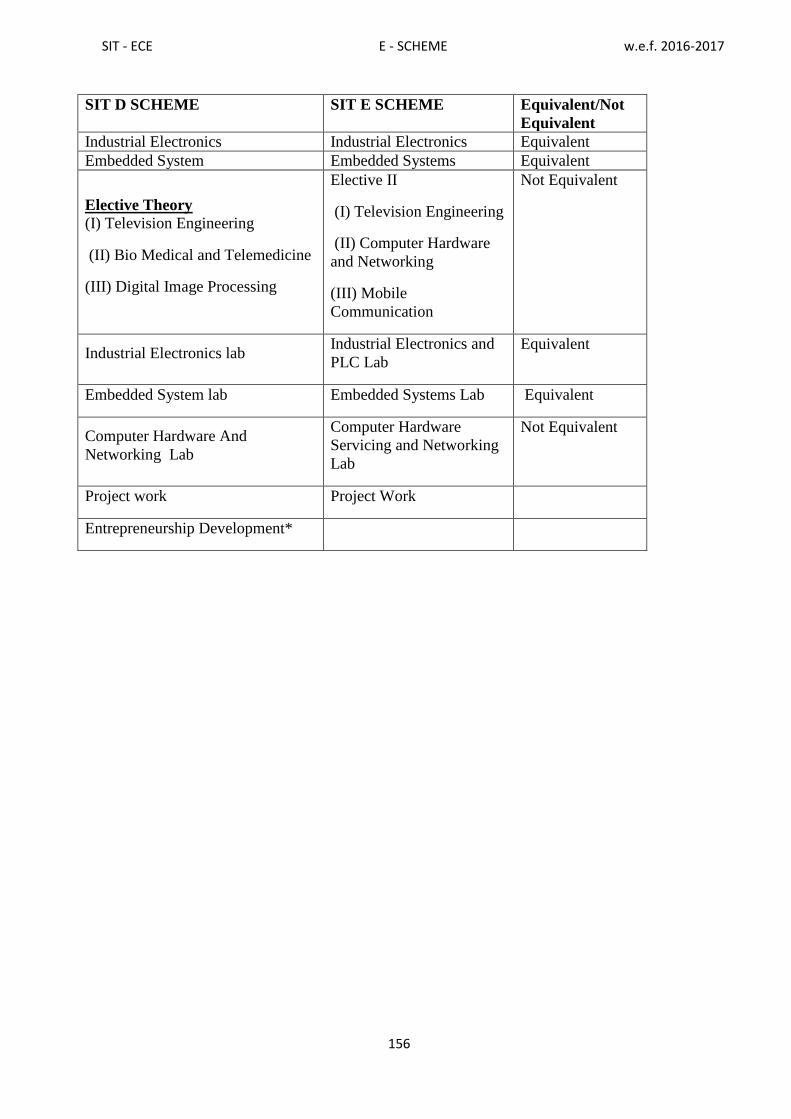
SIT - ECE E - SCHEME w.e.f. 2016-2017
156
SIT D SCHEME SIT E SCHEME Equivalent/Not
Equivalent
Industrial Electronics Industrial Electronics Equivalent
Embedded System Embedded Systems Equivalent
Elective Theory
(I) Television Engineering
(II) Bio Medical and Telemedicine
(III) Digital Image Processing
Elective II
(I) Television Engineering
(II) Computer Hardware
and Networking
(III) Mobile
Communication
Not Equivalent
Industrial Electronics lab Industrial Electronics and
PLC Lab
Equivalent
Embedded System lab Embedded Systems Lab Equivalent
Computer Hardware And
Networking Lab
Computer Hardware
Servicing and Networking
Lab
Not Equivalent
Project work Project Work
Entrepreneurship Development*