direct drive motor intelligent drive
TRANSCRIPT

TI 71M01D03-01EN Yokogawa Electric Corporation 11th Edition:2012.12.01
Technical Information
Direct Drive Motor <DYNASERV> Intelligent Drive <DrvGIII> Technical Information
TI 71M01D03-01EN

Blank Page
i
TI 71M01D03-01EN 11th Edition: 2012.12.01
Introduction Overview of This Manual
This manual provides information about DYNASERV, a direct drive servo motor. Make sure to refer to this manual when you use the motor.
Trademark
• Windows and Windows NT are registered trademarks of Microsoft Corporation in the
United States and/or other countries. • Adobe and Acrobat are trademarks of Adobe Systems Incorporated. • Pentium is a registered trademark of Intel Corporation in the United States. • Other company and product names mentioned herein may be the trademarks or
registered trademarks of their respective owners. Copyright
The copyright of this manual belongs to Yokogawa Electric Corporation. No part of this document may be reproduced, or transferred, sold or distributed to the third party.
Strategic Goods Advisory
It is required to obtain approval from the Japanese government to export goods regulated by the Foreign Exchange and Foreign Trade Control Law from Japan.
ii
TI 71M01D03-01EN 11th Edition: 2012.12.01
Conventions Symbols used in this manual
Throughout this manual, the following symbol marks are used to distinguish explained information.
: Describes cautions for avoiding danger in potentially hazardous situations that may put operators' lives and bodies in danger such as electric shock accident.
: Describes points to be noted in situations that may cause damages to software and/or hardware or system troubles.
: Describes important points when understanding operations and
functions. : Describes supplementary information about descriptions. : Describes items and pages that should be referenced.
! DANGER
WARNING
CAUTION
TIP
SEE ALSO
iii
TI 71M01D03-01EN 11th Edition: 2012.12.01
Precautions Precautions Regarding this Manual
• Please make sure this manual is made available to all end users. • Do not operate the product before reading this manual and thoroughly understanding
its contents. • This manual was created to provide detailed explanations of the functions offered by
the product. It is not guaranteed that it will suit any particular purpose a customer might have.
• The reproduction or copying of any portion of this manual is strictly prohibited without prior permission from Yokogawa Electric.
• The information provided in this manual is subject to change without notice. • If you have any questions or find any errors and/or omissions in the information
provided in this manual, please contact our Sales Department or the dealer from whom the product was purchased.
Precautions Regarding Protection, Safety and Product Modification
• To ensure your protection and that of the product, as well as the systems that use the product, please observe all safety instructions and other precautions listed in this manual.
• If you operate the product in a manner contrary to the instructions provided in this manual, the safety protection may be lost. In such an event, we make no warranties for the quality, performance, functions and safety of the product.
• If you install protection/safety circuits for the product or systems that use this product, make sure to install them on the product separately and externally. Do not install them inside the product, nor should any internal parts of the product be modified in order to do so.
• Be sure to replace any parts and consumables of the product with parts specified by us.
• This product is neither designed nor manufactured to be used under conditions that may directly affect the safety of humans including in nuclear or radiation-related devices, railway facilities, aircraft instruments, marine instruments, air-navigation facilities or medical devices. If it is necessary to apply the product in systems that directly affect the safety of humans, it is the user's own responsibility to construct a system for securing the safety of humans with devices and equipment other than the applicable product.
• Modification of the product is strictly prohibited. Product Disclaimer
• We make no warranty for the product except as prescribed by the guarantees. • We assume no responsibility for damages any user or third party may incur through
use of the product, nor for any direct or indirect damages that the user or a third party may incur due to product defects that cannot be predicted by us, etc.

iv
TI 71M01D03-01EN 11th Edition: 2012.12.01
Software
• We make no warranties for the software except as prescribed by the guarantees. • Copying and use of the software for any purpose other than as intended by us, such
as for use as a backup, is strictly prohibited. • Keep the original storage media of this software in a safe place. If you do not have the
original media, we may decline to offer our prescribed quality warranty and maintenance services.
• Reverse engineering of the software, including reverse compilation and reverse assembly, is strictly prohibited.
• The transfer, exchange or subleasing of any part of the software for unwarranted use by a third party is prohibited without prior permission from Yokogawa Electric.
v
TI 71M01D03-01EN 11th Edition: 2012.12.01
General Precautions Regarding DYNASERV
• Never install the DYNASERV motor in reverse, i.e. fixing the rotor of the motor and making the stator rotate.
• When removing the drive-side panel to replace consumables, etc., be sure to turn the power OFF before doing so. It is dangerous to touch the high-voltage parts inside the unit.
• The motor rotates at a high velocity and torque. Take the rotation radius into consideration during operations with load attached, and be sure to take precautions to avoid the risk of bodily injury or equipment damage.
• Be sure to ground the ground terminal to the earth. • When mounting a load on the motor rotor, be sure to leave a clearance between the
load and the upper surface of the motor of 1mm or more in order to maintain the intended precision.
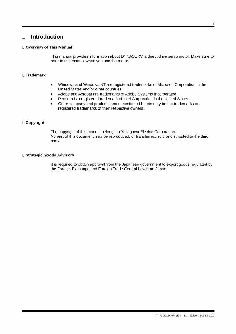
• Never press an object into the hollow hole or apply force to it. When you lead an object through the hollow hole, be sure to secure a clearance of 1 mm or more on both sides. If force is applied to the hollow hole in the DM motor, the internal encoder may be damaged. The DR motor has a hollow hole in its casting, so take the dimensional allowance into consideration and use it with sufficient margins for both sizes and shapes.
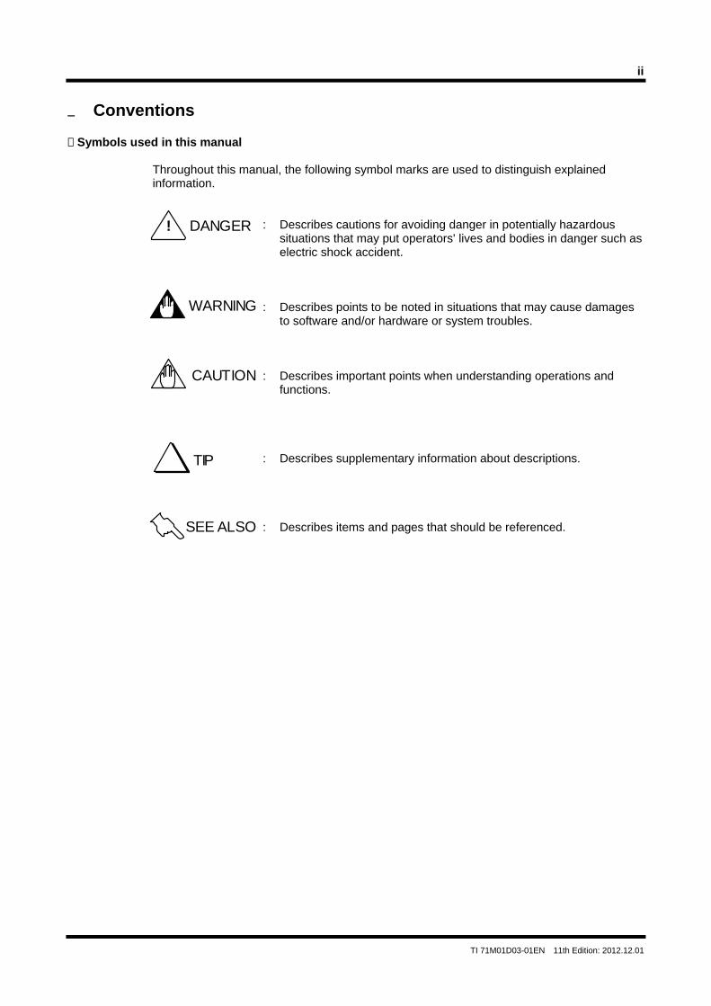
• Do not subject the motor to strong force, impact or magnetic field. Please be aware that the DR motor is equipped with a built-in magnetic resolver.
• Be sure the mounting screws of a load never reach or exceed the effective screw depth of the motor unit. Depending on the model used, the functions may be impaired and failure may occur if screws reach or exceed the effective screw depth.
• If you use the screw holes located above and below the box of the DrvGIII drive, be certain the tips of the screws penetrate no more than 8mm for the 500W and 2kW classes, or 6mm for the 4kW class, below the drive's surface. If this precaution is not observed, it may cause an electric shock, short circuit and/or damage to the motor.
Bottom cover
Magnetic resolver
Stator
Rotor
Motor rotor
Attached part
Motor's hollow hole
1 m
m o
r m
ore
1 mm or more
Object to be led through hollow hole
vi
TI 71M01D03-01EN 11th Edition: 2012.12.01
• If you intend to use the motor in applications where the move is sliding/rotating at a small angle (50°or less), it is necessary to perform a reciprocating move (rotate the motor 180°from the operational range of motion) of 90°or more approximately 10 times for every 10,000 cycles of the small-angle move in order to prevent the bearing lubrication from becoming insufficient.
• The motor's surface is magnetized. Keep objects that are affected by magnetism away from the motor.
• The motor and drive structures are not resistant to dust, splash or water (oil). Therefore, choose the installation environment carefully.
• The drive should be installed on an appropriate metal cabinet, observing the safety measures prescribed by the Low Voltage Directive and EMC Directives.
• Interchangeability between motors and drives is only possible if the drive and motor are compatible (not every motor can be connected to every drive). To determine compatibility, the DYNASERV motor's five digit model and suffix code must match the drive's five digit model and suffix code. For example, using to represent the model and suffix code values, the motor's five digit model and suffix code (DM- or DR-) must match the drive's model and suffix code (UDG3- or URG3), respectively. In addition, the current of the drive must also match the motor requirements.
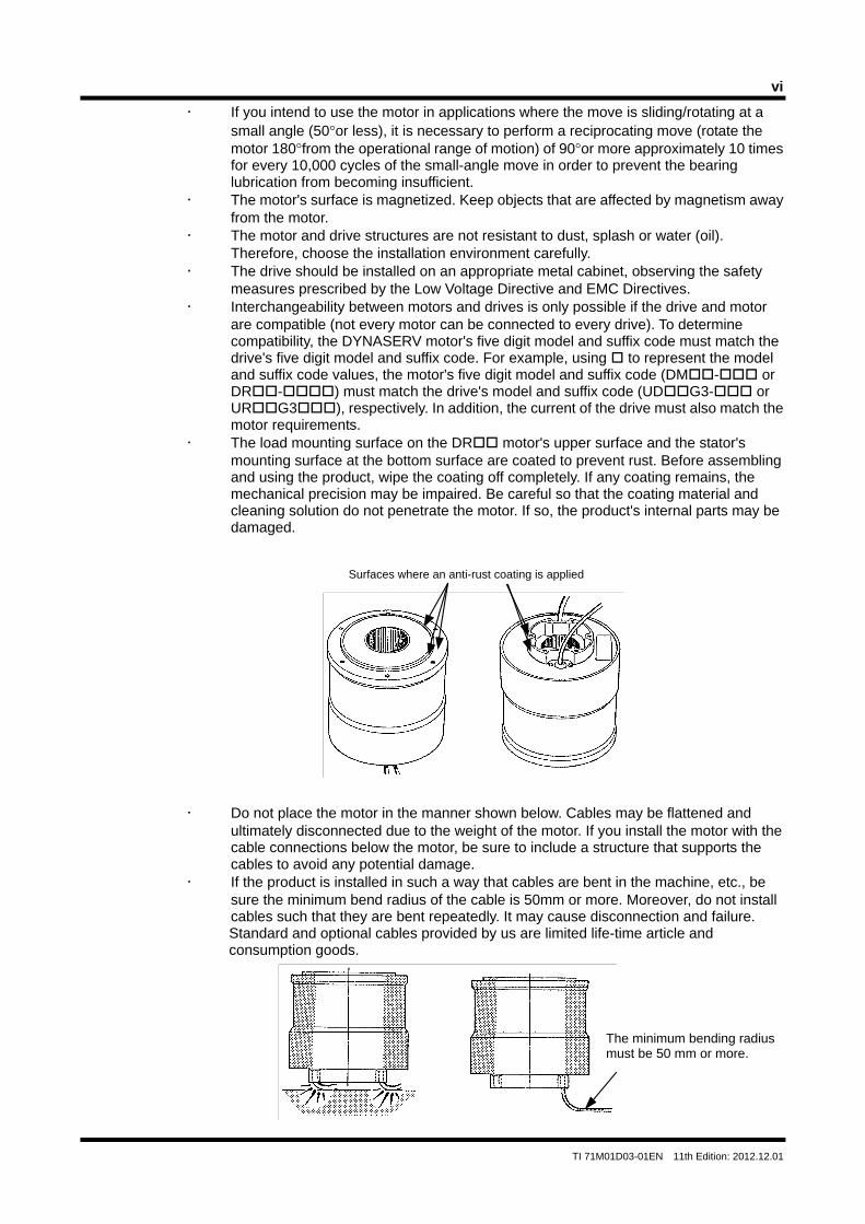
• The load mounting surface on the DR motor's upper surface and the stator's mounting surface at the bottom surface are coated to prevent rust. Before assembling and using the product, wipe the coating off completely. If any coating remains, the mechanical precision may be impaired. Be careful so that the coating material and cleaning solution do not penetrate the motor. If so, the product's internal parts may be damaged.
• Do not place the motor in the manner shown below. Cables may be flattened and ultimately disconnected due to the weight of the motor. If you install the motor with the cable connections below the motor, be sure to include a structure that supports the cables to avoid any potential damage.
• If the product is installed in such a way that cables are bent in the machine, etc., be sure the minimum bend radius of the cable is 50mm or more. Moreover, do not install cables such that they are bent repeatedly. It may cause disconnection and failure. Standard and optional cables provided by us are limited life-time article and consumption goods.
Surfaces where an anti-rust coating is applied
The minimum bending radius must be 50 mm or more.
vii
TI 71M01D03-01EN 11th Edition: 2012.12.01
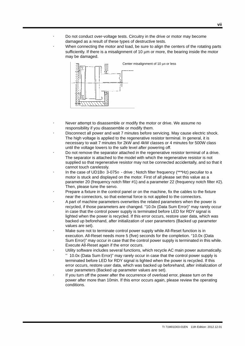
Center misalignment of 10 μm or less
• Do not conduct over-voltage tests. Circuitry in the drive or motor may become
damaged as a result of these types of destructive tests. • When connecting the motor and load, be sure to align the centers of the rotating parts
sufficiently. If there is a misalignment of 10 μm or more, the bearing inside the motor may be damaged.
• Never attempt to disassemble or modify the motor or drive. We assume no
responsibility if you disassemble or modify them. • Disconnect all power and wait 7 minutes before servicing. May cause electric shock.
The high voltage is applied to the regenerative resistor terminal. In general, it is necessary to wait 7 minutes for 2kW and 4kW classes or 4 minutes for 500W class until the voltage lowers to the safe level after powering off.
• Do not remove the separator attached in the regenerative resistor terminal of a drive. The separator is attached to the model with which the regenerative resistor is not supplied so that regenerative resistor may not be connected accidentally, and so that it cannot touch carelessly.
• In the case of UD1B3-075- drive ; Notch filter frequency (***Hz) peculiar to a motor is stuck and displayed on the motor. First of all please set this value as a parameter 20 (frequency notch filter #1) and a parameter 22 (frequency notch filter #2). Then, please tune the servo.
• Prepare a fixture in the control panel or on the machine, fix the cables to the fixture near the connectors, so that external force is not applied to the connectors.
• A part of machine parameters overwrites the related parameters when the power is recycled, if those parameters are changed. “10.0x (Data Sum Error)” may rarely occur in case that the control power supply is terminated before LED for RDY signal is lighted when the power is recycled. If this error occurs, restore user data, which was backed up beforehand, after initialization of user parameters (Backed up parameter values are set).
• Make sure not to terminate control power supply while All-Reset function is in execution. All-Reset needs more 5 (five) seconds for the completion. “10.0x (Data Sum Error)” may occur in case that the control power supply is terminated in this while. Execute All-Reset again if the error occurs.
• Utility software includes several functions, which recycle AC main power automatically. “10.0x (Data Sum Error)” may rarely occur in case that the control power supply is terminated before LED for RDY signal is lighted when the power is recycled. If this error occurs, restore user data, which was backed up beforehand, after initialization of user parameters (Backed up parameter values are set).
• If you turn off the power after the occurrence of overload error, please turn on the power after more than 10min. If this error occurs again, please review the operating conditions.

Blank Page
TOC-1
TI 71M01D03-01EN 11th Edition: 2012.12.01
Table of Contents
Introduction ............................................................................................................................................... i Conventions ............................................................................................................................................. ii Precautions ............................................................................................................................................. iii 1. Overview of the Product ....................................................................................................................... 1-1
1.1 DM/DR Series Motor .................................................................................................................... 1-1 1.2 DrvGIII Drive ................................................................................................................................. 1-1 1.2 Checking the Product ................................................................................................................... 1-2
2. Specifications ....................................................................................................................................... 2-1
2.1 Standard Specifications ................................................................................................................ 2-1 2.2 Torque/Velocity Characteristics .................................................................................................... 2-6 2.3 Model and Suffix Codes ............................................................................................................... 2-8 2.4 Option Cables ............................................................................................................................. 2-16
2.4.1 Option Cable Model and Suffix Code ............................................................................... 2-16 2.4.2 Recommended Cables ..................................................................................................... 2-19 2.4.3 Cable Specifications ......................................................................................................... 2-21
2.5 Outline Drawings ........................................................................................................................ 2-24 2.5.1 Motor ................................................................................................................................ 2-24 2.5.2 Drive ................................................................................................................................. 2-29 2.5.3 Regenerative Resistor ...................................................................................................... 2-30 2.5.4 Connector ......................................................................................................................... 2-30 2.5.5 Terminals .......................................................................................................................... 2-31 2.5.6 Motor Filter ....................................................................................................................... 2-31
2.6 Optional Mechanical Brake ......................................................................................................... 2-32 2.6.1 General Specification ....................................................................................................... 2-32 2.6.2 Structure ........................................................................................................................... 2-32 2.6.3 Operation .......................................................................................................................... 2-32 2.6.4 Formulae for Calculation of Stop Angle ........................................................................... 2-33 2.6.5 Applied Voltage and Temperature Increase ..................................................................... 2-33 2.6.6 Power Supply Specifications and Wiring .......................................................................... 2-34 2.6.7 Diagrams of External Appearance ................................................................................... 2-34
2.7 Precautions at Installation, Moving and Storage ........................................................................ 2-35 2.7.1 Installation of the Motor .................................................................................................... 2-35 2.7.2 Installation of the Drive ..................................................................................................... 2-37
2.8 Stop Function in Error State ....................................................................................................... 2-40 2.8.1 Servo-Deceleration ........................................................................................................... 2-40 2.8.2 Dynamic Brake (with selection -1B or -1L) ....................................................................... 2-42 2.8.3 Example ............................................................................................................................ 2-43
2.9 Operating Restrictions ................................................................................................................ 2-45 2.9.1 Restrictions due to Motor Characteristics (DR5B and DR5C) ......................................... 2-45 2.9.2 Restrictions due to Drive Characteristics (DR5B) ............................................................ 2-46 2.9.3 Restrictions on the Number of EEPROM Registrations ................................................... 2-47
2.10 Conformed Standards ................................................................................................................ 2-48
TOC-2
TI 71M01D03-01EN 11th Edition: 2012.12.01
3. System Configuration ........................................................................................................................... 3-1 4. Name and Function of Each Part ......................................................................................................... 4-1
4.1 Motor Unit ..................................................................................................................................... 4-1 4.1.1 DM Type ...................................................................................................................... 4-1 4.1.2. DR Type ...................................................................................................................... 4-1
4.2 Drive Unit ...................................................................................................................................... 4-2 4.2.1 500W Class ........................................................................................................................ 4-2 4.2.2 2kW Class .......................................................................................................................... 4-3 4.2.3 Explanation of the Front Panel ........................................................................................... 4-4
5. Wiring ................................................................................................................................................... 5-1
5.1 Overall Connection ....................................................................................................................... 5-1 5.1.1 Connection Diagram ........................................................................................................... 5-1 5.1.2 Circuit Protector .................................................................................................................. 5-2 5.1.3 List of Recommended Parts ............................................................................................... 5-2 5.1.4 List of Cable Specifications ................................................................................................ 5-3
5.2 Main Power Supply/Control Power Supply Terminal <TB1> ........................................................ 5-4 5.3 Motor Terminal/Ground <TB2> ..................................................................................................... 5-5 5.4 Regenerative Resistor Terminal <TB3> ....................................................................................... 5-6 5.5 Sensor Terminal <TB4> ............................................................................................................... 5-7 5.6 Serial Interface Connector <CN1> ............................................................................................... 5-9 5.7 Encoder/Resolver Connector <CN2> ......................................................................................... 5-11 5.8 Analog Monitor Connector <CN3> ............................................................................................. 5-14 5.9 Controller Interface Connector <CN4> ....................................................................................... 5-15 5.10 Noise Prevention and Installation Conditions ............................................................................. 5-22
5.10.1 Line Filter ........................................................................................................................ 5-23 5.10.2 Ferrite Core 1 .................................................................................................................. 5-24 5.10.3 Ferrite Core 2 .................................................................................................................. 5-24 5.10.4 Motor Filter ...................................................................................................................... 5-24 5.10.5 Shielding of Cables ......................................................................................................... 5-24
5.11 Drive Input Current ................................................................................................................... 5-25 5.11.1 How to Obtain Input Current ........................................................................................... 5-25 5.11.2 How to Obtain Input Current When Operating Multiple Drives ....................................... 5-27
5.12 Drive Inrush Current ................................................................................................................. 5-28 5.12.1 Inrush Current Waveforms (representative examples)................................................... 5-28 5.12.2 Selecting Circuit Breaker ................................................................................................ 5-28 5.12.3 Selecting Fuse ................................................................................................................ 5-29
6. Operation ............................................................................................................................................. 6-1
6.1 Common Basic Functions ............................................................................................................. 6-1 6.1.1 I/O Signals .......................................................................................................................... 6-1 6.1.2 #parameters/#monitors .................................................................................................... 6-14 6.1.3 Operation Privilege ........................................................................................................... 6-21 6.1.4 Process Settings in Error State ........................................................................................ 6-23 6.1.5 Methods of Issuing Servo-ON Commands ....................................................................... 6-27 6.1.6 Signal Timing when Turning the Power ON ..................................................................... 6-28 6.1.7 Coordinate Systems ......................................................................................................... 6-30
TOC-3
TI 71M01D03-01EN 11th Edition: 2012.12.01
6.1.8 Basic Control Modes ........................................................................................................ 6-34 6.1.9 Velocity Profile .................................................................................................................. 6-36
6.2 Initial Operation Test .................................................................................................................. 6-42 6.2.1 Initial Operation Test Using the Utility Software ............................................................... 6-42
6.3 Jog Move .................................................................................................................................... 6-50 6.4 Table Data Operation ................................................................................................................. 6-54
6.4.1 Table Data Operation ....................................................................................................... 6-54 6.4.2 Setting Operation Register ............................................................................................... 6-62 6.4.3 Auto-tuning Operation ...................................................................................................... 6-67 6.4.4 Test Operation .................................................................................................................. 6-71 6.4.5 Homing ............................................................................................................................. 6-74 6.4.6 ABS (Absolute) Positioning Move .................................................................................... 6-86 6.4.7 INC (Incremental) Positioning Move ................................................................................. 6-89 6.4.8 Dwell ................................................................................................................................. 6-92 6.4.9 Parameter Change ........................................................................................................... 6-93 6.4.10 Conditional Branch ........................................................................................................... 6-97 6.4.11 Command ......................................................................................................................... 6-99 6.4.12 Startup Operation ........................................................................................................... 6-102
6.5 Control Using the PLC .............................................................................................................. 6-103 6.5.1 Position Control Mode .................................................................................................... 6-103 6.5.2 Velocity Control Mode .................................................................................................... 6-109 6.5.3 Torque/thrust Control Mode ........................................................................................... 6-112
6.6 Position Settling Signal ............................................................................................................. 6-115 6.7 Signal Monitor Function ............................................................................................................ 6-118 6.8 Area Signal ............................................................................................................................... 6-121 6.9 Torque/thrust Control Function ................................................................................................. 6-122 6.10 Torque/thrust Feedforward Function ........................................................................................ 6-123 6.11 Homing Using the PLC ............................................................................................................. 6-124
7. Tuning .................................................................................................................................................. 7-1
7.1 How to Tune the Servo ................................................................................................................. 7-1 7.2 Resonance Prevention ................................................................................................................. 7-3
7.2.1 Prevention of Mechanical Resonance ................................................................................ 7-3 7.2.2 Filters .................................................................................................................................. 7-4 7.2.3 If the Motor Oscillates during Auto-tuning ........................................................................ 7-10
8. Utility Software ..................................................................................................................................... 8-1
8.1 Introduction ................................................................................................................................... 8-1 8.1.1 Operating Conditions .......................................................................................................... 8-1 8.1.2 Communication Cable ........................................................................................................ 8-2 8.1.3 Installing and Uninstalling ................................................................................................... 8-3
8.2 Overview ....................................................................................................................................... 8-4 8.2.1 Function Groups ................................................................................................................. 8-4 8.2.2 Function List ....................................................................................................................... 8-5
8.3 Required Settings Prior to Connecting ......................................................................................... 8-7 8.3.1 Connecting and Reconnecting ........................................................................................... 8-7 8.3.2 Communication Settings .................................................................................................... 8-7 8.3.3 Other Settings ..................................................................................................................... 8-8
8.4 Details of the Operation Group Function ...................................................................................... 8-9
TOC-4
TI 71M01D03-01EN 11th Edition: 2012.12.01
8.4.1 Operation ............................................................................................................................ 8-9 8.4.2 Terminal ............................................................................................................................ 8-10
8.5 Details of the Display Group Function ........................................................................................ 8-14 8.5.1 Oscilloscope ..................................................................................................................... 8-14 8.5.2 Displaying #parameter/ #monitor ..................................................................................... 8-26 8.5.3 I/O monitor ........................................................................................................................ 8-27 8.5.4 Axis Signal Monitor ........................................................................................................... 8-28 8.5.5 Error Monitor ..................................................................................................................... 8-29
8.6 Details of the Data Management Group Function ...................................................................... 8-30 8.6.1 #parameters ..................................................................................................................... 8-30 8.6.2 Table Data Function ......................................................................................................... 8-34 8.6.3 I/O ..................................................................................................................................... 8-35
8.7 Details of the Maintenance Group Function ............................................................................... 8-37 8.7.1 #parameter Maintenance ................................................................................................. 8-37 8.7.2 Table Data Maintenance .................................................................................................. 8-38 8.7.3 I/O Maintenance ............................................................................................................... 8-39 8.7.4 Backup .............................................................................................................................. 8-40 8.7.5 Version Information .......................................................................................................... 8-41
8.8 FAQ Pertaining to the Utility Software ........................................................................................ 8-42 9. Maintenance and Inspection ................................................................................................................ 9-1
9.1 Daily Inspection ............................................................................................................................ 9-1 9.2 Backup and Restore Operations of User Data ............................................................................. 9-2 9.3 Initialization of User Data (Reset All) ............................................................................................ 9-2
Appendix 1 Parameter Description .............................................................................................. Appendix 1-1 Appendix 2 Monitor Description ................................................................................................... Appendix 2-1 Appendix 3 Details of Main Error Codes ...................................................................................... Appendix 3-1 Appendix 4 Glossary .................................................................................................................... Appendix 4-1 Appendix 5 Descriptions of Operation Table and Sample Programs ........................................... Appendix 5-1 • Revision Record
1-1
TI 71M01D03-01EN 11th Edition: 2012.12.01
1. Overview of the Product 1.1 DM/DR Series Motor
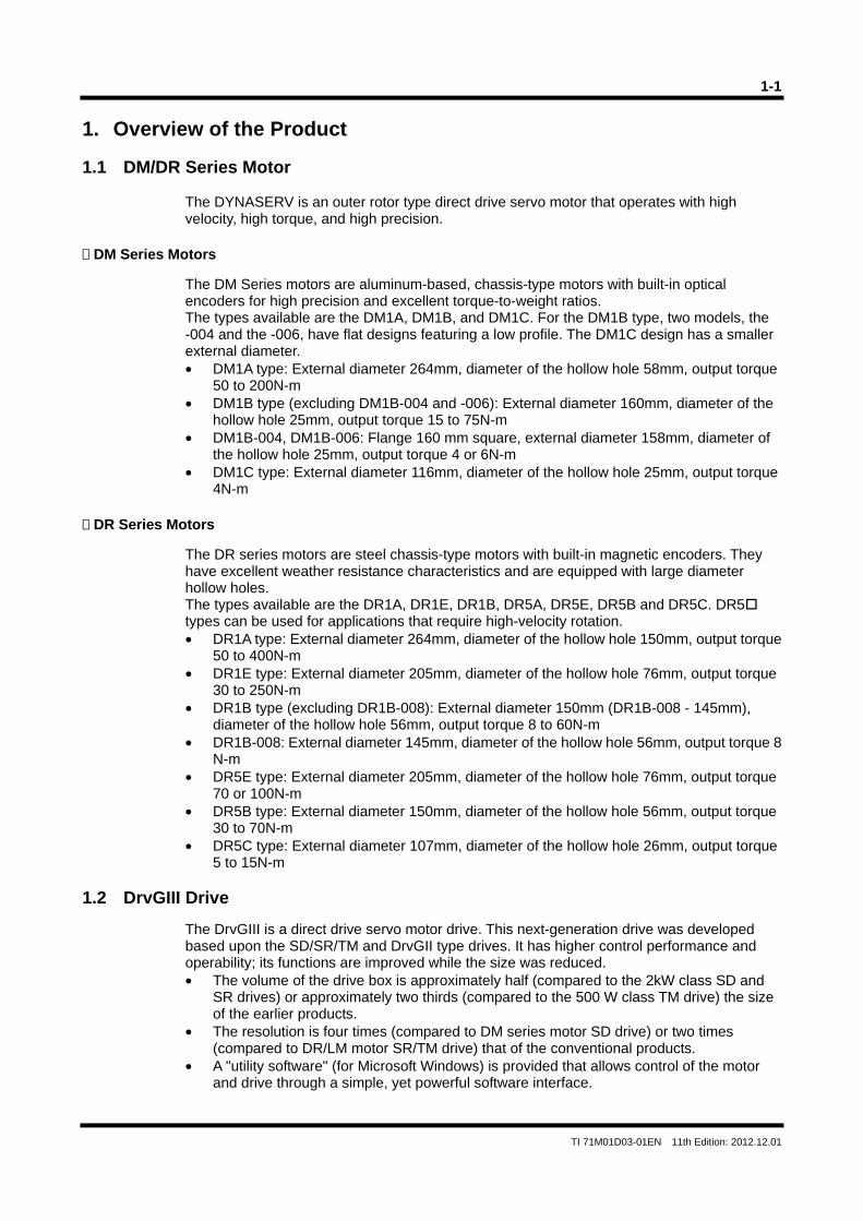
The DYNASERV is an outer rotor type direct drive servo motor that operates with high velocity, high torque, and high precision.
DM Series Motors
The DM Series motors are aluminum-based, chassis-type motors with built-in optical encoders for high precision and excellent torque-to-weight ratios. The types available are the DM1A, DM1B, and DM1C. For the DM1B type, two models, the -004 and the -006, have flat designs featuring a low profile. The DM1C design has a smaller external diameter. • DM1A type: External diameter 264mm, diameter of the hollow hole 58mm, output torque
50 to 200N-m • DM1B type (excluding DM1B-004 and -006): External diameter 160mm, diameter of the
hollow hole 25mm, output torque 15 to 75N-m • DM1B-004, DM1B-006: Flange 160 mm square, external diameter 158mm, diameter of
the hollow hole 25mm, output torque 4 or 6N-m • DM1C type: External diameter 116mm, diameter of the hollow hole 25mm, output torque
4N-m DR Series Motors
The DR series motors are steel chassis-type motors with built-in magnetic encoders. They have excellent weather resistance characteristics and are equipped with large diameter hollow holes. The types available are the DR1A, DR1E, DR1B, DR5A, DR5E, DR5B and DR5C. DR5 types can be used for applications that require high-velocity rotation. • DR1A type: External diameter 264mm, diameter of the hollow hole 150mm, output torque
50 to 400N-m • DR1E type: External diameter 205mm, diameter of the hollow hole 76mm, output torque
30 to 250N-m • DR1B type (excluding DR1B-008): External diameter 150mm (DR1B-008 - 145mm),
diameter of the hollow hole 56mm, output torque 8 to 60N-m • DR1B-008: External diameter 145mm, diameter of the hollow hole 56mm, output torque 8
N-m • DR5E type: External diameter 205mm, diameter of the hollow hole 76mm, output torque
70 or 100N-m • DR5B type: External diameter 150mm, diameter of the hollow hole 56mm, output torque
30 to 70N-m • DR5C type: External diameter 107mm, diameter of the hollow hole 26mm, output torque
5 to 15N-m 1.2 DrvGIII Drive
The DrvGIII is a direct drive servo motor drive. This next-generation drive was developed based upon the SD/SR/TM and DrvGII type drives. It has higher control performance and operability; its functions are improved while the size was reduced. • The volume of the drive box is approximately half (compared to the 2kW class SD and
SR drives) or approximately two thirds (compared to the 500 W class TM drive) the size of the earlier products.
• The resolution is four times (compared to DM series motor SD drive) or two times (compared to DR/LM motor SR/TM drive) that of the conventional products.
• A "utility software" (for Microsoft Windows) is provided that allows control of the motor and drive through a simple, yet powerful software interface.
1-2
TI 71M01D03-01EN 11th Edition: 2012.12.01
1.3 Checking the Product
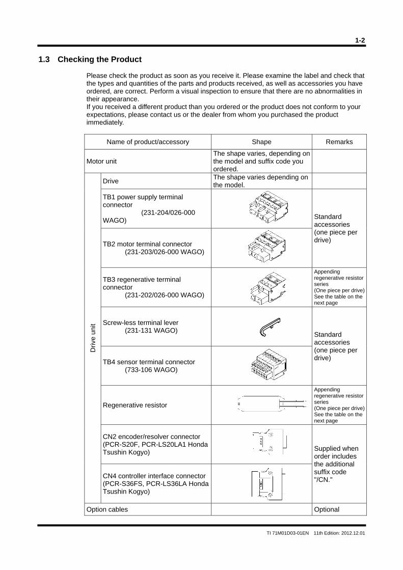
Please check the product as soon as you receive it. Please examine the label and check that the types and quantities of the parts and products received, as well as accessories you have ordered, are correct. Perform a visual inspection to ensure that there are no abnormalities in their appearance. If you received a different product than you ordered or the product does not conform to your expectations, please contact us or the dealer from whom you purchased the product immediately.
Name of product/accessory Shape Remarks
Motor unit The shape varies, depending on the model and suffix code you ordered.
Driv
e un
it
Drive The shape varies depending on the model.
TB1 power supply terminal connector (231-204/026-000 WAGO)
Standard accessories (one piece per drive)
TB2 motor terminal connector (231-203/026-000 WAGO)
TB3 regenerative terminal connector (231-202/026-000 WAGO)
Appending regenerative resistor series (One piece per drive)See the table on the next page
Screw-less terminal lever (231-131 WAGO)
Standard accessories (one piece per drive)
TB4 sensor terminal connector (733-106 WAGO)
Regenerative resistor
Appending regenerative resistor series (One piece per drive)See the table on the next page
CN2 encoder/resolver connector (PCR-S20F, PCR-LS20LA1 Honda Tsushin Kogyo)
Supplied when order includes the additional suffix code "/CN." CN4 controller interface connector
(PCR-S36FS, PCR-LS36LA Honda Tsushin Kogyo)
Option cables Optional
1-3
TI 71M01D03-01EN 11th Edition: 2012.12.01
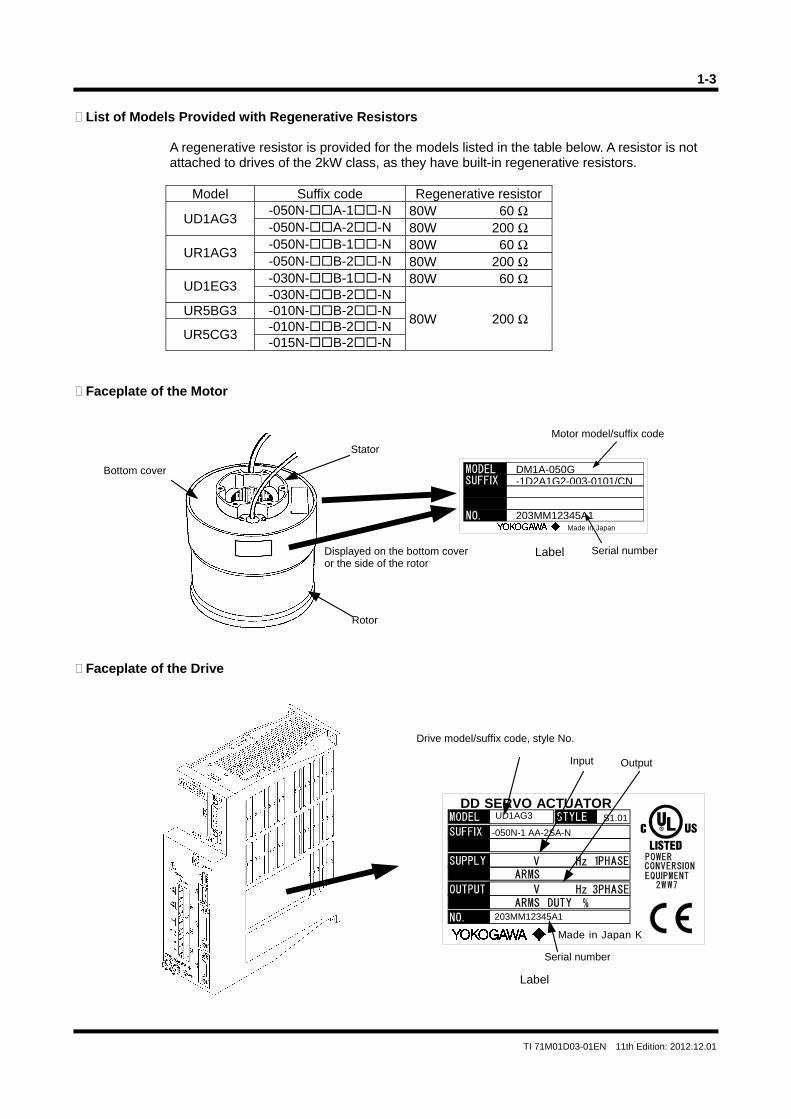
List of Models Provided with Regenerative Resistors
A regenerative resistor is provided for the models listed in the table below. A resistor is not attached to drives of the 2kW class, as they have built-in regenerative resistors.
Model Suffix code Regenerative resistor
UD1AG3 -050N-A-1-N 80W 60 Ω -050N-A-2-N 80W 200 Ω
UR1AG3 -050N-B-1-N 80W 60 Ω -050N-B-2-N 80W 200 Ω
UD1EG3 -030N-B-1-N 80W 60 Ω -030N-B-2-N
80W 200 Ω UR5BG3 -010N-B-2-N
UR5CG3 -010N-B-2-N -015N-B-2-N
Faceplate of the Motor
Faceplate of the Drive
Made in Japan
Bottom cover-1D2A1G2-003-0101/CNDM1A-050G
Label
Motor model/suffix code
Serial number
Stator
Rotor
Displayed on the bottom cover or the side of the rotor
203MM12345A1
Made in Japan K
DD SERVO ACTUATOR
C
Label
Drive model/suffix code, style No.
Input Output
Serial number
UD1AG3
-050N-1 AA-2SA- N S1.01
203MM12345A1

Blank Page
TI 71M01D03-01EN 11th Edition : 2012.12.01
2-1
DM1A
DM1A-200 DM1A-150
200 150
0.5/1.0
DM1A-100 DM1A-050
100 50
1.0/1.0
Item
Compression
Tension
Mot
or
Mo
tor
and
driv
e
Unit
N・m
arc-sec
rps
kg・m2
mm/N
N・m
N
mm
kg
rad/N・m
±1
4×10⁴
2×10⁴
400
2×10⁻⁶
3×10⁻⁶
4×10⁻⁷
96×10-3
14.5
113
119×10-3
19
138
142×10-3
24
163
167×10-3
29
188
Repeatability accuracy
Maximum torque
Rated velocity (100/200V)
Rotor inertia
Maximum overhung load
Moment displacement stiffness
Weight
Standard profile
Axial load
Axial stiffness
p/rev 4,096,000Encoder resolution
Absolute accuracy
kVA
±15
mm 163188213238With mechanical brake
Length L (See the outline drawings.)
Maximum power consumption(100/200V) 1.5/3.0 1.5/3.0 1.35/2.7 1.2/2.4
Rated torque * N・m 67 50 33 17
1.2/1.2rpsMaximum velocity (100/200V)
kVARated power consumption(100/200V) * 1.32/1.9 1.12/1.5 1.12/1.12 0.71/0.71
Rotation Positioning
Number of origin pulses 100p/rev
Rotation positioning
Item
Repeatability accuracy arc-sec
p/rev
rps
kg・m2
mm/N
N・m
N
mm
kg
rad/N・m
Maximum torque
Rated velocity (100/200V)
Rotor inertia
Maximum overhung load
Moment displacement stiffness
Axial load
Axial stiffness
N・m
Encoder resolution
Absolute accuracy arc-sec
DM1B-075
75
1.0/2.0
27×10-3
14
194
DM1B-060
60
1.0/1.5
23×10-3
12
168
DM1B-045
45
1.0/2.0
19×10-3
9.5
143
DM1B-030
30
1.5/2.0
15×10-3
7.5
118
DM1B-015
15
2.0/2.0
12×10-3
5.5
92.5
DM1B
2,621,440
±1
3×10⁴
1×10⁴
200
2.5×10⁻⁶
3×10⁻⁶
1×10⁻⁶
±15
DM1B-006 DM1B-004 DM1C-004
6 4 4
2.0/2.0 2.0/2.0
±20/±60
±3
7.5×10⁻³ 5.5×10⁻³ 2.5×10⁻³
5
65
3
45
3
77
200
200
50
50
50
-
-
-
DM1C
2,621,440
±3
±20/±60
50
50
-
-
-
-
mm 233 208 183 157 132 - - -
Rated torque * N・m 25 20 15 10 5 2 1 1
rpsMaximum velocity (100/200V)
kVA 1.25/2.5 1.1/2.2 1.0/2.0 1.0/2.0 0.8/1.6 0.35/0.5 0.3/0.4 0.25/0.4
2.4/2.4
kVA 1.05/1.4 0.8/1.0 0.75/1.0 0.67/0.75 0.5/0.5 0.3/0.3 0.25/0.25 0.2/0.2
2.5/2.5 2.5/2.5
p/revNumber of origin pulses 60 124 124
Please use it at 0.05rps or more over.
-
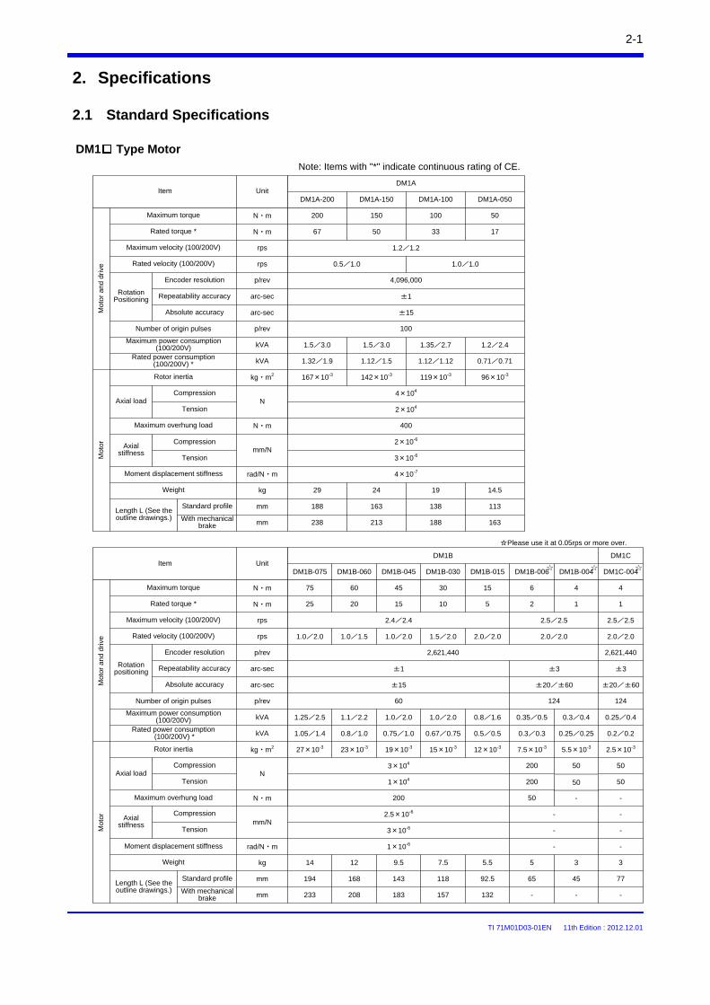
2. Specifications
2.1 Standard Specifications
DM1 Type Motor
Note: Items with "*" indicate continuous rating of CE.
arc-sec
Compression
Tension
Compression
Tension
Compression
Tension
Unit
Weight
Length L (See the outline drawings.)
Standard profile
With mechanical brake
Mo
tor
Mot
or
and
driv
e
Maximum power consumption(100/200V)
Rated power consumption(100/200V) *
TI 71M01D03-01EN 11th Edition : 2012.12.01
2-2
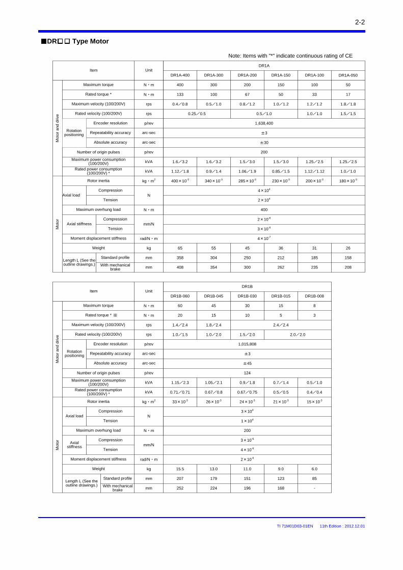
DR Type Motor
Note: Items with "*" indicate continuous rating of CE
DR1A
DR1A-400 DR1A-300
400 300
0.25/0.5
DR1A-200 DR1A-150
200 150
0.5/1.0
Rotation positioning
Item
Compression
Tension
Unit
arc-sec
rps
kg・m2
mm/N
N・m
N
mm
kg
rad/N・m
±3
4×10⁴
2×10⁴
400
2×10⁻⁶
3×10⁻⁶
4×10⁻⁷
230×10-3
36
212
285×10-3
45
250
340×10-3
55
304
400×10-3
65
358
Repeatability accuracy
Maximum torque
Rated velocity (100/200V)
Rotor inertia
Maximum overhung load
Moment displacement stiffness
Weight
Axial load
Axial stiffness
DR1A-100 DR1A-050
100 50
1.5/1.5
180×10-3
26
158
200×10-3
31
185
1.0/1.0
p/rev 1,638,400
N・m
Encoder resolution
Mo
tor
and
driv
e
arc-sec ±30Absolute accuracy
Mo
tor
Standard profile
With mechanical brake
Length L (See the outline drawings.)
mm 262300354408 208235
133 100 67 50Rated torque * 33 17N・m
0.4/0.8 0.8/1.2rpsMaximum velocity (100/200V) 1.8/1.81.2/1.20.5/1.0 1.0/1.2
1.6/3.2 1.5/3.0kVAMaximum power consumption(100/200V) 1.25/2.51.25/2.51.6/3.2 1.5/3.0
1.12/1.8 1.06/1.9kVARated power consumption(100/200V) * 1.0/1.01.12/1.120.9/1.4 0.85/1.5
p/rev 200Number of origin pulses
Rotation positioning
Item
Compression
Tension
Repeatability accuracy
Unit
arc-sec
p/rev
rps
kg・m2
mm/N
N・m
N
mm
kg
rad/N・m
Maximum torque
Rated velocity (100/200V)
DR1B-060
60
1.0/1.5
33×10-3
15.5
207
DR1B-045
45
1.0/2.0
26×10-3
13.0
179
DR1B-030
30
1.5/2.0
24×10-3
11.0
151
DR1B-015
15
21×10-3
9.0
123
DR1B-008
8
2.0/2.0
15×10-3
6.0
85
DR1B
124
±3
3×10⁴
1×10⁴
200
3×10⁻⁶
4×10⁻⁶
2×10⁻⁶
Rotor inertia
Maximum overhung load
Moment displacement stiffness
Weight
Axial load
Axial stiffness
Absolute accuracy arc-sec ±45
N・m
Number of origin pulses
Mo
tor
Mot
or
and
dri
ve
Standard profile
With mechanical brake
Length L (See the outline drawings.)
mm 252 224 196 168 -
Rated torque * 20 15 10 5 3N・m
rpsMaximum velocity (100/200V) 1.4/2.4 1.8/2.4 2.4/2.4
kVAMaximum power consumption(100/200V) 1.15/2.3 1.05/2.1 0.9/1.8 0.7/1.4 0.5/1.0
kVARated power consumption(100/200V) * 0.71/0.71 0.67/0.8 0.67/0.75 0.5/0.5 0.4/0.4
※
Encoder resolution
Compression
Tension
Compression
Tension
p/rev 1,015,808
TI 71M01D03-01EN 11th Edition : 2012.12.01
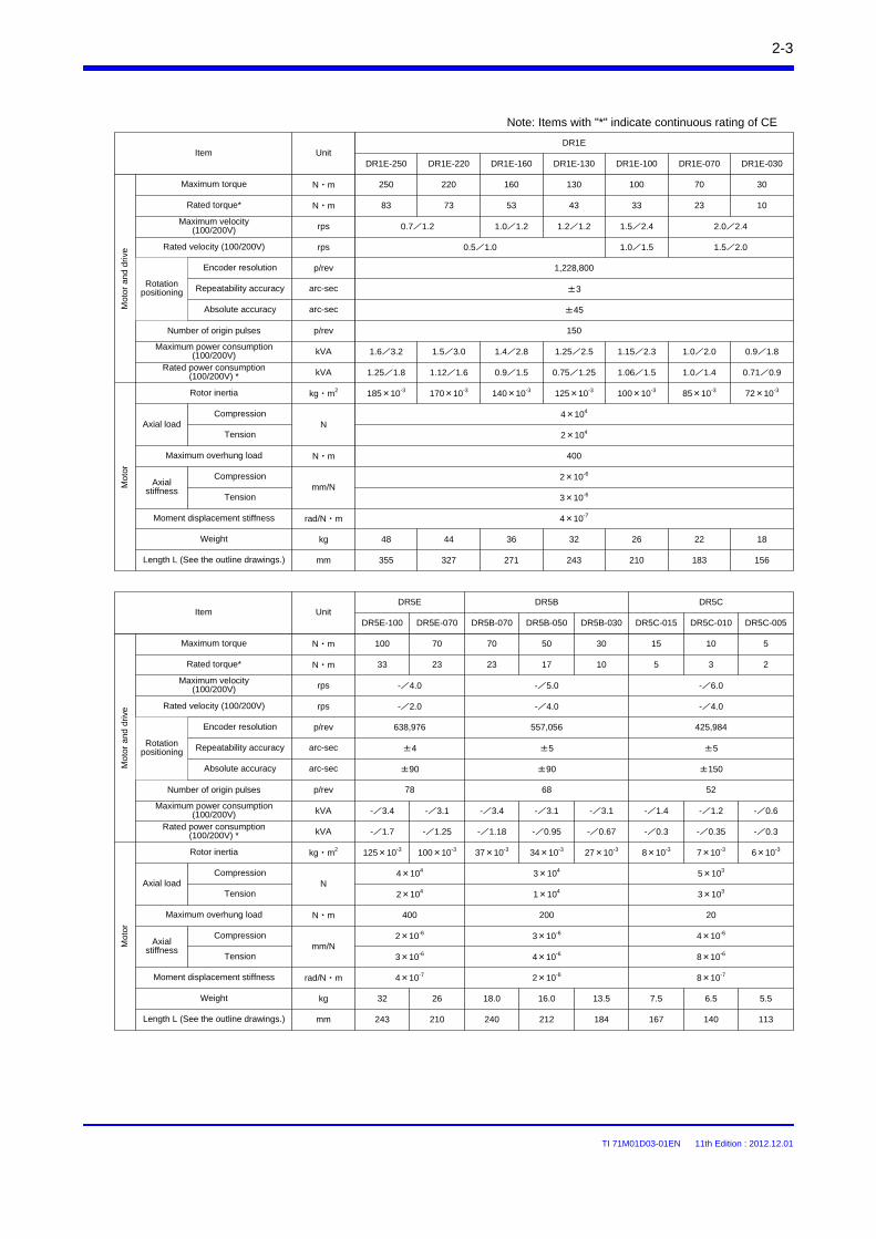
2-3
Note: Items with "*" indicate continuous rating of CE
DR5C-015
5
-/4.0
8×10⁻³
7.5
167
DR5C-010
3
7×10⁻³
6.5
140
DR5C-005
2
6×10⁻³
5.5
113
DR5C
425,984
±5
5×10³
3×10³
20
4×10⁻⁶
8×10⁻⁶
8×10⁻⁷
±150
Rotation positioning
Item
Compression
Tension
Unit
arc-sec
rps
kg・m2
mm/N
N・m
N
mm
kg
rad/N・m
Repeatability accuracy
Rated torque*
Rated velocity (100/200V)
Rotor inertia
Maximum overhung load
Moment displacement stiffness
Weight
Length L (See the outline drawings.)
Axial load
Axial stiffness
p/rev
arc-secAbsolute accuracy
N・m
Encoder resolution
DR5E
DR5E-100 DR5E-070
33 23
-/2.0
DR5B-070
23
37×10-3
18.0
240
100×10-3
26
210
125×10-3
32
243
DR5B-050 DR5B-030
17 10
27×10-3
13.5
184
34×10-3
16.0
212
DR5B
4×10⁴
±4
2×10⁴
400
2×10⁻⁶
3×10⁻⁶
4×10⁻⁷
638,976
3×10⁴
±5
1×10⁴
200
3×10⁻⁶
4×10⁻⁶
2×10⁻⁶
557,056
-/4.0
±90 ±90
15 10 5Maximum torque N・m 100 70 70 50 30
-/6.0rpsMaximum velocity (100/200V) -/4.0 -/5.0
kVAMaximum power consumption (100/200V) -/1.4 -/1.2 -/0.6-/3.4 -/3.1 -/3.4 -/3.1 -/3.1
kVARated power consumption(100/200V) * -/0.3 -/0.35 -/0.3-/1.7 -/1.25 -/1.18 -/0.95 -/0.67
52p/revNumber of origin pulses 78 68
Rotation positioning
Item
Compression
Tension
Repeatability accuracy
Unit
arc-sec
p/rev
rps
kg・m2
mm/N
N・m
N
mm
kg
rad/N・m
Rated torque*
Rated velocity (100/200V)
DR1E-250
83
0.5/1.0
185×10-3
48
355
DR1E-220
73
170×10-3
44
327
DR1E-160
53
140×10-3
36
271
DR1E-130
43
125×10-3
32
243
DR1E-100
33
1.0/1.5
100×10-3
26
210
DR1E
1,228,800
±3
4×10⁴
2×10⁴
400
2×10⁻⁶
3×10⁻⁶
4×10⁻⁷
Rotor inertia
Maximum overhung load
Moment displacement stiffness
Weight
Length L (See the outline drawings.)
Axial load
Axial stiffness
Absolute accuracy arc-sec ±45
N・m
Encoder resolution
23
1.5/2.0
85×10-3
22
183
10
72×10-3
18
156
DR1E-070 DR1E-030
Mot
or
and
driv
eM
oto
r
Maximum torque 250 220 160 130 100N・m 70 30
rpsMaximum velocity (100/200V) 0.7/1.2 1.5/2.4 2.0/2.41.0/1.2 1.2/1.2
kVAMaximum power consumption (100/200V) 1.6/3.2 1.15/2.3 1.0/2.01.4/2.8 1.25/2.51.5/3.0 0.9/1.8
kVARated power consumption(100/200V) * 1.25/1.8 1.06/1.5 1.0/1.40.9/1.5 0.75/1.251.12/1.6 0.71/0.9
p/rev 150Number of origin pulses
Compression
Tension
Compression
Tension
Mot
or
Mo
tor
and
driv
e
TI 71M01D03-01EN 11th Edition : 2012.12.01
2-4
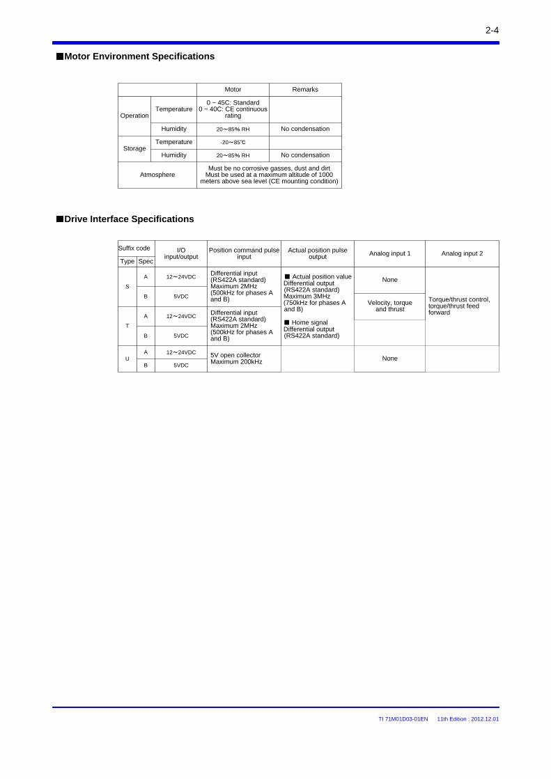
Motor Environment Specifications
Drive Interface Specifications
Position command pulse input
I/O input/output
Type
S
Differential input (RS422A standard)Maximum 2MHz(500kHz for phases A and B)
T
U
Actual position pulse output
12~24VDC
5V open collectorMaximum 200kHz
Actual position valueDifferential output (RS422A standard)Maximum 3MHz(750kHz for phases A and B)
Home signalDifferential output (RS422A standard)
5VDC
Analog input 2
Torque/thrust control, torque/thrust feed forward
12~24VDC
5VDC
12~24VDC
5VDC
Analog input 1
None
Velocity, torque and thrust
None
Spec
A
B
A
B
A
B
Suffix code
Differential input(RS422A standard)Maximum 2MHz(500kHz for phases A and B)
Operation
Motor
0 ~ 45C: Standard0 ~ 40C: CE continuous
rating
20~85% RH
Must be no corrosive gasses, dust and dirtMust be used at a maximum altitude of 1000
meters above sea level (CE mounting condition)Atmosphere
Storage
Temperature
Humidity
Temperature
Humidity
-20~85
20~85% RH
Remarks
No condensation
No condensation
TI 71M01D03-01EN 11th Edition : 2012.12.01
2-5
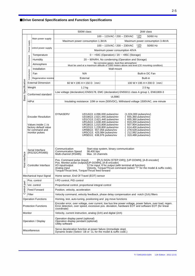
Drive General Specifications and Function Specifications
UL508C
Atmosphere No corrosive gases, dust-free atmosphere Must be used at a maximum altitude of 1000 meters above sea level (CE mounting condition)
Insulating resistance: 10M or more (500VDC), Withstand voltage 1500VAC, one minuteHiPot
DYNASERV UD1AG3; 4,096,000 pulses/rev (1,024,000 pulses/rev)UD1BG3; 2,621,440 pulses/rev ( 655,360 pulses/rev)UD1CG3; 2,621,440 pulses/rev ( 655,360 pulses/rev)UR1AG3; 1,638,400 pulses/rev ( 819,200 pulses/rev)UR1BG3; 1,015,808 pulses/rev ( 507,904 pulses/rev)UR1EG3; 1,228,800 pulses/rev ( 614,400 pulses/rev)UR5BG3; 557,056 pulses/rev ( 278,528 pulses/rev)UR5CG3; 425,984 pulses/rev ( 212,992 pulses/rev)UR5EG3; 638,976 pulses/rev ( 319,488 pulses/rev)
Bas
ic S
peci
ficat
ion
Main power supply
Control power supply
Encoder Resolution
Values inside ( ) is factory default value for command and monitor pulses
Humidity
100 ~ 115VAC / 200 ~ 230VAC
20 ~ 90%RH, No condensing (Operation and Storage)
Temperature 0 ~ +50C (Operation) / 20 ~ +85C (Storage)
N/A
Hos
t int
erfa
ce
Conformed standard
Installation
+10%-15%
Po
we
r su
pp
lyE
nviro
nm
ent
Fan
Co
nst
ruct
ion Wall-mount
Built-in DC Fan
External Dimension 60 W×195 H×150 D(mm) 100 W×195 H×200 D(mm)
Weight 1.2 kg 2.5 kg
Low voltage (declaration) EN50178, EMC (declaration) EN55011 class A group 1, EN61800-3
Con
trol
par
t
100 ~ 115VAC / 200 ~ 230VAC
Regenerative resistor External Built-in
500W class 2kW class
+10%-15%
Serial Interface (RS232C/RS485)
Communication Start-stop system, binary communicationCommunication Speed 38,400 bpsMulti-channel (RS485) Max. 10 channels
Controller Interface
Pos. control
Vel. control Proportional control, proportional integral control
I-PD control, PID control
Pos. Command pulse (input) [PLS-SIGN (STEP-DIR)], [UP-DOWN], [A-B encoder]Pos. Monitor pulse (output)[UP-DOWN], [A-B encoder]I/O input/output 12 for input, 6 for output (with terminal all function)Analog input Velocity, Torque/Thrust command (select "T" for the model & suffix code), Torque/Thrust limit, Torque/Thrust feed forward
Feed Forward Position, velocity, acceleration
Filter Velocity command, velocity feedback, phase delay compensation and notch (2ch) filters
Operation Functions Homing, test, auto-tuning, positioning and jog move functions
Protection FunctionsEncoder error, over voltage, over current, low bus line power voltage, power failure, over load, regen. Error detection, over speed, excessive pos. deviation, hardware EOT and software EOT (for linear coordinate)
Mechanical Input Signal Home sensor, End Of Travel (EOT) sensor
Velocity, current instruction, analog (2ch) and digital (2ch)Monitor
Operation / DisplayOperation display panel (optional)Operation display pendant (optional)Utility software
Miscellaneous Servo deceleration function at power failure (immediate stop)Dynamic brake (Select -1B or -1L for the model & suffix code.)
Maximum power consumption 40VA
Maximum power consumption 1.3kVA Maximum power consumption 3.4kVA
50/60 Hz
50/60 Hz
TI 71M01D03-01EN 11th Edition : 2012.12.01
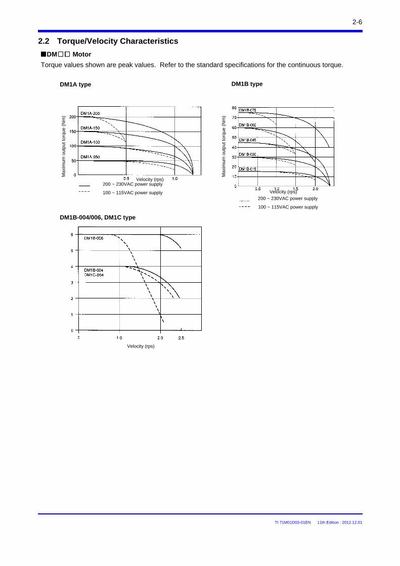
2-6
DM Motor
2.2 Torque/Velocity Characteristics
DM1A type DM1B type
DM1B-004/006, DM1C type
Torque values shown are peak values. Refer to the standard specifications for the continuous torque.M
axim
um o
utpu
t tor
que
(Nm
)
Max
imum
out
put t
orqu
e (N
m)
Velocity (rps)200 ~ 230VAC power supply
100 ~ 115VAC power supply200 ~ 230VAC power supply
100 ~ 115VAC power supply
Velocity (rps)
Velocity (rps)
TI 71M01D03-01EN 11th Edition : 2012.12.01
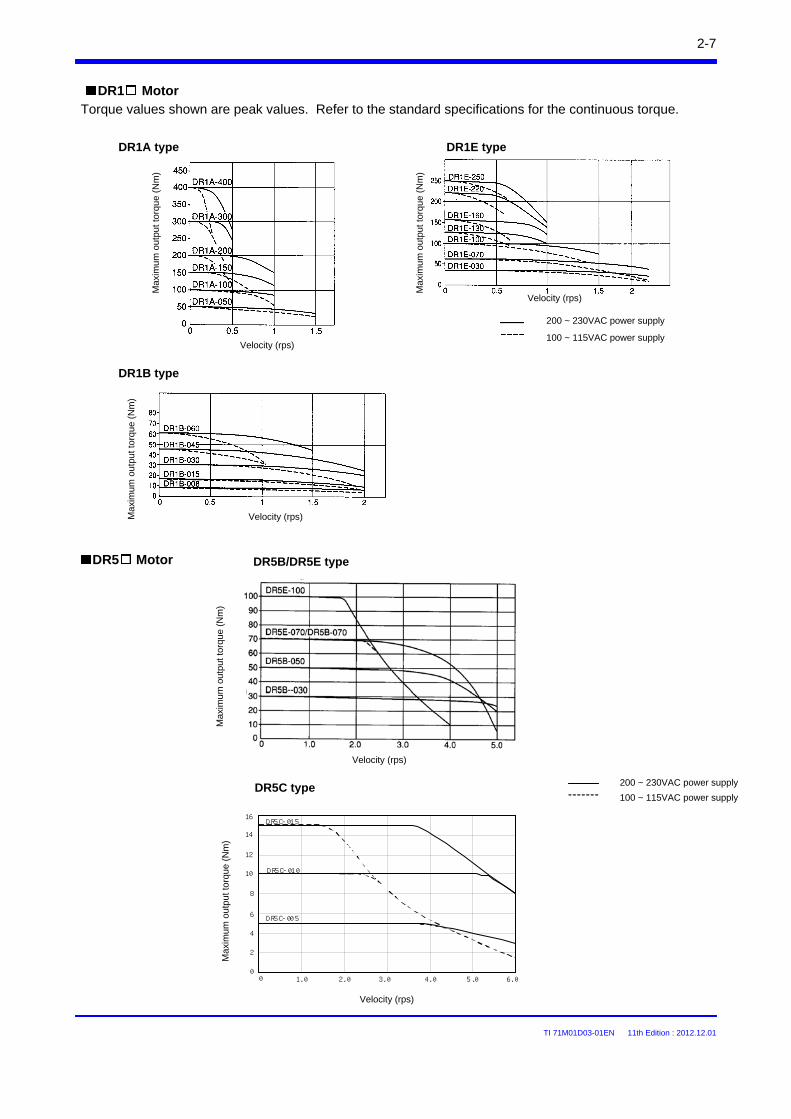
2-7
DR5 Motor
DR1 MotorTorque values shown are peak values. Refer to the standard specifications for the continuous torque.
DR1A type DR1E type
DR1B type
16
DR5C-015
DR5C-010
DR5C-005
0 1.0 2.0 3.0 4.0 5.0 6.0
2
4
6
8
10
12
14
16
0
Max
imum
out
put t
orqu
e (N
m)
Velocity (rps)
Max
imum
out
put t
orqu
e (N
m)
Velocity (rps)
200 ~ 230VAC power supply
100 ~ 115VAC power supply
Max
imum
out
put
torq
ue (
Nm
)
Velocity (rps)
Max
imum
out
put t
orqu
e (N
m)
Velocity (rps)
Max
imum
out
put t
orqu
e (N
m)
Velocity (rps)
200 ~ 230VAC power supply
100 ~ 115VAC power supply
DR5B/DR5E type
DR5C type
TI 71M01D03-01EN 11th Edition : 2012.12.01
2-8
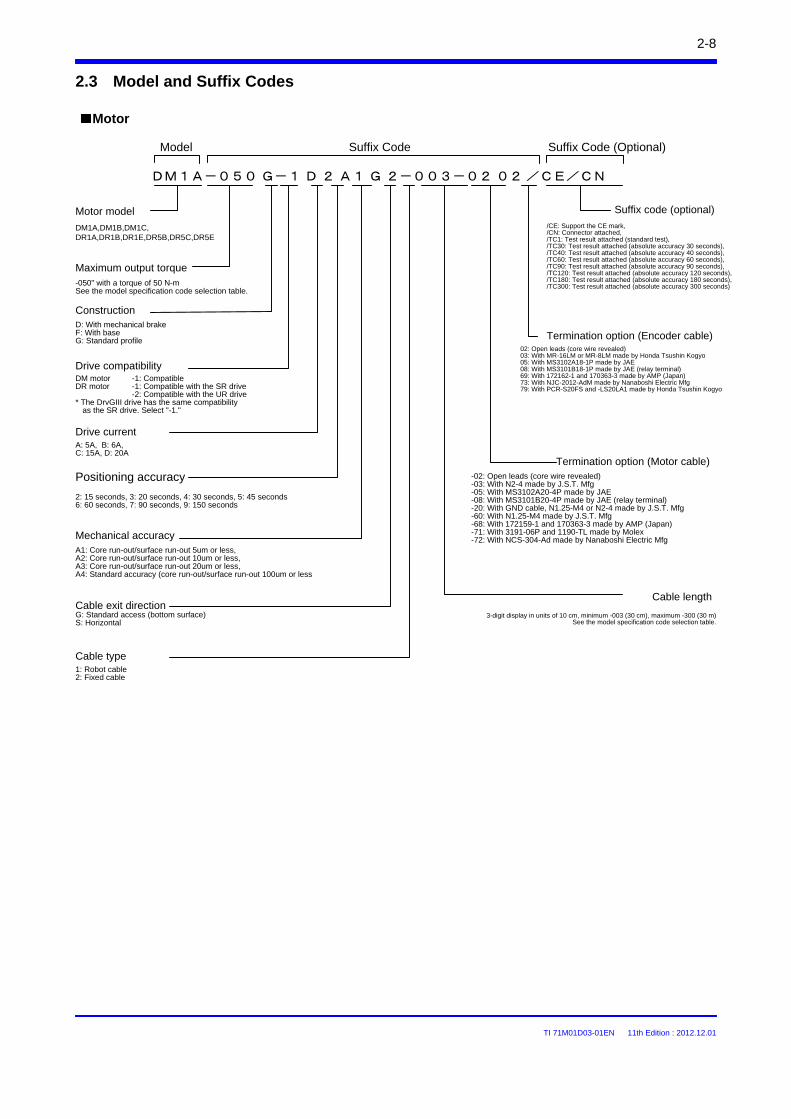
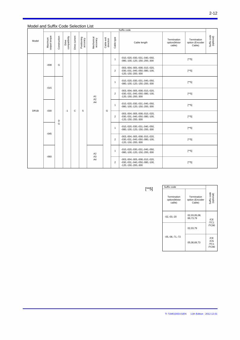
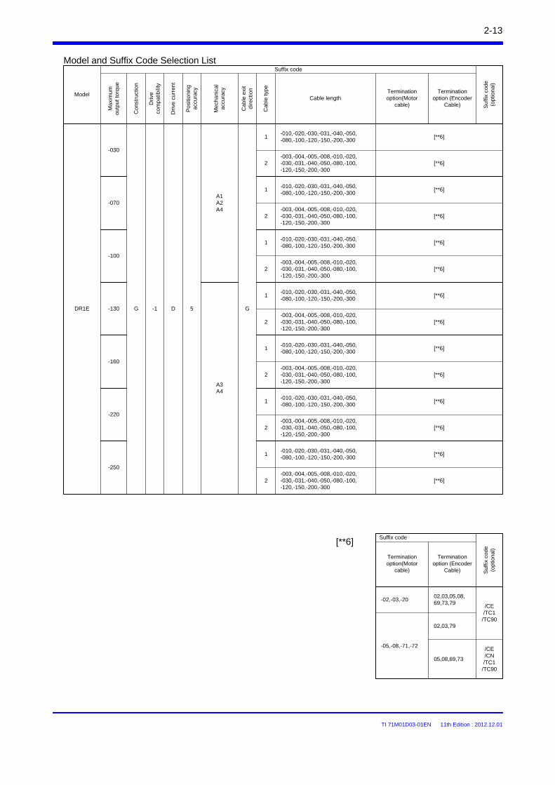
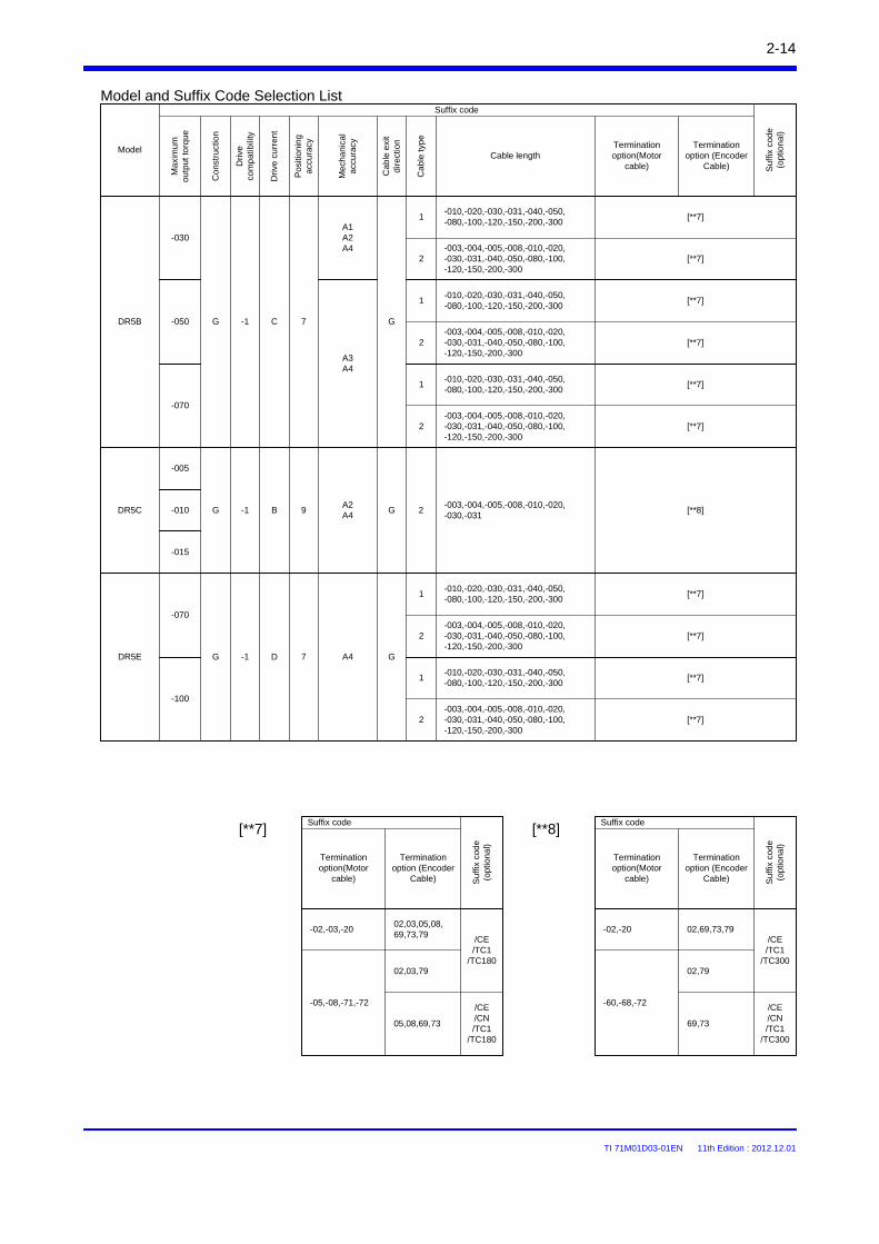
2.3 Model and Suffix Codes
Motor
DM1A-050 G-1 D 2 A1 G 2-003-02 02 /CE/CN
Model Suffix Code Suffix Code (Optional)
Motor model
DM1A,DM1B,DM1C,DR1A,DR1B,DR1E,DR5B,DR5C,DR5E
Maximum output torque-050" with a torque of 50 N-m See the model specification code selection table.
ConstructionD: With mechanical brakeF: With baseG: Standard profile
Drive compatibility
2: 15 seconds, 3: 20 seconds, 4: 30 seconds, 5: 45 seconds6: 60 seconds, 7: 90 seconds, 9: 150 seconds
Drive currentA: 5A, B: 6A,C: 15A, D: 20A
Mechanical accuracy
3-digit display in units of 10 cm, minimum -003 (30 cm), maximum -300 (30 m)See the model specification code selection table.
02: Open leads (core wire revealed)03: With MR-16LM or MR-8LM made by Honda Tsushin Kogyo05: With MS3102A18-1P made by JAE08: With MS3101B18-1P made by JAE (relay terminal)69: With 172162-1 and 170363-3 made by AMP (Japan)73: With NJC-2012-AdM made by Nanaboshi Electric Mfg79: With PCR-S20FS and -LS20LA1 made by Honda Tsushin Kogyo
Termination option (Encoder cable)
Suffix code (optional)
/CE: Support the CE mark,/CN: Connector attached,/TC1: Test result attached (standard test),/TC30: Test result attached (absolute accuracy 30 seconds),/TC40: Test result attached (absolute accuracy 40 seconds),/TC60: Test result attached (absolute accuracy 60 seconds),/TC90: Test result attached (absolute accuracy 90 seconds),/TC120: Test result attached (absolute accuracy 120 seconds),/TC180: Test result attached (absolute accuracy 180 seconds),/TC300: Test result attached (absolute accuracy 300 seconds)
DM motor -1: CompatibleDR motor -1: Compatible with the SR drive
-2: Compatible with the UR drive* The DrvGIII drive has the same compatibility
as the SR drive. Select "-1."
Positioning accuracy
A1: Core run-out/surface run-out 5um or less,A2: Core run-out/surface run-out 10um or less,A3: Core run-out/surface run-out 20um or less,A4: Standard accuracy (core run-out/surface run-out 100um or less
Termination option (Motor cable)-02: Open leads (core wire revealed)-03: With N2-4 made by J.S.T. Mfg-05: With MS3102A20-4P made by JAE-08: With MS3101B20-4P made by JAE (relay terminal)-20: With GND cable, N1.25-M4 or N2-4 made by J.S.T. Mfg-60: With N1.25-M4 made by J.S.T. Mfg-68: With 172159-1 and 170363-3 made by AMP (Japan)-71: With 3191-06P and 1190-TL made by Molex-72: With NCS-304-Ad made by Nanaboshi Electric Mfg
Cable exit directionG: Standard access (bottom surface)S: Horizontal
Cable type1: Robot cable2: Fixed cable
Cable length
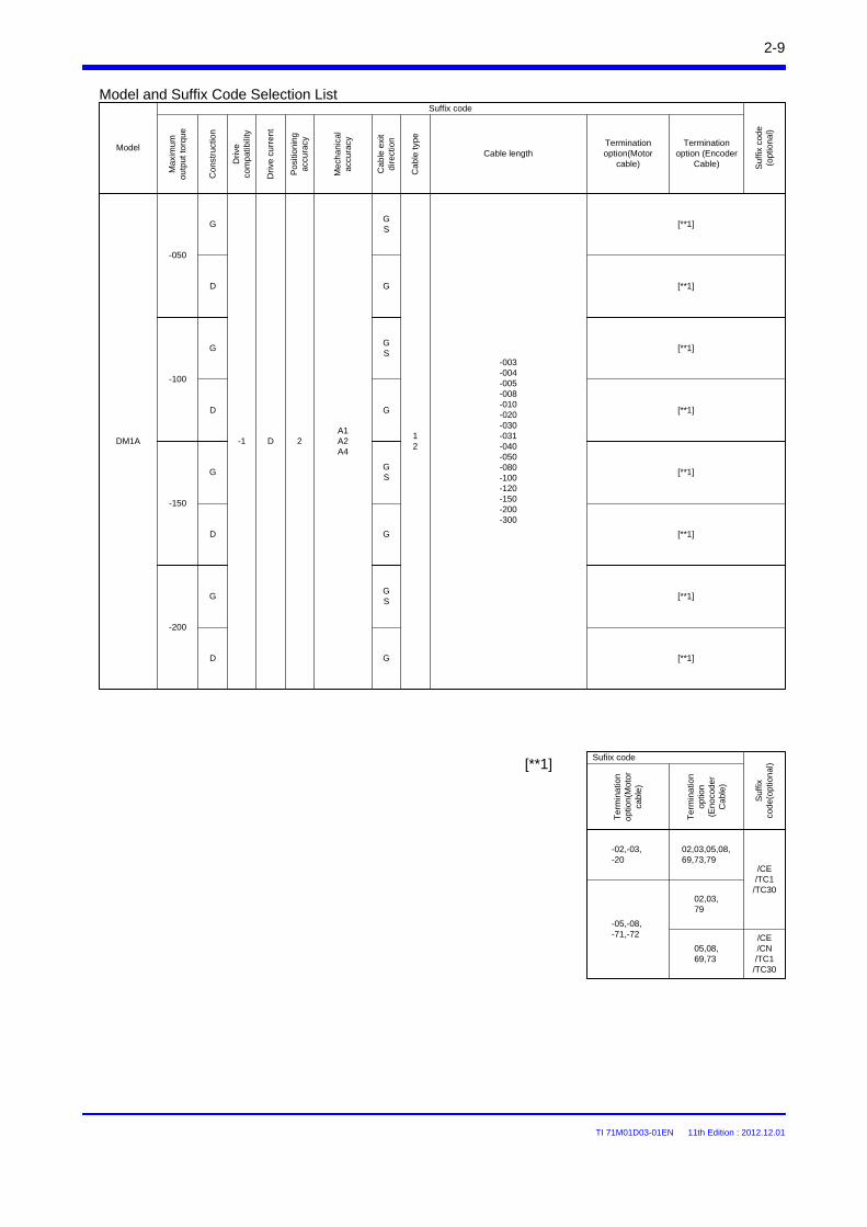
TI 71M01D03-01EN 11th Edition : 2012.12.01
Ma
xim
um
outp
ut
torq
ue
Con
stru
ctio
n
Driv
eco
mp
atib
ility
Dri
ve c
urr
ent
Pos
itio
nin
g
accu
racy
Mec
ha
nica
l ac
cura
cy
Ca
ble
exi
t di
rect
ion
Cab
le ty
pe
Cable lengthTermination option(Motor
cable)
Termination option (Encoder
Cable)
-050
[**1]
Model
Suf
fix c
ode
(opt
ion
al)
Suffix code
G
-1DM1A 2A1A2A4
D
GS
D G
-003-004-005-008-010-020-030-031-040-050-080-100-120-150-200-300
12
-100
GGS
D G
-150
GGS
D G
-200
GGS
D G
Model and Suffix Code Selection List
2-9
02,03,79
-05,-08,-71,-72
02,03,05,08,69,73,79
/CE/TC1
/TC30
-02,-03,-20
Sufiix code
05,08,69,73
/CE/CN/TC1
/TC30
[**1]
[**1]
[**1]
[**1]
[**1]
[**1]
[**1]
[**1]
Te
rmin
atio
n op
tion
(Mot
or
cabl
e)
Te
rmin
atio
n o
ptio
n (E
noco
de
r C
abl
e)
Suf
fix
code
(op
tion
al)
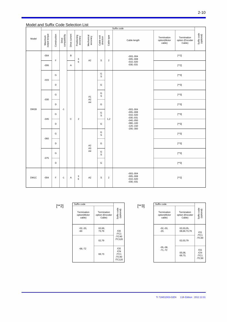
TI 71M01D03-01EN 11th Edition : 2012.12.01
-004 B
-006
DM1C -004 F A36
A2 S 2
-003,-004-005,-008-010,-020-030,-031
-003,-004-005,-008-010,-020-030,-031
S
A2A3A4
DM1B
F36
A2 2
A
-015
GGS
D G
-003,-004-005,-008-010,-020-030,-031-040,-050-080,-100-120,-150-200,-300
1,2
-1
C 2
A1A2A4
-030
GGS
D G
-045
GGS
D G
-060
GGS
D G
-075
GGS
D G
2-10
[**2]
[**3]
-1
02,79
-68,-72
02,69,73,79 /CE
/TC1/TC40
/TC120
-02,-20,-60
Suffix code
69,73
/CE/CN/TC1/TC40
/TC120
02,03,79
-05,-08,-71,-72
02,03,05,08,69,73,79
/CE/TC1
/TC30
-02,-03,-20,
Suffix code
05,08,69,73,
/CE/CN/TC1
/TC30
[**3][**2]
[**2]
[**3]
[**3]
[**3]
[**3]
[**3]
[**3]
[**3]
[**3]
[**3]
[**2]
Termination option(Motor
cable)
Termination option (Encoder
Cable) Suf
fix c
ode
(opt
ion
al)
Termination option(Motor
cable)
Termination option (Encoder
Cable) Suf
fix c
ode
(opt
ion
al)
Ma
xim
um
outp
ut
torq
ue
Con
stru
ctio
n
Driv
eco
mp
atib
ility
Dri
ve c
urr
ent
Pos
itio
nin
g
accu
racy
Mec
ha
nica
l ac
cura
cy
Ca
ble
exi
t di
rect
ion
Cab
le ty
pe
Cable lengthTermination option(Motor
cable)
Termination option (Encoder
Cable)
Model
Suf
fix c
ode
(opt
ion
al)
Suffix codeModel and Suffix Code Selection List
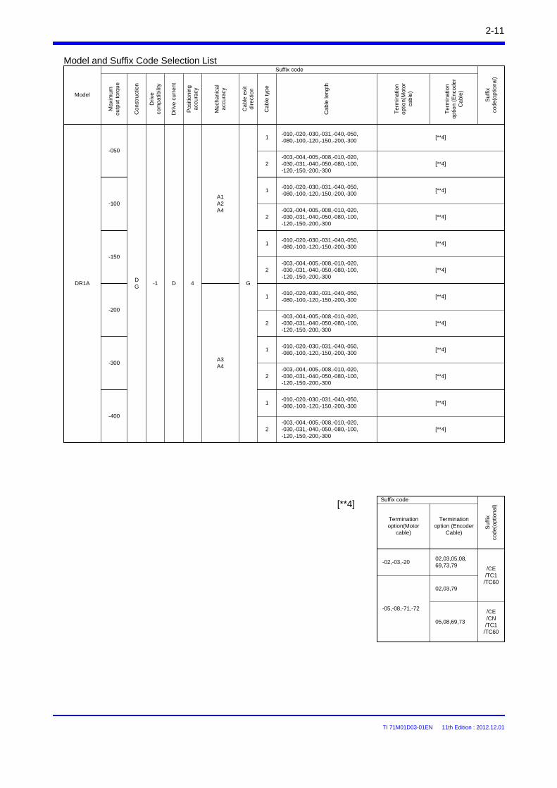
TI 71M01D03-01EN 11th Edition : 2012.12.01
-050
-100
-150
-200
-300
-400
G
A1A2A4
A3A4
D 4DR1ADG
-010,-020,-030,-031,-040,-050,-080,-100,-120,-150,-200,-300
1
-003,-004,-005,-008,-010,-020,-030,-031,-040,-050,-080,-100,-120,-150,-200,-300
2
-010,-020,-030,-031,-040,-050,-080,-100,-120,-150,-200,-300
1
-003,-004,-005,-008,-010,-020,-030,-031,-040,-050,-080,-100,-120,-150,-200,-300
2
-1
-010,-020,-030,-031,-040,-050,-080,-100,-120,-150,-200,-300
1
-003,-004,-005,-008,-010,-020,-030,-031,-040,-050,-080,-100,-120,-150,-200,-300
2
-010,-020,-030,-031,-040,-050,-080,-100,-120,-150,-200,-300
1
-003,-004,-005,-008,-010,-020,-030,-031,-040,-050,-080,-100,-120,-150,-200,-300
2
-010,-020,-030,-031,-040,-050,-080,-100,-120,-150,-200,-300
1
-003,-004,-005,-008,-010,-020,-030,-031,-040,-050,-080,-100,-120,-150,-200,-300
2
-010,-020,-030,-031,-040,-050,-080,-100,-120,-150,-200,-300
1
-003,-004,-005,-008,-010,-020,-030,-031,-040,-050,-080,-100,-120,-150,-200,-300
2
2-11
02,03,79
-05,-08,-71,-72
02,03,05,08,69,73,79
/CE/TC1
/TC60
-02,-03,-20
Suffix code
05,08,69,73
/CE/CN/TC1
/TC60
[**4]
[**4]
[**4]
[**4]
Ma
xim
um
outp
ut
torq
ue
Con
stru
ctio
n
Driv
eco
mp
atib
ility
Dri
ve c
urr
ent
Pos
itio
nin
g
accu
racy
Mec
ha
nica
l ac
cura
cy
Ca
ble
exi
t di
rect
ion
Cab
le ty
pe
Cab
le le
ngth
Ter
min
atio
n op
tion(
Mot
or
cabl
e)
Ter
min
atio
n o
ptio
n (
Enc
ode
r C
ab
le)
Model
Su
ffix
cod
e(op
tion
al)
Suffix codeModel and Suffix Code Selection List
[**4]
[**4]
[**4]
[**4]
[**4]
[**4]
[**4]
[**4]
[**4]
Termination option(Motor
cable)
Termination option (Encoder
Cable)
Su
ffix
cod
e(op
tion
al)
TI 71M01D03-01EN 11th Edition : 2012.12.01
-008
-015
-030
-045
-060
G
A1A2A4
A2A3A4
C 5DR1B
DG
-1
-010,-020,-030,-031,-040,-050,-080,-100,-120,-150,-200,-300
1
-003,-004,-005,-008,-010,-020,-030,-031,-040,-050,-080,-100,-120,-150,-200,-300
2
-010,-020,-030,-031,-040,-050,-080,-100,-120,-150,-200,-300
1
-003,-004,-005,-008,-010,-020,-030,-031,-040,-050,-080,-100,-120,-150,-200,-300
2
-010,-020,-030,-031,-040,-050,-080,-100,-120,-150,-200,-300
1
-003,-004,-005,-008,-010,-020,-030,-031,-040,-050,-080,-100,-120,-150,-200,-300
2
-010,-020,-030,-031,-040,-050,-080,-100,-120,-150,-200,-300
1
-003,-004,-005,-008,-010,-020,-030,-031,-040,-050,-080,-100,-120,-150,-200,-300
2
-010,-020,-030,-031,-040,-050,-080,-100,-120,-150,-200,-300
1
-003,-004,-005,-008,-010,-020,-030,-031,-040,-050,-080,-100,-120,-150,-200,-300
2
G
2-12
[**5]
02,03,79
-05,-08,-71,-72
02,03,05,08,69,73,79
/CE/TC1
/TC90
-02,-03,-20
Suffix code
05,08,69,73
/CE/CN/TC1
/TC90
[**5]
Ma
xim
um
outp
ut
torq
ue
Con
stru
ctio
n
Driv
eco
mp
atib
ility
Dri
ve c
urr
ent
Pos
itio
nin
g
accu
racy
Mec
ha
nica
l ac
cura
cy
Ca
ble
exi
t di
rect
ion
Cab
le ty
pe
Cable lengthTermination option(Motor
cable)
Termination option (Encoder
Cable)
Model
Suf
fix c
ode
(opt
ion
al)
Suffix codeModel and Suffix Code Selection List
[**5]
[**5]
[**5]
[**5]
[**5]
[**5]
[**5]
[**5]
[**5]
Termination option(Motor
cable)
Termination option (Encoder
Cable) Suf
fix c
ode
(opt
ion
al)
TI 71M01D03-01EN 11th Edition : 2012.12.01
-030
-070
-100
-130
-160
-220
G
A1A2A4
A3A4
D 5DR1E G -1
-010,-020,-030,-031,-040,-050,-080,-100,-120,-150,-200,-300
1
-003,-004,-005,-008,-010,-020,-030,-031,-040,-050,-080,-100,-120,-150,-200,-300
2
-010,-020,-030,-031,-040,-050,-080,-100,-120,-150,-200,-300
1
-003,-004,-005,-008,-010,-020,-030,-031,-040,-050,-080,-100,-120,-150,-200,-300
2
-010,-020,-030,-031,-040,-050,-080,-100,-120,-150,-200,-300
1
-003,-004,-005,-008,-010,-020,-030,-031,-040,-050,-080,-100,-120,-150,-200,-300
2
-010,-020,-030,-031,-040,-050,-080,-100,-120,-150,-200,-300
1
-003,-004,-005,-008,-010,-020,-030,-031,-040,-050,-080,-100,-120,-150,-200,-300
2
-010,-020,-030,-031,-040,-050,-080,-100,-120,-150,-200,-300
1
-003,-004,-005,-008,-010,-020,-030,-031,-040,-050,-080,-100,-120,-150,-200,-300
2
-010,-020,-030,-031,-040,-050,-080,-100,-120,-150,-200,-300
1
-003,-004,-005,-008,-010,-020,-030,-031,-040,-050,-080,-100,-120,-150,-200,-300
2
-250
-010,-020,-030,-031,-040,-050,-080,-100,-120,-150,-200,-300
1
-003,-004,-005,-008,-010,-020,-030,-031,-040,-050,-080,-100,-120,-150,-200,-300
2
2-13
02,03,79
-05,-08,-71,-72
02,03,05,08,69,73,79
/CE/TC1
/TC90
-02,-03,-20
Suffix code
05,08,69,73
/CE/CN/TC1
/TC90
[**6]
[**6]
[**6]
[**6]
[**6]
[**6]
[**6]
[**6]
[**6]
[**6]
[**6]
[**6]
[**6]
[**6]
Termination option(Motor
cable)
Termination option (Encoder
Cable) Su
ffix
code
(op
tion
al)
[**6]
Ma
xim
um
outp
ut
torq
ue
Con
stru
ctio
n
Driv
eco
mp
atib
ility
Dri
ve c
urr
ent
Pos
itio
nin
g
accu
racy
Mec
ha
nica
l ac
cura
cy
Ca
ble
exi
t di
rect
ion
Cab
le ty
pe
Cable lengthTermination option(Motor
cable)
Termination option (Encoder
Cable)
Model
Suf
fix c
ode
(opt
ion
al)
Suffix codeModel and Suffix Code Selection List
TI 71M01D03-01EN 11th Edition : 2012.12.01
-030
-050
-070
G
A1A2A4
C 7DR5B G -1
-010,-020,-030,-031,-040,-050,-080,-100,-120,-150,-200,-300
1
-003,-004,-005,-008,-010,-020,-030,-031,-040,-050,-080,-100,-120,-150,-200,-300
2
-010,-020,-030,-031,-040,-050,-080,-100,-120,-150,-200,-300
1
-003,-004,-005,-008,-010,-020,-030,-031,-040,-050,-080,-100,-120,-150,-200,-300
2
-010,-020,-030,-031,-040,-050,-080,-100,-120,-150,-200,-300
1
-003,-004,-005,-008,-010,-020,-030,-031,-040,-050,-080,-100,-120,-150,-200,-300
2
A3A4
-003,-004,-005,-008,-010,-020,-030,-031
-005
-010
-015
A2A4
DR5C B 9
7 A4DR5E D
-1 2
-070
-100
-1
-010,-020,-030,-031,-040,-050,-080,-100,-120,-150,-200,-300
1
-003,-004,-005,-008,-010,-020,-030,-031,-040,-050,-080,-100,-120,-150,-200,-300
2
-010,-020,-030,-031,-040,-050,-080,-100,-120,-150,-200,-300
1
-003,-004,-005,-008,-010,-020,-030,-031,-040,-050,-080,-100,-120,-150,-200,-300
2
GG
GG
2-14
02,03,79
-05,-08,-71,-72
02,03,05,08,69,73,79
/CE/TC1
/TC180
-02,-03,-20
Suffix code
05,08,69,73
/CE/CN/TC1
/TC180
[**7]
[**7]
[**7]
[**7]
[**7]
[**7]
[**7]
[**8]
02,79
-60,-68,-72
02,69,73,79/CE/TC1
/TC300
-02,-20
Suffix code
69,73
/CE/CN/TC1
/TC300
[**8]
[**7]
[**7]
[**7]
[**7]
Ma
xim
um
outp
ut
torq
ue
Con
stru
ctio
n
Driv
eco
mp
atib
ility
Dri
ve c
urr
ent
Pos
itio
nin
g
accu
racy
Mec
ha
nica
l ac
cura
cy
Ca
ble
exi
t di
rect
ion
Cab
le ty
pe
Cable lengthTermination option(Motor
cable)
Termination option (Encoder
Cable)
Model
Suf
fix c
ode
(opt
ion
al)
Suffix codeModel and Suffix Code Selection List
Termination option(Motor
cable)
Termination option (Encoder
Cable) Su
ffix
cod
e(o
ptio
nal)
Termination option(Motor
cable)
Termination option (Encoder
Cable) Su
ffix
cod
e(o
ptio
nal)
TI 71M01D03-01EN 11th Edition : 2012.12.01
2-15
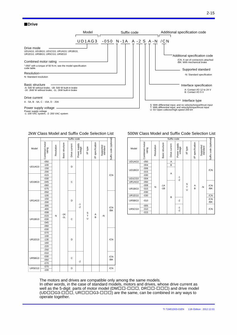
Drive
The motors and drives are compatible only among the same models.In other words, in the case of standard models, motors and drives, whose drive current as well as the 5-digit parts of motor model (DM-, DR-) and drive model (UDG3-, URG3-) are the same, can be combined in any ways to operate together.
2kW Class Model and Suffix Code Selection List 500W Class Model and Suffix Code Selection List
Model Suffix code Additional specification code
Drive modeUD1AG3, UD1BG3, UD1CG3, UR1AG3, UR1BG3,UR1EG3, UR5BG3, UR5CG3, UR5EG3
Combined motor rating"-050" with a torque of 50 N-m; see the model specification code table.
ResolutionN: Standard resolution
Basic structure-A: 500 W without brake, -1B: 500 W built-in brake-1K: 2kW W without brake, -1L: 2kW built-in brake
Drive currentA:5A, B:6A, C:15A, D:20A
Power supply voltagePower supply voltage-1: 100 VAC system, -2: 200 VAC system
Interface typeS: With differential input, and no velocity/torque/thrust inputT: With differential input, and velocity/torque/thrust inputU: 5V Open collector/high-speed 200 kH
Interface specificationA: Contact I/O 12 to 24 VB: Contact I/O 5 V
Supported standard
-N: Standard specification
Additional specification code/CN: A set of connectors attached/BK: With mechanical brake
/ C NU D 1 A G 3 - 0 5 0 - 1 AN A - 2 S - NA
-050
-100
-150
-200
-015
-030
-045
-060
-075
-050
-100
-150
-200
-300
-400
-008
-015
-030
-045
-060
-030
-070
-100
-130
-160
-220
-250
-010
-030
-050
-070
-070
-100
C
-1K-1L
C
D
UR1EG3
STU
UR5EG3 D
N
D
C
UR1BG3
D
-N
UR5BG3
-2
UD1AG3
-1-2
UR1AG3
UD1BG3
Com
bine
d m
oto
r ra
ting
Re
solu
tion
Bas
ic s
truc
ture
Dri
ve c
urr
en
t
Pow
er s
upp
ly
volta
ge
I/F
typ
e
I/F s
pec
ifica
tion
Su
ppo
rted
st
anda
rd
Model
Su
ffix
code
(o
ptio
nal
)
/CN
AB
/CN/BK
/CN
/CN/BK
/CN
Suffix code
UD1AG3 -050
-1A-1B
A
-1-2
-N
-004 B
-006
-015
-030
UD1CG3 -004
UR1AG3 -050
B
-008
-015
-030
UR1EG3 -030
UR5BG3 -010 -2
-005
-010
-015
UR5CG3-1-2
UR1BG3
UD1BG3
Model
A
Su
ffix
code
(o
ptio
nal
)
NSTU
AB
/CN
/CN/BK
/CN
/CN/BK
/CN
Com
bine
d m
oto
r ra
ting
Re
solu
tion
Bas
ic s
truc
ture
Dri
ve c
urr
en
t
Pow
er s
upp
ly
volta
ge
I/F
typ
e
I/F s
pec
ifica
tion
Su
ppo
rted
st
anda
rd
Suffix code
TI 71M01D03-01EN 11th Edition : 2012.12.01
2-16
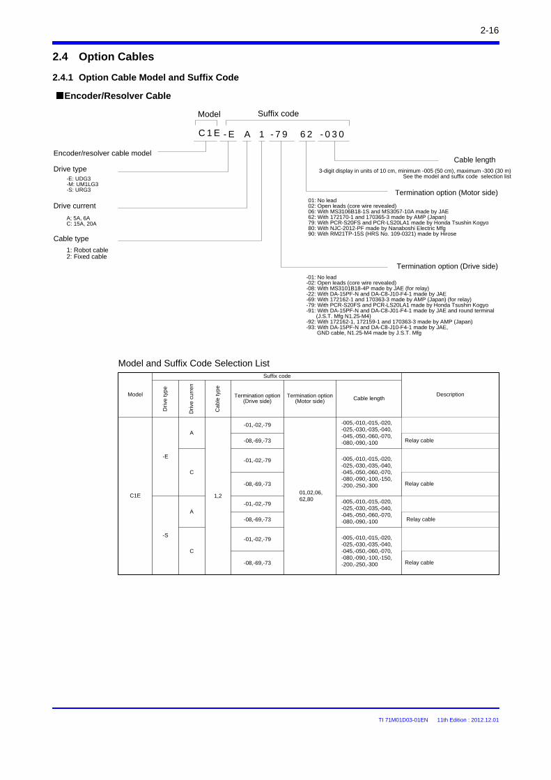
2.4 Option Cables
Encoder/Resolver Cable
Encoder/resolver cable model
Drive type-E: UDG3-M: UM1LG3-S: URG3
Drive current
Cable type
Termination option (Drive side)
Termination option (Motor side)
Cable length
3-digit display in units of 10 cm, minimum -005 (50 cm), maximum -300 (30 m)See the model and suffix code selection list
1: Robot cable2: Fixed cable
A; 5A, 6AC: 15A, 20A
Model and Suffix Code Selection List
2.4.1 Option Cable Model and Suffix Code
-01: No lead-02: Open leads (core wire revealed)-08: With MS3101B18-4P made by JAE (for relay)-22: With DA-15PF-N and DA-C8-J10-F4-1 made by JAE-69: With 172162-1 and 170363-3 made by AMP (Japan) (for relay)-79: With PCR-S20FS and PCR-LS20LA1 made by Honda Tsushin Kogyo-91: With DA-15PF-N and DA-C8-J01-F4-1 made by JAE and round terminal
(J.S.T. Mfg N1.25-M4)-92: With 172162-1, 172159-1 and 170363-3 made by AMP (Japan)-93: With DA-15PF-N and DA-C8-J10-F4-1 made by JAE,
GND cable, N1.25-M4 made by J.S.T. Mfg
01: No lead02: Open leads (core wire revealed)06: With MS3106B18-1S and MS3057-10A made by JAE62: With 172170-1 and 170365-3 made by AMP (Japan)79: With PCR-S20FS and PCR-LS20LA1 made by Honda Tsushin Kogyo80: With NJC-2012-PF made by Nanaboshi Electric Mfg90: With RM21TP-15S (HRS No. 109-0321) made by Hirose
Dri
ve ty
pe
Dri
ve c
urr
en
Ca
ble
typ
e
Termination option (Drive side)
Termination option (Motor side) Cable length
-01,-02,-79
01,02,06,62,80
-08,-69,-73 Relay cable
-01,-02,-79
-08,-69,-73 Relay cable
DescriptionModel
Suffix code
1,2
-005,-010,-015,-020,-025,-030,-035,-040,-045,-050,-060,-070,-080,-090,-100
C1E
-E
A
C
C 1 E
Model Suffix code
-005,-010,-015,-020,-025,-030,-035,-040,-045,-050,-060,-070,-080,-090,-100,-150,-200,-250,-300
-01,-02,-79
-08,-69,-73 Relay cable
-01,-02,-79
-08,-69,-73 Relay cable
-005,-010,-015,-020,-025,-030,-035,-040,-045,-050,-060,-070,-080,-090,-100
-S
A
C
-005,-010,-015,-020,-025,-030,-035,-040,-045,-050,-060,-070,-080,-090,-100,-150,-200,-250,-300
- 0 3 0- E A 1 - 7 9 6 2
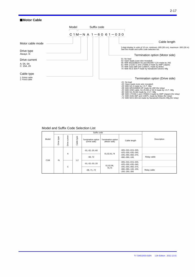
TI 71M01D03-01EN 11th Edition : 2012.12.01
2-17
Motor Cable
-01,-02,-20,-60
01,02,61,74
-68,-72 Relay cable
-01,-02,-03,-20
-08,-71,-72
01,02,06,70,74
Relay cable
C1M
A
-005,-010,-015,-020,-025,-030,-035,-040,-045,-050,-060,-070,-080,-090,-100,
-N 1,2
C
Model and Suffix Code Selection List
C1M-N A 1-60 61-030
Model Suffix code
Motor cable mode
Always -N
Cable type
Termination option (Drive side)-01: No lead-02: Open leads (core wire revealed)-03: With N2-4 made by J.S.T. Mfg-08: With MS3106B20-4P made by JAE (for relay)-20: With GND cable, N1.25-M4 or N2-4 made by J.S.T. Mfg-60: With N1.25-M4 made by J.S.T. Mfg-68: With 172159-1 and 170364-3 made by AMP (Japan) (for relay)-71: With 3191-06P and 1190TL made by Molex (for relay)-72: With NCS-304-Ad made by Nanaboshi Electric Mfg (for relay)
Termination option (Motor side)
Cable length
3-digit display in units of 10 cm, minimum -005 (50 cm), maximum -300 (30 m)See the model and suffix code selection list.
1: Robot cable2: Fixed cable
A; 5A, 6AC: 15A, 20
01: No lead02: Open leads (core wire revealed)06: With MS3106B20-4S and MS3057-12A made by JAE61: With 172167-1 and 170366-3 made by AMP (Japan)70: With 3191-06R and 1189ATL made by Molex74: With NCS-304-P made by Nanaboshi Electric Mfg
Drive type
Drive currentD
rive
typ
e
Dri
ve c
urr
en
Cab
le ty
pe
Termination option (Drive side)
Termination option (Motor side) Cable length
DescriptionModel
Suffix code
-005,-010,-015,-020,-025,-030,-035,-040,-045,-050,-060,-070,-080,-090,-100,-150,-200,-250,-300
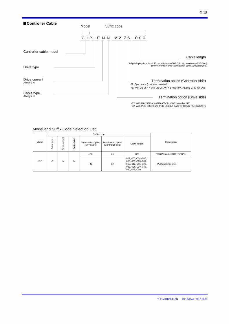
TI 71M01D03-01EN 11th Edition : 2012.12.01
2-18
Controller Cable
C1P-E N N-22 76-020
Model Suffix code
Controller cable model
Cable typeAlways N Termination option (Drive side)
02: Open leads (core wire revealed)
76: With DE-9SF-N and DE-C8-J9-F4-1 made by JAE (RS-232C for DOS)
Termination option (Controller side)
Cable length
3-digit display in units of 10 cm, minimum -002 (20 cm), maximum -050 (5 m)See the model name specification code selection table.
-22: With DA-15PF-N and DA-C8-J01-F4-1 made by JAE-42: With PCR-S36FS and PCR-LS36LA made by Honda Tsushin Kogyo
Drive type
Drive currentAlways N
Model and Suffix Code Selection List
C1P N-E N
Dri
ve t
ype
Dri
ve c
urr
ent
Ca
ble
type
Termination option (Drive side)
Termination option (Controller side) Cable length
DescriptionModel
Suffix code
PLC cable for CN4
-020
02-42
-22 76 RS232C cable(DOS) for CN1
-002,-003,-004,-005,-006,-007,-008,-009,-010,-012,-015,-020,-022,-025,-030,-035,-040,-045,-050,
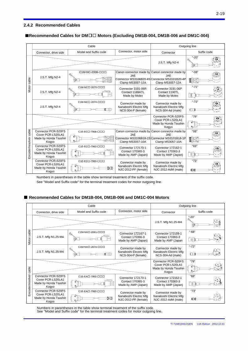
TI 71M01D03-01EN 11th Edition : 2012.12.01
2-19
Recommended Cables for DM Motors (Excluding DM1B-004, DM1B-006 and DM1C-004)
Recommended Cables for DM1B-004, DM1B-006 and DM1C-004 Motors
Mot
or c
able
J.S.T. Mfg N1.25-M4
J.S.T. Mfg N1.25-M4
J.S.T. Mfg N1.25-M4Connector made by
Nanaboshi Electric MfgNCS-304-Ad (male)
“-20”
“-68”
“-72”C1M-NA-2074-
C1M-NA-2061-
Connector made by Nanaboshi Electric Mfg
NCS-304-P (female)
Enc
oder
/res
olve
r ca
ble
Connector PCR-S20FSCover PCR-LS20LA1
Made by Honda Tsushin Kogyo
Connector made by Nanaboshi Electric MfgNJC-2012-AdM (male)
Connector made by Nanaboshi Electric MfgNJC-2012-PF (female)
Connector PCR-S20FSCover PCR-LS20LA1
Made by Honda Tsushin Kogyo
Connector PCR-S20FSCover PCR-LS20LA1
Made by Honda Tsushin Kogyo
“79”
“69”
“73”
C1E-EA-7962-
C1E-EA-7980-
Connector 172170-1Contact 170365-3
Made by AMP (Japan)
Connector 172162-1Contact 170363-3
Made by AMP (Japan)
Connector 172167-1Contact 170366-3
Made by AMP (Japan)
Connector 172159-1Contact 170363-3
Made by AMP (Japan
Numbers in parentheses in the table show terminal treatment of the suffix code.
See "Model and Suffix code" for the terminal treatment codes for motor outgoing line.
ConnectorConnector, motor sideConnector, drive side
Cable
Suffix codeModel and Suffix code
Mot
or c
able
“-20”
J.S.T. Mfg N2-4
Canon connector made by JAE
Connector MS3101B20-4PClanp MS3057-12A
Canon connector made by JAE
Connector MS3106B20-4SClamp MS3057-12A
Connector made by Nanaboshi Electric Mfg
NCS-304-Ad (male)
J.S.T. Mfg N2-4
J.S.T. Mfg N2-4
“-08”
“-72”
C1M-NC-2006-
C1M-NC-2074- Connector made by Nanaboshi Electric Mfg
NCS-304-P (female)
Enc
oder
/res
olve
r ca
ble
Connector PCR-S20FSCover PCR-LS20LA1
Made by Honda Tsushin Kogyo
Connector made by Nanaboshi Electric MfgNJC-2012-AdM (male)
Canon connector made by JAE
Connector MS3106B18-1SClamp MS3057-10A
Connector made by Nanaboshi Electric MfgNJC-2012-PF (female)
Connector PCR-S20FSCover PCR-LS20LA1
Made by Honda Tsushin Kogyo
Connector PCR-S20FSCover PCR-LS20LA1
Made by Honda Tsushin Kogyo
“79”
“08”
“73”
Canon connector made by JAE
Connector MS3101B18-1PClamp MS3057-10A
C1E-EC-7906-
C1E-EC-7980-
Connector 3191-06PContact 1190TLMade by Molex
Connector 3191-06RContact 1189ATLMade by Molex
J.S.T. Mfg N2-4
“-71”C1M-NC-2070-
Connector 172170-1Contact 170365-3
Made by AMP (Japan)
Connector PCR-S20FSCover PCR-LS20LA1
Made by Honda Tsushin Kogyo
“69”Connector 172162-1
Contact 170363-3Made by AMP (Japan)
C1E-EC-7962-
Numbers in parentheses in the table show terminal treatment of the suffix code.See "Model and Suffix code" for the terminal treatment codes for motor outgoing line.
2.4.2 Recommended Cables
Outgoing line
ConnectorConnector, motor sideConnector, drive side
Cable
Suffix codeModel and Suffix code
Outgoing line
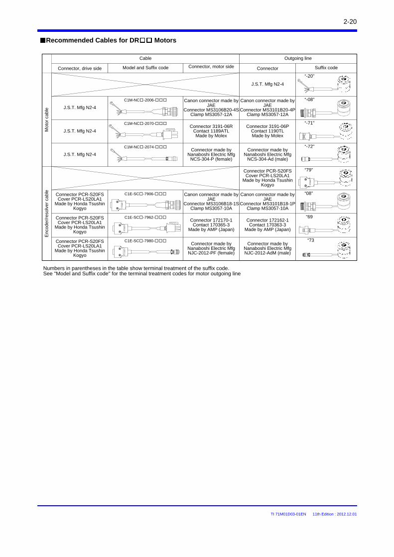
TI 71M01D03-01EN 11th Edition : 2012.12.01
2-20
Recommended Cables for DR MotorsM
otor
cab
le
“-20”
J.S.T. Mfg N2-4
Canon connector made by JAE
Connector MS3101B20-4PClamp MS3057-12A
Canon connector made by JAE
Connector MS3106B20-4SClamp MS3057-12A
Connector made by Nanaboshi Electric Mfg
NCS-304-Ad (male)
J.S.T. Mfg N2-4
J.S.T. Mfg N2-4
“-08”
“-72”
C1M-NC-2006-
C1M-NC-2074-Connector made by
Nanaboshi Electric MfgNCS-304-P (female)
Enc
oder
/res
olve
r ca
ble
Connector PCR-S20FSCover PCR-LS20LA1
Made by Honda Tsushin Kogyo
Connector made by Nanaboshi Electric MfgNJC-2012-AdM (male)
Canon connector made by JAE
Connector MS3106B18-1SClamp MS3057-10A
Connector made by Nanaboshi Electric MfgNJC-2012-PF (female)
Connector PCR-S20FSCover PCR-LS20LA1
Made by Honda Tsushin Kogyo
Connector PCR-S20FSCover PCR-LS20LA1
Made by Honda Tsushin Kogyo
“79”
“08”
“73
Canon connector made by JAE
Connector MS3101B18-1PClamp MS3057-10A
C1E-SC-7906-
C1E-SC-7980-
Connector 3191-06PContact 1190TLMade by Molex
Connector 3191-06RContact 1189ATLMade by Molex
J.S.T. Mfg N2-4
“-71”C1M-NC-2070-
Connector 172170-1Contact 170365-3
Made by AMP (Japan)
Connector PCR-S20FSCover PCR-LS20LA1
Made by Honda Tsushin Kogyo
“69Connector 172162-1
Contact 170363-3Made by AMP (Japan)
C1E-SC-7962-
Numbers in parentheses in the table show terminal treatment of the suffix code.See "Model and Suffix code" for the terminal treatment codes for motor outgoing line
ConnectorConnector, motor sideConnector, drive side
Cable
Suffix codeModel and Suffix code
Outgoing line
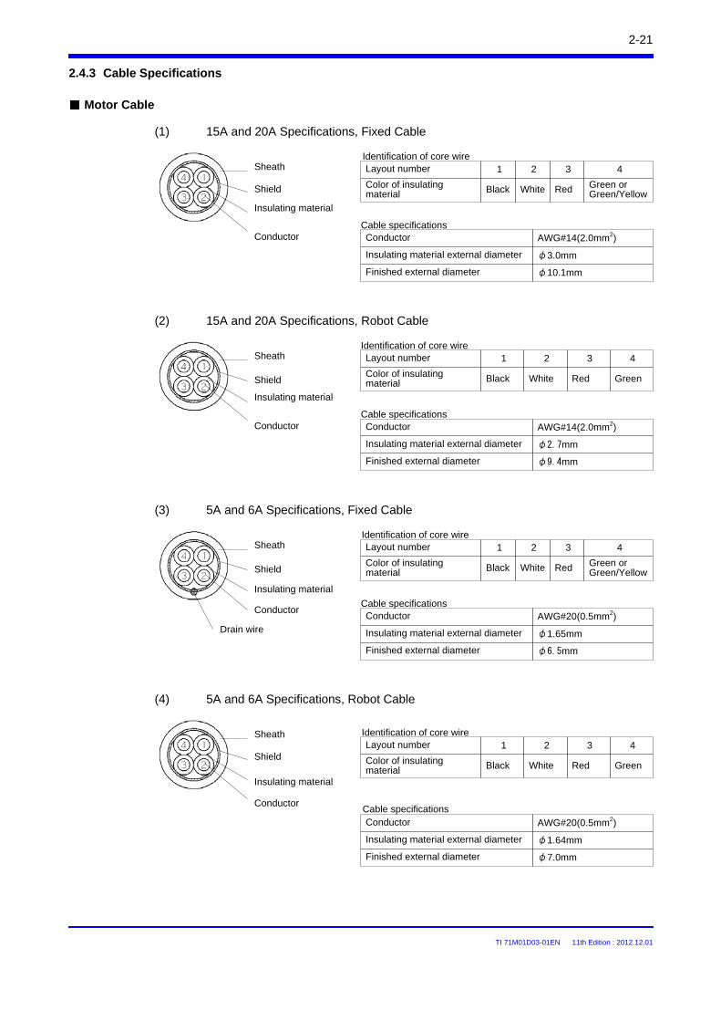
TI 71M01D03-01EN 11th Edition : 2012.12.01
2-21
Motor Cable
Layout number
2.4.3 Cable Specifications
(1) 15A and 20A Specifications, Fixed Cable
Identification of core wire
Color of insulating material
1 2 3 4
Black White Red Green or Green/Yellow
Conductor
AWG#14(2.0mm2)
Insulating material external diameter φ3.0mm
Finished external diameter φ10.1mm
Cable specifications
Conductor
Insulating material
Shield
Sheath
(2) 15A and 20A Specifications, Robot Cable
Identification of core wire1 2 3 4
AWG#20(0.5mm2)
Cable specifications
Conductor
Insulating material
Shield
Sheath
(3) 5A and 6A Specifications, Fixed Cable
(4) 5A and 6A Specifications, Robot Cable
AWG#20(0.5mm2)
φ1.64mm
φ7.0mm
Drain wire
Conductor
Insulating material
Shield
Sheath
Conductor
Insulating material
Shield
Sheath
Layout number
Color of insulating material Black White Red Green
Conductor
Insulating material external diameter
Finished external diameter
Layout numberIdentification of core wire
Color of insulating material
1 2 3 4
Black White Red Green or Green/Yellow
Conductor
Insulating material external diameter
Finished external diameter
Cable specifications
AWG#14(2.0mm2)
φ1.65mm
φ6.5mm
1 2 3 4Layout number
Color of insulating material Black White Red Green
Conductor
Insulating material external diameter
Finished external diameter
Identification of core wire
Cable specifications
φ2.7mm
φ9.4mm
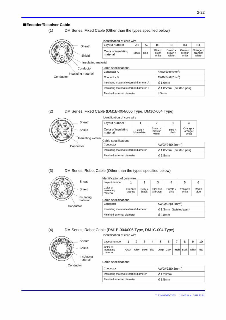
TI 71M01D03-01EN 11th Edition : 2012.12.01
2-22
Encoder/Resolver Cable
Layout number
Conductor
Insulating material
Shield
Sheath
(1) DM Series, Fixed Cable (Other than the types specified below)
Color of insulating material
A1 A2 B1 B2
Black RedBlue x blue/ white
Brown x brown /white
Conductor A AWG#20 (0.5mm2)
Insulating material external diameter B
Finished external diameter 8.5mm
Cable specifications
Layout number
Conductor
Insulating mterial
Shield
Sheath
(2) DM Series, Fixed Cable (DM1B-004/006 Type, DM1C-004 Type)
Identification of core wire
Color of insulating material
1 2 3 4
Red x black
Conductor AWG#24(0.2mm2)
Insulating material external diameter φ1.05mm(twisted pair)
Finished external diameter φ6.8mm
Cable specifications
Layout number
Conductor
Insulating material
Shield
SheathIdentification of core wire
Color of insulating material
1 2 3 4
Green x orange
Gray x black
Sky blue x brown
Purple x pink
Conductor AWG#22(0.3mm2)
Insulating material external diameter φ1.3mm(twisted pair)
Finished external diameter φ9.8mm
Cable specifications
Layout number
Conductor
Insulating material
Shield
Sheath
Identification of core wire
Color of insulating material
1 2 3 4
Green Yellow Brown Blue
Conductor AWG#22(0.3mm2)
Insulating material external diameter φ1.29mm
Finished external diameter φ8.5mm
Cable specifications
B3 B4
Green x green/ white
Orange x orange/ white
Conductor B AWG#24 (0.2mm2)
Insulating material external diameter A φ1.9mm
Insulating materialConductor
Blue x blue/white
Brown x brown/white
Orange x orange/white
(3) DM Series, Robot Cable (Other than the types specified below)
5 6 7 8 9 10
Orange Gray Purple Black White Red
(4) DM Series, Robot Cable (DM1B-004/006 Type, DM1C-004 Type)
5 6
Yellow x white
Red x blue
Identification of core wire
φ1.05mm(twisted pair)
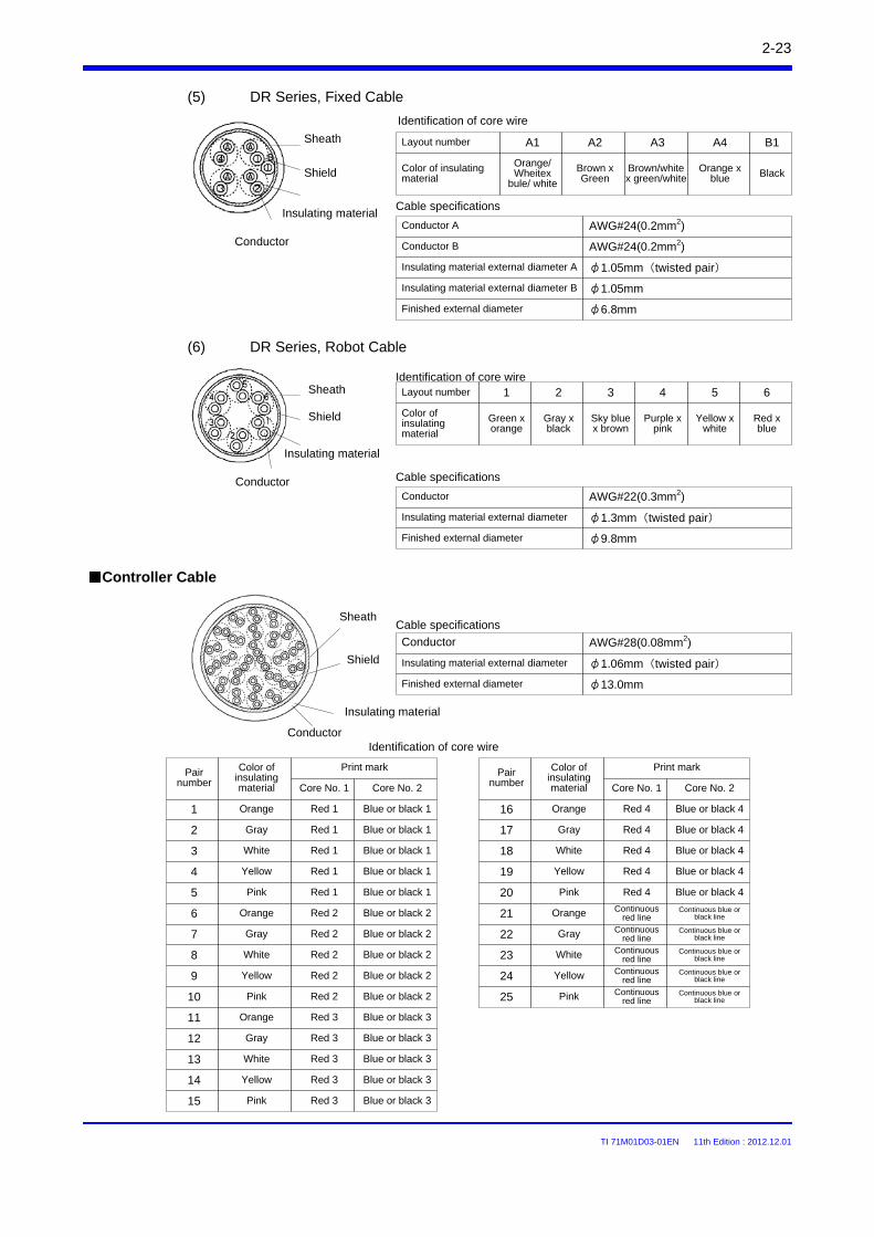
TI 71M01D03-01EN 11th Edition : 2012.12.01
2-23
Layout number
Conductor
Insulating material
Shield
Sheath
(5) DR Series, Fixed Cable
Identification of core wire
Color of insulating material
B1A1 A2
Black
Conductor A AWG#24(0.2mm2)
Insulating material external diameter B φ1.05mm
Finished external diameter φ6.8mm
Cable specifications
(6) DR Series, Robot Cable
A3 A4
Brown/white x green/white
Orange x blue
Conductor B AWG#24(0.2mm2)
Insulating material external diameter A φ1.05mm(twisted pair)
Layout number
Conductor
Insulating material
Shield
SheathIdentification of core wire
Color of insulating material
1 2 3 4
Green x orange
Gray x black
Sky blue x brown
Purple x pink
Conductor AWG#28(0.08mm2)
Insulating material external diameter φ1.06mm(twisted pair)
Finished external diameter φ13.0mm
Cable specifications
5 6
Yellow x white
Red x blue
Controller Cable
Conductor
Insulating material
Shield
Sheath
Conductor AWG#22(0.3mm2)
Insulating material external diameter φ1.3mm(twisted pair)
Finished external diameter φ9.8mm
Cable specifications
Pair number
Identification of core wire
1
Color of insulating material
Print mark
Orange
Core No. 1 Core No. 2
2
3
4
5
6
7
8
9
10
11
12
13
14
15
Gray
White
Yellow
Pink
Red 1 Blue or black 1
Red 2
Red 3
Red 3
Red 3
Red 3
Red 3
Pair number
16
Color of insulating material
Print mark
Core No. 1 Core No. 2
17
18
19
20
21
22
23
24
25
Red 4
Continuous red line
Continuous blue or black lineOrange
Gray
White
Yellow
Pink
Orange
Gray
White
Yellow
Pink
Red 1
Red 1
Red 1
Red 1
Red 2
Red 2
Red 2
Red 2
Blue or black 1
Blue or black 1
Blue or black 1
Blue or black 1
Blue or black 2
Blue or black 2
Blue or black 2
Blue or black 2
Blue or black 2
Blue or black 3
Blue or black 3
Blue or black 3
Blue or black 3
Blue or black 3
Red 4
Red 4
Red 4
Red 4
Continuous red line
Continuous red line
Continuous red line
Continuous red line
Blue or black 4
Blue or black 4
Blue or black 4
Blue or black 4
Blue or black 4
Orange
Gray
White
Yellow
Pink
Orange
Gray
White
Yellow
Pink
Continuous blue or black line
Continuous blue or black line
Continuous blue or black line
Continuous blue or black line
Orange/Wheitex
bule/ white
Brown x Green
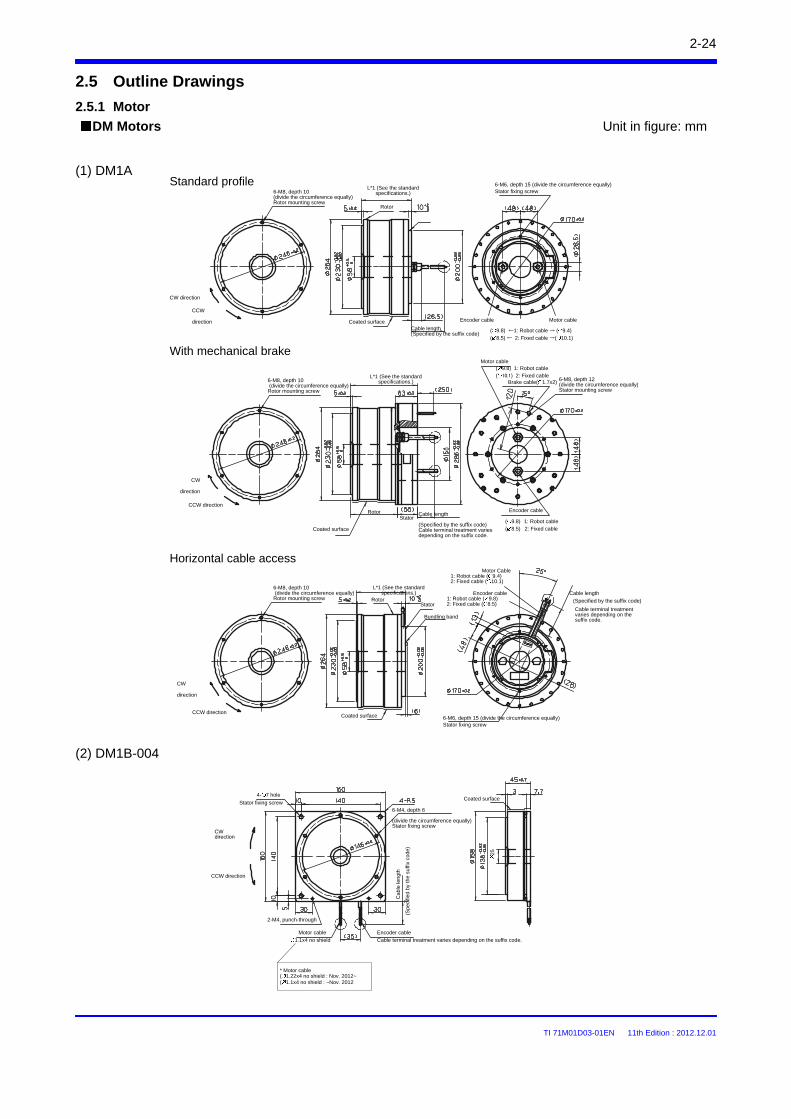
TI 71M01D03-01EN 11th Edition : 2012.12.01
2-24
2.5 Outline Drawings
DM Motors Unit in figure: mm
(1) DM1A
2.5.1 Motor
With mechanical brake
Horizontal cable access
(2) DM1B-004
Standard profile
CW direction
CCW
direction
6-M8, depth 10 (divide the circumference equally)Rotor mounting screw
L*1 (See the standard specifications.)
Rotor
Cable length(Specified by the suffix code)
Encoder cable Motor cable
( 9.8) ←1: Robot cable → ( 9.4)( 8.5) ← 2: Fixed cable →( 10.1)
CW
direction
CCW direction
6-M8, depth 10(divide the circumference equally)
Rotor mounting screw
L*1 (See the standard specifications.)
Coated surface
Coated surface
Stator
Motor cable( 9.8) 1: Robot cable ( 10.1) 2: Fixed cable
Brake cable( 1.7x2) 6-M8, depth 12 (divide the circumference equally)Stator mounting screw
Cable length
(Specified by the suffix code) Cable terminal treatment varies depending on the suffix code.
Encoder cable
( 9.8) 1: Robot cable ( 8.5) 2: Fixed cable
CW
direction
CCW direction
6-M8, depth 10(divide the circumference equally)
Rotor mounting screw
L*1 (See the standard specifications.)
Coated surface
Stator
Bundling band
6-M6, depth 15 (divide the circumference equally) Stator fixing screw
Encoder cable1: Robot cable ( 9.8)2: Fixed cable ( 8.5)
Motor Cable1: Robot cable ( 9.4)2: Fixed cable ( 10.1)
Cable terminal treatment varies depending on the suffix code.
Cable length
(Specified by the suffix code)
CW direction
CCW direction
4- 7 hole
Stator fixing screw
2-M4, punch-through
Motor cable
Cab
le le
ngt
h
(Spe
cifie
d b
y th
e su
ffix
code
)
Encoder cable
6-M4, depth 6
(divide the circumference equally) Stator fixing screw
Coated surface
Rotor
6-M6, depth 15 (divide the circumference equally) Stator fixing screw
Cable terminal treatment varies depending on the suffix code.1.1x4 no shield
25
Rotor
* Motor cable( 1.22x4 no shield : Nov. 2012~( 1.1x4 no shield : ~Nov. 2012
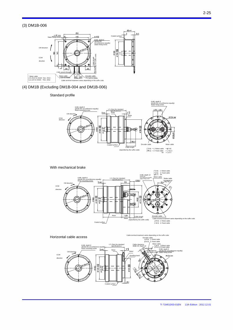
TI 71M01D03-01EN 11th Edition : 2012.12.01
2-25
(3) DM1B-006
Standard profile
With mechanical brake
Horizontal cable access
(4) DM1B (Excluding DM1B-004 and DM1B-006)
CW direction
CCW
direction
4- 7 holeStator fixing screw
6-M4, depth 6 (divide the circumference equally) Stator fixing screw
2-M4, punch-through
Motor cable Encoder cable
Cab
le le
ngt
h
(Spe
cifie
d by
the
suffi
x co
de)
Coated surface
CW direction
CCW direction
6-M6, depth 8 (divide the circumference equally) Rotor mounting screw
L*1 (See the standard specifications.)Rotor
Coated surface
Cable terminal treatment varies depending on the suffix code.
(Specified by the suffix code)
Encoder cable Motor cable
6-M6, depth 8(divide the circumference equally)Stator fixing screw
CW direction
CCW
direction
6-M6, depth 8 (divide the circumference equally) Rotor mounting screw
L*1 (See the standard specifications.)
Coated surface
Rotor
StatorCable length
6-M6, depth 12 (divide the circumference equally) Stator fixing screw
Motor cable
( 9.4) 1:Robot cable( 10.1) 2:Fixed cable
Brake cable
Encoder cable
Coated surface
CW direction
CCW
direction
6-M6, depth 8 (divide the circumference equally) Rotor mounting screw
L*1 (See the standard specifications.)
RotorStator
Bundling band
Stator
Cable clearance Width 20, Depth 10
Cable terminal treatment varies depending on the suffix code.
( 9.8) 1: Robot cable ( 8.5) 2: Fixed cable
Encoder cable
Motor cable
(Specified by the suffix code)
Cable length 6-M6, depth 8 (divide the circumference equally)Stator fixing screw
( 9.8) 1: Robot cable ( 8.5) 2: Fixed cable ( 6.7) 5A
Cable length
(Specified by the suffix code)
1.1x8 no shield1.1x4 no shield
( 9.8) ←1: Robot cable →( 9.4)( 8.5) ←2: Fixed cable →( 10.1)
5A →( 6.7)
Cable terminal treatment varies depending on the suffix code.
( 9.8) 1: Robot cable ( 8.5) 2: Fixed cable
25
* Motor cable( 1.22x4 no shield : Nov. 2012~( 1.1x4 no shield : ~Nov. 2012
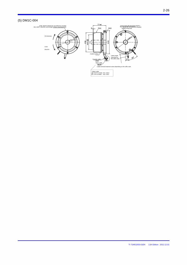
TI 71M01D03-01EN 11th Edition : 2012.12.01
2-26
(5) DM1C-004
6-M4, depth 6 (divide the circumference equally) HELI-SERT effective screw length 4 Rotor mounting screw
CW direction
CCW
direction
Coated surface
Motor cable
Cable terminal treatment varies depending on the suffix code.
Cable length
(Specified by the suffix code)
Rotor Stator
Encoder cable
(divide the circumference equally)Stator fixing hole
6- 4.5 hole 8 spot facing depth 5
25
* Motor cable( 1.22x4 no shield : Nov. 2012~( 1.1x4 no shield : ~Nov. 2012
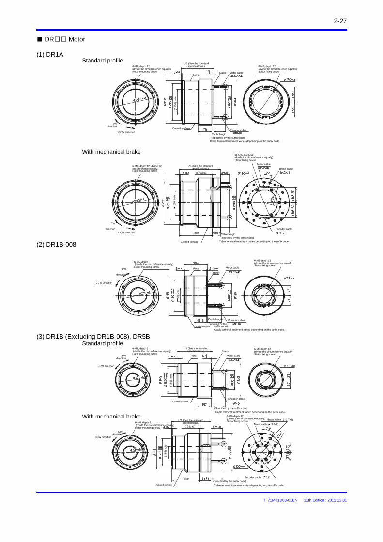
TI 71M01D03-01EN 11th Edition : 2012.12.01
2-27
DR Motor
(1) DR1A
(3) DR1B (Excluding DR1B-008), DR5B
(2) DR1B-008
Standard profile
With mechanical brake
Standard profile
With mechanical brake
L*1 (See the standard
specifications.)
Coated surfaceEncoder cable
Motor cable
6-M8, depth 12 (divide the circumference equally)Stator fixing screwStator
Cable length(Specified by the suffix code)
Rotor
Cable terminal treatment varies depending on the suffix code.
6-M8, depth 12 (divide the circumference equally) Rotor mounting screw
6-M8, depth 12 (divide the circumference equally)Rotor mounting screw
12-M8, depth 12 (divide the circumference equally)Stator fixing screw
CW
direction
CCW direction
Coated surface
Cable length(Specified by the suffix code)
Cable terminal treatment varies depending on the suffix code.
Motor cable
Brake cable
Encoder cable
L*1 (See the standard specifications.)
CW direction
CCW direction
Rotor
CW
direction
CCW direction
6-M5, depth 5(divide the circumference equally)
Rotor mounting screw
(15
0) h
ole
(15
0) h
ole
(56
) ho
le
Rotor Motor cable
Stator
6-M6 depth 12 (divide the circumference equally)Stator fixing screw
Cable length
(Specified by the suffix code)Cable terminal treatment varies depending on the suffix code.
Encoder cable
Coated surface
CW direction
CCW direction
6-M6, depth 9(divide the circumference equally)
Rotor mounting screw
L*1 (See the standard specifications.)
(56
) ho
le
Coated surface
(Specified by the suffix code)
Cable terminal treatment varies depending on the suffix code.
Stator
Motor cable
6-M6 depth 12 (divide the circumference equally)Stator fixing screw
CW direction
CCW direction
6-M6, depth 9(divide the circumference equally)Rotor mounting screw
(56
) h
ole
L*1 (See the standard specifications.)
Coated surface
Rotor
6-M6 depth 12 (divide the circumference equally)Stator fixing screw
(Specified by the suffix code)
Cable terminal treatment varies depending on the suffix code.
Brake cable
Motor cable
Encoder cable
( 1.7x2)
( 3.2x2)
( 6.8)
Encoder cable
Rotor
0.2 (gap)
0.2 (gap)
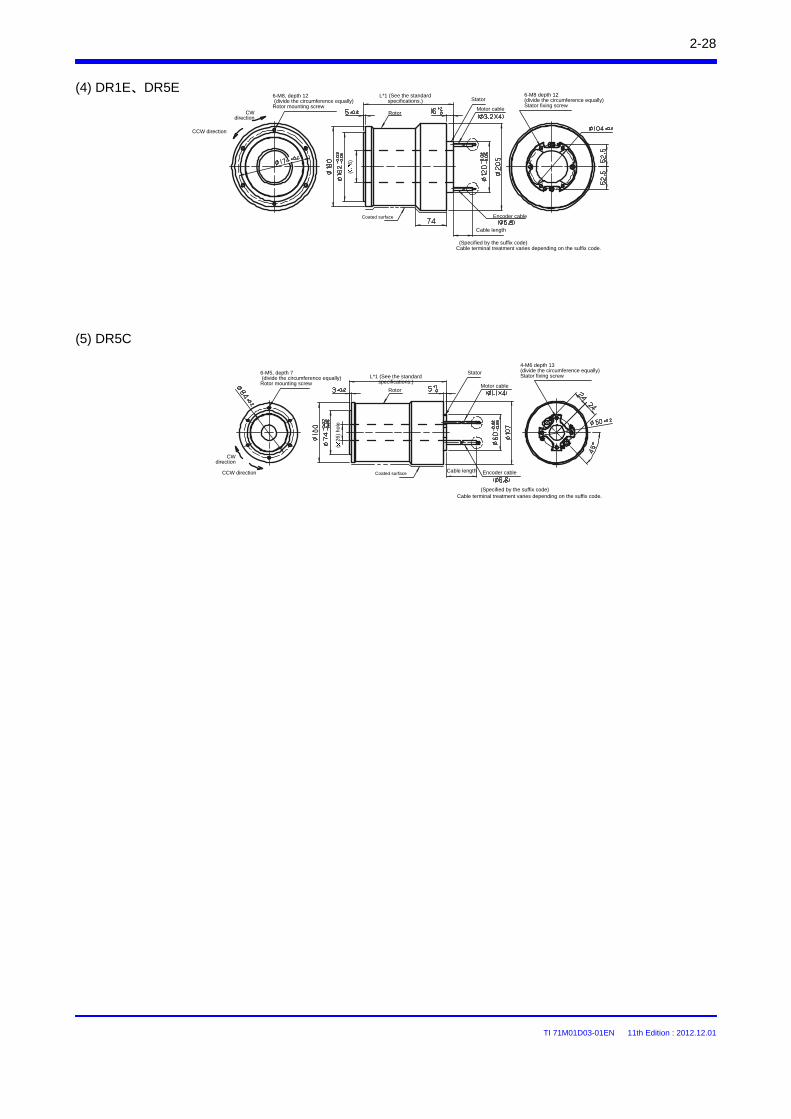
TI 71M01D03-01EN 11th Edition : 2012.12.01
2-28
(5) DR5C
(4) DR1E、DR5E
CW direction
CCW direction
6-M8, depth 12(divide the circumference equally)
Rotor mounting screw
L*1 (See the standard specifications.)
(6)
Coated surface
(Specified by the suffix code)Cable terminal treatment varies depending on the suffix code.
Stator
Motor cable
6-M8 depth 12 (divide the circumference equally)Stator fixing screw
Cable length
Encoder cable
CW direction
CCW direction
6-M5, depth 7(divide the circumference equally)Rotor mounting screw
L*1 (See the standard specifications.)
(26
) ho
le
Coated surface
(Specified by the suffix code)Cable terminal treatment varies depending on the suffix code.
Stator
Motor cable
4-M6 depth 13(divide the circumference equally)Stator fixing screw
Cable length Encoder cable
Rotor
Rotor
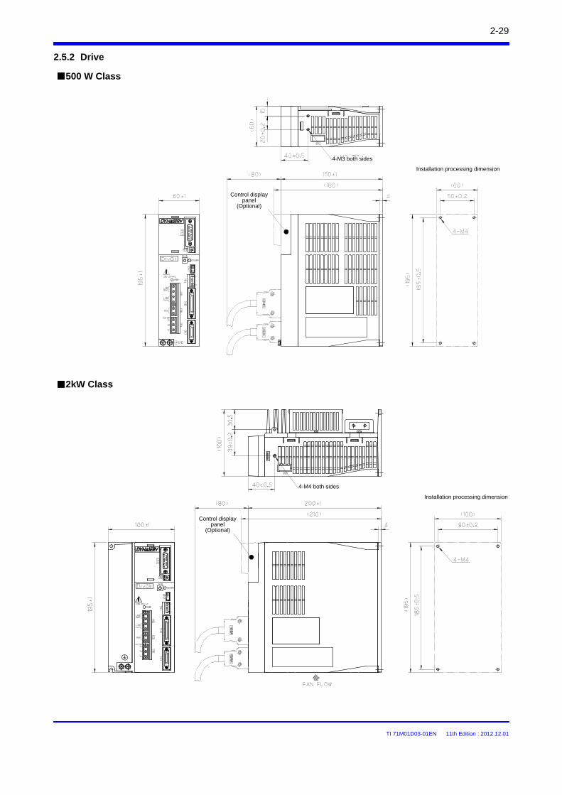
TI 71M01D03-01EN 11th Edition : 2012.12.01
2-29
2.5.2 Drive
500 W Class
2kW Class
Control display panel
(Optional)
Control display panel
(Optional)
Installation processing dimension
Installation processing dimension
4-M4 both sides
4-M3 both sides
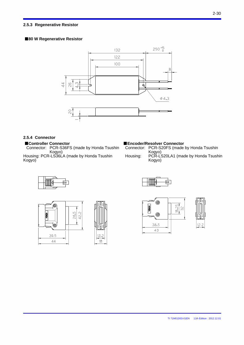
TI 71M01D03-01EN 11th Edition : 2012.12.01
2-30
2.5.3 Regenerative Resistor
80 W Regenerative Resistor
2.5.4 Connector
Controller ConnectorConnector: PCR-S36FS (made by Honda Tsushin
Kogyo)Housing: PCR-LS36LA (made by Honda Tsushin Kogyo)
Encoder/Resolver ConnectorConnector: PCR-S20FS (made by Honda Tsushin
Kogyo)Housing: PCR-LS20LA1 (made by Honda Tsushin
Kogyo)
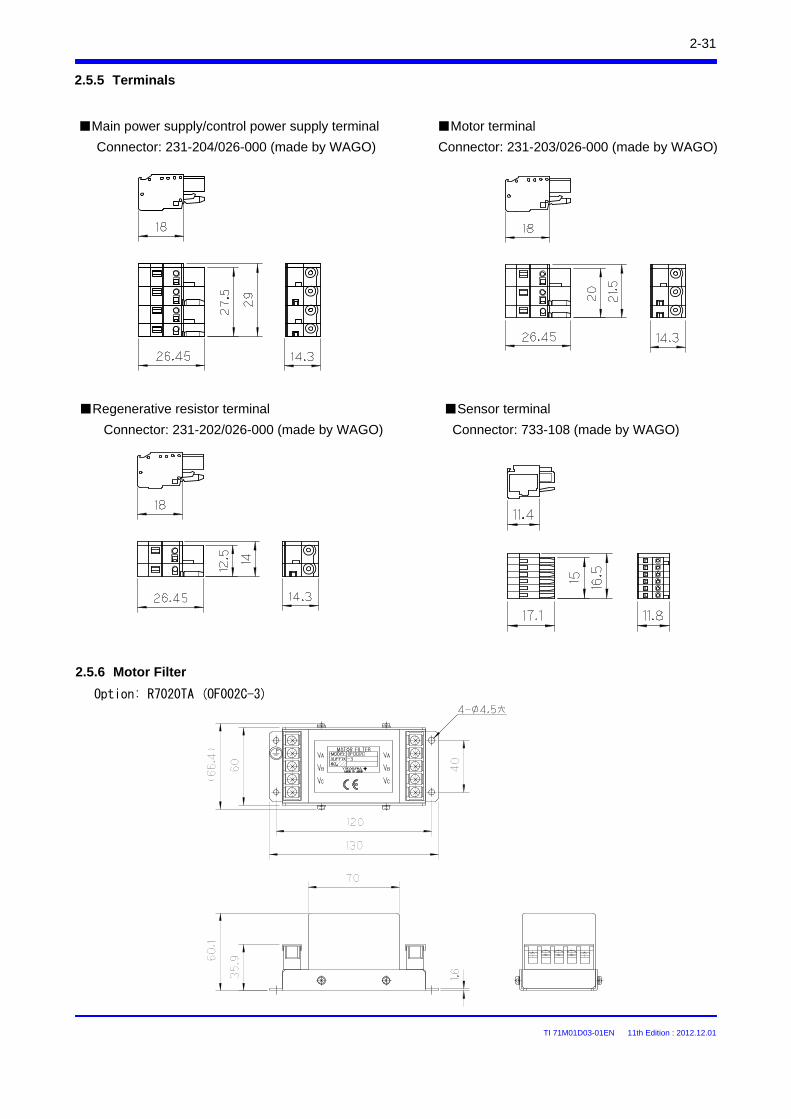
TI 71M01D03-01EN 11th Edition : 2012.12.01
Main power supply/control power supply terminal Motor terminal
Connector: 231-204/026-000 (made by WAGO) Connector: 231-203/026-000 (made by WAGO)
Connector: 231-202/026-000 (made by WAGO)
Sensor terminal
Connector: 733-108 (made by WAGO)
2.5.5 Terminals
2-31
Regenerative resistor terminal
2.5.6 Motor Filter
Option: R7020TA (OF002C-3)
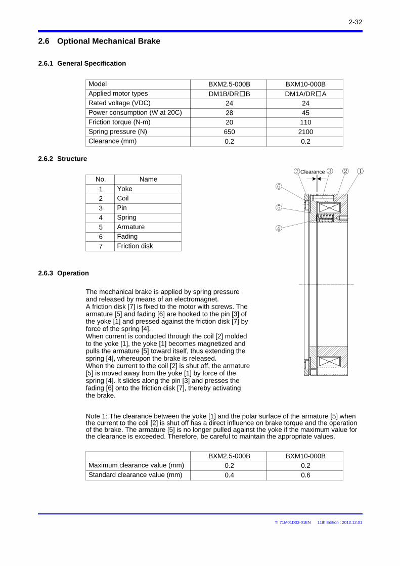
TI 71M01D03-01EN 11th Edition : 2012.12.01
2.6 Optional Mechanical Brake
2.6.1 General Specification
Model BXM2.5-000B
Power consumption (W at 20C)
Friction torque (N-m)
Applied motor types DM1B/DRBRated voltage (VDC) 24
BXM10-000B
DM1A/DRA
28
20
24
45
110Spring pressure (N)
Clearance (mm)650
0.2
2100
0.2
2.6.2 Structure
①②③⑦
⑥
⑤
④
No.
1
2
3
4
5
6
7
Name
Yoke
Coil
Pin
Spring
Armature
Fading
Friction disk
2.6.3 Operation
The mechanical brake is applied by spring pressure and released by means of an electromagnet. A friction disk [7] is fixed to the motor with screws. The armature [5] and fading [6] are hooked to the pin [3] of the yoke [1] and pressed against the friction disk [7] by force of the spring [4]. When current is conducted through the coil [2] molded to the yoke [1], the yoke [1] becomes magnetized and pulls the armature [5] toward itself, thus extending the spring [4], whereupon the brake is released. When the current to the coil [2] is shut off, the armature [5] is moved away from the yoke [1] by force of the spring [4]. It slides along the pin [3] and presses the fading [6] onto the friction disk [7], thereby activating the brake.
Note 1: The clearance between the yoke [1] and the polar surface of the armature [5] when the current to the coil [2] is shut off has a direct influence on brake torque and the operation of the brake. The armature [5] is no longer pulled against the yoke if the maximum value for the clearance is exceeded. Therefore, be careful to maintain the appropriate values.
BXM2.5-000B
Standard clearance value (mm)
Maximum clearance value (mm) 0.2
BXM10-000B
0.4
0.2
0.6
2-32
Clearance
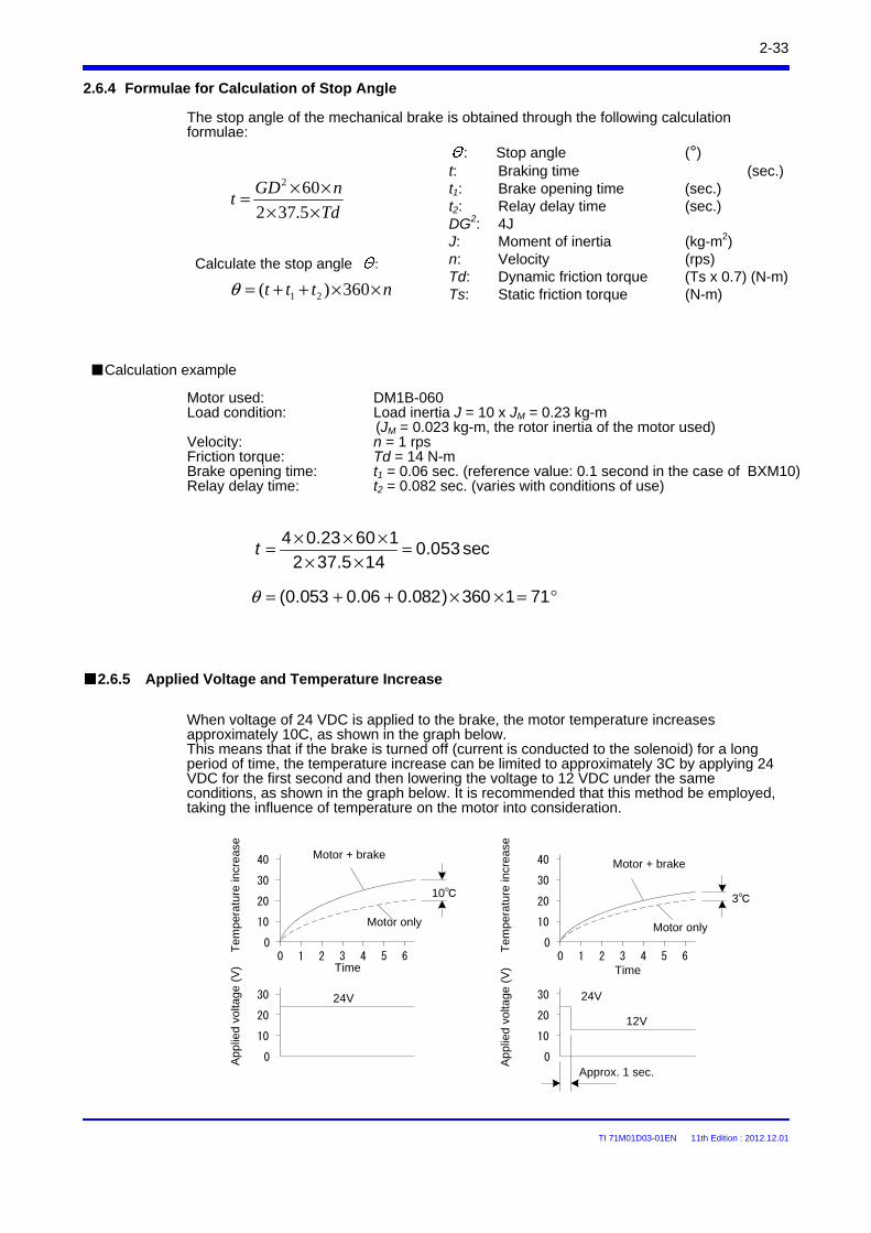
TI 71M01D03-01EN 11th Edition : 2012.12.01
2.6.4 Formulae for Calculation of Stop Angle
The stop angle of the mechanical brake is obtained through the following calculation formulae:
nttt ××++= 360)( 21θ
Td
nGDt
××××=
5.372602
: Stop angle (°)t: Braking time (sec.)t1: Brake opening time (sec.)t2: Relay delay time (sec.)DG2: 4JJ: Moment of inertia (kg-m2)n: Velocity (rps)Td: Dynamic friction torque (Ts x 0.7) (N-m)Ts: Static friction torque (N-m)
Calculation example
Calculate the stop angle :
Motor used: DM1B-060Load condition: Load inertia J = 10 x JM = 0.23 kg-m
(JM = 0.023 kg-m, the rotor inertia of the motor used)Velocity: n = 1 rpsFriction torque: Td = 14 N-m Brake opening time: t1 = 0.06 sec. (reference value: 0.1 second in the case of BXM10)Relay delay time: t2 = 0.082 sec. (varies with conditions of use)
sec053.0145.372
16023.04 =××
×××=t
°=××++= 711360)082.006.0053.0(θ
2.6.5 Applied Voltage and Temperature Increase
When voltage of 24 VDC is applied to the brake, the motor temperature increases approximately 10C, as shown in the graph below.This means that if the brake is turned off (current is conducted to the solenoid) for a long period of time, the temperature increase can be limited to approximately 3C by applying 24 VDC for the first second and then lowering the voltage to 12 VDC under the same conditions, as shown in the graph below. It is recommended that this method be employed, taking the influence of temperature on the motor into consideration.
0 1 2 3 4 5 60
10
20
30
40
3
0
10
20
30 24V
12V
Approx. 1 sec.
2-33
Motor + brake
Tem
pera
ture
incr
ease
App
lied
volta
ge (
V) Time
Motor only
0 1 2 3 4 5 60
10
20
30
40
Tem
pera
ture
incr
ease
Time
10
Motor + brake
Motor only
0
10
20
30 24V
Ap
plie
d vo
ltage
(V
)
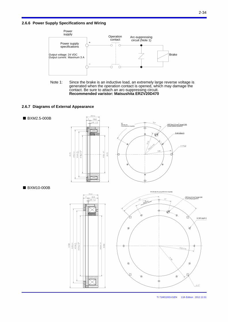
TI 71M01D03-01EN 11th Edition : 2012.12.01
2.6.6 Power Supply Specifications and Wiring
Note 1: Since the brake is an inductive load, an extremely large reverse voltage is generated when the operation contact is opened, which may damage the contact. Be sure to attach an arc-suppressing circuit.Recommended varistor: Matsushita ERZV20D470
2.6.7 Diagrams of External Appearance
Power supply specifications
Power supply
Operation contact
Arc-suppressing circuit (Note 1)
Brake
+
-
BXM2.5-000B
BXM10-000B
2-34
Output voltage: 24 VDCOutput current: Maximum 3 A
60 (Divide the circumference equally)
FEP line 0.5 mm2 length 300(Lead pullout position)
6-M4 depth 8
90 (Divide the circumference equally)
FEP line 0.5 mm2 length 300(Lead pullout position)
30
(Divide the
circumference equally)
12-M6 depth 6
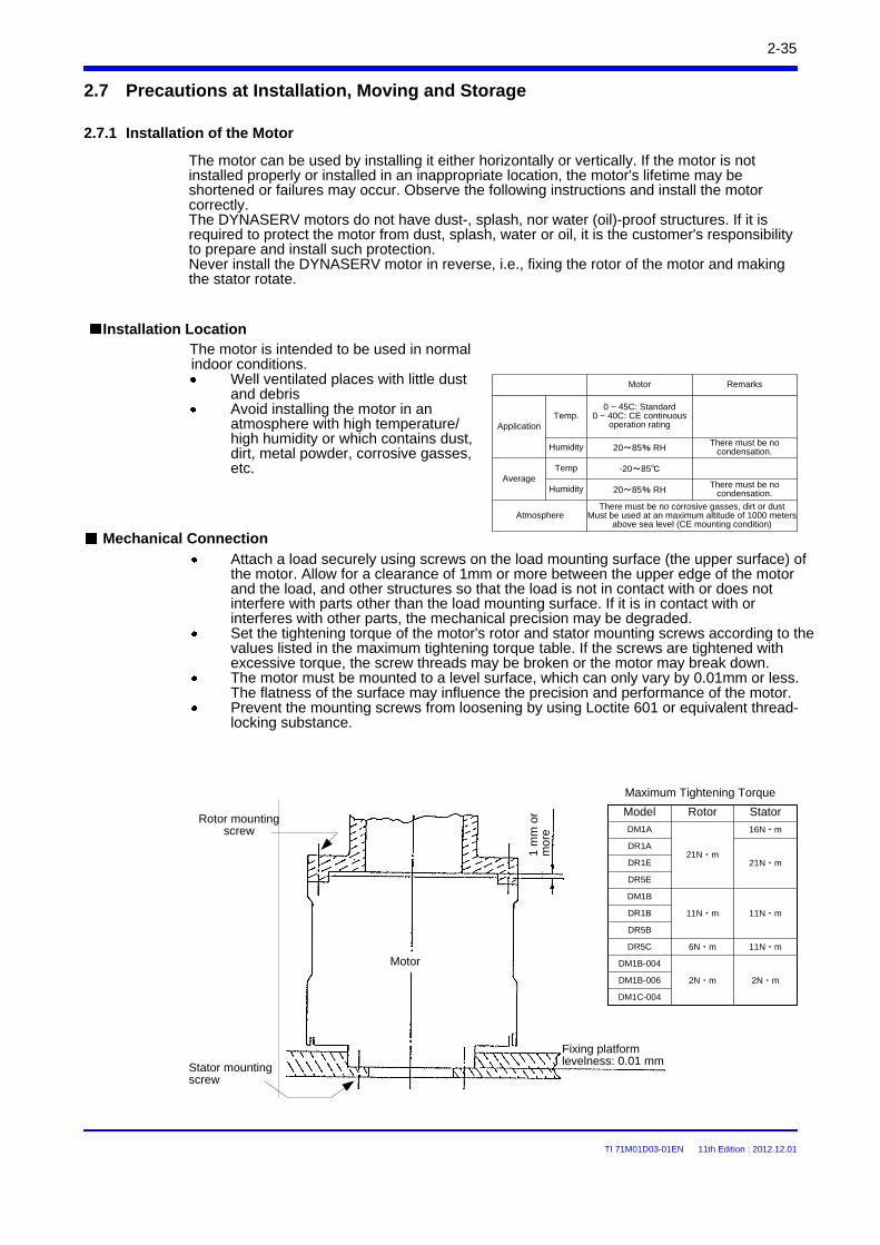
TI 71M01D03-01EN 11th Edition : 2012.12.01
2-35
2.7 Precautions at Installation, Moving and Storage
Attach a load securely using screws on the load mounting surface (the upper surface) of the motor. Allow for a clearance of 1mm or more between the upper edge of the motor and the load, and other structures so that the load is not in contact with or does not interfere with parts other than the load mounting surface. If it is in contact with or interferes with other parts, the mechanical precision may be degraded.Set the tightening torque of the motor's rotor and stator mounting screws according to the values listed in the maximum tightening torque table. If the screws are tightened with excessive torque, the screw threads may be broken or the motor may break down.The motor must be mounted to a level surface, which can only vary by 0.01mm or less. The flatness of the surface may influence the precision and performance of the motor.Prevent the mounting screws from loosening by using Loctite 601 or equivalent thread-locking substance.
Mechanical Connection
Installation Location
The motor can be used by installing it either horizontally or vertically. If the motor is not installed properly or installed in an inappropriate location, the motor's lifetime may be shortened or failures may occur. Observe the following instructions and install the motor correctly.The DYNASERV motors do not have dust-, splash, nor water (oil)-proof structures. If it is required to protect the motor from dust, splash, water or oil, it is the customer's responsibility to prepare and install such protection.Never install the DYNASERV motor in reverse, i.e., fixing the rotor of the motor and making the stator rotate.
2.7.1 Installation of the Motor
Motor
1 m
m o
r m
ore
Fixing platform levelness: 0.01 mm
Rotor mounting screw
Stator mounting screw
Maximum Tightening Torque
Model Rotor Stator
DM1A 16N・m
DR1A
DR1E
DR5E
DM1B
DR1B
DR5B
DR5C 6N・m
11N・m
DM1B-004
DM1B-006
DM1C-004
2N・m 2N・m
21N・m
11N・m
11N・m
21N・m
The motor is intended to be used in normal indoor conditions.
Well ventilated places with little dust and debrisAvoid installing the motor in an atmosphere with high temperature/high humidity or which contains dust, dirt, metal powder, corrosive gasses, etc.
Application
Motor
0 ~ 45C: Standard0 ~ 40C: CE continuous
operation rating
20~85% RH
There must be no corrosive gasses, dirt or dustMust be used at an maximum altitude of 1000 meters
above sea level (CE mounting condition)Atmosphere
Average
Temp.
Humidity
Temp
Humidity
-20~85
20~85% RH
Remarks
There must be no condensation.
There must be no condensation.
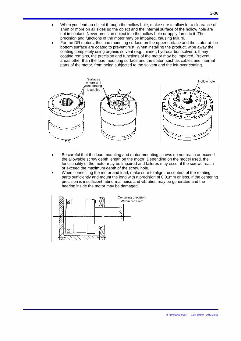
TI 71M01D03-01EN 11th Edition : 2012.12.01
2-36
When you lead an object through the hollow hole, make sure to allow for a clearance of 1mm or more on all sides so the object and the internal surface of the hollow hole are not in contact. Never press an object into the hollow hole or apply force to it. The precision and functions of the motor may be impaired, causing failure.For the DR motors, the load mounting surface on the upper surface and the stator at the bottom surface are coated to prevent rust. When installing the product, wipe away the coating completely using organic solvent (e.g. thinner, hydrocarbon solvent). If any coating remains, the precision and functions of the motor may be impaired. Prevent areas other than the load mounting surface and the stator, such as cables and internal parts of the motor, from being subjected to the solvent and the left-over coating.
Be careful that the load mounting and motor mounting screws do not reach or exceed the allowable screw depth length on the motor. Depending on the model used, the functionality of the motor may be impaired and failures may occur if the screws reach or exceed the maximum depth of the screw hole.When connecting the motor and load, make sure to align the centers of the rotating parts sufficiently and mount the load with a precision of 0.01mm or less. If the centering precision is insufficient, abnormal noise and vibration may be generated and the bearing inside the motor may be damaged.
Hollow holeSurfaces
where anti rust coating is applied
Centering precision: Within 0.01 mm
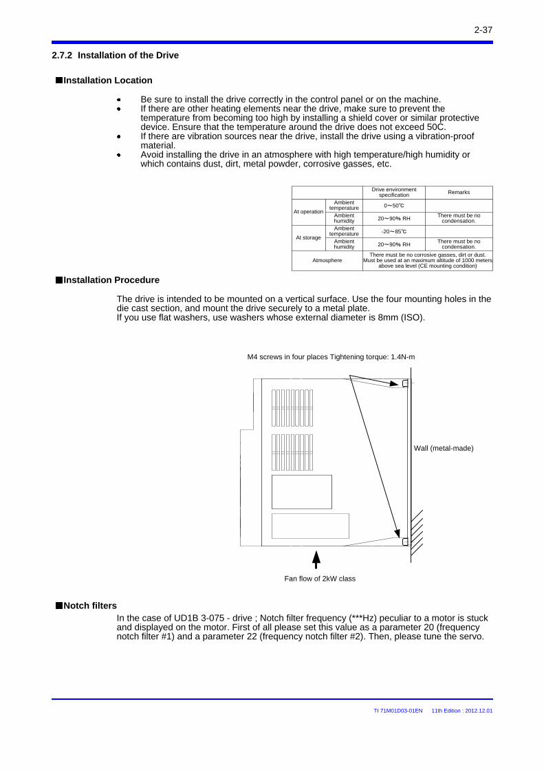
TI 71M01D03-01EN 11th Edition : 2012.12.01
2-37
2.7.2 Installation of the Drive
The drive is intended to be mounted on a vertical surface. Use the four mounting holes in the die cast section, and mount the drive securely to a metal plate.If you use flat washers, use washers whose external diameter is 8mm (ISO).
Installation Location
Be sure to install the drive correctly in the control panel or on the machine.If there are other heating elements near the drive, make sure to prevent the temperature from becoming too high by installing a shield cover or similar protective device. Ensure that the temperature around the drive does not exceed 50C.If there are vibration sources near the drive, install the drive using a vibration-proof material.Avoid installing the drive in an atmosphere with high temperature/high humidity or which contains dust, dirt, metal powder, corrosive gasses, etc.
Installation Procedure
Wall (metal-made)
Fan flow of 2kW class
M4 screws in four places Tightening torque: 1.4N-m
At operation
Atmosphere
At storage
Ambient temperature
There must be no corrosive gasses, dirt or dust.Must be used at an maximum altitude of 1000 meters
above sea level (CE mounting condition)
Remarks
There must be no condensation.
There must be no condensation.
Drive environment specification
0~50
20~90% RH
-20~85
20~90% RH
Ambient humidityAmbient
temperatureAmbient humidity
In the case of UD1B 3-075 - drive ; Notch filter frequency (***Hz) peculiar to a motor is stuck and displayed on the motor. First of all please set this value as a parameter 20 (frequency notch filter #1) and a parameter 22 (frequency notch filter #2). Then, please tune the servo.
Notch filters
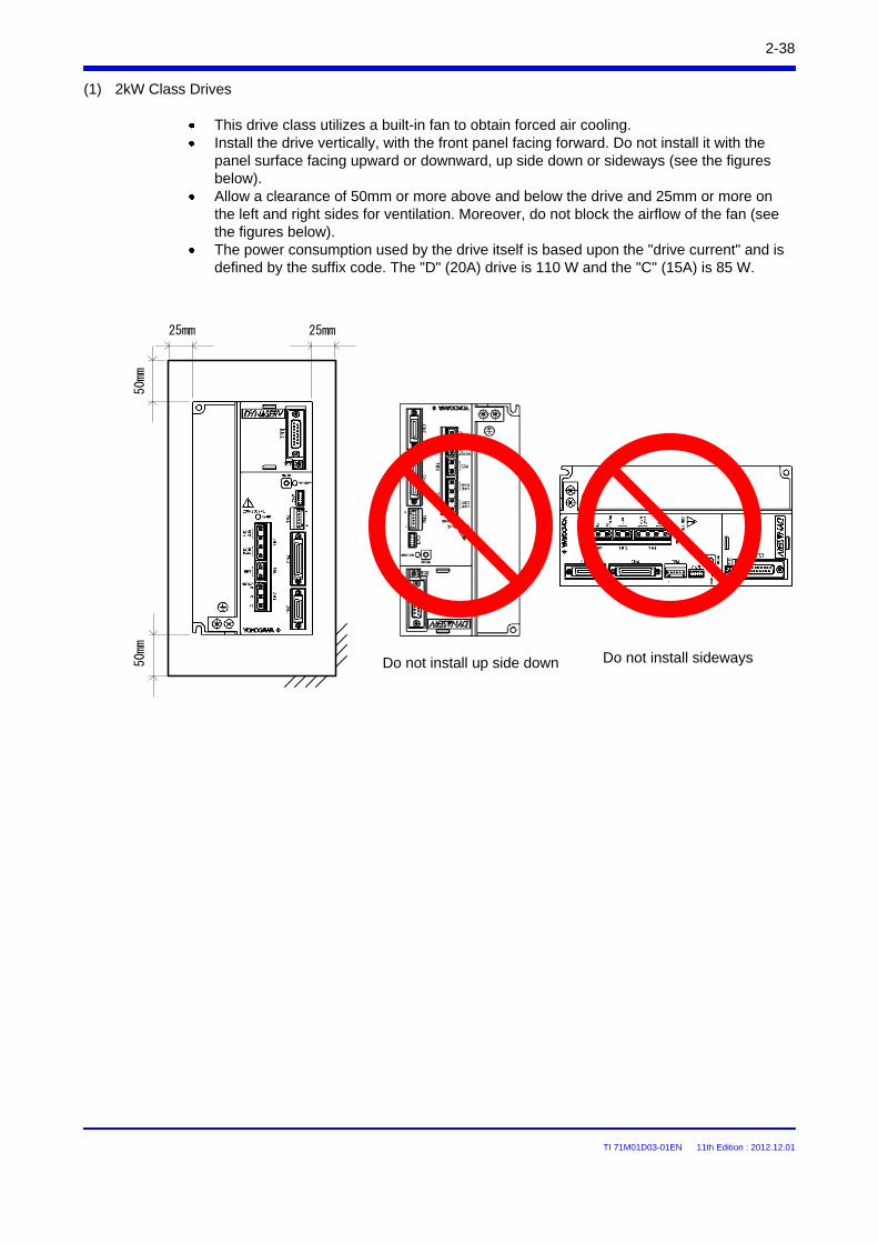
TI 71M01D03-01EN 11th Edition : 2012.12.01
2-38
(1) 2kW Class Drives
This drive class utilizes a built-in fan to obtain forced air cooling.Install the drive vertically, with the front panel facing forward. Do not install it with the panel surface facing upward or downward, up side down or sideways (see the figures below).Allow a clearance of 50mm or more above and below the drive and 25mm or more on the left and right sides for ventilation. Moreover, do not block the airflow of the fan (see the figures below).The power consumption used by the drive itself is based upon the "drive current" and is defined by the suffix code. The "D" (20A) drive is 110 W and the "C" (15A) is 85 W.
Do not install sidewaysDo not install up side down
25mm25mm
50mm
50mm
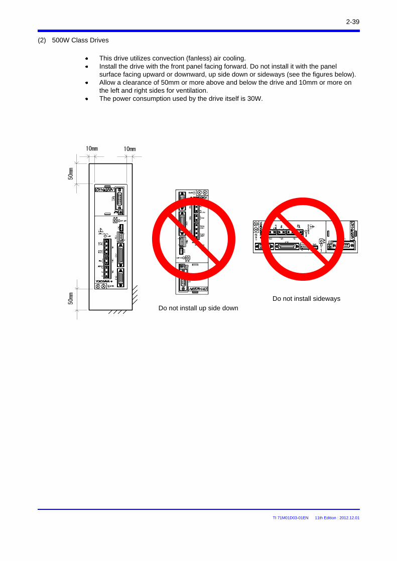
TI 71M01D03-01EN 11th Edition : 2012.12.01
2-39
(2) 500W Class Drives
Do not install sideways
Do not install up side down
This drive utilizes convection (fanless) air cooling.Install the drive with the front panel facing forward. Do not install it with the panel surface facing upward or downward, up side down or sideways (see the figures below).Allow a clearance of 50mm or more above and below the drive and 10mm or more on the left and right sides for ventilation.The power consumption used by the drive itself is 30W.
10mm10mm
50mm
50mm
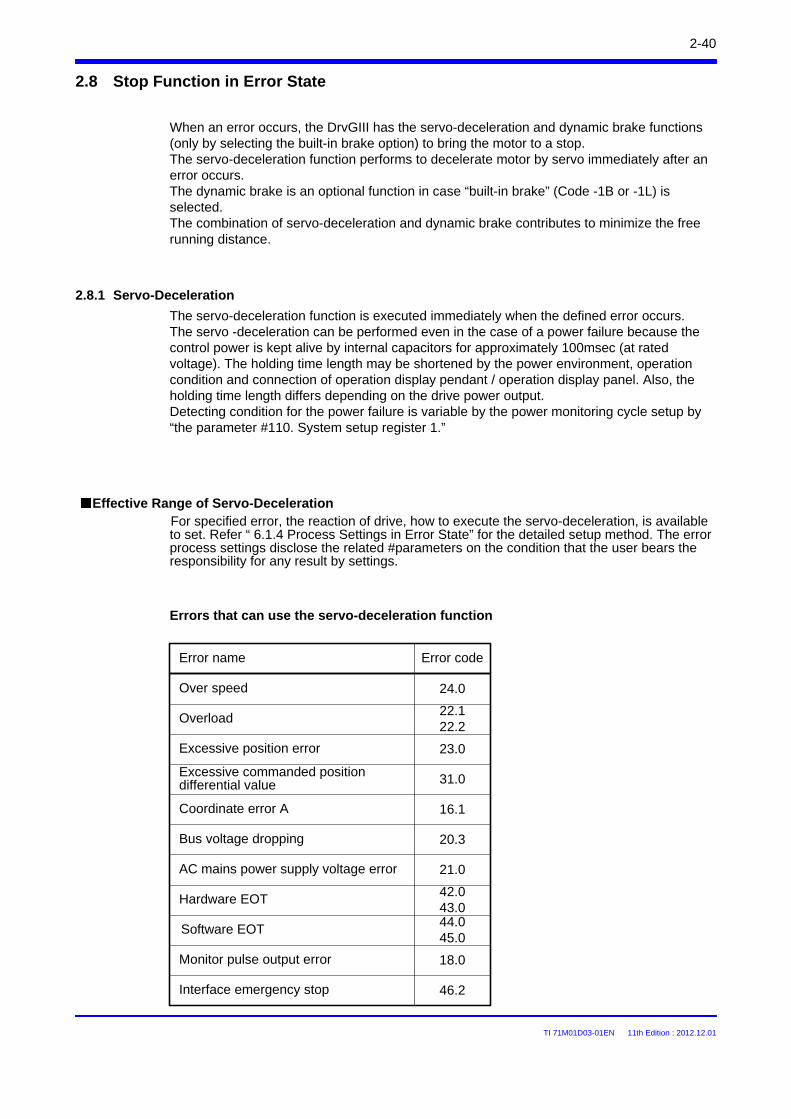
TI 71M01D03-01EN 11th Edition : 2012.12.01
2.8 Stop Function in Error State
2-40
When an error occurs, the DrvGIII has the servo-deceleration and dynamic brake functions (only by selecting the built-in brake option) to bring the motor to a stop.The servo-deceleration function performs to decelerate motor by servo immediately after an error occurs. The dynamic brake is an optional function in case “built-in brake” (Code -1B or -1L) is selected.The combination of servo-deceleration and dynamic brake contributes to minimize the free running distance.
2.8.1 Servo-Deceleration
Errors that can use the servo-deceleration function
Error name
Overload
Over speed
Excessive position error
Interface emergency stop
Software EOT
Excessive commanded position differential value
Coordinate error A
Bus voltage dropping
AC mains power supply voltage error
Hardware EOT
Monitor pulse output error
Error code
22.122.2
24.0
23.0
31.0
16.1
21.0
20.3
18.0
42.043.044.045.0
46.2
For specified error, the reaction of drive, how to execute the servo-deceleration, is available to set. Refer “ 6.1.4 Process Settings in Error State” for the detailed setup method. The error process settings disclose the related #parameters on the condition that the user bears the responsibility for any result by settings.
Effective Range of Servo-Deceleration
The servo-deceleration function is executed immediately when the defined error occurs. The servo -deceleration can be performed even in the case of a power failure because the control power is kept alive by internal capacitors for approximately 100msec (at rated voltage). The holding time length may be shortened by the power environment, operation condition and connection of operation display pendant / operation display panel. Also, the holding time length differs depending on the drive power output.Detecting condition for the power failure is variable by the power monitoring cycle setup by “the parameter #110. System setup register 1.”
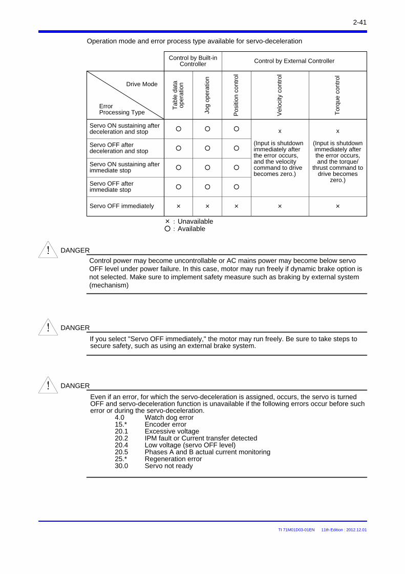
TI 71M01D03-01EN 11th Edition : 2012.12.01
Pos
ition
con
trol
Servo ON sustaining after deceleration and stop
Vel
ocity
con
trol
Tor
que
con
tro
l
Tab
le d
ata
op
erat
ion
Jog
ope
ratio
n
x
(Input is shutdown immediately after the error occurs, and the velocity command to drive becomes zero.)
Control by Built-in Controller Control by External Controller
Servo OFF after deceleration and stop
Servo ON sustaining after immediate stop
Servo OFF after immediate stop
Servo OFF immediately
ErrorProcessing Type
Drive Mode
×××
Operation mode and error process type available for servo-deceleration
×:Unavailable:Available
If you select "Servo OFF immediately," the motor may run freely. Be sure to take steps to secure safety, such as using an external brake system.
DANGER
Control power may become uncontrollable or AC mains power may become below servo OFF level under power failure. In this case, motor may run freely if dynamic brake option is not selected. Make sure to implement safety measure such as braking by external system (mechanism)
DANGER
x
(Input is shutdown immediately after the error occurs, and the torque/
thrust command to drive becomes
zero.)
× ×
2-41
Even if an error, for which the servo-deceleration is assigned, occurs, the servo is turned OFF and servo-deceleration function is unavailable if the following errors occur before such error or during the servo-deceleration.
4.0 Watch dog error15.* Encoder error20.1 Excessive voltage20.2 IPM fault or Current transfer detected20.4 Low voltage (servo OFF level)20.5 Phases A and B actual current monitoring25.* Regeneration error30.0 Servo not ready
DANGER
TI 71M01D03-01EN 11th Edition : 2012.12.01
The dynamic brake is an optional function is available only when "built-in brake" (code -1B or -1L) is selected.This is supplemental brake to minimize free-run distance by motor control torque generated by shorted motor winding when an error occurs and servo is turned OFF.
2.8.2 Dynamic Brake (with selection -1B or -1L)
CAUTION
The dynamic brake is in intended for use when servo is turned OFF by an error.Do not use the brake for frequent stop operation in servo-OFF or power-OFF during operation or usage to rotate the motor by an external force. Continuous activation of dynamic brake circuit may cause degradation of element in drive and unexpected defect or malfunction.Make sure to control the motor by normal control mode (torque, velocity or position command) in order to stop the motor.
Dynamic brake activates under the following conditions. Set System setup“ register 1 of parameter #110 to activate the brake when error occurs.1. Shutdown of AC mains or control power2. Bus voltage of drive drops down to below servo OFF level3. Servo is turned OFF if “Brake-ON during servo-OFF” option of system setup register 1 in
parameter #110 is set to “1: Enable).
Effective range of dynamic brake
CAUTION
When AC mains or control power is turned OFF, the dynamic brake is activated. When it is necessary to cancel the dynamic brake, make sure to set safe and appropriate external circuit so that the motor wiring is cutoff.
Braking force of dynamic brake differs depending on motor, load and operational conditions. Simulate under the worst conditions with the motor, and make sure to implement safety measure such as braking by external system (mechanism).
DANGER
2-42
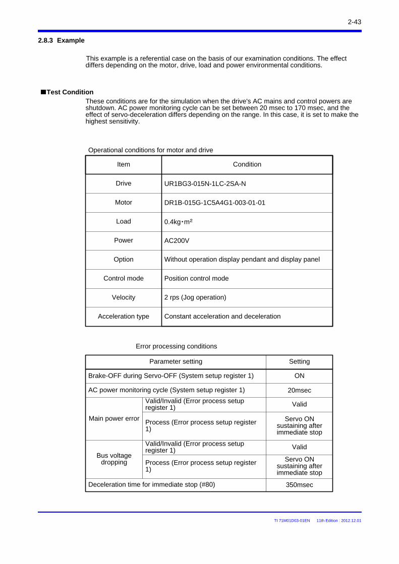
TI 71M01D03-01EN 11th Edition : 2012.12.01
Error processing conditions
Brake-OFF during Servo-OFF (System setup register 1)
Main power error
Valid/Invalid (Error process setup register 1)
Servo ON sustaining after immediate stop
Bus voltage dropping
Setting
ON
Valid
Parameter setting
Test Condition
AC power monitoring cycle (System setup register 1) 20msec
Motor
UR1BG3-015N-1LC-2SA-N
0.4kg・m2
DR1B-015G-1C5A4G1-003-01-01
Item Condition
Drive
Load
These conditions are for the simulation when the drive's AC mains and control powers are shutdown. AC power monitoring cycle can be set between 20 msec to 170 msec, and the effect of servo-deceleration differs depending on the range. In this case, it is set to make the highest sensitivity.
Process (Error process setup register 1)
Valid/Invalid (Error process setup register 1)
Servo ON sustaining after immediate stop
Valid
Process (Error process setup register 1)
350msecDeceleration time for immediate stop (#80)
Velocity 2 rps (Jog operation)
This example is a referential case on the basis of our examination conditions. The effect differs depending on the motor, drive, load and power environmental conditions.
Constant acceleration and deceleration
Without operation display pendant and display panelOption
Acceleration type
2.8.3 Example
AC200VPower
Operational conditions for motor and drive
Position control modeControl mode
2-43
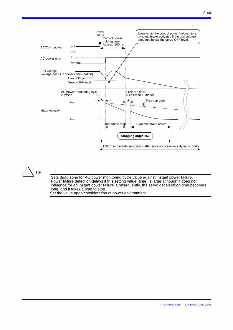
TI 71M01D03-01EN 11th Edition : 2012.12.01
Sets dead zone for AC power monitoring cycle value against instant power failure.Power failure detection delays if this setting value (time) is large although it does not influence for an instant power failure. Consequently, the servo deceleration time becomes long, and it takes a time to stop.Set the value upon consideration of power environment.
TIP
2-44
Motor velocity
Bus voltage(voltage post-AC power commutation)
Low voltage error
Free-run time(Less than 15msec)
Control power holding timeApprox. 100ms
Servo-OFF level
AC power monitoring cycle20msec
Immediate stop Dynamic brake active
Free-run time
Power failure
AC/Cont. power
OFF
ON
2rps
0rps
(1100°if immediate servo-OFF after error occurs unless dynamic brake)
Stopping angle 260
AC power errorNormal
Error
Even within the control power holding time, dynamic brake activates if the bus voltage becomes below the servo-OFF level.
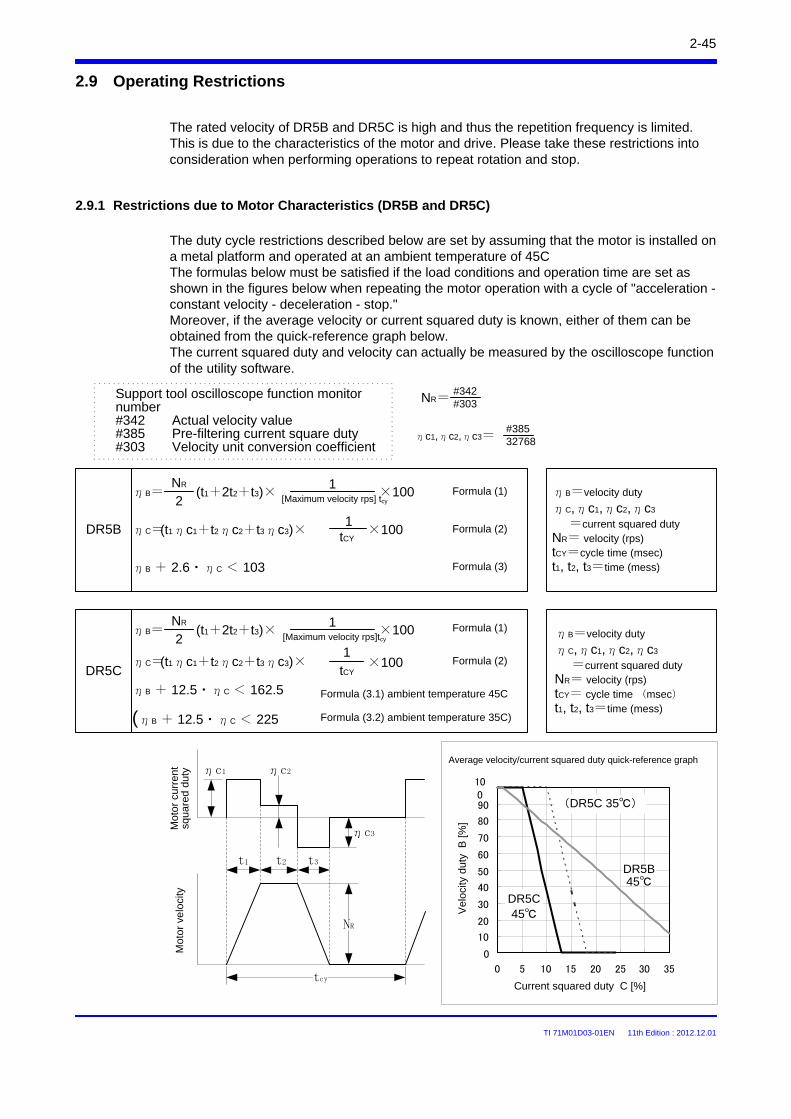
TI 71M01D03-01EN 11th Edition : 2012.12.01
2-45
2.9 Operating Restrictions
The rated velocity of DR5B and DR5C is high and thus the repetition frequency is limited. This is due to the characteristics of the motor and drive. Please take these restrictions into consideration when performing operations to repeat rotation and stop.
2.9.1 Restrictions due to Motor Characteristics (DR5B and DR5C)
The duty cycle restrictions described below are set by assuming that the motor is installed on a metal platform and operated at an ambient temperature of 45CThe formulas below must be satisfied if the load conditions and operation time are set as shown in the figures below when repeating the motor operation with a cycle of "acceleration -constant velocity - deceleration - stop." Moreover, if the average velocity or current squared duty is known, either of them can be obtained from the quick-reference graph below.The current squared duty and velocity can actually be measured by the oscilloscope function of the utility software.
Support tool oscilloscope function monitor number#342 Actual velocity value#385 Pre-filtering current square duty#303 Velocity unit conversion coefficient
ηB=velocity duty
ηC,ηc1,ηc2,ηc3
=current squared dutyNR= velocity (rps)tCY=cycle time (msec)t1, t2, t3=time (mess)
0
10
20
30
40
50
60
70
80
90
100
0 5 10 15 20 25 30 35
ηB=velocity duty
ηC,ηc1,ηc2,ηc3
=current squared dutyNR= velocity (rps)tCY= cycle time (msec)t1, t2, t3=time (mess)
DR5B
DR5C
DR5B45
(DR5C 35)
DR5C45
ηc1
ηc3
ηc2
t1 t2 t3
NR
tcy
ηC=(t1ηc1+t2ηc2+t3ηc3)× tCY
1×100 Formula (2)
ηB + 2.6・ηC < 103 Formula (3)
ηC=tCY
1×100 Formula (2)(t1ηc1+t2ηc2+t3ηc3)×
ηB + 12.5・ηC < 162.5 Formula (3.1) ambient temperature 45C
(ηB + 12.5・ηC < 225 Formula (3.2) ambient temperature 35C)
#342#303NR=
#38532768ηc1,ηc2,ηc3=
ηB=2
NR(t1+2t2+t3)×
[Maximum velocity rps] tcy
1×100 Formula (1)
ηB=2
NR(t1+2t2+t3)×
[Maximum velocity rps]tcy
1×100 Formula (1)
Average velocity/current squared duty quick-reference graph
Vel
ocity
dut
y B
[%]
Current squared duty C [%]
Mot
or
curr
ent
squa
red
duty
Mot
or v
eloc
ity
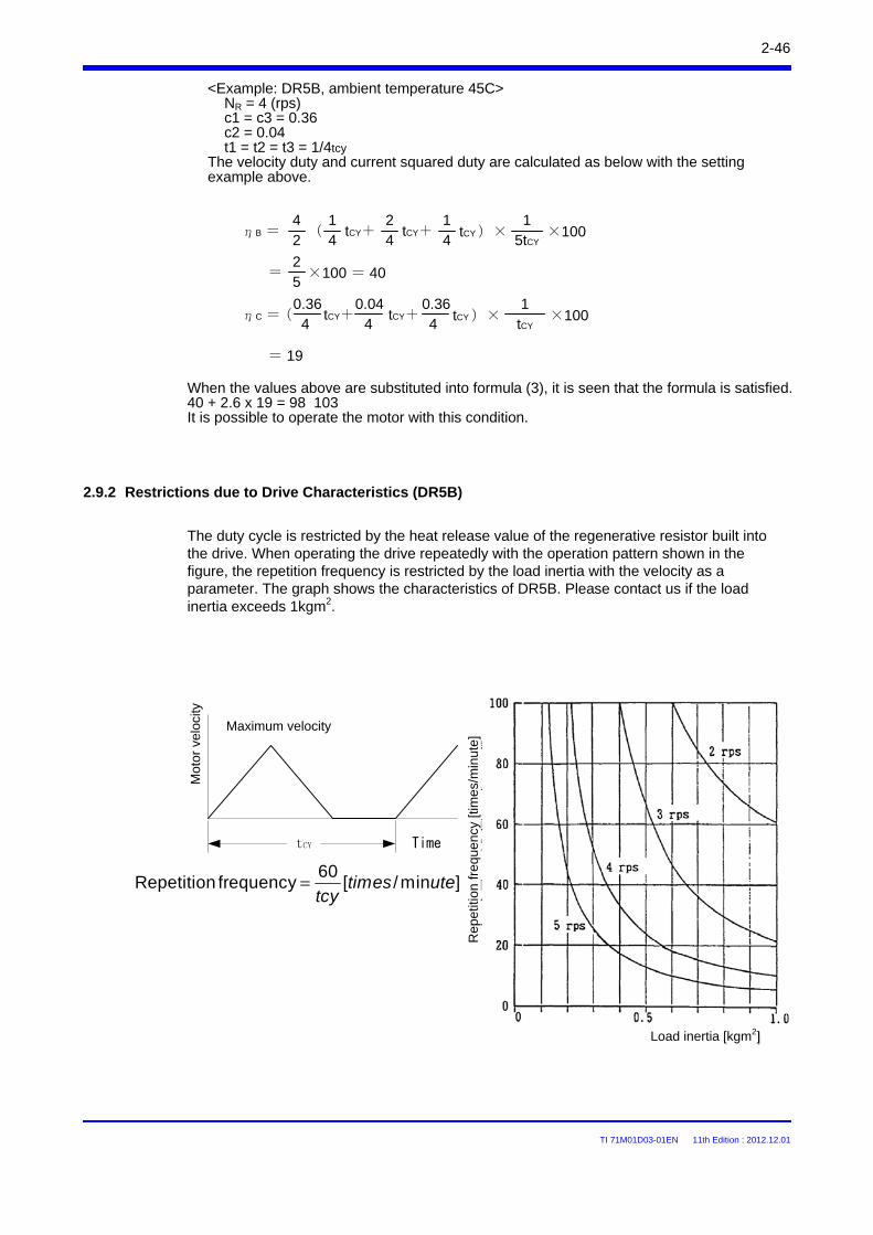
TI 71M01D03-01EN 11th Edition : 2012.12.01
2-46
2.9.2 Restrictions due to Drive Characteristics (DR5B)
The duty cycle is restricted by the heat release value of the regenerative resistor built into the drive. When operating the drive repeatedly with the operation pattern shown in the figure, the repetition frequency is restricted by the load inertia with the velocity as a parameter. The graph shows the characteristics of DR5B. Please contact us if the load inertia exceeds 1kgm2.
<Example: DR5B, ambient temperature 45C>NR = 4 (rps)c1 = c3 = 0.36c2 = 0.04t1 = t2 = t3 = 1/4tcy
The velocity duty and current squared duty are calculated as below with the setting example above.
When the values above are substituted into formula (3), it is seen that the formula is satisfied.40 + 2.6 x 19 = 98 103It is possible to operate the motor with this condition.
tCY Time
Maximum velocity
Mot
or v
eloc
ity
ηB =24
(41
tCY+42
tCY+41
tCY )×5tCY
1×100
=52
×100 = 40
ηC =(4
0.36tCY+
40.04
tCY+4
0.36tCY )×
tCY
1×100
= 19
]min/[60
frequency Repetition utetimestcy
=
Rep
etiti
on fr
eque
ncy
[tim
es/m
inut
e]
Load inertia [kgm2]

TI 71M01D03-01EN 11th Edition : 2012.12.01
2.9.3 Restrictions on the Number of EEPROM Registrations
The user setting data (parameters, table data and I/O data) is stored in the EEPROM built into the drive. There is a restriction on the number of times to overwrite the data due to the EEPROM characteristics. The number of allowable times to overwrite each area (parameters, table data and I/O data) is approximately 1 million times, respectively.
2-47
TI 71M01D03-01EN 11th Edition : 2012.12.01
2.10 Conformed Standards
2-48
Motor
Low Voltage Directive (declaration) EN50178EMC directive (declaration) EN55011 class A group 1, EN61800-3UL508C
Drive
In order to conform to the EMC directive, it is necessary to obtain certification for the entire equipment, including Yokogawa Electric's motor and drive, and control devices and electric components used in the customers' equipment.The conformity of equipment to the EMC directive varies depending on the structure of control devices and components used in equipment, and wiring. It is the customers' responsibility to check and certify equipment's conformity.
Low Voltage Directive (declaration) IEC34-1EMC directive (declaration) EN55011 class A group 1, EN61800-3
The drive is certified to conform to the following UL standard:Conformance with standard UL508C (File No. E238911)
[Conformation to UL standard]
[UL Standard Certification Conditions and Safety Precautions]
(i) Use 60/75 degrees Celsius CU wire only. (ii) Open Type Equipment. Be sure to install the drive in the control panel before using it.
It cannot be used if hung on a wall.(iii) Suitable for use on a circuit capable of delivering not more than 5000 Arms
symmetrical amperes, 240V maximum.(iv) Distribution fuse size marking is included in the manual to indicate that the unit shall
be connected with a Listed Class RK1 Fuse with the current ratings as shown in the table below:
Model No. Class RK1 FuseAll 500 W models 5 [A]All 2kW models 15 [A]
(v) Maximum surrounding air temperature 50 degrees Celsius.(vi) CAUTION - Risk of Electric Shock - Capacitor discharge time is at least 7min.(vii) CAUTION - Risk of Electric Shock - More than one disconnect switch may be required
to deenergize the equipment before servicing.(viii) Solid state motor overload protection is provided in each model.(ix) Install device in pollution degree 2 environment.(x) WARNING - Hot Surface - Risk of Burn.(xi) Drive has no provision for motor over temperature protection.
Motor over temperature protection is required at end application.
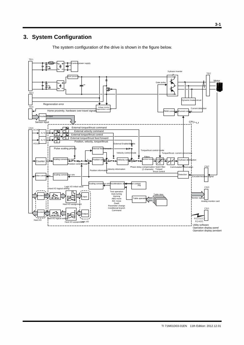
3-1
TI 71M01D03-01EN 11th Edition: 2012.12.01
3. System Configuration
The system configuration of the drive is shown in the figure below.
A/D
A/D
タ TB2
CN2
+-
+++-
+
ACMD
ASUB
+
+
TB1
TB3
TB4
CN4
CPU
CN1
RS232C/RS485
CN3
CPU
Home proximity, hardware over-travel signals
Phase delay compensation Notch filter(2 channels) Torque/
thrust control
Analog monitor card
Insulated input
Hard I/OHard I/O logical setting
Logic I/O
Counter3-phase distribution
Current detection
Machine resonance compensation
Filters
Position control
Commutation informationVelocity information
Position information
Gate pulse
Torque/thrust- current conversion
Acceleration/ deceleration control
External torque/thrust feed forward
External torque/thrust control
External velocity command
External torque/thrust command
Table data
Test operationAuto-tuning
Homing ABS move INC move
Dwell Parameter changeConditional branch
Command
Position control mode
Regeneration error
Sensor input
Encoder/resolver signal
Dynamic brake circuit
Current control
Monitor signal
Utility software Operation display panel Operation display pendant
Hard I/O assignment
Hard I/O assignment
Voltage monitor Regeneration control
PWM conversion
DetectionPulse conversion
Internal feed forward
Rush prevention
Insulated output
Logic I/O initial value
Pulse scaling priority
Scaling conversion n/m
Insulated input
Control power supply
Scaling conversion n/m
Motor
Hard I/O logical setting
Scaling conversion m/n
Velocity control mode
Position, velocity, torque/thrustExternal Enable/disable
Torque/trust control mode
Velocity control
Output
Table operation
Jog
Input
3-phase inverter

Blank Page
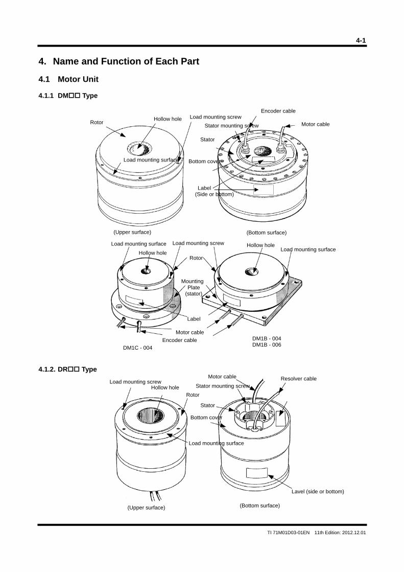
4-1
TI 71M01D03-01EN 11th Edition: 2012.12.01
4. Name and Function of Each Part 4.1 Motor Unit 4.1.1 DM Type 4.1.2. DR Type
Mounting Plate
(stator)
Label
(Upper surface) (Bottom surface)
Load mounting surface
Hollow hole
Load mounting screw
Rotor
Motor cable
Encoder cable
DM1C - 004
DM1B - 004 DM1B - 006
Load mounting surfaceHollow hole
RotorHollow hole Load mounting screw
Stator mounting screw
Stator
Encoder cable
Motor cable
Bottom cover
Label (Side or bottom)
Load mounting surface
Load mounting screw Hollow hole
Rotor
Resolver cable Stator mounting screw
Stator
Motor cable
Lavel (side or bottom)
(Upper surface) (Bottom surface)
Bottom cover
Load mounting surface
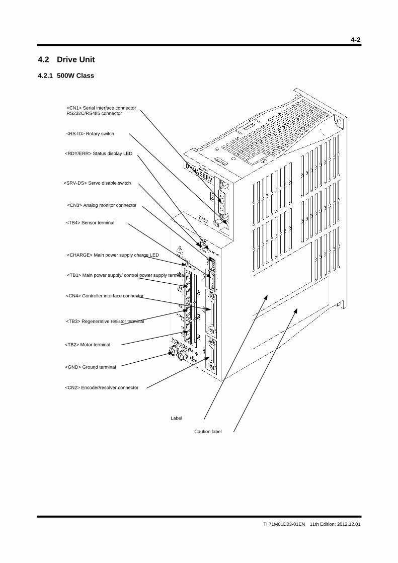
4-2
TI 71M01D03-01EN 11th Edition: 2012.12.01
4.2 Drive Unit 4.2.1 500W Class
<CN1> Serial interface connectorRS232C/RS485 connector
<RS-ID> Rotary switch
<SRV-DS> Servo disable switch
<CN3> Analog monitor connector
<TB4> Sensor terminal
<TB1> Main power supply/ control power supply terminal
<CN4> Controller interface connector
<TB3> Regenerative resistor terminal
<TB2> Motor terminal
<CN2> Encoder/resolver connector
<GND> Ground terminal
<RDY/ERR> Status display LED
<CHARGE> Main power supply charge LED
Label
Caution label
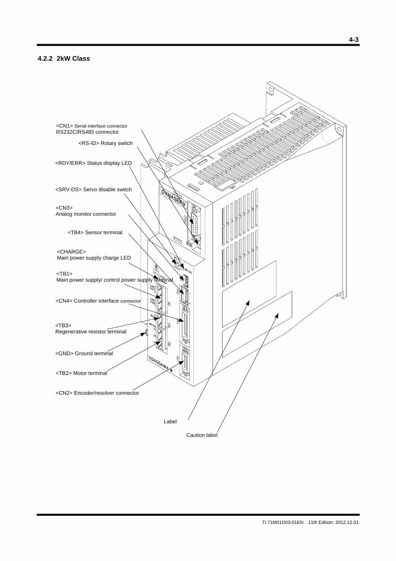
4-3
TI 71M01D03-01EN 11th Edition: 2012.12.01
4.2.2 2kW Class
<CN1> Serial interface connectorRS232C/RS485 connector
<RS-ID> Rotary switch
<SRV-DS> Servo disable switch
<CN3> Analog monitor connector
<TB4> Sensor terminal
<TB1> Main power supply/ control power supply terminal
<CN4> Controller interface connector
<TB3> Regenerative resistor terminal
<TB2> Motor terminal
<CN2> Encoder/resolver connector
<GND> Ground terminal
<RDY/ERR> Status display LED
<CHARGE> Main power supply charge LED
Label
Caution label
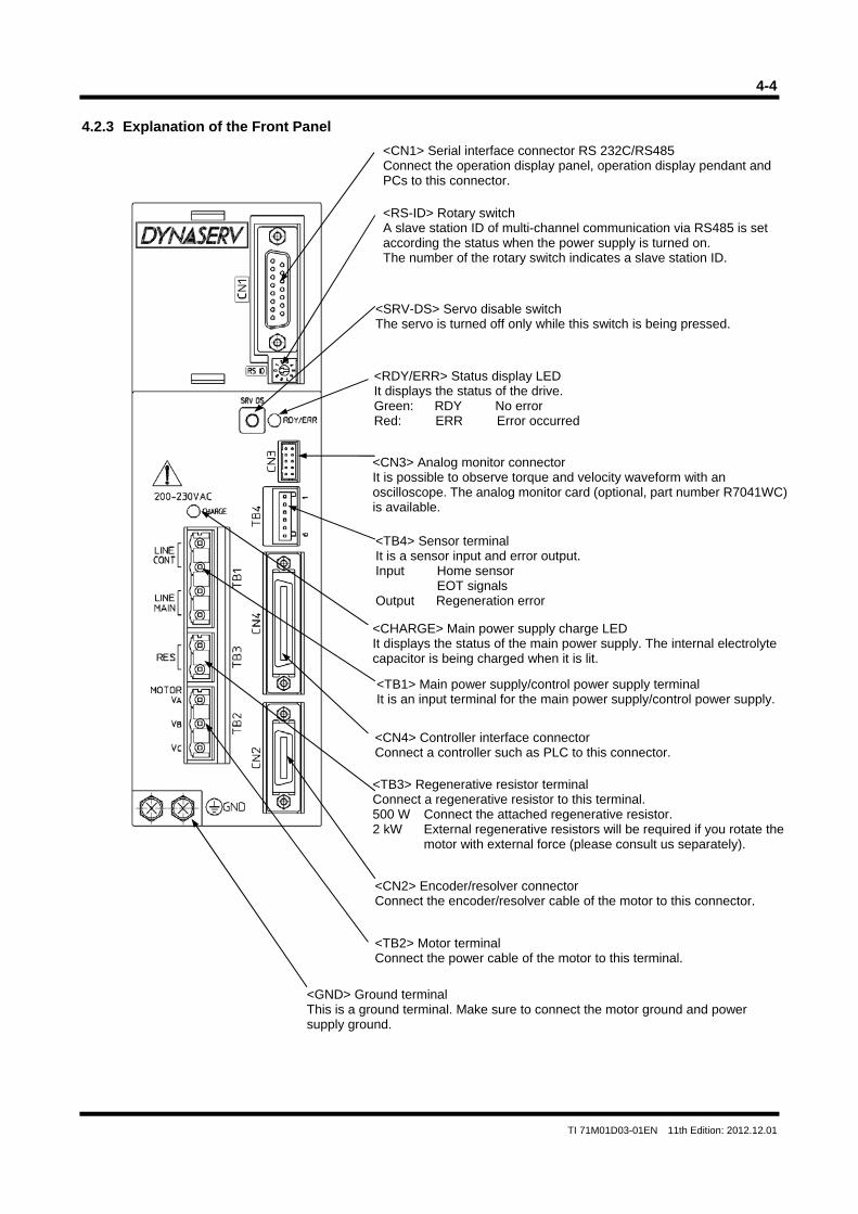
4-4
TI 71M01D03-01EN 11th Edition: 2012.12.01
4.2.3 Explanation of the Front Panel
<CN4> Controller interface connector Connect a controller such as PLC to this connector.
<TB2> Motor terminal Connect the power cable of the motor to this terminal.
<CN2> Encoder/resolver connector Connect the encoder/resolver cable of the motor to this connector.
<CHARGE> Main power supply charge LED It displays the status of the main power supply. The internal electrolyte capacitor is being charged when it is lit.
<CN1> Serial interface connector RS 232C/RS485 Connect the operation display panel, operation display pendant and PCs to this connector.
<RS-ID> Rotary switch A slave station ID of multi-channel communication via RS485 is set according the status when the power supply is turned on. The number of the rotary switch indicates a slave station ID.
<SRV-DS> Servo disable switch The servo is turned off only while this switch is being pressed.
<RDY/ERR> Status display LEDIt displays the status of the drive. Green: RDY No error Red: ERR Error occurred
<CN3> Analog monitor connector It is possible to observe torque and velocity waveform with an oscilloscope. The analog monitor card (optional, part number R7041WC)is available.
<TB4> Sensor terminal It is a sensor input and error output. Input Home sensor
EOT signals Output Regeneration error
<TB3> Regenerative resistor terminal Connect a regenerative resistor to this terminal. 500 W Connect the attached regenerative resistor. 2 kW External regenerative resistors will be required if you rotate the
motor with external force (please consult us separately).
<TB1> Main power supply/control power supply terminal It is an input terminal for the main power supply/control power supply.
<GND> Ground terminal This is a ground terminal. Make sure to connect the motor ground and power supply ground.
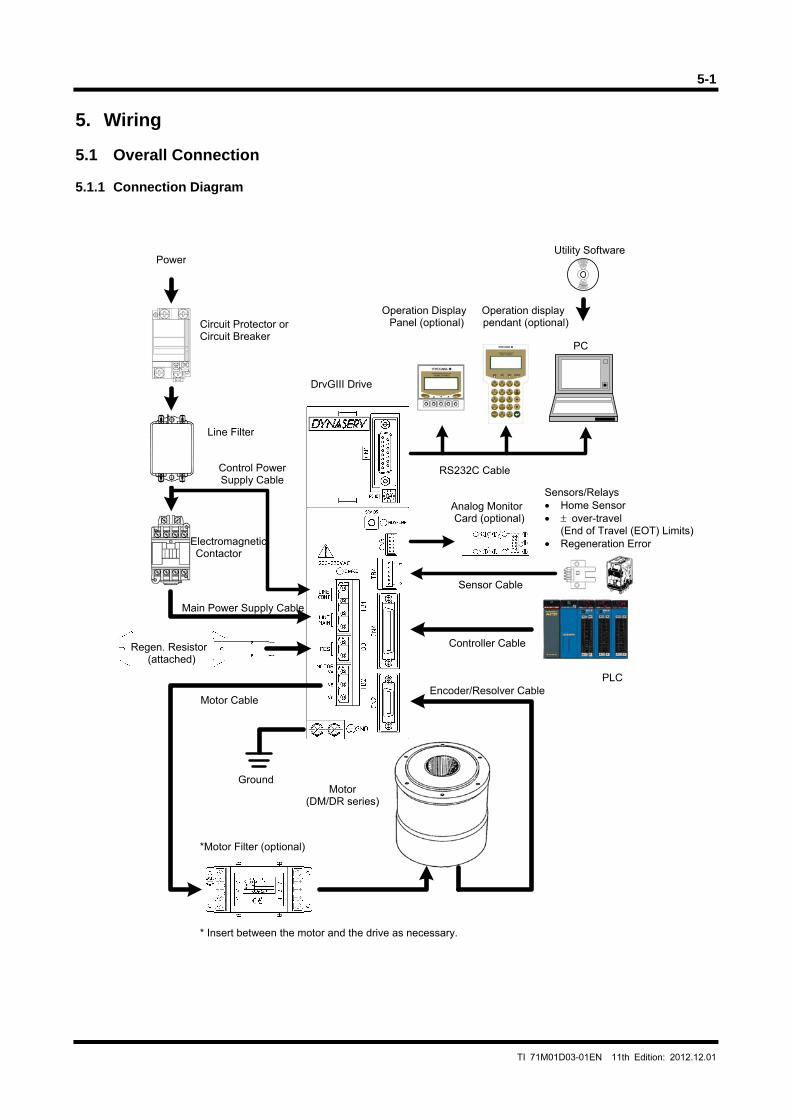
5-1
TI 71M01D03-01EN 11th Edition: 2012.12.01
5. Wiring 5.1 Overall Connection 5.1.1 Connection Diagram
Utility Software
Operation Display Panel (optional)
Operation display pendant (optional)
Analog Monitor Card (optional)
PLC
Sensors/Relays • Home Sensor • ± over-travel
(End of Travel (EOT) Limits)• Regeneration Error
Regen. Resistor (attached)
*Motor Filter (optional)
Circuit Protector or Circuit Breaker
Electromagnetic Contactor
PC
Motor (DM/DR series)
Power
DrvGIII Drive
Encoder/Resolver CableMotor Cable
Controller Cable
RS232C Cable
Line Filter
Main Power Supply Cable
Control PowerSupply Cable
Ground
Sensor Cable
* Insert between the motor and the drive as necessary.
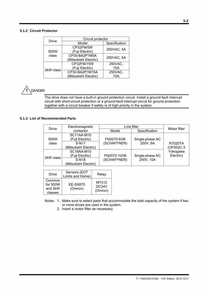
5-2
TI 71M01D03-01EN 11th Edition: 2012.12.01
5.1.2 Circuit Protector
Drive Circuit protector
Model Specification
500W class
CP32FM/5W (Fuji Electric)
250VAC, 5A
CP30-BA2P1M5A (Mitsubishi Electric)
250VAC, 5A
2kW class
CP32FM/15W (Fuji Electric)
250VAC, 15A
CP30-BA2P1M15A (Mitsubishi Electric)
250VAC, 15A
The drive does not have a built-in ground protection circuit. Install a ground-fault interrupt circuit with short-circuit protection or a ground-fault interrupt circuit for ground protection together with a circuit breaker if safety is of high priority in the system.
5.1.3 List of Recommended Parts
Drive Electromagnetic
contactor Line filter
Motor filter Model Specification
500W class
SC11AA-M10 (Fuji Electric) FN2070-6/06
(SCHAFFNER) Single-phase AC
250V, 6A R7020TA (OF002C-3 Yokogawa Electric)
S-N11 (Mitsubishi Electric)
2kW class
SC18AA-M10 (Fuji Electric) FN2070-10/06
(SCHAFFNER) Single-phase AC
250V, 10A S-N18 (Mitsubishi Electric)
Drive Sensors (EOT
Limits and Home)Relay
Common for 500W and 2kW classes
EE-SX670 (Omron)
MY2-D DC24V (Omron)
Notes: 1. Make sure to select parts that accommodate the total capacity of the system if two
or more drives are used in the system. 2. Insert a motor filter as necessary.
! DANGER
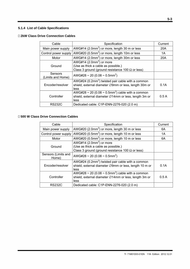
5-3
TI 71M01D03-01EN 11th Edition: 2012.12.01
5.1.4 List of Cable Specifications 2kW Class Drive Connection Cables
Cable Specification Current
Main power supply AWG#14 (2.0mm2) or more, length 30 m or less 20A
Control power supply AWG#20 (0.5mm2) or more, length 10m or less 1A
Motor AWG#14 (2.0mm2) or more, length 30m or less 20A
Ground AWG#14 (2.0mm2) or more (Use as thick a cable as possible.) Class 3 ground (ground resistance 100 Ω or less)
Sensors (Limits and Home)
AWG#28 ~ 20 (0.08 ~ 0.5mm2)
Encoder/resolver AWG#24 (0.2mm2) twisted pair cable with a common shield, external diameter ∅9mm or less, length 30m or less
0.1A
Controller AWG#28 ~ 20 (0.08 ~ 0.5mm2) cable with a common shield, external diameter ∅14mm or less, length 3m or less
0.5 A
RS232C Dedicated cable: C1P-ENN-2276-020 (2.0 m) 500 W Class Drive Connection Cables
Cable Specification Current
Main power supply AWG#20 (2.0mm2) or more, length 30 m or less 6A
Control power supply AWG#20 (0.5mm2) or more, length 10 m or less 1A
Motor AWG#20 (0.5mm2) or more, length 10 m or less 6A
Ground AWG#14 (2.0mm2) or more (Use as thick a cable as possible.) Class 3 ground (ground resistance 100 Ω or less)
Sensors (Limits and Home)
AWG#28 ~ 20 (0.08 ~ 0.5mm2)
Encoder/resolver AWG#24 (0.2mm2) twisted pair cable with a common shield, external diameter ∅9mm or less, length 10 m or less
0.1A
Controller AWG#28 ~ 20 (0.08 ~ 0.5mm2) cable with a common shield, external diameter ∅14mm or less, length 3m or less
0.5 A
RS232C Dedicated cable: C1P-ENN-2276-020 (2.0 m)
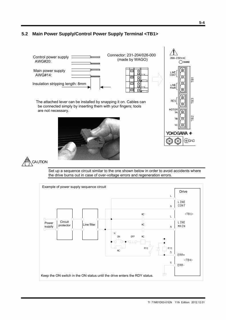
5-4
TI 71M01D03-01EN 11th Edition: 2012.12.01
RY1
ON OFF
MC
MC
MC
MCRY1
LINECONT
LINEMAIN
<TB1>
<TB4>ERR+
ERR-
※
L
L
N
N
5
6
5.2 Main Power Supply/Control Power Supply Terminal <TB1>
Set up a sequence circuit similar to the one shown below in order to avoid accidents where the drive burns out in case of over-voltage errors and regeneration errors.
CAUTION
Control power supply AWG#20:
Main power supply AWG#14:
Insulation stripping length: 8mm
The attached lever can be installed by snapping it on. Cables can be connected simply by inserting them with your fingers; tools are not necessary.
Connector: 231-204/026-000 (made by WAGO)
Line filterCircuit
protector Power supply
Drive
Keep the ON switch in the ON status until the drive enters the RDY status.
Example of power supply sequence circuit
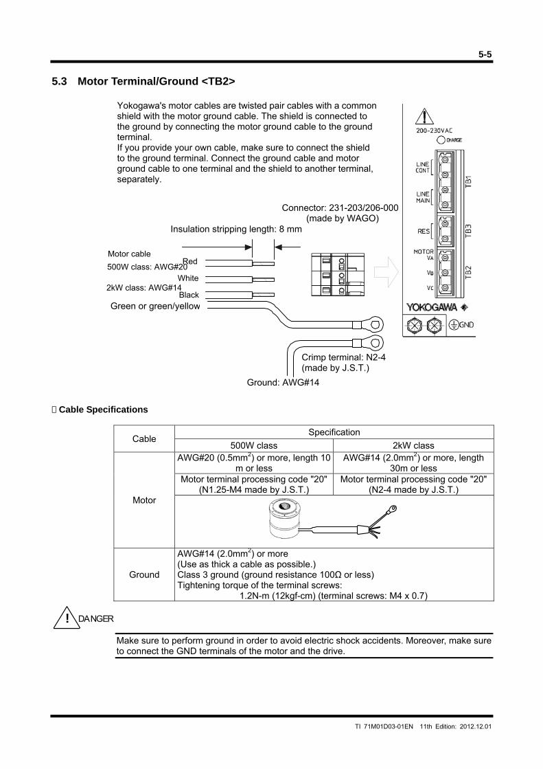
5-5
TI 71M01D03-01EN 11th Edition: 2012.12.01
5.3 Motor Terminal/Ground <TB2>
Cable Specifications
Cable Specification
500W class 2kW class
Motor
AWG#20 (0.5mm2) or more, length 10 m or less
AWG#14 (2.0mm2) or more, length 30m or less
Motor terminal processing code "20" (N1.25-M4 made by J.S.T.)
Motor terminal processing code "20" (N2-4 made by J.S.T.)
Ground
AWG#14 (2.0mm2) or more (Use as thick a cable as possible.) Class 3 ground (ground resistance 100Ω or less) Tightening torque of the terminal screws:
1.2N-m (12kgf-cm) (terminal screws: M4 x 0.7)
Make sure to perform ground in order to avoid electric shock accidents. Moreover, make sure to connect the GND terminals of the motor and the drive.
! DANGER
Yokogawa's motor cables are twisted pair cables with a commonshield with the motor ground cable. The shield is connected to the ground by connecting the motor ground cable to the ground terminal. If you provide your own cable, make sure to connect the shield to the ground terminal. Connect the ground cable and motor ground cable to one terminal and the shield to another terminal, separately.
500W class: AWG#20
2kW class: AWG#14
Insulation stripping length: 8 mm
Connector: 231-203/206-000 (made by WAGO)
Red
White
BlackGreen or green/yellow
Ground: AWG#14
Motor cable
Crimp terminal: N2-4(made by J.S.T.)
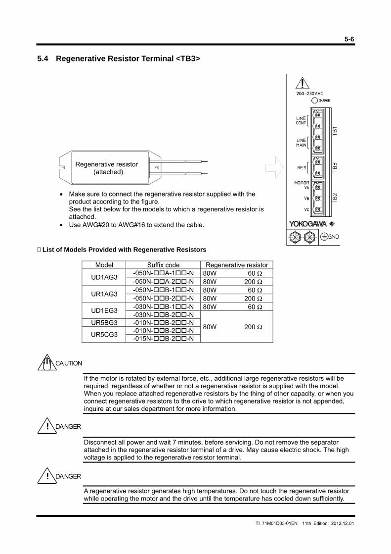
5-6
TI 71M01D03-01EN 11th Edition: 2012.12.01
5.4 Regenerative Resistor Terminal <TB3> List of Models Provided with Regenerative Resistors
Model Suffix code Regenerative resistor
UD1AG3 -050N-A-1-N 80W 60 Ω -050N-A-2-N 80W 200 Ω
UR1AG3 -050N-B-1-N 80W 60 Ω -050N-B-2-N 80W 200 Ω
UD1EG3 -030N-B-1-N 80W 60 Ω -030N-B-2-N
80W 200 Ω UR5BG3 -010N-B-2-N
UR5CG3 -010N-B-2-N -015N-B-2-N
If the motor is rotated by external force, etc., additional large regenerative resistors will be required, regardless of whether or not a regenerative resistor is supplied with the model. When you replace attached regenerative resistors by the thing of other capacity, or when you connect regenerative resistors to the drive to which regenerative resistor is not appended, inquire at our sales department for more information.
Disconnect all power and wait 7 minutes, before servicing. Do not remove the separator attached in the regenerative resistor terminal of a drive. May cause electric shock. The high voltage is applied to the regenerative resistor terminal.
A regenerative resistor generates high temperatures. Do not touch the regenerative resistor while operating the motor and the drive until the temperature has cooled down sufficiently.
CAUTION
! DANGER
• Make sure to connect the regenerative resistor supplied with the product according to the figure. See the list below for the models to which a regenerative resistor is attached.
• Use AWG#20 to AWG#16 to extend the cable.
Regenerative resistor (attached)
! DANGER
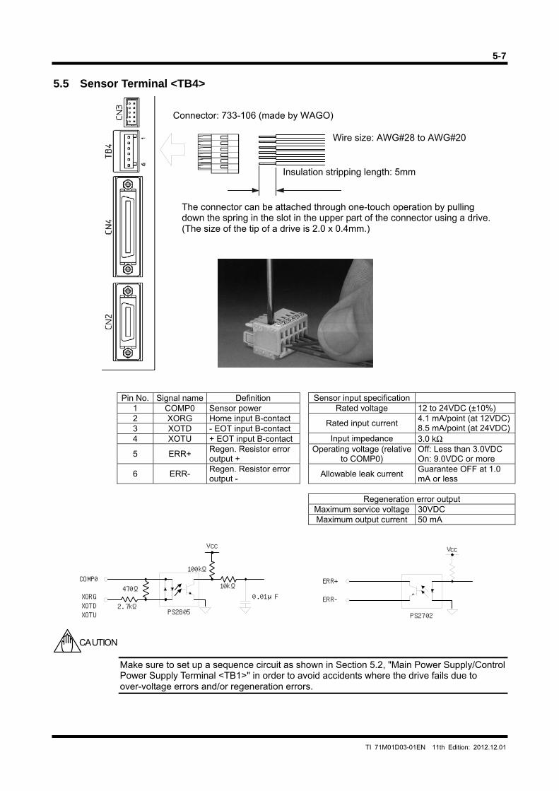
5-7
TI 71M01D03-01EN 11th Edition: 2012.12.01
470Ω
2.7kΩ
COMP0
XORGXOTDXOTU
100kΩ
10kΩ0.01μF
Vcc
PS2805 PS2702
ERR+
Vcc
ERR-
5.5 Sensor Terminal <TB4>
Pin No. Signal name Definition
1 COMP0 Sensor power 2 XORG Home input B-contact 3 XOTD - EOT input B-contact 4 XOTU + EOT input B-contact
5 ERR+ Regen. Resistor error output +
6 ERR- Regen. Resistor error output -
Make sure to set up a sequence circuit as shown in Section 5.2, "Main Power Supply/Control Power Supply Terminal <TB1>" in order to avoid accidents where the drive fails due to over-voltage errors and/or regeneration errors.
CAUTION
Sensor input specification Rated voltage 12 to 24VDC (±10%)
Rated input current 4.1 mA/point (at 12VDC)8.5 mA/point (at 24VDC)
Input impedance 3.0 kΩ Operating voltage (relative
to COMP0) Off: Less than 3.0VDC On: 9.0VDC or more
Allowable leak current Guarantee OFF at 1.0 mA or less
Regeneration error output
Maximum service voltage 30VDC Maximum output current 50 mA
Connector: 733-106 (made by WAGO)
Insulation stripping length: 5mm
The connector can be attached through one-touch operation by pulling down the spring in the slot in the upper part of the connector using a drive. (The size of the tip of a drive is 2.0 x 0.4mm.)
Wire size: AWG#28 to AWG#20
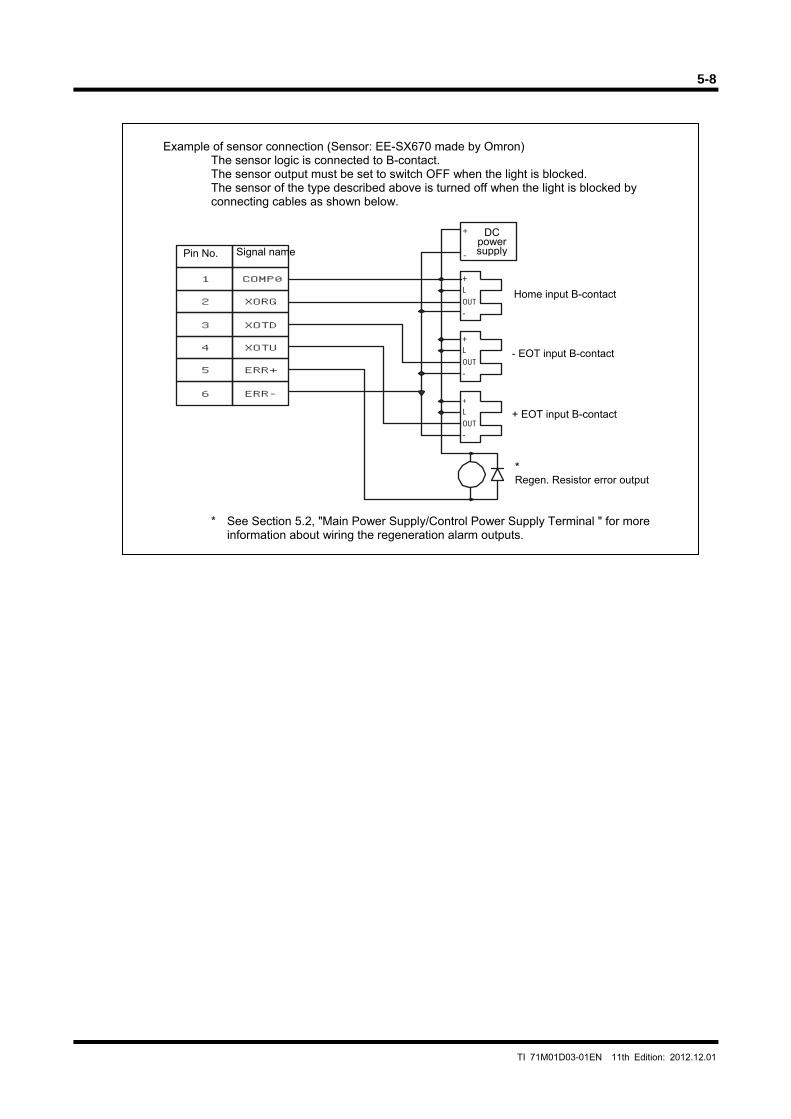
5-8
TI 71M01D03-01EN 11th Edition: 2012.12.01
+L
OUT
-
+L
OUT
-
+L
OUT
-
+
-
1
2
COMP0
3
4
XORG
XOTD
XOTU
5
6
ERR+
ERR-
Example of sensor connection (Sensor: EE-SX670 made by Omron) The sensor logic is connected to B-contact. The sensor output must be set to switch OFF when the light is blocked. The sensor of the type described above is turned off when the light is blocked by connecting cables as shown below.
* See Section 5.2, "Main Power Supply/Control Power Supply Terminal " for more information about wiring the regeneration alarm outputs.
DC power supplyPin No. Signal name
Home input B-contact
- EOT input B-contact
+ EOT input B-contact
* Regen. Resistor error output
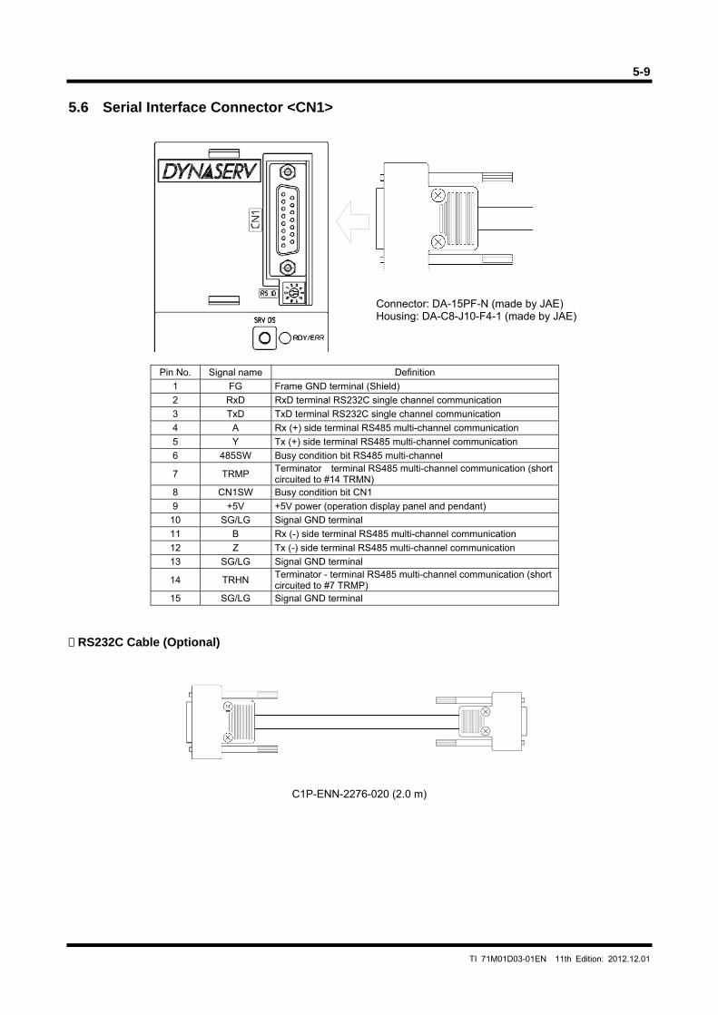
5-9
TI 71M01D03-01EN 11th Edition: 2012.12.01
5.6 Serial Interface Connector <CN1>
Pin No. Signal name Definition
1 FG Frame GND terminal (Shield)
2 RxD RxD terminal RS232C single channel communication
3 TxD TxD terminal RS232C single channel communication
4 A Rx (+) side terminal RS485 multi-channel communication
5 Y Tx (+) side terminal RS485 multi-channel communication
6 485SW Busy condition bit RS485 multi-channel
7 TRMP Terminator terminal RS485 multi-channel communication (short circuited to #14 TRMN)
8 CN1SW Busy condition bit CN1
9 +5V +5V power (operation display panel and pendant)
10 SG/LG Signal GND terminal
11 B Rx (-) side terminal RS485 multi-channel communication
12 Z Tx (-) side terminal RS485 multi-channel communication
13 SG/LG Signal GND terminal
14 TRHN Terminator - terminal RS485 multi-channel communication (short circuited to #7 TRMP)
15 SG/LG Signal GND terminal
RS232C Cable (Optional)
C1P-ENN-2276-020 (2.0 m)
Connector: DA-15PF-N (made by JAE) Housing: DA-C8-J10-F4-1 (made by JAE)
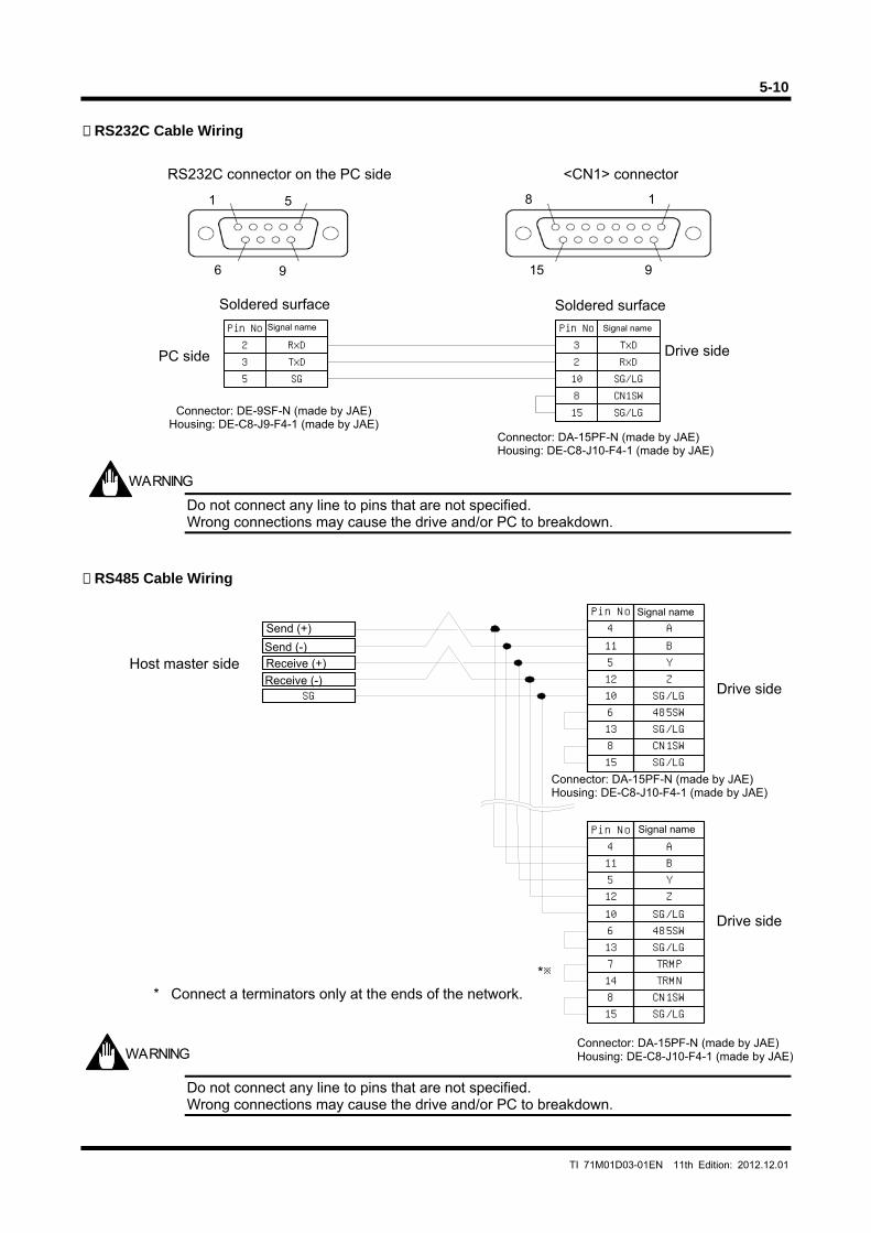
5-10
TI 71M01D03-01EN 11th Edition: 2012.12.01
RxD235
15
1023
8
Pin NoPin No
SGTxD
CN1SW
RxDTxD
SG/LG
SG/LG
RS232C Cable Wiring
Do not connect any line to pins that are not specified. Wrong connections may cause the drive and/or PC to breakdown.
RS485 Cable Wiring
Do not connect any line to pins that are not specified. Wrong connections may cause the drive and/or PC to breakdown.
WARNING
WARNING
<CN1> connectorRS232C connector on the PC side
Soldered surfaceSoldered surface
PC side Drive side
Signal nameSignal name
Connector: DE-9SF-N (made by JAE)Housing: DE-C8-J9-F4-1 (made by JAE)
Connector: DA-15PF-N (made by JAE) Housing: DE-C8-J10-F4-1 (made by JAE)
Pin No
147 TRMP
TRMN
SG
10
11
12
4
5
A
Y
SG/LG
B
Z
136 485SW
SG/LG
158 CN1SW
SG/LG
※
10
11
12
4
5
Pin NoA
Y
SG/LG
B
Z
158 CN1SW136 485SW
SG/LG
SG/LG
Drive side
Signal name
Host master side
Send (+)
Receive (+) Receive (-)
* Connect a terminators only at the ends of the network.
Drive side
Connector: DA-15PF-N (made by JAE)Housing: DE-C8-J10-F4-1 (made by JAE)
Signal name
Connector: DA-15PF-N (made by JAE)Housing: DE-C8-J10-F4-1 (made by JAE)
Send (-)
*
5 1
9 6 9 15
1 8
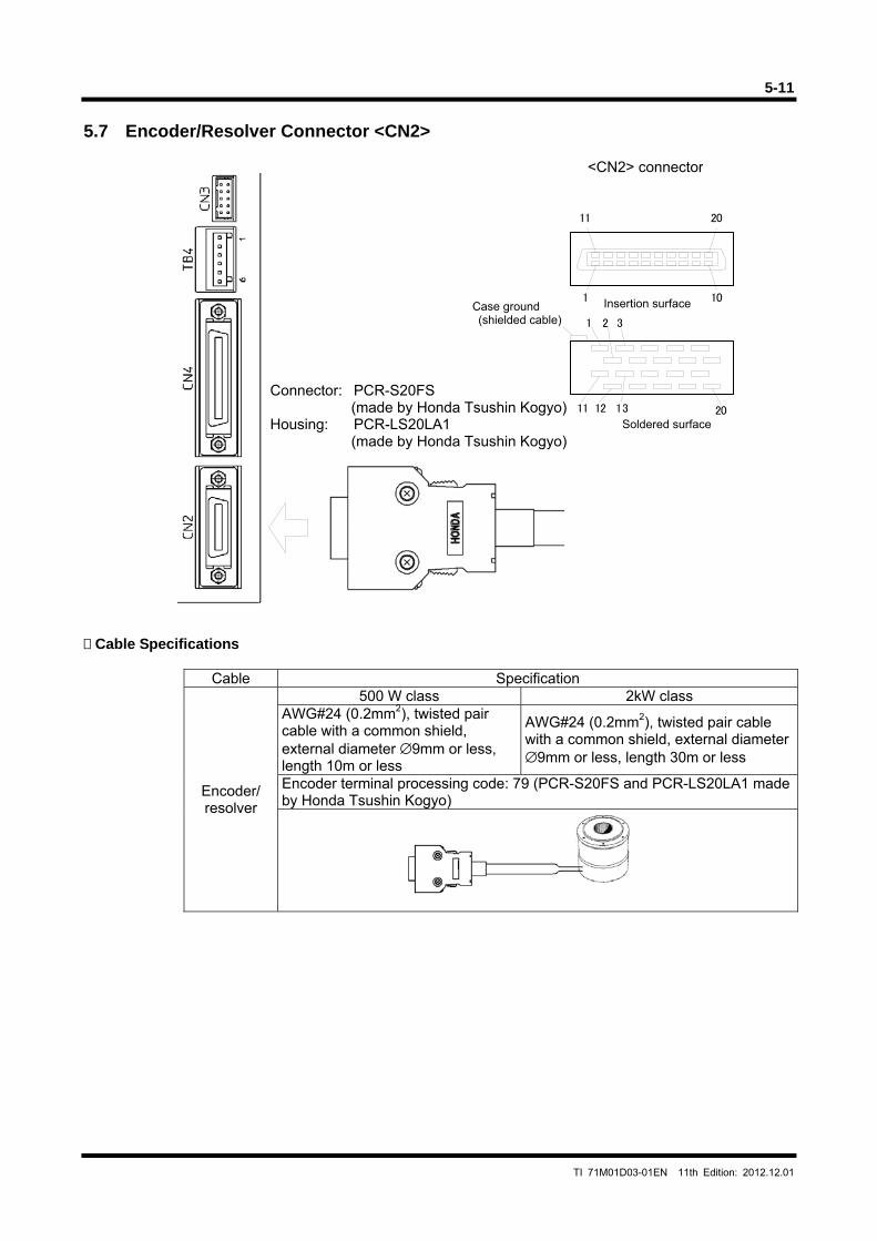
5-11
TI 71M01D03-01EN 11th Edition: 2012.12.01
1 32
11 1312 20
20
10
11
1
5.7 Encoder/Resolver Connector <CN2> Cable Specifications
Cable Specification
Encoder/ resolver
500 W class 2kW class AWG#24 (0.2mm2), twisted pair cable with a common shield, external diameter ∅9mm or less, length 10m or less
AWG#24 (0.2mm2), twisted pair cable with a common shield, external diameter ∅9mm or less, length 30m or less
Encoder terminal processing code: 79 (PCR-S20FS and PCR-LS20LA1 made by Honda Tsushin Kogyo)
Connector: PCR-S20FS (made by Honda Tsushin Kogyo)
Housing: PCR-LS20LA1 (made by Honda Tsushin Kogyo)
Case ground (shielded cable)
<CN2> connector
Insertion surface
Soldered surface
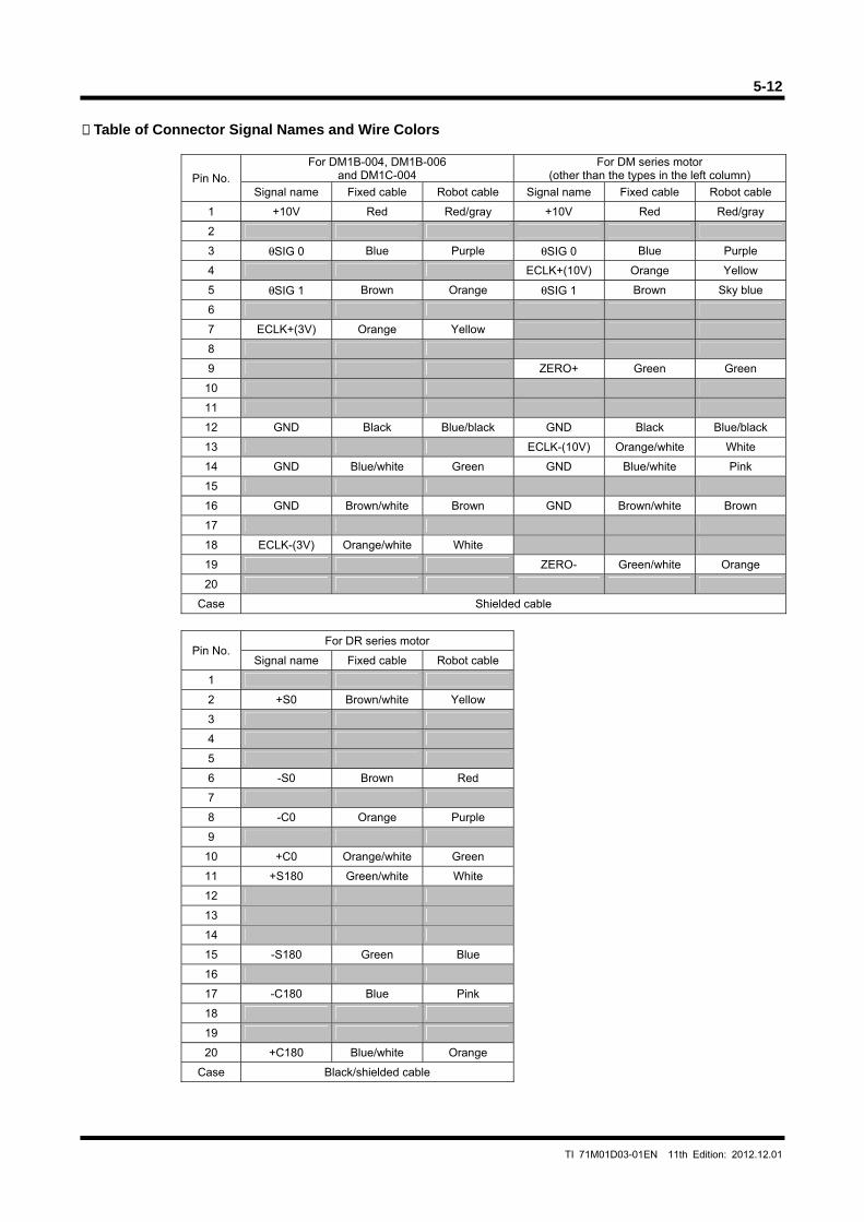
5-12
TI 71M01D03-01EN 11th Edition: 2012.12.01
Table of Connector Signal Names and Wire Colors
Pin No.
For DM1B-004, DM1B-006 and DM1C-004
For DM series motor (other than the types in the left column)
Signal name Fixed cable Robot cable Signal name Fixed cable Robot cable
1 +10V Red Red/gray +10V Red Red/gray
2
3 θSIG 0 Blue Purple θSIG 0 Blue Purple
4 ECLK+(10V) Orange Yellow
5 θSIG 1 Brown Orange θSIG 1 Brown Sky blue
6
7 ECLK+(3V) Orange Yellow
8
9 ZERO+ Green Green
10
11
12 GND Black Blue/black GND Black Blue/black
13 ECLK-(10V) Orange/white White
14 GND Blue/white Green GND Blue/white Pink
15
16 GND Brown/white Brown GND Brown/white Brown
17
18 ECLK-(3V) Orange/white White
19 ZERO- Green/white Orange
20
Case Shielded cable
Pin No. For DR series motor
Signal name Fixed cable Robot cable
1
2 +S0 Brown/white Yellow
3
4
5
6 -S0 Brown Red
7
8 -C0 Orange Purple
9
10 +C0 Orange/white Green
11 +S180 Green/white White
12
13
14
15 -S180 Green Blue
16
17 -C180 Blue Pink
18
19
20 +C180 Blue/white Orange
Case Black/shielded cable
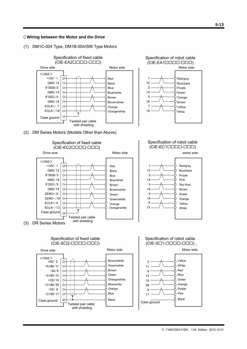
5-13
TI 71M01D03-01EN 11th Edition: 2012.12.01
+10V/ 1
GND/12
θSIG0/3
GND/14
θSIG1/5
GND/16
ECLK+/ 7
ECLK-/18
<CN2>
+10V/ 1
GND/12
θSIG0/3
GND/14
θSIG1/5
GND/16
ECLK+/4
ECLK-/13
<CN2>
ZERO+/9
ZERO-/19
(C1E-EC2--)
<CN2>+S0/ 2
+S180/11
-S0/6
-S180/15
+C0/10
+C180/20
-C0/ 8
-C180/17
1
12
3
14
5
16
7
18
1
12
3
14
5
16
9
19
4
13
2
11
6
15
10
20
8
17
(C1E-EC1--)
(C1E-S2--) (C1E-S1--)
Wiring between the Motor and the Drive
(1) DM1C-004 Type, DM1B-004/006 Type Motors (2) DM Series Motors (Models Other than Above) (3) DR Series Motors Twisted pair cable
with shielding
Motor sideDrive side
Red
Black
Blue
Blue/white
Brown
Brown/white
Orange
Orange/white
Case ground Twisted pair cable
with shielding
Motor side
Red/gray Blue/back
Purple
Green
Orange
Brown
Yellow
White
Specification of robot cable(CIE-EA1-)
Specification of fixed cable(CIE-EA2-)
Motor sideDrive side
Case ground
Motor side
Red/gray
Blue/back
Purple
Pink
Sky blue
Brown
Yellow
White
Green
Orange
Twisted pair cable with shielding
Red
Black
Blue
Blue/white
Brown
Brown/white
Orange
Green
Green/white
Orange/white
Motor sideDrive side Motor side
Case ground
Brown/white
Green/white
Brown
Green
Orange/white
Blue/white
Orange
Blue
Black
Yellow
White
Red
Blue
Green
Orange
Purple
Pink
Black
Specification of fixed cable(CIE-S2--)
Specification of robot cable(CIE-S1--)
Specification of fixed cable(CIE-EC2-)
Specification of robot cable(CIE-EC1-)
Case ground
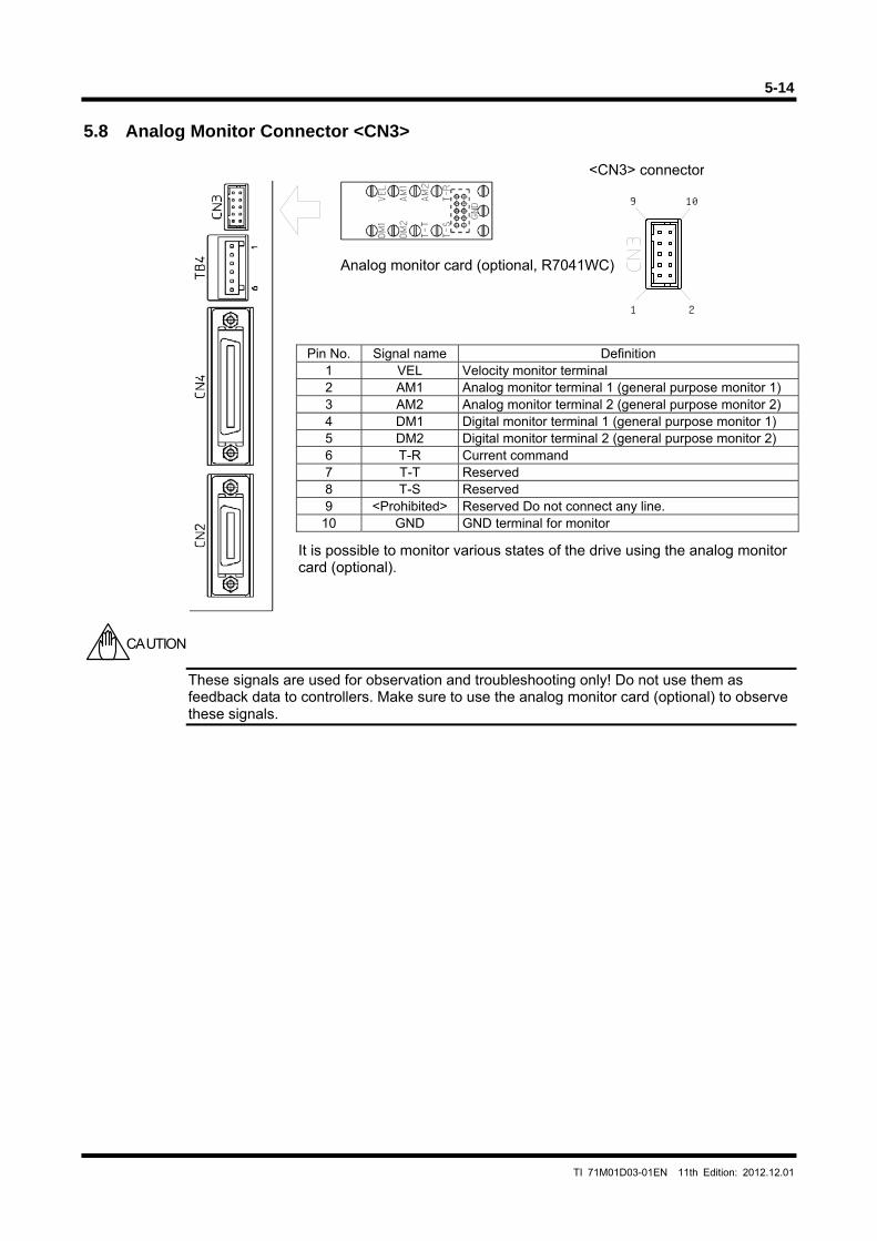
5-14
TI 71M01D03-01EN 11th Edition: 2012.12.01
1 2
109
5.8 Analog Monitor Connector <CN3>
Pin No. Signal name Definition 1 VEL Velocity monitor terminal 2 AM1 Analog monitor terminal 1 (general purpose monitor 1) 3 AM2 Analog monitor terminal 2 (general purpose monitor 2) 4 DM1 Digital monitor terminal 1 (general purpose monitor 1) 5 DM2 Digital monitor terminal 2 (general purpose monitor 2) 6 T-R Current command 7 T-T Reserved 8 T-S Reserved 9 <Prohibited> Reserved Do not connect any line.
10 GND GND terminal for monitor
These signals are used for observation and troubleshooting only! Do not use them as feedback data to controllers. Make sure to use the analog monitor card (optional) to observe these signals.
CAUTION
It is possible to monitor various states of the drive using the analog monitor card (optional).
Analog monitor card (optional, R7041WC)
<CN3> connector
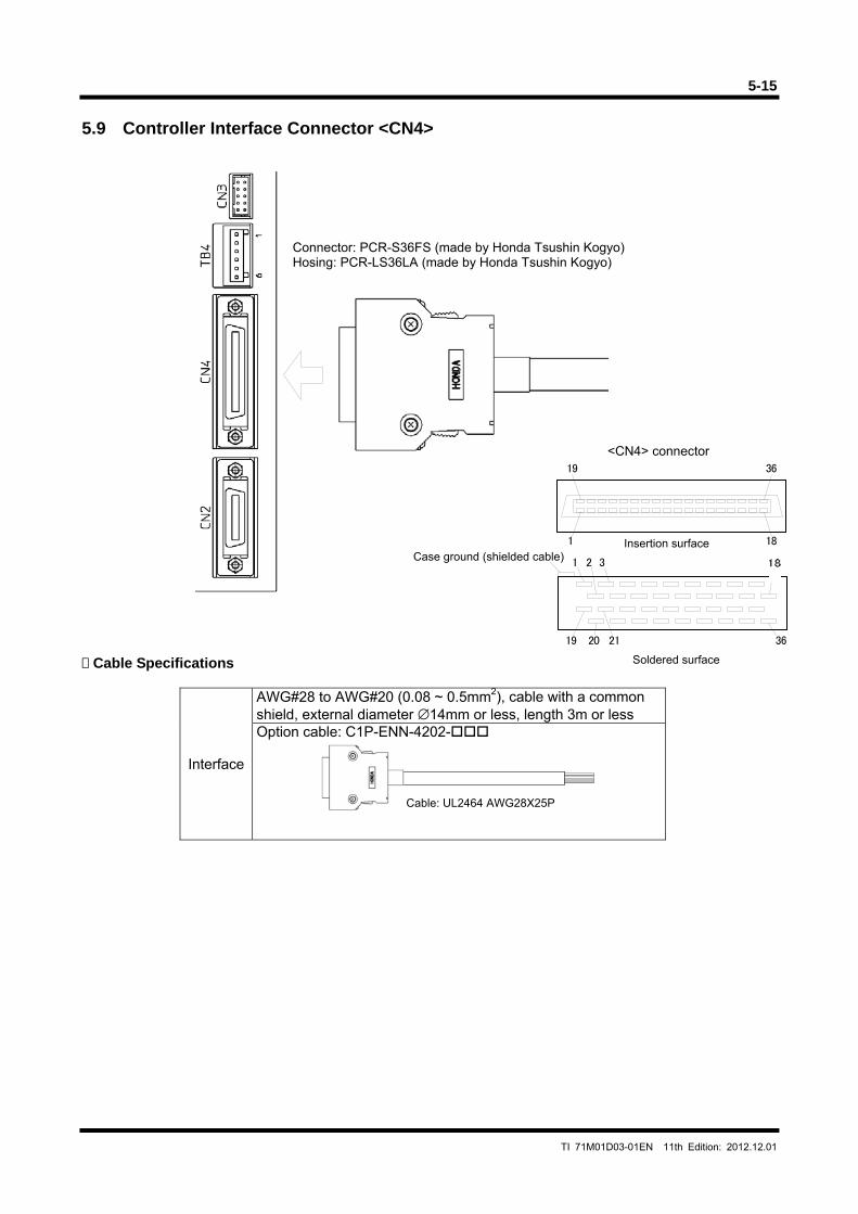
5-15
TI 71M01D03-01EN 11th Edition: 2012.12.01
19 36
1 32
1 18
36212019
5.9 Controller Interface Connector <CN4> Cable Specifications
Interface
AWG#28 to AWG#20 (0.08 ~ 0.5mm2), cable with a common shield, external diameter ∅14mm or less, length 3m or less Option cable: C1P-ENN-4202-
Connector: PCR-S36FS (made by Honda Tsushin Kogyo)Hosing: PCR-LS36LA (made by Honda Tsushin Kogyo)
<CN4> connector
Case ground (shielded cable)Insertion surface
Soldered surface
Cable: UL2464 AWG28X25P
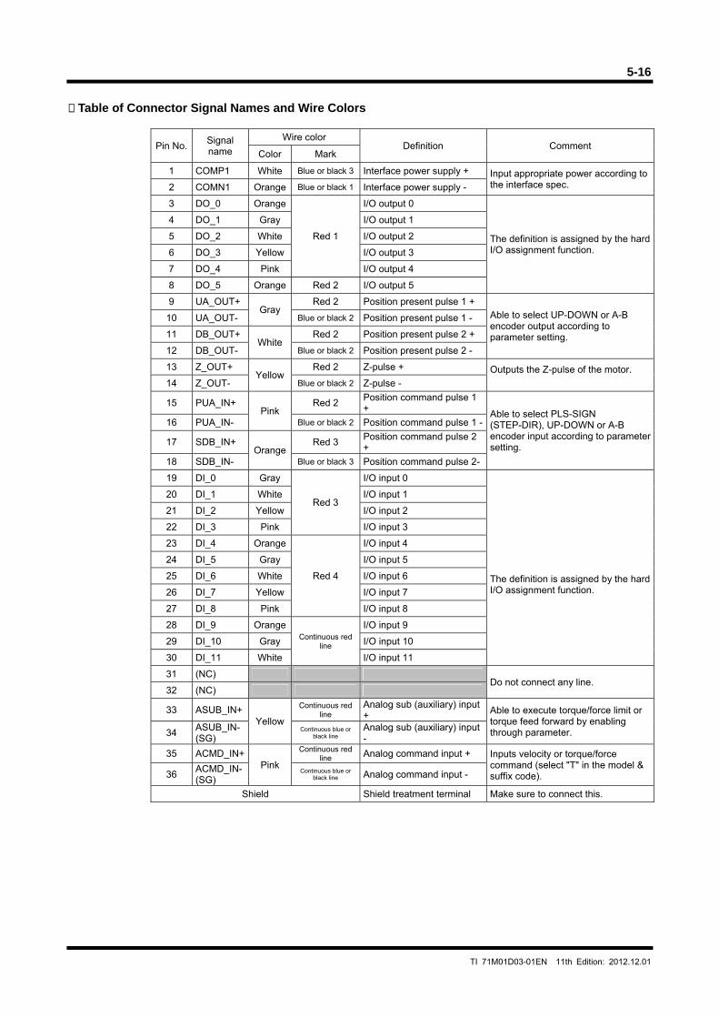
5-16
TI 71M01D03-01EN 11th Edition: 2012.12.01
Table of Connector Signal Names and Wire Colors
Pin No. Signal name
Wire color Definition Comment
Color Mark
1 COMP1 White Blue or black 3 Interface power supply + Input appropriate power according to the interface spec. 2 COMN1 Orange Blue or black 1 Interface power supply -
3 DO_0 Orange
Red 1
I/O output 0
The definition is assigned by the hard I/O assignment function.
4 DO_1 Gray I/O output 1
5 DO_2 White I/O output 2
6 DO_3 Yellow I/O output 3
7 DO_4 Pink I/O output 4
8 DO_5 Orange Red 2 I/O output 5
9 UA_OUT+ Gray
Red 2 Position present pulse 1 + Able to select UP-DOWN or A-B encoder output according to parameter setting.
10 UA_OUT- Blue or black 2 Position present pulse 1 -
11 DB_OUT+ White
Red 2 Position present pulse 2 +
12 DB_OUT- Blue or black 2 Position present pulse 2 -
13 Z_OUT+ Yellow
Red 2 Z-pulse + Outputs the Z-pulse of the motor. 14 Z_OUT- Blue or black 2 Z-pulse -
15 PUA_IN+ Pink
Red 2 Position command pulse 1 +
Able to select PLS-SIGN (STEP-DIR), UP-DOWN or A-B encoder input according to parameter setting.
16 PUA_IN- Blue or black 2 Position command pulse 1 -
17 SDB_IN+ Orange
Red 3 Position command pulse 2 +
18 SDB_IN- Blue or black 3 Position command pulse 2-
19 DI_0 Gray
Red 3
I/O input 0
The definition is assigned by the hard I/O assignment function.
20 DI_1 White I/O input 1
21 DI_2 Yellow I/O input 2
22 DI_3 Pink I/O input 3
23 DI_4 Orange
Red 4
I/O input 4
24 DI_5 Gray I/O input 5
25 DI_6 White I/O input 6
26 DI_7 Yellow I/O input 7
27 DI_8 Pink I/O input 8
28 DI_9 Orange Continuous red
line
I/O input 9
29 DI_10 Gray I/O input 10
30 DI_11 White I/O input 11
31 (NC) Do not connect any line.
32 (NC)
33 ASUB_IN+ Yellow
Continuous red line
Analog sub (auxiliary) input + Able to execute torque/force limit or
torque feed forward by enabling through parameter. 34
ASUB_IN- (SG)
Continuous blue or black line
Analog sub (auxiliary) input -
35 ACMD_IN+ Pink
Continuous redline Analog command input + Inputs velocity or torque/force
command (select "T" in the model & suffix code). 36
ACMD_IN- (SG)
Continuous blue or black line Analog command input -
Shield Shield treatment terminal Make sure to connect this.
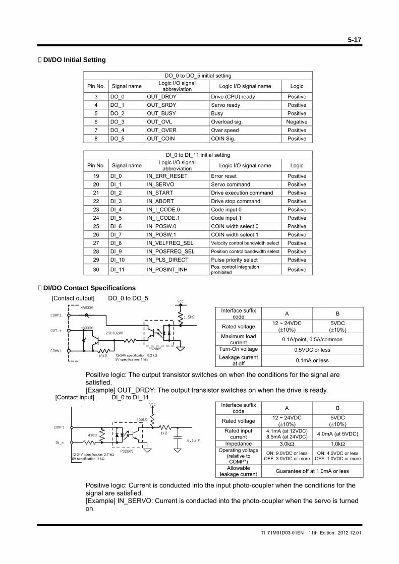
5-17
TI 71M01D03-01EN 11th Edition: 2012.12.01
Vcc
470Ω
COMP1
IN_*
100kΩ
1kΩ
0.1μF
PS2805
PS2805
COMP1
OUT_*
COMN110kΩ
MA8330
MA83302SD1820A
Vcc
1.5kΩ
DI/DO Initial Setting
DO_0 to DO_5 initial setting
Pin No. Signal name Logic I/O signal
abbreviation Logic I/O signal name Logic
3 DO_0 OUT_DRDY Drive (CPU) ready Positive
4 DO_1 OUT_SRDY Servo ready Positive
5 DO_2 OUT_BUSY Busy Positive
6 DO_3 OUT_OVL Overload sig. Negative
7 DO_4 OUT_OVER Over speed Positive
8 DO_5 OUT_COIN COIN Sig. Positive
DI_0 to DI_11 initial setting
Pin No. Signal name Logic I/O signal
abbreviation Logic I/O signal name Logic
19 DI_0 IN_ERR_RESET Error reset Positive
20 DI_1 IN_SERVO Servo command Positive
21 DI_2 IN_START Drive execution command Positive
22 DI_3 IN_ABORT Drive stop command Positive
23 DI_4 IN_I_CODE.0 Code input 0 Positive
24 DI_5 IN_I_CODE.1 Code input 1 Positive
25 DI_6 IN_POSW.0 COIN width select 0 Positive
26 DI_7 IN_POSW.1 COIN width select 1 Positive
27 DI_8 IN_VELFREQ_SEL Velocity control bandwidth select Positive
28 DI_9 IN_POSFREQ_SEL Position control bandwidth select Positive
29 DI_10 IN_PLS_DIRECT Pulse priority select Positive
30 DI_11 IN_POSINT_INH Pos. control integration prohibited Positive
DI/DO Contact Specifications
Interface suffix code
A B
Rated voltage 12 ~ 24VDC
(±10%) 5VDC (±10%)
Maximum load current
0.1A/point, 0.5A/common
Turn-On voltage 0.5VDC or less Leakage current
at off 0.1mA or less
Positive logic: The output transistor switches on when the conditions for the signal are satisfied. [Example] OUT_DRDY: The output transistor switches on when the drive is ready.
Interface suffix
code A B
Rated voltage 12 ~ 24VDC
(±10%) 5VDC (±10%)
Rated input current
4.1mA (at 12VDC) 8.5mA (at 24VDC) 4.0mA (at 5VDC)
Impedance 3.0kΩ 1.0kΩ Operating voltage
(relative to COMP*)
ON: 9.0VDC or less OFF: 3.0VDC or more
ON: 4.0VDC or lessOFF: 1.0VDC or more
Allowable leakage current
Guarantee off at 1.0mA or less
Positive logic: Current is conducted into the input photo-coupler when the conditions for the signal are satisfied. [Example] IN_SERVO: Current is conducted into the photo-coupler when the servo is turned on.
12-24V specification: 8.2 kΩ 5V specification: 1 kΩ
12-24V specification: 2.7 kΩ 5V specification: 1 kΩ
[Contact output] DO_0 to DO_5
[Contact input] DI_0 to DI_11
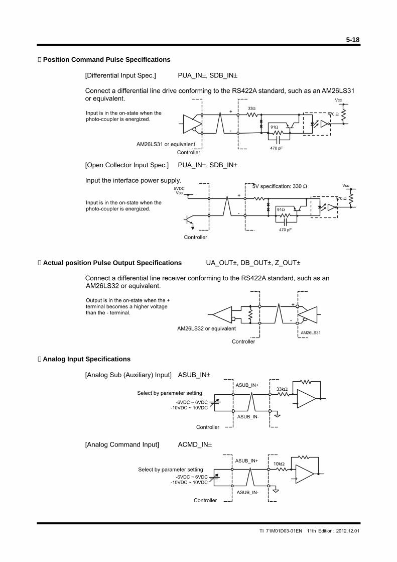
5-18
TI 71M01D03-01EN 11th Edition: 2012.12.01
Position Command Pulse Specifications
[Differential Input Spec.] PUA_IN±, SDB_IN±
Connect a differential line drive conforming to the RS422A standard, such as an AM26LS31 or equivalent.
Input is in the on-state when the photo-coupler is energized.
[Open Collector Input Spec.] PUA_IN±, SDB_IN±
Input the interface power supply.
Input is in the on-state when the photo-coupler is energized.
Actual position Pulse Output Specifications UA_OUT±, DB_OUT±, Z_OUT±
Connect a differential line receiver conforming to the RS422A standard, such as an AM26LS32 or equivalent.
Output is in the on-state when the + terminal becomes a higher voltage than the - terminal.
Analog Input Specifications
[Analog Sub (Auxiliary) Input] ASUB_IN±
[Analog Command Input] ACMD_IN±
AM26LS31 or equivalent
Controller
33kΩASUB_IN+
ASUB_IN-
10kΩASUB_IN+
ASUB_IN-
+
-
470 pF
470 Ω
Vcc
91Ω
5V specification: 330 Ω
Controller
+
-
470 pF
470 Ω
Vcc
91Ω
5VDCVcc
AM26LS32 or equivalent
Controller
+
-
AM26LS31
Controller
Select by parameter setting
-6VDC ~ 6VDC-10VDC ~ 10VDC
+
-
Controller
Select by parameter setting-6VDC ~ 6VDC
-10VDC ~ 10VDC+
-
33Ω
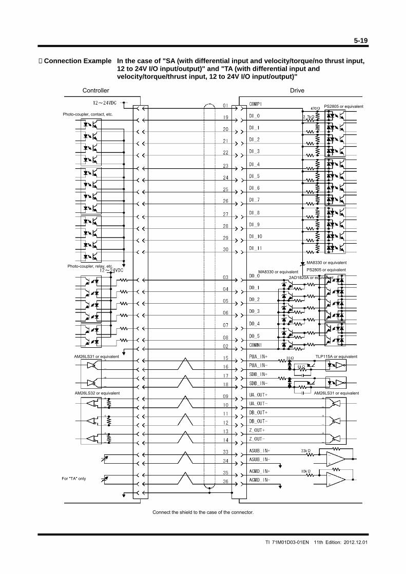
5-19
TI 71M01D03-01EN 11th Edition: 2012.12.01
Connection Example In the case of "SA (with differential input and velocity/torque/no thrust input,
12 to 24V I/O input/output)" and "TA (with differential input and velocity/torque/thrust input, 12 to 24V I/O input/output)"
Connect the shield to the case of the connector.
PS2805 or equivalent
TLP115A or equivalent
MA8330 or equivalent
MA8330 or equivalent
2AD1820A or equivalent
AM26LS31 or equivalent
AM26LS31 or equivalent
AM26LS32 or equivalent
Controller
Photo-coupler, contact, etc.
Photo-coupler, relay, etc.
For "TA" only
Drive
PS2805 or equivalent
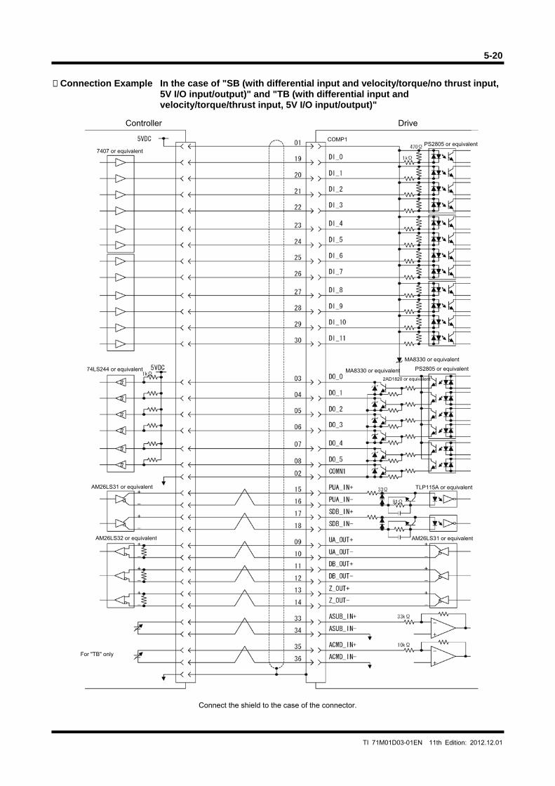
5-20
TI 71M01D03-01EN 11th Edition: 2012.12.01
Connection Example In the case of "SB (with differential input and velocity/torque/no thrust input,
5V I/O input/output)" and "TB (with differential input and velocity/torque/thrust input, 5V I/O input/output)"
Connect the shield to the case of the connector.
PS2805 or equivalent
Controller
For "TB" only
Drive
7407 or equivalent
MA8330 or equivalent
74LS244 or equivalent MA8330 or equivalent PS2805 or equivalent
2AD1820 or equivalent
TLP115A or equivalent
AM26LS31 or equivalent
AM26LS31 or equivalent
AM26LS32 or equivalent
COMP1
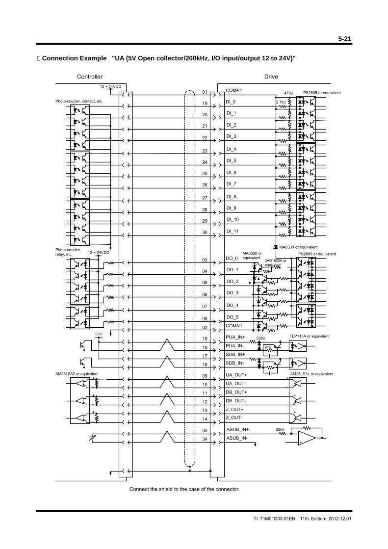
5-21
TI 71M01D03-01EN 11th Edition: 2012.12.01
Connection Example "UA (5V Open collector/200kHz, I/O input/output 12 to 24V)"
5VDC
Drive
ASUB_IN+
ASUB_IN-
33
34
Z_OUT-
Z_OUT+
DB_OUT+
DB_OUT-
UA_OUT+
UA_OUT-
PUA_IN+
PUA_IN-
SDB_IN+
SDB_IN-
DO_0
COMN1
COMP1
DI_0
91Ω
330Ω
470Ω
2.7kΩ
PS2805 or equivalent
TLP115A or equivalent
+
-
+
-
+
-
MA8330 orequivalent
MA8330 or equivalent
2AD1820A orequivalent
PS2805 or equivalent
+
-
+
-
+
-
AM26LS31 or equivalentAM26LS32 or equivalent
12 ~ 24VDC
12 ~ 24VDC
Controller
09
10
11
12
13
14
15
16
17
18
03
04
05
06
07
08
02
01
19
20
21
22
23
24
25
26
27
28
29
30
Connect the shield to the case of the connector.
Photo-coupler, contact, etc.
Photo-coupler,relay, etc.
DI_1
DI_2
DI_3
DI_4
DI_5
DI_6
DI_7
DI_8
DI_9
DI_10
DI_11
DO_1
DO_2
DO_3
DO_4
DO_5
33kΩ
+
-
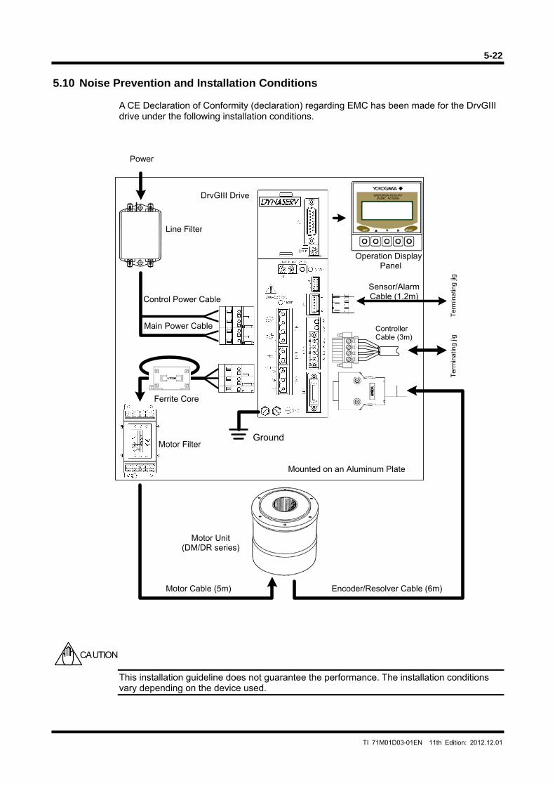
5-22
TI 71M01D03-01EN 11th Edition: 2012.12.01
5.10 Noise Prevention and Installation Conditions
A CE Declaration of Conformity (declaration) regarding EMC has been made for the DrvGIII drive under the following installation conditions.
This installation guideline does not guarantee the performance. The installation conditions vary depending on the device used.
CAUTION
Operation DisplayPanel
Motor Filter
Motor Unit (DM/DR series)
Motor Cable (5m)
Line Filter
Main Power Cable
Control Power Cable
Controller Cable (3m)
Ter
min
atin
g jig
Ter
min
atin
g jig
Encoder/Resolver Cable (6m)
Sensor/AlarmCable (1.2m)
Mounted on an Aluminum Plate
Ferrite Core
DrvGIII Drive
Power
Ground
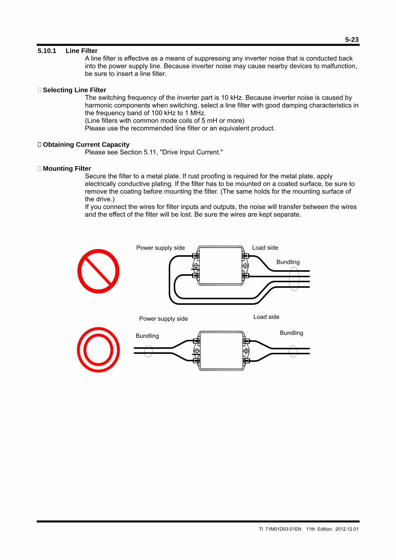
5-23
TI 71M01D03-01EN 11th Edition: 2012.12.01
5.10.1 Line Filter A line filter is effective as a means of suppressing any inverter noise that is conducted back into the power supply line. Because inverter noise may cause nearby devices to malfunction, be sure to insert a line filter.
Selecting Line Filter
The switching frequency of the inverter part is 10 kHz. Because inverter noise is caused by harmonic components when switching, select a line filter with good damping characteristics in the frequency band of 100 kHz to 1 MHz. (Line filters with common mode coils of 5 mH or more) Please use the recommended line filter or an equivalent product.
Obtaining Current Capacity
Please see Section 5.11, "Drive Input Current." Mounting Filter
Secure the filter to a metal plate. If rust proofing is required for the metal plate, apply electrically conductive plating. If the filter has to be mounted on a coated surface, be sure to remove the coating before mounting the filter. (The same holds for the mounting surface of the drive.) If you connect the wires for filter inputs and outputs, the noise will transfer between the wires and the effect of the filter will be lost. Be sure the wires are kept separate.
Power supply side Load side
Bundling
Power supply side Load side
Bundling Bundling
5-24
TI 71M01D03-01EN 11th Edition: 2012.12.01
5.10.2 Ferrite Core 1
The ferrite core 1 is effective as a means of suppressing noise radiating from motor cables. Mount it on a motor cable as close to the drive as possible. The ferrite core 1 is not required if the drive is installed in a metal control panel/equipment and does not affect devices located within the same equipment.
5.10.3 Ferrite Core 2
Ferrite core 2 is effective as a means of suppressing motor vibration caused by noise conducted into the motor cables and encoder/resolver cable. Conductive noise is caused by the capacitive and inductive coupling that occurs when cables are wired in parallel, thereby acting as noise sources. Mount it on a motor cable as close to the drive as possible. Ferrite core 2 is not required if there is no noise source that may cause motor vibration in the same equipment.
5.10.4 Motor Filter
A motor filter is effective as a means of suppressing the common mode noise generated by an inverter. Common mode noise is caused by high-frequency harmonic components in the current due to switching in the inverter, which is conducted via the coupling capacity between motor cable and motor coil and ground. A motor filter effectively suppresses high-frequency common mode noise current. If a CCD camera or measurement instrument is mounted on a platform where the length of a motor cable exceeds 10m, in particular, the ground may become unstable due to the common mode noise current, leading to a device malfunction. Attach the filter to a motor cable as close to the drive as possible. Secure it to a metal plate in the same way as for a line filter. However, be careful not to connect the input and output wires of a filter. A motor filter is not required if the motor cables are short or there is no effect on other devices located within the equipment.
5.10.5 Shielding of Cables
The shielding of cables is effective as a means of suppressing motor malfunction due to external noise and inverter noise, and in suppressing the influence on other devices resulting from the inverter harmonic components and noise irradiated from the CPU clock. The shielding of motor cables and encoder/resolver cables must be securely connected to grounds on the drive and motor sides. Such shielding lowers the high-frequency impedance to the ground between the motor and drive, and it suppresses the malfunctioning of the encoder due to external noise and inverter noise. For a controller cable, securely connect the shielding to the ground on both the drive and controller sides. Such shielding lowers the impedance to the ground between the controller and drive, and it suppresses the malfunction of pulse position command input and analog velocity command.
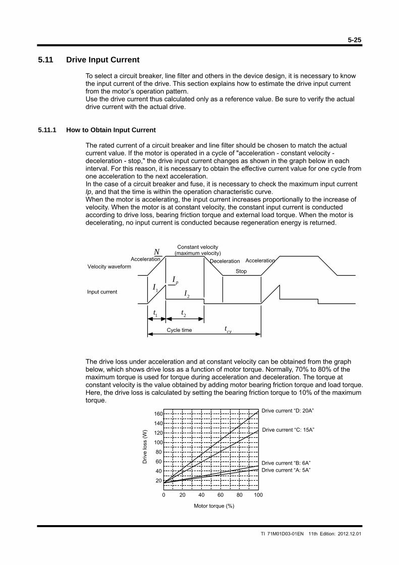
5-25
TI 71M01D03-01EN 11th Edition: 2012.12.01
1I2I
pI
2t
cyt
N
1t
0 20 40 60 80 100
20
40
60
80
100
120
140
160
5.11 Drive Input Current
To select a circuit breaker, line filter and others in the device design, it is necessary to know the input current of the drive. This section explains how to estimate the drive input current from the motor’s operation pattern. Use the drive current thus calculated only as a reference value. Be sure to verify the actual drive current with the actual drive.
5.11.1 How to Obtain Input Current
The rated current of a circuit breaker and line filter should be chosen to match the actual current value. If the motor is operated in a cycle of "acceleration - constant velocity - deceleration - stop," the drive input current changes as shown in the graph below in each interval. For this reason, it is necessary to obtain the effective current value for one cycle from one acceleration to the next acceleration. In the case of a circuit breaker and fuse, it is necessary to check the maximum input current Ip, and that the time is within the operation characteristic curve. When the motor is accelerating, the input current increases proportionally to the increase of velocity. When the motor is at constant velocity, the constant input current is conducted according to drive loss, bearing friction torque and external load torque. When the motor is decelerating, no input current is conducted because regeneration energy is returned.
The drive loss under acceleration and at constant velocity can be obtained from the graph below, which shows drive loss as a function of motor torque. Normally, 70% to 80% of the maximum torque is used for torque during acceleration and deceleration. The torque at constant velocity is the value obtained by adding motor bearing friction torque and load torque. Here, the drive loss is calculated by setting the bearing friction torque to 10% of the maximum torque.
Velocity waveform
Input current
Acceleration
Constant velocity (maximum velocity)
Deceleration
Stop
Acceleration
Cycle time
Driv
e lo
ss (
W)
Motor torque (%)
Drive current “D: 20A”
Drive current “C: 15A”
Drive current “B: 6A” Drive current “A: 5A”
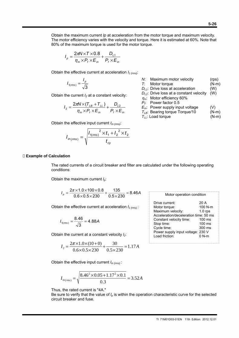
5-26
TI 71M01D03-01EN 11th Edition: 2012.12.01
inf
L
infmp EP
D
EP
TNI
×+
××××= 18.02
ηπ
3)(1
prms
II =
inf
L
infm
LLLB
EP
D
EP
TTNI
×+
××+×
= 22
)(2
ηπ
cy
rms
rmsin t
tItII 2
221
2)(1
)(
×+×=
AI 17.12305.0
302305.06.0
)010(0.122 =
×+
××+××= π
Obtain the maximum current lp at acceleration from the motor torque and maximum velocity. The motor efficiency varies with the velocity and torque. Here it is estimated at 60%. Note that 80% of the maximum torque is used for the motor torque.
Obtain the effective current at acceleration I1 (rms):
Obtain the current I2 at a constant velocity:
Obtain the effective input current Iin (rms): Example of Calculation
The rated currents of a circuit breaker and filter are calculated under the following operating conditions: Obtain the maximum current lp:
Obtain the effective current at acceleration l1 (rms) :
Obtain the current at a constant velocity l2:
Obtain the effective input current lin (rms) :
Thus, the rated current is "4A." Be sure to verify that the value of lp is within the operation characteristic curve for the selected circuit breaker and fuse.
N: Maximum motor velocity (rps) T: Motor torque (N-m)DL1: Drive loss at acceleration (W) DL2: Drive loss at a constant velocity (W) ηm: Motor efficiency 60% Pf: Power factor 0.5 Ein: Power supply input voltage (V) TLB: Bearing torque Torque/10 (N-m)TLL: Load torque (N-m)
Motor operation condition
Drive current: 20 A Motor torque: 100 N-m Maximum velocity: 1.0 rps Acceleration/deceleration time: 50 ms Constant velocity time: 100 ms Stop time: 100 ms Cycle time: 300 ms Power supply input voltage: 230 V Load friction: 0 N-m
AIp 46.82305.0
135
2305.06.0
8.01000.12 =×
+××
×××= π
AI rms 88.43
46.8)(1 ==
AI rmsin 52.33.0
1.017.105.046.8 22
)( =×+×=
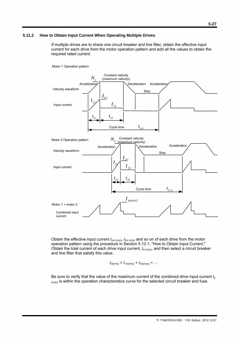
5-27
TI 71M01D03-01EN 11th Edition: 2012.12.01
21I22I
pI 2
22t
cyt2
2N
21t
11I12I
pI1
12t
cyt1
1N
11t
(max)pI
5.11.2 How to Obtain Input Current When Operating Multiple Drives
If multiple drives are to share one circuit breaker and line filter, obtain the effective input current for each drive from the motor operation pattern and add all the values to obtain the required rated current.
Obtain the effective input current l1in (rms), l2in (rms) and so on of each drive from the motor operation pattern using the procedure in Section 5.12.1, "How to Obtain Input Current." Obtain the total current of each drive input current, lin (rms), and then select a circuit breaker and line filter that satisfy this value.
Iin(rms) = I1in(rms) + I2in(rms) + …
Be sure to verify that the value of the maximum current of the combined drive input current lp
(max) is within the operation characteristics curve for the selected circuit breaker and fuse.
Motor 1 Operation pattern
Velocity waveform
Input current
Acceleration
Constant velocity (maximum velocity)
Deceleration
Stop
Cycle time
Acceleration
Motor 1 + motor 2
Combined input current
Motor 2 Operation pattern
Velocity waveform
Input current
Acceleration
Constant velocity (maximum velocity)
Deceleration
Stop
Cycle time
Acceleration
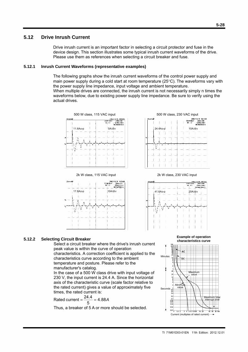
5-28
TI 71M01D03-01EN 11th Edition: 2012.12.01
10A/div24.4Ao-p5A/div11.6Ao-p
20A/div41.6Ao-p10A/div17.8Ao-p
5.12 Drive Inrush Current
Drive inrush current is an important factor in selecting a circuit protector and fuse in the device design. This section illustrates some typical inrush current waveforms of the drive. Please use them as references when selecting a circuit breaker and fuse.
5.12.1 Inrush Current Waveforms (representative examples)
The following graphs show the inrush current waveforms of the control power supply and main power supply during a cold start at room temperature (25°C). The waveforms vary with the power supply line impedance, input voltage and ambient temperature. When multiple drives are connected, the inrush current is not necessarily simply n times the waveforms below, due to existing power supply line impedance. Be sure to verify using the actual drives.
500 W class, 115 VAC input 500 W class, 230 VAC input 5.12.2 Selecting Circuit Breaker
Select a circuit breaker where the drive's inrush current peak value is within the curve of operation characteristics. A correction coefficient is applied to the characteristics curve according to the ambient temperature and posture. Please refer to the manufacturer's catalog. In the case of a 500 W class drive with input voltage of 230 V, the input current is 24.4 A. Since the horizontal axis of the characteristic curve (scale factor relative to the rated current) gives a value of approximately five times, the rated current is:
A88.45
24.4 current Rated ==
Thus, a breaker of 5 A or more should be selected.
2k W class, 115 VAC input 2k W class, 230 VAC input
Example of operation characteristics curve
Minutes
Seconds
Minimum value
Maximum value
Maximum total interrupt time
Current (multiples of rated current)
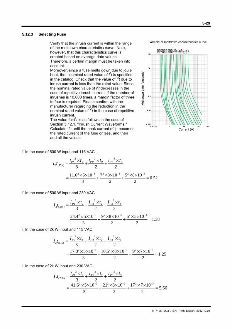
5-29
TI 71M01D03-01EN 11th Edition: 2012.12.01
5.12.3 Selecting Fuse
Verify that the inrush current is within the range of the meltdown characteristics curve. Note, however, that this characteristics curve is created based on average data values. Therefore, a certain margin must be taken into account. Moreover, since a fuse melts down due to joule heat, the nominal rated value of l2t is specified in the catalog. Check that the value of l2t due to inrush current is less than the rated value. Since the nominal rated value of l2t decreases in the case of repetitive inrush current, if the number of inrushes is 10,000 times, a margin factor of three to four is required. Please confirm with the manufacturer regarding the reduction in the nominal rated value of l2t in the case of repetitive inrush current. The value for l2t is as follows in the case of Section 5.12.1, "Inrush Current Waveforms." Calculate l2t until the peak current of lp becomes the rated current of the fuse or less, and then add all the values.
In the case of 500 W input and 115 VAC
In the case of 500 W input and 230 VAC
In the case of 2k W input and 115 VAC
In the case of 2k W input and 230 VAC
2233
232
222
21
)115(2
tItItItI PPP ×
+×
+×
=
52.02
10852
10873
1056.11 323232
=××+××+××=−−−
2233
232
222
21
)230(2tItItI
tI PPP ×+×+×=
38.12
10552
10893
1054.24 323232
=××+××+××=−−−
2233
232
222
21
)115(2tItItI
tI PPP ×+×+×=
25.12
10792
1085.103
1058.17 323232
=××+××+××=−−−
2233
232
222
21
)230(2tItItI
tI PPP ×+×+×=
66.52
107172
108213
1056.41 323232
=××+××+××=−−−
Example of meltdown characteristics curve
Current (A)
Mel
tdow
n tim
e (s
econ
ds)

Blank Page
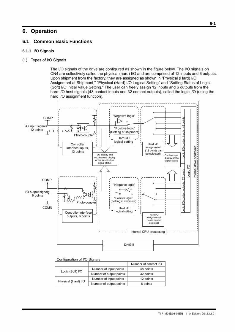
6-1
TI 71M01D03-01EN 11th Edition: 2012.12.01
6. Operation 6.1 Common Basic Functions 6.1.1 I/O Signals (1) Types of I/O Signals
The I/O signals of the drive are configured as shown in the figure below. The I/O signals on CN4 are collectively called the physical (hard) I/O and are comprised of 12 inputs and 6 outputs. Upon shipment from the factory, they are assigned as shown in "Physical (Hard) I/O Assignment at Shipment," "Physical (Hard) I/O Logical Setting" and "Setting Status of Logic (Soft) I/O Initial Value Setting." The user can freely assign 12 inputs and 6 outputs from the hard I/O host signals (48 contact inputs and 32 contact outputs), called the logic I/O (using the hard I/O assignment function).
Configuration of I/O Signals Number of contact I/O
Logic (Soft) I/O Number of input points 48 points
Number of output points 32 points
Physical (Hard) I/O Number of input points 12 points
Number of output points 6 points
"Positive logic" (Setting at shipment)
"Negative logic"COMP
I/O input signals, 12 points
Photo-coupler
Hard I/O assig-nment
(12 points can be selected)
Oscilloscope display of the signal status
Controller interface inputs,
12 points
Inte
rnal
driv
e co
ntr
olle
r
Internal CPU processing
DrvGIII
Photo-coupler
Hard I/O assignment (6 points can be
selected)
"Positive logic" (Setting at shipment)
"Negative logic"
I/O display and oscilloscope display of the input/output
signal status
Logi
c I/O
con
tact
out
puts
, 32
poin
tsLo
gic
I/O c
onta
ct in
puts
, 48
poi
nts
Hard I/O logical setting
Hard I/O logical setting
Logi
c I/
O
Controller interface outputs, 6 points
COMP
COMN
I/O output signals, 6 points
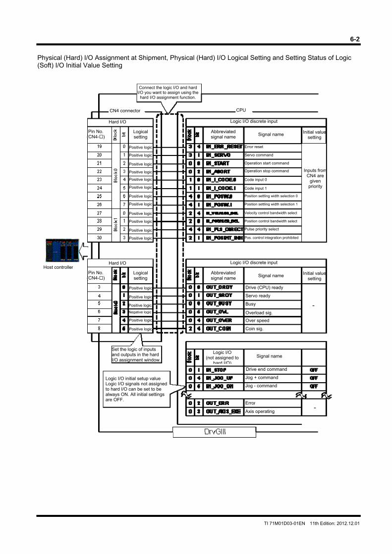
6-2
TI 71M01D03-01EN 11th Edition: 2012.12.01
Physical (Hard) I/O Assignment at Shipment, Physical (Hard) I/O Logical Setting and Setting Status of Logic (Soft) I/O Initial Value Setting
CN4 connector
Logic I/O discrete input
Abbreviated signal name
Hard I/O
Logical setting
Positive logic
Pin No. (CN4-)
Initial valuesetting Signal name
Operation start command
Operation stop command
Code input 0
Code input 1
Position control bandwidth select
Pos. control integration prohibited
Velocity control bandwidth select
Servo command
Error reset
Position settling width selection 0
Position settling width selection 1
Pulse priority select
Inputs fromCN4 are
given priority
Over speed
Overload sig.
Coin sig.
Drive (CPU) ready
Servo ready
Busy
Set the logic of inputs and outputs in the hard I/O assignment window.
Logic I/O (not assigned to
hard I/O)
Jog + command
Jog - command
Signal name
Logic I/O initial setup value Logic I/O signals not assigned to hard I/O can be set to be always ON. All initial settings are OFF.
Drive end command
Host controller
Axis operating
Error-
Positive logic
Positive logic
Positive logic
Positive logic
Positive logic
Positive logic
Positive logic
Positive logic
Positive logic
Positive logic
Positive logic
Connect the logic I/O and hard I/O you want to assign using the
hard I/O assignment function.
CPU
-
Positive logic
Positive logic
Positive logic
Positive logic
Positive logic
Logic I/O discrete input
Abbreviated signal name
Hard I/O
Logical setting
Pin No. (CN4-)
Initial valuesetting Signal name
Negative logic
6-3
TI 71M01D03-01EN 11th Edition: 2012.12.01
Physical (Hard) I/O
Physical (hard) I/O refers to I/O signals on the controller interface (CN4). Hard I/O is comprised of 2 input blocks and 1 output block. Each block consists of 8 bits (8 different signal types). Hard I/O Assignment Function It is possible to assign 12 inputs and 6 outputs of I/O signals freely from the group of logic I/O signals. Perform the optimal assignment according to the application to avoid unnecessary signal wiring. See Section 6.1.1 (3), "Physical (Hard) I/O Assignment, Logic Setting Method" for how to set hard I/O and settings at shipment from the factory. <Usage example> It is preferable to use the logic I/O signal OUT_AREA, 0 (area signal 0), which at the time of shipment is not assigned to the hard I/O in the setting. The OUT_OVL (overload) signal, which will not be used, is removed from the assignment, and OUT_AREA, 0 (area signal 0) can be assigned instead. Hard I/O Logical Setting It is possible to set the logic for each bit of I/O signals. See Section 6.1.1 (3), "Physical (Hard) I/O Assignment, Logic Setting Method" for how to set the logic. The I/O input logic of the controller interface is set at shipment from the factory so that a signal turns ON when current is conducted into the photo-coupler. The I/O output logic is set so that the transistor is turned ON when a signal turns ON. (Note that the only output signal whose output logic is set to negative logic at shipment from the factory in the hard I/O logical settings is the OUT_OVL signal.) <Usage example> When it is desired to turn the immediate stop ON with the IN_EMG (immediate stop) signal while current is conducted into the photo-coupler Set the hard I/O logical setting to "positive logic." When it is desired to turn the immediate stop ON while current is not conducted into the photo-coupler Set the hard I/O logical setting to "negative logic."
6-4
TI 71M01D03-01EN 11th Edition: 2012.12.01
Logic I/O
Logic I/O signals are host signals of hard I/O and comprised of 8 input blocks and 8 output blocks. Each block consists of 8 bits (8 different signal types). See Section 6.1.1 (2), "Types of Logic I/O" for the signal names and definition of each bit. Logic I/O Initial Value Setting It is possible to fix the input status of signals that are not assigned to hard I/O inputs by setting their status to the initial value. This way, it is possible to reduce the number of points in the limited number of hard I/O points. See Section 6.1.1 (4), "How to Change Logic (Soft) I/O Initial Value Setting" for how to make this setting. <Usage example> It is desired to assign a new hard I/O input signal, but all the hard I/O points are used by assigned signals and there is no empty point. The IN_SERVO (servo on) signal is always set to ON unconditionally after turning the power ON. Therefore, IN_SERVO is set to ON with the logic I/O initial value setting and not assigned to hard I/O.
I/O Signal Monitor Function The "I/O display" and "oscilloscope" functions can be used to check signal status of I/O inputs/outputs. I/O Display This function is used to display the status of hard I/O signals. Oscilloscope The oscilloscope function installed in the utility software can be used to display waveforms of the #parameters/ #monitor values. The status of the hard I/O and logic I/O signals, velocity waveforms, position deviation waveforms, etc. can also be captured at the same time. See Section 8.5.1, "Oscilloscope" for how to use the oscilloscope. This function displays the input/output status of the hard I/O signals with monitor numbers #310 to #313 and the input/output status of the logic I/O signals with #314 to #317.
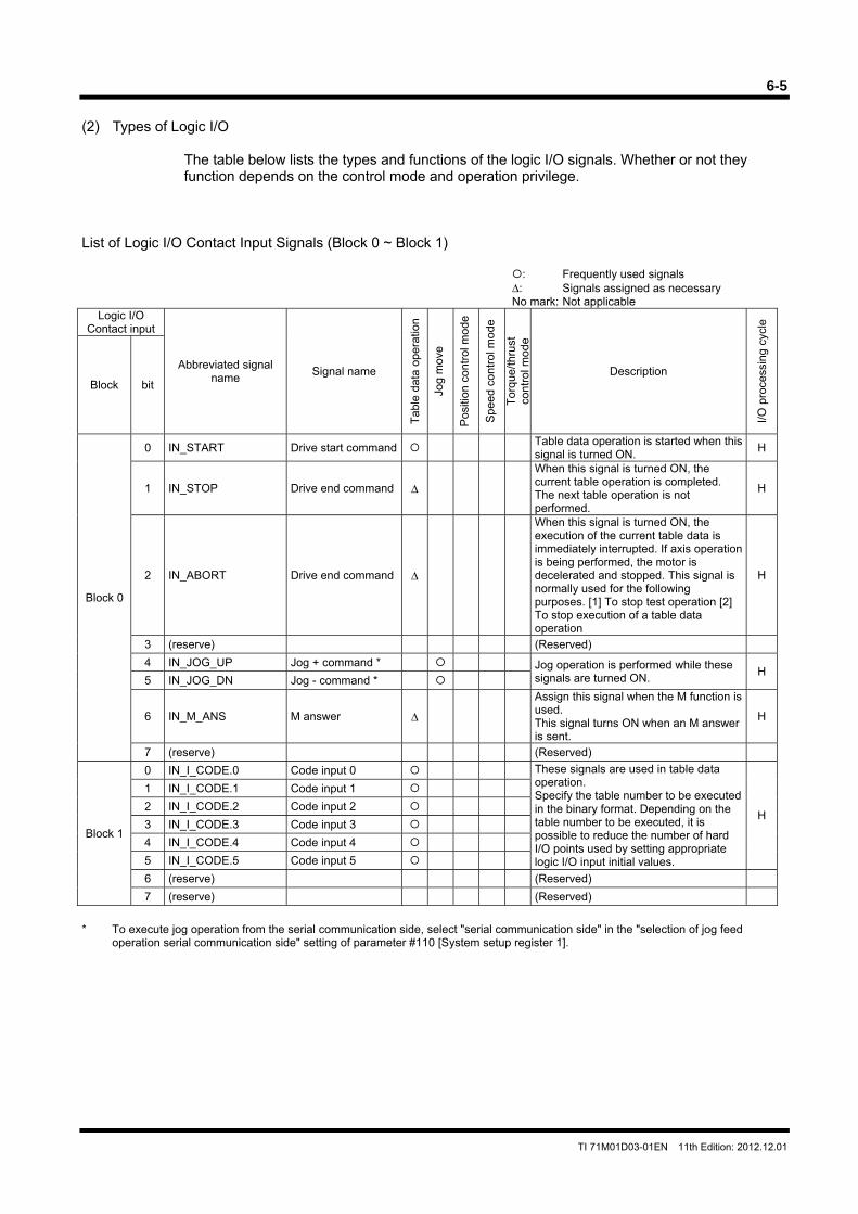
6-5
TI 71M01D03-01EN 11th Edition: 2012.12.01
(2) Types of Logic I/O
The table below lists the types and functions of the logic I/O signals. Whether or not they function depends on the control mode and operation privilege.
List of Logic I/O Contact Input Signals (Block 0 ~ Block 1)
: Frequently used signals Δ: Signals assigned as necessary No mark: Not applicable
Logic I/O Contact input
Abbreviated signal name
Signal name
Tab
le d
ata
oper
atio
n
Jog
mov
e
Pos
ition
con
trol
mod
e
Spe
ed c
ontr
ol m
ode
Tor
que/
thru
st
cont
rol m
ode
Description
I/O
pro
cess
ing
cycl
e
Block bit
Block 0
0 IN_START Drive start command Table data operation is started when this signal is turned ON.
H
1 IN_STOP Drive end command Δ
When this signal is turned ON, the current table operation is completed. The next table operation is not performed.
H
2 IN_ABORT Drive end command Δ
When this signal is turned ON, the execution of the current table data is immediately interrupted. If axis operation is being performed, the motor is decelerated and stopped. This signal is normally used for the following purposes. [1] To stop test operation [2] To stop execution of a table data operation
H
3 (reserve) (Reserved)
4 IN_JOG_UP Jog + command * Jog operation is performed while these signals are turned ON.
H5 IN_JOG_DN Jog - command *
6 IN_M_ANS M answer Δ
Assign this signal when the M function is used. This signal turns ON when an M answer is sent.
H
7 (reserve) (Reserved)
Block 1
0 IN_I_CODE.0 Code input 0 These signals are used in table data operation. Specify the table number to be executed in the binary format. Depending on the table number to be executed, it is possible to reduce the number of hard I/O points used by setting appropriate logic I/O input initial values.
H
1 IN_I_CODE.1 Code input 1
2 IN_I_CODE.2 Code input 2
3 IN_I_CODE.3 Code input 3
4 IN_I_CODE.4 Code input 4
5 IN_I_CODE.5 Code input 5
6 (reserve) (Reserved)
7 (reserve) (Reserved)
* To execute jog operation from the serial communication side, select "serial communication side" in the "selection of jog feed
operation serial communication side" setting of parameter #110 [System setup register 1].
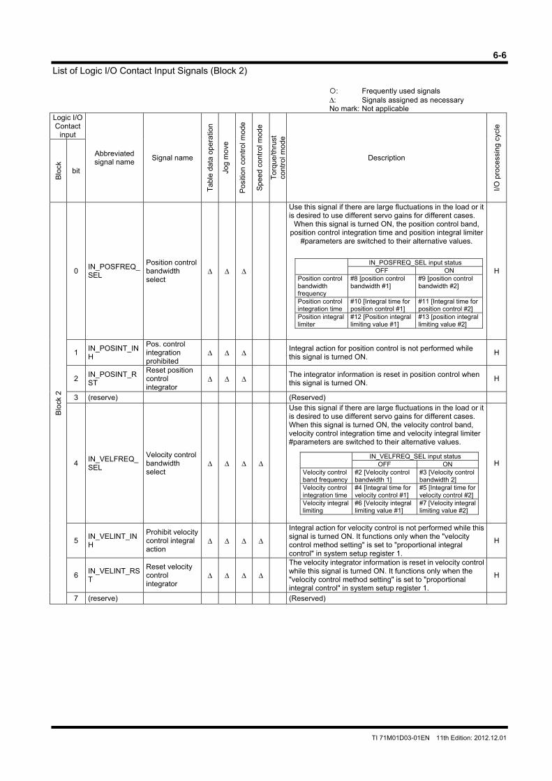
6-6
TI 71M01D03-01EN 11th Edition: 2012.12.01
List of Logic I/O Contact Input Signals (Block 2)
: Frequently used signals Δ: Signals assigned as necessary No mark: Not applicable
Logic I/O Contact
input
Abbreviated signal name
Signal name
Tab
le d
ata
oper
atio
n
Jog
mov
e
Pos
ition
con
trol
mod
e
Spe
ed c
ontr
ol m
ode
Tor
que/
thru
st
cont
rol m
ode
Description
I/O
pro
cess
ing
cycl
e
Blo
ck
bit
Blo
ck 2
0 IN_POSFREQ_SEL
Position control bandwidth select
Δ Δ Δ
Use this signal if there are large fluctuations in the load or it is desired to use different servo gains for different cases.
When this signal is turned ON, the position control band, position control integration time and position integral limiter
#parameters are switched to their alternative values.
H
1 IN_POSINT_INH
Pos. control integration prohibited
Δ Δ Δ Integral action for position control is not performed while this signal is turned ON.
H
2 IN_POSINT_RST
Reset position control integrator
Δ Δ Δ The integrator information is reset in position control when this signal is turned ON.
H
3 (reserve) (Reserved)
4 IN_VELFREQ_SEL
Velocity control bandwidth select
Δ Δ Δ Δ
Use this signal if there are large fluctuations in the load or it is desired to use different servo gains for different cases. When this signal is turned ON, the velocity control band, velocity control integration time and velocity integral limiter #parameters are switched to their alternative values.
H
5 IN_VELINT_INH
Prohibit velocity control integral action
Δ Δ Δ Δ
Integral action for velocity control is not performed while this signal is turned ON. It functions only when the "velocity control method setting" is set to "proportional integral control" in system setup register 1.
H
6 IN_VELINT_RST
Reset velocity control integrator
Δ Δ Δ Δ
The velocity integrator information is reset in velocity control while this signal is turned ON. It functions only when the "velocity control method setting" is set to "proportional integral control" in system setup register 1.
H
7 (reserve) (Reserved)
IN_VELFREQ_SEL input status OFF ON
Velocity control band frequency
#2 [Velocity control bandwidth 1]
#3 [Velocity control bandwidth 2]
Velocity control integration time
#4 [Integral time for velocity control #1]
#5 [Integral time for velocity control #2]
Velocity integral limiting
#6 [Velocity integral limiting value #1]
#7 [Velocity integral limiting value #2]
IN_POSFREQ_SEL input status OFF ON
Position control bandwidth frequency
#8 [position control bandwidth #1]
#9 [position control bandwidth #2]
Position control integration time
#10 [Integral time for position control #1]
#11 [Integral time for position control #2]
Position integral limiter
#12 [Position integral limiting value #1]
#13 [position integral limiting value #2]
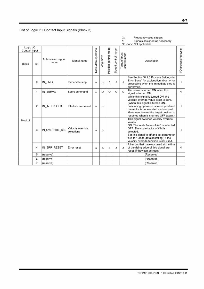
6-7
TI 71M01D03-01EN 11th Edition: 2012.12.01
List of Logic I/O Contact Input Signals (Block 3)
: Frequently used signals Δ: Signals assigned as necessary No mark: Not applicable
Logic I/O Contact input
Abbreviated signal name
Signal name
Tab
le d
ata
oper
atio
n
Jog
mov
e
Pos
ition
con
trol
mod
e
Spe
ed c
ontr
ol m
ode
Tor
que/
thru
st
cont
rol m
ode
Description
I/O
pro
cess
ing
cycl
e
Block bit
Block 3
0 IN_EMG Immediate stop Δ Δ Δ Δ Δ
See Section “6.1.5 Process Settings in Error State" for explanation about error processing when the immediate stop is performed.
H
1 IN_SERVO Servo command The servo is turned ON when this signal is turned ON.
H
2 IN_INTERLOCK Interlock command Δ Δ
While this signal is turned ON, the velocity override value is set to zero. (When this signal is turned ON, positioning operation is interrupted and the motor is decelerated and stopped. Movement toward the target position is resumed when it is turned OFF again.)
H
3 IN_OVERRIDE_SEL Velocity override selection Δ Δ
This signal switches velocity override values. ON: The scale factor of #45 is selected.OFF: The scale factor of #44 is selected. Set this signal to off and set parameter #44 to 10000 (default setting ) if the velocity override function is not used.
H
4 IN_ERR_RESET Error reset Δ Δ Δ Δ ΔAll errors that have occurred at the time of the rising edge of this signal are reset, if they can be reset.
H
5 (reserve) (Reserved)
6 (reserve) (Reserved)
7 (reserve) (Reserved)
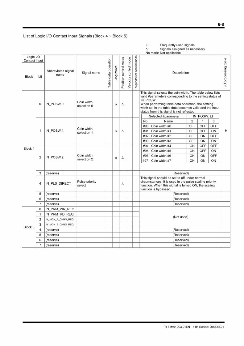
6-8
TI 71M01D03-01EN 11th Edition: 2012.12.01
List of Logic I/O Contact Input Signals (Block 4 ~ Block 5)
: Frequently used signals Δ: Signals assigned as necessary No mark: Not applicable
Logic I/O Contact input
Abbreviated signal name
Signal name
Tab
le d
ata
oper
atio
n
Jog
mov
e
Pos
ition
con
trol
mod
e
Vel
ocity
con
trol
mod
e
Tor
que/
thru
st c
ontr
ol m
ode
Description
I/O
pro
cess
ing
cycl
e
Block bit
Block 4
0 IN_POSW.0 Coin width selection 0 Δ Δ
This signal selects the coin width. The table below lists valid #parameters corresponding to the setting status of IN_POSW. When performing table data operation, the settling width set in the table data becomes valid and the input status from this signal is not reflected.
H1 IN_POSW.1 Coin width selection 1
Δ Δ
2 IN_POSW.2 Coin width selection 2
Δ Δ
3 (reserve) (Reserved)
4 IN_PLS_DIRECT Pulse priority select Δ
This signal should be set to off under normal circumstances. It is used in the pulse scaling priority function. When this signal is turned ON, the scaling function is bypassed.
5 (reserve) (Reserved)
6 (reserve) (Reserved)
7 (reserve) (Reserved)
Block 5
0 IN_PRM_WR_REQ
(Not used) 1 IN_PRM_RD_REQ
2 IN_MON_A_CHNG_REQ
3 IN_MON_B_CHNG_REQ
4 (reserve) (Reserved)
5 (reserve) (Reserved)
6 (reserve) (Reserved)
7 (reserve) (Reserved)
Selected #parameter IN_POSW.
No. Name 2 1 0
#90 Coin width #0 OFF OFF OFF
#91 Coin width #1 OFF OFF ON
#92 Coin width #2 OFF ON OFF
#93 Coin width #3 OFF ON ON
#94 Coin width #4 ON OFF OFF
#95 Coin width #5 ON OFF ON
#96 Coin width #6 ON ON OFF
#97 Coin width #7 ON ON ON
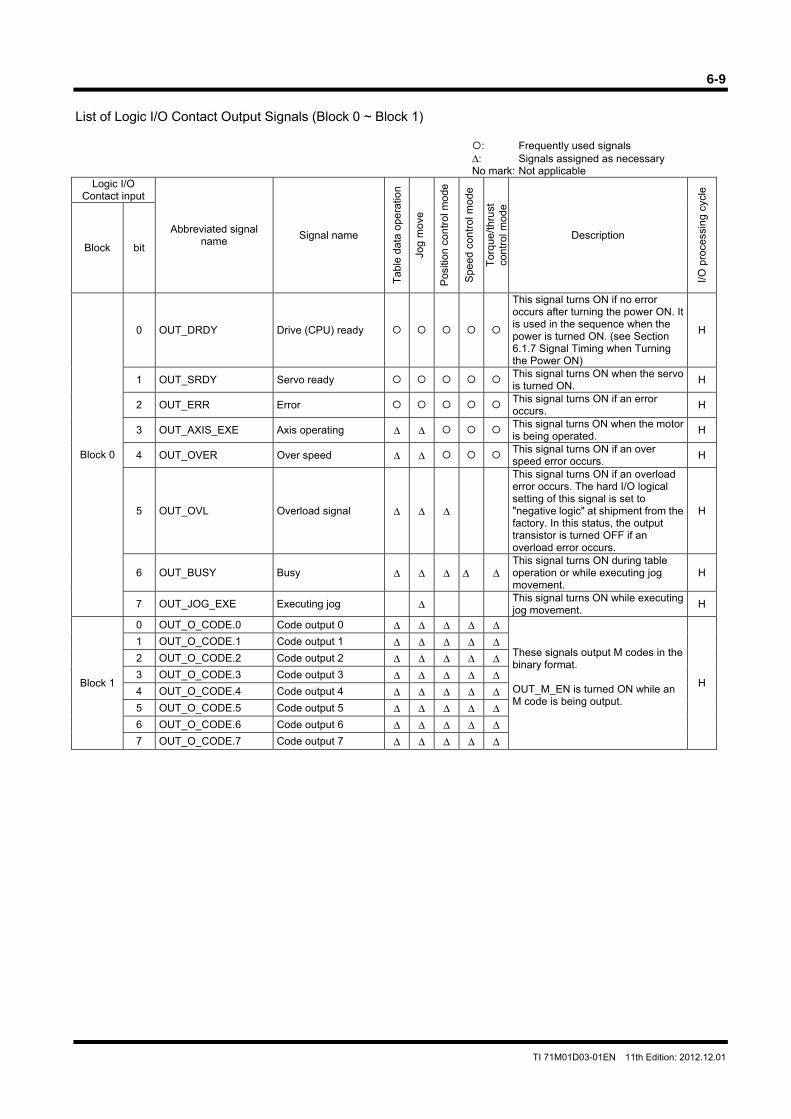
6-9
TI 71M01D03-01EN 11th Edition: 2012.12.01
List of Logic I/O Contact Output Signals (Block 0 ~ Block 1)
: Frequently used signals Δ: Signals assigned as necessary No mark: Not applicable
Logic I/O Contact input
Abbreviated signal name
Signal name
Tab
le d
ata
oper
atio
n
Jog
mov
e
Pos
ition
con
trol
mod
e
Spe
ed c
ontr
ol m
ode
Tor
que/
thru
st
cont
rol m
ode
Description
I/O
pro
cess
ing
cycl
e
Block bit
Block 0
0 OUT_DRDY Drive (CPU) ready
This signal turns ON if no error occurs after turning the power ON. It is used in the sequence when the power is turned ON. (see Section 6.1.7 Signal Timing when Turning the Power ON)
H
1 OUT_SRDY Servo ready This signal turns ON when the servo is turned ON.
H
2 OUT_ERR Error This signal turns ON if an error occurs.
H
3 OUT_AXIS_EXE Axis operating Δ Δ This signal turns ON when the motor is being operated.
H
4 OUT_OVER Over speed Δ Δ This signal turns ON if an over speed error occurs.
H
5 OUT_OVL Overload signal Δ Δ Δ
This signal turns ON if an overload error occurs. The hard I/O logical setting of this signal is set to "negative logic" at shipment from the factory. In this status, the output transistor is turned OFF if an overload error occurs.
H
6 OUT_BUSY Busy Δ Δ Δ Δ ΔThis signal turns ON during table operation or while executing jog movement.
H
7 OUT_JOG_EXE Executing jog Δ
This signal turns ON while executing jog movement.
H
Block 1
0 OUT_O_CODE.0 Code output 0 Δ Δ Δ Δ Δ
These signals output M codes in the binary format. OUT_M_EN is turned ON while an M code is being output.
H
1 OUT_O_CODE.1 Code output 1 Δ Δ Δ Δ Δ2 OUT_O_CODE.2 Code output 2 Δ Δ Δ Δ Δ3 OUT_O_CODE.3 Code output 3 Δ Δ Δ Δ Δ4 OUT_O_CODE.4 Code output 4 Δ Δ Δ Δ Δ5 OUT_O_CODE.5 Code output 5 Δ Δ Δ Δ Δ6 OUT_O_CODE.6 Code output 6 Δ Δ Δ Δ Δ7 OUT_O_CODE.7 Code output 7 Δ Δ Δ Δ Δ
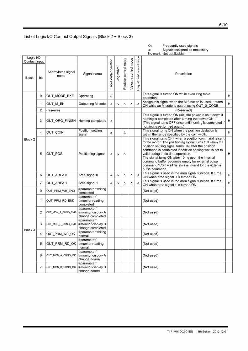
6-10
TI 71M01D03-01EN 11th Edition: 2012.12.01
List of Logic I/O Contact Output Signals (Block 2 ~ Block 3)
: Frequently used signals Δ: Signals assigned as necessary No mark: Not applicable
Logic I/O Contact input
Abbreviated signal name
Signal name
Tab
le d
ata
oper
atio
n
Jog
mov
e
Pos
ition
con
trol
mod
e
Vel
ocity
con
trol
mod
e
Tor
que/
thru
st c
ontr
ol m
ode
Description Block bit
Block 2
0 OUT_MODE_EXE Operating This signal is turned ON while executing table operation.
H
1 OUT_M_EN Outputting M code Δ Δ Δ Δ Δ Assign this signal when the M function is used. It turns ON while an M code is output using OUT_0_CODE.
H
2 (reserve) (Reserved)
3 OUT_ORG_FINISH Homing completed Δ
This signal is turned ON until the power is shut down if homing is completed after turning the power ON. (This signal turns OFF once until homing is completed if homing is performed again.)
H
4 OUT_COIN Position settling signal Δ Δ This signal turns ON when the position deviation is
within the range specified by the coin width. H
5 OUT_POS Positioning signal Δ Δ Δ
This signal turns OFF when a position command is sent to the motor. The positioning signal turns ON when the position settling signal turns ON after the position command is completed if position settling wait is set to valid during table data operation. The signal turns ON after 10ms upon the internal command buffer becomes empty for external pulse command “Coin wait ”is always invalid for the external pulse command.
H
6 OUT_AREA.0 Area signal 0 Δ Δ Δ Δ Δ This signal is used in the area signal function. It turns ON when area signal 0 is turned ON.
H
7 OUT_AREA.1 Area signal 1 Δ Δ Δ Δ Δ This signal is used in the area signal function. It turns ON when area signal 1 is turned ON.
H
Block 3
0 OUT_PRM_WR_END#parameter writing completed
(Not used)
1 OUT_PRM_RD_END#parameter/ #monitor reading completed
(Not used)
2 OUT_MON_A_CHNG_END
#parameter/ #monitor display A change completed
(Not used)
3 OUT_MON_B_CHNG_END
#parameter/ #monitor display B change completed
(Not used)
4 OUT_PRM_WR_OK#parameter writing normal
(Not used)
5 OUT_PRM_RD_OK#parameter/ #monitor reading normal
(Not used)
6 OUT_MON_A_CHNG_OK
#parameter/ #monitor display A change normal
(Not used)
7 OUT_MON_B_CHNG_OK
#parameter/ #monitor display B change normal
(Not used)
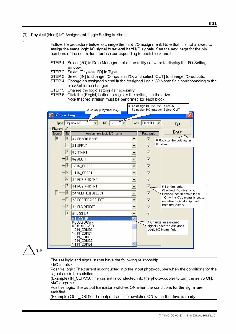
6-11
TI 71M01D03-01EN 11th Edition: 2012.12.01
(3) Physical (Hard) I/O Assignment, Logic Setting Method
Follow the procedure below to change the hard I/O assignment. Note that it is not allowed to assign the same logic I/O signal to several hard I/O signals. See the next page for the pin numbers of the controller interface corresponding to each block and bit. STEP 1 Select [I/O] in Data Management of the utility software to display the I/O Setting
window. STEP 2 Select [Physical I/O] in Type. STEP 3 Select [IN] to change I/O inputs in I/O, and select [OUT] to change I/O outputs. STEP 4 Change an assigned signal in the Assigned Logic I/O Name field corresponding to the
block/bit to be changed. STEP 5 Change the logic setting as necessary. STEP 6 Click the [Regist] button to register the settings in the drive.
Note that registration must be performed for each block.
The set logic and signal status have the following relationship. <I/O inputs> Positive logic: The current is conducted into the input photo-coupler when the conditions for the signal are to be satisfied. (Example) IN_SERVO: The current is conducted into the photo-coupler to turn the servo ON. <I/O outputs> Positive logic: The output transistor switches ON when the conditions for the signal are satisfied. (Example) OUT_DRDY: The output transistor switches ON when the drive is ready.
2 Select [Physical I/O].
3 To assign I/O inputs: Select IN To assign I/O outputs: Select OUT
6 Register the settings in the drive.
5 Set the logic. Checked: Positive logic Unchecked: Negative logic * Only the OVL signal is set to negative logic at shipment from the factory.
4 Change an assigned signal under the Assigned Logic I/O Name field.
TIP
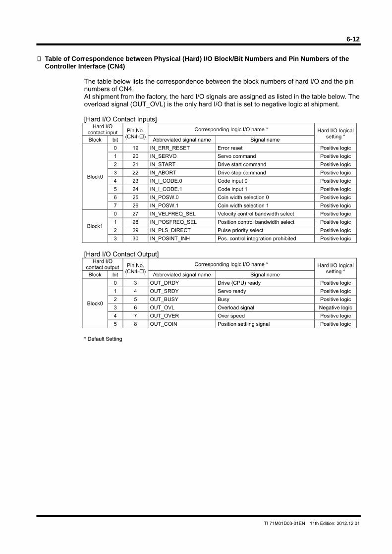
6-12
TI 71M01D03-01EN 11th Edition: 2012.12.01
Table of Correspondence between Physical (Hard) I/O Block/Bit Numbers and Pin Numbers of the
Controller Interface (CN4)
The table below lists the correspondence between the block numbers of hard I/O and the pin numbers of CN4. At shipment from the factory, the hard I/O signals are assigned as listed in the table below. The overload signal (OUT_OVL) is the only hard I/O that is set to negative logic at shipment. [Hard I/O Contact Inputs]
Hard I/O contact input Pin No.
(CN4-) Corresponding logic I/O name * Hard I/O logical
setting * Block bit Abbreviated signal name Signal name
Block0
0 19 IN_ERR_RESET Error reset Positive logic
1 20 IN_SERVO Servo command Positive logic
2 21 IN_START Drive start command Positive logic
3 22 IN_ABORT Drive stop command Positive logic
4 23 IN_I_CODE.0 Code input 0 Positive logic
5 24 IN_I_CODE.1 Code input 1 Positive logic
6 25 IN_POSW.0 Coin width selection 0 Positive logic
7 26 IN_POSW.1 Coin width selection 1 Positive logic
Block1
0 27 IN_VELFREQ_SEL Velocity control bandwidth select Positive logic
1 28 IN_POSFREQ_SEL Position control bandwidth select Positive logic
2 29 IN_PLS_DIRECT Pulse priority select Positive logic
3 30 IN_POSINT_INH Pos. control integration prohibited Positive logic
[Hard I/O Contact Output]
Hard I/O contact output Pin No.
(CN4-) Corresponding logic I/O name * Hard I/O logical
setting * Block bit Abbreviated signal name Signal name
Block0
0 3 OUT_DRDY Drive (CPU) ready Positive logic
1 4 OUT_SRDY Servo ready Positive logic
2 5 OUT_BUSY Busy Positive logic
3 6 OUT_OVL Overload signal Negative logic
4 7 OUT_OVER Over speed Positive logic
5 8 OUT_COIN Position settling signal Positive logic
* Default Setting
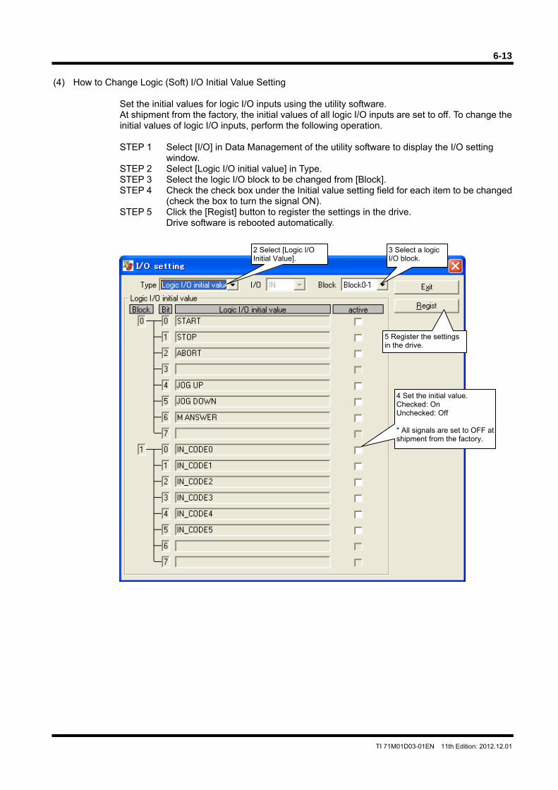
6-13
TI 71M01D03-01EN 11th Edition: 2012.12.01
(4) How to Change Logic (Soft) I/O Initial Value Setting
Set the initial values for logic I/O inputs using the utility software. At shipment from the factory, the initial values of all logic I/O inputs are set to off. To change the initial values of logic I/O inputs, perform the following operation. STEP 1 Select [I/O] in Data Management of the utility software to display the I/O setting
window. STEP 2 Select [Logic I/O initial value] in Type. STEP 3 Select the logic I/O block to be changed from [Block]. STEP 4 Check the check box under the Initial value setting field for each item to be changed
(check the box to turn the signal ON). STEP 5 Click the [Regist] button to register the settings in the drive.
Drive software is rebooted automatically.
2 Select [Logic I/O Initial Value].
3 Select a logic I/O block.
5 Register the settings in the drive.
4 Set the initial value. Checked: On Unchecked: Off * All signals are set to OFF at shipment from the factory.
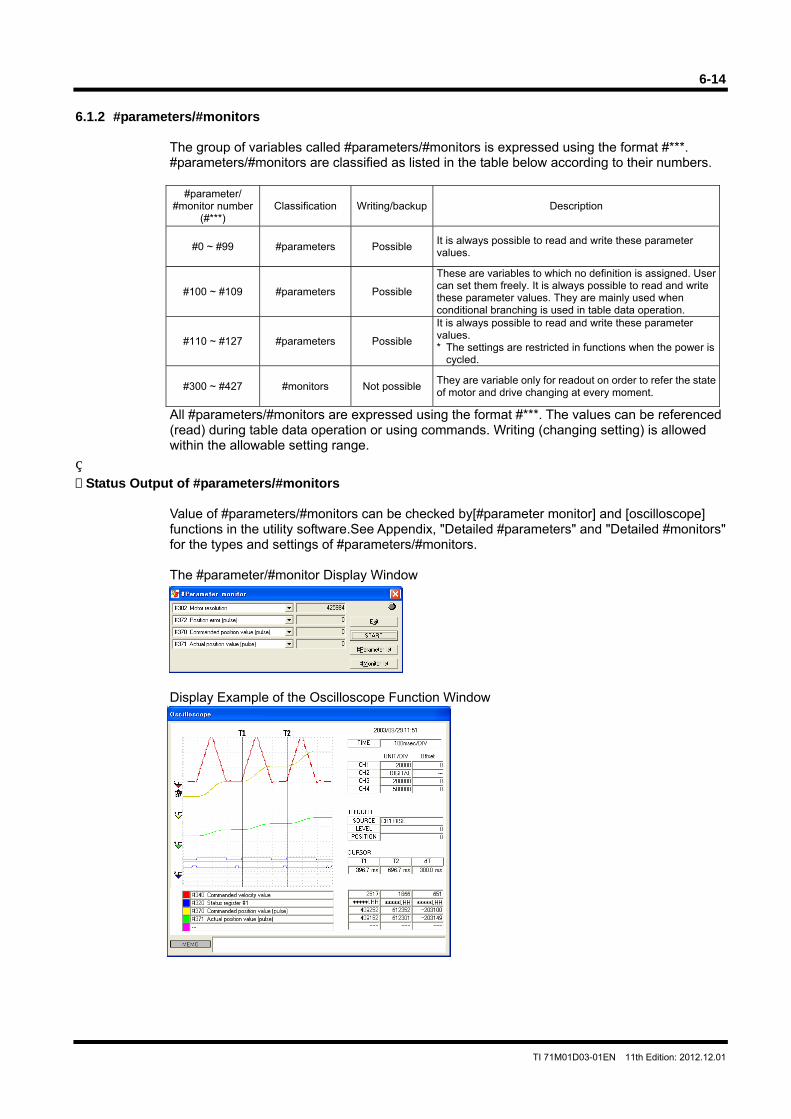
6-14
TI 71M01D03-01EN 11th Edition: 2012.12.01
6.1.2 #parameters/#monitors
The group of variables called #parameters/#monitors is expressed using the format #***. #parameters/#monitors are classified as listed in the table below according to their numbers.
#parameter/
#monitor number (#***)
Classification Writing/backup Description
#0 ~ #99 #parameters Possible It is always possible to read and write these parameter values.
#100 ~ #109 #parameters Possible
These are variables to which no definition is assigned. User can set them freely. It is always possible to read and write these parameter values. They are mainly used when conditional branching is used in table data operation.
#110 ~ #127 #parameters Possible
It is always possible to read and write these parameter values. * The settings are restricted in functions when the power is
cycled.
#300 ~ #427 #monitors Not possibleThey are variable only for readout on order to refer the state of motor and drive changing at every moment.
All #parameters/#monitors are expressed using the format #***. The values can be referenced (read) during table data operation or using commands. Writing (changing setting) is allowed within the allowable setting range.
Status Output of #parameters/#monitors
Value of #parameters/#monitors can be checked by[#parameter monitor] and [oscilloscope] functions in the utility software.See Appendix, "Detailed #parameters" and "Detailed #monitors" for the types and settings of #parameters/#monitors. The #parameter/#monitor Display Window
Display Example of the Oscilloscope Function Window
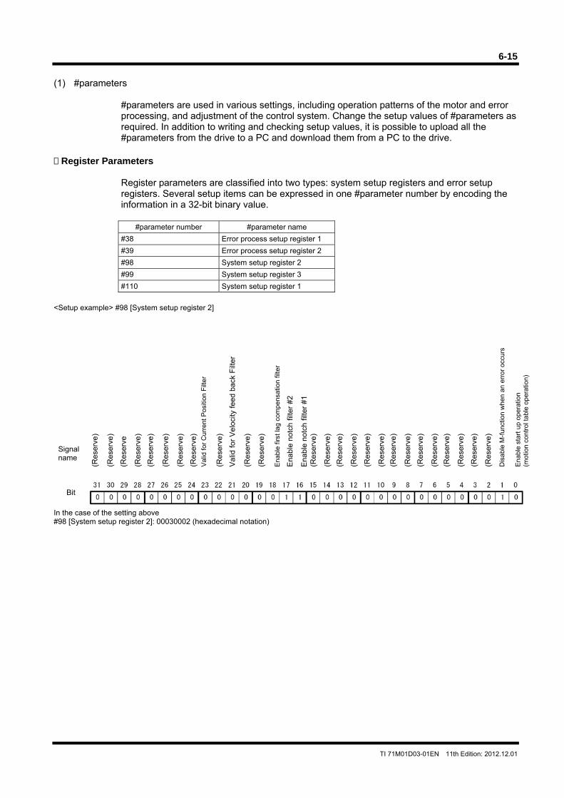
6-15
TI 71M01D03-01EN 11th Edition: 2012.12.01
(1) #parameters
#parameters are used in various settings, including operation patterns of the motor and error processing, and adjustment of the control system. Change the setup values of #parameters as required. In addition to writing and checking setup values, it is possible to upload all the #parameters from the drive to a PC and download them from a PC to the drive.
Register Parameters
Register parameters are classified into two types: system setup registers and error setup registers. Several setup items can be expressed in one #parameter number by encoding the information in a 32-bit binary value.
#parameter number #parameter name
#38 Error process setup register 1
#39 Error process setup register 2
#98 System setup register 2
#99 System setup register 3
#110 System setup register 1
<Setup example> #98 [System setup register 2] In the case of the setting above #98 [System setup register 2]: 00030002 (hexadecimal notation)
(Res
erve
)
Signalname
Ena
ble
star
t up
ope
ratio
n (m
otio
n co
ntro
l tab
le o
pera
tion)
Dis
able
M-f
unct
ion
whe
n an
err
or o
ccur
s
Ena
ble
notc
h fil
ter
#1
Ena
ble
notc
h fil
ter
#2
Ena
ble
first
lag
com
pens
atio
n fil
ter
Val
id fo
r V
eloc
ity fe
ed b
ack
Filt
er
Val
id fo
r C
urre
nt P
ositi
on F
ilte
r
(Res
erve
)
Bit
(Res
erve
)
(Res
erve
(Res
erve
) (R
eser
ve)
(Res
erve
) (R
eser
ve)
(Res
erve
)
(Res
erve
) (R
eser
ve)
(Res
erve
)
(Res
erve
)
(Res
erve
) (R
eser
ve)
(Res
erve
) (R
eser
ve)
(Res
erve
) (R
eser
ve)
(Res
erve
)
(Res
erve
)
(Res
erve
)
(Res
erve
)
(Res
erve
)
(Res
erve
)
6-16
TI 71M01D03-01EN 11th Edition: 2012.12.01
How to Write to #parameters
Values can be written to #parameters using one of the following three methods.
Method 1: Changing values in the #parameter window of the utility software This method is mainly used at startup. This method is the easiest to use, as setup windows are provided, allowing direct access to each item.
Method 2: Changing values in the terminal window of the utility software. This method is mainly used at startup. Enter the setup values of #parameters directly.
Method 3: Changing values by a table data operation In this method, values of #parameters are changed by executing the table data operation prepared by the controller instrument in advance. See Section 6.4.9, "Parameter Change" for the detailed information.
Changing values of #parameters can refer to both "saving" and "registration." These two concepts are different in the following way. Saving: This means changing #parameter values in RAM. Changed data returns to
the status it had before changing once the power is turned OFF. Use this method when you want to change #parameter values temporarily.
Registration: This means changing #parameter values in both the EEPROM and RAM. The changed settings are maintained even if the power is turned OFF. Use this method to commit the settings. Note that "registration" is not accepted while the motor is operating. Perform registration while the motor is stopped
* The drive loads the #parameters from the EEPROM into RAM once at startup. Afterward, the drive operates based on the #parameter settings in RAM.
When #parameters are registered, their values are written in the EEPROM. There is a limit on the allowable number of times the EEPROM can be written to (approximately 1 million times). If this limit was exceeded, the EEPROM may be damaged and the drive may not start up. If you select "specify registration" for #parameters in the #parameter change function during table operation, this limit may be exceeded depending on the pattern used.
TIP
CAUTION
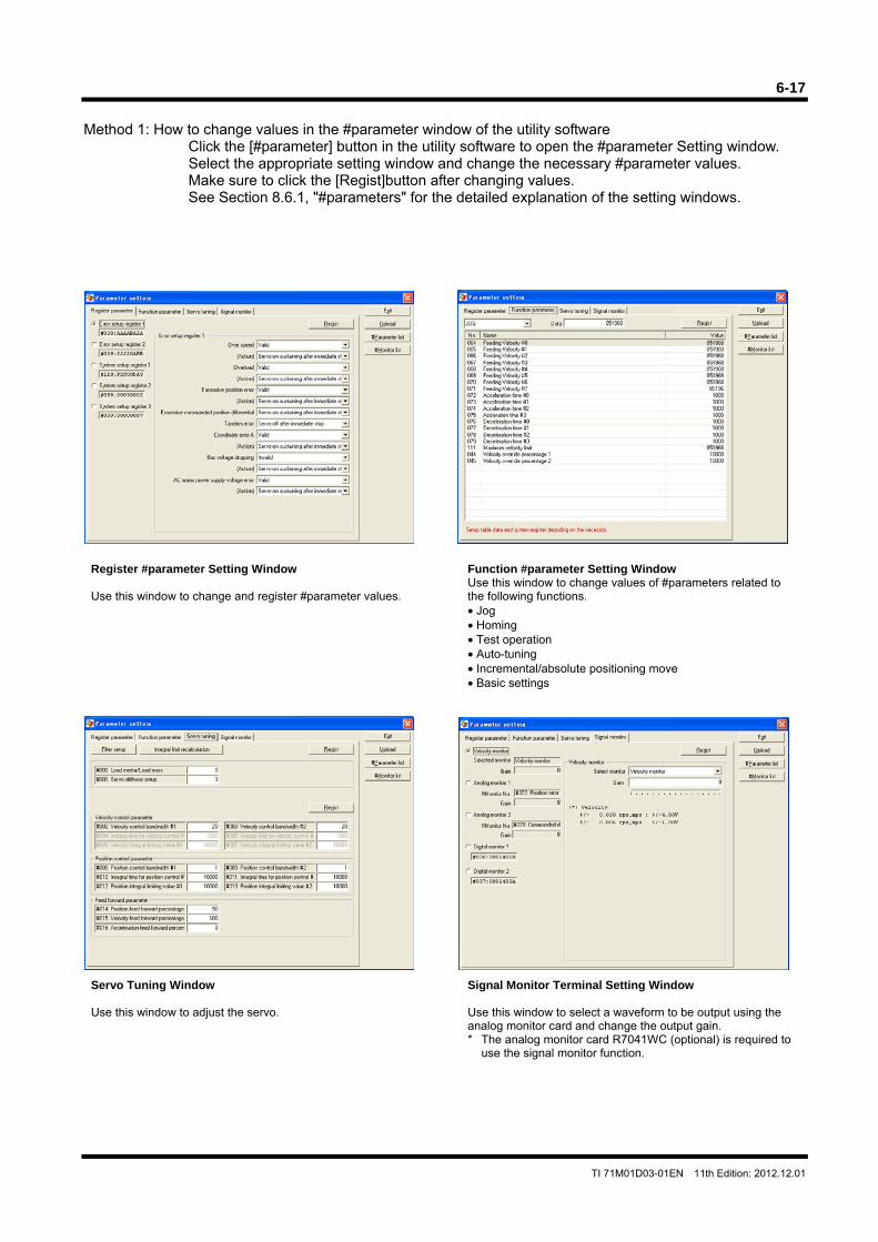
6-17
TI 71M01D03-01EN 11th Edition: 2012.12.01
Method 1: How to change values in the #parameter window of the utility software
Click the [#parameter] button in the utility software to open the #parameter Setting window. Select the appropriate setting window and change the necessary #parameter values. Make sure to click the [Regist]button after changing values. See Section 8.6.1, "#parameters" for the detailed explanation of the setting windows.
Register #parameter Setting Window Use this window to change and register #parameter values.
Function #parameter Setting Window Use this window to change values of #parameters related to the following functions. • Jog • Homing • Test operation • Auto-tuning • Incremental/absolute positioning move • Basic settings
Servo Tuning Window Use this window to adjust the servo.
Signal Monitor Terminal Setting Window Use this window to select a waveform to be output using the analog monitor card and change the output gain. * The analog monitor card R7041WC (optional) is required to
use the signal monitor function.
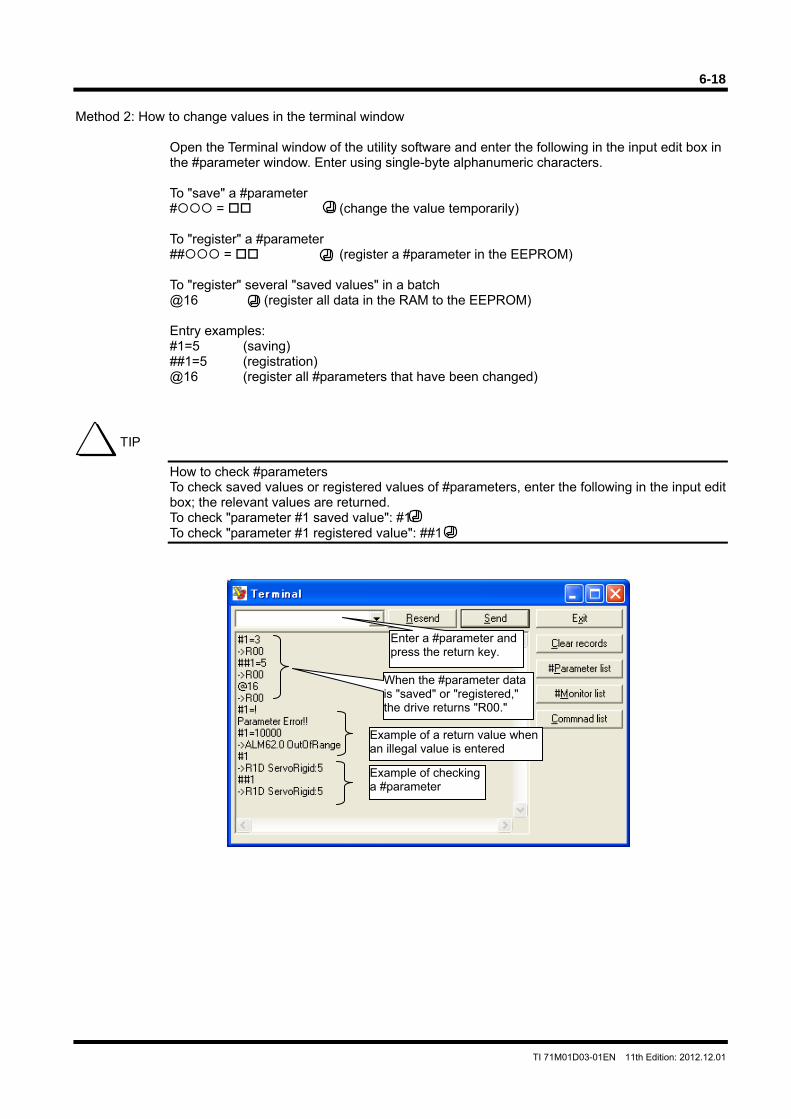
6-18
TI 71M01D03-01EN 11th Edition: 2012.12.01
Method 2: How to change values in the terminal window
Open the Terminal window of the utility software and enter the following in the input edit box in the #parameter window. Enter using single-byte alphanumeric characters. To "save" a #parameter # = (change the value temporarily) To "register" a #parameter ## = (register a #parameter in the EEPROM) To "register" several "saved values" in a batch @16 (register all data in the RAM to the EEPROM) Entry examples: #1=5 (saving) ##1=5 (registration) @16 (register all #parameters that have been changed)
How to check #parameters To check saved values or registered values of #parameters, enter the following in the input edit box; the relevant values are returned. To check "parameter #1 saved value": #1 To check "parameter #1 registered value": ##1
TIP
When the #parameter data is "saved" or "registered," the drive returns "R00."
Enter a #parameter and press the return key.
Example of a return value when an illegal value is entered
Example of checking a #parameter

6-19
TI 71M01D03-01EN 11th Edition: 2012.12.01
Method 3: How to change values by a table data operation
See Section 6.4.9, "Parameter Change." How to Back up #parameters
See the item in Section 8.7.4, "Backup."
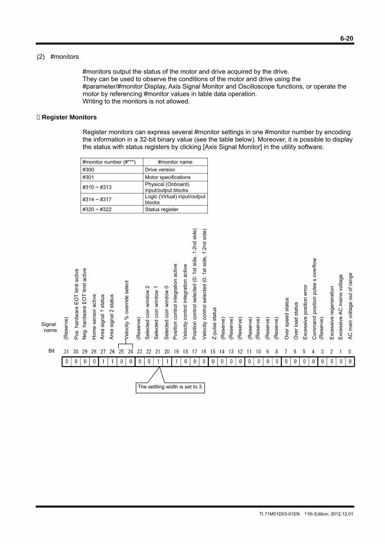
6-20
TI 71M01D03-01EN 11th Edition: 2012.12.01
(2) #monitors
#monitors output the status of the motor and drive acquired by the drive. They can be used to observe the conditions of the motor and drive using the #parameter/#monitor Display, Axis Signal Monitor and Oscilloscope functions, or operate the motor by referencing #monitor values in table data operation. Writing to the monitors is not allowed.
Register Monitors
Register monitors can express several #monitor settings in one #monitor number by encoding the information in a 32-bit binary value (see the table below). Moreover, it is possible to display the status with status registers by clicking [Axis Signal Monitor] in the utility software.
#monitor number (#***) #monitor name
#300 Drive version
#301 Motor specifications
#310 ~ #313 Physical (Onboard) input/output blocks
#314 ~ #317 Logic (Virtual) input/output blocks
#320 ~ #322 Status register
Bit
(Res
erve
)
(Res
erve
)
Signal name
Com
man
d po
sitio
n pu
lse
s ov
erflo
w
Exc
essi
ve p
ositi
on e
rro
r
Ove
r lo
ad s
tatu
s
Ove
r sp
eed
stat
us
AC
mai
n vo
ltage
out
of r
ang
e
Exc
essi
ve A
C m
ains
vol
tage
Pos
. har
dwa
re E
OT
lim
it ac
tive
Hom
e se
nsor
act
ive
Neg
. har
dwar
e E
OT
lim
it ac
tive
Are
a si
gnal
2 s
tatu
s
Are
a si
gnal
1 s
tatu
s
Vel
ocity
% o
verr
ide
sele
ct
Exc
essi
ve r
egen
erat
ion
Z-p
ulse
sta
tus
(Res
erve
)
(Res
erve
) (R
eser
ve)
(Res
erve
)
(Res
erve
)
(Res
erve
) (R
eser
ve)
(Res
erve
)
Pos
ition
con
trol
sel
ecte
d (0
: 1st
sid
e, 1
:2nd
sid
e)
Vel
ocity
con
trol
sel
ecte
d (0
: 1st
sid
e, 1
:2nd
sid
e)
Vel
ocity
con
trol
inte
grat
ion
activ
e
Pos
ition
con
trol
inte
grat
ion
activ
e
Sel
ecte
d co
in w
indo
w 0
Sel
ecte
d co
in w
indo
w 1
Sel
ecte
d co
in w
indo
w 2
The settling width is set to 3.
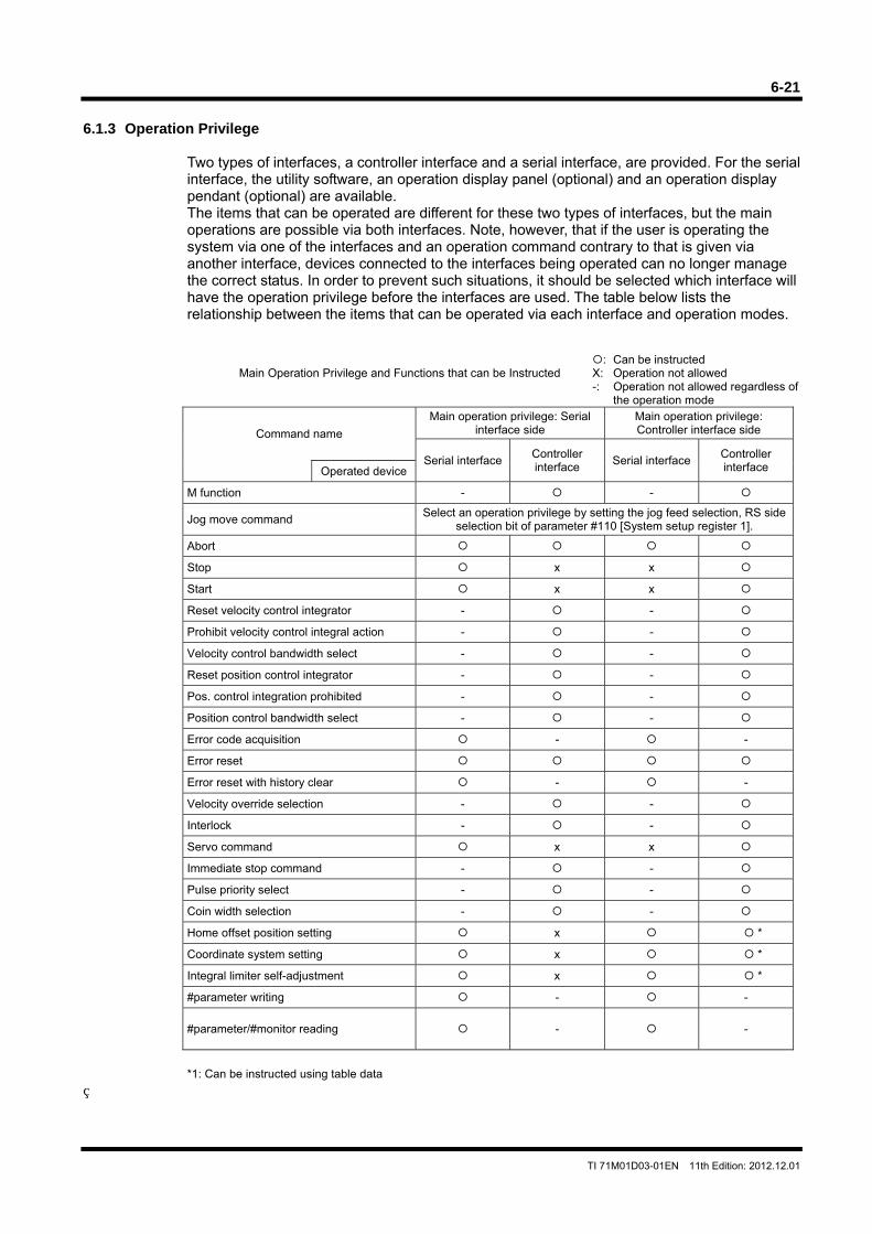
6-21
TI 71M01D03-01EN 11th Edition: 2012.12.01
6.1.3 Operation Privilege
Two types of interfaces, a controller interface and a serial interface, are provided. For the serial interface, the utility software, an operation display panel (optional) and an operation display pendant (optional) are available. The items that can be operated are different for these two types of interfaces, but the main operations are possible via both interfaces. Note, however, that if the user is operating the system via one of the interfaces and an operation command contrary to that is given via another interface, devices connected to the interfaces being operated can no longer manage the correct status. In order to prevent such situations, it should be selected which interface will have the operation privilege before the interfaces are used. The table below lists the relationship between the items that can be operated via each interface and operation modes.
: Can be instructed Main Operation Privilege and Functions that can be Instructed X: Operation not allowed
-: Operation not allowed regardless of the operation mode
Command name
Main operation privilege: Serial interface side
Main operation privilege: Controller interface side
Serial interfaceController interface
Serial interface Controller interface Operated device
M function - -
Jog move command Select an operation privilege by setting the jog feed selection, RS side
selection bit of parameter #110 [System setup register 1].
Abort
Stop x x
Start x x
Reset velocity control integrator - -
Prohibit velocity control integral action - -
Velocity control bandwidth select - -
Reset position control integrator - -
Pos. control integration prohibited - -
Position control bandwidth select - -
Error code acquisition - -
Error reset
Error reset with history clear - -
Velocity override selection - -
Interlock - -
Servo command x x
Immediate stop command - -
Pulse priority select - -
Coin width selection - -
Home offset position setting x *
Coordinate system setting x *
Integral limiter self-adjustment x *
#parameter writing - -
#parameter/#monitor reading - -
*1: Can be instructed using table data
6-22
TI 71M01D03-01EN 11th Edition: 2012.12.01
(1) How to Select Operation Privilege
The main operation privilege is always set to the controller interface when the power is turned ON.
[1] There are three ways to switch the main operation privilege from the controller interface
side to the serial communication side. Method 1: It can be switched when opening the Operation window in the utility software. Method 2: It can be switched by the switch button in the Operation window. Method 3: It can be switched by issuing the command @5:0 from the terminal window.
[2] There are two ways to switch the operation privilege from the RS communication side to
the controller interface side. Method 1: It can be switched by the switch button in the Operation window in the utility
software. Method 2: It can be switched by issuing the command @5:1 from the terminal window.
When opening the Operation window from the utility software, a message box asking whether or not to select the serial communication side appears if the main operation privilege is on the controller side. Note that the main operation privilege is not returned to the original setting automatically when the Operation window is closed. Make sure to switch the privilege back to the controller interface if it is necessary to continue operating the system via the controller interface.
CAUTION
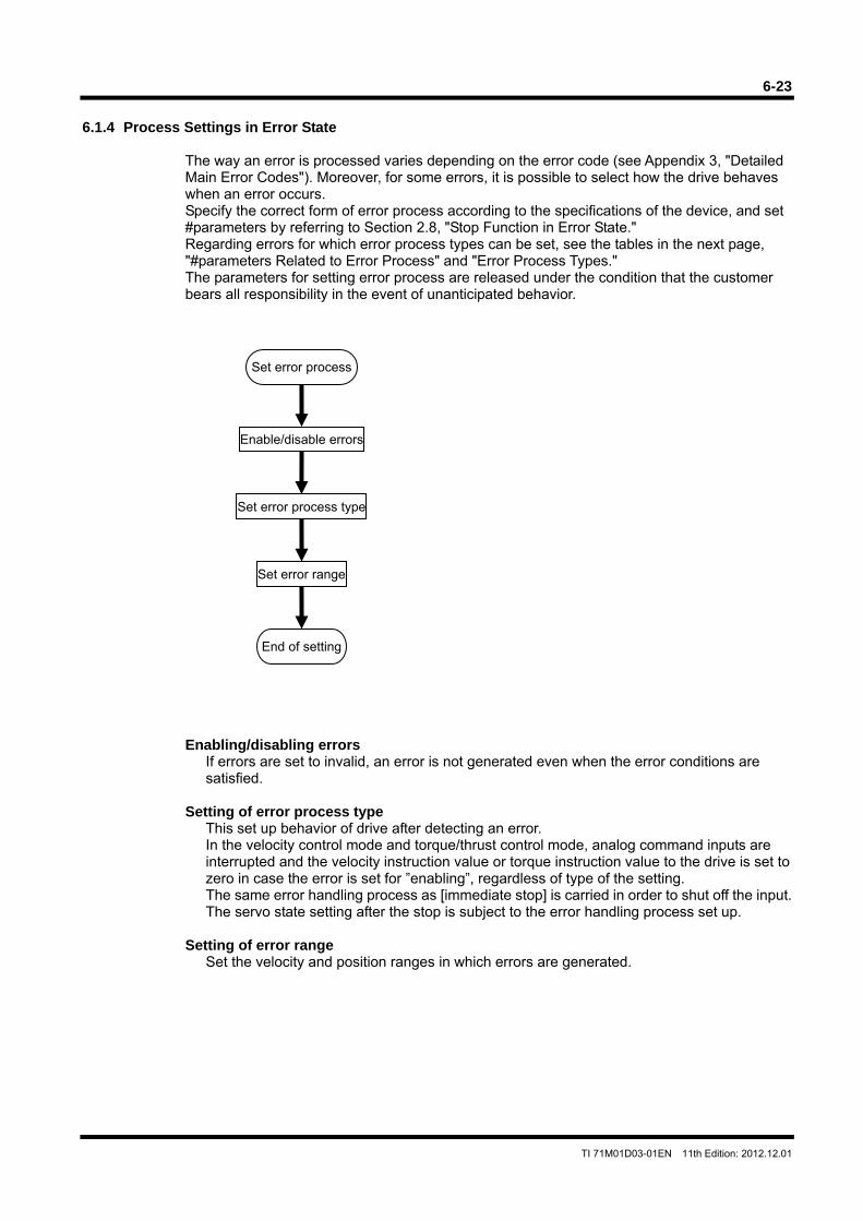
6-23
TI 71M01D03-01EN 11th Edition: 2012.12.01
6.1.4 Process Settings in Error State
The way an error is processed varies depending on the error code (see Appendix 3, "Detailed Main Error Codes"). Moreover, for some errors, it is possible to select how the drive behaves when an error occurs. Specify the correct form of error process according to the specifications of the device, and set #parameters by referring to Section 2.8, "Stop Function in Error State." Regarding errors for which error process types can be set, see the tables in the next page, "#parameters Related to Error Process" and "Error Process Types." The parameters for setting error process are released under the condition that the customer bears all responsibility in the event of unanticipated behavior.
Enabling/disabling errors If errors are set to invalid, an error is not generated even when the error conditions are satisfied.
Setting of error process type
This set up behavior of drive after detecting an error. In the velocity control mode and torque/thrust control mode, analog command inputs are interrupted and the velocity instruction value or torque instruction value to the drive is set to zero in case the error is set for ”enabling”, regardless of type of the setting. The same error handling process as [immediate stop] is carried in order to shut off the input. The servo state setting after the stop is subject to the error handling process set up.
Setting of error range
Set the velocity and position ranges in which errors are generated.
Set error process
Enable/disable errors
Set error process type
Set error range
End of setting
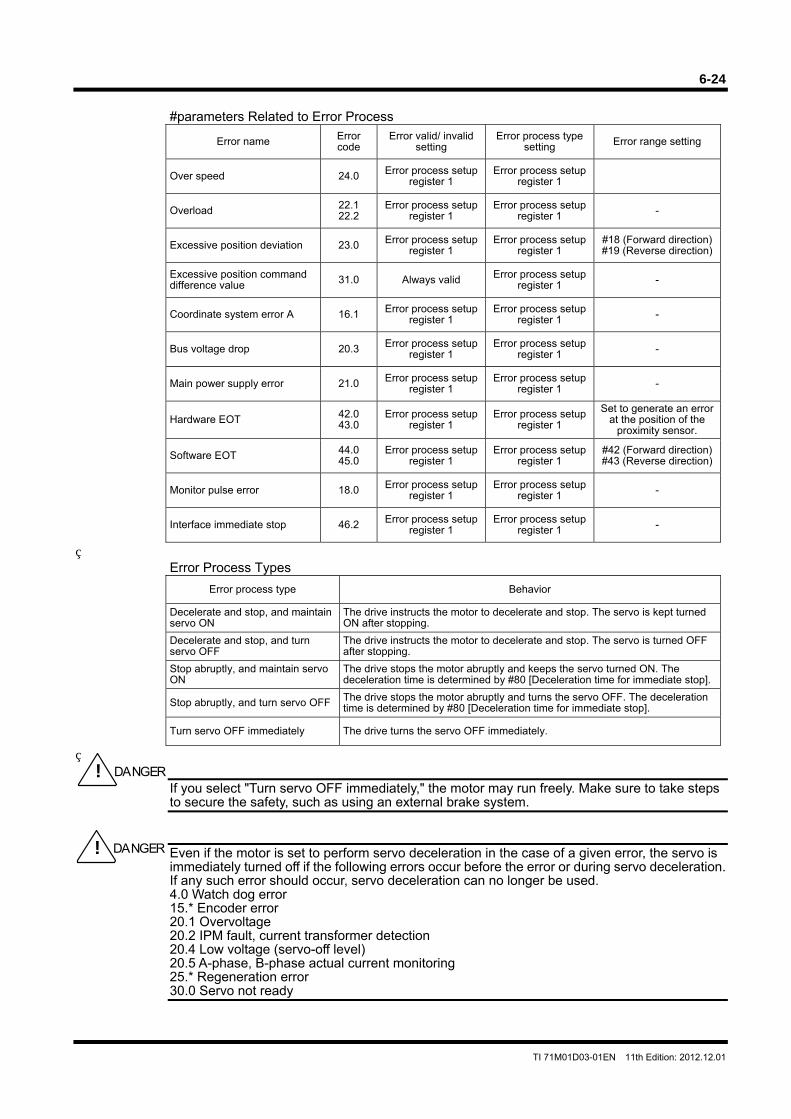
6-24
TI 71M01D03-01EN 11th Edition: 2012.12.01
#parameters Related to Error Process
Error name Error code
Error valid/ invalid setting
Error process type setting Error range setting
Over speed 24.0 Error process setup register 1
Error process setup register 1
Overload 22.1 22.2
Error process setup register 1
Error process setup register 1 -
Excessive position deviation 23.0 Error process setup register 1
Error process setup register 1
#18 (Forward direction)#19 (Reverse direction)
Excessive position command difference value 31.0 Always valid Error process setup
register 1 -
Coordinate system error A 16.1 Error process setup register 1
Error process setup register 1 -
Bus voltage drop 20.3 Error process setup register 1
Error process setup register 1 -
Main power supply error 21.0 Error process setup register 1
Error process setup register 1 -
Hardware EOT 42.0 43.0
Error process setup register 1
Error process setup register 1
Set to generate an error at the position of the
proximity sensor.
Software EOT 44.0 45.0
Error process setup register 1
Error process setup register 1
#42 (Forward direction)#43 (Reverse direction)
Monitor pulse error 18.0 Error process setup register 1
Error process setup register 1 -
Interface immediate stop 46.2 Error process setup register 1
Error process setup register 1 -
Error Process Types
Error process type Behavior
Decelerate and stop, and maintain servo ON
The drive instructs the motor to decelerate and stop. The servo is kept turned ON after stopping.
Decelerate and stop, and turn servo OFF
The drive instructs the motor to decelerate and stop. The servo is turned OFF after stopping.
Stop abruptly, and maintain servo ON
The drive stops the motor abruptly and keeps the servo turned ON. The deceleration time is determined by #80 [Deceleration time for immediate stop].
Stop abruptly, and turn servo OFF The drive stops the motor abruptly and turns the servo OFF. The deceleration time is determined by #80 [Deceleration time for immediate stop].
Turn servo OFF immediately The drive turns the servo OFF immediately.
If you select "Turn servo OFF immediately," the motor may run freely. Make sure to take steps to secure the safety, such as using an external brake system.
Even if the motor is set to perform servo deceleration in the case of a given error, the servo is immediately turned off if the following errors occur before the error or during servo deceleration. If any such error should occur, servo deceleration can no longer be used. 4.0 Watch dog error 15.* Encoder error 20.1 Overvoltage 20.2 IPM fault, current transformer detection 20.4 Low voltage (servo-off level) 20.5 A-phase, B-phase actual current monitoring 25.* Regeneration error 30.0 Servo not ready
! DANGER
! DANGER
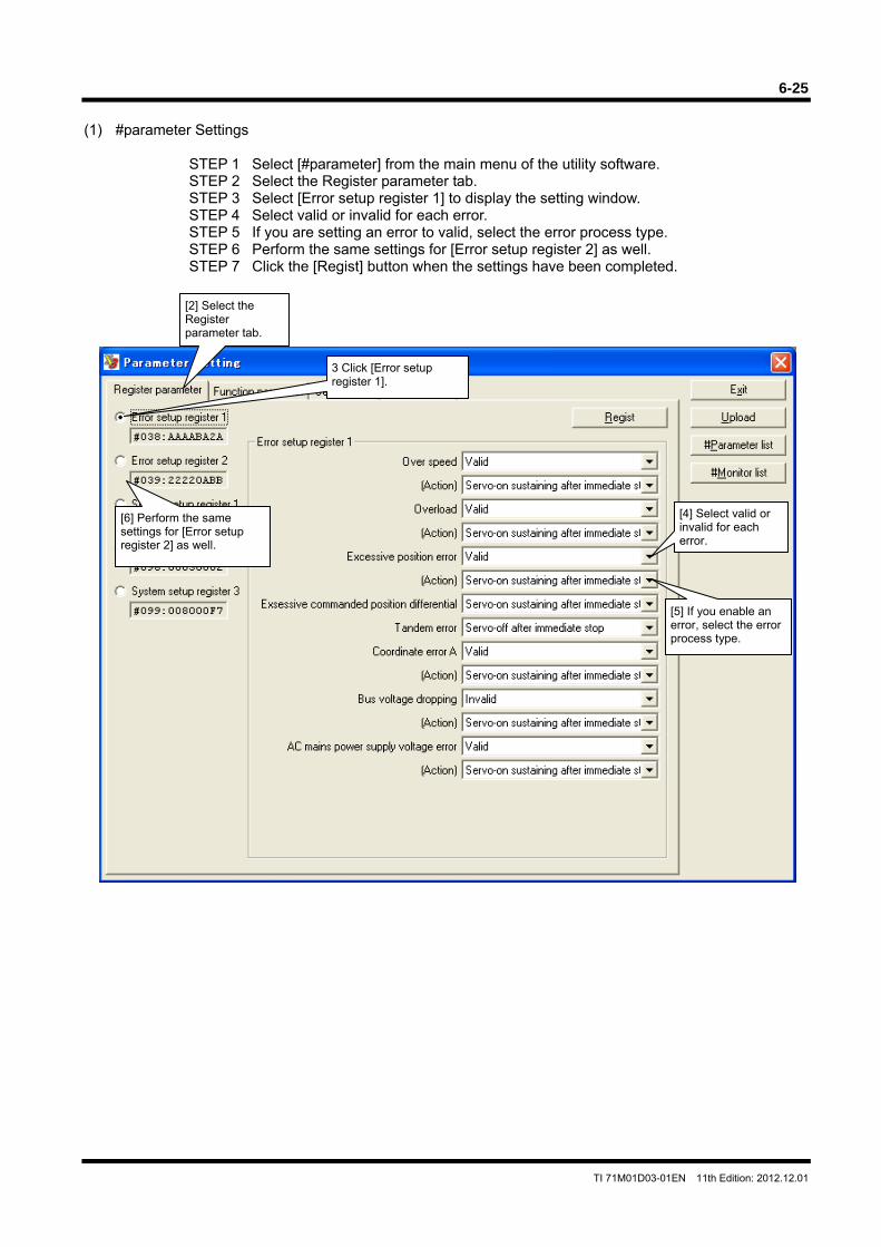
6-25
TI 71M01D03-01EN 11th Edition: 2012.12.01
(1) #parameter Settings
STEP 1 Select [#parameter] from the main menu of the utility software. STEP 2 Select the Register parameter tab. STEP 3 Select [Error setup register 1] to display the setting window. STEP 4 Select valid or invalid for each error. STEP 5 If you are setting an error to valid, select the error process type. STEP 6 Perform the same settings for [Error setup register 2] as well. STEP 7 Click the [Regist] button when the settings have been completed.
[6] Perform the same settings for [Error setup register 2] as well.
[4] Select valid or invalid for each error.
[5] If you enable an error, select the error process type.
[2] Select the Register parameter tab.
3 Click [Error setup register 1].
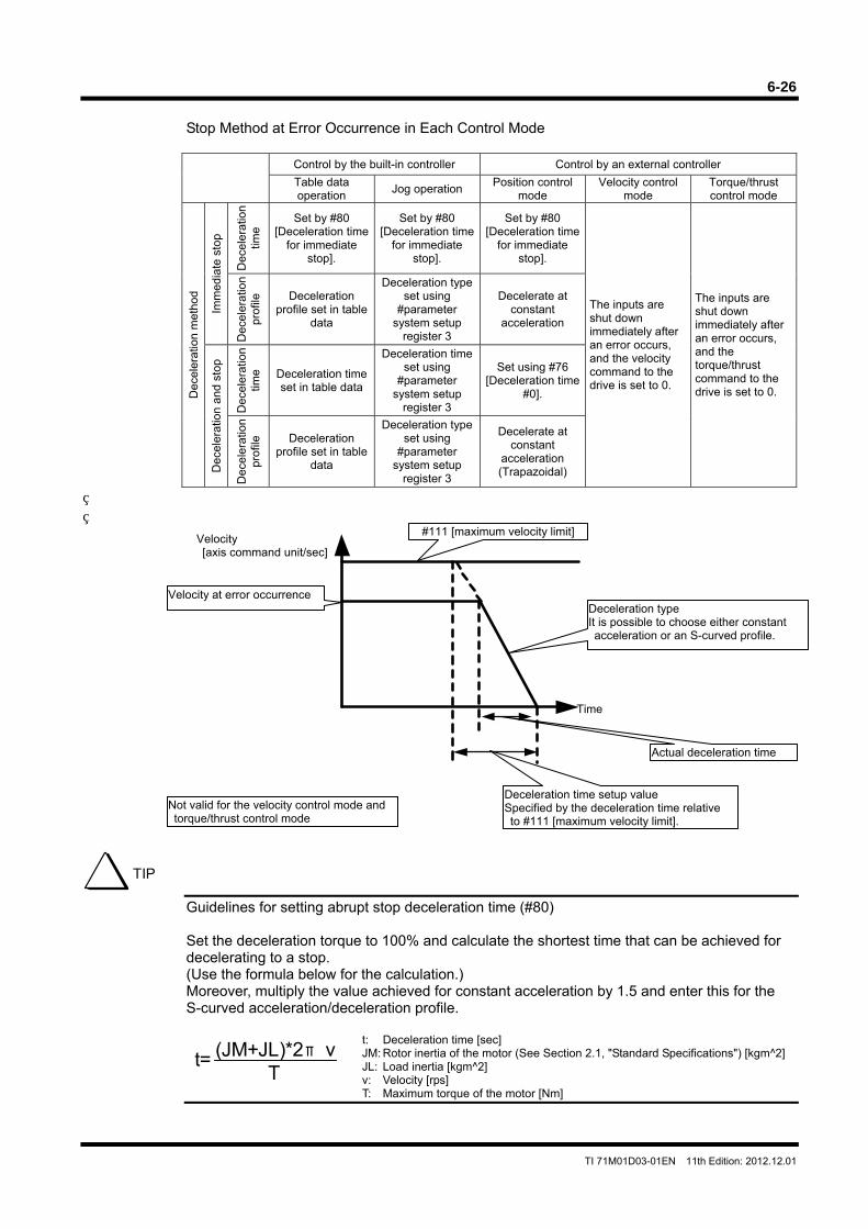
6-26
TI 71M01D03-01EN 11th Edition: 2012.12.01
Stop Method at Error Occurrence in Each Control Mode
Control by the built-in controller Control by an external controller
Table data operation
Jog operation Position control
mode Velocity control
mode Torque/thrust control mode
Dec
eler
atio
n m
etho
d
Imm
edia
te s
top
Dec
eler
atio
n tim
e
Set by #80 [Deceleration time
for immediate stop].
Set by #80 [Deceleration time
for immediate stop].
Set by #80 [Deceleration time
for immediate stop].
The inputs are shut down immediately after an error occurs, and the velocity command to the drive is set to 0.
The inputs are shut down immediately after an error occurs, and the torque/thrust command to the drive is set to 0.
Dec
eler
atio
n pr
ofile
Deceleration profile set in table
data
Deceleration type set using
#parameter system setup
register 3
Decelerate at constant
acceleration
Dec
eler
atio
n an
d s
top
Dec
eler
atio
n tim
e Deceleration time set in table data
Deceleration time set using
#parameter system setup
register 3
Set using #76 [Deceleration time
#0].
Dec
eler
atio
n pr
ofile
Deceleration profile set in table
data
Deceleration type set using
#parameter system setup
register 3
Decelerate at constant
acceleration (Trapazoidal)
Guidelines for setting abrupt stop deceleration time (#80) Set the deceleration torque to 100% and calculate the shortest time that can be achieved for decelerating to a stop. (Use the formula below for the calculation.) Moreover, multiply the value achieved for constant acceleration by 1.5 and enter this for the S-curved acceleration/deceleration profile. t: Deceleration time [sec] JM: Rotor inertia of the motor (See Section 2.1, "Standard Specifications") [kgm^2] JL: Load inertia [kgm^2] v: Velocity [rps] T: Maximum torque of the motor [Nm]
TIP
(JM+JL)*2πvT
t=
Velocity [axis command unit/sec]
Time
Velocity at error occurrence
#111 [maximum velocity limit]
Deceleration type It is possible to choose either constant acceleration or an S-curved profile.
Deceleration time setup value Specified by the deceleration time relative to #111 [maximum velocity limit].
Actual deceleration time
Not valid for the velocity control mode and torque/thrust control mode
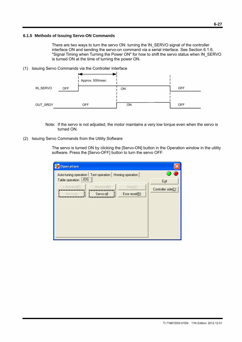
6-27
TI 71M01D03-01EN 11th Edition: 2012.12.01
6.1.5 Methods of Issuing Servo-ON Commands
There are two ways to turn the servo ON: turning the IN_SERVO signal of the controller interface ON and sending the servo-on command via a serial interface. See Section 6.1.6, "Signal Timing when Turning the Power ON" for how to shift the servo status when IN_SERVO is turned ON at the time of turning the power ON.
(1) Issuing Servo Commands via the Controller Interface
Note: If the servo is not adjusted, the motor maintains a very low torque even when the servo is turned ON.
(2) Issuing Servo Commands from the Utility Software
The servo is turned ON by clicking the [Servo-ON] button in the Operation window in the utility software. Press the [Servo-OFF] button to turn the servo OFF.
IN_SERVO
ON
OFF
OUT_SRDY OFF
Approx. 500msec
ON OFF
OFF
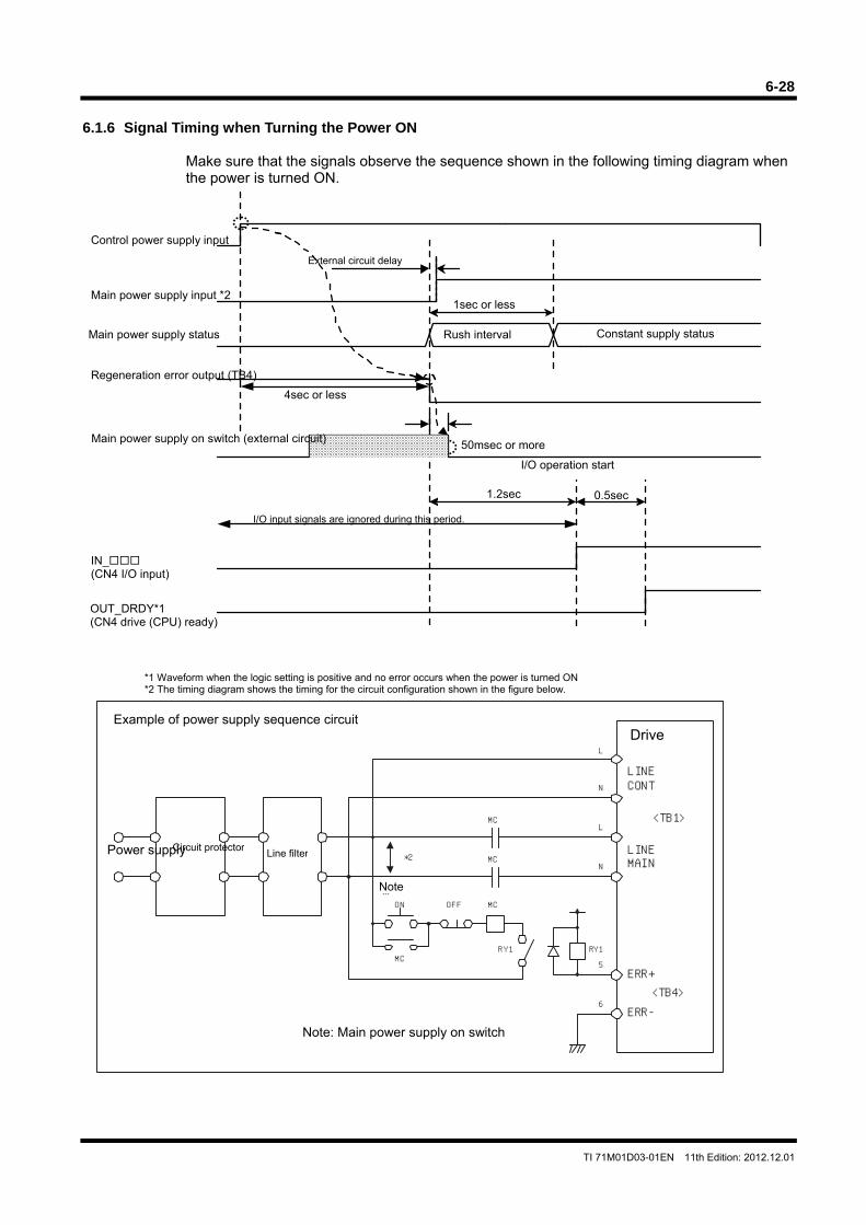
6-28
TI 71M01D03-01EN 11th Edition: 2012.12.01
RY1
ON OFF
MC
MC
MC
MCRY1
LINECONT
LINEMAIN
<TB1>
<TB4>ERR+
ERR-
※
L
L
N
N
5
6
*2Line filter Circuit protector Power supply
Note
6.1.6 Signal Timing when Turning the Power ON
Make sure that the signals observe the sequence shown in the following timing diagram when the power is turned ON.
*1 Waveform when the logic setting is positive and no error occurs when the power is turned ON *2 The timing diagram shows the timing for the circuit configuration shown in the figure below.
Note: Main power supply on switch
Example of power supply sequence circuit
Main power supply input *2
Control power supply input
Main power supply status
Regeneration error output (TB4)
Main power supply on switch (external circuit)
Rush interval Constant supply status
External circuit delay
1sec or less
4sec or less
50msec or more
IN_ (CN4 I/O input)
I/O input signals are ignored during this period.
OUT_DRDY*1 (CN4 drive (CPU) ready)
I/O operation start
1.2sec 0.5sec
Drive
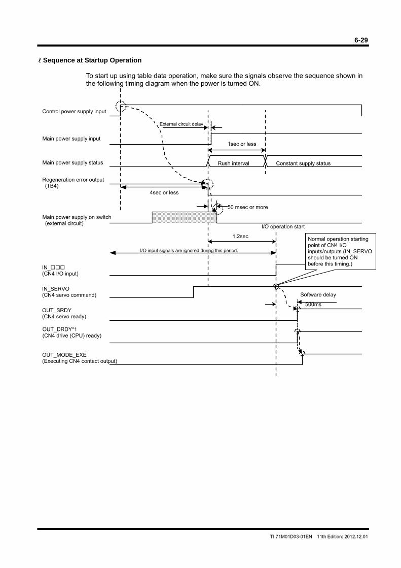
6-29
TI 71M01D03-01EN 11th Edition: 2012.12.01
Sequence at Startup Operation
To start up using table data operation, make sure the signals observe the sequence shown in the following timing diagram when the power is turned ON.
1.2sec
Main power supply input
Control power supply input
Main power supply status
Regeneration error output (TB4)
Main power supply on switch (external circuit)
Rush interval Constant supply status
External circuit delay
1sec or less
IN_ (CN4 I/O input)
4sec or less
50 msec or more
I/O input signals are ignored during this period.
OUT_DRDY*1 (CN4 drive (CPU) ready)
IN_SERVO (CN4 servo command)
OUT_SRDY (CN4 servo ready)
Software delay
500ms
OUT_MODE_EXE (Executing CN4 contact output)
I/O operation start
Normal operation starting point of CN4 I/O inputs/outputs (IN_SERVO should be turned ON before this timing.)
6-30
TI 71M01D03-01EN 11th Edition: 2012.12.01
6.1.7 Coordinate Systems (1) Rotation Coordinate System and Linear Coordinate System
Two coordinate systems, a rotation coordinate system and a linear coordinate system, are provided. Select the coordinate system to be used according to the system specifications. The rotation coordinate system is selected at shipment from the factory. When the rotation coordinate system is used, the software EOT function is set to invalid. In the rotation coordinate system, coordinates are expressed as "(scaling data -1)" starting from 0. When the motor has completed a full rotation and returns to the home position, the coordinate value returns to 0. In the linear coordinate system, the coordinate values do not return to 0 when the motor rotates more than one rotation from the home position, and the position is integrated. <How to switch between the rotation coordinate system and linear coordinate system> STEP 1 Select [#parameter] from the main menu of the utility software. STEP 2 Open the Register parameter tab and then the System Setup Register 1 panel. STEP 3 Select from [Select Coordinate System] in the [System Setup Register].
Rotation Coordinate System
The coordinate range of the rotation coordinate system is as follows: Command unit: From 0 (value of #112 - 1) Pulse: From 0 (value of #113 - 1)
#112: Scaling data ratio denominator (on the command unit) #113: Scaling data ratio numerator (on the pulse unit)
Linear Coordinate System
There are the following restrictions on the coordinate range of the linear coordinate system. Command unit:
Limit value on the + side: The smaller value of 2147483647 x and 999999998
Limit value on the - side: The greater value of -2147483647 x and –999999998
Pulse:
Limit value on the + side: The smaller value of 2147483647 and 999999998 Limit value on the - side: The smaller value of -2147483647 and -999999998
When using the linear coordinate system, a software EOT error occurs if the command unit instruction value exceeds the coordinate system limit range (ERR44.0: + direction software EOT, ERR45.0: - direction software EOT).
#113
#112
TIP
#113
#112
#112
#113
#112
#113

6-31
TI 71M01D03-01EN 11th Edition: 2012.12.01
(2) Setting the Direction of Coordinate Systems
It is possible to reverse the rotation direction of the motor and the torque output direction in the torque/thrust control mode. <Setting method> STEP 1 Select [#parameter] from the main menu of the utility software. STEP 2 Open the Register parameter tab and then the System Setup Register 1 panel. STEP 3 Set the rotation direction in Coordinate System Forward Direction Setting from the
System Setup Register 1 panel.
Rotation Direction Corresponding to the Coordinate System Forward Direction Setting Status (Output Torque Direction in the Torque/Thrust Control Mode)
Coordinate system forward direction
setting: Forward direction Coordinate system forward direction
setting: Backward direction CW direction CCW direction CW direction CCW direction
Jog move IN_JOG_UP IN_JOG_DN IN_JOG_DN IN_JOG_UP
Table data operation + direction - direction - direction + direction
Position control mode + direction - direction - direction + direction
Velocity control mode Positive voltage Negative voltage Negative voltage Positive voltage
Torque/thrust control mode Positive voltage Negative voltage Negative voltage Positive voltage
Coordinate system forward direction setting is preset to "Valid" at shipment from the factory.
CW direction
CCW direction
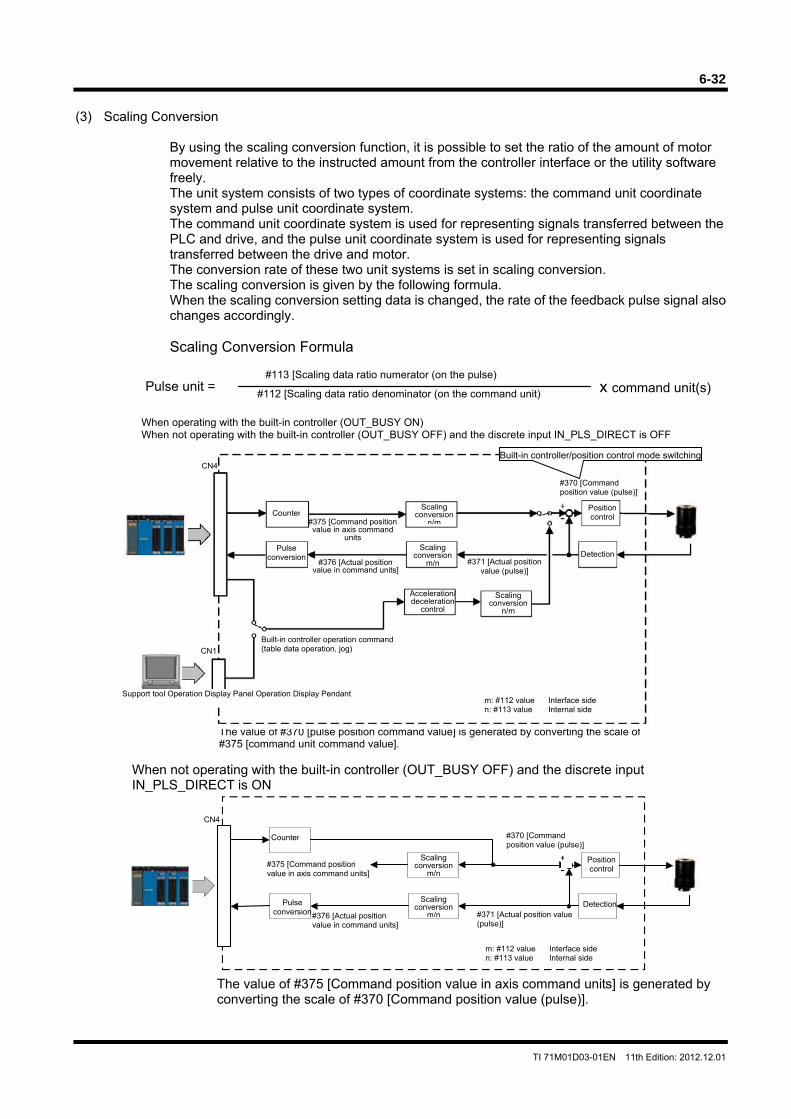
6-32
TI 71M01D03-01EN 11th Edition: 2012.12.01
m: #112 value Interface siden: #113 value Internal side
(3) Scaling Conversion
By using the scaling conversion function, it is possible to set the ratio of the amount of motor movement relative to the instructed amount from the controller interface or the utility software freely. The unit system consists of two types of coordinate systems: the command unit coordinate system and pulse unit coordinate system. The command unit coordinate system is used for representing signals transferred between the PLC and drive, and the pulse unit coordinate system is used for representing signals transferred between the drive and motor. The conversion rate of these two unit systems is set in scaling conversion. The scaling conversion is given by the following formula. When the scaling conversion setting data is changed, the rate of the feedback pulse signal also changes accordingly. Scaling Conversion Formula
When operating with the built-in controller (OUT_BUSY ON) When not operating with the built-in controller (OUT_BUSY OFF) and the discrete input IN_PLS_DIRECT is OFF
When not operating with the built-in controller (OUT_BUSY OFF) and the discrete input IN_PLS_DIRECT is ON
The value of #375 [Command position value in axis command units] is generated by converting the scale of #370 [Command position value (pulse)].
Pulse unit =#112 [Scaling data ratio denominator (on the command unit)
#113 [Scaling data ratio numerator (on the pulse)x command unit(s)
The value of #370 [pulse position command value] is generated by converting the scale of#375 [command unit command value].
m: #112 value Interface side n: #113 value Internal side
Counter
Pulse conversion
Position control
Detection
Scaling conversion
n/m
Scalingconversion
m/n
Scalingconversion
n/m
Acceleration/deceleration
control
Support tool Operation Display Panel Operation Display Pendant
Built-in controller/position control mode switching
Built-in controller operation command (table data operation, jog)
#375 [Command positionvalue in axis command
units
#370 [Command position value (pulse)]
#371 [Actual position value (pulse)]
CN4
CN1
#376 [Actual positionvalue in command units]
Counter
Pulse conversion
Position control
Detection
Scalingconversion
m/n
Scalingconversion
m/n
#375 [Command position value in axis command units]
#376 [Actual position value in command units]
#370 [Command position value (pulse)]
#371 [Actual position value (pulse)]
CN4
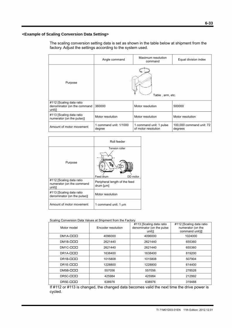
6-33
TI 71M01D03-01EN 11th Edition: 2012.12.01
<Example of Scaling Conversion Data Setting>
The scaling conversion setting data is set as shown in the table below at shipment from the factory. Adjust the settings according to the system used.
Angle command Maximum resolution
command Equal division index
Purpose
Table , arm, etc.
#112 [Scaling data ratio denominator (on the command unit)]
360000 Motor resolution 500000
#113 [Scaling data ratio numerator (on the pulse)]
Motor resolution Motor resolution Motor resolution
Amount of motor movement 1 command unit: 1/1000 degree
1 command unit: 1 pulse of motor resolution
100,000 command unit: 72 degrees
Roll feeder
Purpose
Tension roller
Feed drum DD motor#112 [Scaling data ratio numerator (on the command unit)]
Peripheral length of the feed drum [μm]
#113 [Scaling data ratio denominator (on the pulse)]
Motor resolution
Amount of motor movement 1 command unit: 1 μm
Scaling Conversion Data Values at Shipment from the Factory
Motor model Encoder resolution #113 [Scaling data ratio
denominator (on the pulse unit)]
#112 [Scaling data ratio numerator (on the command unit)]]
DM1A- 4096000 4096000 1024000
DM1B- 2621440 2621440 655360
DM1C- 2621440 2621440 655360
DR1A- 1638400 1638400 819200
DR1B- 1015808 1015808 507904
DR1E- 1228800 1228800 614400
DM5B- 557056 557056 278528
DR5C- 425984 425984 212992
DR5E- 638976 638976 319488
If #112 or #113 is changed, the changed data becomes valid the next time the drive power is cycled.
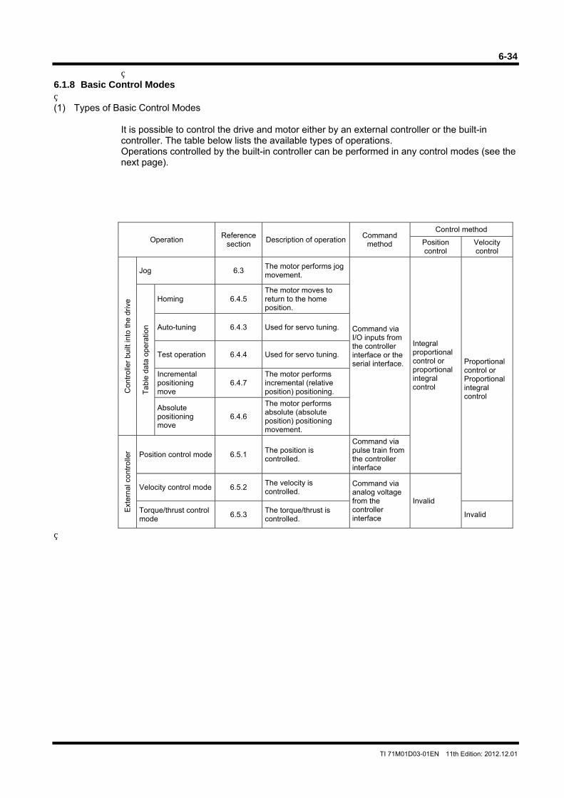
6-34
TI 71M01D03-01EN 11th Edition: 2012.12.01
6.1.8 Basic Control Modes (1) Types of Basic Control Modes
It is possible to control the drive and motor either by an external controller or the built-in controller. The table below lists the available types of operations. Operations controlled by the built-in controller can be performed in any control modes (see the next page).
Operation Reference
section Description of operation
Command method
Control method
Position control
Velocity control
Con
trol
ler
built
into
the
driv
e
Jog 6.3 The motor performs jog movement.
Command via I/O inputs from the controller interface or the serial interface.
Integral proportional control or proportional integral control
Proportional control or Proportional integral control
Tab
le d
ata
oper
atio
n
Homing 6.4.5 The motor moves to return to the home position.
Auto-tuning 6.4.3 Used for servo tuning.
Test operation 6.4.4 Used for servo tuning.
Incremental positioning move
6.4.7 The motor performs incremental (relative position) positioning.
Absolute positioning move
6.4.6
The motor performs absolute (absolute position) positioning movement.
Ext
erna
l con
trol
ler Position control mode 6.5.1
The position is controlled.
Command via pulse train from the controller interface
Velocity control mode 6.5.2 The velocity is controlled.
Command via analog voltage from the controller interface
Invalid Torque/thrust control mode
6.5.3 The torque/thrust is controlled.
Invalid
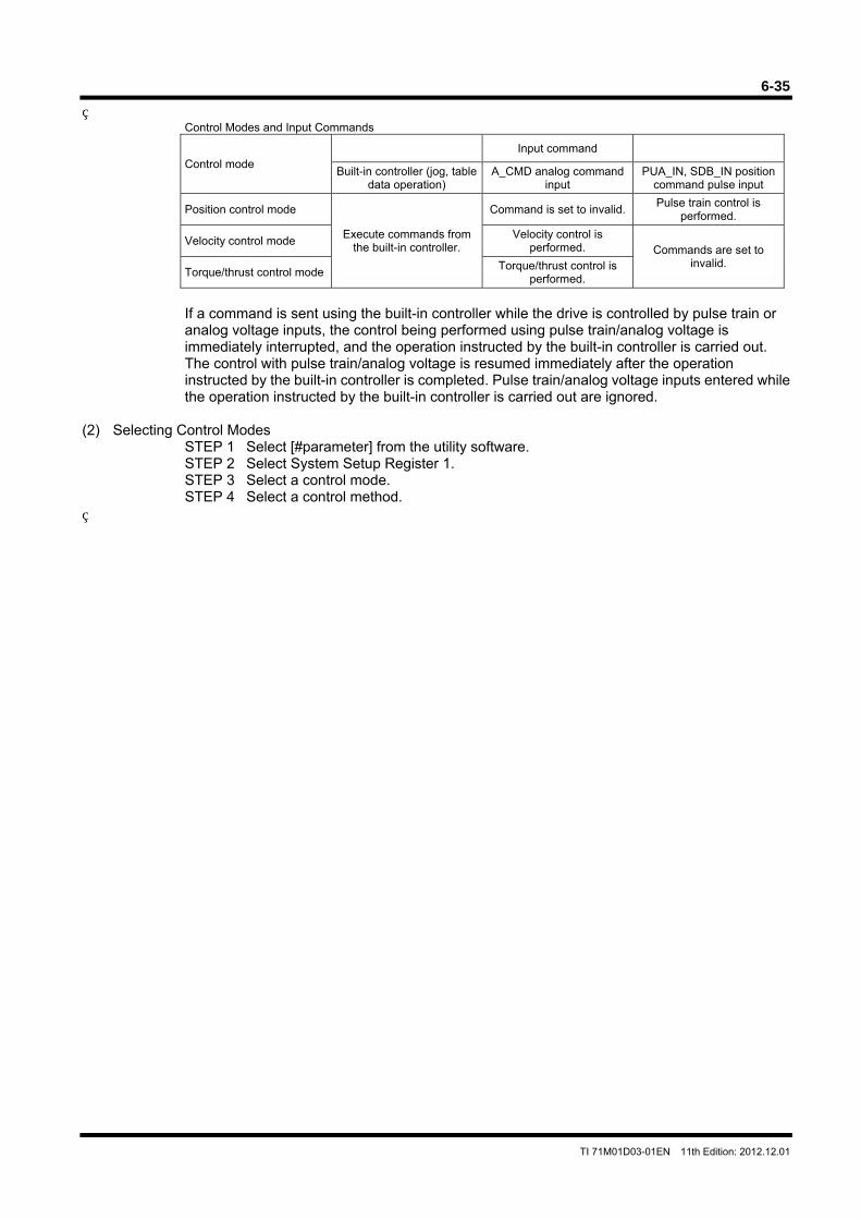
6-35
TI 71M01D03-01EN 11th Edition: 2012.12.01
Control Modes and Input Commands
Control mode Input command
Built-in controller (jog, table data operation)
A_CMD analog command input
PUA_IN, SDB_IN position command pulse input
Position control mode
Execute commands from the built-in controller.
Command is set to invalid. Pulse train control is
performed.
Velocity control mode Velocity control is
performed. Commands are set to invalid.
Torque/thrust control mode Torque/thrust control is
performed.
If a command is sent using the built-in controller while the drive is controlled by pulse train or analog voltage inputs, the control being performed using pulse train/analog voltage is immediately interrupted, and the operation instructed by the built-in controller is carried out. The control with pulse train/analog voltage is resumed immediately after the operation instructed by the built-in controller is completed. Pulse train/analog voltage inputs entered while the operation instructed by the built-in controller is carried out are ignored.
(2) Selecting Control Modes STEP 1 Select [#parameter] from the utility software. STEP 2 Select System Setup Register 1. STEP 3 Select a control mode. STEP 4 Select a control method.
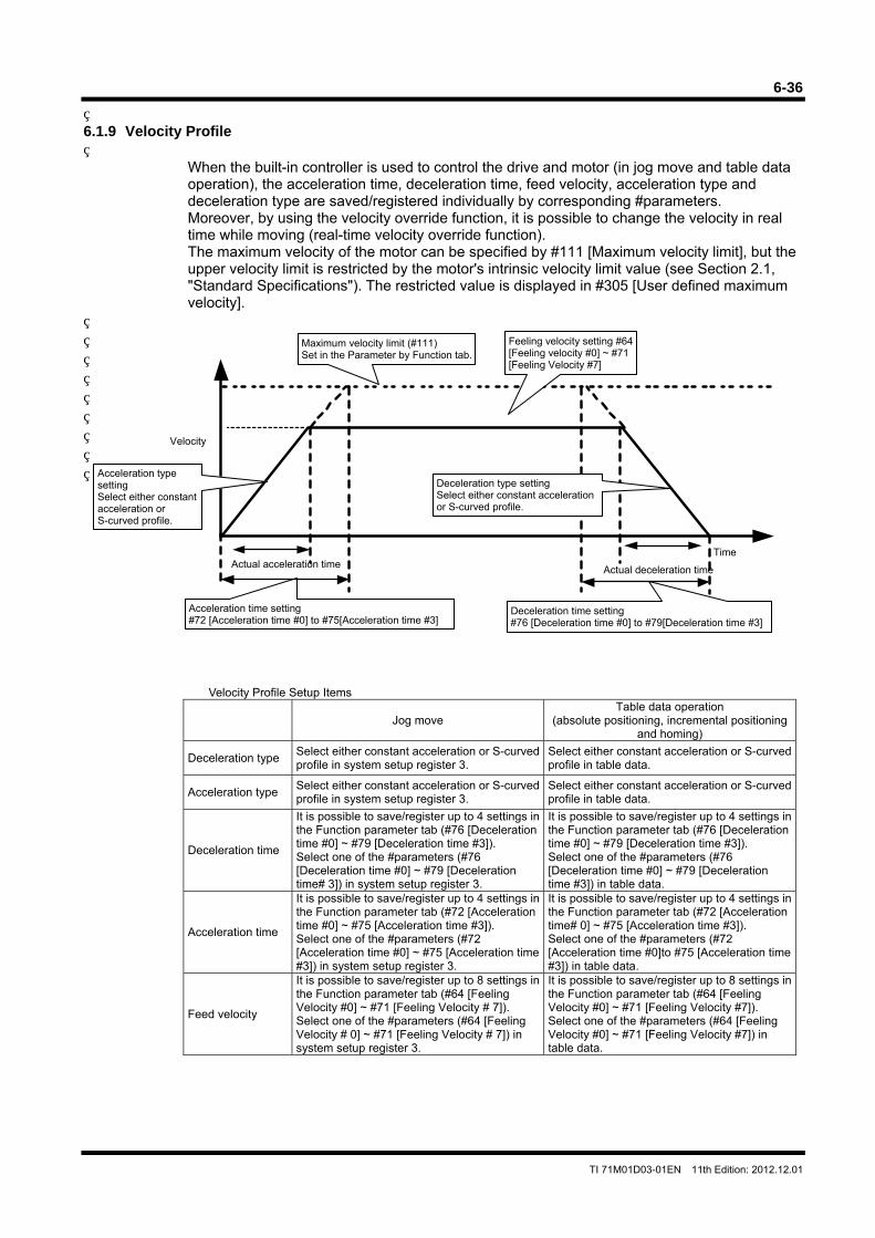
6-36
TI 71M01D03-01EN 11th Edition: 2012.12.01
6.1.9 Velocity Profile
When the built-in controller is used to control the drive and motor (in jog move and table data operation), the acceleration time, deceleration time, feed velocity, acceleration type and deceleration type are saved/registered individually by corresponding #parameters. Moreover, by using the velocity override function, it is possible to change the velocity in real time while moving (real-time velocity override function). The maximum velocity of the motor can be specified by #111 [Maximum velocity limit], but the upper velocity limit is restricted by the motor's intrinsic velocity limit value (see Section 2.1, "Standard Specifications"). The restricted value is displayed in #305 [User defined maximum velocity].
Velocity Profile Setup Items
Jog move Table data operation
(absolute positioning, incremental positioning and homing)
Deceleration type Select either constant acceleration or S-curved profile in system setup register 3.
Select either constant acceleration or S-curved profile in table data.
Acceleration type Select either constant acceleration or S-curved profile in system setup register 3.
Select either constant acceleration or S-curved profile in table data.
Deceleration time
It is possible to save/register up to 4 settings in the Function parameter tab (#76 [Deceleration time #0] ~ #79 [Deceleration time #3]). Select one of the #parameters (#76 [Deceleration time #0] ~ #79 [Deceleration time# 3]) in system setup register 3.
It is possible to save/register up to 4 settings in the Function parameter tab (#76 [Deceleration time #0] ~ #79 [Deceleration time #3]). Select one of the #parameters (#76 [Deceleration time #0] ~ #79 [Deceleration time #3]) in table data.
Acceleration time
It is possible to save/register up to 4 settings in the Function parameter tab (#72 [Acceleration time #0] ~ #75 [Acceleration time #3]). Select one of the #parameters (#72 [Acceleration time #0] ~ #75 [Acceleration time #3]) in system setup register 3.
It is possible to save/register up to 4 settings in the Function parameter tab (#72 [Acceleration time# 0] ~ #75 [Acceleration time #3]). Select one of the #parameters (#72 [Acceleration time #0]to #75 [Acceleration time #3]) in table data.
Feed velocity
It is possible to save/register up to 8 settings in the Function parameter tab (#64 [Feeling Velocity #0] ~ #71 [Feeling Velocity # 7]). Select one of the #parameters (#64 [Feeling Velocity # 0] ~ #71 [Feeling Velocity # 7]) in system setup register 3.
It is possible to save/register up to 8 settings in the Function parameter tab (#64 [Feeling Velocity #0] ~ #71 [Feeling Velocity #7]). Select one of the #parameters (#64 [Feeling Velocity #0] ~ #71 [Feeling Velocity #7]) in table data.
Deceleration time setting #76 [Deceleration time #0] to #79[Deceleration time #3]
Velocity
Actual acceleration time Actual deceleration time
Time
Deceleration type setting Select either constant acceleration or S-curved profile.
Acceleration type setting Select either constant acceleration or S-curved profile.
Acceleration time setting #72 [Acceleration time #0] to #75[Acceleration time #3]
Maximum velocity limit (#111) Set in the Parameter by Function tab.
Feeling velocity setting #64 [Feeling velocity #0] ~ #71 [Feeling Velocity #7]
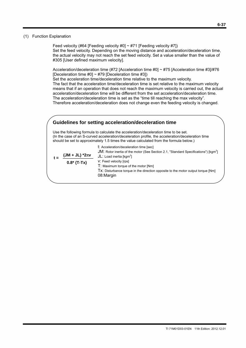
6-37
TI 71M01D03-01EN 11th Edition: 2012.12.01
(1) Function Explanation
Feed velocity (#64 [Feeding velocity #0] ~ #71 [Feeding velocity #7]) Set the feed velocity. Depending on the moving distance and acceleration/deceleration time, the actual velocity may not reach the set feed velocity. Set a value smaller than the value of #305 [User defined maximum velocity]. Acceleration/deceleration time (#72 [Acceleration time #0] ~ #75 [Acceleration time #3]/#76 [Deceleration time #0] ~ #79 [Deceleration time #3]) Set the acceleration time/deceleration time relative to the maximum velocity. The fact that the acceleration time/deceleration time is set relative to the maximum velocity means that if an operation that does not reach the maximum velocity is carried out, the actual acceleration/deceleration time will be different from the set acceleration/deceleration time. The acceleration/deceleration time is set as the “time till reaching the max velocity”. Therefore acceleration/deceleration does not change even the feeding velocity is changed.
Guidelines for setting acceleration/deceleration time
Use the following formula to calculate the acceleration/deceleration time to be set. (In the case of an S-curved acceleration/deceleration profile, the acceleration/deceleration time should be set to approximately 1.5 times the value calculated from the formula below.)
t: Acceleration/deceleration time [sec] JM: Rotor inertia of the motor (See Section 2.1, "Standard Specifications") [kgm2] JL: Load inertia [kgm2] v: Feed velocity [rps] T: Maximum torque of the motor [Nm] Tx: Disturbance torque in the direction opposite to the motor output torque [Nm] 08:Margin
t =
0.8* (T-Tx)
(JM + JL) *2πv
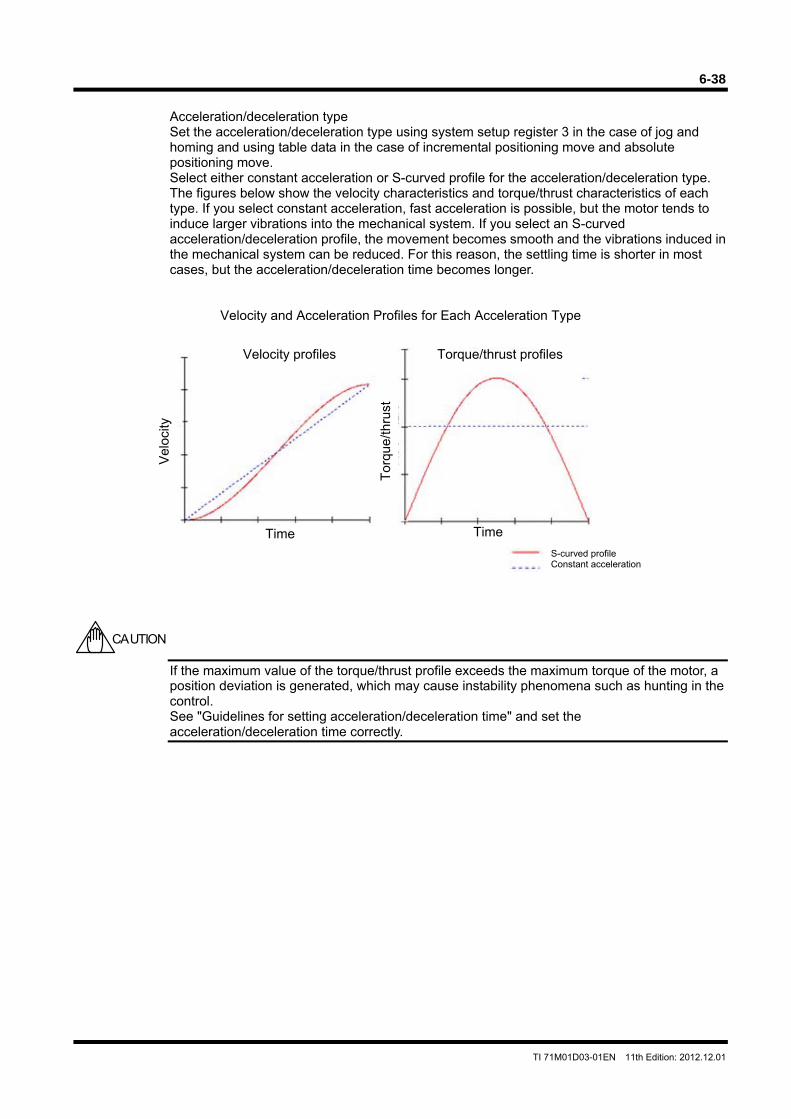
6-38
TI 71M01D03-01EN 11th Edition: 2012.12.01
Acceleration/deceleration type Set the acceleration/deceleration type using system setup register 3 in the case of jog and homing and using table data in the case of incremental positioning move and absolute positioning move. Select either constant acceleration or S-curved profile for the acceleration/deceleration type. The figures below show the velocity characteristics and torque/thrust characteristics of each type. If you select constant acceleration, fast acceleration is possible, but the motor tends to induce larger vibrations into the mechanical system. If you select an S-curved acceleration/deceleration profile, the movement becomes smooth and the vibrations induced in the mechanical system can be reduced. For this reason, the settling time is shorter in most cases, but the acceleration/deceleration time becomes longer.
Velocity and Acceleration Profiles for Each Acceleration Type
If the maximum value of the torque/thrust profile exceeds the maximum torque of the motor, a position deviation is generated, which may cause instability phenomena such as hunting in the control. See "Guidelines for setting acceleration/deceleration time" and set the acceleration/deceleration time correctly.
CAUTION
Torque/thrust profiles Velocity profiles
Tor
que/
thru
st
Vel
ocity
Time Time S-curved profile Constant acceleration
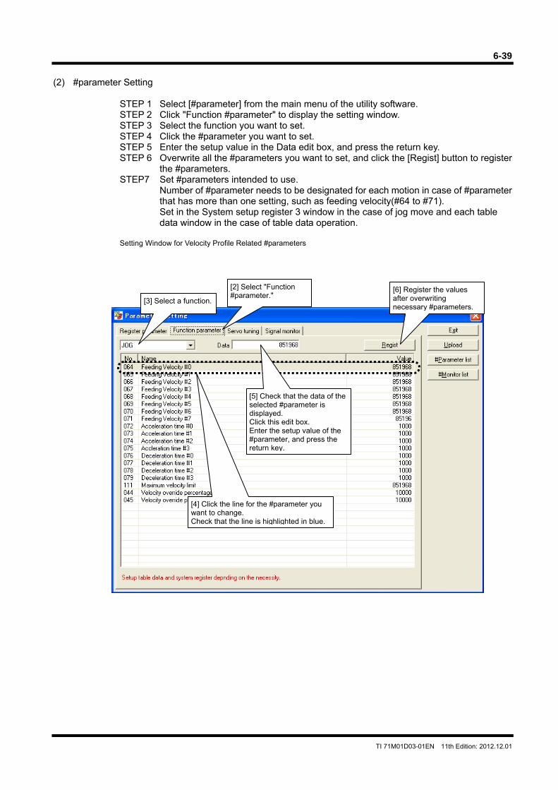
6-39
TI 71M01D03-01EN 11th Edition: 2012.12.01
(2) #parameter Setting
STEP 1 Select [#parameter] from the main menu of the utility software. STEP 2 Click "Function #parameter" to display the setting window. STEP 3 Select the function you want to set. STEP 4 Click the #parameter you want to set. STEP 5 Enter the setup value in the Data edit box, and press the return key. STEP 6 Overwrite all the #parameters you want to set, and click the [Regist] button to register
the #parameters. STEP7 Set #parameters intended to use.
Number of #parameter needs to be designated for each motion in case of #parameter that has more than one setting, such as feeding velocity(#64 to #71). Set in the System setup register 3 window in the case of jog move and each table data window in the case of table data operation.
Setting Window for Velocity Profile Related #parameters
[3] Select a function.
[2] Select "Function #parameter."
[6] Register the values after overwriting necessary #parameters.
[4] Click the line for the #parameter you want to change. Check that the line is highlighted in blue.
[5] Check that the data of the selected #parameter is displayed. Click this edit box. Enter the setup value of the #parameter, and press the return key.
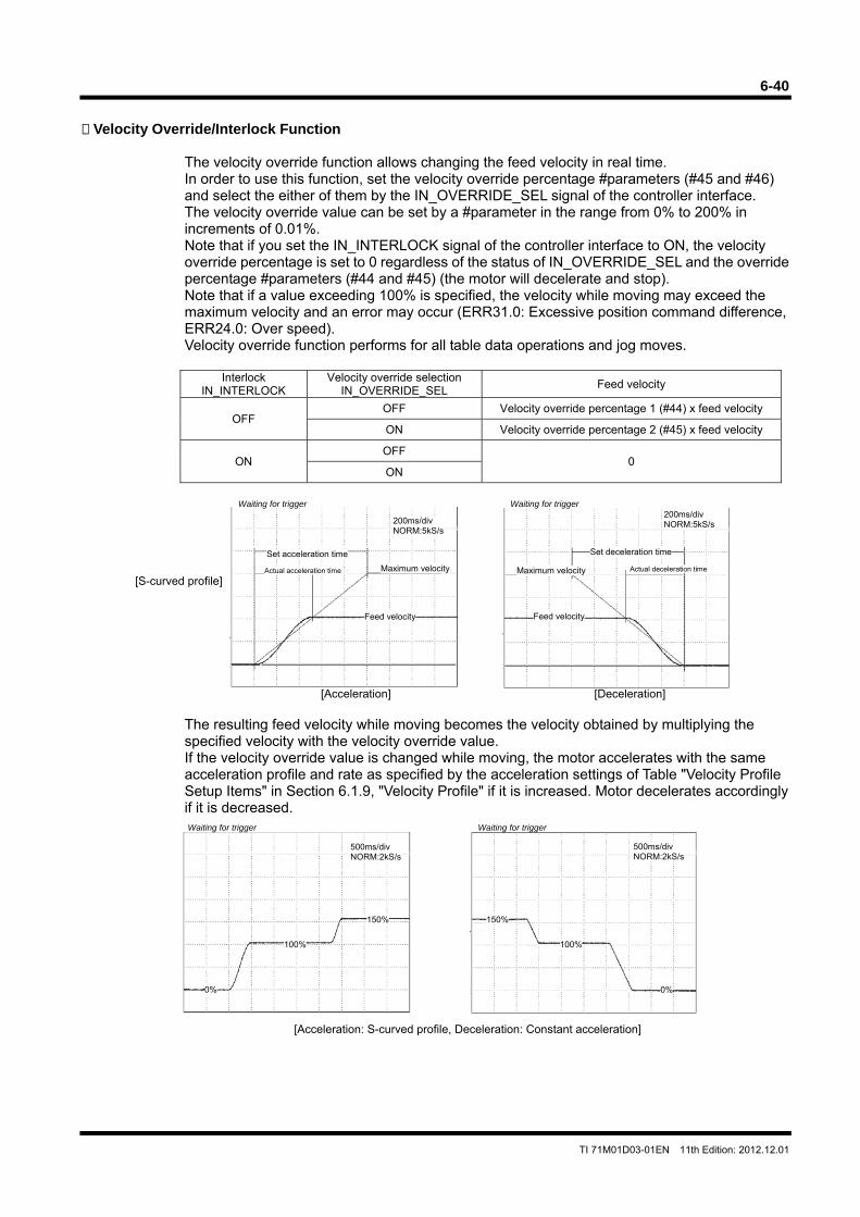
6-40
TI 71M01D03-01EN 11th Edition: 2012.12.01
200ms/div
NORM:5kS/s 200ms/div
NORM:5kS/s
[S-curved profile]
[Acceleration] [Deceleration]
Waiting for trigger
Feed velocity
Maximum velocity
Set acceleration time
Actual acceleration time
200ms/div NORM:5kS/s
Waiting for trigger
Feed velocity
Maximum velocity
Set deceleration time
Actual deceleration time
200ms/div NORM:5kS/s
500ms/divNORM:2kS/s
500ms/divNORM:2kS/s
[Acceleration: S-curved profile, Deceleration: Constant acceleration]
Waiting for trigger
500ms/div NORM:2kS/s
150%
100%
0%
Waiting for trigger
150%
100%
0%
500ms/div NORM:2kS/s
Velocity Override/Interlock Function
The velocity override function allows changing the feed velocity in real time. In order to use this function, set the velocity override percentage #parameters (#45 and #46) and select the either of them by the IN_OVERRIDE_SEL signal of the controller interface. The velocity override value can be set by a #parameter in the range from 0% to 200% in increments of 0.01%. Note that if you set the IN_INTERLOCK signal of the controller interface to ON, the velocity override percentage is set to 0 regardless of the status of IN_OVERRIDE_SEL and the override percentage #parameters (#44 and #45) (the motor will decelerate and stop). Note that if a value exceeding 100% is specified, the velocity while moving may exceed the maximum velocity and an error may occur (ERR31.0: Excessive position command difference, ERR24.0: Over speed). Velocity override function performs for all table data operations and jog moves.
Interlock
IN_INTERLOCK Velocity override selection
IN_OVERRIDE_SEL Feed velocity
OFF OFF Velocity override percentage 1 (#44) x feed velocity
ON Velocity override percentage 2 (#45) x feed velocity
ON OFF
0 ON
The resulting feed velocity while moving becomes the velocity obtained by multiplying the specified velocity with the velocity override value. If the velocity override value is changed while moving, the motor accelerates with the same acceleration profile and rate as specified by the acceleration settings of Table "Velocity Profile Setup Items" in Section 6.1.9, "Velocity Profile" if it is increased. Motor decelerates accordingly if it is decreased.
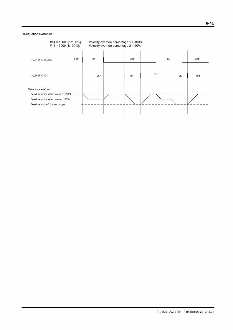
6-41
TI 71M01D03-01EN 11th Edition: 2012.12.01
<Sequence example>
#44 = 10000 [1/100%]: Velocity override percentage 1 = 100% #45 = 5000 [1/100%]: Velocity override percentage 2 = 50%
IN_OVERRIDE_SEL OFF
IN_INTERLOCK
ON
ON ON
ON
OFF
OFF
OFF OFF
OFF
Velocity waveform
Feed velocity setup value x 100%
Feed velocity setup value x 50%
Feed velocity 0 (motor stop)
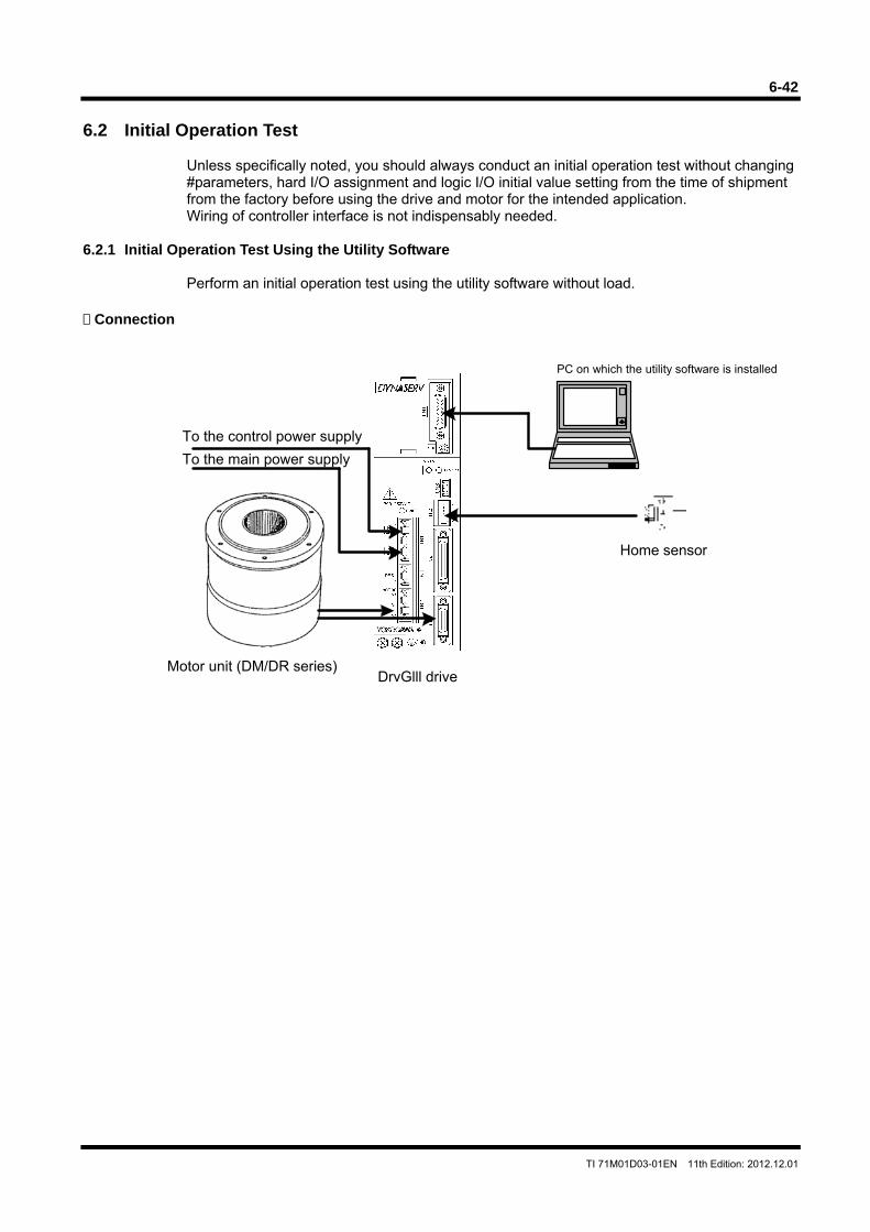
6-42
TI 71M01D03-01EN 11th Edition: 2012.12.01
6.2 Initial Operation Test
Unless specifically noted, you should always conduct an initial operation test without changing #parameters, hard I/O assignment and logic I/O initial value setting from the time of shipment from the factory before using the drive and motor for the intended application. Wiring of controller interface is not indispensably needed.
6.2.1 Initial Operation Test Using the Utility Software
Perform an initial operation test using the utility software without load. Connection
PC on which the utility software is installed
To the control power supply
Motor unit (DM/DR series)DrvGlll drive
To the main power supply
Home sensor
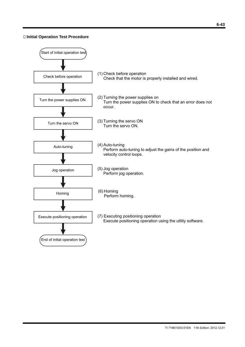
6-43
TI 71M01D03-01EN 11th Edition: 2012.12.01
Initial Operation Test Procedure
Start of initial operation test
Check before operation
Turn the servo ON
End of initial operation test
Turn the power supplies ON
Auto-tuning
Jog operation
Homing
(1) Check before operation Check that the motor is properly installed and wired.
(2) Turning the power supplies on Turn the power supplies ON to check that an error does not occur.
(3) Turning the servo ON Turn the servo ON.
(4) Auto-tuning Perform auto-tuning to adjust the gains of the position and velocity control loops.
(5) Jog operation Perform jog operation.
(6) Homing Perform homing.
Execute positioning operation (7) Executing positioning operation Execute positioning operation using the utility software.
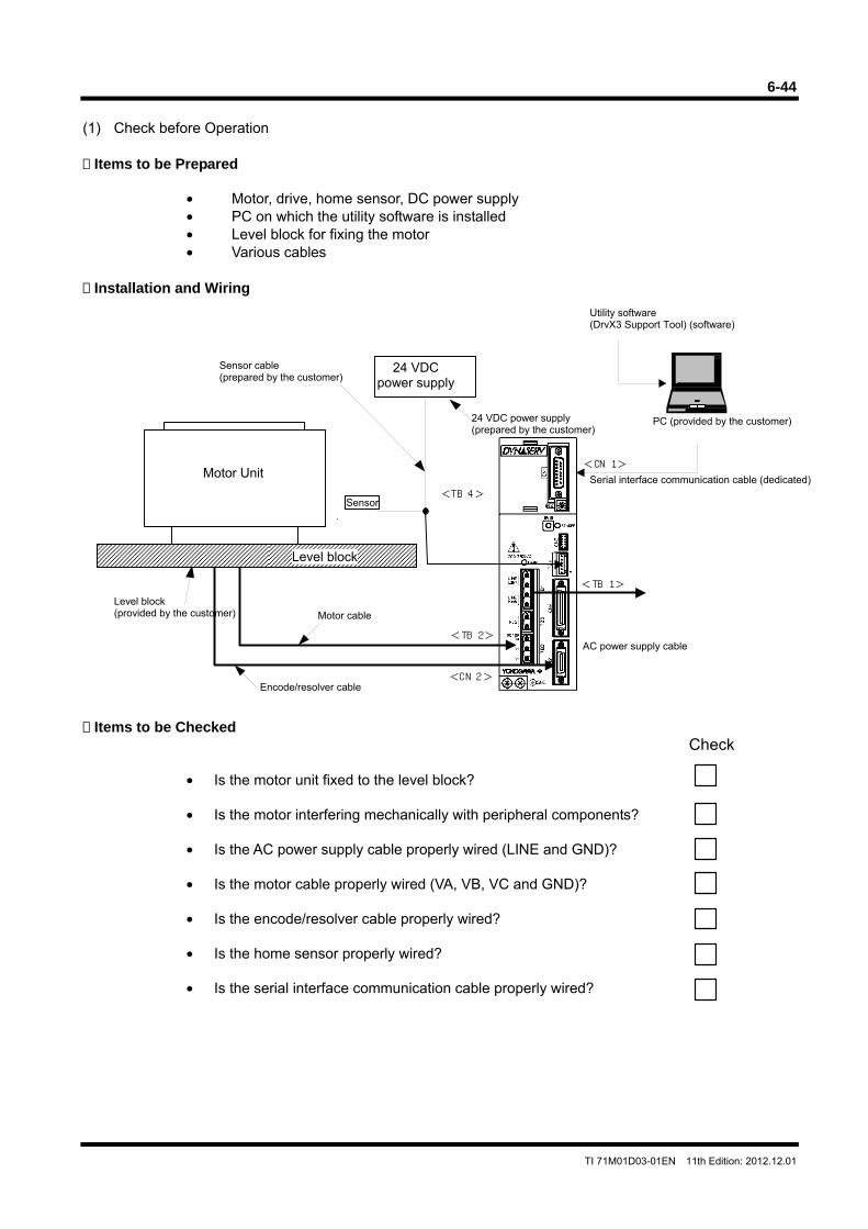
6-44
TI 71M01D03-01EN 11th Edition: 2012.12.01
<CN 2>
<TB 2>
<TB 4>
<CN 1>
<TB 1>
(1) Check before Operation Items to be Prepared
• Motor, drive, home sensor, DC power supply • PC on which the utility software is installed • Level block for fixing the motor • Various cables
Installation and Wiring
Items to be Checked
Check • Is the motor unit fixed to the level block? • Is the motor interfering mechanically with peripheral components? • Is the AC power supply cable properly wired (LINE and GND)? • Is the motor cable properly wired (VA, VB, VC and GND)? • Is the encode/resolver cable properly wired? • Is the home sensor properly wired? • Is the serial interface communication cable properly wired?
Sensor
AC power supply cable
Level block
Motor Unit
PC (provided by the customer)
Level block (provided by the customer) Motor cable
24 VDC power supply
24 VDC power supply (prepared by the customer)
Sensor cable (prepared by the customer)
Encode/resolver cable
Utility software (DrvX3 Support Tool) (software)
Serial interface communication cable (dedicated)
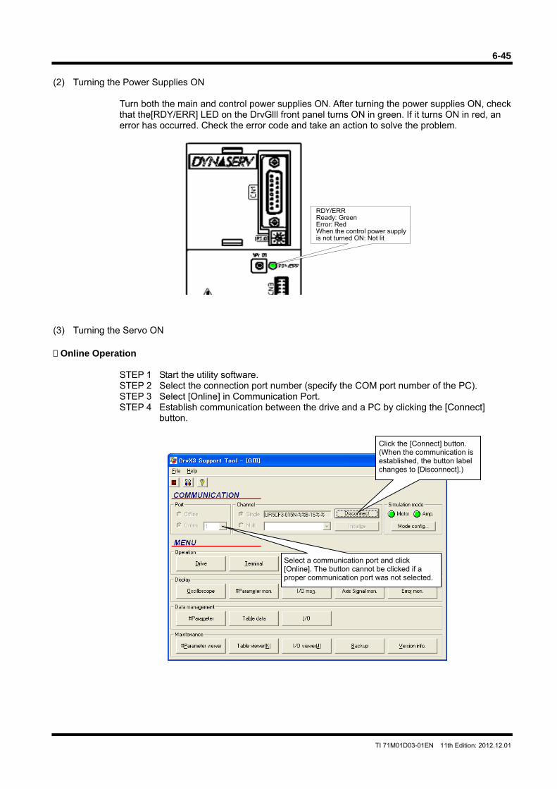
6-45
TI 71M01D03-01EN 11th Edition: 2012.12.01
(2) Turning the Power Supplies ON
Turn both the main and control power supplies ON. After turning the power supplies ON, check that the[RDY/ERR] LED on the DrvGlll front panel turns ON in green. If it turns ON in red, an error has occurred. Check the error code and take an action to solve the problem.
(3) Turning the Servo ON Online Operation
STEP 1 Start the utility software. STEP 2 Select the connection port number (specify the COM port number of the PC). STEP 3 Select [Online] in Communication Port. STEP 4 Establish communication between the drive and a PC by clicking the [Connect]
button.
Click the [Connect] button. (When the communication is established, the button label changes to [Disconnect].)
Select a communication port and click [Online]. The button cannot be clicked if a proper communication port was not selected.
RDY/ERRReady: Green Error: Red When the control power supply is not turned ON: Not lit
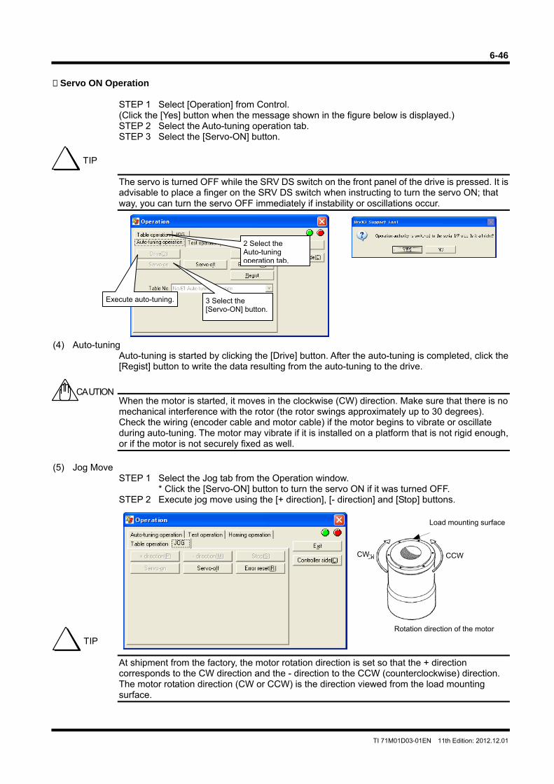
6-46
TI 71M01D03-01EN 11th Edition: 2012.12.01
Servo ON Operation
STEP 1 Select [Operation] from Control. (Click the [Yes] button when the message shown in the figure below is displayed.) STEP 2 Select the Auto-tuning operation tab. STEP 3 Select the [Servo-ON] button.
The servo is turned OFF while the SRV DS switch on the front panel of the drive is pressed. It is advisable to place a finger on the SRV DS switch when instructing to turn the servo ON; that way, you can turn the servo OFF immediately if instability or oscillations occur.
(4) Auto-tuning
Auto-tuning is started by clicking the [Drive] button. After the auto-tuning is completed, click the [Regist] button to write the data resulting from the auto-tuning to the drive.
When the motor is started, it moves in the clockwise (CW) direction. Make sure that there is no mechanical interference with the rotor (the rotor swings approximately up to 30 degrees). Check the wiring (encoder cable and motor cable) if the motor begins to vibrate or oscillate during auto-tuning. The motor may vibrate if it is installed on a platform that is not rigid enough, or if the motor is not securely fixed as well.
(5) Jog Move
STEP 1 Select the Jog tab from the Operation window. * Click the [Servo-ON] button to turn the servo ON if it was turned OFF.
STEP 2 Execute jog move using the [+ direction], [- direction] and [Stop] buttons.
At shipment from the factory, the motor rotation direction is set so that the + direction corresponds to the CW direction and the - direction to the CCW (counterclockwise) direction. The motor rotation direction (CW or CCW) is the direction viewed from the load mounting surface.
TIP
Execute auto-tuning. 3 Select the [Servo-ON] button.
2 Select the Auto-tuning operation tab.
CAUTION
TIP
CW
Rotation direction of the motor
CW CCW
Load mounting surface
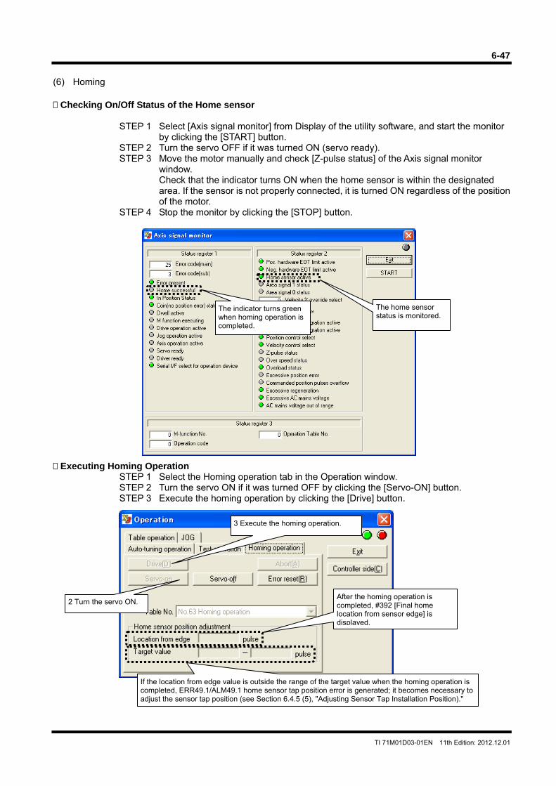
6-47
TI 71M01D03-01EN 11th Edition: 2012.12.01
(6) Homing Checking On/Off Status of the Home sensor
STEP 1 Select [Axis signal monitor] from Display of the utility software, and start the monitor
by clicking the [START] button. STEP 2 Turn the servo OFF if it was turned ON (servo ready). STEP 3 Move the motor manually and check [Z-pulse status] of the Axis signal monitor
window. Check that the indicator turns ON when the home sensor is within the designated area. If the sensor is not properly connected, it is turned ON regardless of the position of the motor.
STEP 4 Stop the monitor by clicking the [STOP] button.
Executing Homing Operation
STEP 1 Select the Homing operation tab in the Operation window. STEP 2 Turn the servo ON if it was turned OFF by clicking the [Servo-ON] button. STEP 3 Execute the homing operation by clicking the [Drive] button.
The indicator turns green when homing operation is completed.
The home sensor status is monitored.
3 Execute the homing operation.
2 Turn the servo ON. After the homing operation is completed, #392 [Final home location from sensor edge] is displayed.
If the location from edge value is outside the range of the target value when the homing operation is completed, ERR49.1/ALM49.1 home sensor tap position error is generated; it becomes necessary to adjust the sensor tap position (see Section 6.4.5 (5), "Adjusting Sensor Tap Installation Position)."
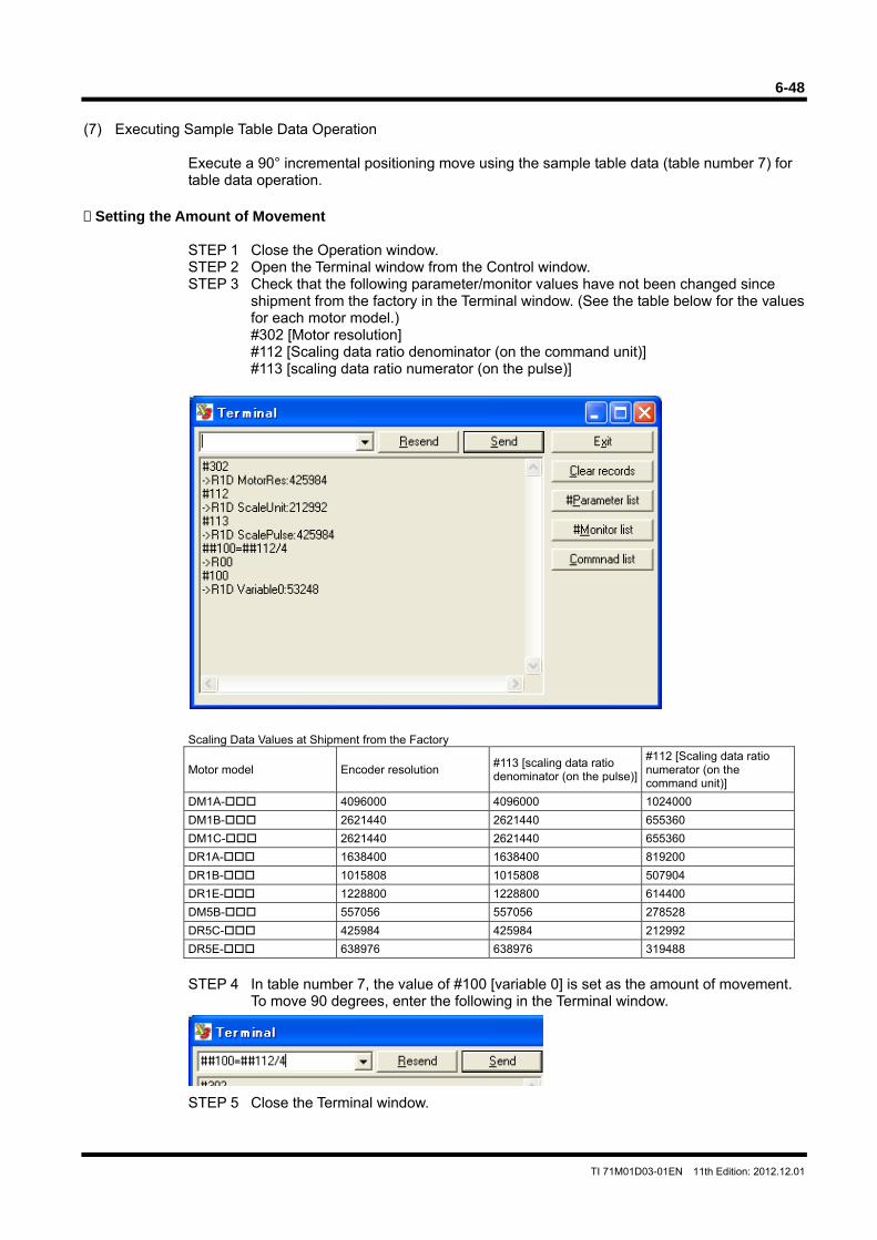
6-48
TI 71M01D03-01EN 11th Edition: 2012.12.01
(7) Executing Sample Table Data Operation
Execute a 90° incremental positioning move using the sample table data (table number 7) for table data operation.
Setting the Amount of Movement
STEP 1 Close the Operation window. STEP 2 Open the Terminal window from the Control window. STEP 3 Check that the following parameter/monitor values have not been changed since
shipment from the factory in the Terminal window. (See the table below for the values for each motor model.) #302 [Motor resolution] #112 [Scaling data ratio denominator (on the command unit)] #113 [scaling data ratio numerator (on the pulse)]
Scaling Data Values at Shipment from the Factory
Motor model Encoder resolution #113 [scaling data ratio denominator (on the pulse)]
#112 [Scaling data ratio numerator (on the command unit)]
DM1A- 4096000 4096000 1024000
DM1B- 2621440 2621440 655360
DM1C- 2621440 2621440 655360
DR1A- 1638400 1638400 819200
DR1B- 1015808 1015808 507904
DR1E- 1228800 1228800 614400
DM5B- 557056 557056 278528
DR5C- 425984 425984 212992
DR5E- 638976 638976 319488
STEP 4 In table number 7, the value of #100 [variable 0] is set as the amount of movement.
To move 90 degrees, enter the following in the Terminal window.
STEP 5 Close the Terminal window.
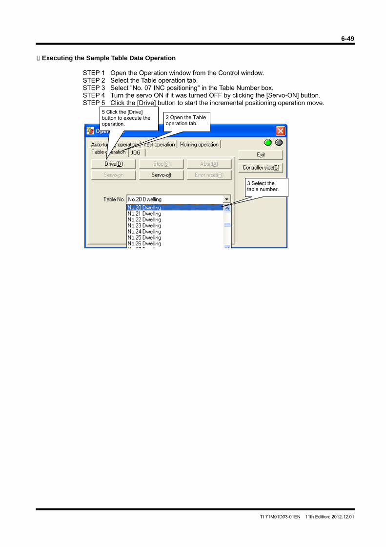
6-49
TI 71M01D03-01EN 11th Edition: 2012.12.01
Executing the Sample Table Data Operation
STEP 1 Open the Operation window from the Control window. STEP 2 Select the Table operation tab. STEP 3 Select "No. 07 INC positioning" in the Table Number box. STEP 4 Turn the servo ON if it was turned OFF by clicking the [Servo-ON] button. STEP 5 Click the [Drive] button to start the incremental positioning operation move.
5 Click the [Drive] button to execute the operation.
2 Open the Table operation tab.
3 Select the table number.
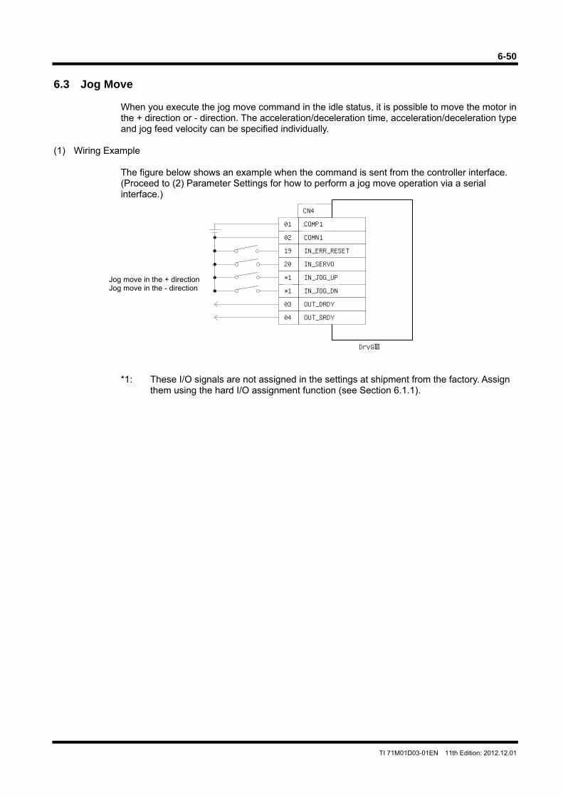
6-50
TI 71M01D03-01EN 11th Edition: 2012.12.01
6.3 Jog Move
When you execute the jog move command in the idle status, it is possible to move the motor in the + direction or - direction. The acceleration/deceleration time, acceleration/deceleration type and jog feed velocity can be specified individually.
(1) Wiring Example
The figure below shows an example when the command is sent from the controller interface. (Proceed to (2) Parameter Settings for how to perform a jog move operation via a serial interface.)
*1: These I/O signals are not assigned in the settings at shipment from the factory. Assign them using the hard I/O assignment function (see Section 6.1.1).
COMP1
COMN1
IN_JOG_UP
IN_JOG_DN
OUT_DRDY
OUT_SRDY
IN_SERVO
IN_ERR_RESET
01
02
19
20
*1
*1
03
04
CN4
DrvGIII
Jog move in the + direction Jog move in the - direction
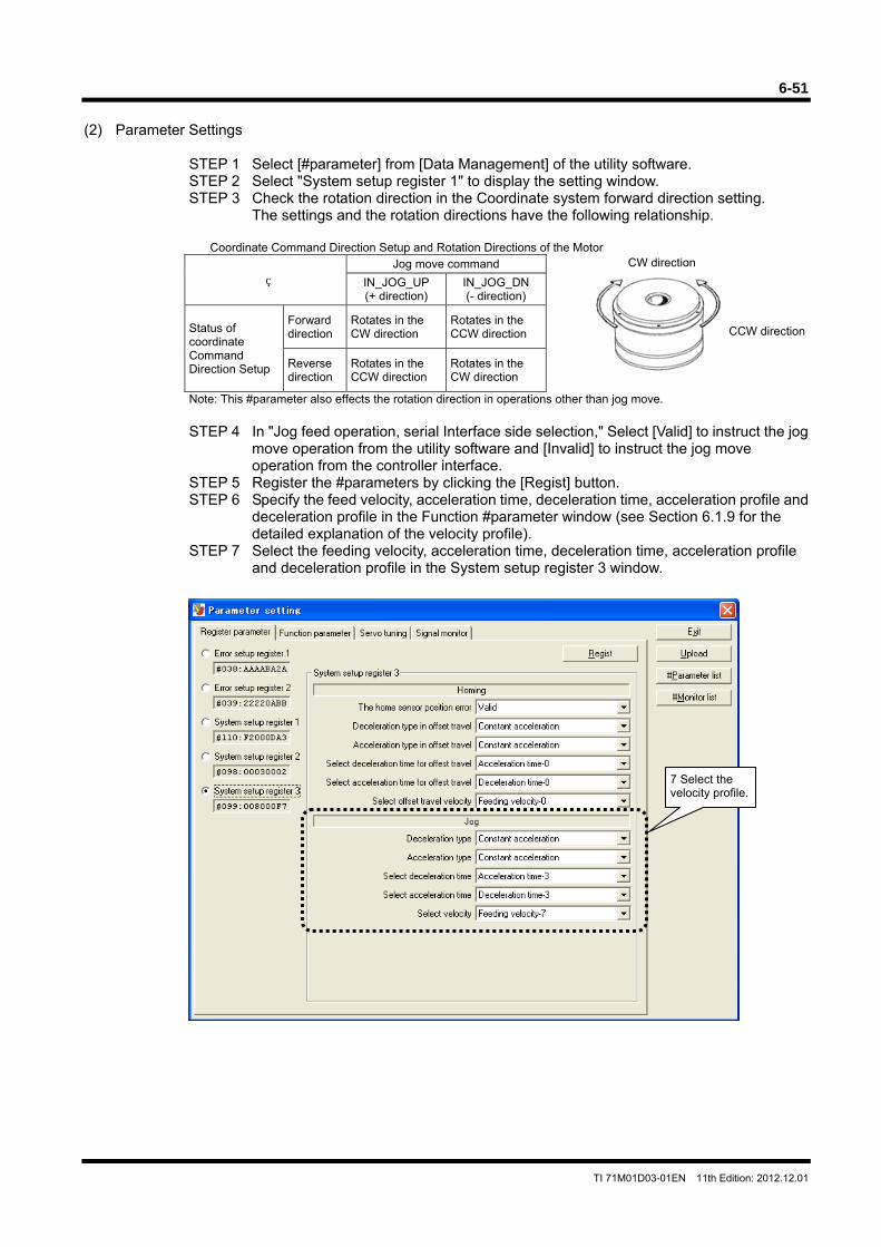
6-51
TI 71M01D03-01EN 11th Edition: 2012.12.01
CW direction
CCW direction
(2) Parameter Settings
STEP 1 Select [#parameter] from [Data Management] of the utility software. STEP 2 Select "System setup register 1" to display the setting window. STEP 3 Check the rotation direction in the Coordinate system forward direction setting.
The settings and the rotation directions have the following relationship.
Coordinate Command Direction Setup and Rotation Directions of the Motor
Jog move command
IN_JOG_UP (+ direction)
IN_JOG_DN (- direction)
Status of coordinate Command Direction Setup
Forward direction
Rotates in the CW direction
Rotates in the CCW direction
Reverse direction
Rotates in the CCW direction
Rotates in the CW direction
Note: This #parameter also effects the rotation direction in operations other than jog move.
STEP 4 In "Jog feed operation, serial Interface side selection," Select [Valid] to instruct the jog move operation from the utility software and [Invalid] to instruct the jog move operation from the controller interface.
STEP 5 Register the #parameters by clicking the [Regist] button. STEP 6 Specify the feed velocity, acceleration time, deceleration time, acceleration profile and
deceleration profile in the Function #parameter window (see Section 6.1.9 for the detailed explanation of the velocity profile).
STEP 7 Select the feeding velocity, acceleration time, deceleration time, acceleration profile and deceleration profile in the System setup register 3 window.
7 Select the velocity profile.
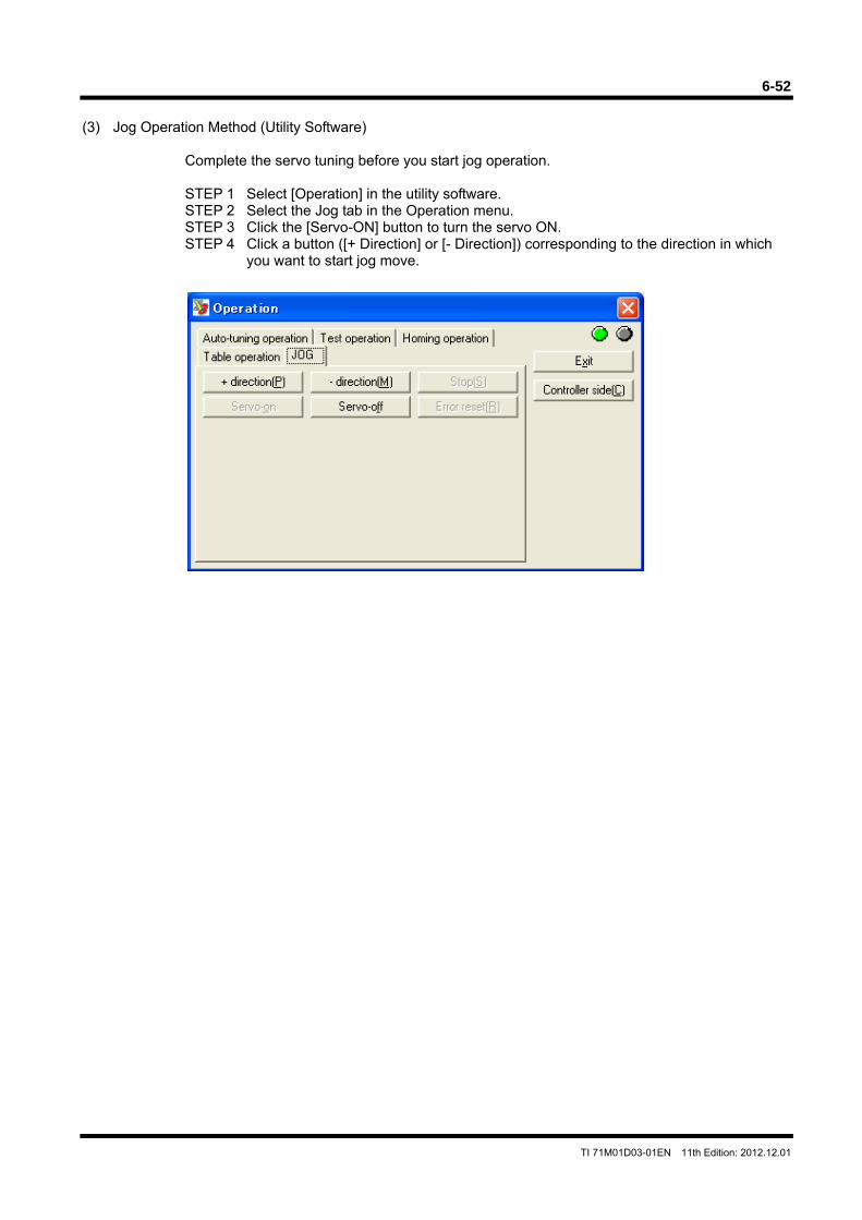
6-52
TI 71M01D03-01EN 11th Edition: 2012.12.01
(3) Jog Operation Method (Utility Software)
Complete the servo tuning before you start jog operation. STEP 1 Select [Operation] in the utility software. STEP 2 Select the Jog tab in the Operation menu. STEP 3 Click the [Servo-ON] button to turn the servo ON. STEP 4 Click a button ([+ Direction] or [- Direction]) corresponding to the direction in which
you want to start jog move.
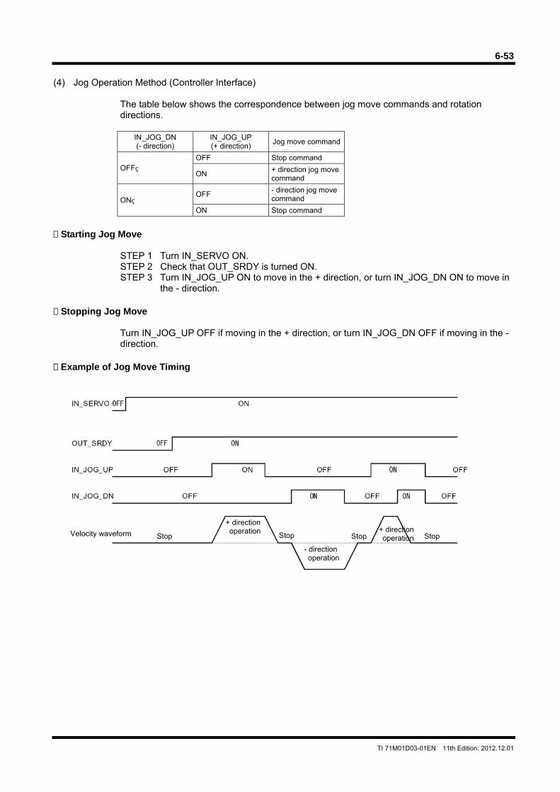
6-53
TI 71M01D03-01EN 11th Edition: 2012.12.01
(4) Jog Operation Method (Controller Interface)
The table below shows the correspondence between jog move commands and rotation directions.
IN_JOG_DN (- direction)
IN_JOG_UP (+ direction)
Jog move command
OFF OFF Stop command
ON + direction jog move command
ON OFF
- direction jog move command
ON Stop command
Starting Jog Move
STEP 1 Turn IN_SERVO ON. STEP 2 Check that OUT_SRDY is turned ON. STEP 3 Turn IN_JOG_UP ON to move in the + direction, or turn IN_JOG_DN ON to move in
the - direction. Stopping Jog Move
Turn IN_JOG_UP OFF if moving in the + direction, or turn IN_JOG_DN OFF if moving in the - direction.
Example of Jog Move Timing
Stop Stop Velocity waveform Stop Stop+ direction operation
+ direction operation
- direction operation
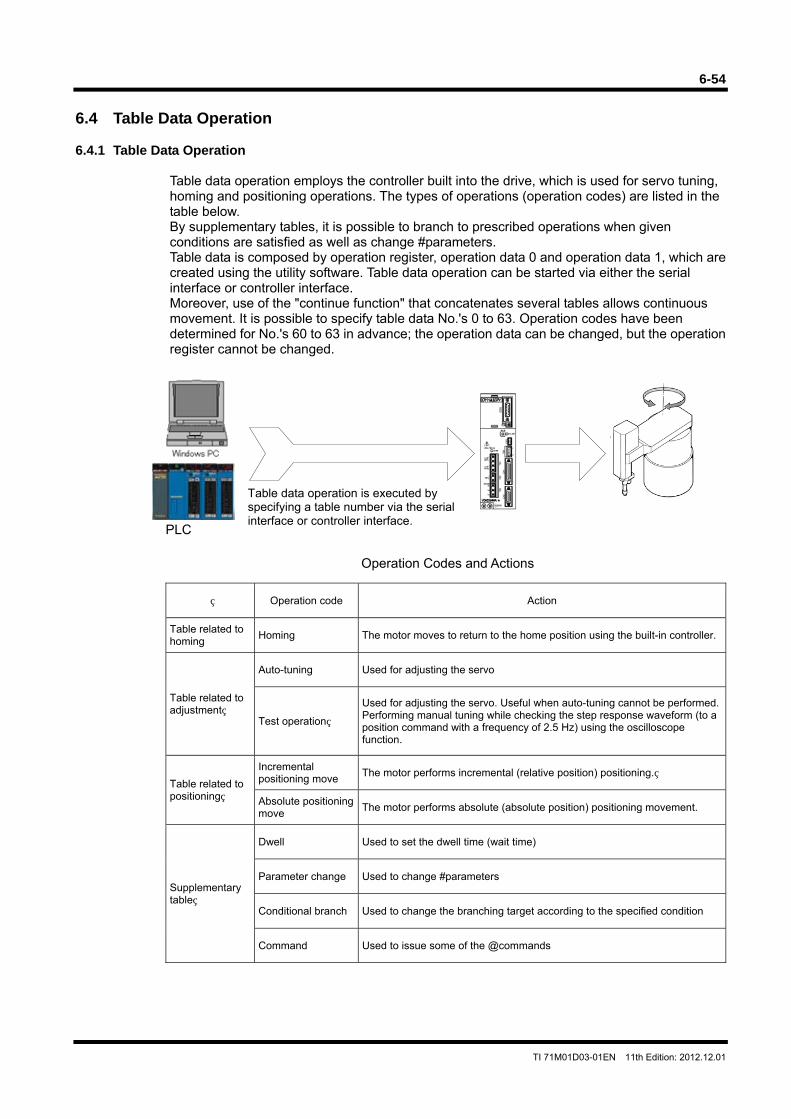
6-54
TI 71M01D03-01EN 11th Edition: 2012.12.01
6.4 Table Data Operation 6.4.1 Table Data Operation
Table data operation employs the controller built into the drive, which is used for servo tuning, homing and positioning operations. The types of operations (operation codes) are listed in the table below. By supplementary tables, it is possible to branch to prescribed operations when given conditions are satisfied as well as change #parameters. Table data is composed by operation register, operation data 0 and operation data 1, which are created using the utility software. Table data operation can be started via either the serial interface or controller interface. Moreover, use of the "continue function" that concatenates several tables allows continuous movement. It is possible to specify table data No.'s 0 to 63. Operation codes have been determined for No.'s 60 to 63 in advance; the operation data can be changed, but the operation register cannot be changed.
Operation Codes and Actions
Operation code Action
Table related to homing
Homing The motor moves to return to the home position using the built-in controller.
Table related to adjustment
Auto-tuning Used for adjusting the servo
Test operation
Used for adjusting the servo. Useful when auto-tuning cannot be performed. Performing manual tuning while checking the step response waveform (to a position command with a frequency of 2.5 Hz) using the oscilloscope function.
Table related to positioning
Incremental positioning move
The motor performs incremental (relative position) positioning.
Absolute positioning move
The motor performs absolute (absolute position) positioning movement.
Supplementary table
Dwell Used to set the dwell time (wait time)
Parameter change Used to change #parameters
Conditional branch Used to change the branching target according to the specified condition
Command Used to issue some of the @commands
Table data operation is executed by specifying a table number via the serial interface or controller interface.
PLC
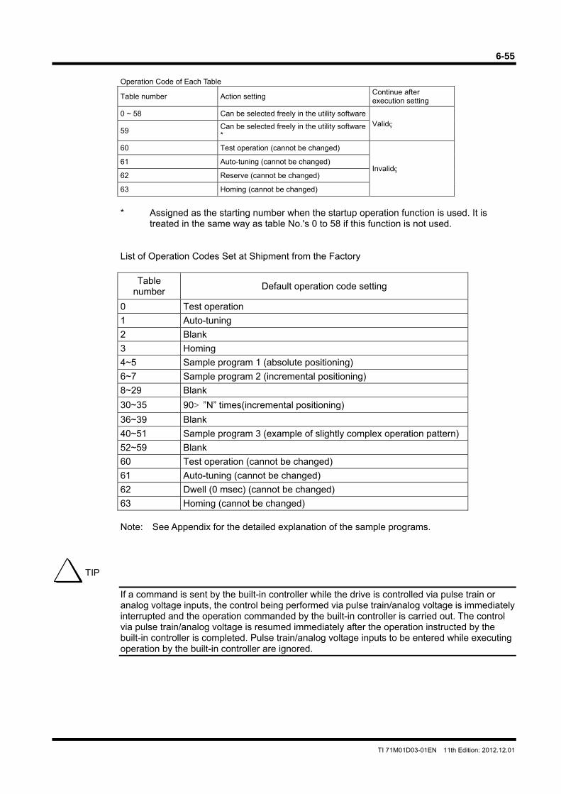
6-55
TI 71M01D03-01EN 11th Edition: 2012.12.01
Operation Code of Each Table
Table number Action setting Continue after execution setting
0 ~ 58 Can be selected freely in the utility softwareValid
59 Can be selected freely in the utility software *
60 Test operation (cannot be changed)
Invalid 61 Auto-tuning (cannot be changed)
62 Reserve (cannot be changed)
63 Homing (cannot be changed)
* Assigned as the starting number when the startup operation function is used. It is
treated in the same way as table No.'s 0 to 58 if this function is not used.
List of Operation Codes Set at Shipment from the Factory
Table number
Default operation code setting
0 Test operation
1 Auto-tuning
2 Blank
3 Homing
4~5 Sample program 1 (absolute positioning)
6~7 Sample program 2 (incremental positioning)
8~29 Blank
30~35 90°”N” times(incremental positioning)
36~39 Blank
40~51 Sample program 3 (example of slightly complex operation pattern)
52~59 Blank
60 Test operation (cannot be changed)
61 Auto-tuning (cannot be changed)
62 Dwell (0 msec) (cannot be changed)
63 Homing (cannot be changed)
Note: See Appendix for the detailed explanation of the sample programs.
If a command is sent by the built-in controller while the drive is controlled via pulse train or analog voltage inputs, the control being performed via pulse train/analog voltage is immediately interrupted and the operation commanded by the built-in controller is carried out. The control via pulse train/analog voltage is resumed immediately after the operation instructed by the built-in controller is completed. Pulse train/analog voltage inputs to be entered while executing operation by the built-in controller are ignored.
TIP
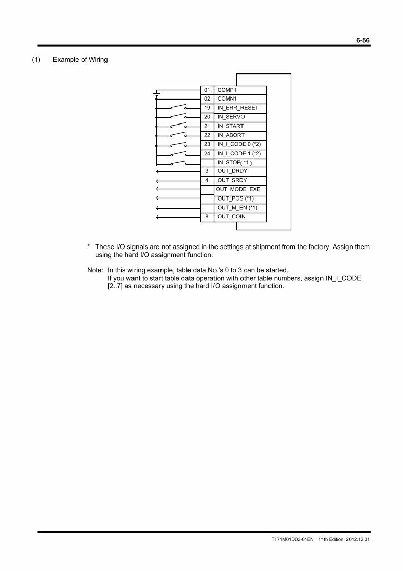
6-56
TI 71M01D03-01EN 11th Edition: 2012.12.01
(1) Example of Wiring
* These I/O signals are not assigned in the settings at shipment from the factory. Assign them using the hard I/O assignment function.
Note: In this wiring example, table data No.'s 0 to 3 can be started.
If you want to start table data operation with other table numbers, assign IN_I_CODE [2..7] as necessary using the hard I/O assignment function.
IN_STOP (*)
OUT_POS (*)
OUT_M_EN (*)
COMP1
COMN1
IN_START
IN_ABORT
IN_I_CODE 0 (*2)
IN_I_CODE 1 (*2)
IN_SERVO
IN_ERR_RESET
01
02
19
20
21
22
23
24
IN_STOP(*1)
OUT_M_EN (*1)
OUT_POS (*1)
OUT_COIN
OUT_DRDY
OUT_SRDY
OUT_MODE_EXE
8
3
4
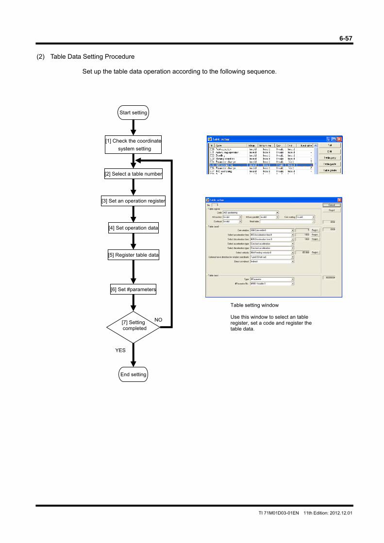
6-57
TI 71M01D03-01EN 11th Edition: 2012.12.01
(2) Table Data Setting Procedure
Set up the table data operation according to the following sequence.
Table setting window Use this window to select an table register, set a code and register the table data.
[1] Check the coordinate
system setting
Start setting
[2] Select a table number
[3] Set an operation register
[4] Set operation data
[5] Register table data
[6] Set #parameters
[7] Setting completed
End setting
YES
NO
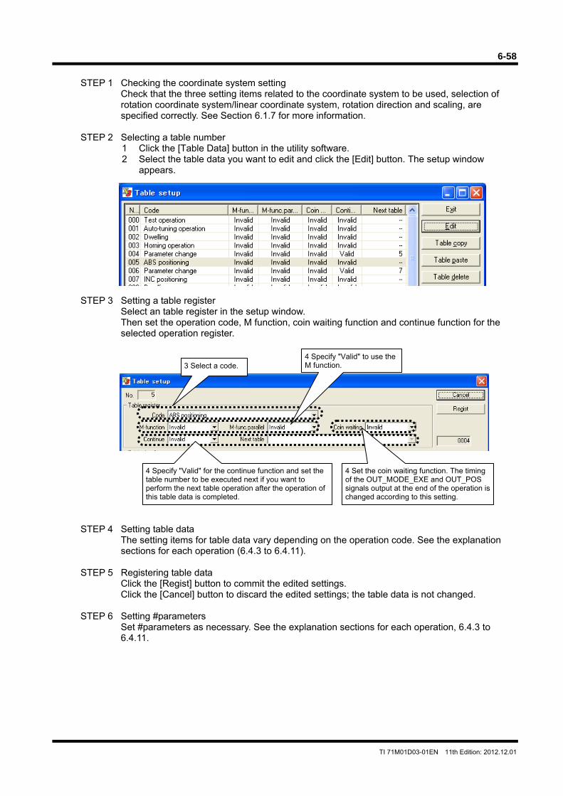
6-58
TI 71M01D03-01EN 11th Edition: 2012.12.01
STEP 1 Checking the coordinate system setting
Check that the three setting items related to the coordinate system to be used, selection of rotation coordinate system/linear coordinate system, rotation direction and scaling, are specified correctly. See Section 6.1.7 for more information.
STEP 2 Selecting a table number
1 Click the [Table Data] button in the utility software. 2 Select the table data you want to edit and click the [Edit] button. The setup window
appears.
STEP 3 Setting a table register Select an table register in the setup window. Then set the operation code, M function, coin waiting function and continue function for the selected operation register.
STEP 4 Setting table data The setting items for table data vary depending on the operation code. See the explanation sections for each operation (6.4.3 to 6.4.11).
STEP 5 Registering table data
Click the [Regist] button to commit the edited settings. Click the [Cancel] button to discard the edited settings; the table data is not changed.
STEP 6 Setting #parameters
Set #parameters as necessary. See the explanation sections for each operation, 6.4.3 to 6.4.11.
4 Specify "Valid" for the continue function and set the table number to be executed next if you want to perform the next table operation after the operation of this table data is completed.
4 Set the coin waiting function. The timing of the OUT_MODE_EXE and OUT_POS signals output at the end of the operation is changed according to this setting.
4 Specify "Valid" to use the M function.3 Select a code.
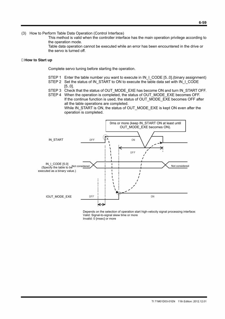
6-59
TI 71M01D03-01EN 11th Edition: 2012.12.01
(3) How to Perform Table Data Operation (Control Interface)
This method is valid when the controller interface has the main operation privilege according to the operation mode. Table data operation cannot be executed while an error has been encountered in the drive or the servo is turned off.
How to Start up
Complete servo tuning before starting the operation. STEP 1 Enter the table number you want to execute in IN_I_CODE [5..0].(binary assignment) STEP 2 Set the status of IN_START to ON to execute the table data set with IN_I_CODE
[5..0]. STEP 3 Check that the status of OUT_MODE_EXE has become ON and turn IN_START OFF. STEP 4 When the operation is completed, the status of OUT_MODE_EXE becomes OFF.
If the continue function is used, the status of OUT_MODE_EXE becomes OFF after all the table operations are completed. While IN_START is ON, the status of OUT_MODE_EXE is kept ON even after the operation is completed.
OFF ON
OFF
OFF ON
IN_I_CODE [5.0] (Specify the table to be
executed as a binary value.)
Depends on the selection of operation start high-velocity signal processing interface:Valid: Signal-to-signal skew time or more Invalid: 0 [msec] or more
Not considered
0ms or more (keep IN_START ON at least until OUT_MODE_EXE becomes ON).
Not considered
IN_START
IOUT_MODE_EXE
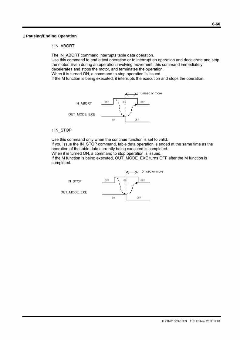
6-60
TI 71M01D03-01EN 11th Edition: 2012.12.01
Pausing/Ending Operation
IN_ABORT The IN_ABORT command interrupts table data operation. Use this command to end a test operation or to interrupt an operation and decelerate and stop the motor. Even during an operation involving movement, this command immediately decelerates and stops the motor, and terminates the operation. When it is turned ON, a command to stop operation is issued. If the M function is being executed, it interrupts the execution and stops the operation.
IN_STOP Use this command only when the continue function is set to valid. If you issue the IN_STOP command, table data operation is ended at the same time as the operation of the table data currently being executed is completed. When it is turned ON, a command to stop operation is issued. If the M function is being executed, OUT_MODE_EXE turns OFF after the M function is completed.
OFFOFF
OFF
ON
ON
0msec or more
IN_ABORT
OUT_MODE_EXE
ON
ON OFF
OFFOFF
0msec or more
IN_STOP
OUT_MODE_EXE
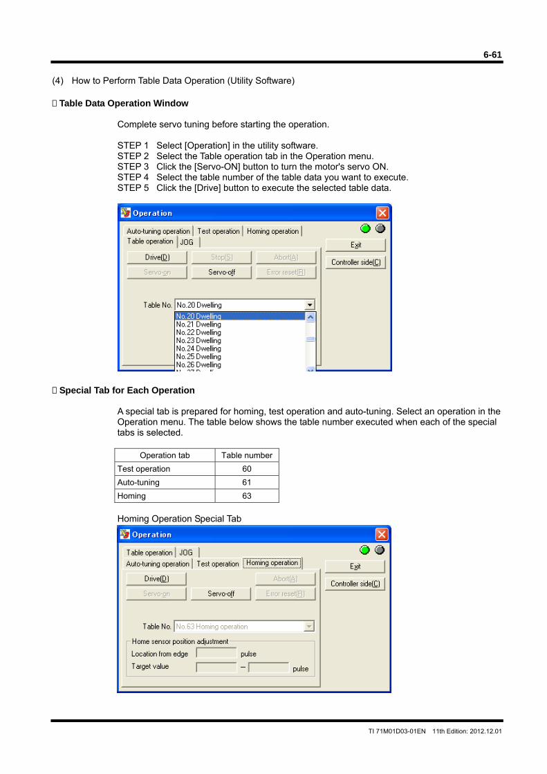
6-61
TI 71M01D03-01EN 11th Edition: 2012.12.01
(4) How to Perform Table Data Operation (Utility Software) Table Data Operation Window
Complete servo tuning before starting the operation. STEP 1 Select [Operation] in the utility software. STEP 2 Select the Table operation tab in the Operation menu. STEP 3 Click the [Servo-ON] button to turn the motor's servo ON. STEP 4 Select the table number of the table data you want to execute. STEP 5 Click the [Drive] button to execute the selected table data.
Special Tab for Each Operation
A special tab is prepared for homing, test operation and auto-tuning. Select an operation in the Operation menu. The table below shows the table number executed when each of the special tabs is selected.
Operation tab Table number
Test operation 60
Auto-tuning 61
Homing 63
Homing Operation Special Tab
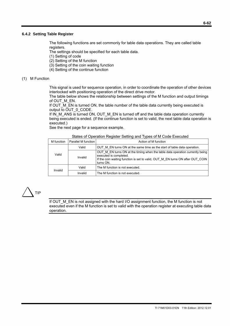
6-62
TI 71M01D03-01EN 11th Edition: 2012.12.01
6.4.2 Setting Table Register
The following functions are set commonly for table data operations. They are called table registers. The settings should be specified for each table data. (1) Setting of code (2) Setting of the M function (3) Setting of the coin waiting function (4) Setting of the continue function
(1) M Function
This signal is used for sequence operation, in order to coordinate the operation of other devices interlocked with positioning operation of the direct drive motor. The table below shows the relationship between settings of the M function and output timings of OUT_M_EN. If OUT_M_EN is turned ON, the table number of the table data currently being executed is output to OUT_0_CODE. If IN_M_ANS is turned ON, OUT_M_EN is turned off and the table data operation currently being executed is ended. (If the continue function is set to valid, the next table data operation is executed.) See the next page for a sequence example.
States of Operation Register Setting and Types of M Code Executed M function Parallel M function Action of M function
Valid
Valid OUT_M_EN turns ON at the same time as the start of table data operation.
Invalid
OUT_M_EN turns ON at the timing when the table data operation currently being executed is completed. If the coin waiting function is set to valid, OUT_M_EN turns ON after OUT_COIN turns ON.
Invalid Valid The M function is not executed.
Invalid The M function is not executed.
If OUT_M_EN is not assigned with the hard I/O assignment function, the M function is not executed even if the M function is set to valid with the operation register at executing table data operation.
TIP
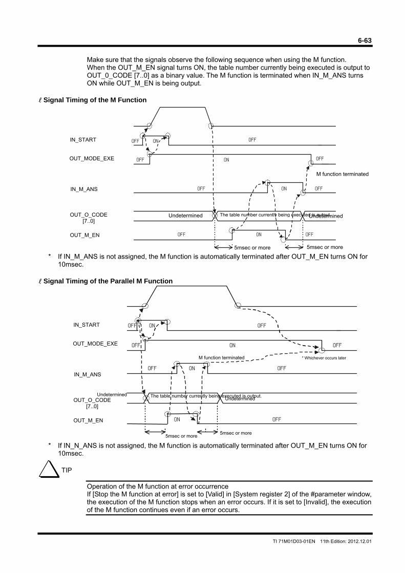
6-63
TI 71M01D03-01EN 11th Edition: 2012.12.01
Make sure that the signals observe the following sequence when using the M function. When the OUT_M_EN signal turns ON, the table number currently being executed is output to OUT_0_CODE [7..0] as a binary value. The M function is terminated when IN_M_ANS turns ON while OUT_M_EN is being output.
Signal Timing of the M Function
* If IN_M_ANS is not assigned, the M function is automatically terminated after OUT_M_EN turns ON for 10msec.
Signal Timing of the Parallel M Function
* If IN_N_ANS is not assigned, the M function is automatically terminated after OUT_M_EN turns ON for 10msec.
Operation of the M function at error occurrence If [Stop the M function at error] is set to [Valid] in [System register 2] of the #parameter window, the execution of the M function stops when an error occurs. If it is set to [Invalid], the execution of the M function continues even if an error occurs.
TIP
Undetermined
OFF OFFON
OFF OFFON
OFF OFFON
OFFON
Undetermined
5msec or more5msec or more
M function terminated
The table number currently being executed is output.
* Whichever occurs later
IN_START
OUT_MODE_EXE
IN_M_ANS
OUT_O_CODE[7..0]
OUT_M_EN
ONOFF OFF
ONOFF OFF
OFF OFFON
OFF OFFON
UndeterminedUndetermined
5msec or more
M function terminated
The table number currently being executed is output.
5msec or more
IN_START
OUT_MODE_EXE
IN_M_ANS
OUT_O_CODE[7..0]
OUT_M_EN
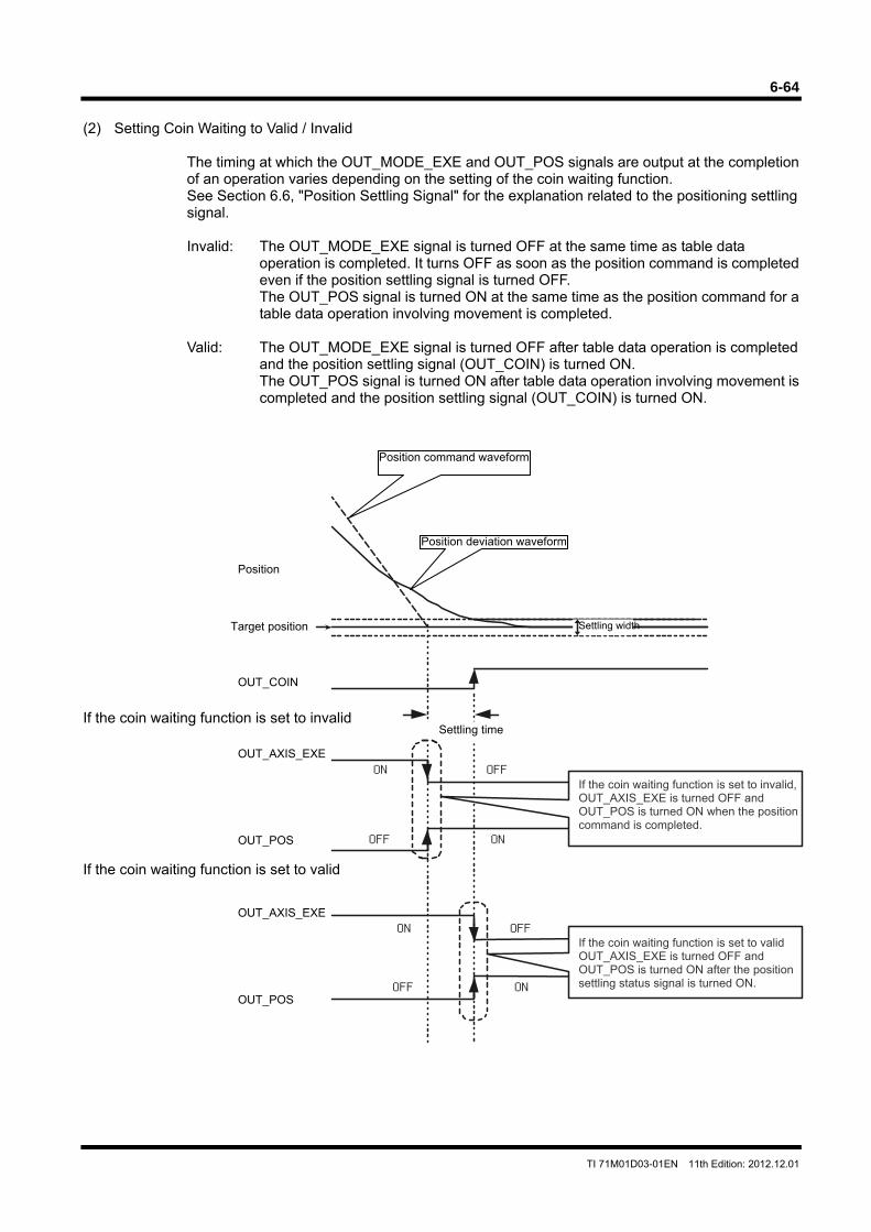
6-64
TI 71M01D03-01EN 11th Edition: 2012.12.01
OFFON
OFFON
OFF
OFF
ON
ON
(2) Setting Coin Waiting to Valid / Invalid
The timing at which the OUT_MODE_EXE and OUT_POS signals are output at the completion of an operation varies depending on the setting of the coin waiting function. See Section 6.6, "Position Settling Signal" for the explanation related to the positioning settling signal. Invalid: The OUT_MODE_EXE signal is turned OFF at the same time as table data
operation is completed. It turns OFF as soon as the position command is completed even if the position settling signal is turned OFF. The OUT_POS signal is turned ON at the same time as the position command for a table data operation involving movement is completed.
Valid: The OUT_MODE_EXE signal is turned OFF after table data operation is completed
and the position settling signal (OUT_COIN) is turned ON. The OUT_POS signal is turned ON after table data operation involving movement is completed and the position settling signal (OUT_COIN) is turned ON.
If the coin waiting function is set to invalid If the coin waiting function is set to valid
Settling time
Position command waveform
Position
If the coin waiting function is set to invalid, OUT_AXIS_EXE is turned OFF and OUT_POS is turned ON when the position command is completed.
If the coin waiting function is set to valid OUT_AXIS_EXE is turned OFF and OUT_POS is turned ON after the position settling status signal is turned ON.
Position deviation waveform
Target position Settling width
OUT_COIN
OUT_AXIS_EXE
OUT_POS
OUT_AXIS_EXE
OUT_POS

6-65
TI 71M01D03-01EN 11th Edition: 2012.12.01
(3) Continue Function
This function is used to perform two or more table data operations consecutively. In the table setting window, enable [Continue after execution] and select the table numbers to be executed subsequently from [Next table number]. When operating using the continue function, the OUT_MODE_EXE signal is not turned OFF when the operation switches to the next table data.
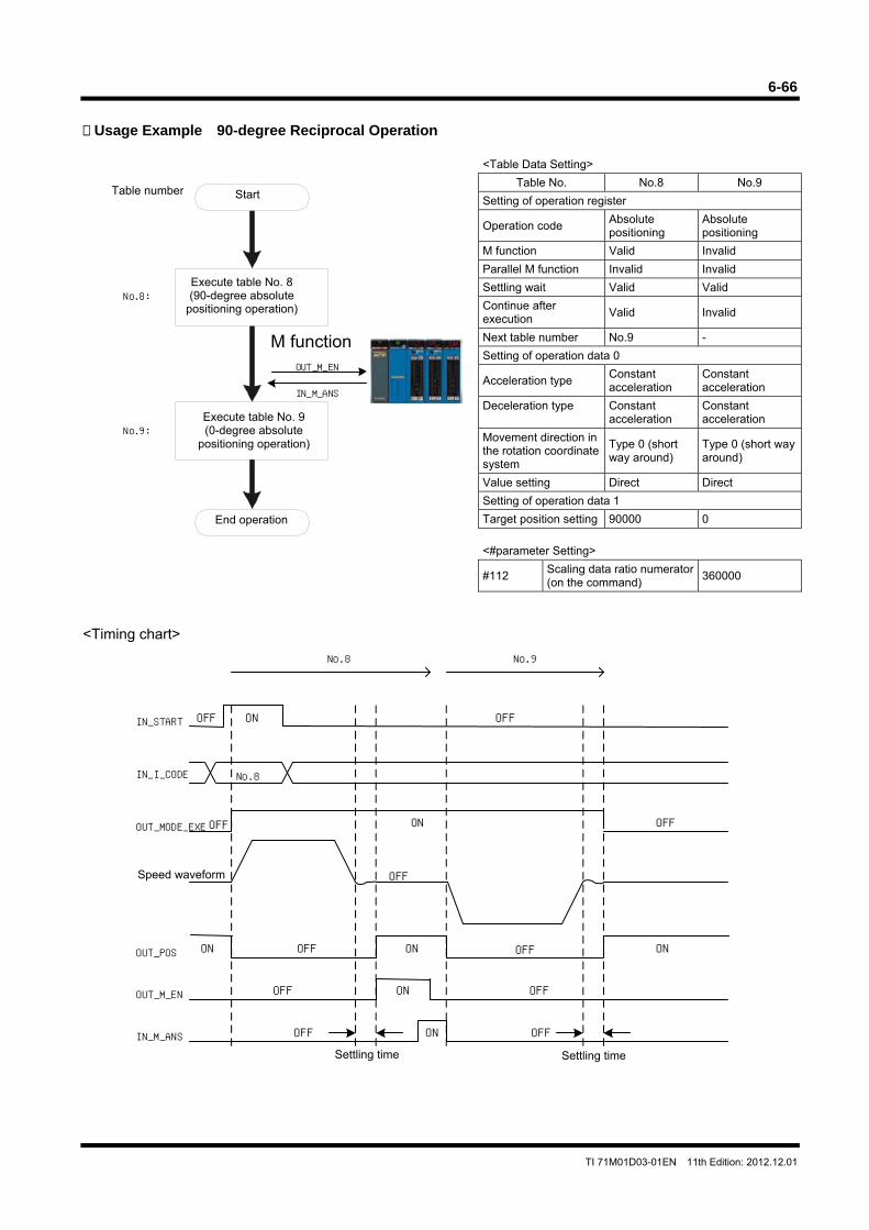
6-66
TI 71M01D03-01EN 11th Edition: 2012.12.01
No.8:
No.9:
OUT_M_EN
IN_M_ANS
Usage Example 90-degree Reciprocal Operation
<Table Data Setting>
Table No. No.8 No.9
Setting of operation register
Operation code Absolute positioning
Absolute positioning
M function Valid Invalid
Parallel M function Invalid Invalid
Settling wait Valid Valid
Continue after execution
Valid Invalid
Next table number No.9 -
Setting of operation data 0
Acceleration type Constant acceleration
Constant acceleration
Deceleration type Constant acceleration
Constant acceleration
Movement direction in the rotation coordinate system
Type 0 (short way around)
Type 0 (short way around)
Value setting Direct Direct
Setting of operation data 1
Target position setting 90000 0
<#parameter Setting>
#112 Scaling data ratio numerator (on the command)
360000
<Timing chart>
Speed waveform
Settling time Settling time
Table number
M function
Start
Execute table No. 8 (90-degree absolute
positioning operation)
Execute table No. 9 (0-degree absolute
positioning operation)
End operation
I N_S TAR T
O UT_ M_E N
I N_M _AN S
OUT_POS
OUT_MODE_EXE
No.8IN_I_CODE
OFF ON
OFF
ON
OFF
OFF OFF
OFF
ON ON
OFF
OFF
OFF
ON
OFF OFF
ON
ON
No.8 No.9
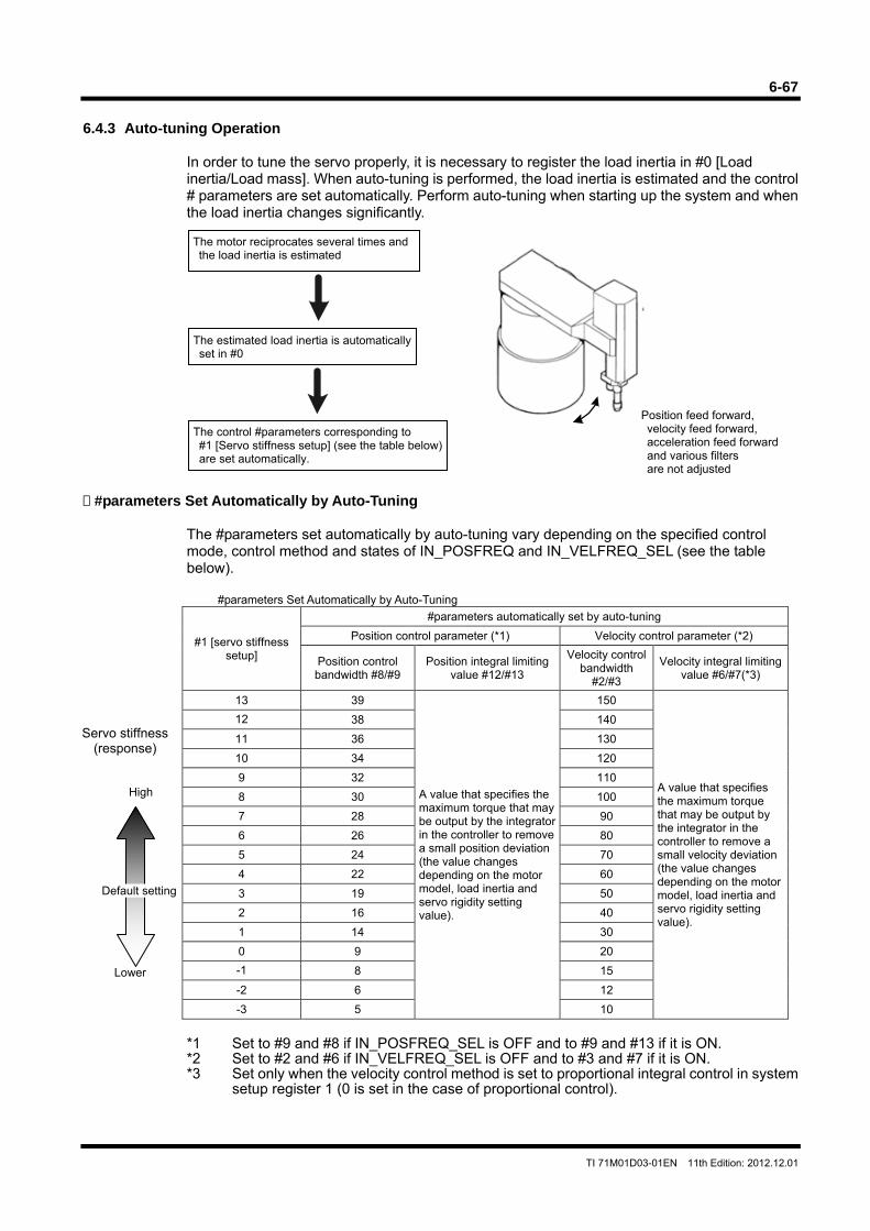
6-67
TI 71M01D03-01EN 11th Edition: 2012.12.01
6.4.3 Auto-tuning Operation
In order to tune the servo properly, it is necessary to register the load inertia in #0 [Load inertia/Load mass]. When auto-tuning is performed, the load inertia is estimated and the control # parameters are set automatically. Perform auto-tuning when starting up the system and when the load inertia changes significantly.
#parameters Set Automatically by Auto-Tuning
The #parameters set automatically by auto-tuning vary depending on the specified control mode, control method and states of IN_POSFREQ and IN_VELFREQ_SEL (see the table below).
#parameters Set Automatically by Auto-Tuning
#1 [servo stiffness setup]
#parameters automatically set by auto-tuning
Position control parameter (*1) Velocity control parameter (*2)
Position control bandwidth #8/#9
Position integral limiting value #12/#13
Velocity control bandwidth
#2/#3
Velocity integral limiting value #6/#7(*3)
13 39
A value that specifies the maximum torque that may be output by the integrator in the controller to remove a small position deviation (the value changes depending on the motor model, load inertia and servo rigidity setting value).
150
A value that specifies the maximum torque that may be output by the integrator in the controller to remove a small velocity deviation (the value changes depending on the motor model, load inertia and servo rigidity setting value).
12 38 140
11 36 130
10 34 120
9 32 110
8 30 100
7 28 90
6 26 80
5 24 70
4 22 60
3 19 50
2 16 40
1 14 30
0 9 20
-1 8 15
-2 6 12
-3 5 10
*1 Set to #9 and #8 if IN_POSFREQ_SEL is OFF and to #9 and #13 if it is ON. *2 Set to #2 and #6 if IN_VELFREQ_SEL is OFF and to #3 and #7 if it is ON. *3 Set only when the velocity control method is set to proportional integral control in system
setup register 1 (0 is set in the case of proportional control).
The motor reciprocates several times and the load inertia is estimated
The estimated load inertia is automatically set in #0
The control #parameters corresponding to #1 [Servo stiffness setup] (see the table below) are set automatically.
Position feed forward, velocity feed forward, acceleration feed forward and various filters are not adjusted
Servo stiffness (response)
Lower
High
Default setting
6-68
TI 71M01D03-01EN 11th Edition: 2012.12.01
(1) How to Set Auto-Tuning Operation
Set the data according to the flowchart showing the procedure for creating table data in Section 6.4.1, "Table Data Operation." See the following for how to set operation data and #parameters, corresponding to steps 4 and 6 in the flowchart.
Setting Operation Data
No operation data is used for the auto-tuning operation
Setting #parameters Related to Auto-tuning
Setting Auto-tuning Operation Width STEP 1 Select [Data Management], [#parameter] and then [Function parameter] from the
utility software. STEP 2 Select the Auto-tuning tab from the Parameter by Function window. STEP 3 Check that the auto-tuning operation width is sufficiently narrower than the movable
range required for normal operation. STEP 4 Set and register #parameters.
Selecting Control Mode and Control Method The #parameters set by auto-tuning vary depending on the control mode and control method. Perform auto-tuning after registering the control mode and control method used with the corresponding #parameters. STEP 1 Select [#parameter] and then [Register parameter ] in the utility software. STEP 2 Select [System setup register 1]. STEP 3 Select a control mode. STEP 4 Select a control method with [Position control method setting]. STEP 5 Select a control method with [Velocity control method setting]. STEP 6 Set and register #parameters.
Setting of Other #parameters See the table on the next page for the #parameters related to auto-tuning. Change the setup values of the #parameters as necessary.
The operation direction of auto-tuning is the + direction with respect to the position before starting the operation. Nonetheless, secure sufficient space in the - direction as well before starting the operation.
Make the auto-tuning operation width narrower if you cannot secure a sufficient movable range. Note, however, that the inertia estimation accuracy may become lower if the auto-tuning operation width is made narrower.
If you cannot perform auto-tuning, calculate the inertia moment of the load, and enter the inertial moment value directly in the corresponding #parameter (#0).
WARNING
CAUTION
TIP
6-69
TI 71M01D03-01EN 11th Edition: 2012.12.01
#parameters Related to Auto-tuning Operation
#parameter No. #parameter name Description
#51 Operation range under auto-tuning mode
This parameter specifies the auto-tuning operation width. This parameter can be used without changing the initial value under normal circumstances. Make this value larger (two to five times) if the auto-tuning is not completed normally, and perform the auto-tuning again. At shipment from the factory, this parameter is set to a value equivalent to 2% of the rated velocity. Example: If the rated velocity is 2rps 2 x 0.02 x 360 degrees → Equivalent to 14.4 degrees
#52 Maximum acceleration/deceleration time under auto-tuning
This parameter can be used without changing the initial value set at shipment from the factory under normal circumstances.
#53 Initial acceleration/deceleration time under auto-tuning
This parameter can be used without changing the initial value set at shipment from the factory under normal circumstances.
#1 Servo stiffness setup This parameter specifies the servo rigidity after the auto-tuning operation. Make this value smaller if the auto-tuning is not completed normally, or if oscillation or instability occurs.
#54 Repetition number for auto-tuning This parameter can be used without changing the initial value set at shipment from the factory (#54 = 6) under normal circumstances.
#parameters Set Automatically after Executing Auto-tuning Operation
#parameter No. #parameter name Description
#0 Load inertia/Load mass The load inertia value is set automatically in this parameter after auto-tuning. If the load inertia value is known, it is all right to write the load inertia value directly in this #parameter without performing auto-tuning.
#2 or #3 Velocity control bandwidth #1 or Velocity control bandwidth #2
This parameter is set automatically after auto-tuning. The velocity control band frequency is set automatically in the #parameter selected by IN_VELFREQ_SEL according to the setting status of #1 [servo stiffness setup].
#8 or #9 Position control bandwidth #1 or Position control bandwidth #2
This parameter is set automatically after auto-tuning. The position control band frequency is set automatically in the #parameter selected by IN_POSFREQ_SEL according to the setting status of #1 [servo stiffness setup].
#6 or #7 Velocity integral limiting value #1 or Velocity integral limiting value #2
This #parameter is used only when the velocity control method is set to proportional integral control in system setup register 1. It is automatically set in the #parameter selected by IN_VELFREQ_SEL when you perform auto-tuning. The value specifies the maximum torque that may be output by the integrator in the controller to remove a small velocity deviation (the value varies depending on the motor model, load inertia and servo stiffness setup value).
#12 or #13 Position integral limiting value #1 or Position integral limiting value #2
This limiter restricts the amount of position integration of the position control loop. This #parameter is used only when the control mode is set to position control and the velocity control method is set to proportional control in system setup register 1. It is automatically set in the #parameter selected by IN_POSFREQ_SEL when you perform auto-tuning. The value specifies the maximum torque that may be output by the integrator in the controller to remove a small velocity deviation (the value varies depending on the motor model, load inertia and servo stiffness setup value).
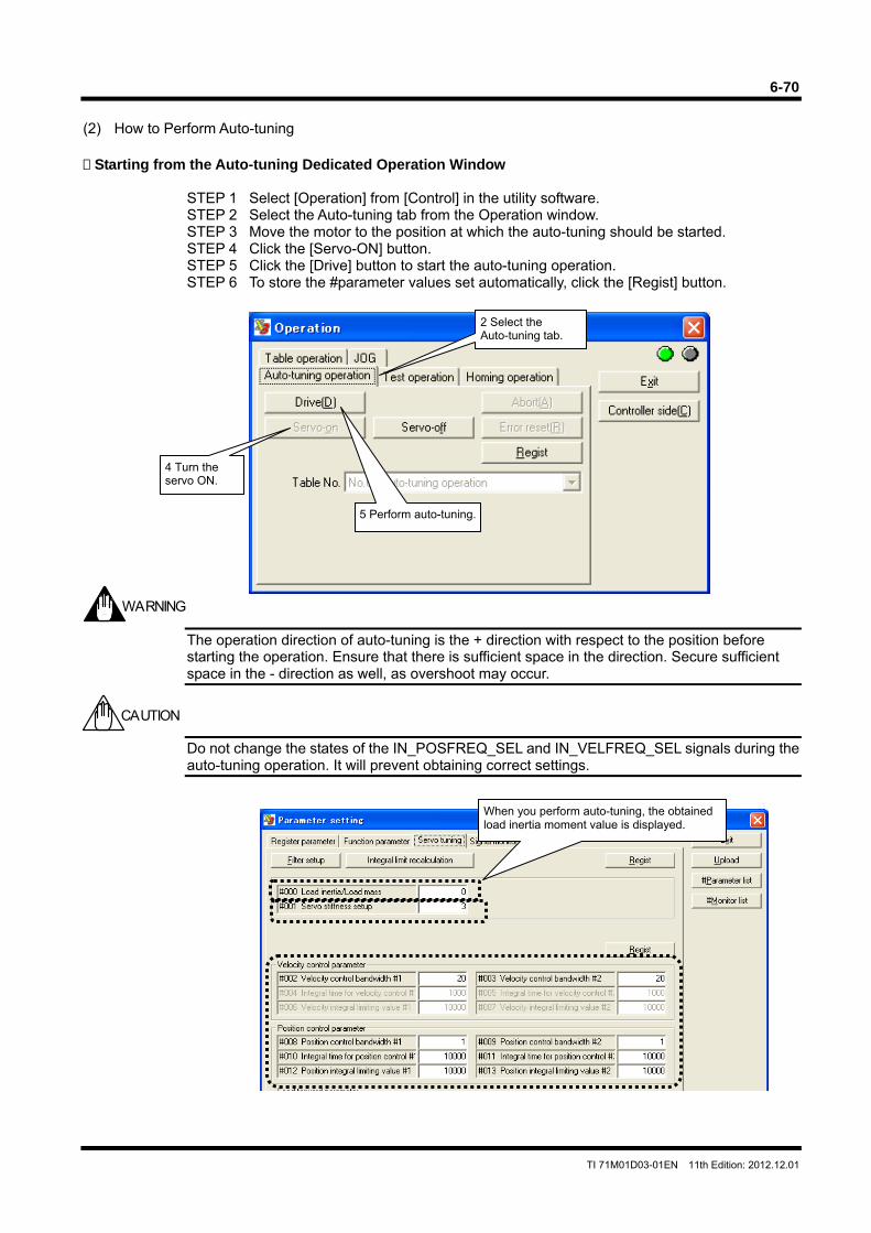
6-70
TI 71M01D03-01EN 11th Edition: 2012.12.01
(2) How to Perform Auto-tuning Starting from the Auto-tuning Dedicated Operation Window
STEP 1 Select [Operation] from [Control] in the utility software. STEP 2 Select the Auto-tuning tab from the Operation window. STEP 3 Move the motor to the position at which the auto-tuning should be started. STEP 4 Click the [Servo-ON] button. STEP 5 Click the [Drive] button to start the auto-tuning operation. STEP 6 To store the #parameter values set automatically, click the [Regist] button.
The operation direction of auto-tuning is the + direction with respect to the position before starting the operation. Ensure that there is sufficient space in the direction. Secure sufficient space in the - direction as well, as overshoot may occur.
Do not change the states of the IN_POSFREQ_SEL and IN_VELFREQ_SEL signals during the auto-tuning operation. It will prevent obtaining correct settings.
2 Select the Auto-tuning tab.
4 Turn the servo ON.
5 Perform auto-tuning.
WARNING
CAUTION
When you perform auto-tuning, the obtained load inertia moment value is displayed.
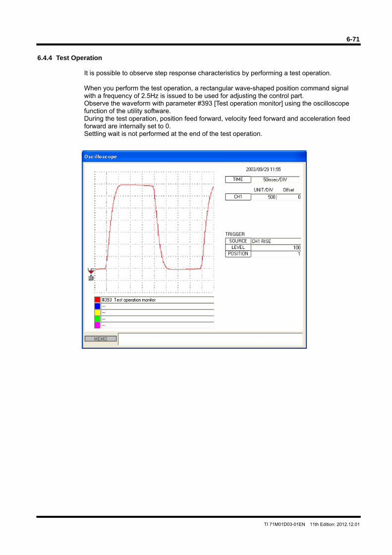
6-71
TI 71M01D03-01EN 11th Edition: 2012.12.01
6.4.4 Test Operation
It is possible to observe step response characteristics by performing a test operation. When you perform the test operation, a rectangular wave-shaped position command signal with a frequency of 2.5Hz is issued to be used for adjusting the control part. Observe the waveform with parameter #393 [Test operation monitor] using the oscilloscope function of the utility software. During the test operation, position feed forward, velocity feed forward and acceleration feed forward are internally set to 0. Settling wait is not performed at the end of the test operation.
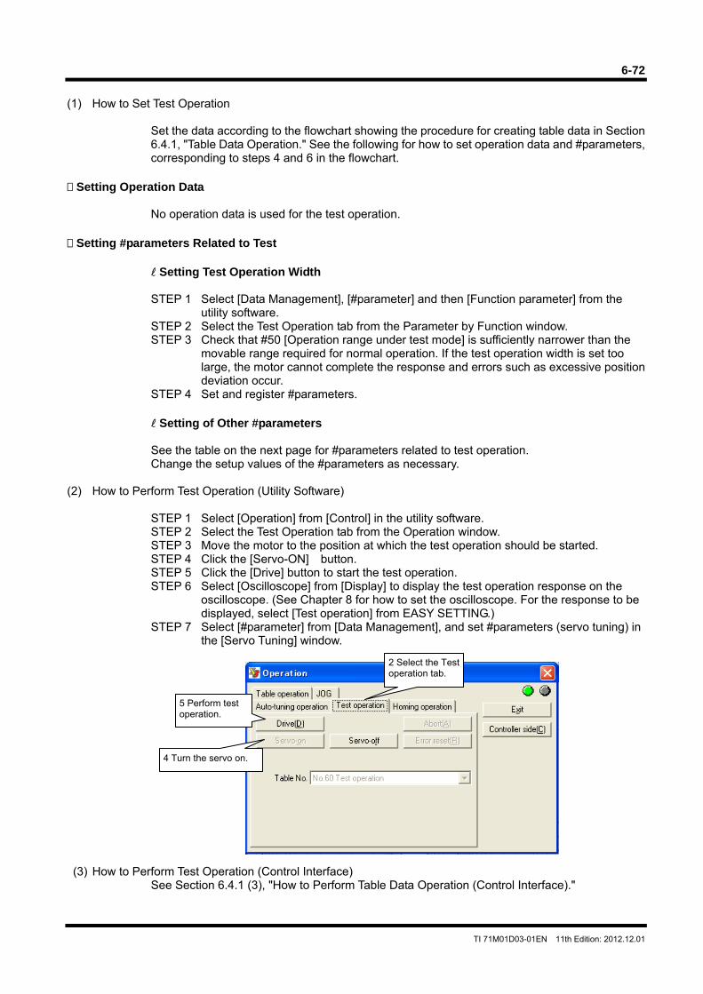
6-72
TI 71M01D03-01EN 11th Edition: 2012.12.01
(1) How to Set Test Operation
Set the data according to the flowchart showing the procedure for creating table data in Section 6.4.1, "Table Data Operation." See the following for how to set operation data and #parameters, corresponding to steps 4 and 6 in the flowchart.
Setting Operation Data
No operation data is used for the test operation.
Setting #parameters Related to Test
Setting Test Operation Width
STEP 1 Select [Data Management], [#parameter] and then [Function parameter] from the
utility software. STEP 2 Select the Test Operation tab from the Parameter by Function window. STEP 3 Check that #50 [Operation range under test mode] is sufficiently narrower than the
movable range required for normal operation. If the test operation width is set too large, the motor cannot complete the response and errors such as excessive position deviation occur.
STEP 4 Set and register #parameters.
Setting of Other #parameters
See the table on the next page for #parameters related to test operation. Change the setup values of the #parameters as necessary.
(2) How to Perform Test Operation (Utility Software)
STEP 1 Select [Operation] from [Control] in the utility software. STEP 2 Select the Test Operation tab from the Operation window. STEP 3 Move the motor to the position at which the test operation should be started. STEP 4 Click the [Servo-ON] button. STEP 5 Click the [Drive] button to start the test operation. STEP 6 Select [Oscilloscope] from [Display] to display the test operation response on the
oscilloscope. (See Chapter 8 for how to set the oscilloscope. For the response to be displayed, select [Test operation] from EASY SETTING.)
STEP 7 Select [#parameter] from [Data Management], and set #parameters (servo tuning) in the [Servo Tuning] window.
(3) How to Perform Test Operation (Control Interface)
See Section 6.4.1 (3), "How to Perform Table Data Operation (Control Interface)."
2 Select the Test operation tab.
4 Turn the servo on.
5 Perform test operation.
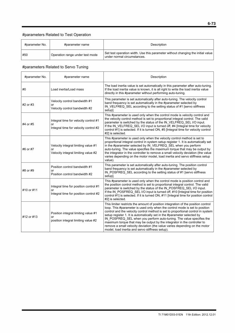
6-73
TI 71M01D03-01EN 11th Edition: 2012.12.01
#parameters Related to Test Operation
#parameter No. #parameter name Description
#50 Operation range under test mode Set test operation width. Use this parameter without changing the initial value under normal circumstances.
#parameters Related to Servo Tuning
#parameter No. #parameter name Description
#0 Load inertia/Load mass The load inertia value is set automatically in this parameter after auto-tuning. If the load inertia value is known, it is all right to write the load inertia value directly in this #parameter without performing auto-tuning.
#2 or #3 Velocity control bandwidth #1 or Velocity control bandwidth #2
This parameter is set automatically after auto-tuning. The velocity control band frequency is set automatically in the #parameter selected by IN_VELFREQ_SEL according to the setting status of #1 [servo stiffness setup].
#4 or #5 Integral time for velocity control #1 or Integral time for velocity control #2
This #parameter is used only when the control mode is velocity control and the velocity control method is set to proportional integral control. The valid parameter is switched by the status of the IN_VELFREQ_SEL I/O input. If the IN_VELFREQ_SEL I/O input is turned off, #4 [Integral time for velocity control #1] is selected. If it is turned ON, #5 [Integral time for velocity control #2] is selected.
#6 or #7 Velocity integral limiting value #1 or Velocity integral limiting value #2
This #parameter is used only when the velocity control method is set to proportional integral control in system setup register 1. It is automatically set in the #parameter selected by IN_VELFREQ_SEL when you perform auto-tuning. The value specifies the maximum torque that may be output by the integrator in the controller to remove a small velocity deviation (the value varies depending on the motor model, load inertia and servo stiffness setup value).
#8 or #9 Position control bandwidth #1 or Position control bandwidth #2
This parameter is set automatically after auto-tuning. The position control band frequency is set automatically in the #parameter selected by IN_POSFREQ_SEL according to the setting status of #1 [servo stiffness setup].
#10 or #11 Integral time for position control #1 or Integral time for position control #2
This #parameter is used only when the control mode is position control and the position control method is set to proportional integral control. The valid parameter is switched by the status of the IN_POSFREQ_SEL I/O input. If the IN_POSFREQ_SEL I/O input is turned off, #10 [Integral time for position control #1] is selected. If it is turned ON, #11 [Integral time for position control #2] is selected.
#12 or #13 Position integral limiting value #1 or position integral limiting value #2
This limiter restricts the amount of position integration of the position control loop. This #parameter is used only when the control mode is set to position control and the velocity control method is set to proportional control in system setup register 1. It is automatically set in the #parameter selected by IN_POSFREQ_SEL when you perform auto-tuning. The value specifies the maximum torque that may be output by the integrator in the controller to remove a small velocity deviation (the value varies depending on the motor model, load inertia and servo stiffness setup).
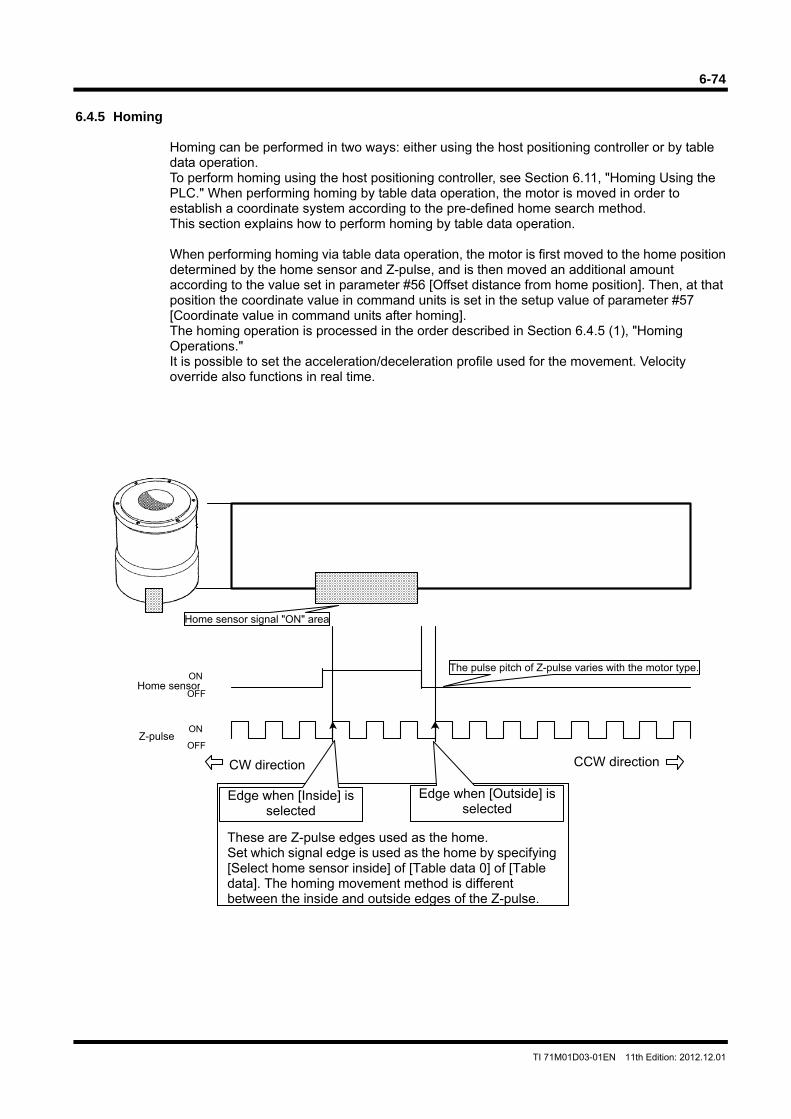
6-74
TI 71M01D03-01EN 11th Edition: 2012.12.01
6.4.5 Homing
Homing can be performed in two ways: either using the host positioning controller or by table data operation. To perform homing using the host positioning controller, see Section 6.11, "Homing Using the PLC." When performing homing by table data operation, the motor is moved in order to establish a coordinate system according to the pre-defined home search method. This section explains how to perform homing by table data operation. When performing homing via table data operation, the motor is first moved to the home position determined by the home sensor and Z-pulse, and is then moved an additional amount according to the value set in parameter #56 [Offset distance from home position]. Then, at that position the coordinate value in command units is set in the setup value of parameter #57 [Coordinate value in command units after homing]. The homing operation is processed in the order described in Section 6.4.5 (1), "Homing Operations." It is possible to set the acceleration/deceleration profile used for the movement. Velocity override also functions in real time.
Home sensor
CCW directionCW direction
ON
OFF
Z-pulseON
OFF
Home sensor signal "ON" area
The pulse pitch of Z-pulse varies with the motor type.
These are Z-pulse edges used as the home. Set which signal edge is used as the home by specifying [Select home sensor inside] of [Table data 0] of [Table data]. The homing movement method is different between the inside and outside edges of the Z-pulse.
Edge when [Outside] is selected
Edge when [Inside] is selected
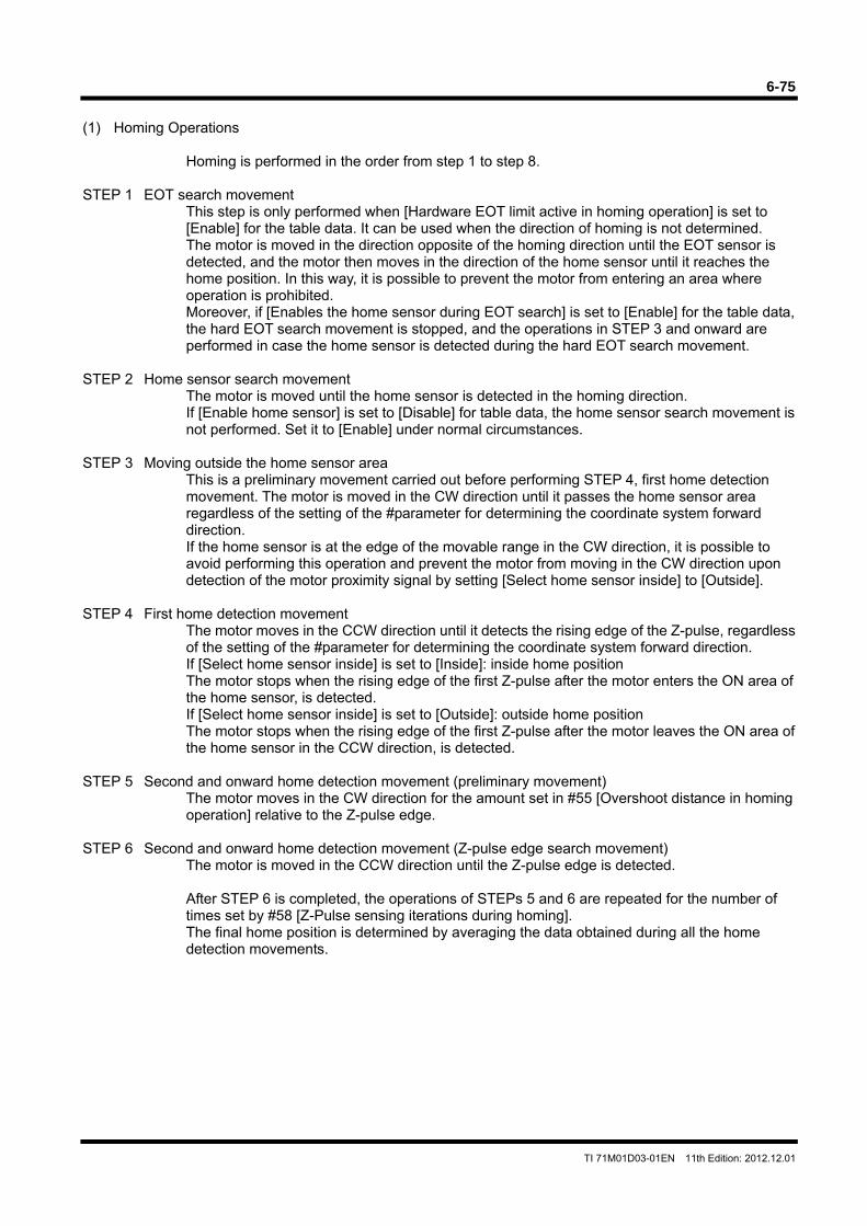
6-75
TI 71M01D03-01EN 11th Edition: 2012.12.01
(1) Homing Operations
Homing is performed in the order from step 1 to step 8. STEP 1 EOT search movement
This step is only performed when [Hardware EOT limit active in homing operation] is set to [Enable] for the table data. It can be used when the direction of homing is not determined. The motor is moved in the direction opposite of the homing direction until the EOT sensor is detected, and the motor then moves in the direction of the home sensor until it reaches the home position. In this way, it is possible to prevent the motor from entering an area where operation is prohibited. Moreover, if [Enables the home sensor during EOT search] is set to [Enable] for the table data, the hard EOT search movement is stopped, and the operations in STEP 3 and onward are performed in case the home sensor is detected during the hard EOT search movement.
STEP 2 Home sensor search movement
The motor is moved until the home sensor is detected in the homing direction. If [Enable home sensor] is set to [Disable] for table data, the home sensor search movement is not performed. Set it to [Enable] under normal circumstances.
STEP 3 Moving outside the home sensor area
This is a preliminary movement carried out before performing STEP 4, first home detection movement. The motor is moved in the CW direction until it passes the home sensor area regardless of the setting of the #parameter for determining the coordinate system forward direction. If the home sensor is at the edge of the movable range in the CW direction, it is possible to avoid performing this operation and prevent the motor from moving in the CW direction upon detection of the motor proximity signal by setting [Select home sensor inside] to [Outside].
STEP 4 First home detection movement
The motor moves in the CCW direction until it detects the rising edge of the Z-pulse, regardless of the setting of the #parameter for determining the coordinate system forward direction. If [Select home sensor inside] is set to [Inside]: inside home position The motor stops when the rising edge of the first Z-pulse after the motor enters the ON area of the home sensor, is detected. If [Select home sensor inside] is set to [Outside]: outside home position The motor stops when the rising edge of the first Z-pulse after the motor leaves the ON area of the home sensor in the CCW direction, is detected.
STEP 5 Second and onward home detection movement (preliminary movement)
The motor moves in the CW direction for the amount set in #55 [Overshoot distance in homing operation] relative to the Z-pulse edge.
STEP 6 Second and onward home detection movement (Z-pulse edge search movement)
The motor is moved in the CCW direction until the Z-pulse edge is detected.
After STEP 6 is completed, the operations of STEPs 5 and 6 are repeated for the number of times set by #58 [Z-Pulse sensing iterations during homing]. The final home position is determined by averaging the data obtained during all the home detection movements.
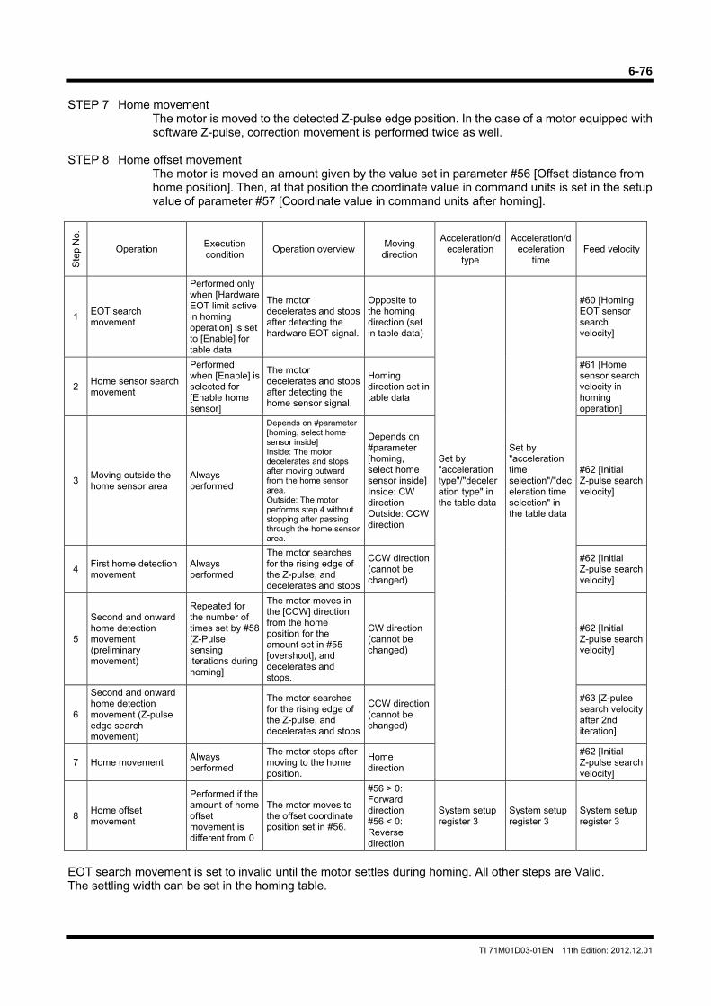
6-76
TI 71M01D03-01EN 11th Edition: 2012.12.01
STEP 7 Home movement
The motor is moved to the detected Z-pulse edge position. In the case of a motor equipped with software Z-pulse, correction movement is performed twice as well.
STEP 8 Home offset movement
The motor is moved an amount given by the value set in parameter #56 [Offset distance from home position]. Then, at that position the coordinate value in command units is set in the setup value of parameter #57 [Coordinate value in command units after homing].
Ste
p N
o.
Operation Execution condition
Operation overviewMoving
direction
Acceleration/deceleration
type
Acceleration/deceleration
time Feed velocity
1 EOT search movement
Performed only when [Hardware EOT limit active in homing operation] is set to [Enable] for table data
The motor decelerates and stops after detecting the hardware EOT signal.
Opposite to the homing direction (set in table data)
#60 [Homing EOT sensor search velocity]
2 Home sensor search movement
Performed when [Enable] is selected for [Enable home sensor]
The motor decelerates and stops after detecting the home sensor signal.
Homing direction set in table data
#61 [Home sensor search velocity in homing operation]
3 Moving outside the home sensor area
Always performed
Depends on #parameter [homing, select home sensor inside] Inside: The motor decelerates and stops after moving outward from the home sensor area. Outside: The motor performs step 4 without stopping after passing through the home sensor area.
Depends on #parameter [homing, select home sensor inside]Inside: CW direction Outside: CCW direction
Set by "acceleration type"/"deceleration type" in the table data
Set by "acceleration time selection"/"deceleration time selection" in the table data
#62 [Initial Z-pulse search velocity]
4 First home detection movement
Always performed
The motor searches for the rising edge of the Z-pulse, and decelerates and stops
CCW direction (cannot be changed)
#62 [Initial Z-pulse search velocity]
5
Second and onward home detection movement (preliminary movement)
Repeated for the number of times set by #58 [Z-Pulse sensing iterations during homing]
The motor moves in the [CCW] direction from the home position for the amount set in #55 [overshoot], and decelerates and stops.
CW direction (cannot be changed)
#62 [Initial Z-pulse search velocity]
6
Second and onward home detection movement (Z-pulse edge search movement)
The motor searches for the rising edge of the Z-pulse, and decelerates and stops
CCW direction (cannot be changed)
#63 [Z-pulse search velocity after 2nd iteration]
7 Home movement Always performed
The motor stops after moving to the home position.
Home direction
#62 [Initial Z-pulse search velocity]
8 Home offset movement
Performed if the amount of home offset movement is different from 0
The motor moves to the offset coordinate position set in #56.
#56 > 0: Forward direction #56 < 0: Reverse direction
System setup register 3
System setup register 3
System setup register 3
EOT search movement is set to invalid until the motor settles during homing. All other steps are Valid. The settling width can be set in the homing table.
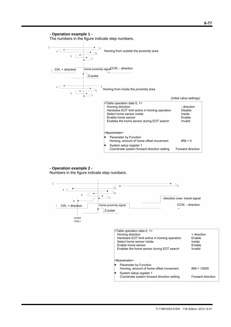
6-77
TI 71M01D03-01EN 11th Edition: 2012.12.01
2
43
34
7
56
56
7
←→
CW, + direction
Homing from outside the proximity area
Home proximity signal
Z-pulse
Homing from inside the proximity area
CCW, - direction
- Operation example 1 - The numbers in the figure indicate step numbers.
- Operation example 2 - Numbers in the figure indicate step numbers.
(Initial value settings)
<Table operation data 0, 1> Homing direction - direction Hardware EOT limit active in homing operation Disable Select home sensor inside Inside Enable home sensor Enable Enables the home sensor during EOT search Invalid
<#parameter> • Parameter by Function
Homing, amount of home offset movement #56 = 0 • System setup register 1
Coordinate system forward direction setting Forward direction
<Table operation data 0, 1> Homing direction + direction Hardware EOT limit active in homing operation Enable Select home sensor inside Inside Enable home sensor Enable Enables the home sensor during EOT search Invalid
<#parameter> • Parameter by Function
Homing, amount of home offset movement #56 = 10000 • System setup register 1
Coordinate system forward direction setting Forward direction
←
12
4
8
3
5
76
10000(#56)
→CW, + direction Home proximity signal
Z-pulse
- direction over- travel signal
CCW, - direction
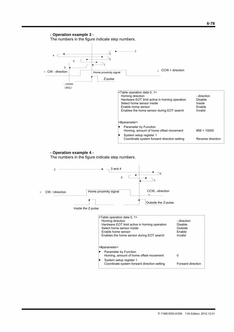
6-78
TI 71M01D03-01EN 11th Edition: 2012.12.01
2
4 3
56
87
→
-10000(#56)
← Home proximity signal
Z-pulse
CCW + direction CW - direction
25
67
←→
Home proximity signal
Inside the Z-pulse
Outside the Z-pulse
CW, +direction
3 and 4
CCW, -direction
- Operation example 3 - The numbers in the figure indicate step numbers.
- Operation example 4 - The numbers in the figure indicate step numbers.
<Table operation data 0, 1> Homing direction - direction Hardware EOT limit active in homing operation Disable Select home sensor inside Inside Enable home sensor Enable Enables the home sensor during EOT search Invalid
<#parameter> • Parameter by Function
Homing, amount of home offset movement #56 = 10000 • System setup register 1
Coordinate system forward direction setting Reverse direction
<Table operation data 0, 1> Homing direction - direction Hardware EOT limit active in homing operation Disable Select home sensor inside Outside Enable home sensor Enable Enables the home sensor during EOT search Invalid
<#parameter> • Parameter by Function
Homing, amount of home offset movement 0 • System setup register 1
Coordinate system forward direction setting Forward direction
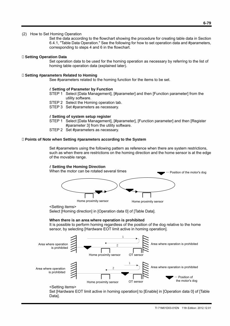
6-79
TI 71M01D03-01EN 11th Edition: 2012.12.01
(2) How to Set Homing Operation
Set the data according to the flowchart showing the procedure for creating table data in Section 6.4.1, "Table Data Operation." See the following for how to set operation data and #parameters, corresponding to steps 4 and 6 in the flowchart.
Setting Operation Data
Set operation data to be used for the homing operation as necessary by referring to the list of homing table operation data (explained later).
Setting #parameters Related to Homing
See #parameters related to the homing function for the items to be set. Setting of Parameter by Function STEP 1 Select [Data Management], [#parameter] and then [Function parameter] from the
utility software. STEP 2 Select the Homing operation tab. STEP 3 Set #parameters as necessary.
Setting of system setup register STEP 1 Select [Data Management], [#parameter], [Function parameter] and then [Register
#parameter 3] from the utility software. STEP 2 Set #parameters as necessary.
Points of Note when Setting #parameters according to the System
Set #parameters using the following pattern as reference when there are system restrictions, such as when there are restrictions on the homing direction and the home sensor is at the edge of the movable range.
Setting the Homing Direction When the motor can be rotated several times
<Setting items> Select [Homing direction] in [Operation data 0] of [Table Data]. When there is an area where operation is prohibited It is possible to perform homing regardless of the position of the dog relative to the home sensor, by selecting [Hardware EOT limit active in homing operation].
<Setting items> Set [Hardware EOT limit active in homing operation] to [Enable] in [Operation data 0] of [Table Data].
Home proximity sensor
Position of the motor's dog
Home proximity sensor
1
2
1
2
OT sensor
Area where operation is prohibited
Home proximity sensor OT sensor
Area where operation is prohibited
Area where operation is prohibited
Home proximity sensor
Position of the motor's dog
Area where operation is prohibited
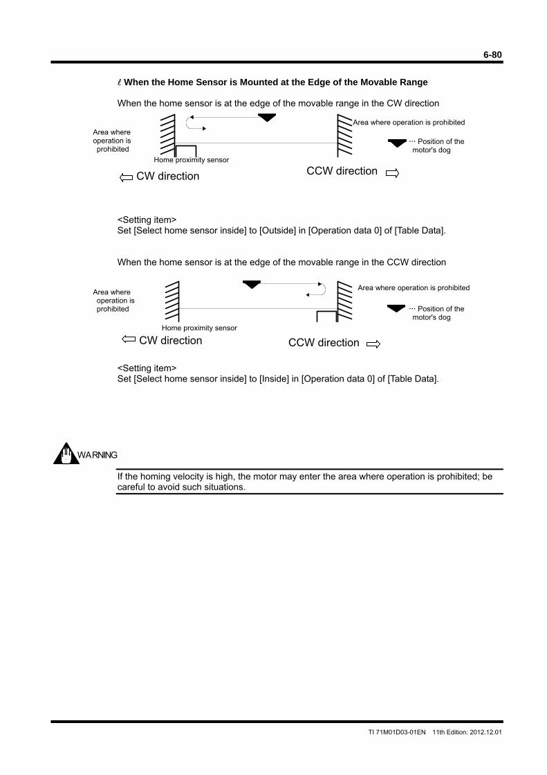
6-80
TI 71M01D03-01EN 11th Edition: 2012.12.01
CCW directionCW direction
Home proximity sensor
When the Home Sensor is Mounted at the Edge of the Movable Range When the home sensor is at the edge of the movable range in the CW direction
<Setting item> Set [Select home sensor inside] to [Outside] in [Operation data 0] of [Table Data]. When the home sensor is at the edge of the movable range in the CCW direction
<Setting item> Set [Select home sensor inside] to [Inside] in [Operation data 0] of [Table Data].
If the homing velocity is high, the motor may enter the area where operation is prohibited; be careful to avoid such situations.
WARNING
Area where operation is prohibited
Area where operation is prohibited
Position of the motor's dog
Area where operation is prohibited
Area where operation is prohibited
CCW directionCW direction
Home proximity sensor
Position of the motor's dog
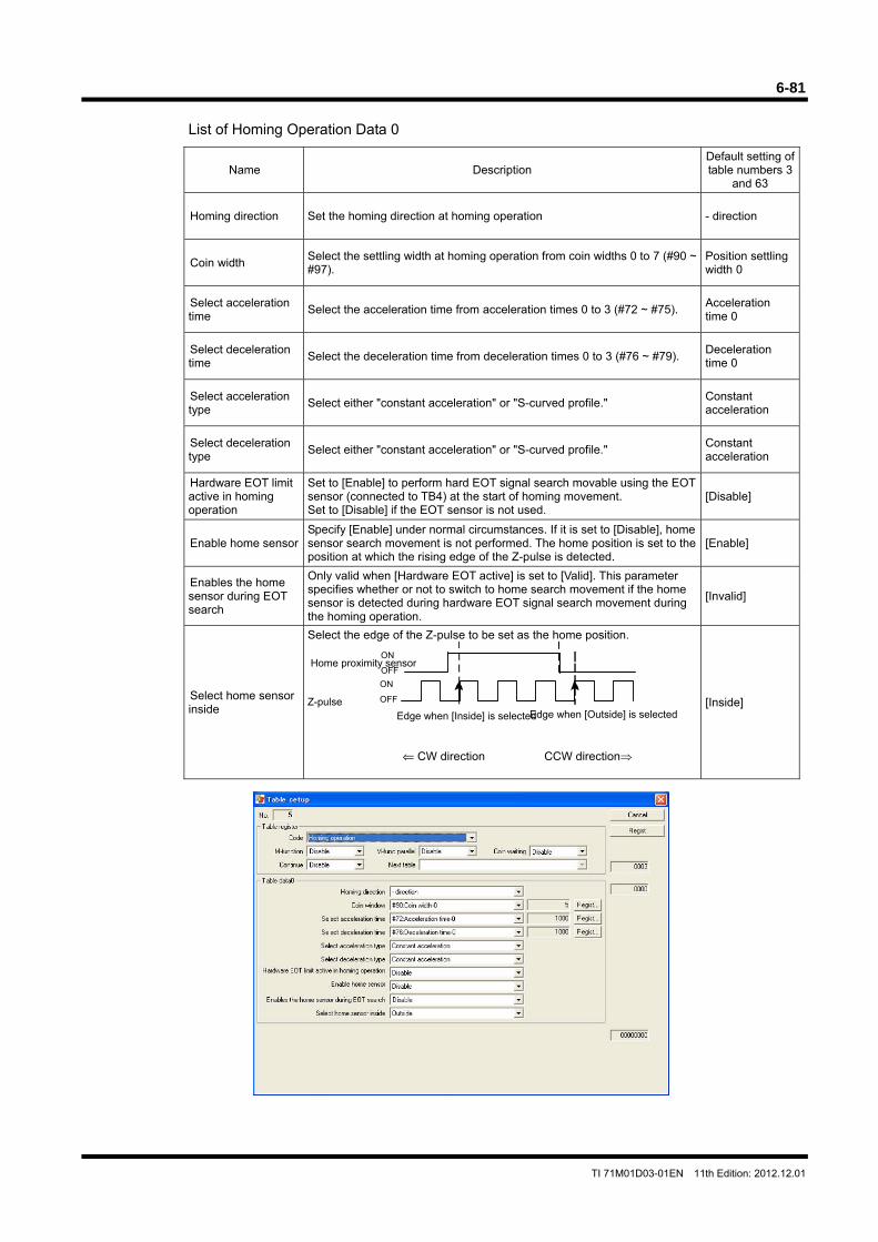
6-81
TI 71M01D03-01EN 11th Edition: 2012.12.01
List of Homing Operation Data 0
Name Description Default setting of table numbers 3
and 63
Homing direction Set the homing direction at homing operation - direction
Coin width Select the settling width at homing operation from coin widths 0 to 7 (#90 ~ #97).
Position settling width 0
Select acceleration time
Select the acceleration time from acceleration times 0 to 3 (#72 ~ #75). Acceleration time 0
Select deceleration time
Select the deceleration time from deceleration times 0 to 3 (#76 ~ #79). Deceleration time 0
Select acceleration type
Select either "constant acceleration" or "S-curved profile." Constant acceleration
Select deceleration type
Select either "constant acceleration" or "S-curved profile." Constant acceleration
Hardware EOT limit active in homing operation
Set to [Enable] to perform hard EOT signal search movable using the EOT sensor (connected to TB4) at the start of homing movement. Set to [Disable] if the EOT sensor is not used.
[Disable]
Enable home sensor Specify [Enable] under normal circumstances. If it is set to [Disable], home sensor search movement is not performed. The home position is set to the position at which the rising edge of the Z-pulse is detected.
[Enable]
Enables the home sensor during EOT search
Only valid when [Hardware EOT active] is set to [Valid]. This parameter specifies whether or not to switch to home search movement if the home sensor is detected during hardware EOT signal search movement during the homing operation.
[Invalid]
Select home sensor inside
Select the edge of the Z-pulse to be set as the home position. Z-pulse
⇐ CW direction CCW direction
[Inside]
Home proximity sensor
Edge when [Inside] is selectedEdge when [Outside] is selected
ON
OFF
ON
OFF
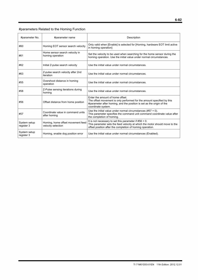
6-82
TI 71M01D03-01EN 11th Edition: 2012.12.01
#parameters Related to the Homing Function
#parameter No. #parameter name Description
#60 Homing EOT sensor search velocityOnly valid when [Enable] is selected for [Homing, hardware EOT limit active in homing operation]
#61 Home sensor search velocity in homing operation
Set the velocity to be used when searching for the home sensor during the homing operation. Use the initial value under normal circumstances.
#62 Initial Z-pulse search velocity Use the initial value under normal circumstances.
#63 Z-pulse search velocity after 2nd iteration
Use the initial value under normal circumstances.
#55 Overshoot distance in homing operation
Use the initial value under normal circumstances.
#58 Z-Pulse sensing iterations during homing
Use the initial value under normal circumstances.
#56 Offset distance from home position
Enter the amount of home offset. The offset movement is only performed for the amount specified by this #parameter after homing, and the position is set as the origin of the coordinate system.
#57 Coordinate value in command units after homing
Use the initial value under normal circumstances (#57 = 0). This parameter specifies the command unit command coordinate value after the completion of homing.
System setup register 3
Homing, home offset movement feed velocity selection
It is not necessary to set this parameter if #56 = 0. This parameter sets the feed velocity at which the motor should move to the offset position after the completion of homing operation.
System setup register 3
Homing, enable dog position error Use the initial value under normal circumstances (Enabled).
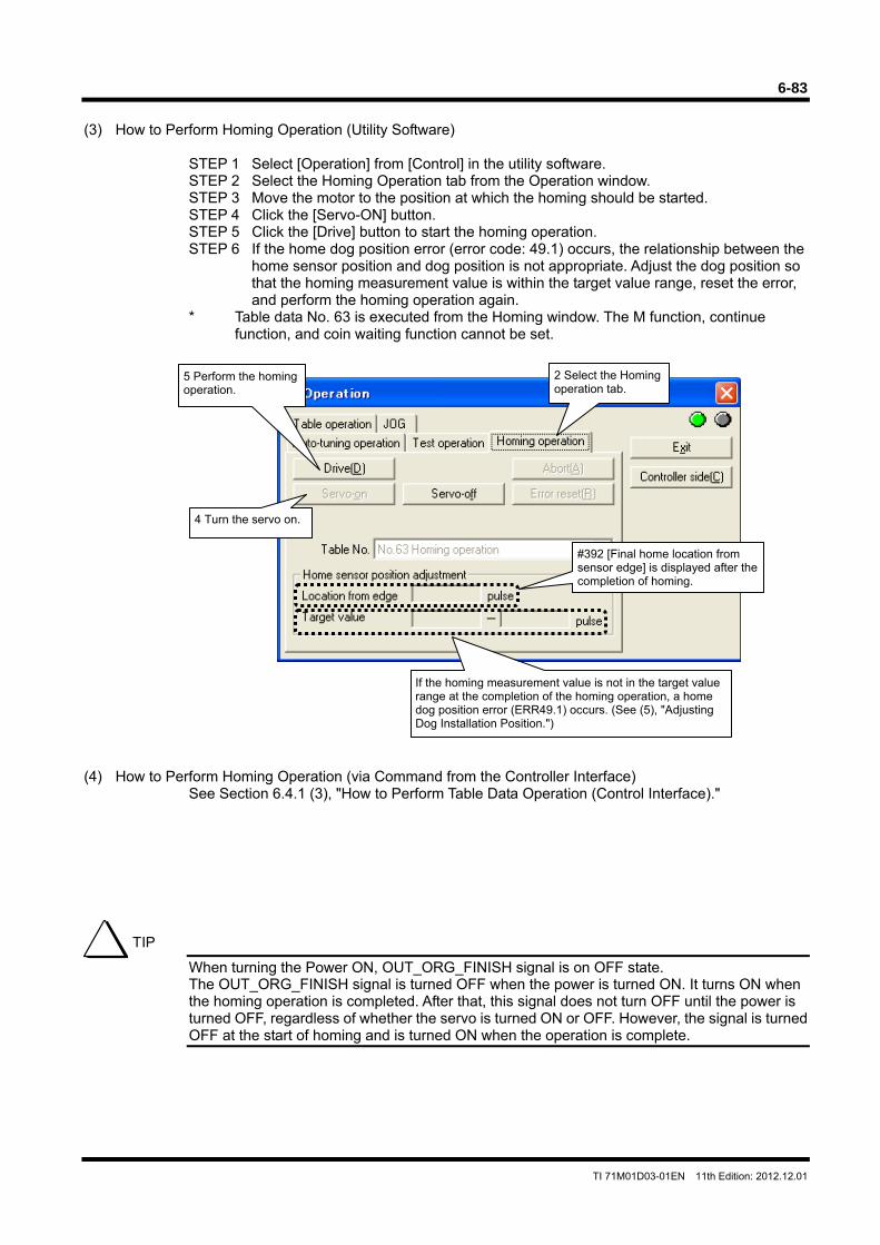
6-83
TI 71M01D03-01EN 11th Edition: 2012.12.01
(3) How to Perform Homing Operation (Utility Software)
STEP 1 Select [Operation] from [Control] in the utility software. STEP 2 Select the Homing Operation tab from the Operation window. STEP 3 Move the motor to the position at which the homing should be started. STEP 4 Click the [Servo-ON] button. STEP 5 Click the [Drive] button to start the homing operation. STEP 6 If the home dog position error (error code: 49.1) occurs, the relationship between the
home sensor position and dog position is not appropriate. Adjust the dog position so that the homing measurement value is within the target value range, reset the error, and perform the homing operation again.
* Table data No. 63 is executed from the Homing window. The M function, continue function, and coin waiting function cannot be set.
(4) How to Perform Homing Operation (via Command from the Controller Interface)
See Section 6.4.1 (3), "How to Perform Table Data Operation (Control Interface)."
When turning the Power ON, OUT_ORG_FINISH signal is on OFF state. The OUT_ORG_FINISH signal is turned OFF when the power is turned ON. It turns ON when the homing operation is completed. After that, this signal does not turn OFF until the power is turned OFF, regardless of whether the servo is turned ON or OFF. However, the signal is turned OFF at the start of homing and is turned ON when the operation is complete.
TIP
5 Perform the homing operation.
2 Select the Homing operation tab.
4 Turn the servo on.
#392 [Final home location from sensor edge] is displayed after the completion of homing.
If the homing measurement value is not in the target value range at the completion of the homing operation, a home dog position error (ERR49.1) occurs. (See (5), "Adjusting Dog Installation Position.")
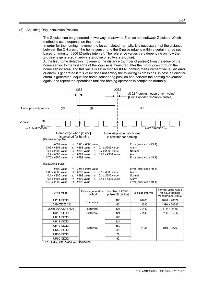
6-84
TI 71M01D03-01EN 11th Edition: 2012.12.01
(5) Adjusting Dog Installation Position
The Z-pulse can be generated in two ways (hardware Z-pulse and software Z-pulse). Which method is used depends on the motor. In order for the homing movement to be completed normally, it is necessary that the distance between the ON area of the home sensor and the Z-pulse edge is within a certain range set based on monitor #306 [Z-pulse interval]. The reference values vary depending on how the Z-pulse is generated (hardware Z-pulse or software Z-pulse). At the first home detection movement, the distance (number of pulses) from the edge of the home sensor to the first edge of the Z-pulse is measured after the motor goes through the home sensor area, and this value is set in monitor #392 [homing measurement value]. An error or alarm is generated if this value does not satisfy the following expressions. In case an error or alarm is generated, adjust the home sensor dog position and perform the homing movement again, and repeat the operations until the homing operation is completed normally.
⇐ CW direction CCW direction
[Hardware Z-pulse]
#392 value < 0.05 x #306 value Error (error code 49.1) 0.05 x #306 value ≤ #392 value < 0.1 x #306 value Alarm 0.1 x #306 value ≤ #392 value ≤ 0.7 x #306 value Normal 0.7 x #306 value < #392 value ≤ 0.75 x #306 value Alarm 0.75 x #306 value < #392 value Error (error code 49.1) [Software Z-pulse]
#392 value < 0.05 x #306 value Error (error code 49.1) 0.05 x #306 value ≤ #392 value < 0.1 x #306 value Alarm 0.1 x #306 value ≤ #392 value ≤ 0.4 x #306 value Normal 0.4 x #306 value < #392 value ≤ 0.45 x #306 value Alarm 0.45 x #306 value < #392 value Error (error code 49.1)
Drive model Z-pulse generation
method Number of ZERO pulses [1/rotation]
Z-pulse interval Normal value range
for #392 [homing measurement value]
UD1A- Hardware
100 40960 4096 ~ 28672
UD1B- (*1) 60 43690 4396 ~ 30583
UD1B-004/UD1B-006 Software 124 21140 2114 ~ 8456
UD1C- Software 124 21140 2114 ~ 8456
UR1A-
Software
200
8192 819 ~ 3276
UR1B- 124
UR1E- 150
UR5B- 68
UR5E- 78
UR5C- 52 *1 Excluding UD1B-004 and UD1B-006
ON
OFF
ON OFFOFF
#392#392
Home proximity sensor
Z-pulse
Home edge when [Inside] is selected for homing
#392 [homing measurement value][Unit: Encoder resolution pulses]
Home edge when [Outside] is selected for homing
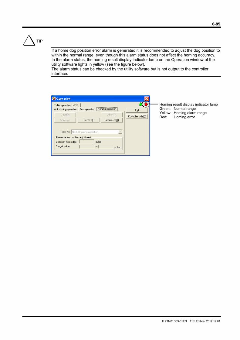
6-85
TI 71M01D03-01EN 11th Edition: 2012.12.01
If a home dog position error alarm is generated it is recommended to adjust the dog position to within the normal range, even though this alarm status does not affect the homing accuracy. In the alarm status, the homing result display indicator lamp on the Operation window of the utility software lights in yellow (see the figure below). The alarm status can be checked by the utility software but is not output to the controller interface.
TIP
Homing result display indicator lamp Green: Normal range Yellow: Homing alarm range Red: Homing error
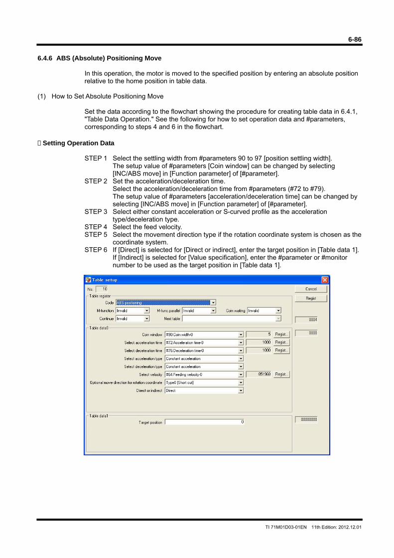
6-86
TI 71M01D03-01EN 11th Edition: 2012.12.01
6.4.6 ABS (Absolute) Positioning Move
In this operation, the motor is moved to the specified position by entering an absolute position relative to the home position in table data.
(1) How to Set Absolute Positioning Move
Set the data according to the flowchart showing the procedure for creating table data in 6.4.1, "Table Data Operation." See the following for how to set operation data and #parameters, corresponding to steps 4 and 6 in the flowchart.
Setting Operation Data
STEP 1 Select the settling width from #parameters 90 to 97 [position settling width].
The setup value of #parameters [Coin window] can be changed by selecting [INC/ABS move] in [Function parameter] of [#parameter].
STEP 2 Set the acceleration/deceleration time. Select the acceleration/deceleration time from #parameters (#72 to #79). The setup value of #parameters [acceleration/deceleration time] can be changed by selecting [INC/ABS move] in [Function parameter] of [#parameter].
STEP 3 Select either constant acceleration or S-curved profile as the acceleration type/deceleration type.
STEP 4 Select the feed velocity. STEP 5 Select the movement direction type if the rotation coordinate system is chosen as the
coordinate system. STEP 6 If [Direct] is selected for [Direct or indirect], enter the target position in [Table data 1].
If [Indirect] is selected for [Value specification], enter the #parameter or #monitor number to be used as the target position in [Table data 1].
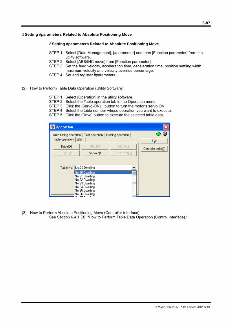
6-87
TI 71M01D03-01EN 11th Edition: 2012.12.01
Setting #parameters Related to Absolute Positioning Move
Setting #parameters Related to Absolute Positioning Move
STEP 1 Select [Data Management], [#parameter] and then [Function parameter] from the
utility software. STEP 2 Select [ABS/INC move] from [Function parameter]. STEP 3 Set the feed velocity, acceleration time, deceleration time, position settling width,
maximum velocity and velocity override percentage. STEP 4 Set and register #parameters.
(2) How to Perform Table Data Operation (Utility Software)
STEP 1 Select [Operation] in the utility software. STEP 2 Select the Table operation tab in the Operation menu. STEP 3 Click the [Servo-ON] button to turn the motor's servo ON. STEP 4 Select the table number whose operation you want to execute. STEP 5 Click the [Drive] button to execute the selected table data.
(3) How to Perform Absolute Positioning Move (Controller Interface)
See Section 6.4.1 (3), "How to Perform Table Data Operation (Control Interface)."
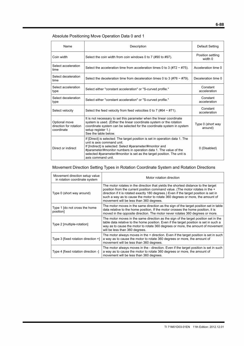
6-88
TI 71M01D03-01EN 11th Edition: 2012.12.01
Absolute Positioning Move Operation Data 0 and 1
Name Description Default Setting
Coin width Select the coin width from coin windows 0 to 7 (#90 to #97). Position settling
width 0
Select acceleration time
Select the acceleration time from acceleration times 0 to 3 (#72 ~ #75). Acceleration time 0
Select deceleration time
Select the deceleration time from deceleration times 0 to 3 (#76 ~ #79). Deceleration time 0
Select acceleration type
Select either "constant acceleration" or "S-curved profile." Constant
acceleration
Select deceleration type
Select either "constant acceleration" or "S-curved profile." Constant
acceleration
Select velocity Select the feed velocity from feed velocities 0 to 7 (#64 ~ #71). Constant
acceleration
Optional move direction for rotation coordinate
It is not necessary to set this parameter when the linear coordinate system is used. (Either the linear coordinate system or the rotation coordinate system can be selected for the coordinate system in system setup register 1.) See the table below.
Type 0 (short way around)
Direct or indirect
If [Direct] is selected: The target position is set in operation data 1. The unit is axis command unit. If [Indirect] is selected: Select #parameter/#monitor and #parameter/#monitor numbers in operation data 1. The value of the selected #parameter/#monitor is set as the target position. The unit is axis command unit.
0 (Disabled)
Movement Direction Setting Types in Rotation Coordinate System and Rotation Directions
Movement direction setup value in rotation coordinate system
Motor rotation direction
Type 0 (short way around)
The motor rotates in the direction that yields the shortest distance to the target position from the current position command value. (The motor rotates in the + direction if it is rotated exactly 180 degrees.) Even if the target position is set in such a way as to cause the motor to rotate 360 degrees or more, the amount of movement will be less than 360 degrees.
Type 1 [do not cross the home position]
The motor moves in the same direction as the sign of the target position set in table data relative to the home position. If the motor crosses the home position, it is moved in the opposite direction. The motor never rotates 360 degrees or more.
Type 2 [multiple-rotation]
The motor moves in the same direction as the sign of the target position set in the table data relative to the home position. Even if the target position is set in such a way as to cause the motor to rotate 360 degrees or more, the amount of movement will be less than 360 degrees.
Type 3 [fixed rotation direction +] The motor always moves in the + direction. Even if the target position is set in such a way as to cause the motor to rotate 360 degrees or more, the amount of movement will be less than 360 degrees.
Type 4 [fixed rotation direction -] The motor always moves in the - direction. Even if the target position is set in such a way as to cause the motor to rotate 360 degrees or more, the amount of movement will be less than 360 degrees.
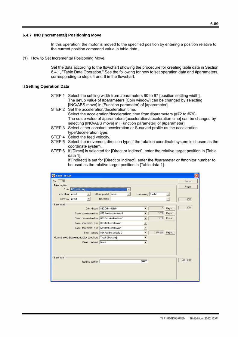
6-89
TI 71M01D03-01EN 11th Edition: 2012.12.01
6.4.7 INC (Incremental) Positioning Move
In this operation, the motor is moved to the specified position by entering a position relative to the current position command value in table data.
(1) How to Set Incremental Positioning Move
Set the data according to the flowchart showing the procedure for creating table data in Section 6.4.1, "Table Data Operation." See the following for how to set operation data and #parameters, corresponding to steps 4 and 6 in the flowchart.
Setting Operation Data
STEP 1 Select the settling width from #parameters 90 to 97 [position settling width].
The setup value of #parameters [Coin window] can be changed by selecting [INC/ABS move] in [Function parameter] of [#parameter].
STEP 2 Set the acceleration/deceleration time. Select the acceleration/deceleration time from #parameters (#72 to #79). The setup value of #parameters [acceleration/deceleration time] can be changed by selecting [INC/ABS move] in [Function parameter] of [#parameter].
STEP 3 Select either constant acceleration or S-curved profile as the acceleration type/deceleration type.
STEP 4 Select the feed velocity. STEP 5 Select the movement direction type if the rotation coordinate system is chosen as the
coordinate system. STEP 6 If [Direct] is selected for [Direct or indirect], enter the relative target position in [Table
data 1]. If [Indirect] is set for [Direct or indirect], enter the #parameter or #monitor number to be used as the relative target position in [Table data 1].
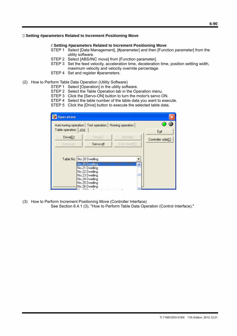
6-90
TI 71M01D03-01EN 11th Edition: 2012.12.01
Setting #parameters Related to Increment Positioning Move
Setting #parameters Related to Increment Positioning Move STEP 1 Select [Data Management], [#parameter] and then [Function parameter] from the
utility software. STEP 2 Select [ABS/INC move] from [Function parameter]. STEP 3 Set the feed velocity, acceleration time, deceleration time, position settling width,
maximum velocity and velocity override percentage. STEP 4 Set and register #parameters.
(2) How to Perform Table Data Operation (Utility Software) STEP 1 Select [Operation] in the utility software. STEP 2 Select the Table Operation tab in the Operation menu. STEP 3 Click the [Servo-ON] button to turn the motor's servo ON. STEP 4 Select the table number of the table data you want to execute. STEP 5 Click the [Drive] button to execute the selected table data.
(3) How to Perform Increment Positioning Move (Controller Interface)
See Section 6.4.1 (3), "How to Perform Table Data Operation (Control Interface)."
6-91
TI 71M01D03-01EN 11th Edition: 2012.12.01
Increment Positioning Move Operation Data 0 and 1
Name Description Default Setting
Coin width Select the settling width at homing operation from coin widths 0 to 7 (#90 ~ #97).
Position settling width 0
Select acceleration time
Select the acceleration time from acceleration times 0 to 3 (#72 ~ #75). Acceleration time 0
Select deceleration time
Select the deceleration time from deceleration times 0 to 3 (#76 ~ #79). Deceleration time 0
Select acceleration type
Select either "constant acceleration" or "S-curved." Constant
acceleration
Select deceleration type
Select either "constant acceleration" or "S-curved." Constant
acceleration
Select velocity Select the feed velocity from feed velocities 0 to 7 (#64 ~ #71). Constant
acceleration
Optional move direction for rotation coordinate
It is not necessary to set this parameter when the linear coordinate system is used. (Either the linear coordinate system or the rotation coordinate system can be selected for the coordinate system in system setup register 1.) See the table below.
Type 0 (short way around)
Direct or indirect
If [Direct] is selected: The relative target position is set by operation data 1. The unit is axis command unit. If [Indirect] is selected: Select #parameter/#monitor and #parameter/#monitor numbers in operation data 1. The value of the selected #parameter/#monitor is set to the relative target position. The unit is axis command unit.
0 (Disabled)
Movement Direction Setting Types at Rotation Coordinates and Rotation Directions
Movement direction setup value in rotation coordinate system
Motor rotation direction
Type 0 (short way around)
Rotate in the direction that yields the shortest distance to the relative target position from the current position command value. (The motor rotates in the + direction if it is rotated exactly 180 degrees.) Even if the target position is set in such a way as to cause rotation of 360 degrees or more, the amount of movement will be less than 360 degrees.
Type 1 [do not cross the home position]
The motor moves in the same direction as the sign of the relative target position set in table data relative to the home position. If the motor crosses the home position, it is moved in the opposite direction. The motor never rotates 360 degrees or more.
Type 2 [multiple-rotation]
The motor moves in the same direction as the sign of the relative target position set in the table data relative to the home position. If the relative target position is set in such a way as to cause the motor to rotate 360 degrees or more, the motor may rotate several times.
Type 3 [fixed rotation direction +] The motor always moves in the + direction. Even if the target position is set in such a way as to cause rotation of 360 degrees or more, the amount of movement will be less than 360 degrees.
Type 4 [fixed rotation direction -] The motor always moves in the - direction. Even if the target position is set in such a way as to cause rotation of 360 degrees or more, the amount of movement will be less than 360 degrees.
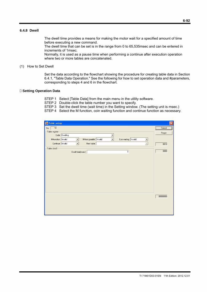
6-92
TI 71M01D03-01EN 11th Edition: 2012.12.01
6.4.8 Dwell
The dwell time provides a means for making the motor wait for a specified amount of time before executing a new command. The dwell time that can be set is in the range from 0 to 65,535msec and can be entered in increments of 1msec. Normally, it is used as a pause time when performing a continue after execution operation where two or more tables are concatenated.
(1) How to Set Dwell
Set the data according to the flowchart showing the procedure for creating table data in Section 6.4.1, "Table Data Operation." See the following for how to set operation data and #parameters, corresponding to steps 4 and 6 in the flowchart.
Setting Operation Data
STEP 1 Select [Table Data] from the main menu in the utility software. STEP 2 Double-click the table number you want to specify. STEP 3 Set the dwell time (wait time) in the Setting window. (The setting unit is msec.) STEP 4 Select the M function, coin waiting function and continue function as necessary.
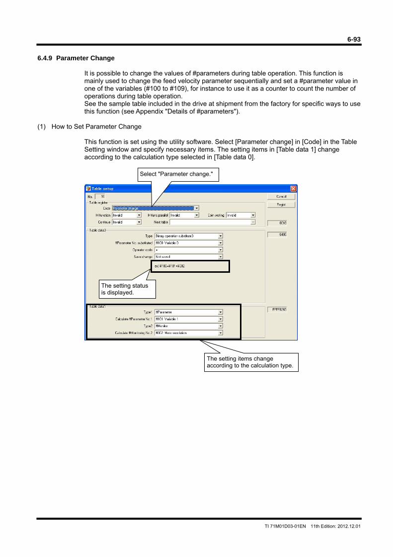
6-93
TI 71M01D03-01EN 11th Edition: 2012.12.01
6.4.9 Parameter Change
It is possible to change the values of #parameters during table operation. This function is mainly used to change the feed velocity parameter sequentially and set a #parameter value in one of the variables (#100 to #109), for instance to use it as a counter to count the number of operations during table operation. See the sample table included in the drive at shipment from the factory for specific ways to use this function (see Appendix "Details of #parameters").
(1) How to Set Parameter Change
This function is set using the utility software. Select [Parameter change] in [Code] in the Table Setting window and specify necessary items. The setting items in [Table data 1] change according to the calculation type selected in [Table data 0].
Select "Parameter change."
The setting status is displayed.
The setting items change according to the calculation type.
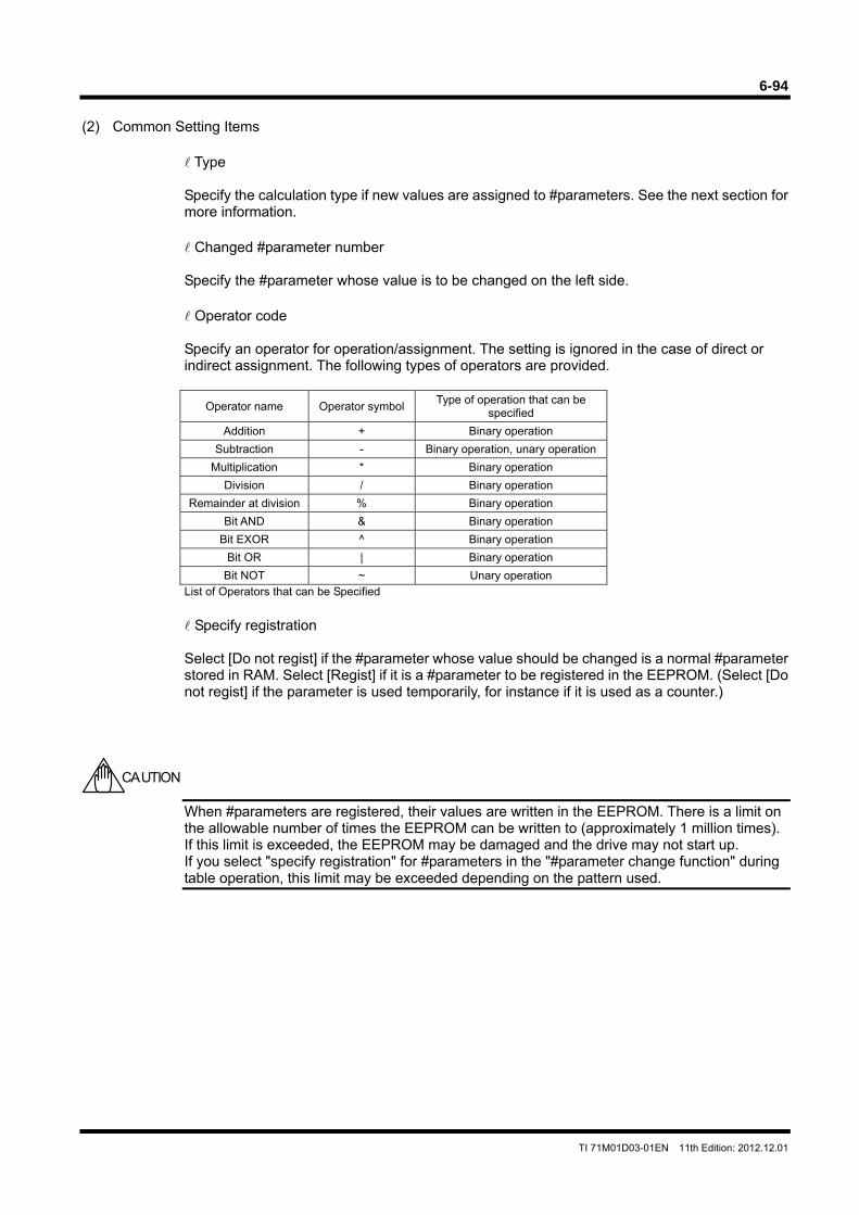
6-94
TI 71M01D03-01EN 11th Edition: 2012.12.01
(2) Common Setting Items
Type Specify the calculation type if new values are assigned to #parameters. See the next section for more information. Changed #parameter number Specify the #parameter whose value is to be changed on the left side. Operator code Specify an operator for operation/assignment. The setting is ignored in the case of direct or indirect assignment. The following types of operators are provided.
Operator name Operator symbolType of operation that can be
specified
Addition + Binary operation
Subtraction - Binary operation, unary operation
Multiplication * Binary operation
Division / Binary operation
Remainder at division % Binary operation
Bit AND & Binary operation
Bit EXOR ^ Binary operation
Bit OR | Binary operation
Bit NOT ~ Unary operation List of Operators that can be Specified
Specify registration Select [Do not regist] if the #parameter whose value should be changed is a normal #parameter stored in RAM. Select [Regist] if it is a #parameter to be registered in the EEPROM. (Select [Do not regist] if the parameter is used temporarily, for instance if it is used as a counter.)
When #parameters are registered, their values are written in the EEPROM. There is a limit on the allowable number of times the EEPROM can be written to (approximately 1 million times). If this limit is exceeded, the EEPROM may be damaged and the drive may not start up. If you select "specify registration" for #parameters in the "#parameter change function" during table operation, this limit may be exceeded depending on the pattern used.
CAUTION
6-95
TI 71M01D03-01EN 11th Edition: 2012.12.01
(3) Explanation of Each Operation Type
With the parameter change function, it is possible not only to change the values of the specified #parameters to simple values, but also to results of calculation operations.
Direct Assignment
The value (signed 32-bit value) specified by operation data 1 is assigned directly to the specified target #parameter. At this point, the setting of operator code is ignored.
Examples: #100 = 123 #100 = -123 ##100 = 123
Indirect Assignment
The value of the #parameter/#monitor number specified by table data 1 is assigned to the specified target #parameter. The specified #parameter number is a #parameter in RAM. At this point, the setting of operator code is ignored.
Example: #100 = #101
Unary Operation Assignment 1
The value (signed 32-bit value) specified by table data 1 is assigned directly to the specified target #parameter after carrying out an operation. Only "subtraction (-)" and "bit NOT (~)" can be specified as the operator. If an operator that cannot be used is specified, the specification is rejected and a "50.5 not executable error" is generated.
Example: #100 = ~123
Unary Operation Assignment 2
The value of the #parameter/#monitor number specified by table data 1 is assigned to the specified target #parameter after carrying out an operation. Only "subtraction (-)" and "bit NOT (~)" can be specified as the operator. If an operator that cannot be used is specified, the specification is rejected and a "50.5 not executable error" is generated.
Example: #100 = ~#101
Binary Operation Assignment 1
The result of an operation between the direct value (signed 24-bit value) and the value of the #parameter/#monitor number specified by table data 1 is assigned to the specified target #parameter. If an operator that cannot be used is specified, the specification is rejected and a "50.5 not executable error" is generated.
Example: #100 = 123 + #101
6-96
TI 71M01D03-01EN 11th Edition: 2012.12.01
Binary Operation Assignment 2
The result of an operation between the value of the #parameter/#monitor number and the direct value (signed 24-bit value) specified by table data 1 is assigned to the specified target #parameter. If an operator that cannot be used is specified, the specification is rejected and a "50.5 not executable error" is generated.
Example: #100 = #101 + 123
Binary operation substitution 3
The result of an operation between the values of the two #parameter/#monitor numbers specified by table data 1 is assigned to the specified target #parameter. If an operator that cannot be used is specified, the specification is rejected and a "50.5 not executable error" is generated.
Example: #100 = #101 + #102
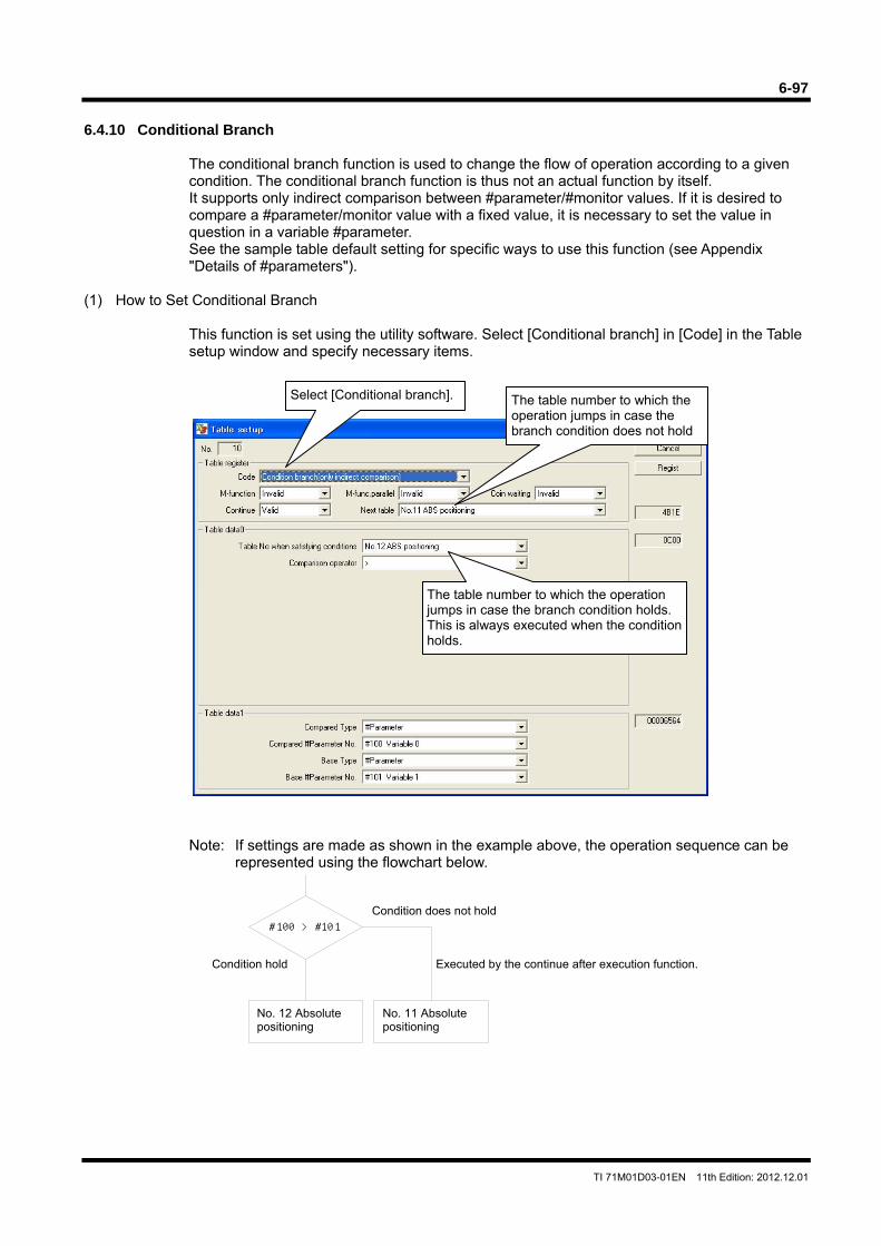
6-97
TI 71M01D03-01EN 11th Edition: 2012.12.01
6.4.10 Conditional Branch
The conditional branch function is used to change the flow of operation according to a given condition. The conditional branch function is thus not an actual function by itself. It supports only indirect comparison between #parameter/#monitor values. If it is desired to compare a #parameter/monitor value with a fixed value, it is necessary to set the value in question in a variable #parameter. See the sample table default setting for specific ways to use this function (see Appendix "Details of #parameters").
(1) How to Set Conditional Branch This function is set using the utility software. Select [Conditional branch] in [Code] in the Table setup window and specify necessary items.
Note: If settings are made as shown in the example above, the operation sequence can be represented using the flowchart below.
Select [Conditional branch]. The table number to which the operation jumps in case the branch condition does not hold
The table number to which the operation jumps in case the branch condition holds. This is always executed when the condition holds.
#100 > #101
No. 12 Absolute positioning
No. 11 Absolute positioning
Condition does not hold
Executed by the continue after execution function. Condition hold
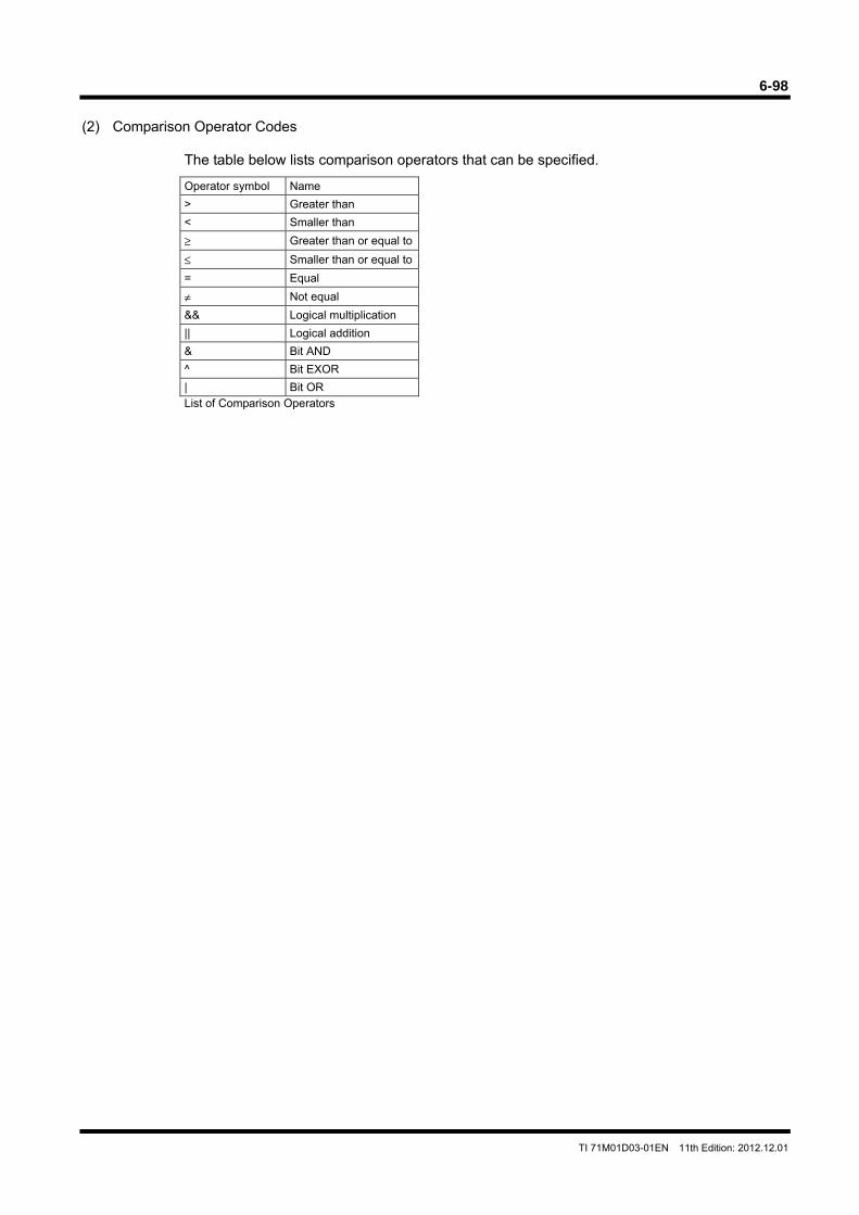
6-98
TI 71M01D03-01EN 11th Edition: 2012.12.01
(2) Comparison Operator Codes
The table below lists comparison operators that can be specified.
Operator symbol Name
> Greater than
< Smaller than
≥ Greater than or equal to
≤ Smaller than or equal to
= Equal
≠ Not equal
&& Logical multiplication
|| Logical addition
& Bit AND
^ Bit EXOR
| Bit OR List of Comparison Operators
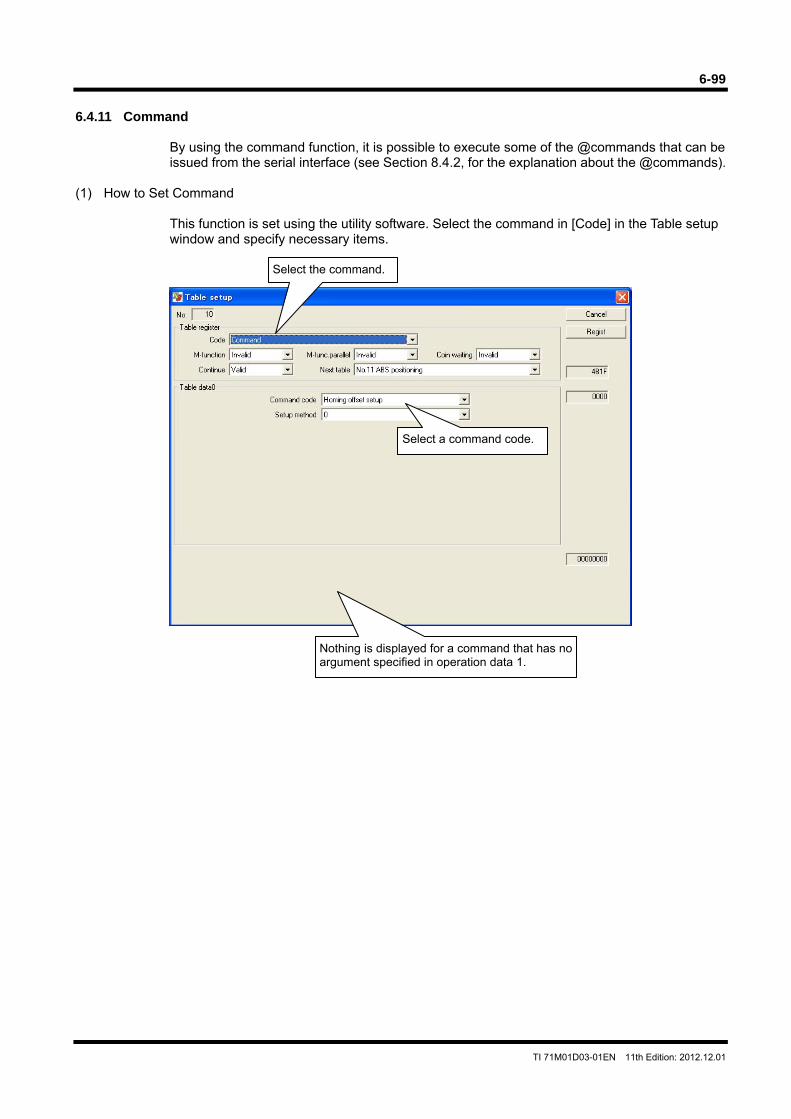
6-99
TI 71M01D03-01EN 11th Edition: 2012.12.01
6.4.11 Command
By using the command function, it is possible to execute some of the @commands that can be issued from the serial interface (see Section 8.4.2, for the explanation about the @commands).
(1) How to Set Command This function is set using the utility software. Select the command in [Code] in the Table setup window and specify necessary items.
Select the command.
Select a command code.
Nothing is displayed for a command that has no argument specified in operation data 1.
6-100
TI 71M01D03-01EN 11th Edition: 2012.12.01
(2) Details of Commands Home Offset Position Setting
The home offset position setup command is used to automatically calculate the value of parameter #56 [homing, amount of home offset movement] in such a way that the current motor position is set as the position after the completion of subsequent homing operations. Specify how to determine parameter #56 with the argument. Note that the calculation method differs depending on whether the coordinate system selected at execution is the linear coordinate system or the rotation coordinate system. This command has the same function as the @10 command of the serial interface.
When the Rotation Coordinate System is Used
When the rotation coordinate system is used, the home offset position is calculated as A = current command unit current value + #56.
The calculation method varies depending on the setting method specified by the argument.
If the setting method is 0 (offset to the closer position): 0 ≤ A ≤ (#112 [scaling command unit coordinate system] / 2 #56 = A Other than above #56 = A - #112
If the setting method is 1 (offset in the + direction): #56 = A
If the setting method is 2 (offset in the - direction): #56 = A - #112
When the Linear Coordinate System is Used When the linear coordinate system is used, the argument is ignored and the home offset position is always set as follow.
#56 = current command unit current value + value set in #56
Use this command after a homing operation is completed with parameter #57 [command unit command value after homing completion] set to 0. If the command is issued when the parameter is other than 0, the setting will not be made correctly. Make sure to execute this command after performing a homing operation.
CAUTION
6-101
TI 71M01D03-01EN 11th Edition: 2012.12.01
Coordinate System Setting
The coordinate system setup command is used to set the current command unit command value to the value specified by the argument. The value can either be specified by direct value specification or indirect value specification (to the current command unit command value is set to the value of another #parameter). If it is attempted to set a negative value when the rotation coordinate system is used, a "17.2 coordinate system abnormal B error" occurs. This command has the same function as the @13 command of the serial interface.
Integral Limiter Self-adjustment
The integral limiter self-adjustment command is used to recalculate and set the values of the velocity integral limiter and position integral limiter set on the side selected by the controller interface (1 or 2).
The following #parameters are re-set according to the logic I/O input status.
IN_VELFREQ_SEL OFF: #6 [velocity integral limiter value 1] ON: #7 [velocity integral limiter value 2]
IN_POSFREQ_SEL OFF: #12 [position integral limiter value 1] ON: #13 [position integral limiter value 2]
#parameters to be re-set must be #parameters in RAM. Save the values of the registered parameters in the EEPROM as necessary. This command has the same function as the @14 command of the serial interface.
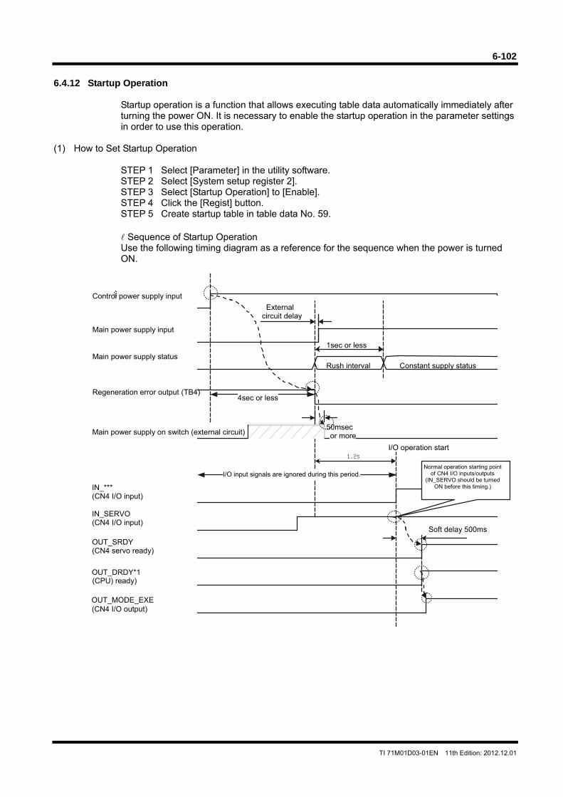
6-102
TI 71M01D03-01EN 11th Edition: 2012.12.01
1.2s
6.4.12 Startup Operation
Startup operation is a function that allows executing table data automatically immediately after turning the power ON. It is necessary to enable the startup operation in the parameter settings in order to use this operation.
(1) How to Set Startup Operation
STEP 1 Select [Parameter] in the utility software. STEP 2 Select [System setup register 2]. STEP 3 Select [Startup Operation] to [Enable]. STEP 4 Click the [Regist] button. STEP 5 Create startup table in table data No. 59.
Sequence of Startup Operation Use the following timing diagram as a reference for the sequence when the power is turned ON.
Soft delay 500ms
Main power supply input
Control power supply input
Main power supply status
Regeneration error output (TB4)
Main power supply on switch (external circuit)
Rush interval Constant supply status
External circuit delay
1sec or less
IN_*** (CN4 I/O input)
4sec or less
50msec or more
I/O input signals are ignored during this period.
(CPU) ready)
IN_SERVO (CN4 I/O input)
OUT_SRDY (CN4 servo ready)
(CN4 I/O output)
I/O operation start
Normal operation starting point of CN4 I/O inputs/outputs
(IN_SERVO should be turned ON before this timing.)
OUT_DRDY*1
OUT_MODE_EXE
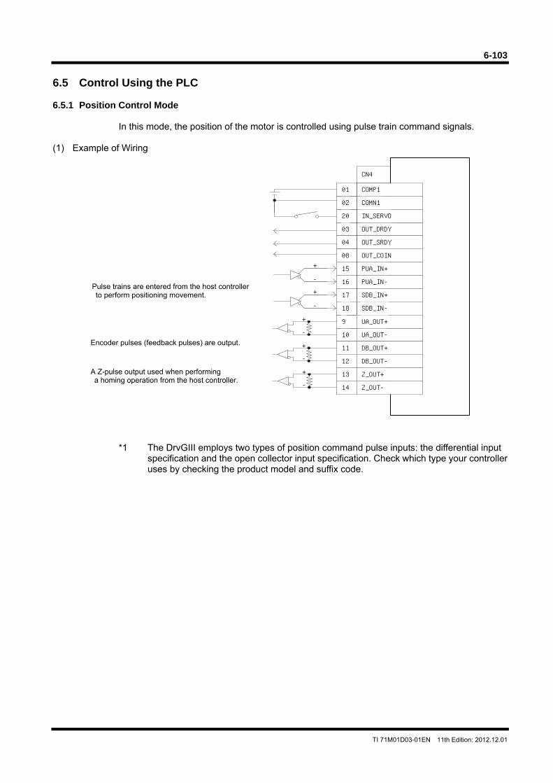
6-103
TI 71M01D03-01EN 11th Edition: 2012.12.01
6.5 Control Using the PLC 6.5.1 Position Control Mode
In this mode, the position of the motor is controlled using pulse train command signals. (1) Example of Wiring
*1 The DrvGIII employs two types of position command pulse inputs: the differential input specification and the open collector input specification. Check which type your controller uses by checking the product model and suffix code.
COMP1
COMN1
OUT_COIN
OUT_DRDY
OUT_SRDY
IN_SERVO
01
02
20
08
03
04
CN4
PUA_IN-
PUA_IN+
16
15
SDB_IN+17
SDB_IN-18
10
9
12
11
14
13
UA_OUT-
UA_OUT+
DB_OUT-
DB_OUT+
Z_OUT-
Z_OUT+
+
-
+
-
+
-
+
-
+
-
A Z-pulse output used when performing a homing operation from the host controller.
Encoder pulses (feedback pulses) are output.
Pulse trains are entered from the host controller to perform positioning movement.
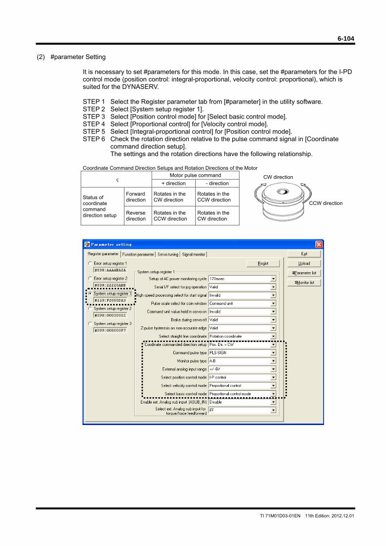
6-104
TI 71M01D03-01EN 11th Edition: 2012.12.01
CW direction
CCW direction
(2) #parameter Setting
It is necessary to set #parameters for this mode. In this case, set the #parameters for the I-PD control mode (position control: integral-proportional, velocity control: proportional), which is suited for the DYNASERV. STEP 1 Select the Register parameter tab from [#parameter] in the utility software. STEP 2 Select [System setup register 1]. STEP 3 Select [Position control mode] for [Select basic control mode]. STEP 4 Select [Proportional control] for [Velocity control mode]. STEP 5 Select [Integral-proportional control] for [Position control mode]. STEP 6 Check the rotation direction relative to the pulse command signal in [Coordinate
command direction setup]. The settings and the rotation directions have the following relationship.
Coordinate Command Direction Setups and Rotation Directions of the Motor
Motor pulse command
+ direction - direction
Status of coordinate command direction setup
Forward direction
Rotates in the CW direction
Rotates in the CCW direction
Reverse direction
Rotates in the CCW direction
Rotates in the CW direction
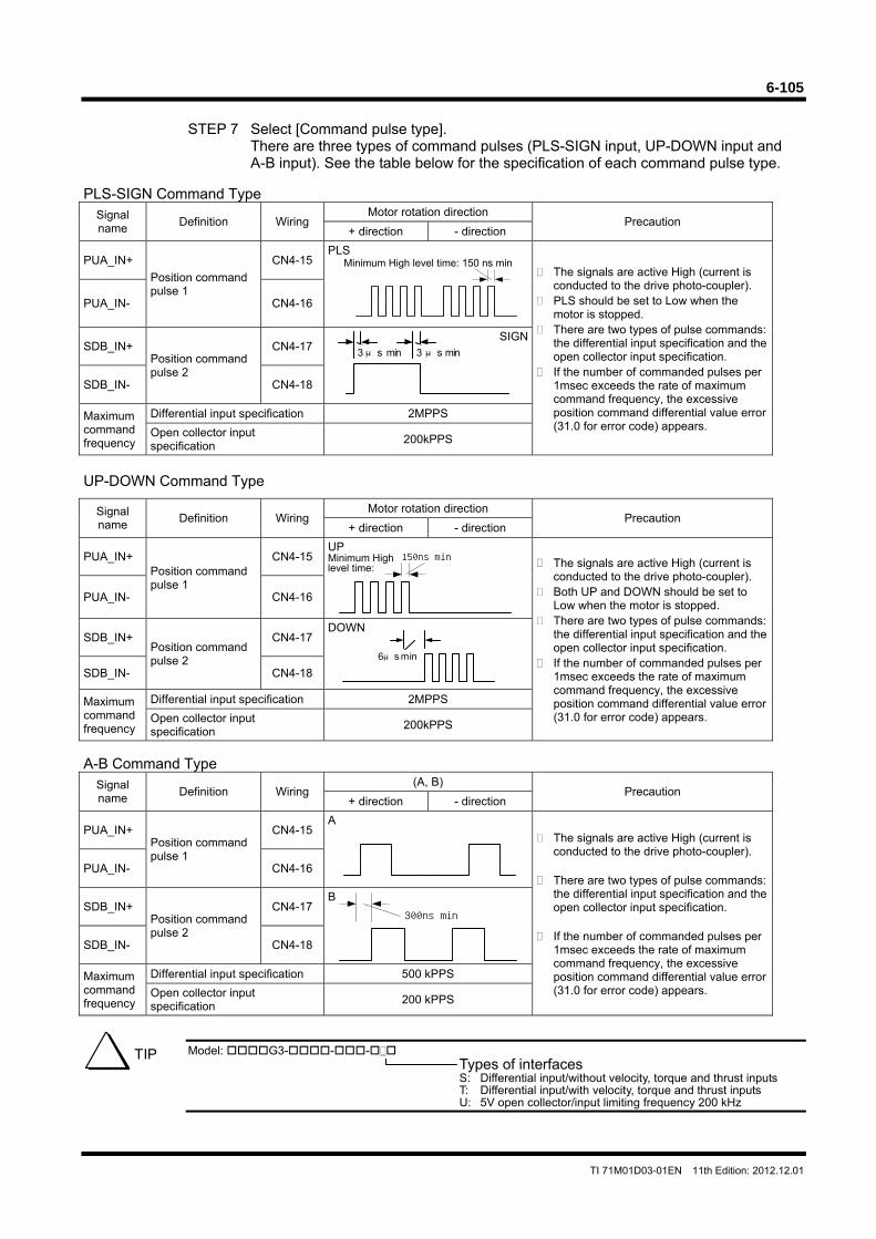
6-105
TI 71M01D03-01EN 11th Edition: 2012.12.01
150ns min
STEP 7 Select [Command pulse type].
There are three types of command pulses (PLS-SIGN input, UP-DOWN input and A-B input). See the table below for the specification of each command pulse type.
PLS-SIGN Command Type
Signal name
Definition Wiring Motor rotation direction
Precaution + direction - direction
PUA_IN+
Position command pulse 1
CN4-15 PLS
Minimum High level time: 150 ns min The signals are active High (current is
conducted to the drive photo-coupler). PLS should be set to Low when the
motor is stopped. There are two types of pulse commands:
the differential input specification and the open collector input specification.
If the number of commanded pulses per 1msec exceeds the rate of maximum command frequency, the excessive position command differential value error (31.0 for error code) appears.
PUA_IN- CN4-16
SDB_IN+ Position command pulse 2
CN4-17 SIGN
SDB_IN- CN4-18
Maximum command frequency
Differential input specification 2MPPS
Open collector input specification
200kPPS
UP-DOWN Command Type
Signal name
Definition Wiring Motor rotation direction
Precaution + direction - direction
PUA_IN+ Position command pulse 1
CN4-15 UP Minimum High level time: The signals are active High (current is
conducted to the drive photo-coupler). Both UP and DOWN should be set to
Low when the motor is stopped. There are two types of pulse commands:
the differential input specification and the open collector input specification.
If the number of commanded pulses per 1msec exceeds the rate of maximum command frequency, the excessive position command differential value error (31.0 for error code) appears.
PUA_IN- CN4-16
SDB_IN+ Position command pulse 2
CN4-17 DOWN
SDB_IN- CN4-18
Maximum command frequency
Differential input specification 2MPPS
Open collector input specification
200kPPS
A-B Command Type
Signal name
Definition Wiring (A, B)
Precaution + direction - direction
PUA_IN+ Position command pulse 1
CN4-15 A
The signals are active High (current is conducted to the drive photo-coupler).
There are two types of pulse commands:
the differential input specification and the open collector input specification.
If the number of commanded pulses per
1msec exceeds the rate of maximum command frequency, the excessive position command differential value error (31.0 for error code) appears.
PUA_IN- CN4-16
SDB_IN+ Position command pulse 2
CN4-17 B
SDB_IN- CN4-18
Maximum command frequency
Differential input specification 500 kPPS
Open collector input specification
200 kPPS
Model: G3---
Types of interfaces S: Differential input/without velocity, torque and thrust inputs T: Differential input/with velocity, torque and thrust inputs U: 5V open collector/input limiting frequency 200 kHz
TIP
3 μs min 3 μs min
6μs min
300ns min
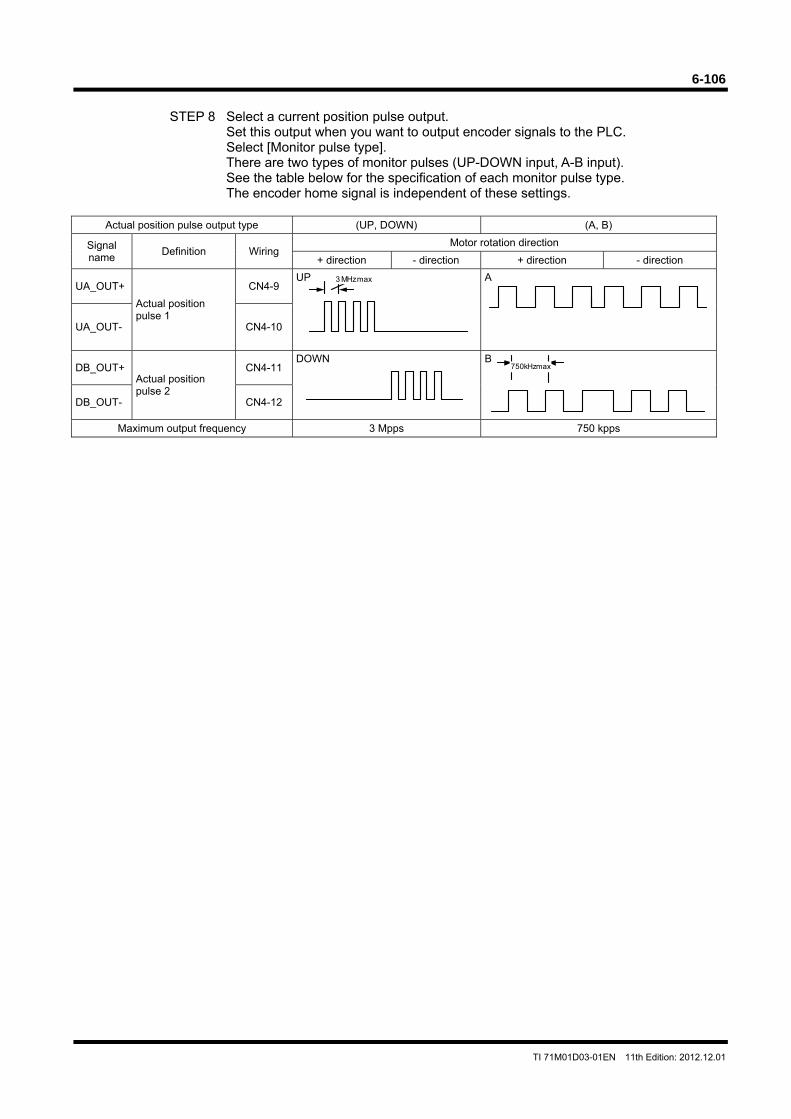
6-106
TI 71M01D03-01EN 11th Edition: 2012.12.01
STEP 8 Select a current position pulse output.
Set this output when you want to output encoder signals to the PLC. Select [Monitor pulse type]. There are two types of monitor pulses (UP-DOWN input, A-B input). See the table below for the specification of each monitor pulse type. The encoder home signal is independent of these settings.
Actual position pulse output type (UP, DOWN) (A, B)
Signal name
Definition Wiring Motor rotation direction
+ direction - direction + direction - direction
UA_OUT+
Actual position pulse 1
CN4-9 UP A
UA_OUT- CN4-10
DB_OUT+ Actual position pulse 2
CN4-11 DOWN B
DB_OUT- CN4-12
Maximum output frequency 3 Mpps 750 kpps
3 MHz max
750 kHz max

6-107
TI 71M01D03-01EN 11th Edition: 2012.12.01
(3) Servo Tuning
Perform auto-tuning (see Section 6.4.3). Note: If you cannot adjust the servo properly with auto-tuning, see Chapter 7, "Adjustment."
(4) Operation
To operate the motor using pulse train commands, the following conditions must be satisfied. OUT_BUSY: OFF OUT_DRDY: ON OUT_SRDY: ON
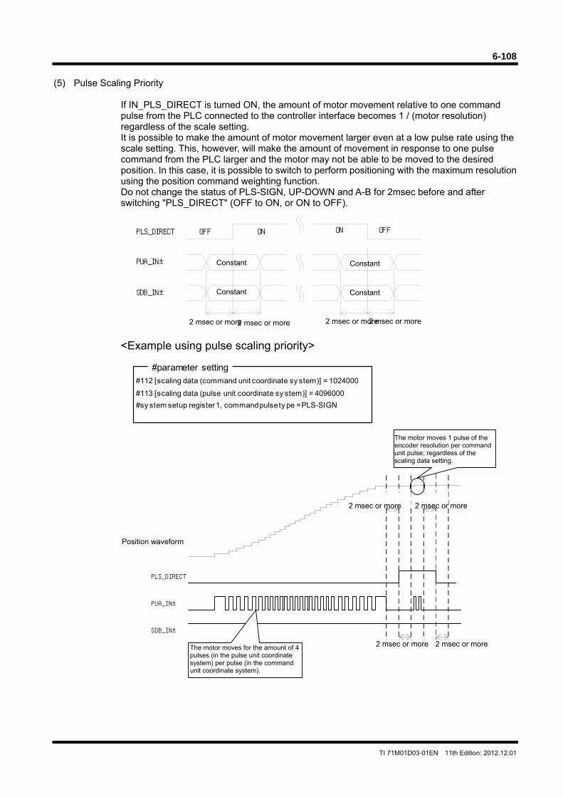
6-108
TI 71M01D03-01EN 11th Edition: 2012.12.01
(5) Pulse Scaling Priority
If IN_PLS_DIRECT is turned ON, the amount of motor movement relative to one command pulse from the PLC connected to the controller interface becomes 1 / (motor resolution) regardless of the scale setting. It is possible to make the amount of motor movement larger even at a low pulse rate using the scale setting. This, however, will make the amount of movement in response to one pulse command from the PLC larger and the motor may not be able to be moved to the desired position. In this case, it is possible to switch to perform positioning with the maximum resolution using the position command weighting function. Do not change the status of PLS-SIGN, UP-DOWN and A-B for 2msec before and after switching "PLS_DIRECT" (OFF to ON, or ON to OFF).
<Example using pulse scaling priority>
#112 [scaling data (command unit coordinate sy stem)] = 1024000
#113 [scaling data (pulse unit coordinate sy stem)] = 4096000
#sy stem setup register 1, command pulse ty pe = PLS-SIGN
#parameter setting
PLS_DIRECT
PUA_IN±
ONOFF
SDB_IN±
ON OFF
Constant
Constant
Constant
Constant
2 msec or more 2 msec or more2 msec or more2 msec or more
PUA_IN±
SDB_IN±
PLS_DIRECT
2 msec or more
Position waveform
The motor moves for the amount of 4 pulses (in the pulse unit coordinate system) per pulse (in the command unit coordinate system).
The motor moves 1 pulse of the encoder resolution per command unit pulse, regardless of the scaling data setting.
2 msec or more
2 msec or more 2 msec or more
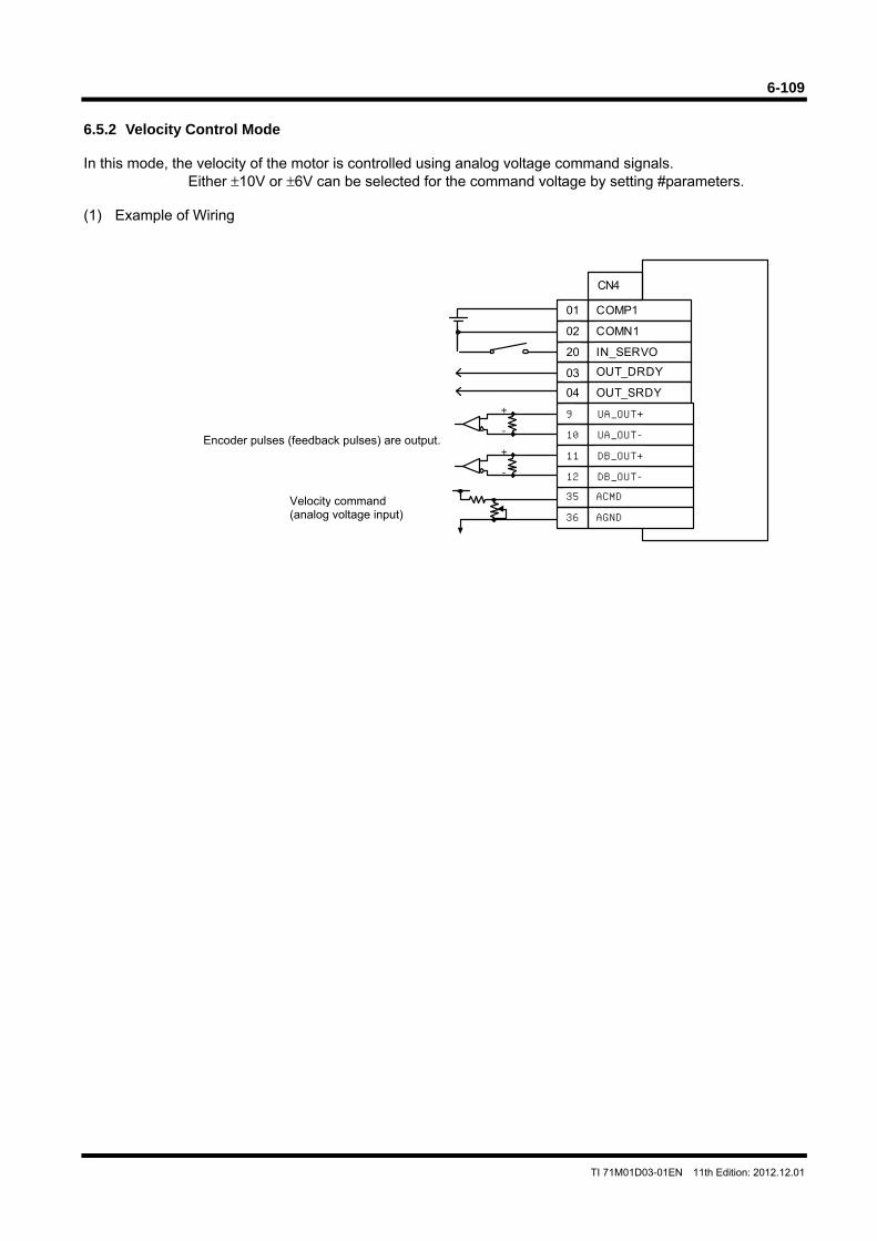
6-109
TI 71M01D03-01EN 11th Edition: 2012.12.01
COMP1
COMN1
OUT_DRDY
OUT_SRDY
IN_SERVO
01
02
20
03
04
CN4
ACMD35
AGND36
10
9
12
11
UA_OUT-
UA_OUT+
DB_OUT-
DB_OUT++
-
+
-
6.5.2 Velocity Control Mode In this mode, the velocity of the motor is controlled using analog voltage command signals.
Either ±10V or ±6V can be selected for the command voltage by setting #parameters. (1) Example of Wiring
Velocity command (analog voltage input)
Encoder pulses (feedback pulses) are output.
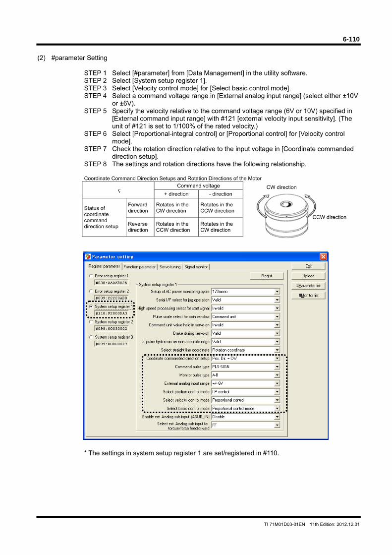
6-110
TI 71M01D03-01EN 11th Edition: 2012.12.01
CW direction
CCW direction
(2) #parameter Setting
STEP 1 Select [#parameter] from [Data Management] in the utility software. STEP 2 Select [System setup register 1]. STEP 3 Select [Velocity control mode] for [Select basic control mode]. STEP 4 Select a command voltage range in [External analog input range] (select either ±10V
or ±6V). STEP 5 Specify the velocity relative to the command voltage range (6V or 10V) specified in
[External command input range] with #121 [external velocity input sensitivity]. (The unit of #121 is set to 1/100% of the rated velocity.)
STEP 6 Select [Proportional-integral control] or [Proportional control] for [Velocity control mode].
STEP 7 Check the rotation direction relative to the input voltage in [Coordinate commanded direction setup].
STEP 8 The settings and rotation directions have the following relationship.
Coordinate Command Direction Setups and Rotation Directions of the Motor
Command voltage
+ direction - direction
Status of coordinate command direction setup
Forward direction
Rotates in the CW direction
Rotates in the CCW direction
Reverse direction
Rotates in the CCW direction
Rotates in the CW direction
* The settings in system setup register 1 are set/registered in #110.
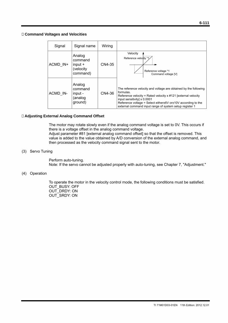
6-111
TI 71M01D03-01EN 11th Edition: 2012.12.01
Command Voltages and Velocities
Signal Signal name Wiring
ACMD_IN+
Analog command input + (velocity command)
CN4-35
Velocity The reference velocity and voltage are obtained by the following formulas. Reference velocity = Rated velocity x #121 [external velocity input sensitivity] x 0.0001 Reference voltage = Select either±6V or±10V according to the external command input range of system setup register 1
ACMD_IN-
Analog command input - (analog ground)
CN4-36
Adjusting External Analog Command Offset
The motor may rotate slowly even if the analog command voltage is set to 0V. This occurs if there is a voltage offset in the analog command voltage. Adjust parameter #81 [external analog command offset] so that the offset is removed. This value is added to the value obtained by A/D conversion of the external analog command, and then processed as the velocity command signal sent to the motor.
(3) Servo Tuning
Perform auto-tuning. Note: If the servo cannot be adjusted properly with auto-tuning, see Chapter 7, "Adjustment."
(4) Operation
To operate the motor in the velocity control mode, the following conditions must be satisfied. OUT_BUSY: OFF OUT_DRDY: ON OUT_SRDY: ON
Reference voltage *1 Command voltage [V]
Reference velocity *1
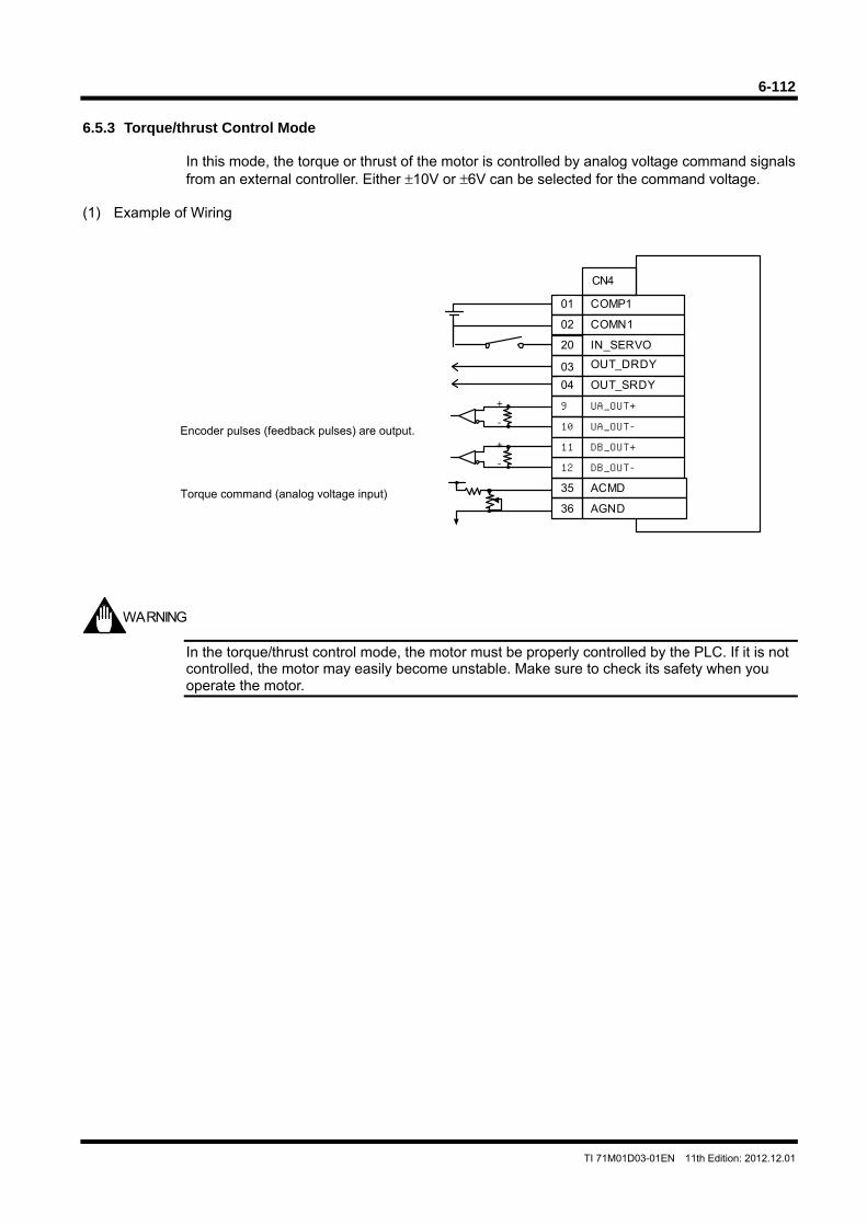
6-112
TI 71M01D03-01EN 11th Edition: 2012.12.01
6.5.3 Torque/thrust Control Mode
In this mode, the torque or thrust of the motor is controlled by analog voltage command signals from an external controller. Either ±10V or ±6V can be selected for the command voltage.
(1) Example of Wiring
In the torque/thrust control mode, the motor must be properly controlled by the PLC. If it is not controlled, the motor may easily become unstable. Make sure to check its safety when you operate the motor.
WARNING
COMP1
COMN1
OUT_DRDY
OUT_SRDY
IN_SERVO
01
02
20
03
04
CN4
10
9
12
11
UA_OUT-
UA_OUT+
DB_OUT-
DB_OUT++
-
+
-
ACMD35
AGND36Torque command (analog voltage input)
Encoder pulses (feedback pulses) are output.
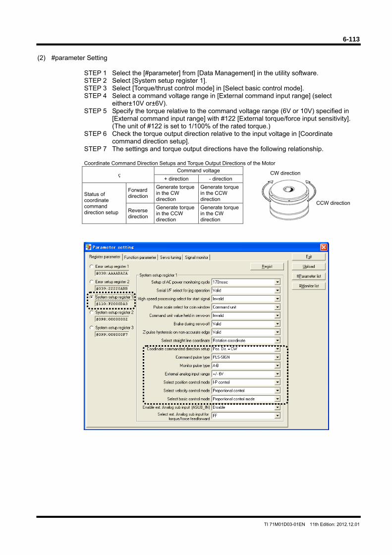
6-113
TI 71M01D03-01EN 11th Edition: 2012.12.01
CW direction
CCW direction
(2) #parameter Setting
STEP 1 Select the [#parameter] from [Data Management] in the utility software. STEP 2 Select [System setup register 1]. STEP 3 Select [Torque/thrust control mode] in [Select basic control mode]. STEP 4 Select a command voltage range in [External command input range] (select
either±10V or±6V). STEP 5 Specify the torque relative to the command voltage range (6V or 10V) specified in
[External command input range] with #122 [External torque/force input sensitivity]. (The unit of #122 is set to 1/100% of the rated torque.)
STEP 6 Check the torque output direction relative to the input voltage in [Coordinate command direction setup].
STEP 7 The settings and torque output directions have the following relationship.
Coordinate Command Direction Setups and Torque Output Directions of the Motor
Command voltage
+ direction - direction
Status of coordinate command direction setup
Forward direction
Generate torque in the CW direction
Generate torque in the CCW direction
Reverse direction
Generate torque in the CCW direction
Generate torque in the CW direction
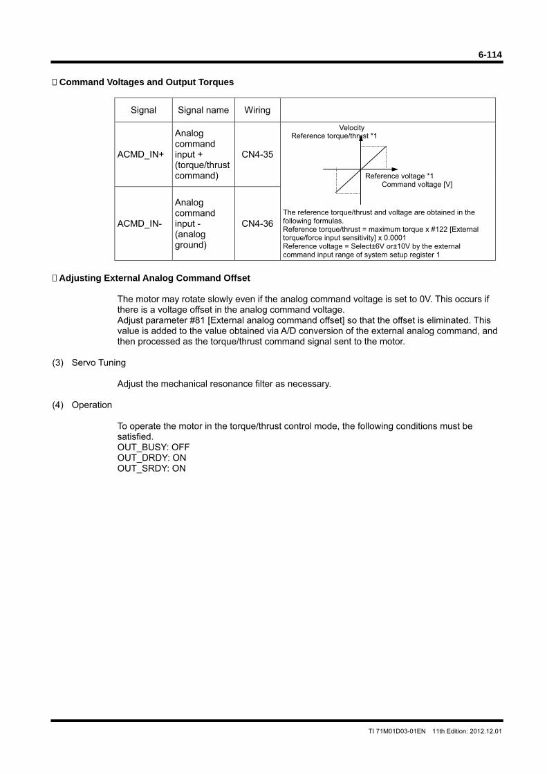
6-114
TI 71M01D03-01EN 11th Edition: 2012.12.01
Command Voltages and Output Torques
Signal Signal name Wiring
ACMD_IN+
Analog command input + (torque/thrust command)
CN4-35
Velocity The reference torque/thrust and voltage are obtained in the following formulas. Reference torque/thrust = maximum torque x #122 [External torque/force input sensitivity] x 0.0001 Reference voltage = Select±6V or±10V by the external command input range of system setup register 1
ACMD_IN-
Analog command input - (analog ground)
CN4-36
Adjusting External Analog Command Offset
The motor may rotate slowly even if the analog command voltage is set to 0V. This occurs if there is a voltage offset in the analog command voltage. Adjust parameter #81 [External analog command offset] so that the offset is eliminated. This value is added to the value obtained via A/D conversion of the external analog command, and then processed as the torque/thrust command signal sent to the motor.
(3) Servo Tuning
Adjust the mechanical resonance filter as necessary. (4) Operation
To operate the motor in the torque/thrust control mode, the following conditions must be satisfied. OUT_BUSY: OFF OUT_DRDY: ON OUT_SRDY: ON
Reference torque/thrust *1
Reference voltage *1 Command voltage [V]
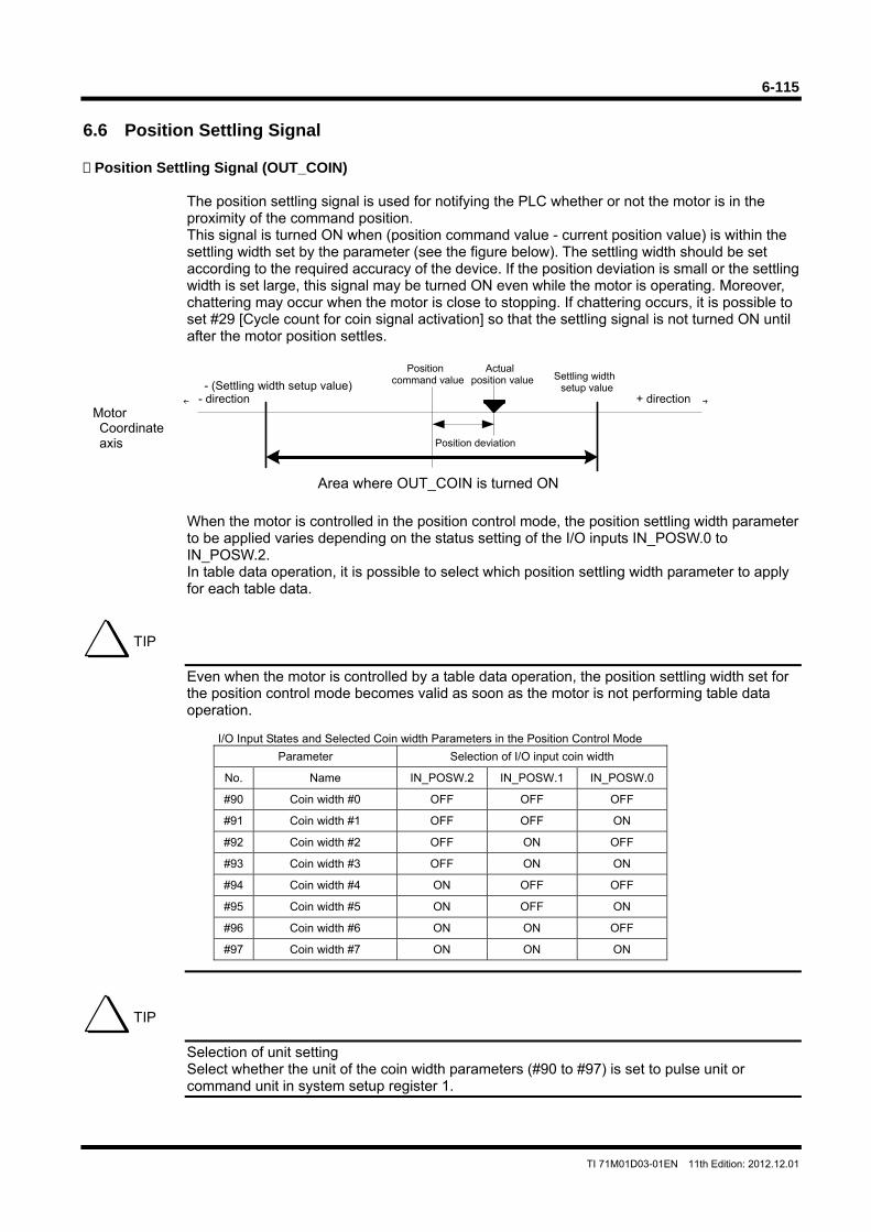
6-115
TI 71M01D03-01EN 11th Edition: 2012.12.01
6.6 Position Settling Signal Position Settling Signal (OUT_COIN)
The position settling signal is used for notifying the PLC whether or not the motor is in the proximity of the command position. This signal is turned ON when (position command value - current position value) is within the settling width set by the parameter (see the figure below). The settling width should be set according to the required accuracy of the device. If the position deviation is small or the settling width is set large, this signal may be turned ON even while the motor is operating. Moreover, chattering may occur when the motor is close to stopping. If chattering occurs, it is possible to set #29 [Cycle count for coin signal activation] so that the settling signal is not turned ON until after the motor position settles.
When the motor is controlled in the position control mode, the position settling width parameter to be applied varies depending on the status setting of the I/O inputs IN_POSW.0 to IN_POSW.2. In table data operation, it is possible to select which position settling width parameter to apply for each table data.
Even when the motor is controlled by a table data operation, the position settling width set for the position control mode becomes valid as soon as the motor is not performing table data operation.
I/O Input States and Selected Coin width Parameters in the Position Control Mode
Parameter Selection of I/O input coin width
No. Name IN_POSW.2 IN_POSW.1 IN_POSW.0
#90 Coin width #0 OFF OFF OFF
#91 Coin width #1 OFF OFF ON
#92 Coin width #2 OFF ON OFF
#93 Coin width #3 OFF ON ON
#94 Coin width #4 ON OFF OFF
#95 Coin width #5 ON OFF ON
#96 Coin width #6 ON ON OFF
#97 Coin width #7 ON ON ON
Selection of unit setting Select whether the unit of the coin width parameters (#90 to #97) is set to pulse unit or command unit in system setup register 1.
TIP
TIP
← →
Position command value Settling width
setup value- (Settling width setup value)
Area where OUT_COIN is turned ON
Actual position value
Position deviation
Motor Coordinate axis
- direction + direction
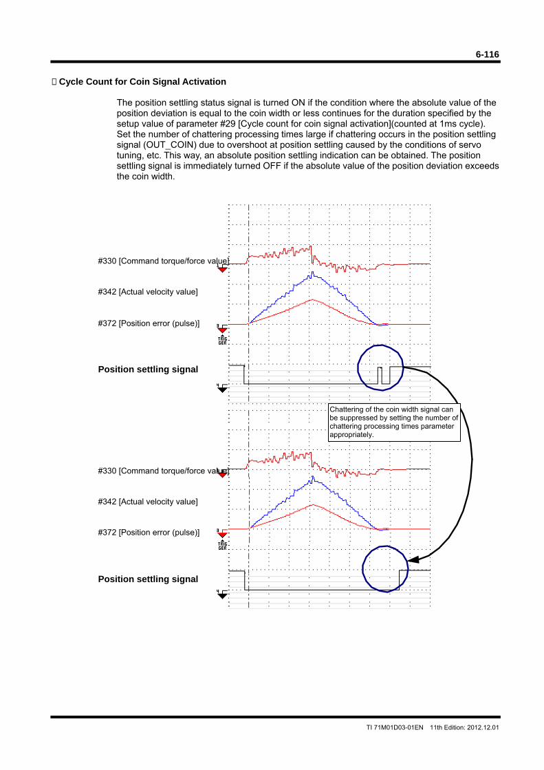
6-116
TI 71M01D03-01EN 11th Edition: 2012.12.01
Cycle Count for Coin Signal Activation
The position settling status signal is turned ON if the condition where the absolute value of the position deviation is equal to the coin width or less continues for the duration specified by the setup value of parameter #29 [Cycle count for coin signal activation](counted at 1ms cycle). Set the number of chattering processing times large if chattering occurs in the position settling signal (OUT_COIN) due to overshoot at position settling caused by the conditions of servo tuning, etc. This way, an absolute position settling indication can be obtained. The position settling signal is immediately turned OFF if the absolute value of the position deviation exceeds the coin width.
Chattering of the coin width signal can be suppressed by setting the number of chattering processing times parameter appropriately.
#330 [Command torque/force value]
#342 [Actual velocity value]
#372 [Position error (pulse)]
Position settling signal
#330 [Command torque/force value]
#342 [Actual velocity value]
#372 [Position error (pulse)]
Position settling signal
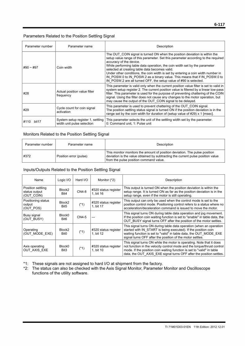
6-117
TI 71M01D03-01EN 11th Edition: 2012.12.01
Parameters Related to the Position Settling Signal
Parameter number Parameter name Description
#90 ~ #97 Coin width
The OUT_COIN signal is turned ON when the position deviation is within the setup value range of this parameter. Set this parameter according to the required accuracy of the device. While performing table data operation, the coin width set by the parameter selected at creating table data becomes valid. Under other conditions, the coin width is set by entering a coin width number in IN_POSW.0 to IN_POSW.2 as a binary value. This means that if IN_POSW.0 to IN_POSW.2 are all turned OFF, the setup value of #90 is selected.
#28 Actual position value filter frequency
This parameter is valid only when the current position value filter is set to valid in system setup register 2. The current position value is filtered by a linear low-pass filter. This parameter is used for the purpose of preventing chattering of the COIN signal. Using the filter does not cause any changes to the motor operation, but may cause the output of the OUT_COIN signal to be delayed.
#29 Cycle count for coin signal activation
This parameter is used to prevent chattering of the OUT_COIN signal. The position settling status signal is turned ON if the position deviation is in the range set by the coin width for duration of (setup value of #29) x 1 [msec].
#110 bit17 System setup register 1, settling width unit pulse selection
This parameter selects the unit of the settling width set by the parameter. 0: Command unit, 1: Pulse unit
Monitors Related to the Position Settling Signal
Parameter number Parameter name Description
#372 Position error (pulse) This monitor monitors the amount of position deviation. The pulse position deviation is the value obtained by subtracting the current pulse position value from the pulse position command value.
Inputs/Outputs Related to the Position Settling Signal
Name Logic I/O Hard I/O Monitor (*2) Description
Position settling status output (OUT_COIN)
Block2 Bit4
CN4-8 #320 status register 1, bit 16
This output is turned ON when the position deviation is within the setup range. It is turned ON as far as the position deviation is in the setup range, even if the motor is still operating.
Positioning status output (OUT_POS)
Block2 Bit5
(*1) #320 status register 1, bit 17
This output can only be used when the control mode is set to the position control mode. Positioning control refers to a status where no acceleration/deceleration command is issued to move the motor.
Busy signal (OUT_BUSY)
Block0 Bit6
CN4-5 --- This signal turns ON during table data operation and jog movement. If the position coin waiting function is set to "enable" in table data, the OUT_BUSY signal turns OFF after the position of the motor settles.
Operating (OUT_MODE_EXE)
Block2 Bit0
(*1) #320 status register 1, bit 12
This signal turns ON during table data operation (when an operation started with IN_START is being executed). If the position coin waiting function is set to "valid" in table data, the OUT_MODE_EXE signal turns OFF after the position of the motor settles.
Axis operating OUT_AXIS_EXE
Block0 Bit3
(*1) #320 status register 1, bit 10
This signal turns ON while the motor is operating. Note that it does not function in the velocity control mode and the torque/thrust control mode. If the position coin waiting function is set to "valid" in table data, the OUT_AXIS_EXE signal turns OFF after the position settles.
*1: These signals are not assigned to hard I/O at shipment from the factory. *2: The status can also be checked with the Axis Signal Monitor, Parameter Monitor and Oscilloscope
functions of the utility software.
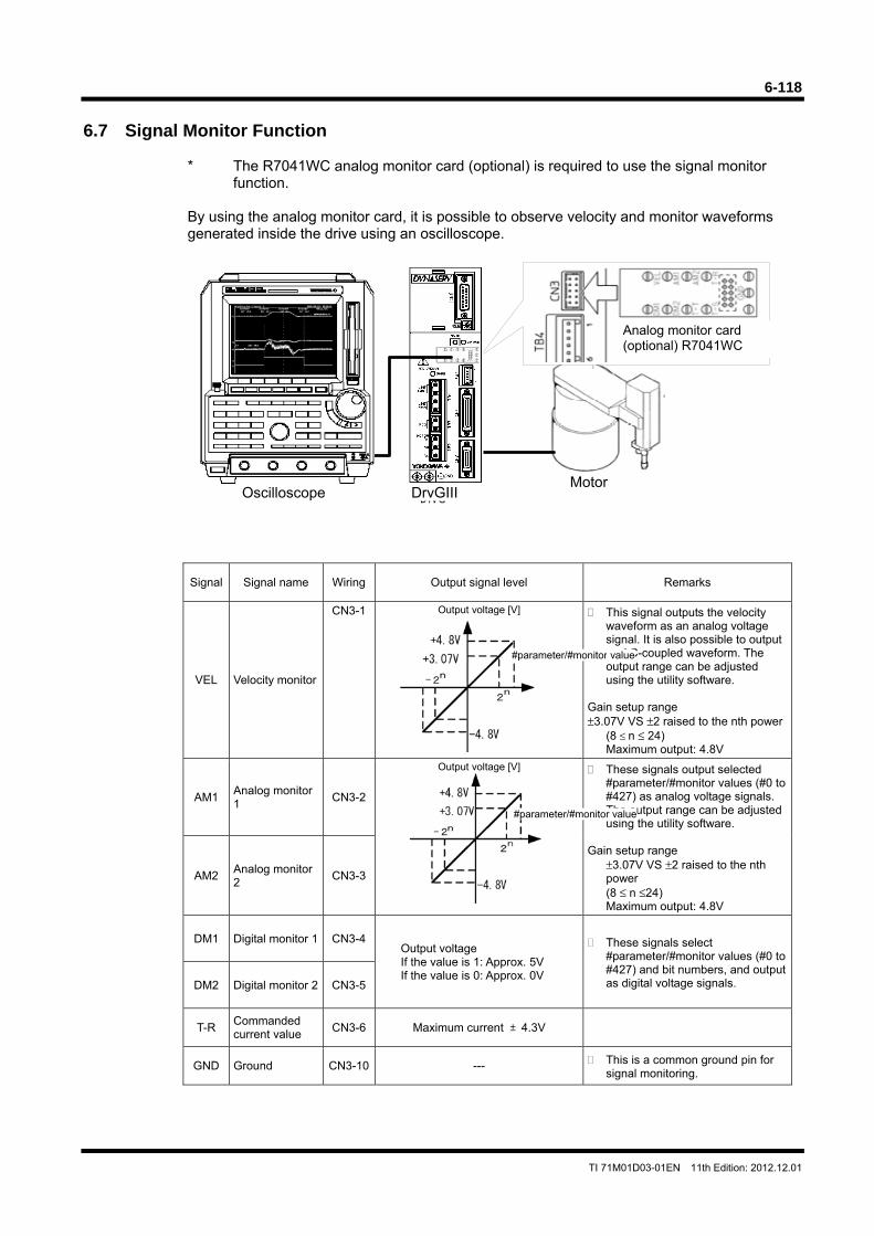
6-118
TI 71M01D03-01EN 11th Edition: 2012.12.01
6.7 Signal Monitor Function
* The R7041WC analog monitor card (optional) is required to use the signal monitor function.
By using the analog monitor card, it is possible to observe velocity and monitor waveforms generated inside the drive using an oscilloscope.
Signal Signal name Wiring Output signal level Remarks
VEL Velocity monitor
CN3-1 Output voltage [V]
This signal outputs the velocity waveform as an analog voltage signal. It is also possible to output an AC-coupled waveform. The output range can be adjusted using the utility software.
Gain setup range ±3.07V VS ±2 raised to the nth power
(8 ≤ n ≤ 24) Maximum output: 4.8V
AM1 Analog monitor 1
CN3-2
Output voltage [V]
These signals output selected #parameter/#monitor values (#0 to #427) as analog voltage signals. The output range can be adjusted using the utility software.
Gain setup range
±3.07V VS ±2 raised to the nth power (8 ≤ n ≤24) Maximum output: 4.8V
AM2 Analog monitor 2
CN3-3
DM1 Digital monitor 1 CN3-4Output voltage If the value is 1: Approx. 5V If the value is 0: Approx. 0V
These signals select #parameter/#monitor values (#0 to #427) and bit numbers, and output as digital voltage signals. DM2 Digital monitor 2 CN3-5
T-R Commanded current value
CN3-6 Maximum current ±4.3V
GND Ground CN3-10 --- This is a common ground pin for signal monitoring.
#parameter/#monitor value
#parameter/#monitor value
DrvG
Oscilloscope DrvGIIIMotor
Analog monitor card (optional) R7041WC
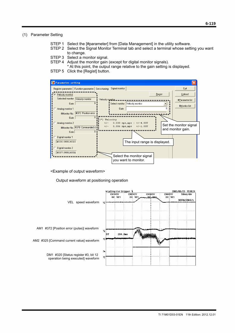
6-119
TI 71M01D03-01EN 11th Edition: 2012.12.01
(1) Parameter Setting
STEP 1 Select the [#parameter] from [Data Management] in the utility software. STEP 2 Select the Signal Monitor Terminal tab and select a terminal whose setting you want
to change. STEP 3 Select a monitor signal. STEP 4 Adjust the monitor gain (except for digital monitor signals). * At this point, the output range relative to the gain setting is displayed. STEP 5 Click the [Regist] button.
<Example of output waveform>
Output waveform at positioning operation
Set the monitor signal and monitor gain.
The input range is displayed.
Select the monitor signal you want to monitor.
VEL speed waveform
AM1 #372 [Position error (pulse)] waveform
DM1 #320 [Status register #3, bit 12 operation being executed] waveform
AM2 #325 [Command current value] waveform
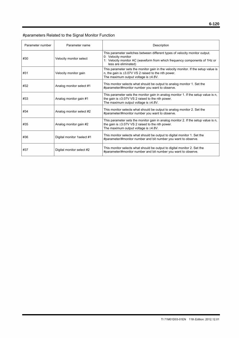
6-120
TI 71M01D03-01EN 11th Edition: 2012.12.01
#parameters Related to the Signal Monitor Function
Parameter number Parameter name Description
#30 Velocity monitor select
This parameter switches between different types of velocity monitor output. 0: Velocity monitor 1: Velocity monitor AC (waveform from which frequency components of 1Hz or
less are eliminated)
#31 Velocity monitor gain This parameter sets the monitor gain in the velocity monitor. If the setup value is n, the gain is ±3.07V VS 2 raised to the nth power. The maximum output voltage is ±4.8V.
#32 Analog monitor select #1 This monitor selects what should be output to analog monitor 1. Set the #parameter/#monitor number you want to observe.
#33 Analog monitor gain #1 This parameter sets the monitor gain in analog monitor 1. If the setup value is n, the gain is ±3.07V VS 2 raised to the nth power. The maximum output voltage is ±4.8V.
#34 Analog monitor select #2 This monitor selects what should be output to analog monitor 2. Set the #parameter/#monitor number you want to observe.
#35 Analog monitor gain #2 This parameter sets the monitor gain in analog monitor 2. If the setup value is n, the gain is ±3.07V VS 2 raised to the nth power. The maximum output voltage is ±4.8V.
#36 Digital monitor 1select #1 This monitor selects what should be output to digital monitor 1. Set the #parameter/#monitor number and bit number you want to observe.
#37 Digital monitor select #2 This monitor selects what should be output to digital monitor 2. Set the #parameter/#monitor number and bit number you want to observe.
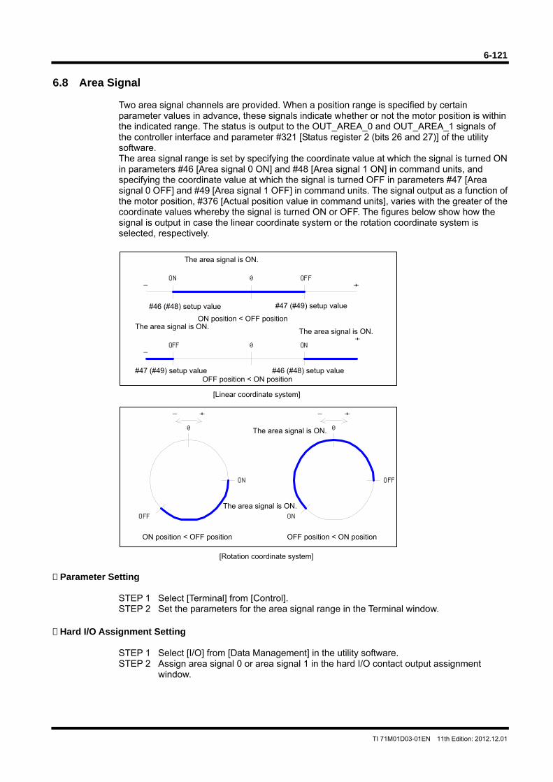
6-121
TI 71M01D03-01EN 11th Edition: 2012.12.01
6.8 Area Signal
Two area signal channels are provided. When a position range is specified by certain parameter values in advance, these signals indicate whether or not the motor position is within the indicated range. The status is output to the OUT_AREA_0 and OUT_AREA_1 signals of the controller interface and parameter #321 [Status register 2 (bits 26 and 27)] of the utility software. The area signal range is set by specifying the coordinate value at which the signal is turned ON in parameters #46 [Area signal 0 ON] and #48 [Area signal 1 ON] in command units, and specifying the coordinate value at which the signal is turned OFF in parameters #47 [Area signal 0 OFF] and #49 [Area signal 1 OFF] in command units. The signal output as a function of the motor position, #376 [Actual position value in command units], varies with the greater of the coordinate values whereby the signal is turned ON or OFF. The figures below show how the signal is output in case the linear coordinate system or the rotation coordinate system is selected, respectively.
Parameter Setting
STEP 1 Select [Terminal] from [Control]. STEP 2 Set the parameters for the area signal range in the Terminal window.
Hard I/O Assignment Setting
STEP 1 Select [I/O] from [Data Management] in the utility software. STEP 2 Assign area signal 0 or area signal 1 in the hard I/O contact output assignment
window.
0
+-
ON
OFF
0
+-
OFF
ON
0- +
ON OFF
0-
+OFF ON
[Rotation coordinate system]
The area signal is ON.
ON position < OFF position
The area signal is ON.
OFF position < ON position
[Linear coordinate system]
ON position < OFF position
The area signal is ON.
OFF position < ON position
The area signal is ON.The area signal is ON.
#47 (#49) setup value#46 (#48) setup value
#47 (#49) setup value #46 (#48) setup value
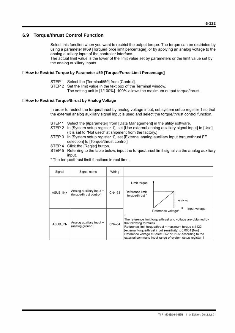
6-122
TI 71M01D03-01EN 11th Edition: 2012.12.01
6.9 Torque/thrust Control Function
Select this function when you want to restrict the output torque. The torque can be restricted by using a parameter (#59 [Torque/Force limit percentage]) or by applying an analog voltage to the analog auxiliary input of the controller interface. The actual limit value is the lower of the limit value set by parameters or the limit value set by the analog auxiliary inputs.
How to Restrict Torque by Parameter #59 [Torque/Force Limit Percentage]
STEP 1 Select the [Terminal#59] from [Control]. STEP 2 Set the limit value in the text box of the Terminal window.
The setting unit is [1/100%]. 100% allows the maximum output torque/thrust. How to Restrict Torque/thrust by Analog Voltage
In order to restrict the torque/thrust by analog voltage input, set system setup register 1 so that the external analog auxiliary signal input is used and select the torque/thrust control function.
STEP 1 Select the [#parameter] from [Data Management] in the utility software. STEP 2 In [System setup register 1], set [Use external analog auxiliary signal input] to [Use].
(It is set to "Not used" at shipment from the factory.) STEP 3 In [System setup register 1], set [External analog auxiliary input torque/thrust FF
selection] to [Torque/thrust control]. STEP 4 Click the [Regist] button. STEP 5 Referring to the table below, input the torque/thrust limit signal via the analog auxiliary
input. * The torque/thrust limit functions in real time.
Signal Signal name Wiring
ASUB_IN+ Analog auxiliary input + (torque/thrust control)
CN4-33
* The reference limit torque/thrust and voltage are obtained by the following formulas. Reference limit torque/thrust = maximum torque x #122 [external torque/thrust input sensitivity] x 0.0001 [Nm] Reference voltage = Select ±6V or ±10V according to the external command input range of system setup register 1
ASUB_IN- Analog auxiliary input + (analog ground)
CN4-34
Input voltageReference voltage*
Reference limittorque/thrust *
Limit torque
+6V/+10V
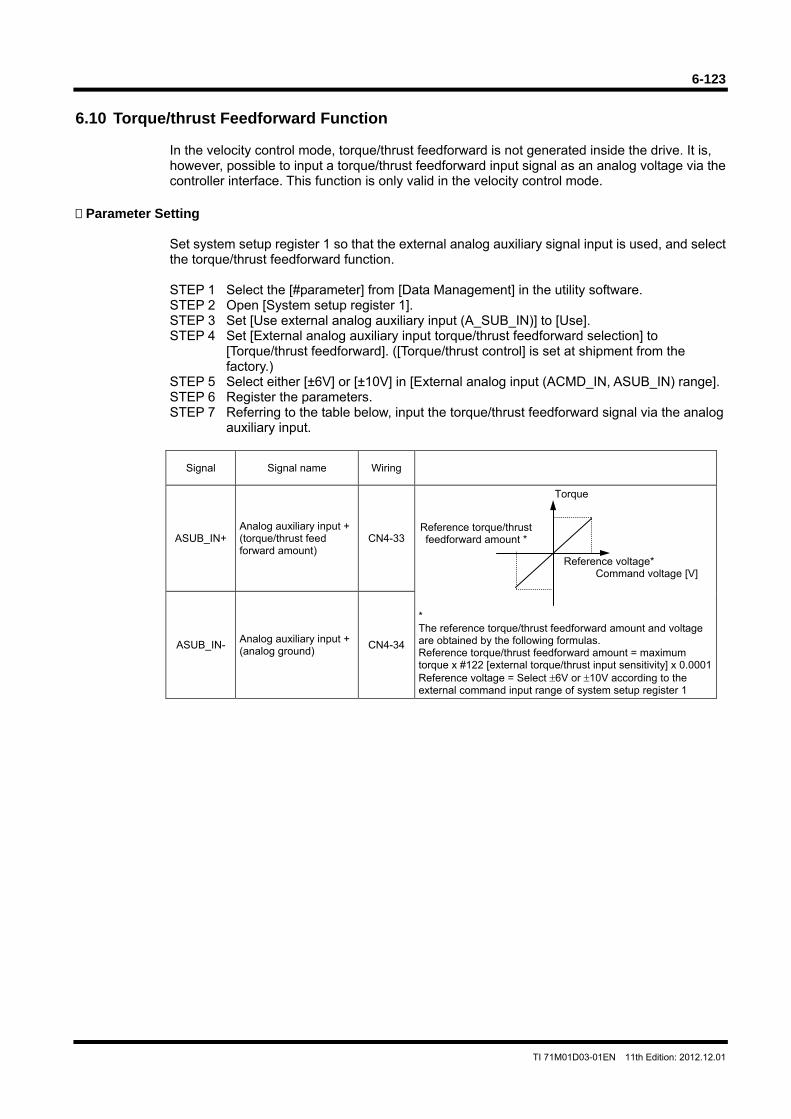
6-123
TI 71M01D03-01EN 11th Edition: 2012.12.01
6.10 Torque/thrust Feedforward Function
In the velocity control mode, torque/thrust feedforward is not generated inside the drive. It is, however, possible to input a torque/thrust feedforward input signal as an analog voltage via the controller interface. This function is only valid in the velocity control mode.
Parameter Setting
Set system setup register 1 so that the external analog auxiliary signal input is used, and select the torque/thrust feedforward function.
STEP 1 Select the [#parameter] from [Data Management] in the utility software. STEP 2 Open [System setup register 1]. STEP 3 Set [Use external analog auxiliary input (A_SUB_IN)] to [Use]. STEP 4 Set [External analog auxiliary input torque/thrust feedforward selection] to
[Torque/thrust feedforward]. ([Torque/thrust control] is set at shipment from the factory.)
STEP 5 Select either [±6V] or [±10V] in [External analog input (ACMD_IN, ASUB_IN) range]. STEP 6 Register the parameters. STEP 7 Referring to the table below, input the torque/thrust feedforward signal via the analog
auxiliary input.
Signal Signal name Wiring
ASUB_IN+ Analog auxiliary input + (torque/thrust feed forward amount)
CN4-33
* The reference torque/thrust feedforward amount and voltage are obtained by the following formulas. Reference torque/thrust feedforward amount = maximum torque x #122 [external torque/thrust input sensitivity] x 0.0001 Reference voltage = Select ±6V or ±10V according to the external command input range of system setup register 1
ASUB_IN- Analog auxiliary input + (analog ground)
CN4-34
Reference voltage* Command voltage [V]
Reference torque/thrust feedforward amount *
Torque
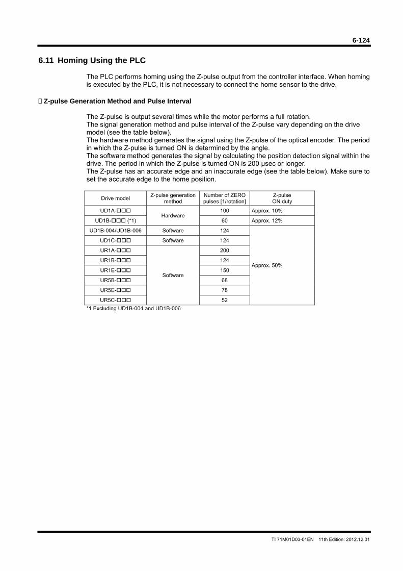
6-124
TI 71M01D03-01EN 11th Edition: 2012.12.01
6.11 Homing Using the PLC
The PLC performs homing using the Z-pulse output from the controller interface. When homing is executed by the PLC, it is not necessary to connect the home sensor to the drive.
Z-pulse Generation Method and Pulse Interval
The Z-pulse is output several times while the motor performs a full rotation. The signal generation method and pulse interval of the Z-pulse vary depending on the drive model (see the table below). The hardware method generates the signal using the Z-pulse of the optical encoder. The period in which the Z-pulse is turned ON is determined by the angle. The software method generates the signal by calculating the position detection signal within the drive. The period in which the Z-pulse is turned ON is 200 μsec or longer. The Z-pulse has an accurate edge and an inaccurate edge (see the table below). Make sure to set the accurate edge to the home position.
Drive model Z-pulse generation
method Number of ZERO pulses [1/rotation]
Z-pulse ON duty
UD1A- Hardware
100 Approx. 10%
UD1B- (*1) 60 Approx. 12%
UD1B-004/UD1B-006 Software 124
Approx. 50%
UD1C- Software 124
UR1A-
Software
200
UR1B- 124
UR1E- 150
UR5B- 68
UR5E- 78
UR5C- 52
*1 Excluding UD1B-004 and UD1B-006
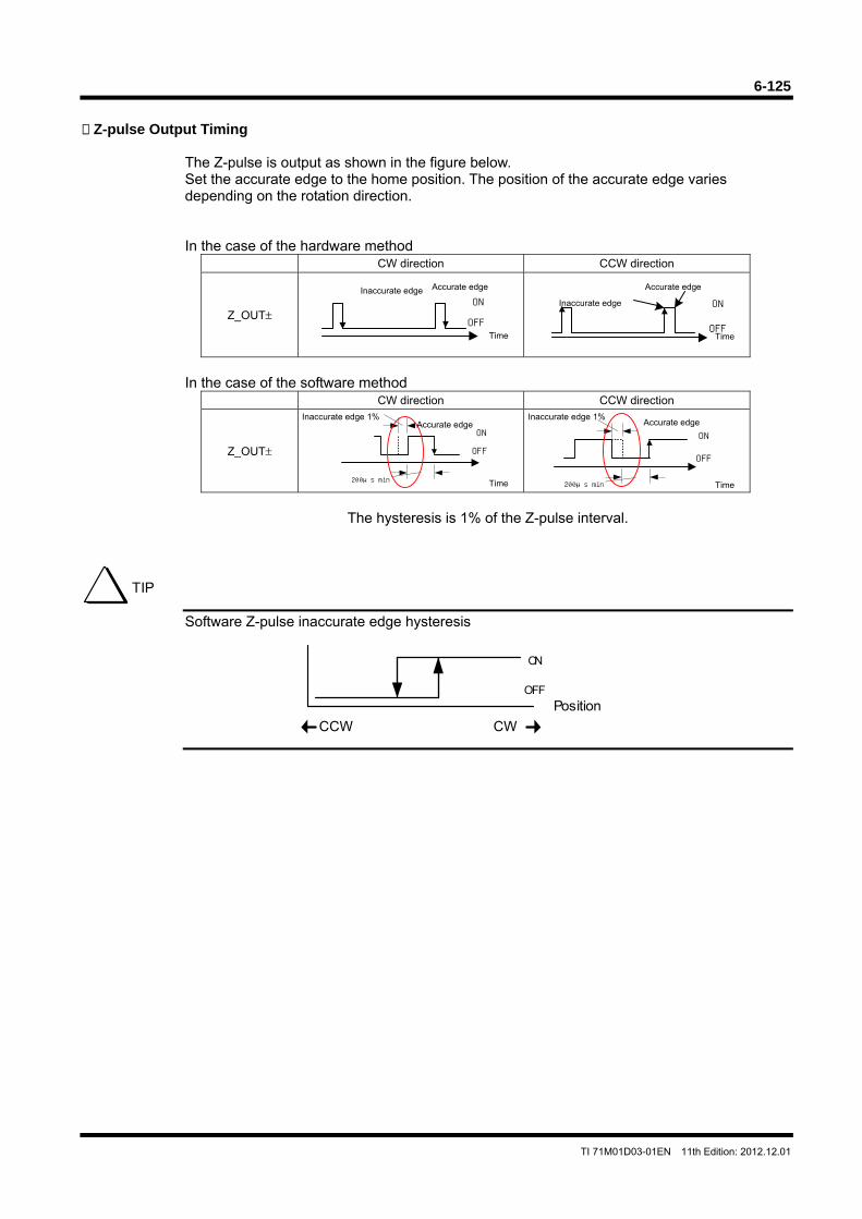
6-125
TI 71M01D03-01EN 11th Edition: 2012.12.01
ON
OFF
ON
OFF
ON
OFF
200μs min
ON
OFF
200μs min
Z-pulse Output Timing
The Z-pulse is output as shown in the figure below. Set the accurate edge to the home position. The position of the accurate edge varies depending on the rotation direction.
In the case of the hardware method
CW direction CCW direction
Z_OUT±
Inaccurate edge
Time
Inaccurate edge
Time
In the case of the software method
CW direction CCW direction
Z_OUT±
Inaccurate edge 1%
Time
Inaccurate edge 1%
Time
The hysteresis is 1% of the Z-pulse interval.
Software Z-pulse inaccurate edge hysteresis
TIP
CWCCW
ON
OFF
Position
Accurate edge
Accurate edge
Accurate edge
Accurate edge
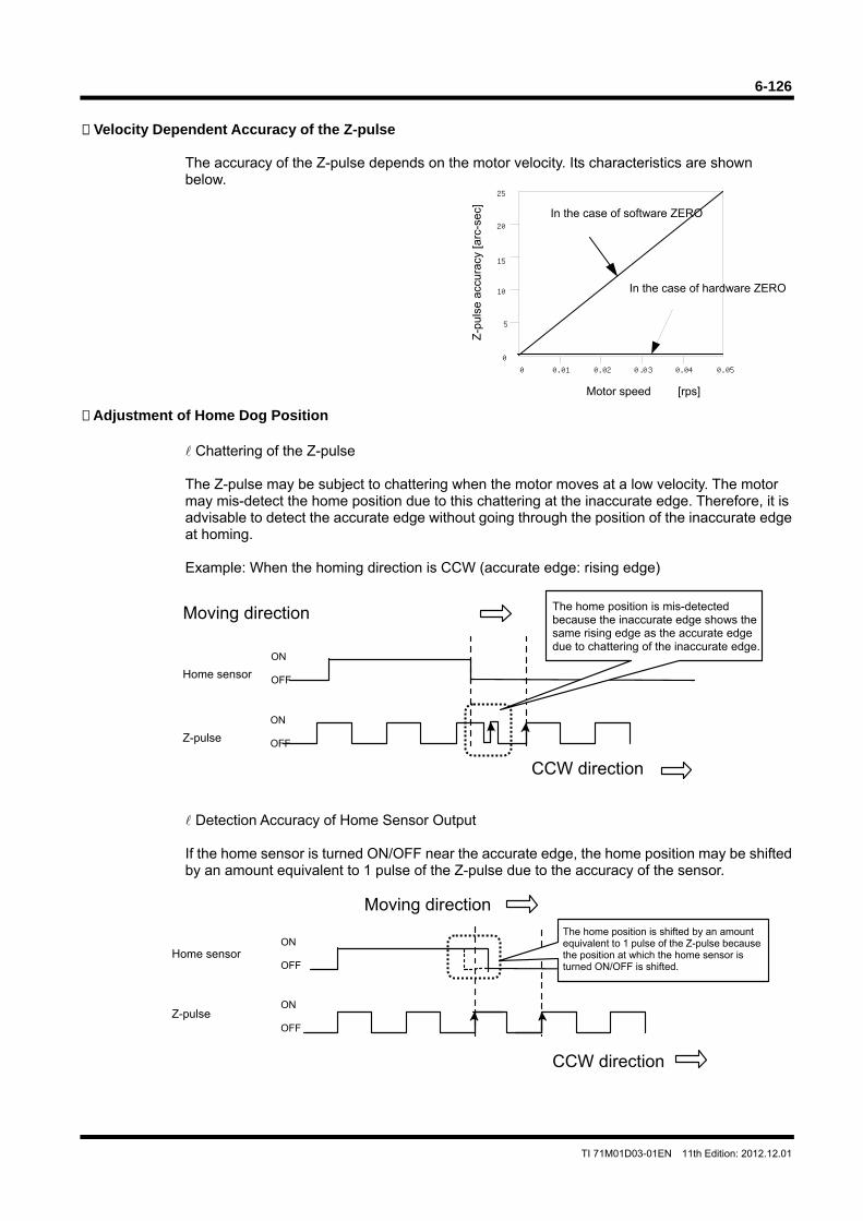
6-126
TI 71M01D03-01EN 11th Edition: 2012.12.01
0 0.01 0.02 0.03 0.04 0.05
10
15
20
25
5
0
Velocity Dependent Accuracy of the Z-pulse
The accuracy of the Z-pulse depends on the motor velocity. Its characteristics are shown below.
Adjustment of Home Dog Position
Chattering of the Z-pulse The Z-pulse may be subject to chattering when the motor moves at a low velocity. The motor may mis-detect the home position due to this chattering at the inaccurate edge. Therefore, it is advisable to detect the accurate edge without going through the position of the inaccurate edge at homing. Example: When the homing direction is CCW (accurate edge: rising edge)
Detection Accuracy of Home Sensor Output If the home sensor is turned ON/OFF near the accurate edge, the home position may be shifted by an amount equivalent to 1 pulse of the Z-pulse due to the accuracy of the sensor.
Motor speed [rps]
In the case of hardware ZERO
In the case of software ZERO
Z-p
ulse
acc
urac
y [a
rc-s
ec]
CCW direction
Z-pulse
Moving direction
Home sensor
The home position is shifted by an amount equivalent to 1 pulse of the Z-pulse becausethe position at which the home sensor is turned ON/OFF is shifted.
ON OFF
ON OFF
Home sensor
CCW direction
Z-pulse
Moving direction
ON OFF
ON OFF
The home position is mis-detected because the inaccurate edge shows the same rising edge as the accurate edge due to chattering of the inaccurate edge.
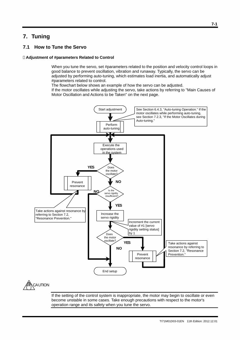
7-1
TI71M01D03-01EN 11th Edition: 2012.12.01
7. Tuning 7.1 How to Tune the Servo Adjustment of #parameters Related to Control
When you tune the servo, set #parameters related to the position and velocity control loops in good balance to prevent oscillation, vibration and runaway. Typically, the servo can be adjusted by performing auto-tuning, which estimates load inertia, and automatically adjust #parameters related to control. The flowchart below shows an example of how the servo can be adjusted. If the motor oscillates while adjusting the servo, take actions by referring to "Main Causes of Motor Oscillation and Actions to be Taken" on the next page.
If the setting of the control system is inappropriate, the motor may begin to oscillate or even become unstable in some cases. Take enough precautions with respect to the motor's operation range and its safety when you tune the servo.
YES
NO
NO
YES
YES
NO
CAUTION
Start adjustment
End setup
Is the servo rigidity insufficient?
Increase the servo rigidity
Prevent resonance
Prevent resonance
Perform auto-tuning
Increment the current value of #1 [servo rigidity setting status] by 1
See Section 6.4.3, "Auto-tuning Operation." If themotor oscillates while performing auto-tuning, see Section 7.2.3, "If the Motor Oscillates during Auto-tuning."
Take actions against resonance by referring to Section 7.2, "Resonance Prevention."
Take actions against resonance by referring to Section 7.2, "Resonance Prevention."
Execute the operations used
in the system
Does the motoroscillate?
Does the motor oscillate?
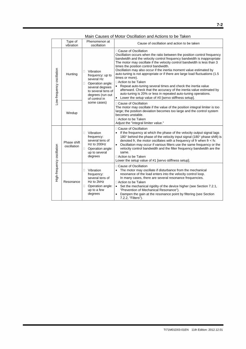
7-2
TI71M01D03-01EN 11th Edition: 2012.12.01
Main Causes of Motor Oscillation and Actions to be Taken
Type of vibration
Phenomenon at oscillation
Cause of oscillation and action to be taken
Low
-fre
quen
cy o
scill
atio
n
Hunting Vibration
frequency: up to several Hz
Operation angle: several degrees to several tens of degrees (run out of control in some cases)
Cause of Oscillation Oscillation occurs when the ratio between the position control frequency bandwidth and the velocity control frequency bandwidth is inappropriate The motor may oscillate if the velocity control bandwidth is less than 3 times the position control bandwidth. Oscillation may also occur if the inertia moment value estimated by auto-tuning is not appropriate or if there are large load fluctuations (1.5 times or more). Action to be Taken
• Repeat auto-tuning several times and check the inertia value afterward. Check that the accuracy of the inertia value estimated by auto-tuning is 20% or less in repeated auto-tuning operations.
• Lower the setup value of #0 [servo stiffness setup].
Windup
Cause of Oscillation The motor may oscillate if the value of the position integral limiter is too large; the position deviation becomes too large and the control system becomes unstable. Action to be Taken
Adjust the "integral limiter value."
Hig
h-fr
eque
ncy
osci
llatio
n
Phase shift oscillation
Vibration frequency: several tens of Hz to 200Hz
Operation angle: up to several degrees
Cause of Oscillation • If the frequency at which the phase of the velocity output signal lags
180° behind the phase of the velocity input signal (180° phase shift) is denoted fr, the motor oscillates with a frequency of fr when fr < fv.
• Oscillation may occur if various filters use the same frequency or the velocity control bandwidth and the filter frequency bandwidth are the same.
Action to be Taken Lower the setup value of #1 [servo stiffness setup].
Resonance
Vibration frequency: several tens of Hz to 2kHz
Operation angle: up to a few degrees
Cause of Oscillation • The motor may oscillate if disturbance from the mechanical
resonance of the load enters into the velocity control loop. In many cases, there are several resonance frequencies.
Action to be Taken • Set the mechanical rigidity of the device higher (see Section 7.2.1,
"Prevention of Mechanical Resonance"). • Dampen the gain at the resonance point by filtering (see Section
7.2.2, "Filters").
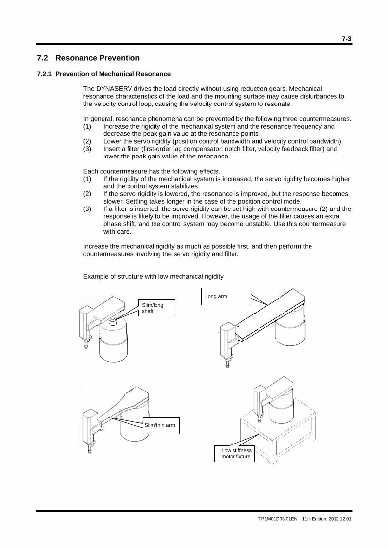
7-3
TI71M01D03-01EN 11th Edition: 2012.12.01
7.2 Resonance Prevention 7.2.1 Prevention of Mechanical Resonance
The DYNASERV drives the load directly without using reduction gears. Mechanical resonance characteristics of the load and the mounting surface may cause disturbances to the velocity control loop, causing the velocity control system to resonate. In general, resonance phenomena can be prevented by the following three countermeasures. (1) Increase the rigidity of the mechanical system and the resonance frequency and
decrease the peak gain value at the resonance points. (2) Lower the servo rigidity (position control bandwidth and velocity control bandwidth). (3) Insert a filter (first-order lag compensator, notch filter, velocity feedback filter) and
lower the peak gain value of the resonance. Each countermeasure has the following effects. (1) If the rigidity of the mechanical system is increased, the servo rigidity becomes higher
and the control system stabilizes. (2) If the servo rigidity is lowered, the resonance is improved, but the response becomes
slower. Settling takes longer in the case of the position control mode. (3) If a filter is inserted, the servo rigidity can be set high with countermeasure (2) and the
response is likely to be improved. However, the usage of the filter causes an extra phase shift, and the control system may become unstable. Use this countermeasure with care.
Increase the mechanical rigidity as much as possible first, and then perform the countermeasures involving the servo rigidity and filter.
Example of structure with low mechanical rigidity
Slim/long shaft
Long arm
Slim/thin arm
Low stiffness motor fixture
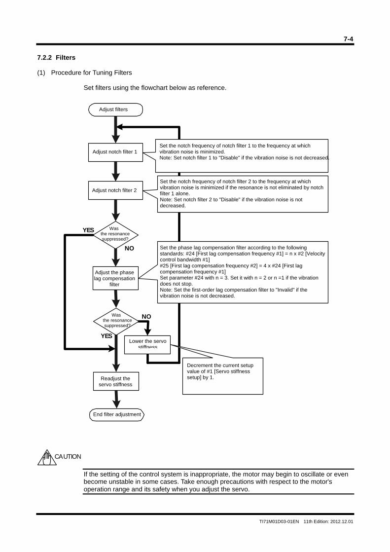
7-4
TI71M01D03-01EN 11th Edition: 2012.12.01
7.2.2 Filters (1) Procedure for Tuning Filters
Set filters using the flowchart below as reference.
If the setting of the control system is inappropriate, the motor may begin to oscillate or even become unstable in some cases. Take enough precautions with respect to the motor's operation range and its safety when you adjust the servo.
YES
NO
NO
YES
CAUTION
Set the notch frequency of notch filter 2 to the frequency at which vibration noise is minimized if the resonance is not eliminated by notch filter 1 alone. Note: Set notch filter 2 to "Disable" if the vibration noise is not decreased.
Adjust notch filter 1
Adjust the phase lag compensation
filter
Set the notch frequency of notch filter 1 to the frequency at which vibration noise is minimized. Note: Set notch filter 1 to "Disable" if the vibration noise is not decreased.
Adjust notch filter 2
Set the phase lag compensation filter according to the following standards: #24 [First lag compensation frequency #1] = n x #2 [Velocity control bandwidth #1] #25 [First lag compensation frequency #2] = 4 x #24 [First lag compensation frequency #1] Set parameter #24 with n = 3. Set it with n = 2 or n =1 if the vibration does not stop. Note: Set the first-order lag compensation filter to "Invalid" if the vibration noise is not decreased.
Was the resonance suppressed?
Lower the servo stiffness
Decrement the current setup value of #1 [Servo stiffness setup] by 1.
End filter adjustment
Readjust the servo stiffness
Adjust filters
Was the resonance suppressed?
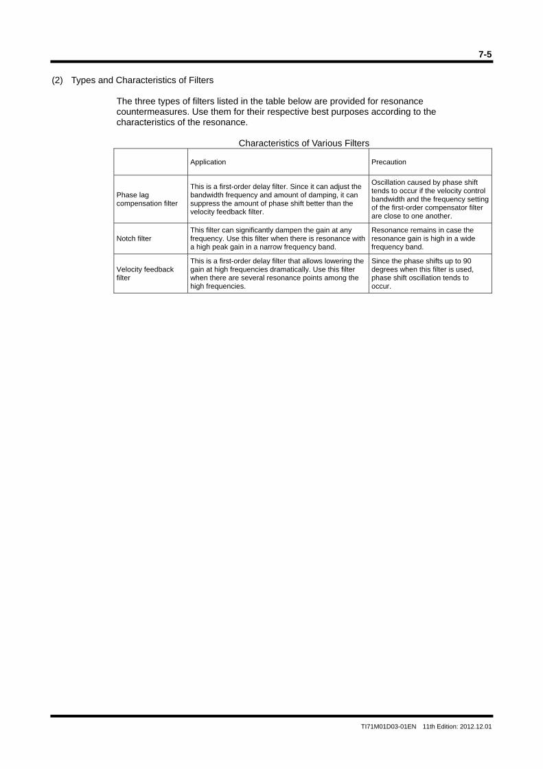
7-5
TI71M01D03-01EN 11th Edition: 2012.12.01
(2) Types and Characteristics of Filters
The three types of filters listed in the table below are provided for resonance countermeasures. Use them for their respective best purposes according to the characteristics of the resonance.
Characteristics of Various Filters
Application Precaution
Phase lag compensation filter
This is a first-order delay filter. Since it can adjust the bandwidth frequency and amount of damping, it can suppress the amount of phase shift better than the velocity feedback filter.
Oscillation caused by phase shift tends to occur if the velocity control bandwidth and the frequency setting of the first-order compensator filter are close to one another.
Notch filter This filter can significantly dampen the gain at any frequency. Use this filter when there is resonance with a high peak gain in a narrow frequency band.
Resonance remains in case the resonance gain is high in a wide frequency band.
Velocity feedback filter
This is a first-order delay filter that allows lowering the gain at high frequencies dramatically. Use this filter when there are several resonance points among the high frequencies.
Since the phase shifts up to 90 degrees when this filter is used, phase shift oscillation tends to occur.
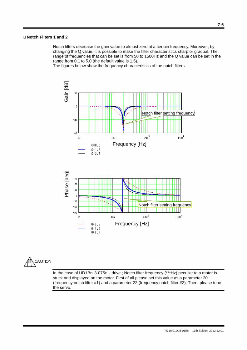
7-6
TI71M01D03-01EN 11th Edition: 2012.12.01
Notch Filters 1 and 2
Notch filters decrease the gain value to almost zero at a certain frequency. Moreover, by changing the Q value, it is possible to make the filter characteristics sharp or gradual. The range of frequencies that can be set is from 50 to 1500Hz and the Q value can be set in the range from 0.1 to 5.0 (the default value is 1.5). The figures below show the frequency characteristics of the notch filters.
In the case of UD1B3-075- drive ; Notch filter frequency (***Hz) peculiar to a motor is stuck and displayed on the motor. First of all please set this value as a parameter 20 (frequency notch filter #1) and a parameter 22 (frequency notch filter #2). Then, please tune the servo.
Gai
n [d
B]
Frequency [Hz]
Frequency [Hz]
Pha
se [d
eg]
Notch filter setting frequency
Notch filter setting frequency
CAUTION
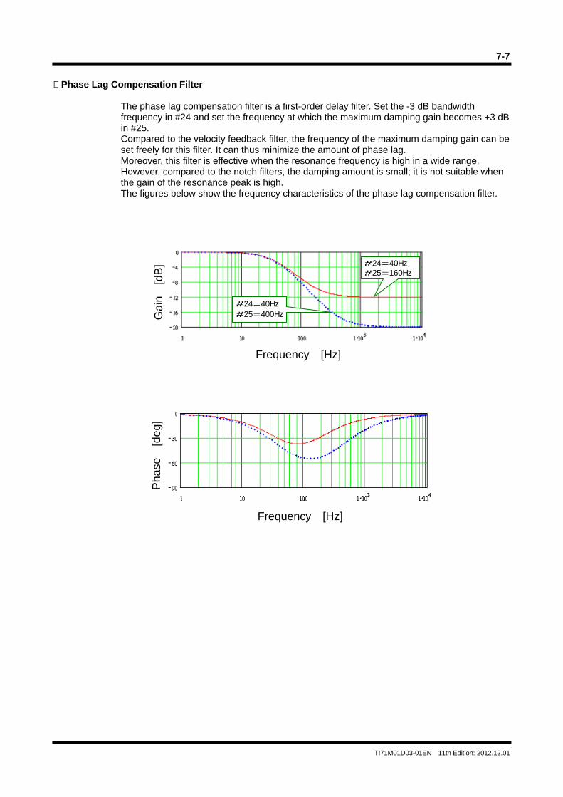
7-7
TI71M01D03-01EN 11th Edition: 2012.12.01
Phase Lag Compensation Filter
The phase lag compensation filter is a first-order delay filter. Set the -3 dB bandwidth frequency in #24 and set the frequency at which the maximum damping gain becomes +3 dB in #25. Compared to the velocity feedback filter, the frequency of the maximum damping gain can be set freely for this filter. It can thus minimize the amount of phase lag. Moreover, this filter is effective when the resonance frequency is high in a wide range. However, compared to the notch filters, the damping amount is small; it is not suitable when the gain of the resonance peak is high. The figures below show the frequency characteristics of the phase lag compensation filter.
#24=40Hz#25=160Hz
#24=40Hz#25=400Hz
Frequency [Hz]
Gai
n [
dB]
Frequency [Hz]
Pha
se
[deg
]
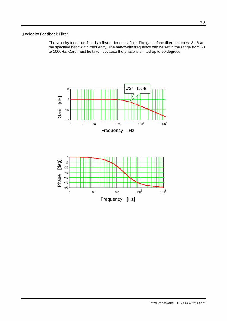
7-8
TI71M01D03-01EN 11th Edition: 2012.12.01
Velocity Feedback Filter
The velocity feedback filter is a first-order delay filter. The gain of the filter becomes -3 dB at the specified bandwidth frequency. The bandwidth frequency can be set in the range from 50 to 1000Hz. Care must be taken because the phase is shifted up to 90 degrees.
#27=100Hz
Gai
n [
dB]
Frequency [Hz]
Frequency [Hz]
Pha
se
[deg
]
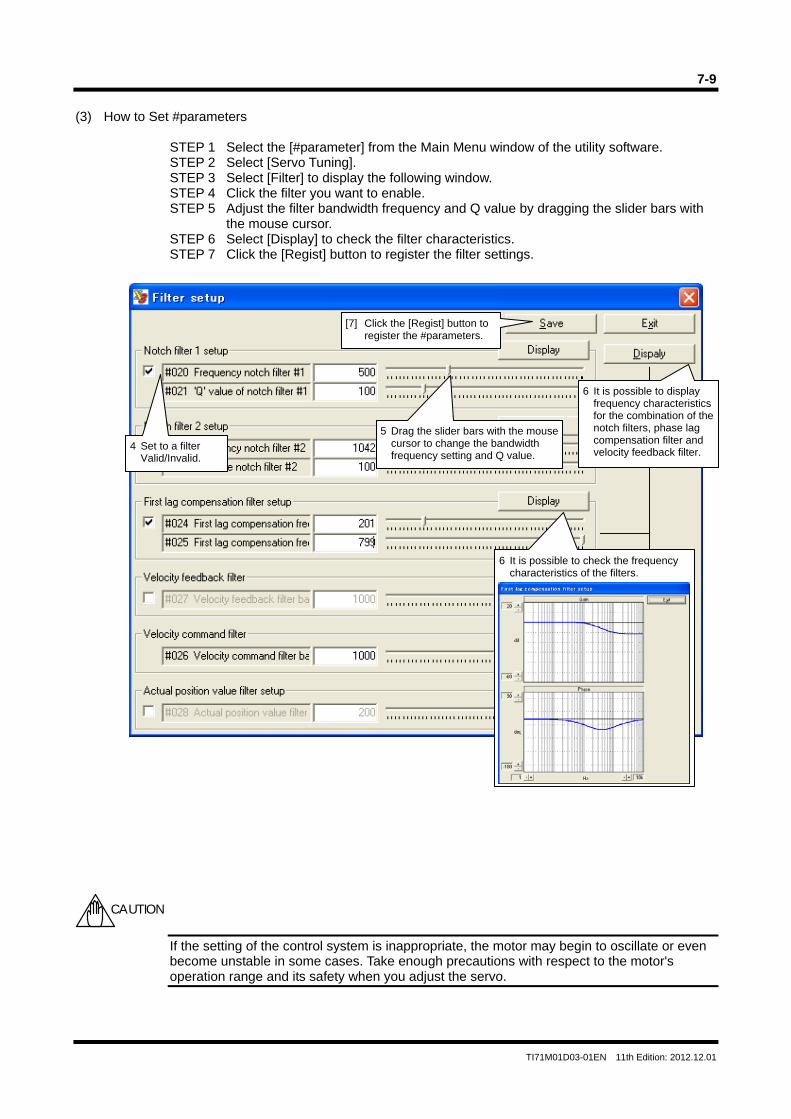
7-9
TI71M01D03-01EN 11th Edition: 2012.12.01
(3) How to Set #parameters
STEP 1 Select the [#parameter] from the Main Menu window of the utility software. STEP 2 Select [Servo Tuning]. STEP 3 Select [Filter] to display the following window. STEP 4 Click the filter you want to enable. STEP 5 Adjust the filter bandwidth frequency and Q value by dragging the slider bars with
the mouse cursor. STEP 6 Select [Display] to check the filter characteristics. STEP 7 Click the [Regist] button to register the filter settings.
If the setting of the control system is inappropriate, the motor may begin to oscillate or even become unstable in some cases. Take enough precautions with respect to the motor's operation range and its safety when you adjust the servo.
[7] Click the [Regist] button to register the #parameters.
4 Set to a filter Valid/Invalid.
6 It is possible to display frequency characteristics for the combination of the notch filters, phase lag compensation filter and velocity feedback filter.
5 Drag the slider bars with the mouse cursor to change the bandwidth frequency setting and Q value.
6 It is possible to check the frequency characteristics of the filters.
CAUTION
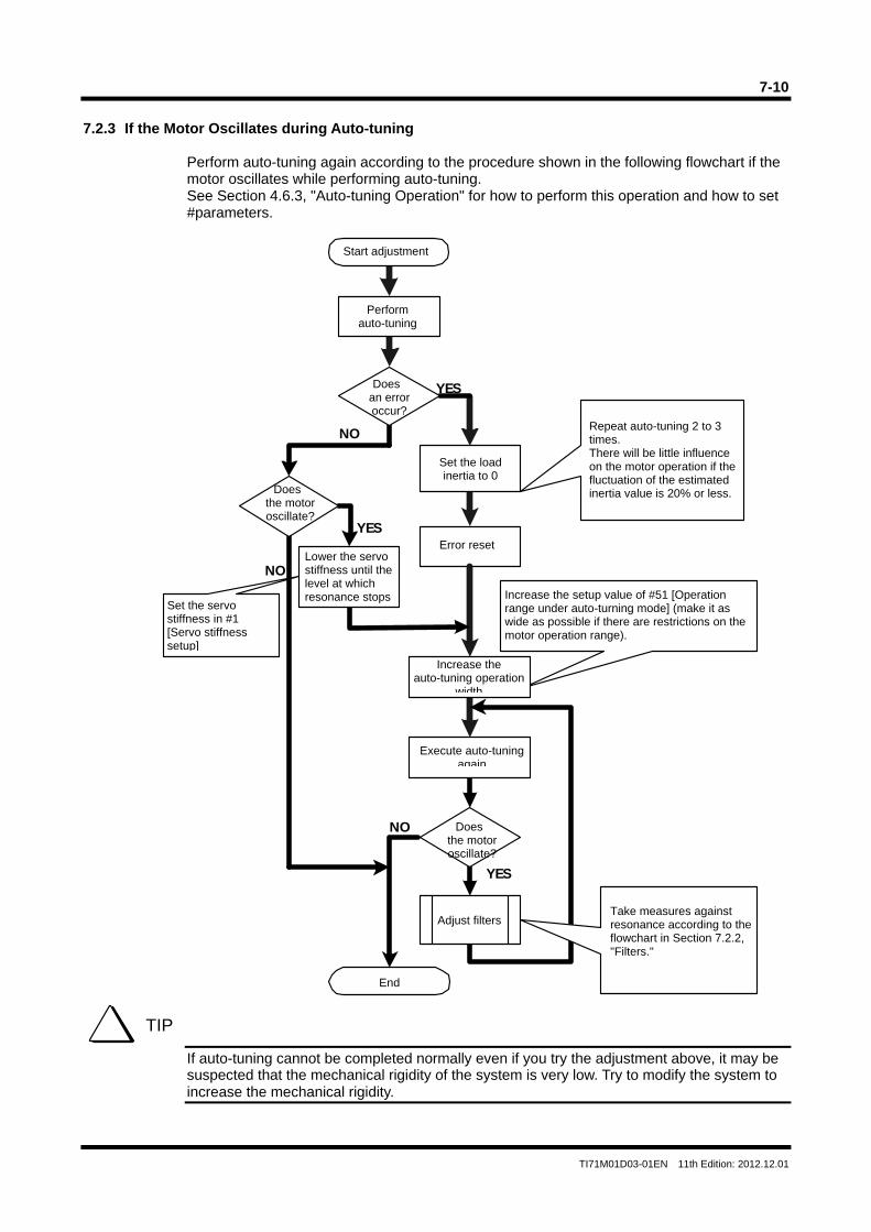
7-10
TI71M01D03-01EN 11th Edition: 2012.12.01
7.2.3 If the Motor Oscillates during Auto-tuning
Perform auto-tuning again according to the procedure shown in the following flowchart if the motor oscillates while performing auto-tuning. See Section 4.6.3, "Auto-tuning Operation" for how to perform this operation and how to set #parameters.
If auto-tuning cannot be completed normally even if you try the adjustment above, it may be suspected that the mechanical rigidity of the system is very low. Try to modify the system to increase the mechanical rigidity.
NO
YES
YES
NO
YES
NO
TIP
Repeat auto-tuning 2 to 3 times. There will be little influence on the motor operation if thefluctuation of the estimated inertia value is 20% or less.
Increase the setup value of #51 [Operation range under auto-turning mode] (make it as wide as possible if there are restrictions on themotor operation range).
Error reset
Increase the auto-tuning operation
width
Execute auto-tuningagain
Does the motor oscillate?
End
Set the servo stiffness in #1 [Servo stiffness setup]
Start adjustment
Perform auto-tuning
Does an error occur?
Set the load inertia to 0
Does the motor oscillate?
Lower the servo stiffness until the level at which resonance stops
Adjust filtersTake measures against resonance according to the flowchart in Section 7.2.2, "Filters."
8-1
TI71M01D03-01EN 11th Edition: 2012.12.01
8. Utility Software
This chapter describes the software used to operate the DrvGIII series (hereafter called the utility software) on a PC.
8.1 Introduction 8.1.1 Operating Conditions
• Hardware Processor: Celeron 300MHz (equivalent) or higher, or Pentium III 500MHz or
higher is recommended. Memory: 64MB minimum Hard disk capacity: 10MB minimum Serial port: 1 port exclusive
• Operating systems
Windows 98 Second Edition, Windows Me, Windows 2000 Professional and Windows XP have been verified as to their compatibility. Windows 2000 Professional or higher is recommended.
• Display
Resolution 800 x 600 or higher, 256 color display minimum • Communication cable
A dedicated cable is required for connection. Either prepare a cable according to the connection diagram shown in the next section, or purchase a manufactured cable.
• Serial port setting
Normally no setting is required as the serial port is controlled on the application side. However, if a special converter or other device is used, set the serial port as follows if necessary.
Communication speed: 38,400 bits/sec Data bits: 8 Parity: None Stop bit: 1 Flow control: None
• Operation verified RS485 card
Manufactured by Interface Co., Ltd. PCI card: PCI-4142PE
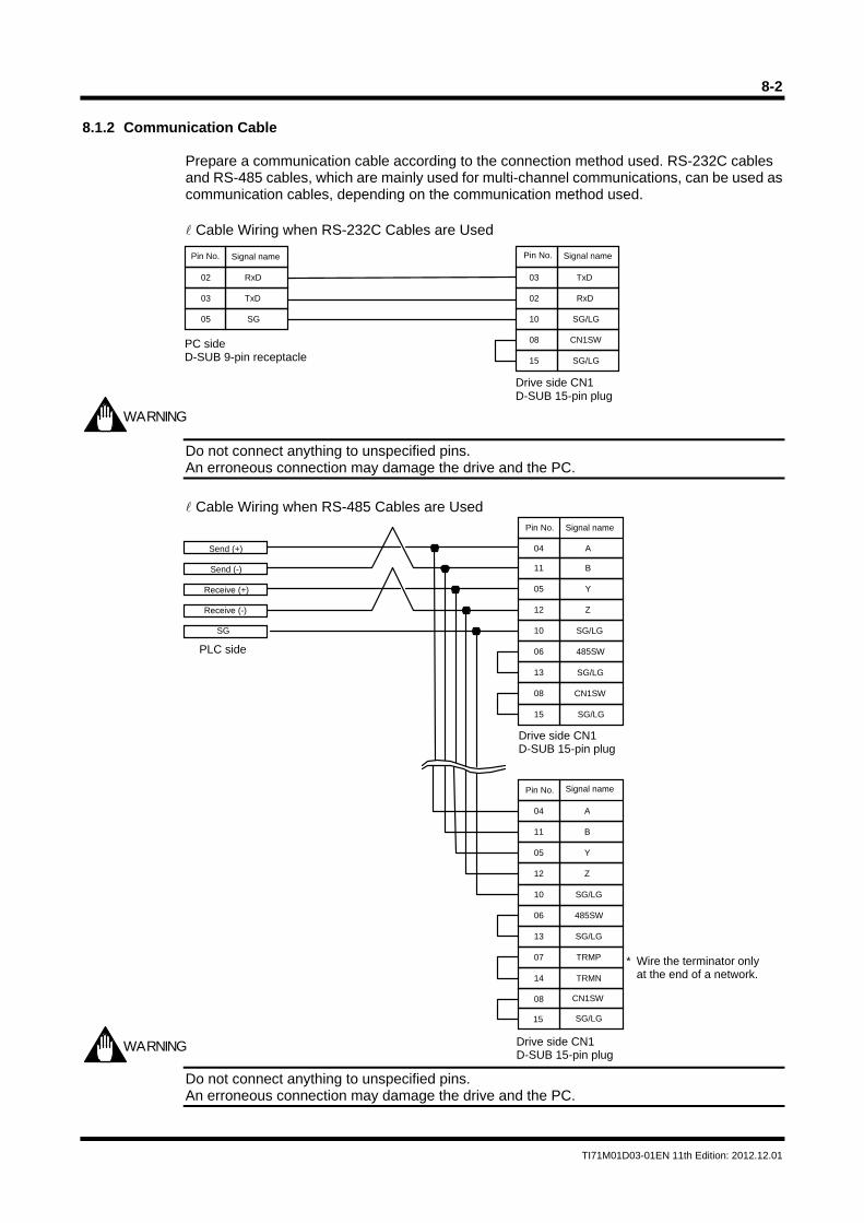
8-2
TI71M01D03-01EN 11th Edition: 2012.12.01
8.1.2 Communication Cable
Prepare a communication cable according to the connection method used. RS-232C cables and RS-485 cables, which are mainly used for multi-channel communications, can be used as communication cables, depending on the communication method used. Cable Wiring when RS-232C Cables are Used
Do not connect anything to unspecified pins. An erroneous connection may damage the drive and the PC.
Cable Wiring when RS-485 Cables are Used
Do not connect anything to unspecified pins. An erroneous connection may damage the drive and the PC.
02
03
05
15
10
02
03
08
Pin No.
SG/LG
Pin No.
RxD
TxD
CN1SW
SG/LG
RxD
TxD
SG
WARNING
WARNING
PC side D-SUB 9-pin receptacle
Signal nameSignal name
Drive side CN1 D-SUB 15-pin plug
Pin No. Signal name
Drive side CN1 D-SUB 15-pin plug
PLC side
Send (+)
Send (-)
Receive (+)
Receive (-)
* Wire the terminator onlyat the end of a network.
Signal name
Drive side CN1 D-SUB 15-pin plug
10
11
12
04
05
A
Y
SG/LG
B
Z
15
08 CN1SW
SG/LG
13
06 485SW
SG/LG
15
08 CN1SW
SG/LG
14
07 TRMP
TRMN
SG
10
11
12
04
05
Pin No.
A
Y
SG/LG
B
Z
13
06 485SW
SG/LG
8-3
TI71M01D03-01EN 11th Edition: 2012.12.01
8.1.3 Installing and Uninstalling
• Installing Start setupj.exe, and follow the instructions given by the installer.
• Uninstalling Be sure to execute from [Control Panel] - [Add or Remove Programs].
Description of Main File Extensions Defined by the Utility Software.
*.prm For saving #parameter settings *.ioc For saving I/O settings *.tbl For saving operation tables *.wha For backing up all user data in the drive in batch mode *.cnd For oscilloscope display setting data and waveform data *.csv For internal settings of the utility software *.pdf For Help
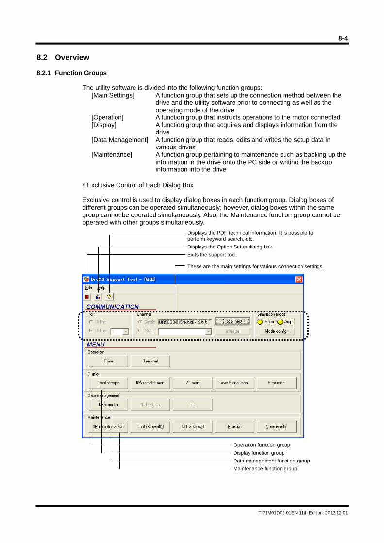
8-4
TI71M01D03-01EN 11th Edition: 2012.12.01
8.2 Overview 8.2.1 Function Groups
The utility software is divided into the following function groups: [Main Settings] A function group that sets up the connection method between the
drive and the utility software prior to connecting as well as the operating mode of the drive
[Operation] A function group that instructs operations to the motor connected [Display] A function group that acquires and displays information from the
drive [Data Management] A function group that reads, edits and writes the setup data in
various drives [Maintenance] A function group pertaining to maintenance such as backing up the
information in the drive onto the PC side or writing the backup information into the drive
Exclusive Control of Each Dialog Box Exclusive control is used to display dialog boxes in each function group. Dialog boxes of different groups can be operated simultaneously; however, dialog boxes within the same group cannot be operated simultaneously. Also, the Maintenance function group cannot be operated with other groups simultaneously.
Displays the PDF technical information. It is possible to perform keyword search, etc.
Displays the Option Setup dialog box.
Exits the support tool. These are the main settings for various connection settings.
Operation function group
Display function group
Data management function group
Maintenance function group
8-5
TI71M01D03-01EN 11th Edition: 2012.12.01
8.2.2 Function List Main Settings
Language Selection It is possible to switch between Japanese and English. The language switching takes place after [Disconnect] is selected once. Online/Offline Selection Select [Online] to actually connect to the drive, and select [Offline] to browse or edit the drive data without connecting to the drive. When offline, operations such as creating table data, browsing waveform data using the oscilloscope function, and browsing backup data can be performed. Connection Port Selection Select the COM port number of the PC used. Single/Multichannel Selection If two or more drives are connected via RS485, select the drive station number to be connected after selecting multichannel connection. Only one drive can be connected at a time during multichannel communication using the utility software. Operating Mode Setting (motorless operation/powerless operation setting) This setting is used when the drive's built-in emulation function is used to check the motor operation while the motor is not actually connected. Host Communication Cycle Setting This sets a basic cycle when connecting the drive and a PC in series. Communication may be stabilized by setting this to a larger value if the communication load on the PC side is heavy. Normally set this to 10ms.
Operation Group
Drive The operation group function issues operating commands to the drive. Terminal The operation group function references and changes command inputs and parameters in text format.
Display Group
Oscilloscope This group function displays the drive status as if operating an actual oscilloscope. #parameter monitor This group function displays the specified #parameter values continuously. I/O monitor This group function displays the hard I/O status continuously. Axis Signal monitor This group function displays the information pertaining to axis operation continuously. Error monitor This group function acquires the current error information of the drive and past error history continuously.
8-6
TI71M01D03-01EN 11th Edition: 2012.12.01
Data Management Group
#Parameter This group function sets up the required main parameters for the drive. The parameters are classified by purpose. Table data This group function creates and changes operation table data. I/O This group function assigns hard I/O, performs logical settings, and the initial value settings of logic I/O.
Maintenance Group
Parameter viewer This group function backs up the #parameters that are currently being set in the drive, and performs restore operation using the files saved. Table viewer This group function backs up the table data that is currently being set in the drive, and performs restore operation using the file saved. I/O viewer This group function backs up the I/O that is currently being set in the drive, and performs restore operation using the file saved. Backup This group function backs up all user data (data whose settings can be changed by users) that is currently being set in the drive, and performs batch restore operation using the file saved. Version information The connected drive information, contact information and other information are displayed.
Help Display This displays Help in Adobe Acrobat PDF. It is possible to perform keyword search, etc.

8-7
TI71M01D03-01EN 11th Edition: 2012.12.01
8.3 Required Settings Prior to Connecting
Perform the basic settings of the utility software according to the actual operating environment before connecting to the drive. The previous settings are used when the utility software is started again from the second time on, so there is no need for setting up the utility software again.
8.3.1 Connecting and Reconnecting
The status where the utility software and corresponding drive are connected via host communication is called [Connected state]. The communication status between the utility software and the drive is always monitored in order to improve reliability. Therefore, to use this utility software, start with [Connect] and end with [Disconnect] after completing an operation. [Disconnect] is automatically executed when the utility software is closed, so it is not necessary to select it. If the power is cycled after the power to the drive side is disconnected when using the utility software, or if the communication cable is disconnected, [Connect] is disconnected. In this case, it is necessary to execute [Connect] again. However, the connection may be recovered simply by pressing the [Initialize Communication] button. In such a case, please note that the utility software runs as if the drive prior to the disconnection is being connected, because the drive information is not acquired again.
8.3.2 Communication Settings Connection Port Selection
By choosing [Communication Port] - [Online], select the number of the serial port to be actually connected to the drive among the serial ports installed to the PC. At this time, if the specified port is found on the PC and the correct drive is connected to that port, a motor model code is displayed, notifying the connection valid status.
Connection Format Selection Single Channel Connection This is a basic connection method. A dedicated cable is used to perform communication by connecting one serial port to one drive. Select [Single] from [Connection Method] in option settings, and execute [Connect]. Multichannel Connection The multichannel connection function is used to connect one serial port to multiple drives connected in a multidrop RS485 communication. Select [Multi] from [Connection Method] in option settings, and execute [Connect]. The utility software acquires the information of all drives currently being connected. The result is displayed in a pull-down box, so execute [Connect] after selecting a desired drive ID. Be aware that the utility software and the drive are always performing one to one communication even when two or more drives are connected. If it is necessary to communicate with a drive of other station, execute [Disconnect] once, and then change the drive ID and reconnect. Offline Connection Parts of the utility software function can be used without connecting a port to the drive by selecting [Offline] in communication port settings. Part of the maintenance function and oscilloscope function can be used offline. Files pertaining to existing drives can be browsed.
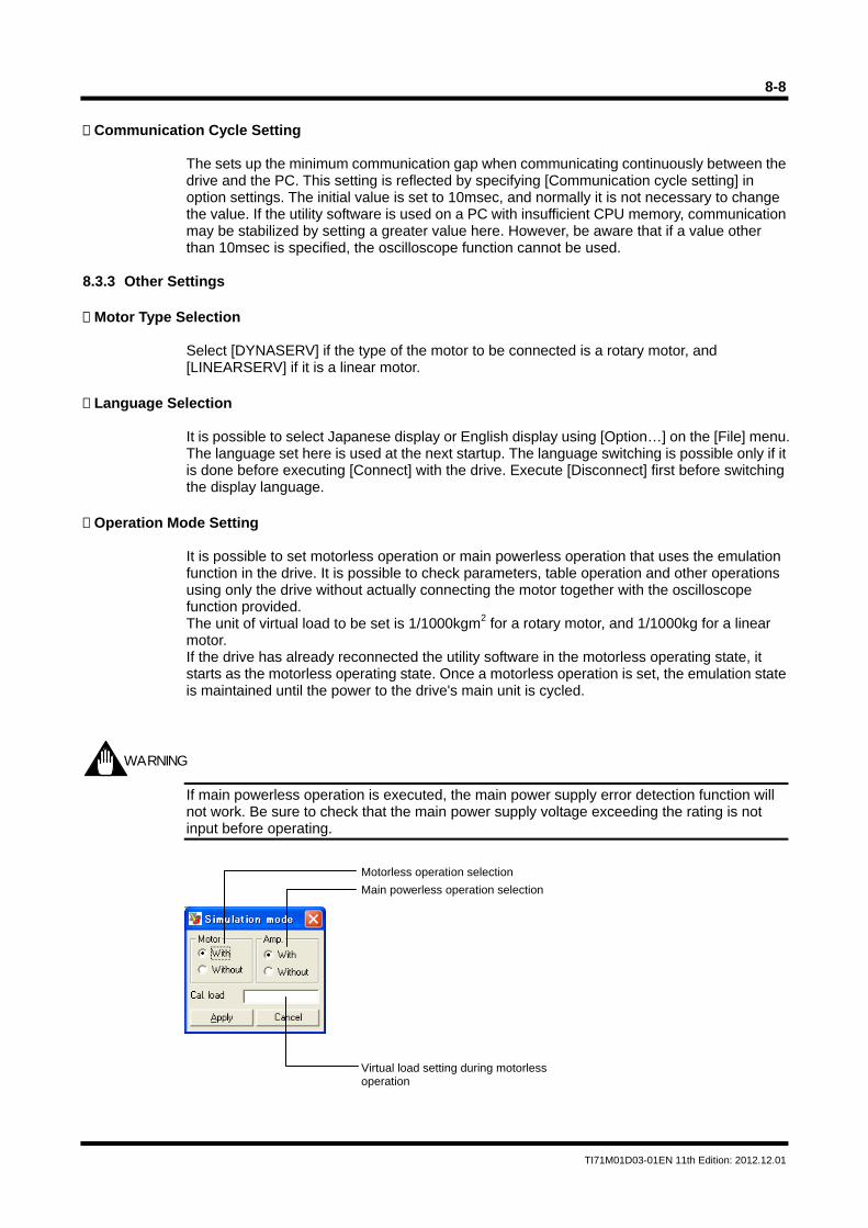
8-8
TI71M01D03-01EN 11th Edition: 2012.12.01
Communication Cycle Setting
The sets up the minimum communication gap when communicating continuously between the drive and the PC. This setting is reflected by specifying [Communication cycle setting] in option settings. The initial value is set to 10msec, and normally it is not necessary to change the value. If the utility software is used on a PC with insufficient CPU memory, communication may be stabilized by setting a greater value here. However, be aware that if a value other than 10msec is specified, the oscilloscope function cannot be used.
8.3.3 Other Settings Motor Type Selection
Select [DYNASERV] if the type of the motor to be connected is a rotary motor, and [LINEARSERV] if it is a linear motor.
Language Selection
It is possible to select Japanese display or English display using [Option…] on the [File] menu. The language set here is used at the next startup. The language switching is possible only if it is done before executing [Connect] with the drive. Execute [Disconnect] first before switching the display language.
Operation Mode Setting
It is possible to set motorless operation or main powerless operation that uses the emulation function in the drive. It is possible to check parameters, table operation and other operations using only the drive without actually connecting the motor together with the oscilloscope function provided. The unit of virtual load to be set is 1/1000kgm2 for a rotary motor, and 1/1000kg for a linear motor. If the drive has already reconnected the utility software in the motorless operating state, it starts as the motorless operating state. Once a motorless operation is set, the emulation state is maintained until the power to the drive's main unit is cycled.
If main powerless operation is executed, the main power supply error detection function will not work. Be sure to check that the main power supply voltage exceeding the rating is not input before operating.
WARNING
Motorless operation selection
Main powerless operation selection
Virtual load setting during motorless operation
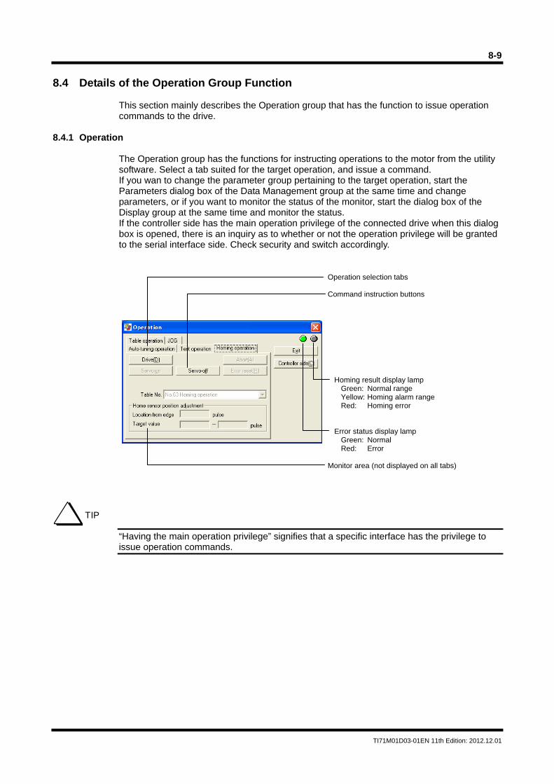
8-9
TI71M01D03-01EN 11th Edition: 2012.12.01
8.4 Details of the Operation Group Function
This section mainly describes the Operation group that has the function to issue operation commands to the drive.
8.4.1 Operation
The Operation group has the functions for instructing operations to the motor from the utility software. Select a tab suited for the target operation, and issue a command. If you wan to change the parameter group pertaining to the target operation, start the Parameters dialog box of the Data Management group at the same time and change parameters, or if you want to monitor the status of the monitor, start the dialog box of the Display group at the same time and monitor the status. If the controller side has the main operation privilege of the connected drive when this dialog box is opened, there is an inquiry as to whether or not the operation privilege will be granted to the serial interface side. Check security and switch accordingly.
“Having the main operation privilege” signifies that a specific interface has the privilege to issue operation commands.
Operation selection tabs Command instruction buttons
Homing result display lamp Green: Normal range Yellow: Homing alarm range Red: Homing error
Error status display lamp
Green: Normal Red: Error
Monitor area (not displayed on all tabs)
TIP
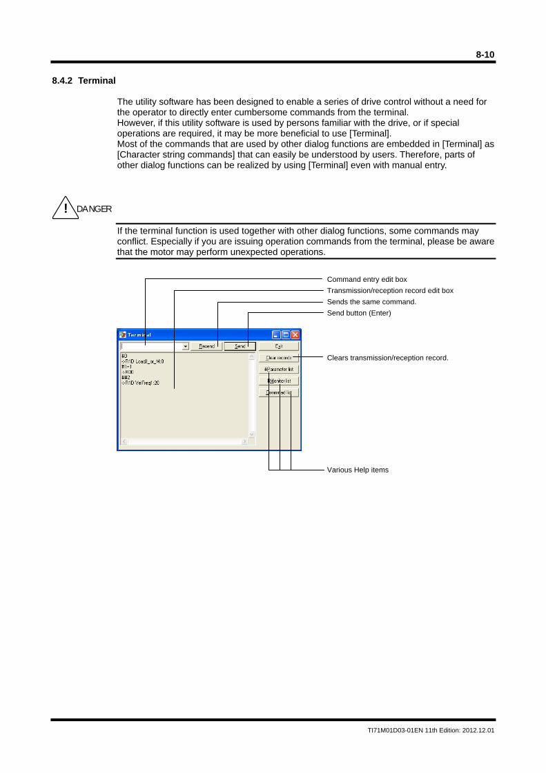
8-10
TI71M01D03-01EN 11th Edition: 2012.12.01
8.4.2 Terminal
The utility software has been designed to enable a series of drive control without a need for the operator to directly enter cumbersome commands from the terminal. However, if this utility software is used by persons familiar with the drive, or if special operations are required, it may be more beneficial to use [Terminal]. Most of the commands that are used by other dialog functions are embedded in [Terminal] as [Character string commands] that can easily be understood by users. Therefore, parts of other dialog functions can be realized by using [Terminal] even with manual entry.
If the terminal function is used together with other dialog functions, some commands may conflict. Especially if you are issuing operation commands from the terminal, please be aware that the motor may perform unexpected operations.
! DANGER
Command entry edit box
Transmission/reception record edit box
Sends the same command.
Send button (Enter)
Clears transmission/reception record.
Various Help items
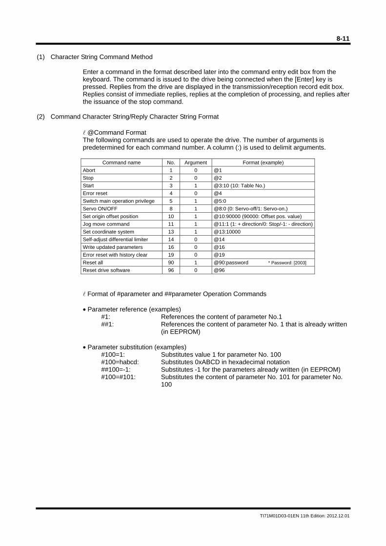
8-11
TI71M01D03-01EN 11th Edition: 2012.12.01
(1) Character String Command Method
Enter a command in the format described later into the command entry edit box from the keyboard. The command is issued to the drive being connected when the [Enter] key is pressed. Replies from the drive are displayed in the transmission/reception record edit box. Replies consist of immediate replies, replies at the completion of processing, and replies after the issuance of the stop command.
(2) Command Character String/Reply Character String Format
@Command Format The following commands are used to operate the drive. The number of arguments is predetermined for each command number. A column (:) is used to delimit arguments.
Command name No. Argument Format (example)
Abort 1 0 @1
Stop 2 0 @2
Start 3 1 @3:10 (10: Table No.)
Error reset 4 0 @4
Switch main operation privilege 5 1 @5:0
Servo ON/OFF 8 1 @8:0 (0: Servo-off/1: Servo-on.)
Set origin offset position 10 1 @10:90000 (90000: Offset pos. value)
Jog move command 11 1 @11:1 (1: + direction/0: Stop/-1: - direction)
Set coordinate system 13 1 @13:10000
Self-adjust differential limiter 14 0 @14
Write updated parameters 16 0 @16
Error reset with history clear 19 0 @19
Reset all 90 1 @90:password * Password: [2003]
Reset drive software 96 0 @96
Format of #parameter and ##parameter Operation Commands • Parameter reference (examples)
#1: References the content of parameter No.1 ##1: References the content of parameter No. 1 that is already written
(in EEPROM) • Parameter substitution (examples)
#100=1: Substitutes value 1 for parameter No. 100 #100=habcd: Substitutes 0xABCD in hexadecimal notation ##100=-1: Substitutes -1 for the parameters already written (in EEPROM) #100=#101: Substitutes the content of parameter No. 101 for parameter No.
100
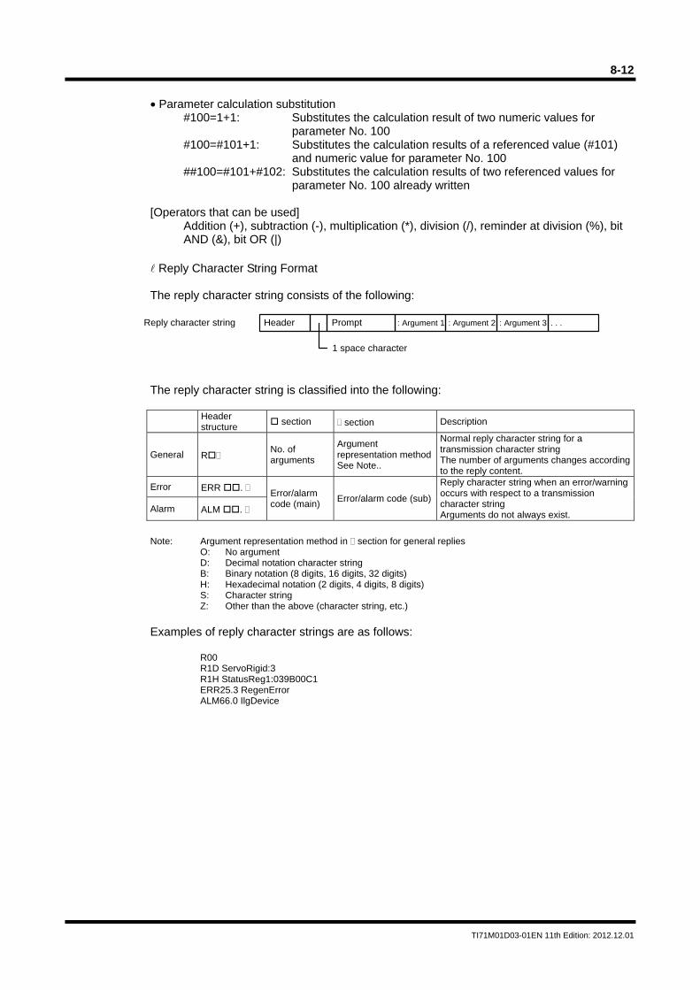
8-12
TI71M01D03-01EN 11th Edition: 2012.12.01
• Parameter calculation substitution
#100=1+1: Substitutes the calculation result of two numeric values for parameter No. 100
#100=#101+1: Substitutes the calculation results of a referenced value (#101) and numeric value for parameter No. 100
##100=#101+#102: Substitutes the calculation results of two referenced values for parameter No. 100 already written
[Operators that can be used]
Addition (+), subtraction (-), multiplication (*), division (/), reminder at division (%), bit AND (&), bit OR (|)
Reply Character String Format The reply character string consists of the following:
The reply character string is classified into the following:
Header structure
section section Description
General R No. of arguments
Argument representation methodSee Note..
Normal reply character string for a transmission character string The number of arguments changes according to the reply content.
Error ERR . Error/alarm code (main)
Error/alarm code (sub)
Reply character string when an error/warning occurs with respect to a transmission character string Arguments do not always exist.
Alarm ALM .
Note: Argument representation method in section for general replies
O: No argument D: Decimal notation character string B: Binary notation (8 digits, 16 digits, 32 digits) H: Hexadecimal notation (2 digits, 4 digits, 8 digits) S: Character string Z: Other than the above (character string, etc.)
Examples of reply character strings are as follows:
R00 R1D ServoRigid:3 R1H StatusReg1:039B00C1 ERR25.3 RegenError ALM66.0 IlgDevice
Reply character string Header Prompt : Argument 1 : Argument 2 : Argument 3 . . .
1 space character
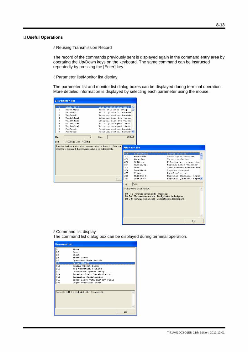
8-13
TI71M01D03-01EN 11th Edition: 2012.12.01
Useful Operations
Reusing Transmission Record The record of the commands previously sent is displayed again in the command entry area by operating the Up/Down keys on the keyboard. The same command can be instructed repeatedly by pressing the [Enter] key. Parameter list/Monitor list display The parameter list and monitor list dialog boxes can be displayed during terminal operation. More detailed information is displayed by selecting each parameter using the mouse. Command list display The command list dialog box can be displayed during terminal operation.
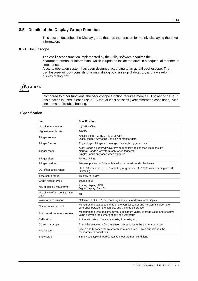
8-14
TI71M01D03-01EN 11th Edition: 2012.12.01
8.5 Details of the Display Group Function
This section describes the Display group that has the function for mainly displaying the drive information.
8.5.1 Oscilloscope
The oscilloscope function implemented by the utility software acquires the #parameter/#monitor information, which is updated inside the drive in a sequential manner, in time series. Also, its operation system has been designed according to an actual oscilloscope. The oscilloscope window consists of a main dialog box, a setup dialog box, and a waveform display dialog box.
Compared to other functions, the oscilloscope function requires more CPU power of a PC. If this function is used, please use a PC that at least satisfies [Recommended conditions]. Also, see items in “Troubleshooting.”
Specification
Item Specification
No. of input channels 4 (CH1 ~ CH4)
Highest sample rate 10kS/s
Trigger source Analog trigger: CH1, CH2, CH3, CH4 Digital trigger: Any of bit 0 to bit 7 of monitor data
Trigger function Edge trigger: Trigger at the edge of a single trigger source
Trigger mode Auto: Loads a buffered waveform sequentially at less than 100msec/div Normal: Loads a waveform only when triggered Single: Loads only once when triggered
Trigger slope Rising, falling
Trigger position 10-point position of 0div to 9div within a waveform display frame
DC offset setup range Up to 10 times the ±UNIT/div setting (e.g., range of ±10000 with a setting of 1000 UNIT/div)
Time setup range 1ms/div to 5s/div
Graph refresh cycle 100ms to 1s
No. of display waveforms Analog display: 4CH Digital display: 8 x 4CH
No. of waveform configuration data
100
Waveform calculation Calculation of +, -, *, and / among channels, and waveform display
Cursor measurement Measures the values and time of the vertical cursor and horizontal cursor, the difference between the cursors, and the time difference
Auto waveform measurement Measures the time, maximum value, minimum value, average value and effective value between the cursors of any one waveform
Calibration Automatic sets up the vertical axis, time axis, etc.
Screen hardcopy Prints the Waveform Display dialog box window to the printer connected
File function Saves and browses the waveform data measured. Saves and reloads the measurement conditions.
Easy setup Simply sets typical representative measurement conditions
CAUTION
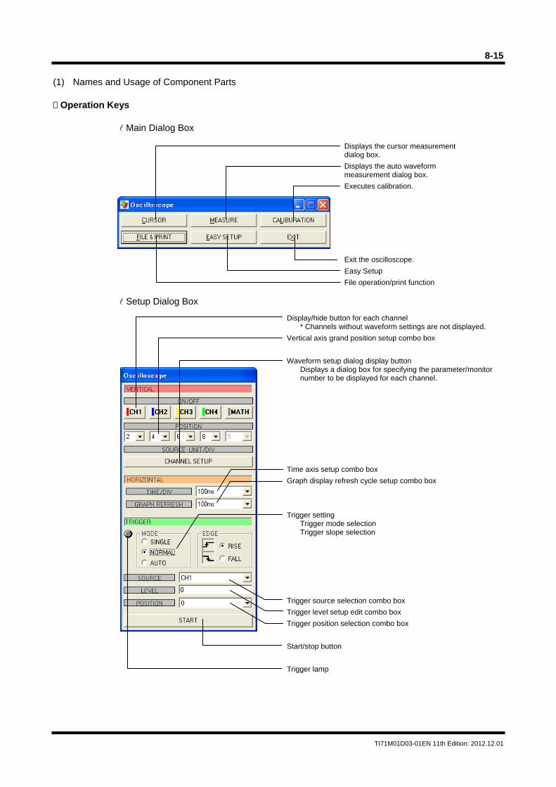
8-15
TI71M01D03-01EN 11th Edition: 2012.12.01
(1) Names and Usage of Component Parts Operation Keys
Main Dialog Box
Setup Dialog Box
Displays the cursor measurement dialog box.
Displays the auto waveform measurement dialog box.
Executes calibration.
Exit the oscilloscope.
Easy Setup
File operation/print function
Display/hide button for each channel * Channels without waveform settings are not displayed.
Vertical axis grand position setup combo box
Waveform setup dialog display button Displays a dialog box for specifying the parameter/monitor number to be displayed for each channel.
Time axis setup combo box
Graph display refresh cycle setup combo box
Trigger setting Trigger mode selection Trigger slope selection
Trigger source selection combo box
Trigger level setup edit combo box
Trigger position selection combo box
Start/stop button
Trigger lamp
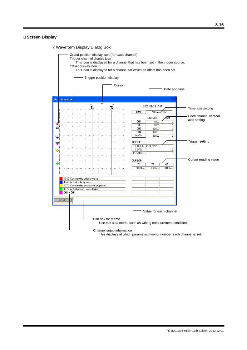
8-16
TI71M01D03-01EN 11th Edition: 2012.12.01
Screen Display
Waveform Display Dialog Box
Grand position display icon (for each channel) Trigger channel display icon
This icon is displayed for a channel that has been set in the trigger source. Offset display icon
This icon is displayed for a channel for which an offset has been set.
Trigger position display
Cursor Date and time
Time axis setting Each channel vertical axis setting Trigger setting Cursor reading value
Value for each channel Edit box for memo
Use this as a memo such as writing measurement conditions. Channel setup information
This displays at which parameter/monitor number each channel is set.
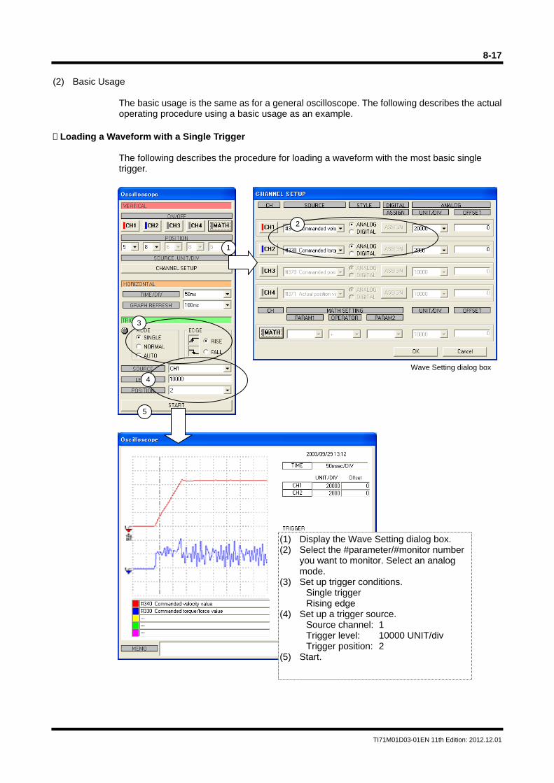
8-17
TI71M01D03-01EN 11th Edition: 2012.12.01
(2) Basic Usage
The basic usage is the same as for a general oscilloscope. The following describes the actual operating procedure using a basic usage as an example.
Loading a Waveform with a Single Trigger
The following describes the procedure for loading a waveform with the most basic single trigger.
1
2
3
4
5
Wave Setting dialog box
(1) Display the Wave Setting dialog box. (2) Select the #parameter/#monitor number
you want to monitor. Select an analog mode.
(3) Set up trigger conditions. Single trigger Rising edge
(4) Set up a trigger source. Source channel: 1 Trigger level: 10000 UNIT/div Trigger position: 2
(5) Start.
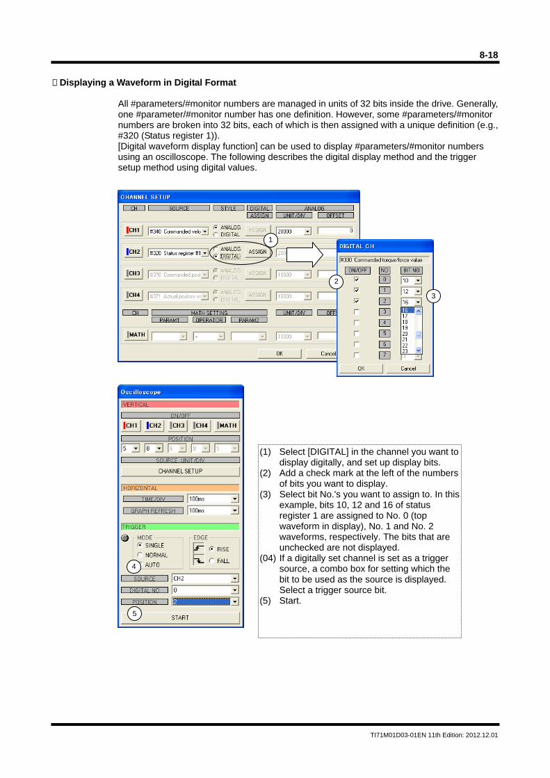
8-18
TI71M01D03-01EN 11th Edition: 2012.12.01
Displaying a Waveform in Digital Format
All #parameters/#monitor numbers are managed in units of 32 bits inside the drive. Generally, one #parameter/#monitor number has one definition. However, some #parameters/#monitor numbers are broken into 32 bits, each of which is then assigned with a unique definition (e.g., #320 (Status register 1)). [Digital waveform display function] can be used to display #parameters/#monitor numbers using an oscilloscope. The following describes the digital display method and the trigger setup method using digital values.
1
2
3
4
5
(1) Select [DIGITAL] in the channel you want to display digitally, and set up display bits.
(2) Add a check mark at the left of the numbers of bits you want to display.
(3) Select bit No.'s you want to assign to. In this example, bits 10, 12 and 16 of status register 1 are assigned to No. 0 (top waveform in display), No. 1 and No. 2 waveforms, respectively. The bits that are unchecked are not displayed.
(04) If a digitally set channel is set as a trigger source, a combo box for setting which the bit to be used as the source is displayed. Select a trigger source bit.
(5) Start.

8-19
TI71M01D03-01EN 11th Edition: 2012.12.01
A maximum of eight bits can be displayed per channel. To monitor more than eight bits at the same time, a maximum of 32 bits can be displayed by assigning multi-channels to digital display.
(6) A trigger is applied at the rise of the bit set in No. 0. In this example, a trigger is applied at the rise of the axis-in-operation signal, #320 bit 10.
(7) The status of each bit is expressed by 1: H and 0: L while in digital display.
TIP
6
7
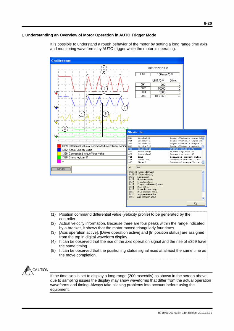
8-20
TI71M01D03-01EN 11th Edition: 2012.12.01
Understanding an Overview of Motor Operation in AUTO Trigger Mode
It is possible to understand a rough behavior of the motor by setting a long range time axis and monitoring waveforms by AUTO trigger while the motor is operating.
If the time axis is set to display a long range (200 msec/div) as shown in the screen above, due to sampling issues the display may show waveforms that differ from the actual operation waveforms and timing. Always take aliasing problems into account before using the equipment.
(1) Position command differential value (velocity profile) to be generated by the controller
(2) Actual velocity information. Because there are four peaks within the range indicated by a bracket, it shows that the motor moved triangularly four times.
(3) [Axis operation active], [Drive operation active] and [In position status] are assigned from the top in digital waveform display.
(4) It can be observed that the rise of the axis operation signal and the rise of #359 have the same timing.
(5) It can be observed that the positioning status signal rises at almost the same time as the move completion.
CAUTION
3
7
1
2
4 5
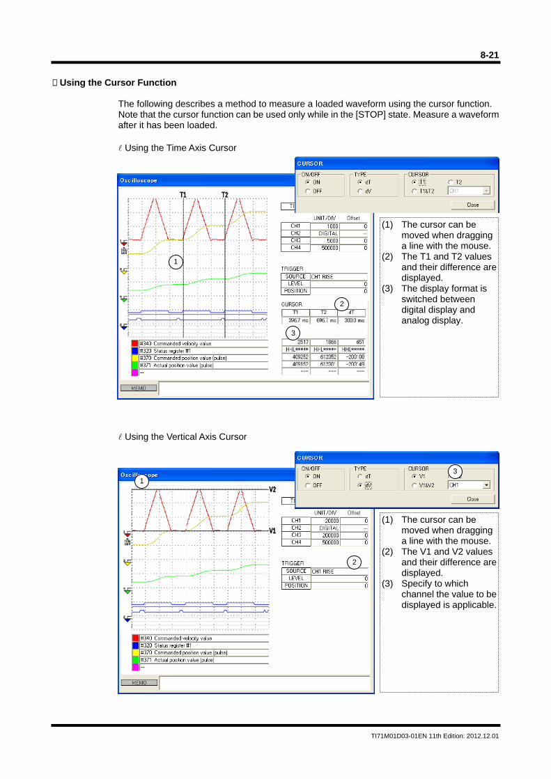
8-21
TI71M01D03-01EN 11th Edition: 2012.12.01
Using the Cursor Function
The following describes a method to measure a loaded waveform using the cursor function. Note that the cursor function can be used only while in the [STOP] state. Measure a waveform after it has been loaded. Using the Time Axis Cursor
Using the Vertical Axis Cursor
(1) The cursor can be moved when dragging a line with the mouse.
(2) The T1 and T2 values and their difference are displayed.
(3) The display format is switched between digital display and analog display.
3
1
2
(1) The cursor can be moved when dragging a line with the mouse.
(2) The V1 and V2 values and their difference are displayed.
(3) Specify to which channel the value to be displayed is applicable.
31
2
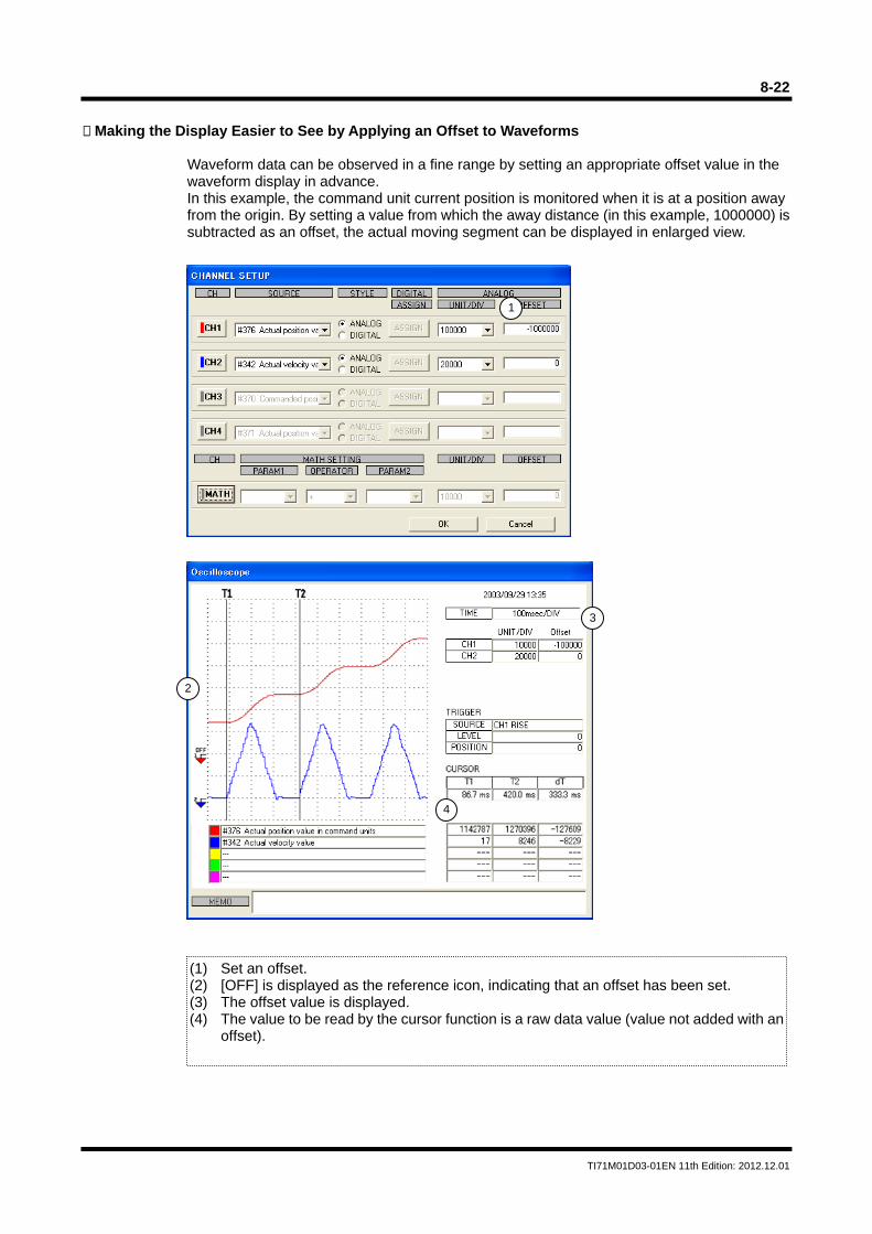
8-22
TI71M01D03-01EN 11th Edition: 2012.12.01
Making the Display Easier to See by Applying an Offset to Waveforms
Waveform data can be observed in a fine range by setting an appropriate offset value in the waveform display in advance. In this example, the command unit current position is monitored when it is at a position away from the origin. By setting a value from which the away distance (in this example, 1000000) is subtracted as an offset, the actual moving segment can be displayed in enlarged view.
(1) Set an offset. (2) [OFF] is displayed as the reference icon, indicating that an offset has been set. (3) The offset value is displayed. (4) The value to be read by the cursor function is a raw data value (value not added with an
offset).
3
1
2
4
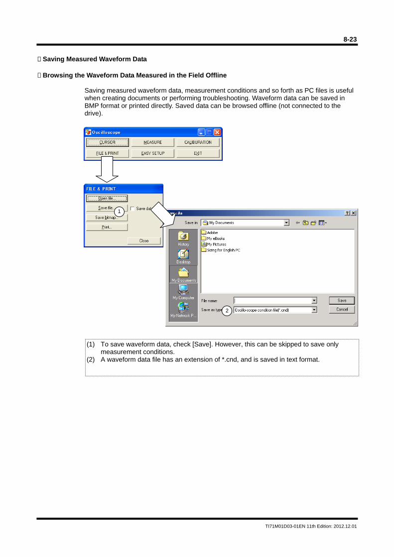
8-23
TI71M01D03-01EN 11th Edition: 2012.12.01
Saving Measured Waveform Data Browsing the Waveform Data Measured in the Field Offline
Saving measured waveform data, measurement conditions and so forth as PC files is useful when creating documents or performing troubleshooting. Waveform data can be saved in BMP format or printed directly. Saved data can be browsed offline (not connected to the drive).
1
2
(1) To save waveform data, check [Save]. However, this can be skipped to save only measurement conditions.
(2) A waveform data file has an extension of *.cnd, and is saved in text format.
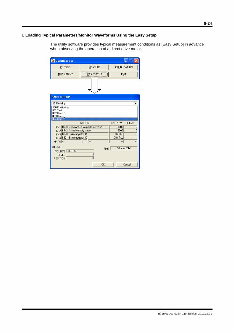
8-24
TI71M01D03-01EN 11th Edition: 2012.12.01
Loading Typical Parameters/Monitor Waveforms Using the Easy Setup
The utility software provides typical measurement conditions as [Easy Setup] in advance when observing the operation of a direct drive motor.
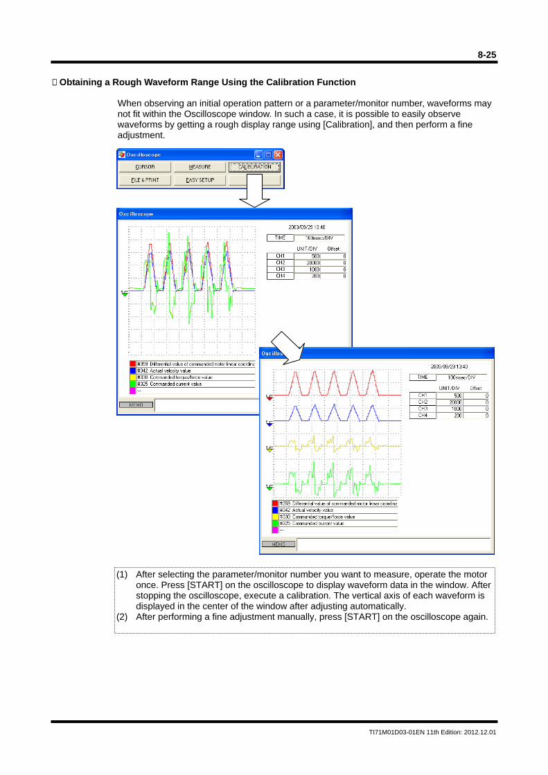
8-25
TI71M01D03-01EN 11th Edition: 2012.12.01
Obtaining a Rough Waveform Range Using the Calibration Function
When observing an initial operation pattern or a parameter/monitor number, waveforms may not fit within the Oscilloscope window. In such a case, it is possible to easily observe waveforms by getting a rough display range using [Calibration], and then perform a fine adjustment.
(1) After selecting the parameter/monitor number you want to measure, operate the motor once. Press [START] on the oscilloscope to display waveform data in the window. After stopping the oscilloscope, execute a calibration. The vertical axis of each waveform is displayed in the center of the window after adjusting automatically.
(2) After performing a fine adjustment manually, press [START] on the oscilloscope again.
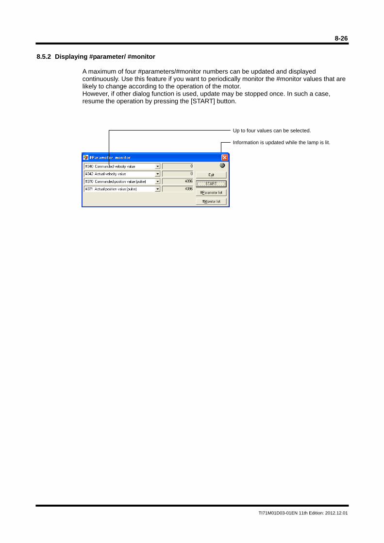
8-26
TI71M01D03-01EN 11th Edition: 2012.12.01
8.5.2 Displaying #parameter/ #monitor
A maximum of four #parameters/#monitor numbers can be updated and displayed continuously. Use this feature if you want to periodically monitor the #monitor values that are likely to change according to the operation of the motor. However, if other dialog function is used, update may be stopped once. In such a case, resume the operation by pressing the [START] button.
Up to four values can be selected. Information is updated while the lamp is lit.
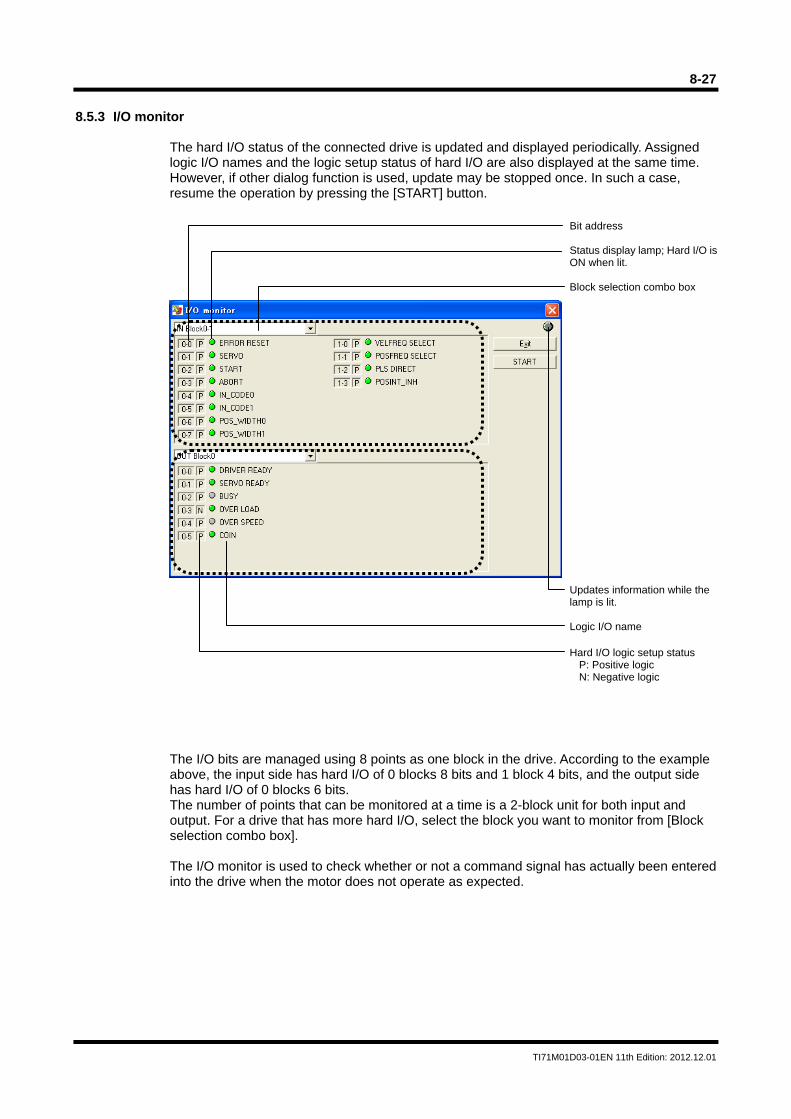
8-27
TI71M01D03-01EN 11th Edition: 2012.12.01
8.5.3 I/O monitor
The hard I/O status of the connected drive is updated and displayed periodically. Assigned logic I/O names and the logic setup status of hard I/O are also displayed at the same time. However, if other dialog function is used, update may be stopped once. In such a case, resume the operation by pressing the [START] button.
The I/O bits are managed using 8 points as one block in the drive. According to the example above, the input side has hard I/O of 0 blocks 8 bits and 1 block 4 bits, and the output side has hard I/O of 0 blocks 6 bits. The number of points that can be monitored at a time is a 2-block unit for both input and output. For a drive that has more hard I/O, select the block you want to monitor from [Block selection combo box]. The I/O monitor is used to check whether or not a command signal has actually been entered into the drive when the motor does not operate as expected.
Bit address Status display lamp; Hard I/O isON when lit. Block selection combo box Updates information while the lamp is lit. Logic I/O name Hard I/O logic setup status
P: Positive logic N: Negative logic
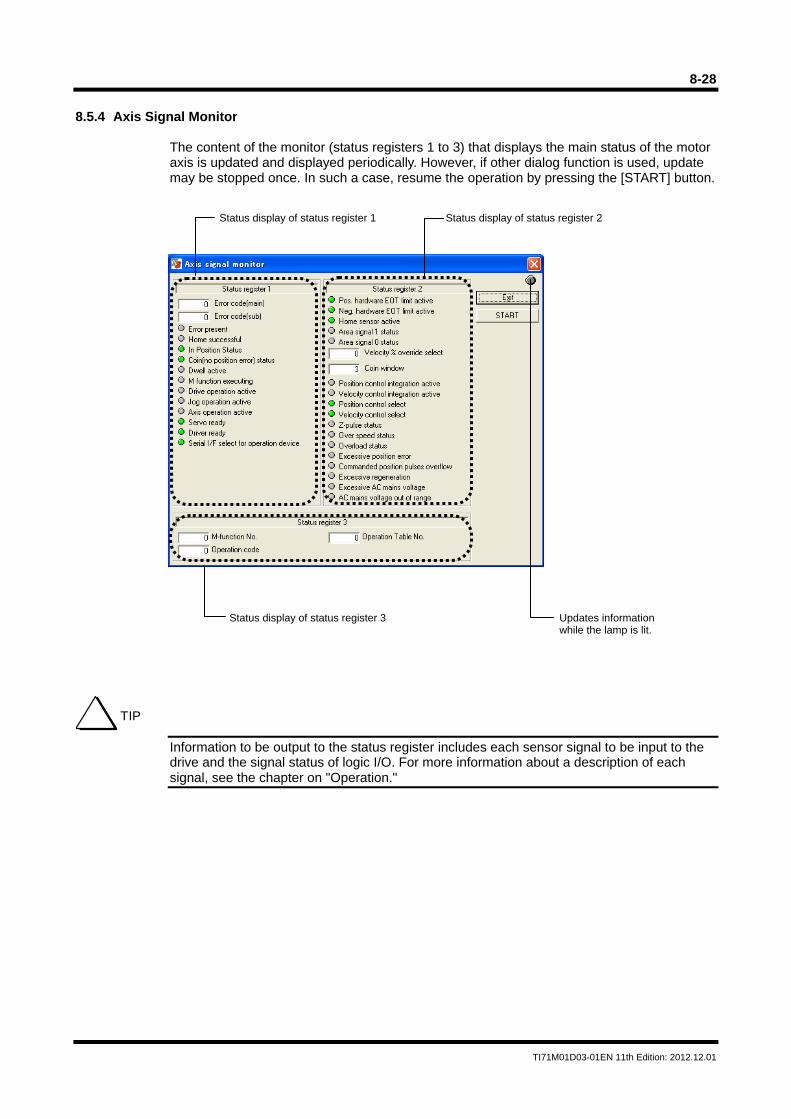
8-28
TI71M01D03-01EN 11th Edition: 2012.12.01
8.5.4 Axis Signal Monitor
The content of the monitor (status registers 1 to 3) that displays the main status of the motor axis is updated and displayed periodically. However, if other dialog function is used, update may be stopped once. In such a case, resume the operation by pressing the [START] button.
Information to be output to the status register includes each sensor signal to be input to the drive and the signal status of logic I/O. For more information about a description of each signal, see the chapter on "Operation."
Status display of status register 1 Status display of status register 2
Status display of status register 3 Updates information while the lamp is lit.
TIP
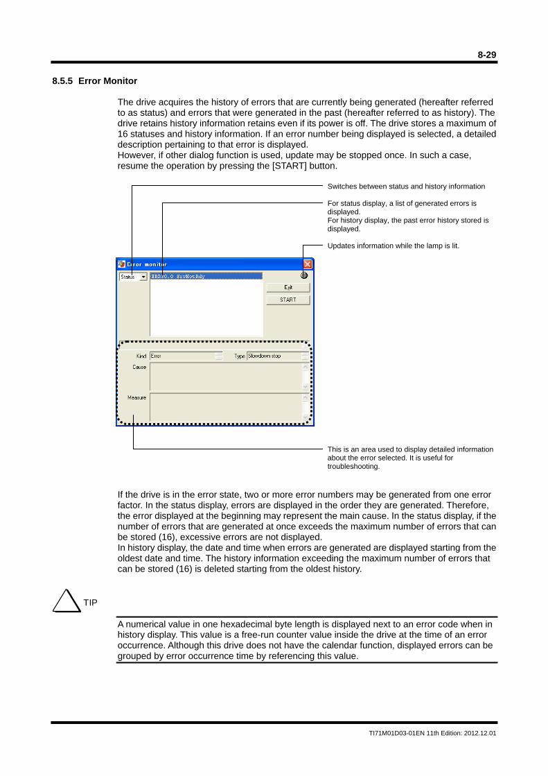
8-29
TI71M01D03-01EN 11th Edition: 2012.12.01
8.5.5 Error Monitor
The drive acquires the history of errors that are currently being generated (hereafter referred to as status) and errors that were generated in the past (hereafter referred to as history). The drive retains history information retains even if its power is off. The drive stores a maximum of 16 statuses and history information. If an error number being displayed is selected, a detailed description pertaining to that error is displayed. However, if other dialog function is used, update may be stopped once. In such a case, resume the operation by pressing the [START] button.
If the drive is in the error state, two or more error numbers may be generated from one error factor. In the status display, errors are displayed in the order they are generated. Therefore, the error displayed at the beginning may represent the main cause. In the status display, if the number of errors that are generated at once exceeds the maximum number of errors that can be stored (16), excessive errors are not displayed. In history display, the date and time when errors are generated are displayed starting from the oldest date and time. The history information exceeding the maximum number of errors that can be stored (16) is deleted starting from the oldest history.
A numerical value in one hexadecimal byte length is displayed next to an error code when in history display. This value is a free-run counter value inside the drive at the time of an error occurrence. Although this drive does not have the calendar function, displayed errors can be grouped by error occurrence time by referencing this value.
Switches between status and history information For status display, a list of generated errors is displayed. For history display, the past error history stored is displayed. Updates information while the lamp is lit. This is an area used to display detailed information about the error selected. It is useful for troubleshooting.
TIP
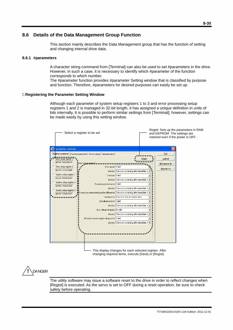
8-30
TI71M01D03-01EN 11th Edition: 2012.12.01
8.6 Details of the Data Management Group Function
This section mainly describes the Data Management group that has the function of setting and changing internal drive data.
8.6.1 #parameters
A character string command from [Terminal] can also be used to set #parameters in the drive. However, in such a case, it is necessary to identify which #parameter of the function corresponds to which number. The #parameter function provides #parameter Setting window that is classified by purpose and function. Therefore, #parameters for desired purposes can easily be set up.
Registering the Parameter Setting Window
Although each parameter of system setup registers 1 to 3 and error processing setup registers 1 and 2 is managed in 32-bit length, it has assigned a unique definition in units of bits internally. It is possible to perform similar settings from [Terminal]; however, settings can be made easily by using this setting window.
The utility software may issue a software reset to the drive in order to reflect changes when [Regist] is executed. As the servo is set to OFF during a reset operation, be sure to check safety before operating.
Select a register to be setRegist: Sets up the parameters in RAMand EEPROM. The settings are retained even if the power is OFF.
This display changes for each selected register. After changing required items, execute [Save] or [Regist].
! DANGER
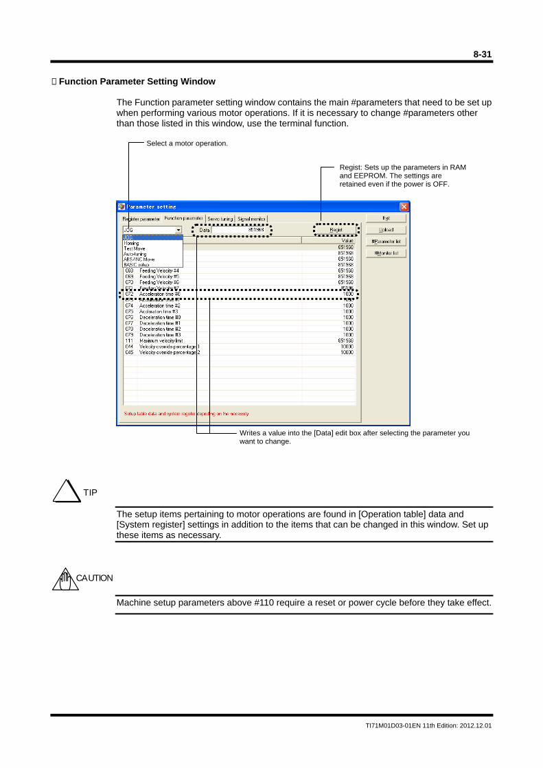
8-31
TI71M01D03-01EN 11th Edition: 2012.12.01
Function Parameter Setting Window
The Function parameter setting window contains the main #parameters that need to be set up when performing various motor operations. If it is necessary to change #parameters other than those listed in this window, use the terminal function.
The setup items pertaining to motor operations are found in [Operation table] data and [System register] settings in addition to the items that can be changed in this window. Set up these items as necessary.
Machine setup parameters above #110 require a reset or power cycle before they take effect.
Select a motor operation.
Regist: Sets up the parameters in RAM and EEPROM. The settings are retained even if the power is OFF.
Writes a value into the [Data] edit box after selecting the parameter you want to change.
TIP
CAUTION
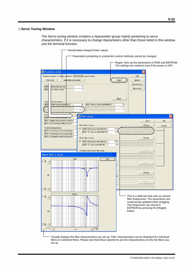
8-32
TI71M01D03-01EN 11th Edition: 2012.12.01
Servo Tuning Window
The Servo tuning window contains a #parameter group mainly pertaining to servo characteristics. If it is necessary to change #parameters other than those listed in this window, use the terminal function.
Recalculates integral limiter values.
Parameters pertaining to unselected control methods cannot be changed.
Regist: Sets up the parameters in RAM and EEPROM. The settings are retained even if the power is OFF.
This is a slide bar that sets up various filter frequencies. The parameters are continuously updated while dragging. The frequencies are stored in EEPROM by pressing the [Regist] button.
Visually displays the filter characteristics you set up. Filter characteristics can be displayed for individualfilters or combined filters. Please note that these waveforms are the characteristics of only the filters youset up.
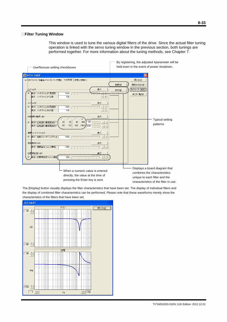
8-33
TI71M01D03-01EN 11th Edition: 2012.12.01
Filter Tuning Window
This window is used to tune the various digital filters of the drive. Since the actual filter tuning operation is linked with the servo tuning window in the previous section, both tunings are performed together. For more information about the tuning methods, see Chapter 7.
Use/Nonuse setting checkboxes
When a numeric value is entered
directly, the value at the time of
pressing the Enter key is sent.
Displays a board diagram that
combines the characteristics
unique to each filter and the
characteristics of the filter in use.
The [Display] button visually displays the filter characteristics that have been set. The display of individual filters and
the display of combined filter characteristics can be performed. Please note that these waveforms merely show the
characteristics of the filters that have been set.
By registering, the adjusted #parameter will be
held even in the event of power shutdown.
Typical setting
patterns
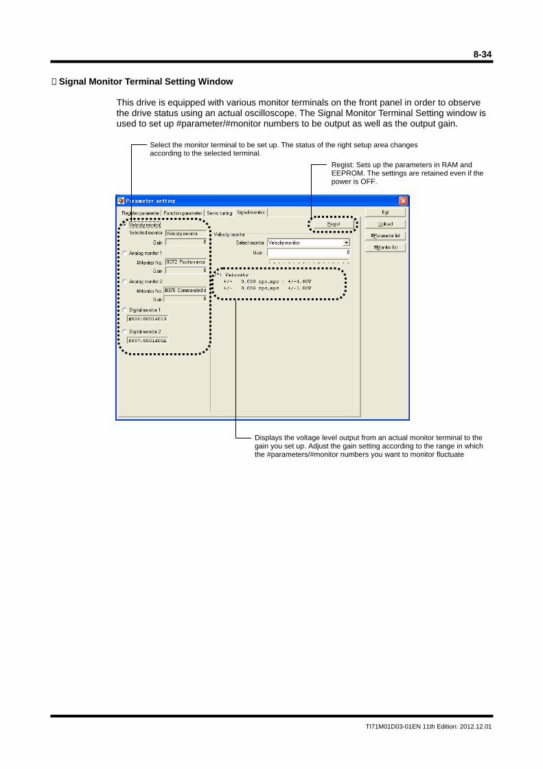
8-34
TI71M01D03-01EN 11th Edition: 2012.12.01
Signal Monitor Terminal Setting Window
This drive is equipped with various monitor terminals on the front panel in order to observe the drive status using an actual oscilloscope. The Signal Monitor Terminal Setting window is used to set up #parameter/#monitor numbers to be output as well as the output gain.
Select the monitor terminal to be set up. The status of the right setup area changes according to the selected terminal.
Regist: Sets up the parameters in RAM and EEPROM. The settings are retained even if the power is OFF.
Displays the voltage level output from an actual monitor terminal to the gain you set up. Adjust the gain setting according to the range in which the #parameters/#monitor numbers you want to monitor fluctuate
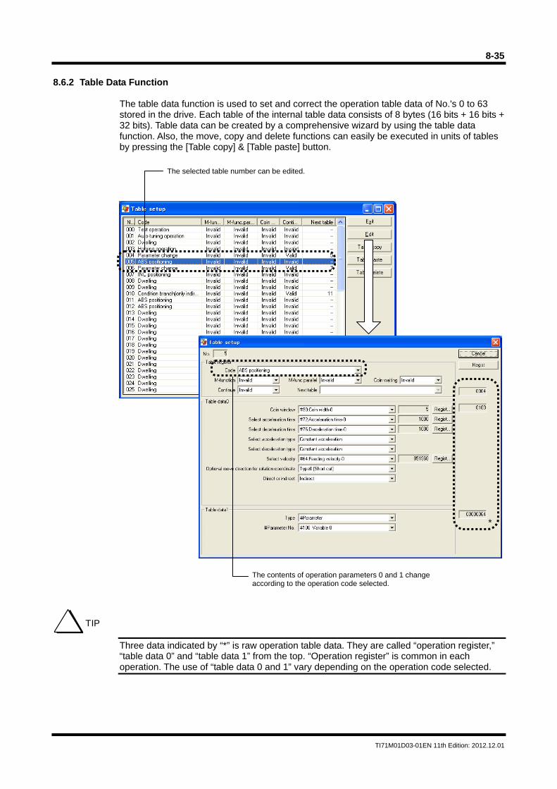
8-35
TI71M01D03-01EN 11th Edition: 2012.12.01
8.6.2 Table Data Function
The table data function is used to set and correct the operation table data of No.'s 0 to 63 stored in the drive. Each table of the internal table data consists of 8 bytes (16 bits + 16 bits + 32 bits). Table data can be created by a comprehensive wizard by using the table data function. Also, the move, copy and delete functions can easily be executed in units of tables by pressing the [Table copy] & [Table paste] button.
Three data indicated by “*” is raw operation table data. They are called “operation register,” “table data 0” and “table data 1” from the top. “Operation register” is common in each operation. The use of “table data 0 and 1” vary depending on the operation code selected.
The selected table number can be edited.
*
The contents of operation parameters 0 and 1 changeaccording to the operation code selected.
TIP
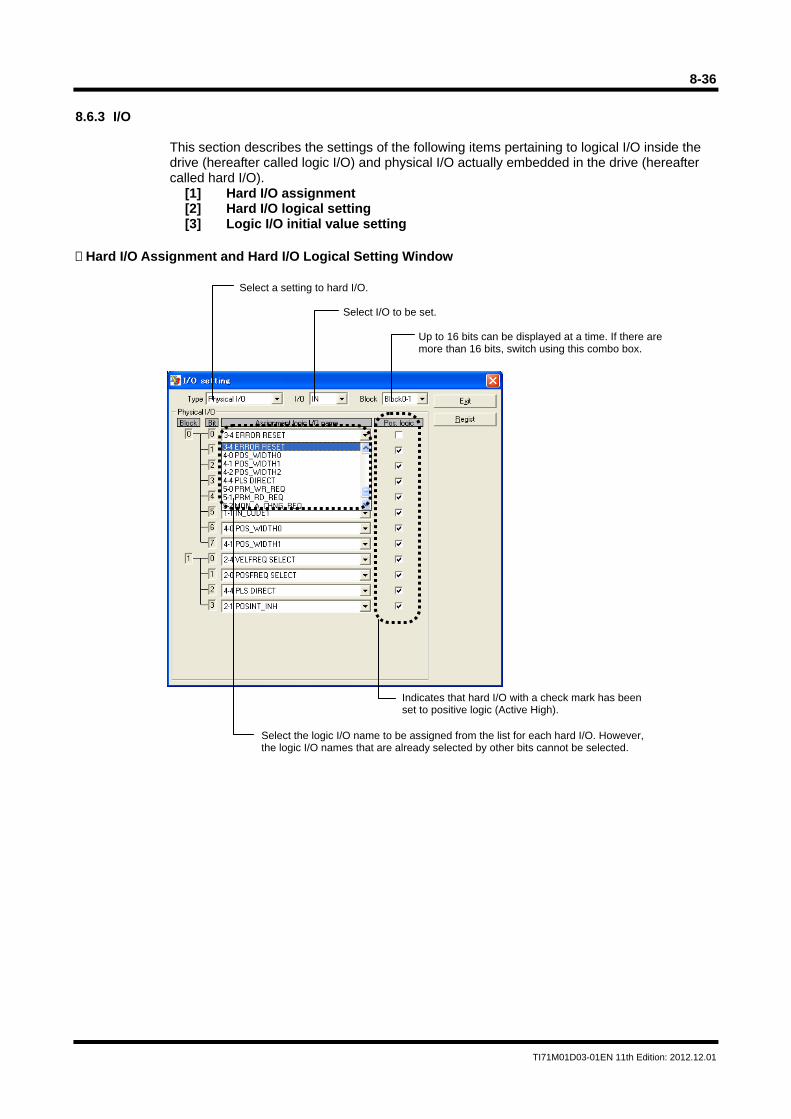
8-36
TI71M01D03-01EN 11th Edition: 2012.12.01
8.6.3 I/O
This section describes the settings of the following items pertaining to logical I/O inside the drive (hereafter called logic I/O) and physical I/O actually embedded in the drive (hereafter called hard I/O).
[1] Hard I/O assignment [2] Hard I/O logical setting [3] Logic I/O initial value setting
Hard I/O Assignment and Hard I/O Logical Setting Window
Select a setting to hard I/O.
Select I/O to be set.
Up to 16 bits can be displayed at a time. If there are more than 16 bits, switch using this combo box.
Indicates that hard I/O with a check mark has been set to positive logic (Active High).
Select the logic I/O name to be assigned from the list for each hard I/O. However, the logic I/O names that are already selected by other bits cannot be selected.
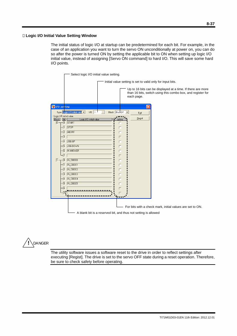
8-37
TI71M01D03-01EN 11th Edition: 2012.12.01
Logic I/O Initial Value Setting Window
The initial status of logic I/O at startup can be predetermined for each bit. For example, in the case of an application you want to turn the servo ON unconditionally at power on, you can do so after the power is turned ON by setting the applicable bit to ON when setting up logic I/O initial value, instead of assigning [Servo ON command] to hard I/O. This will save some hard I/O points.
The utility software issues a software reset to the drive in order to reflect settings after executing [Regist]. The drive is set to the servo OFF state during a reset operation. Therefore, be sure to check safety before operating.
Select logic I/O initial value setting.
Initial value setting is set to valid only for input bits.
Up to 16 bits can be displayed at a time. If there are more than 16 bits, switch using this combo box, and register for each page.
For bits with a check mark, initial values are set to ON.
A blank bit is a reserved bit, and thus not setting is allowed
! DANGER
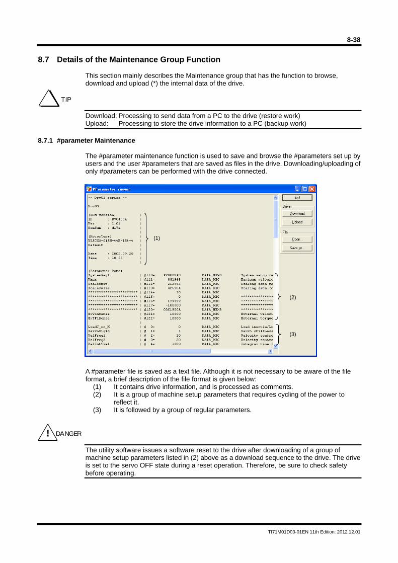
8-38
TI71M01D03-01EN 11th Edition: 2012.12.01
8.7 Details of the Maintenance Group Function
This section mainly describes the Maintenance group that has the function to browse, download and upload (*) the internal data of the drive.
Download: Processing to send data from a PC to the drive (restore work) Upload: Processing to store the drive information to a PC (backup work)
8.7.1 #parameter Maintenance
The #parameter maintenance function is used to save and browse the #parameters set up by users and the user #parameters that are saved as files in the drive. Downloading/uploading of only #parameters can be performed with the drive connected. A #parameter file is saved as a text file. Although it is not necessary to be aware of the file format, a brief description of the file format is given below:
(1) It contains drive information, and is processed as comments. (2) It is a group of machine setup parameters that requires cycling of the power to
reflect it. (3) It is followed by a group of regular parameters.
The utility software issues a software reset to the drive after downloading of a group of machine setup parameters listed in (2) above as a download sequence to the drive. The drive is set to the servo OFF state during a reset operation. Therefore, be sure to check safety before operating.
TIP
(1)
(2) (3)
! DANGER
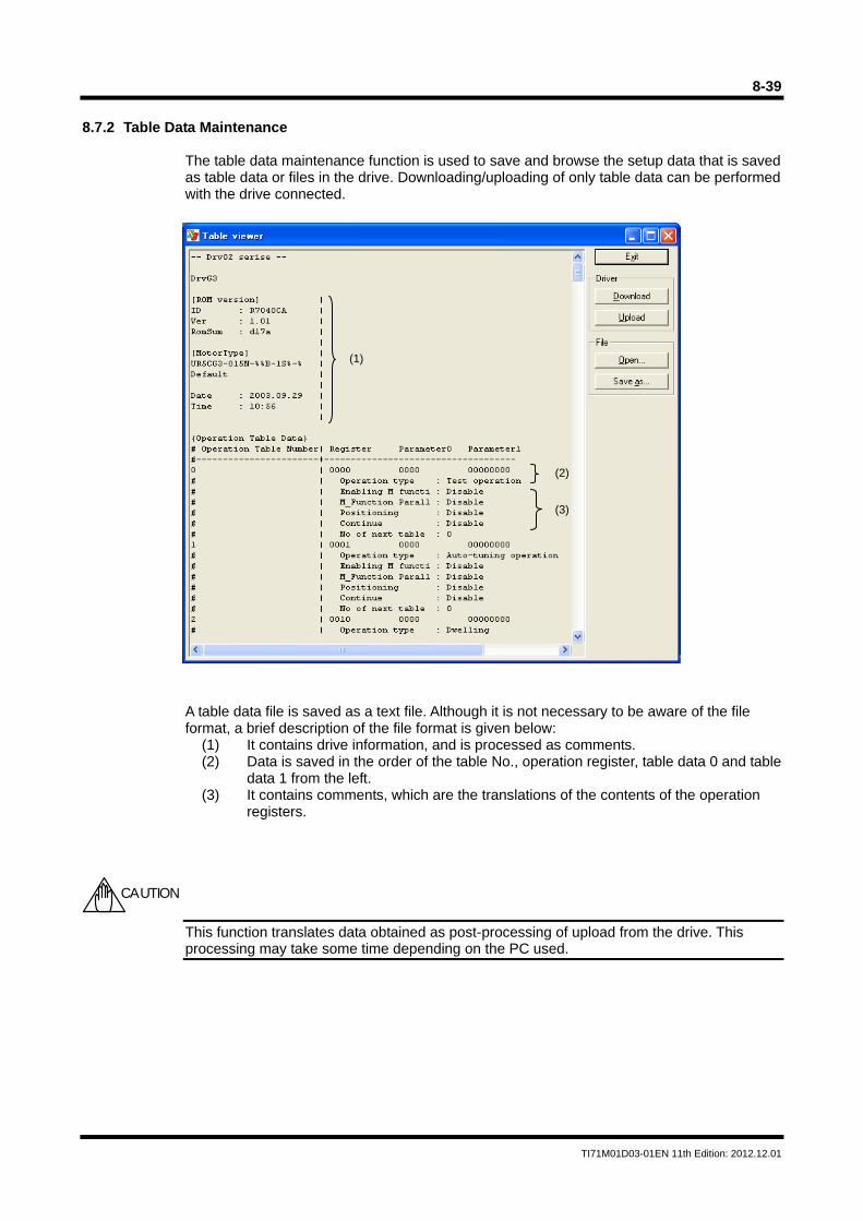
8-39
TI71M01D03-01EN 11th Edition: 2012.12.01
8.7.2 Table Data Maintenance
The table data maintenance function is used to save and browse the setup data that is saved as table data or files in the drive. Downloading/uploading of only table data can be performed with the drive connected.
A table data file is saved as a text file. Although it is not necessary to be aware of the file format, a brief description of the file format is given below:
(1) It contains drive information, and is processed as comments. (2) Data is saved in the order of the table No., operation register, table data 0 and table
data 1 from the left. (3) It contains comments, which are the translations of the contents of the operation
registers.
This function translates data obtained as post-processing of upload from the drive. This processing may take some time depending on the PC used.
(1)
(2) (3)
CAUTION
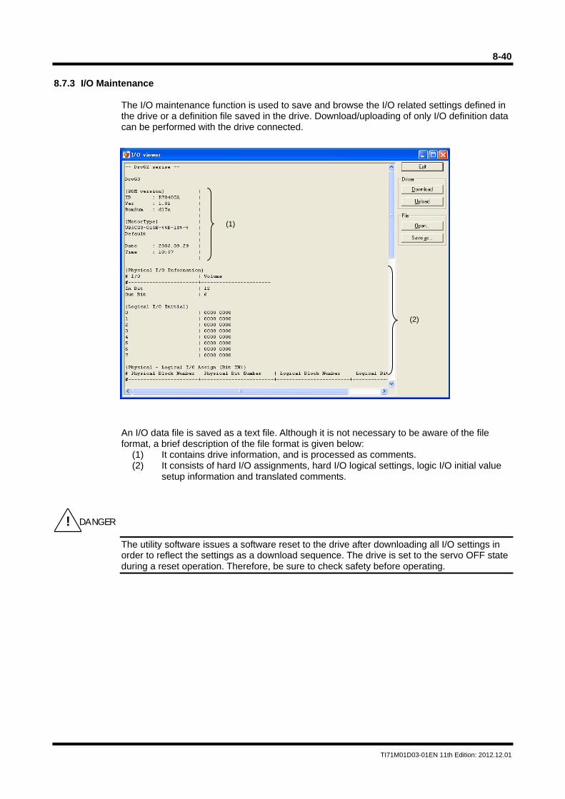
8-40
TI71M01D03-01EN 11th Edition: 2012.12.01
8.7.3 I/O Maintenance
The I/O maintenance function is used to save and browse the I/O related settings defined in the drive or a definition file saved in the drive. Download/uploading of only I/O definition data can be performed with the drive connected. An I/O data file is saved as a text file. Although it is not necessary to be aware of the file format, a brief description of the file format is given below:
(1) It contains drive information, and is processed as comments. (2) It consists of hard I/O assignments, hard I/O logical settings, logic I/O initial value
setup information and translated comments.
The utility software issues a software reset to the drive after downloading all I/O settings in order to reflect the settings as a download sequence. The drive is set to the servo OFF state during a reset operation. Therefore, be sure to check safety before operating.
(1)
(2)
! DANGER
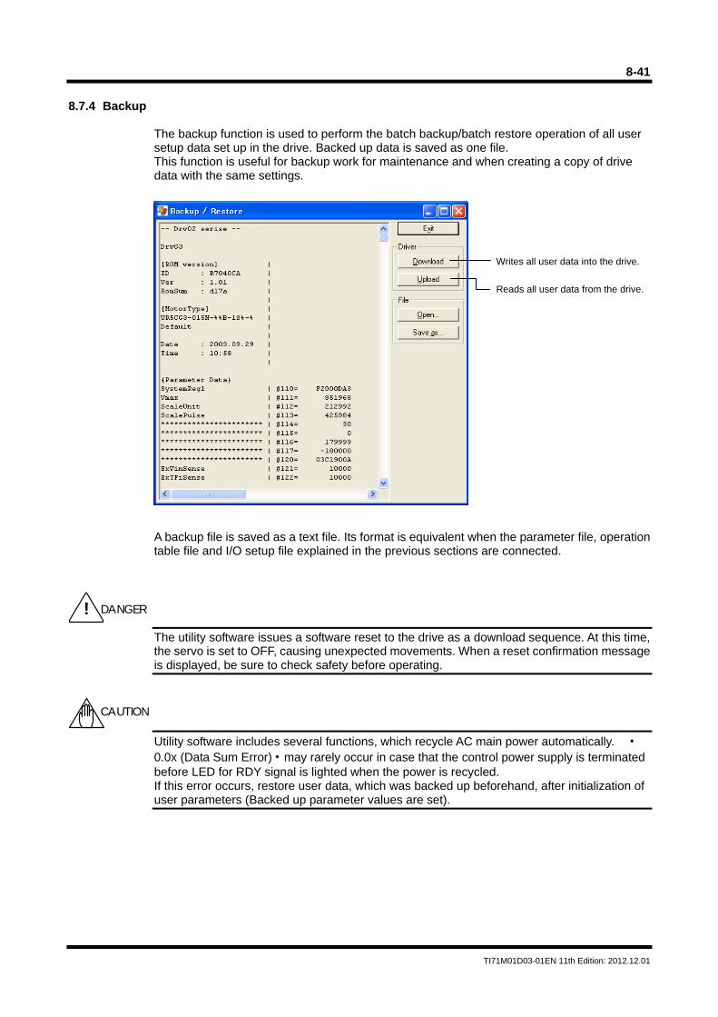
8-41
TI71M01D03-01EN 11th Edition: 2012.12.01
8.7.4 Backup
The backup function is used to perform the batch backup/batch restore operation of all user setup data set up in the drive. Backed up data is saved as one file. This function is useful for backup work for maintenance and when creating a copy of drive data with the same settings.
A backup file is saved as a text file. Its format is equivalent when the parameter file, operation table file and I/O setup file explained in the previous sections are connected.
The utility software issues a software reset to the drive as a download sequence. At this time, the servo is set to OFF, causing unexpected movements. When a reset confirmation message is displayed, be sure to check safety before operating.
Utility software includes several functions, which recycle AC main power automatically. ・0.0x (Data Sum Error)・may rarely occur in case that the control power supply is terminated before LED for RDY signal is lighted when the power is recycled. If this error occurs, restore user data, which was backed up beforehand, after initialization of user parameters (Backed up parameter values are set).
Writes all user data into the drive.
Reads all user data from the drive.
! DANGER
CAUTION
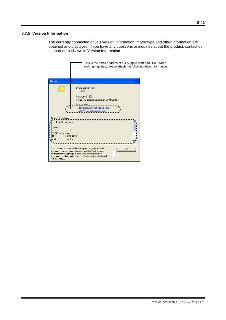
8-42
TI71M01D03-01EN 11th Edition: 2012.12.01
8.7.5 Version Information
The currently connected drive's version information, motor type and other information are obtained and displayed. If you have any questions or inquiries about the product, contact our support desk shown in Version Information.
This is the email address of our support staff and URL. When making inquiries, please attach the following drive information.
8-43
TI71M01D03-01EN 11th Edition: 2012.12.01
8.8 FAQ Pertaining to the Utility Software
This section describes the frequently asked questions (FAQ) pertaining to the utility software. Updated Parameters are not Stored.
Writing data to a parameter (e.g., #1=2) changes only that value in RAM of the drive. Therefore, that data is erased when the power is turned OFF. If you want to store updated data, rewrite the parameter in EEPROM (e.g., ##1=2), or write all parameters using the @16 command.
The Utility Software Stops during Waveform Display due to a Communication Error.
Insufficient performance of your PC may be the cause. Check if the operating conditions are met. Close all other applications if possible. Especially, if you are using the oscilloscope function, it uses up more CPU power than any other functions. If a communication error still occurs, change the communication cycle to a slower cycle. However, in such a case, the oscilloscope function cannot be used.
A Communication Error Occurs while Using the Oscilloscope Function for an Extended Period in
Windows 98.
Particularly in Windows 98, it seems there is a time contention problem between the power supply monitor interrupt and the communication port interrupt. When using the oscilloscope function, disable all power supply monitor related functions.
Waveforms Different from Expected Waveforms were Obtained when the Time Axis was set to a
Long Range.
Especially when the time axis is set to a long range, waveforms different from actual waveforms may be obtained especially relating to sampling. Always take account of an aliasing problem before using.
Communication Errors Occur Frequently on a USB-RS232C Converter.
Some converters may not operate correctly in this system. In particular, failure to receive data occurs with the frequently communicated oscilloscope function. Also, an error may occur during communication with the drive connected to the COM port of a PC due to the effect of the drive software's in the converter.
How can I Control the Drive from a PC Using an RS232C/485 Port?
We have control DLL for this purpose. You can create an application that controls multiple drives in Visual Basic from your PC by installing this control DLL. For more information, contact our Support Desk.
Installation Failed in Windows 98.
The utility software is supported in Windows 98 Second Edition or higher. How can I Update Various Resource Files?
We periodically update the PDF and CSV files referenced from the utility software. To update these files on your system, download the latest versions from our Web site and overwrite them into the install folder.

Blank Page
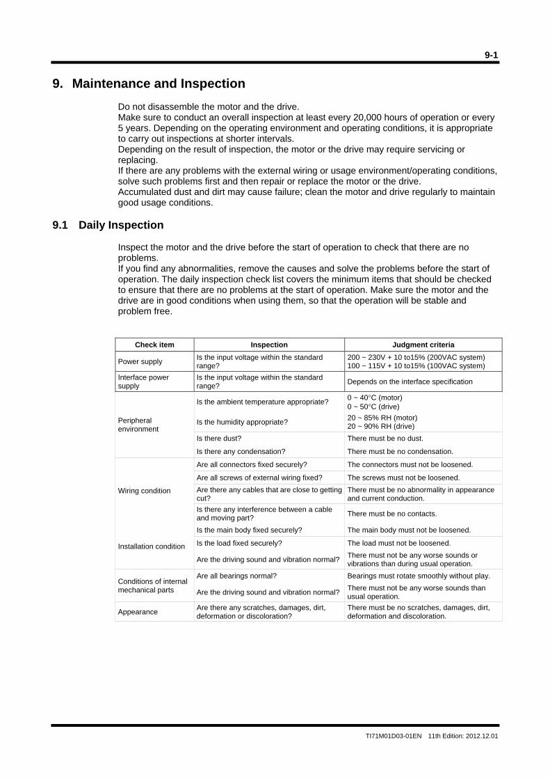
9-1
TI71M01D03-01EN 11th Edition: 2012.12.01
9. Maintenance and Inspection
Do not disassemble the motor and the drive. Make sure to conduct an overall inspection at least every 20,000 hours of operation or every 5 years. Depending on the operating environment and operating conditions, it is appropriate to carry out inspections at shorter intervals. Depending on the result of inspection, the motor or the drive may require servicing or replacing. If there are any problems with the external wiring or usage environment/operating conditions, solve such problems first and then repair or replace the motor or the drive. Accumulated dust and dirt may cause failure; clean the motor and drive regularly to maintain good usage conditions.
9.1 Daily Inspection
Inspect the motor and the drive before the start of operation to check that there are no problems. If you find any abnormalities, remove the causes and solve the problems before the start of operation. The daily inspection check list covers the minimum items that should be checked to ensure that there are no problems at the start of operation. Make sure the motor and the drive are in good conditions when using them, so that the operation will be stable and problem free.
Check item Inspection Judgment criteria
Power supply Is the input voltage within the standard range?
200 ~ 230V + 10 to15% (200VAC system) 100 ~ 115V + 10 to15% (100VAC system)
Interface power supply
Is the input voltage within the standard range?
Depends on the interface specification
Peripheral environment
Is the ambient temperature appropriate? 0 ~ 40°C (motor) 0 ~ 50°C (drive)
Is the humidity appropriate? 20 ~ 85% RH (motor) 20 ~ 90% RH (drive)
Is there dust? There must be no dust.
Is there any condensation? There must be no condensation.
Wiring condition
Are all connectors fixed securely? The connectors must not be loosened.
Are all screws of external wiring fixed? The screws must not be loosened.
Are there any cables that are close to getting cut?
There must be no abnormality in appearance and current conduction.
Is there any interference between a cable and moving part?
There must be no contacts.
Installation condition
Is the main body fixed securely? The main body must not be loosened.
Is the load fixed securely? The load must not be loosened.
Are the driving sound and vibration normal?There must not be any worse sounds or vibrations than during usual operation.
Conditions of internal mechanical parts
Are all bearings normal? Bearings must rotate smoothly without play.
Are the driving sound and vibration normal?There must not be any worse sounds than usual operation.
Appearance Are there any scratches, damages, dirt, deformation or discoloration?
There must be no scratches, damages, dirt, deformation and discoloration.
9-2
TI71M01D03-01EN 11th Edition: 2012.12.01
9.2 Backup and Restore Operations of User Data
It is recommended to back up user data to avoid data loss in case of accidents. Backed up data is useful when startup new devices. For example, it is possible to restore particular backed up data on several drives to use the same settings for each of them. Backup and restore operations can be performed using the following methods.
Backup and Restore Operations Using the Utility Software
By backing up user data using the utility software, the data can be saved as electronic files. See Section 8.7.4, "Backup" for more information.
Backup and Restore Operations Using the Operation Display Pendant (Optional)
By backing up user data using the operation display pendant, the data can be saved in the embedded EEPROM of the operation display pendant. User data for multiple drives can be stored without using other external devices. See the technical document of the operation display pendant for more information.
9.3 Initialization of User Data (Reset All)
[Reset All] refers to returning all user data to the settings at the time of shipment from the factory. Perform [Reset All] when you want to redo the drive settings from the scratch.
Operating Procedure The reset all operation can be performed only by entering the designated command in [Terminal Function] of the utility software or [Terminal Function] of the operation display panel in order to prevent an erroneous operation. Erroneous operation can also be prevented by requiring a password with command. The command format is as follows.
@90 : 2003
Password
A part of machine parameters overwrites the related parameters when the power is recycled, if those parameters are changed. ・0.0x (Data Sum Error)・may rarely occur in case that the control power supply is terminated before LED for RDY signal is lighted when the power is recycled. If this error occurs, restore user data, which was backed up beforehand, after initialization of user parameters (Backed up parameter values are set).
CAUTION
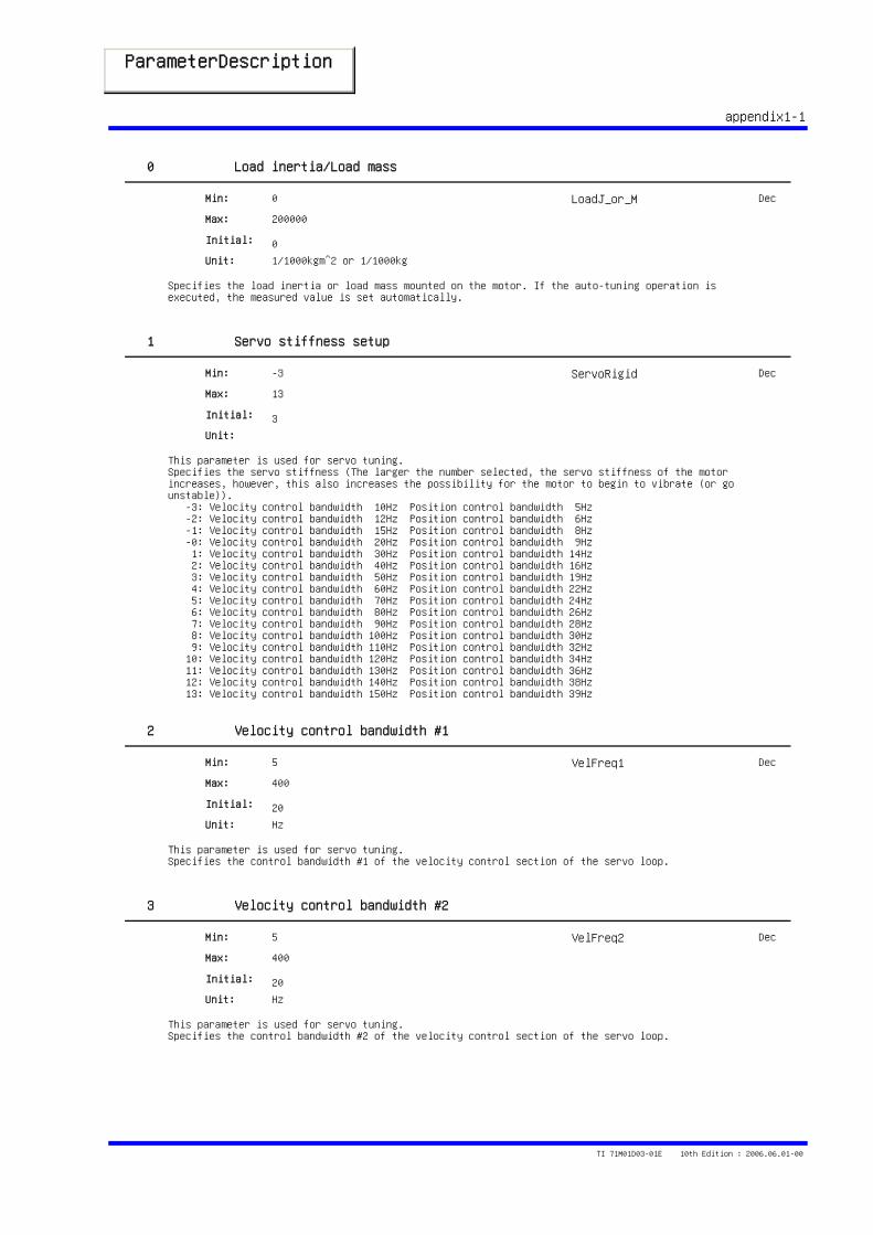
ParameterDescription STD1
appendix1-1
0 Load inertia/Load mass
Specifies the load inertia or load mass mounted on the motor. If the auto-tuning operation is executed, the measured value is set automatically.
0
200000
0
Min:
Max:
Initial:
Unit: 1/1000kgm^2 or 1/1000kg
LoadJ_or_M Dec
1 Servo stiffness setup
This parameter is used for servo tuning.Specifies the servo stiffness (The larger the number selected, the servo stiffness of the motor increases, however, this also increases the possibility for the motor to begin to vibrate (or go unstable)). -3: Velocity control bandwidth 10Hz Position control bandwidth 5Hz -2: Velocity control bandwidth 12Hz Position control bandwidth 6Hz -1: Velocity control bandwidth 15Hz Position control bandwidth 8Hz -0: Velocity control bandwidth 20Hz Position control bandwidth 9Hz 1: Velocity control bandwidth 30Hz Position control bandwidth 14Hz 2: Velocity control bandwidth 40Hz Position control bandwidth 16Hz 3: Velocity control bandwidth 50Hz Position control bandwidth 19Hz 4: Velocity control bandwidth 60Hz Position control bandwidth 22Hz 5: Velocity control bandwidth 70Hz Position control bandwidth 24Hz 6: Velocity control bandwidth 80Hz Position control bandwidth 26Hz 7: Velocity control bandwidth 90Hz Position control bandwidth 28Hz 8: Velocity control bandwidth 100Hz Position control bandwidth 30Hz 9: Velocity control bandwidth 110Hz Position control bandwidth 32Hz 10: Velocity control bandwidth 120Hz Position control bandwidth 34Hz 11: Velocity control bandwidth 130Hz Position control bandwidth 36Hz 12: Velocity control bandwidth 140Hz Position control bandwidth 38Hz 13: Velocity control bandwidth 150Hz Position control bandwidth 39Hz
-3
13
3
Min:
Max:
Initial:
Unit:
ServoRigid Dec
2 Velocity control bandwidth #1
This parameter is used for servo tuning.Specifies the control bandwidth #1 of the velocity control section of the servo loop.
5
400
20
Min:
Max:
Initial:
Unit: Hz
VelFreq1 Dec
3 Velocity control bandwidth #2
This parameter is used for servo tuning.Specifies the control bandwidth #2 of the velocity control section of the servo loop.
5
400
20
Min:
Max:
Initial:
Unit: Hz
VelFreq2 Dec
TI 71M01D03-01E 10th Edition : 2006.06.01-00
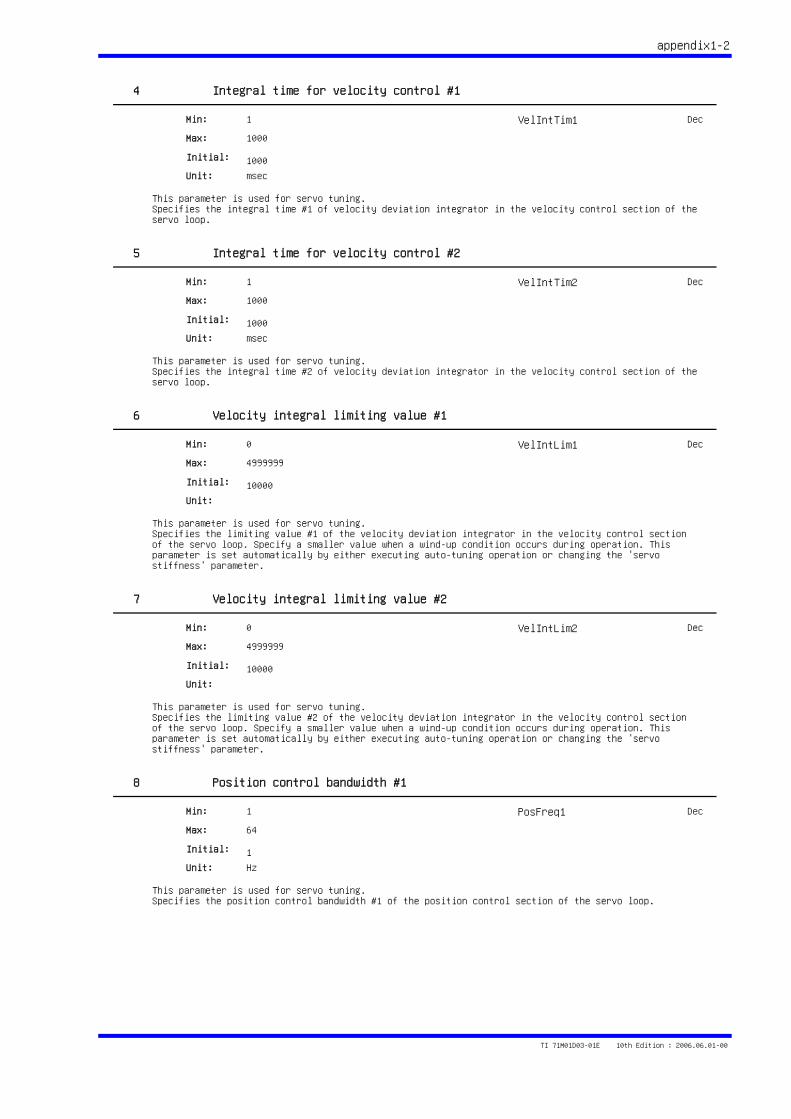
appendix1-2
4 Integral time for velocity control #1
This parameter is used for servo tuning.Specifies the integral time #1 of velocity deviation integrator in the velocity control section of the servo loop.
1
1000
1000
Min:
Max:
Initial:
Unit: msec
VelIntTim1 Dec
5 Integral time for velocity control #2
This parameter is used for servo tuning.Specifies the integral time #2 of velocity deviation integrator in the velocity control section of the servo loop.
1
1000
1000
Min:
Max:
Initial:
Unit: msec
VelIntTim2 Dec
6 Velocity integral limiting value #1
This parameter is used for servo tuning.Specifies the limiting value #1 of the velocity deviation integrator in the velocity control section of the servo loop. Specify a smaller value when a wind-up condition occurs during operation. This parameter is set automatically by either executing auto-tuning operation or changing the 'servo stiffness' parameter.
0
4999999
10000
Min:
Max:
Initial:
Unit:
VelIntLim1 Dec
7 Velocity integral limiting value #2
This parameter is used for servo tuning.Specifies the limiting value #2 of the velocity deviation integrator in the velocity control section of the servo loop. Specify a smaller value when a wind-up condition occurs during operation. This parameter is set automatically by either executing auto-tuning operation or changing the 'servo stiffness' parameter.
0
4999999
10000
Min:
Max:
Initial:
Unit:
VelIntLim2 Dec
8 Position control bandwidth #1
This parameter is used for servo tuning.Specifies the position control bandwidth #1 of the position control section of the servo loop.
1
64
1
Min:
Max:
Initial:
Unit: Hz
PosFreq1 Dec
TI 71M01D03-01E 10th Edition : 2006.06.01-00
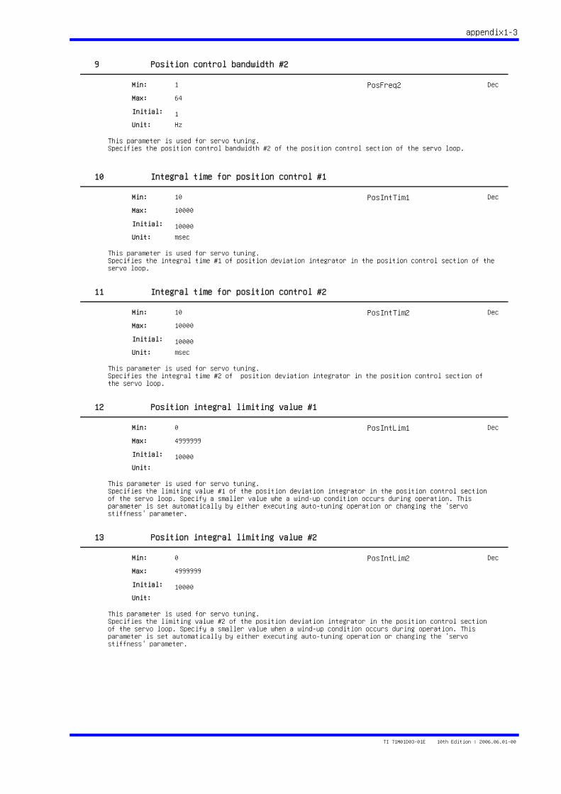
appendix1-3
9 Position control bandwidth #2
This parameter is used for servo tuning.Specifies the position control bandwidth #2 of the position control section of the servo loop.
1
64
1
Min:
Max:
Initial:
Unit: Hz
PosFreq2 Dec
10 Integral time for position control #1
This parameter is used for servo tuning.Specifies the integral time #1 of position deviation integrator in the position control section of the servo loop.
10
10000
10000
Min:
Max:
Initial:
Unit: msec
PosIntTim1 Dec
11 Integral time for position control #2
This parameter is used for servo tuning.Specifies the integral time #2 of position deviation integrator in the position control section of the servo loop.
10
10000
10000
Min:
Max:
Initial:
Unit: msec
PosIntTim2 Dec
12 Position integral limiting value #1
This parameter is used for servo tuning.Specifies the limiting value #1 of the position deviation integrator in the position control section of the servo loop. Specify a smaller value whe a wind-up condition occurs during operation. This parameter is set automatically by either executing auto-tuning operation or changing the 'servo stiffness' parameter.
0
4999999
10000
Min:
Max:
Initial:
Unit:
PosIntLim1 Dec
13 Position integral limiting value #2
This parameter is used for servo tuning.Specifies the limiting value #2 of the position deviation integrator in the position control section of the servo loop. Specify a smaller value when a wind-up condition occurs during operation. This parameter is set automatically by either executing auto-tuning operation or changing the 'servo stiffness' parameter.
0
4999999
10000
Min:
Max:
Initial:
Unit:
PosIntLim2 Dec
TI 71M01D03-01E 10th Edition : 2006.06.01-00
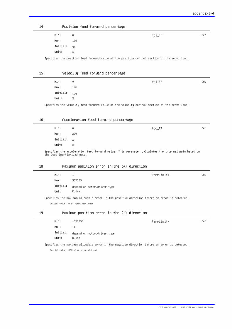
appendix1-4
14 Position feed forward percentage
Specifies the position feed forward value of the position control section of the servo loop.
0
126
90
Min:
Max:
Initial:
Unit: %
Pos_FF Dec
15 Velocity feed forward percentage
Specifies the velocity feed forward value of the velocity control section of the servo loop.
0
126
100
Min:
Max:
Initial:
Unit: %
Vel_FF Dec
16 Acceleration feed forward percentage
Specifies the acceleration feed forward value. This parameter calculates the internal gain based on the load inertia/load mass.
0
200
0
Min:
Max:
Initial:
Unit: %
Acc_FF Dec
18 Maximum position error in the (+) direction
Specifies the maximum allowable error in the positive direction before an error is detected.
1
999999
depend on motor.driver type
Min:
Max:
Initial:
Unit: Pulse
Initial value: 5% of motor resolution
PerrLimit+ Dec
19 Maximum position error in the (-) direction
Specifies the maximum allowable error in the negative direction before an error is detected.
-999999
-1
depend on motor.driver type
Min:
Max:
Initial:
Unit: pulse
Initial value: -(5% of motor resolution)
PerrLimit- Dec
TI 71M01D03-01E 10th Edition : 2006.06.01-00
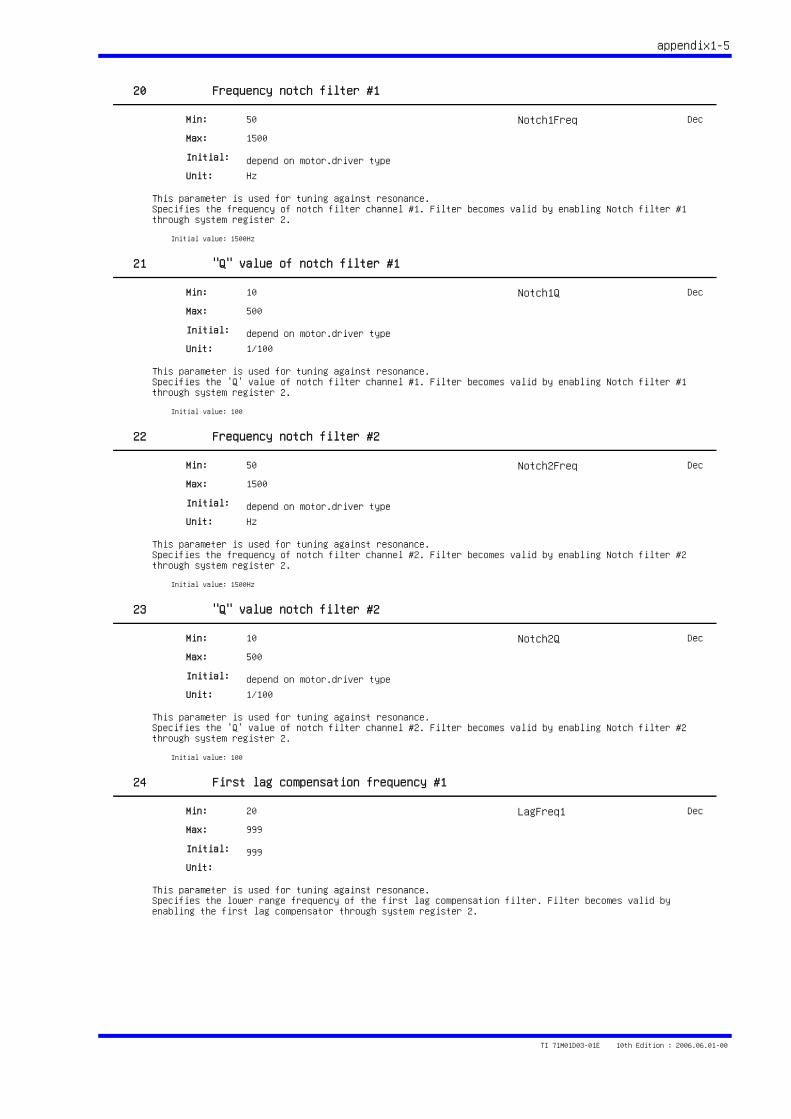
appendix1-5
20 Frequency notch filter #1
This parameter is used for tuning against resonance.Specifies the frequency of notch filter channel #1. Filter becomes valid by enabling Notch filter #1 through system register 2.
50
1500
depend on motor.driver type
Min:
Max:
Initial:
Unit: Hz
Initial value: 1500Hz
Notch1Freq Dec
21 "Q" value of notch filter #1
This parameter is used for tuning against resonance.Specifies the 'Q' value of notch filter channel #1. Filter becomes valid by enabling Notch filter #1 through system register 2.
10
500
depend on motor.driver type
Min:
Max:
Initial:
Unit: 1/100
Initial value: 100
Notch1Q Dec
22 Frequency notch filter #2
This parameter is used for tuning against resonance.Specifies the frequency of notch filter channel #2. Filter becomes valid by enabling Notch filter #2 through system register 2.
50
1500
depend on motor.driver type
Min:
Max:
Initial:
Unit: Hz
Initial value: 1500Hz
Notch2Freq Dec
23 "Q" value notch filter #2
This parameter is used for tuning against resonance.Specifies the 'Q' value of notch filter channel #2. Filter becomes valid by enabling Notch filter #2 through system register 2.
10
500
depend on motor.driver type
Min:
Max:
Initial:
Unit: 1/100
Initial value: 100
Notch2Q Dec
24 First lag compensation frequency #1
This parameter is used for tuning against resonance.Specifies the lower range frequency of the first lag compensation filter. Filter becomes valid by enabling the first lag compensator through system register 2.
20
999
999
Min:
Max:
Initial:
Unit:
LagFreq1 Dec
TI 71M01D03-01E 10th Edition : 2006.06.01-00
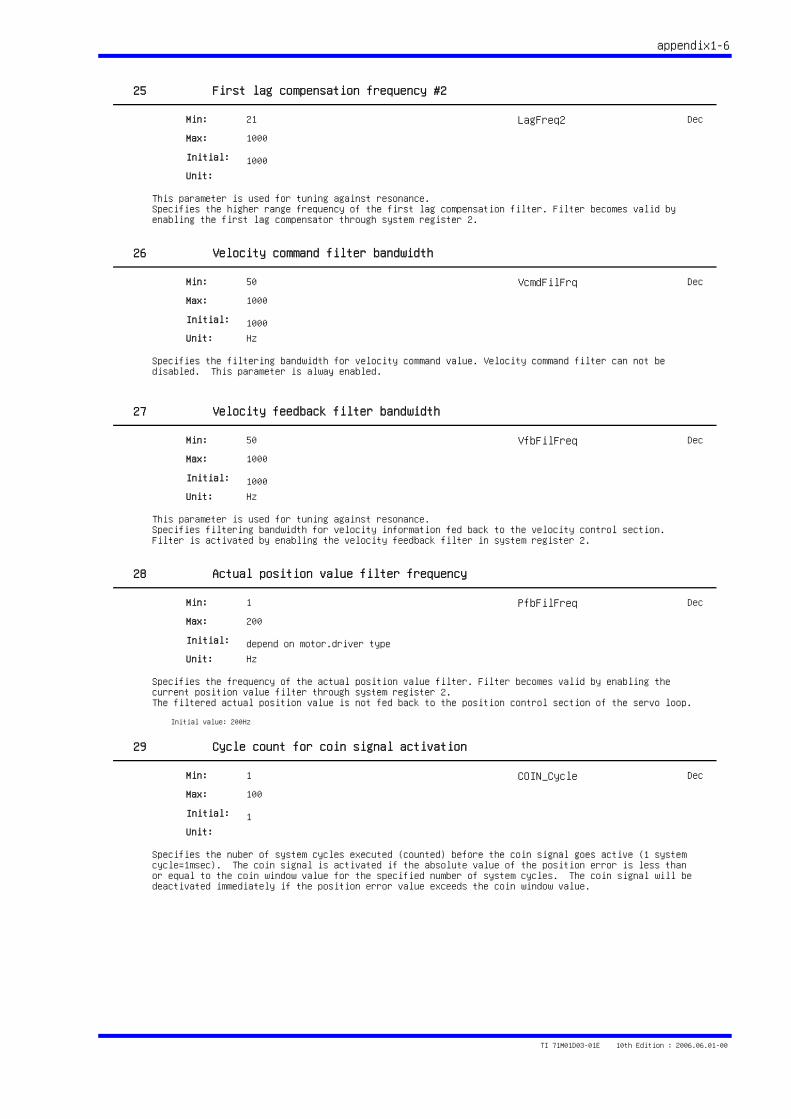
appendix1-6
25 First lag compensation frequency #2
This parameter is used for tuning against resonance.Specifies the higher range frequency of the first lag compensation filter. Filter becomes valid by enabling the first lag compensator through system register 2.
21
1000
1000
Min:
Max:
Initial:
Unit:
LagFreq2 Dec
26 Velocity command filter bandwidth
Specifies the filtering bandwidth for velocity command value. Velocity command filter can not be disabled. This parameter is alway enabled.
50
1000
1000
Min:
Max:
Initial:
Unit: Hz
VcmdFilFrq Dec
27 Velocity feedback filter bandwidth
This parameter is used for tuning against resonance.Specifies filtering bandwidth for velocity information fed back to the velocity control section. Filter is activated by enabling the velocity feedback filter in system register 2.
50
1000
1000
Min:
Max:
Initial:
Unit: Hz
VfbFilFreq Dec
28 Actual position value filter frequency
Specifies the frequency of the actual position value filter. Filter becomes valid by enabling the current position value filter through system register 2.The filtered actual position value is not fed back to the position control section of the servo loop.
1
200
depend on motor.driver type
Min:
Max:
Initial:
Unit: Hz
Initial value: 200Hz
PfbFilFreq Dec
29 Cycle count for coin signal activation
Specifies the nuber of system cycles executed (counted) before the coin signal goes active (1 system cycle=1msec). The coin signal is activated if the absolute value of the position error is less than or equal to the coin window value for the specified number of system cycles. The coin signal will be deactivated immediately if the position error value exceeds the coin window value.
1
100
1
Min:
Max:
Initial:
Unit:
COIN_Cycle Dec
TI 71M01D03-01E 10th Edition : 2006.06.01-00
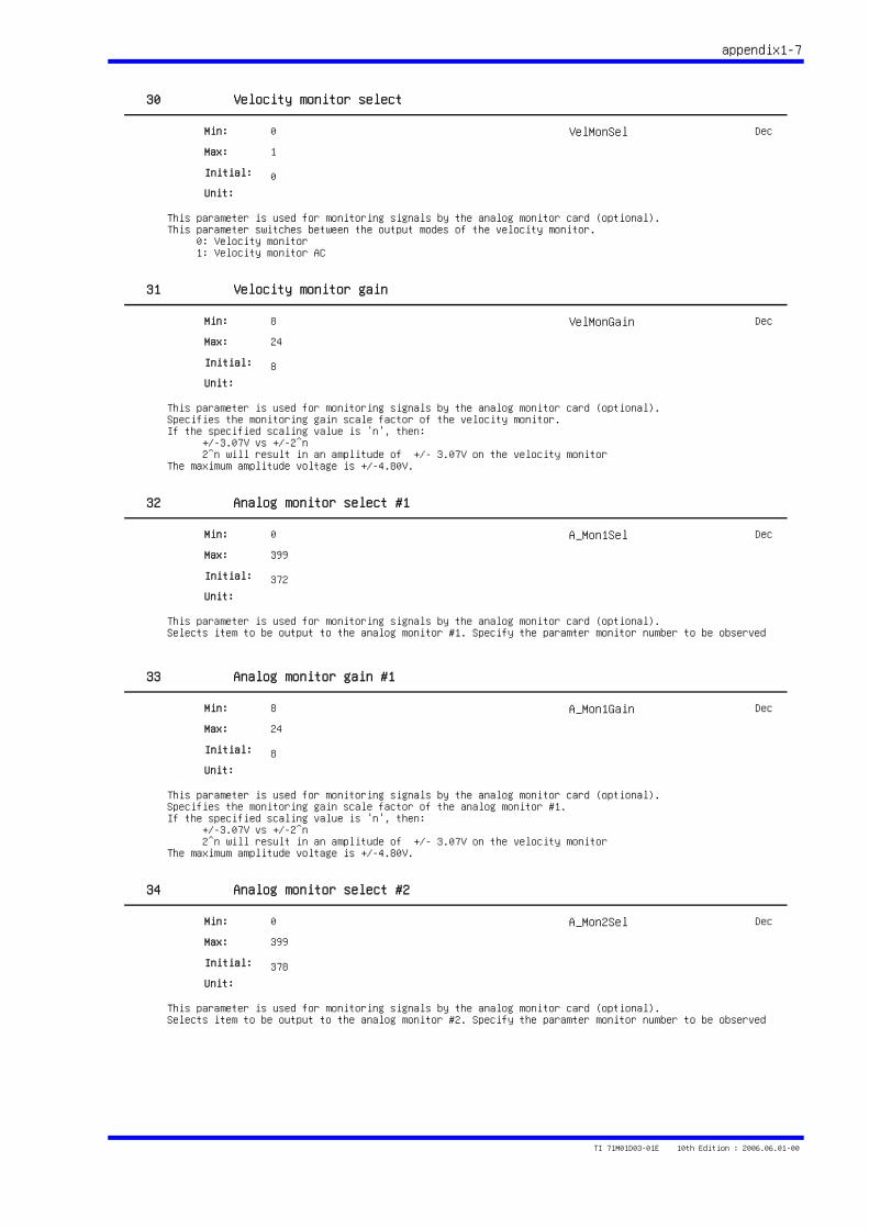
appendix1-7
30 Velocity monitor select
This parameter is used for monitoring signals by the analog monitor card (optional).This parameter switches between the output modes of the velocity monitor. 0: Velocity monitor 1: Velocity monitor AC
0
1
0
Min:
Max:
Initial:
Unit:
VelMonSel Dec
31 Velocity monitor gain
This parameter is used for monitoring signals by the analog monitor card (optional).Specifies the monitoring gain scale factor of the velocity monitor.If the specified scaling value is 'n', then: +/-3.07V vs +/-2^n 2^n will result in an amplitude of +/- 3.07V on the velocity monitorThe maximum amplitude voltage is +/-4.80V.
8
24
8
Min:
Max:
Initial:
Unit:
VelMonGain Dec
32 Analog monitor select #1
This parameter is used for monitoring signals by the analog monitor card (optional).Selects item to be output to the analog monitor #1. Specify the paramter monitor number to be observed
0
399
372
Min:
Max:
Initial:
Unit:
A_Mon1Sel Dec
33 Analog monitor gain #1
This parameter is used for monitoring signals by the analog monitor card (optional).Specifies the monitoring gain scale factor of the analog monitor #1.If the specified scaling value is 'n', then: +/-3.07V vs +/-2^n 2^n will result in an amplitude of +/- 3.07V on the velocity monitorThe maximum amplitude voltage is +/-4.80V.
8
24
8
Min:
Max:
Initial:
Unit:
A_Mon1Gain Dec
34 Analog monitor select #2
This parameter is used for monitoring signals by the analog monitor card (optional).Selects item to be output to the analog monitor #2. Specify the paramter monitor number to be observed
0
399
378
Min:
Max:
Initial:
Unit:
A_Mon2Sel Dec
TI 71M01D03-01E 10th Edition : 2006.06.01-00
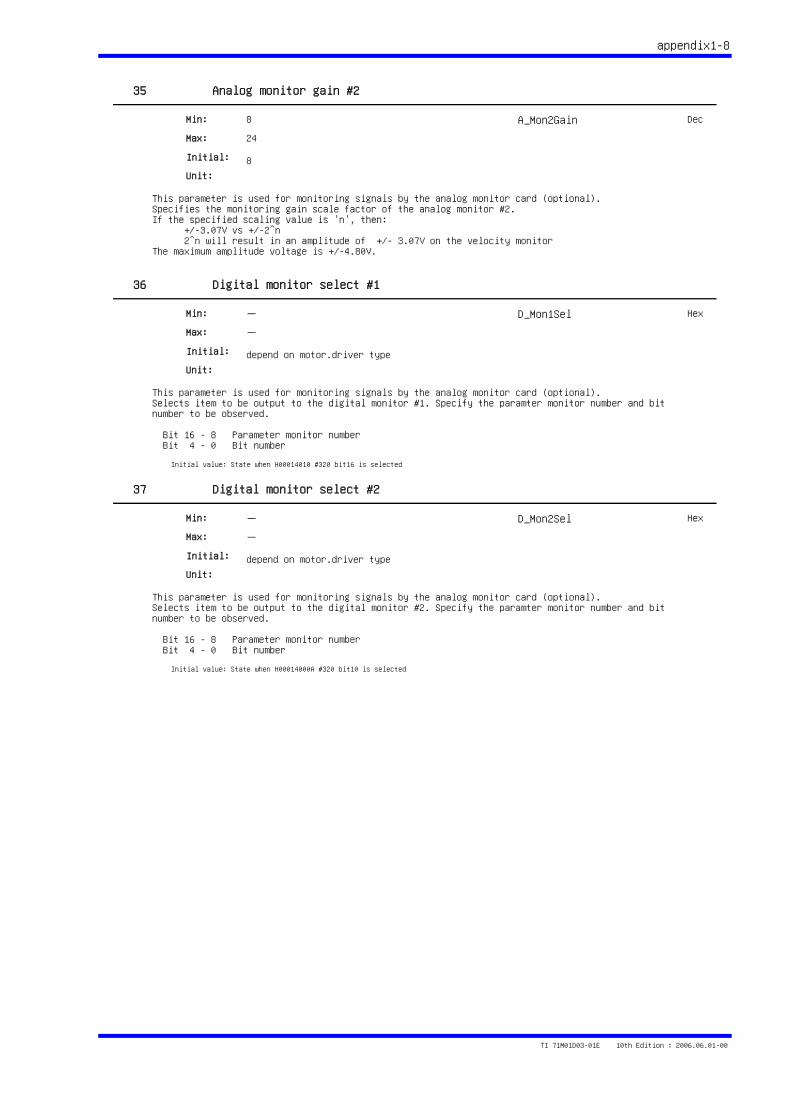
appendix1-8
35 Analog monitor gain #2
This parameter is used for monitoring signals by the analog monitor card (optional).Specifies the monitoring gain scale factor of the analog monitor #2.If the specified scaling value is 'n', then: +/-3.07V vs +/-2^n 2^n will result in an amplitude of +/- 3.07V on the velocity monitorThe maximum amplitude voltage is +/-4.80V.
8
24
8
Min:
Max:
Initial:
Unit:
A_Mon2Gain Dec
36 Digital monitor select #1
This parameter is used for monitoring signals by the analog monitor card (optional).Selects item to be output to the digital monitor #1. Specify the paramter monitor number and bit number to be observed.
Bit 16 - 8 Parameter monitor number Bit 4 - 0 Bit number
-
-
depend on motor.driver type
Min:
Max:
Initial:
Unit:
Initial value: State when H00014010 #320 bit16 is selected
D_Mon1Sel Hex
37 Digital monitor select #2
This parameter is used for monitoring signals by the analog monitor card (optional).Selects item to be output to the digital monitor #2. Specify the paramter monitor number and bit number to be observed.
Bit 16 - 8 Parameter monitor number Bit 4 - 0 Bit number
-
-
depend on motor.driver type
Min:
Max:
Initial:
Unit:
Initial value: State when H00014000A #320 bit10 is selected
D_Mon2Sel Hex
TI 71M01D03-01E 10th Edition : 2006.06.01-00
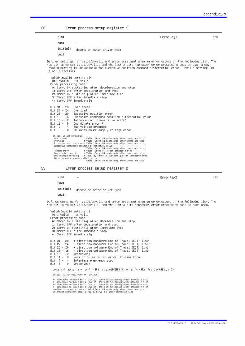
appendix1-9
38 Error process setup register 1
Defines settings for valid/invalid and error treatment when an error occurs in the following list. The top bit is to set valid/invalid, and the last 3 bits represent error processing code in each area. Invalid setting is unavailable for excessive position command differential error (Invalid setting (0) is not effective).
Valid/Invalid setting bit 0: Invalid 1: Valid Error processing code 0: Servo ON sustaining after deceleration and stop 1: Servo OFF after deceleration and stop 2: Servo ON sustainnig after immediate stop 3: Servo OFF after immediate stop 4: Servo OFF immediately
Bit 31 - 28 Over speed Bit 27 - 24 Overload Bit 23 - 20 Excessive position error Bit 19 - 16 Excessive commanded position differential value Bit 15 - 12 Tandem error (Slave drive error) Bit 11 - 8 Coordinate error A Bit 7 - 4 Bus voltage dropping Bit 3 - 0 AC mains power supply voltage error
-
-
depend on motor.driver type
Min:
Max:
Initial:
Unit:
Initial value: HAAAABA2A Over speed : Valid, Servo ON sustainnig after immediate stop Overload : Valid, Servo ON sustainnig after immediate stop Excessive position error: Valid, Servo ON sustainnig after immediate stop Excessive commanded position differential value: Valid, Servo ON sustainnig after immediate stop Tandem error : Valid, Servo OFF after immediate stop Coordinate error A : Valid, Servo ON sustainnig after immediate stop Bus voltage dropping : Invalid, Servo ON sustainnig after immediate stop AC mains power supply voltage error: Valid, Servo ON sustainnig after immediate stop
ErrorReg1 Hex
39 Error process setup register 2
Defines settings for valid/invalid and error treatment when an error occurs in the following list. The top bit is to set valid/invalid, and the last 3 bits represent error processing code in each area.
Valid/Invalid setting bit 0: Invalid 1: Valid Error processing code 0: Servo ON sustaining after deceleration and stop 1: Servo OFF after deceleration and stop 2: Servo ON sustainnig after immediate stop 3: Servo OFF after immediate stop 4: Servo OFF immediately
Bit 31 - 28 + direction hardware End of Travel (EOT) limit Bit 27 - 24 - direction hardware End of Travel (EOT) limit Bit 23 - 20 + direction software End of Travel (EOT) limit Bit 19 - 16 - direction software End of Travel (EOT) limit Bit 15 - 12 (reserved) Bit 11 - 8 Monitor pulse output error・CC-Link Error Bit 7 - 4 Interface emergency stop Bit 3 - 0 (reserved)
-
-
depend on motor.driver type
Min:
Max:
Initial:
Unit:
DrvGⅢでは、Bit11~ 8 モニタパルス異常・CC-Link通信異常は、モニタパルス異常に対してのみ機能します。
Initial value: H2222*ab* (*: unfixed)
(+)direction hardware EOT : Invalid, Servo ON sustainnig after immediate stop(-)direction hardware EOT : Invalid, Servo ON sustainnig after immediate stop(+)direction software EOT : Invalid, Servo ON sustainnig after immediate stop(-)direction software EOT : Invalid, Servo ON sustainnig after immediate stopMonitor pulse output error: Valid Servo ON sustainnig after immediate stopInterface emergency stop : Valid, Servo OFF after immediate stop
ErrorReg2 Hex
TI 71M01D03-01E 10th Edition : 2006.06.01-00
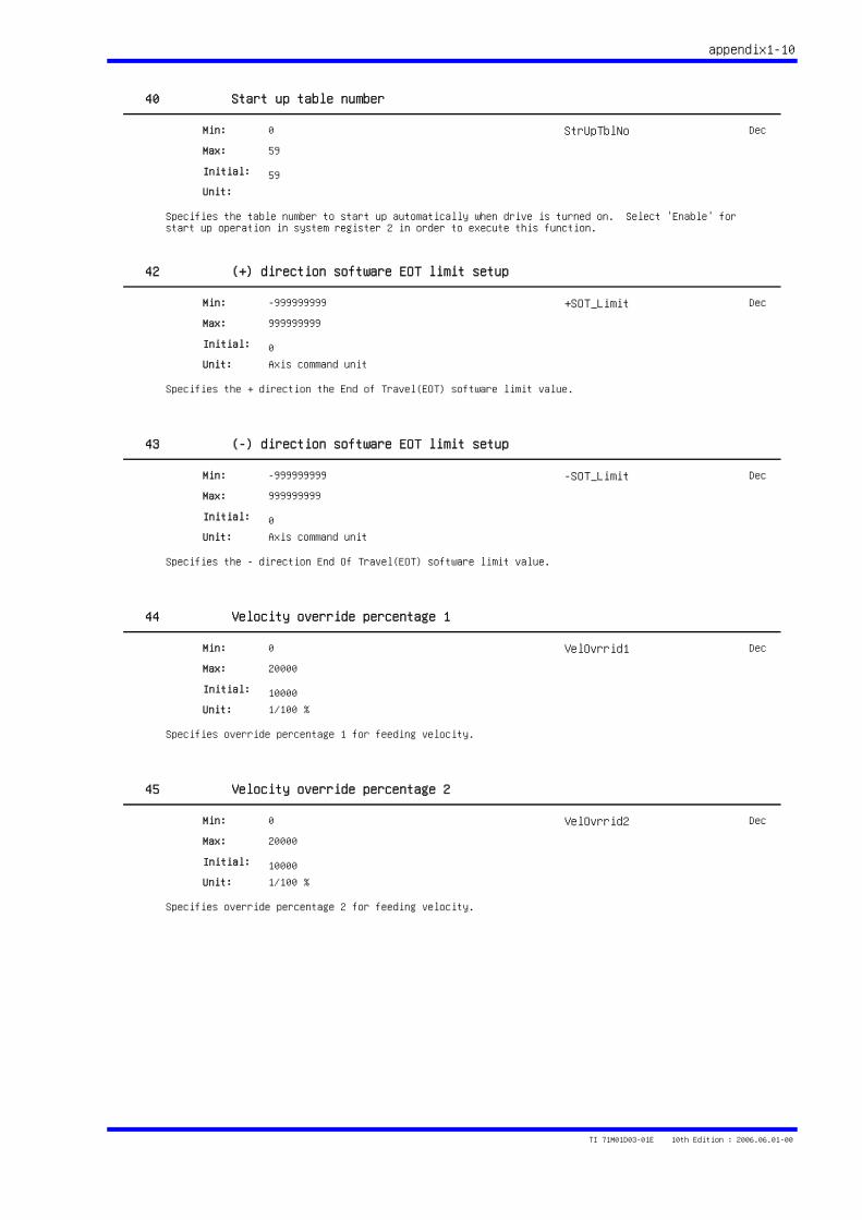
appendix1-10
40 Start up table number
Specifies the table number to start up automatically when drive is turned on. Select 'Enable' for start up operation in system register 2 in order to execute this function.
0
59
59
Min:
Max:
Initial:
Unit:
StrUpTblNo Dec
42 (+) direction software EOT limit setup
Specifies the + direction the End of Travel(EOT) software limit value.
-999999999
999999999
0
Min:
Max:
Initial:
Unit: Axis command unit
+SOT_Limit Dec
43 (-) direction software EOT limit setup
Specifies the - direction End Of Travel(EOT) software limit value.
-999999999
999999999
0
Min:
Max:
Initial:
Unit: Axis command unit
-SOT_Limit Dec
44 Velocity override percentage 1
Specifies override percentage 1 for feeding velocity.
0
20000
10000
Min:
Max:
Initial:
Unit: 1/100 %
VelOvrrid1 Dec
45 Velocity override percentage 2
Specifies override percentage 2 for feeding velocity.
0
20000
10000
Min:
Max:
Initial:
Unit: 1/100 %
VelOvrrid2 Dec
TI 71M01D03-01E 10th Edition : 2006.06.01-00
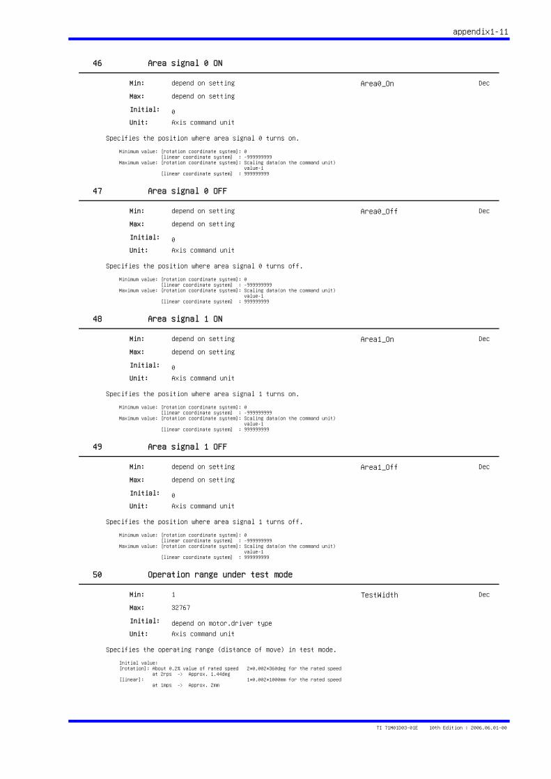
appendix1-11
46 Area signal 0 ON
Specifies the position where area signal 0 turns on.
depend on setting
depend on setting
0
Min:
Max:
Initial:
Unit: Axis command unit
Minimum value: [rotation coordinate system]: 0 [linear coordinate system] : -999999999Maximum value: [rotation coordinate system]: Scaling data(on the command unit) value-1 [linear coordinate system] : 999999999
Area0_On Dec
47 Area signal 0 OFF
Specifies the position where area signal 0 turns off.
depend on setting
depend on setting
0
Min:
Max:
Initial:
Unit: Axis command unit
Minimum value: [rotation coordinate system]: 0 [linear coordinate system] : -999999999Maximum value: [rotation coordinate system]: Scaling data(on the command unit) value-1 [linear coordinate system] : 999999999
Area0_Off Dec
48 Area signal 1 ON
Specifies the position where area signal 1 turns on.
depend on setting
depend on setting
0
Min:
Max:
Initial:
Unit: Axis command unit
Minimum value: [rotation coordinate system]: 0 [linear coordinate system] : -999999999Maximum value: [rotation coordinate system]: Scaling data(on the command unit) value-1 [linear coordinate system] : 999999999
Area1_On Dec
49 Area signal 1 OFF
Specifies the position where area signal 1 turns off.
depend on setting
depend on setting
0
Min:
Max:
Initial:
Unit: Axis command unit
Minimum value: [rotation coordinate system]: 0 [linear coordinate system] : -999999999Maximum value: [rotation coordinate system]: Scaling data(on the command unit) value-1 [linear coordinate system] : 999999999
Area1_Off Dec
50 Operation range under test mode
Specifies the operating range (distance of move) in test mode.
1
32767
depend on motor.driver type
Min:
Max:
Initial:
Unit: Axis command unit
Initial value:[rotation]: About 0.2% value of rated speed 2*0.002*360deg for the rated speed at 2rps -> Approx. 1.44deg[linear]: 1*0.002*1000mm for the rated speed at 1mps -> Approx. 2mm
TestWidth Dec
TI 71M01D03-01E 10th Edition : 2006.06.01-00
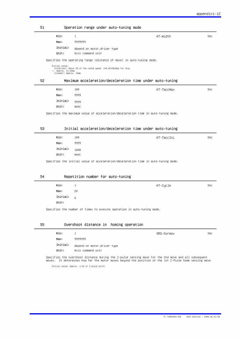
appendix1-12
51 Operation range under auto-tuning mode
Specifies the operating range (distance of move) in auto-tuning mode.
1
9999999
depend on motor.driver type
Min:
Max:
Initial:
Unit: Axis command unit
Initial value: [rotation]: About 2% of the rated speed 2*0.02*360deg for 2rps -> Approx. 14.4deg [linear]: Approx. 10mm
AT-Width Dec
52 Maximum acceleration/deceleration time under auto-tuning
Specifies the maximum value of acceleration/deceleration time in auto-tuning mode.
100
9999
9999
Min:
Max:
Initial:
Unit: msec
AT-TaccMax Dec
53 Initial acceleration/deceleration time under auto-tuning
Specifies the initial value of acceleration/deceleration time in auto-tuning mode.
100
9999
1000
Min:
Max:
Initial:
Unit: msec
AT-TaccIni Dec
54 Repetition number for auto-tuning
Specifies the number of times to execute operation in auto-tuning mode.
1
20
6
Min:
Max:
Initial:
Unit:
AT-Cycle Dec
55 Overshoot distance in homing operation
Specifies the overshoot distance during the Z-pulse sensing move for the 2nd move and all subsequent moves. It determines how far the motor moves beyond the position of the 1st Z-Pulse home sensing move
1
9999999
depend on motor.driver type
Min:
Max:
Initial:
Unit: Axis command unit
Initial value: Approx. 1/16 of Z-pulse pitch
ORG-Ovrmov Dec
TI 71M01D03-01E 10th Edition : 2006.06.01-00
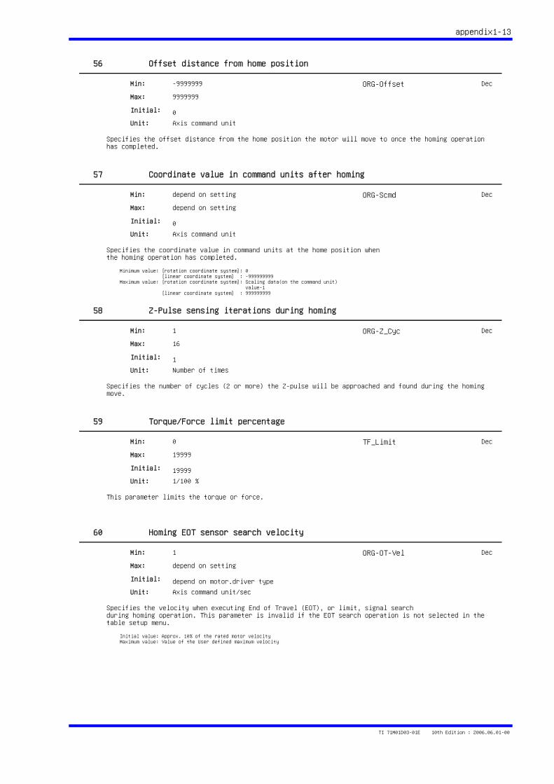
appendix1-13
56 Offset distance from home position
Specifies the offset distance from the home position the motor will move to once the homing operation has completed.
-9999999
9999999
0
Min:
Max:
Initial:
Unit: Axis command unit
ORG-Offset Dec
57 Coordinate value in command units after homing
Specifies the coordinate value in command units at the home position whenthe homing operation has completed.
depend on setting
depend on setting
0
Min:
Max:
Initial:
Unit: Axis command unit
Minimum value: [rotation coordinate system]: 0 [linear coordinate system] : -999999999Maximum value: [rotation coordinate system]: Scaling data(on the command unit) value-1 [linear coordinate system] : 999999999
ORG-Scmd Dec
58 Z-Pulse sensing iterations during homing
Specifies the number of cycles (2 or more) the Z-pulse will be approached and found during the homing move.
1
16
1
Min:
Max:
Initial:
Unit: Number of times
ORG-Z_Cyc Dec
59 Torque/Force limit percentage
This parameter limits the torque or force.
0
19999
19999
Min:
Max:
Initial:
Unit: 1/100 %
TF_Limit Dec
60 Homing EOT sensor search velocity
Specifies the velocity when executing End of Travel (EOT), or limit, signal searchduring homing operation. This parameter is invalid if the EOT search operation is not selected in the table setup menu.
1
depend on setting
depend on motor.driver type
Min:
Max:
Initial:
Unit: Axis command unit/sec
Initial value: Approx. 10% of the rated motor velocityMaximum value: Value of the User defined maximum velocity
ORG-OT-Vel Dec
TI 71M01D03-01E 10th Edition : 2006.06.01-00
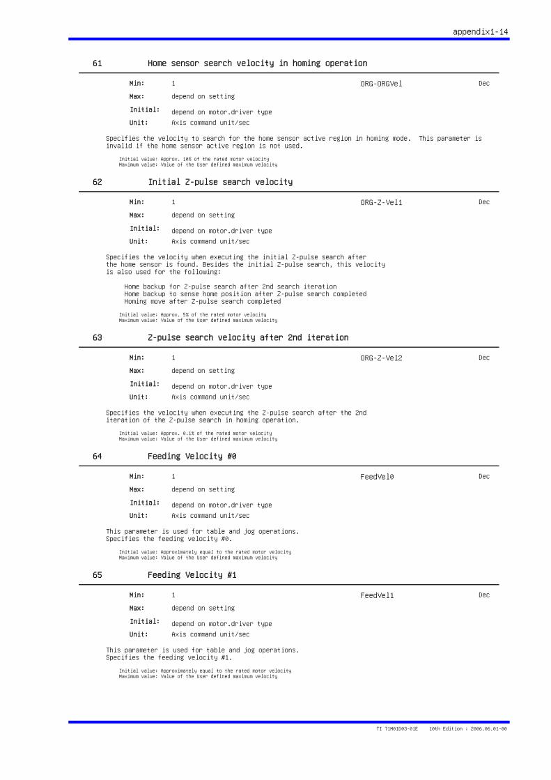
appendix1-14
61 Home sensor search velocity in homing operation
Specifies the velocity to search for the home sensor active region in homing mode. This parameter is invalid if the home sensor active region is not used.
1
depend on setting
depend on motor.driver type
Min:
Max:
Initial:
Unit: Axis command unit/sec
Initial value: Approx. 10% of the rated motor velocityMaximum value: Value of the User defined maximum velocity
ORG-ORGVel Dec
62 Initial Z-pulse search velocity
Specifies the velocity when executing the initial Z-pulse search afterthe home sensor is found. Besides the initial Z-pulse search, this velocityis also used for the following:
Home backup for Z-pulse search after 2nd search iteration Home backup to sense home position after Z-pulse search completed Homing move after Z-pulse search completed
1
depend on setting
depend on motor.driver type
Min:
Max:
Initial:
Unit: Axis command unit/sec
Initial value: Approx. 5% of the rated motor velocityMaximum value: Value of the User defined maximum velocity
ORG-Z-Vel1 Dec
63 Z-pulse search velocity after 2nd iteration
Specifies the velocity when executing the Z-pulse search after the 2nditeration of the Z-pulse search in homing operation.
1
depend on setting
depend on motor.driver type
Min:
Max:
Initial:
Unit: Axis command unit/sec
Initial value: Approx. 0.1% of the rated motor velocityMaximum value: Value of the User defined maximum velocity
ORG-Z-Vel2 Dec
64 Feeding Velocity #0
This parameter is used for table and jog operations.Specifies the feeding velocity #0.
1
depend on setting
depend on motor.driver type
Min:
Max:
Initial:
Unit: Axis command unit/sec
Initial value: Approximately equal to the rated motor velocityMaximum value: Value of the User defined maximum velocity
FeedVel0 Dec
65 Feeding Velocity #1
This parameter is used for table and jog operations.Specifies the feeding velocity #1.
1
depend on setting
depend on motor.driver type
Min:
Max:
Initial:
Unit: Axis command unit/sec
Initial value: Approximately equal to the rated motor velocityMaximum value: Value of the User defined maximum velocity
FeedVel1 Dec
TI 71M01D03-01E 10th Edition : 2006.06.01-00
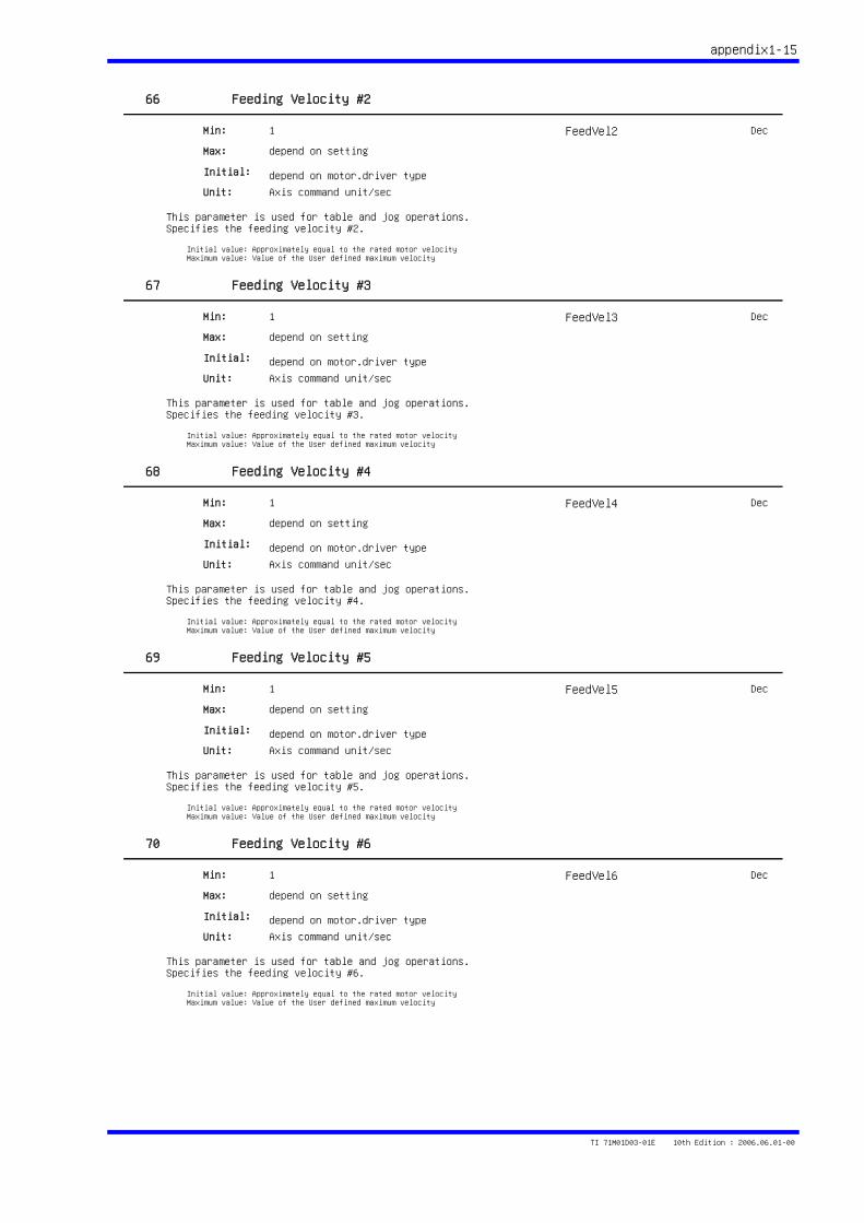
appendix1-15
66 Feeding Velocity #2
This parameter is used for table and jog operations.Specifies the feeding velocity #2.
1
depend on setting
depend on motor.driver type
Min:
Max:
Initial:
Unit: Axis command unit/sec
Initial value: Approximately equal to the rated motor velocityMaximum value: Value of the User defined maximum velocity
FeedVel2 Dec
67 Feeding Velocity #3
This parameter is used for table and jog operations.Specifies the feeding velocity #3.
1
depend on setting
depend on motor.driver type
Min:
Max:
Initial:
Unit: Axis command unit/sec
Initial value: Approximately equal to the rated motor velocityMaximum value: Value of the User defined maximum velocity
FeedVel3 Dec
68 Feeding Velocity #4
This parameter is used for table and jog operations.Specifies the feeding velocity #4.
1
depend on setting
depend on motor.driver type
Min:
Max:
Initial:
Unit: Axis command unit/sec
Initial value: Approximately equal to the rated motor velocityMaximum value: Value of the User defined maximum velocity
FeedVel4 Dec
69 Feeding Velocity #5
This parameter is used for table and jog operations.Specifies the feeding velocity #5.
1
depend on setting
depend on motor.driver type
Min:
Max:
Initial:
Unit: Axis command unit/sec
Initial value: Approximately equal to the rated motor velocityMaximum value: Value of the User defined maximum velocity
FeedVel5 Dec
70 Feeding Velocity #6
This parameter is used for table and jog operations.Specifies the feeding velocity #6.
1
depend on setting
depend on motor.driver type
Min:
Max:
Initial:
Unit: Axis command unit/sec
Initial value: Approximately equal to the rated motor velocityMaximum value: Value of the User defined maximum velocity
FeedVel6 Dec
TI 71M01D03-01E 10th Edition : 2006.06.01-00
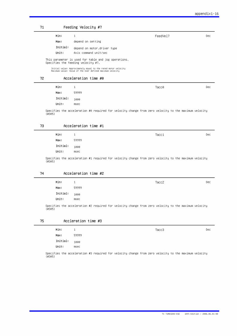
appendix1-16
71 Feeding Velocity #7
This parameter is used for table and jog operations.Specifies the feeding velocity #7.
1
depend on setting
depend on motor.driver type
Min:
Max:
Initial:
Unit: Axis command unit/sec
Initial value: Approximately equal to the rated motor velocityMaximum value: Value of the User defined maximum velocity
FeedVel7 Dec
72 Acceleration time #0
Specifies the acceleration #0 required for velocity change from zero velocity to the maximum velocity (#305)
1
59999
1000
Min:
Max:
Initial:
Unit: msec
Tacc0 Dec
73 Acceleration time #1
Specifies the acceleration #1 required for velocity change from zero velocity to the maximum velocity (#305)
1
59999
1000
Min:
Max:
Initial:
Unit: msec
Tacc1 Dec
74 Acceleration time #2
Specifies the acceleration #2 required for velocity change from zero velocity to the maximum velocity (#305)
1
59999
1000
Min:
Max:
Initial:
Unit: msec
Tacc2 Dec
75 Accleration time #3
Specifies the acceleration #3 required for velocity change from zero velocity to the maximum velocity (#305)
1
59999
1000
Min:
Max:
Initial:
Unit: msec
Tacc3 Dec
TI 71M01D03-01E 10th Edition : 2006.06.01-00
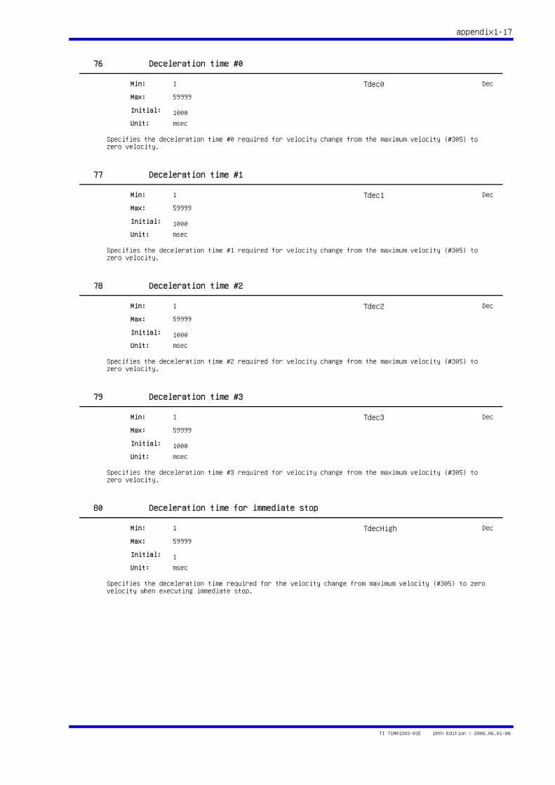
appendix1-17
76 Deceleration time #0
Specifies the deceleration time #0 required for velocity change from the maximum velocity (#305) to zero velocity.
1
59999
1000
Min:
Max:
Initial:
Unit: msec
Tdec0 Dec
77 Deceleration time #1
Specifies the deceleration time #1 required for velocity change from the maximum velocity (#305) to zero velocity.
1
59999
1000
Min:
Max:
Initial:
Unit: msec
Tdec1 Dec
78 Deceleration time #2
Specifies the deceleration time #2 required for velocity change from the maximum velocity (#305) to zero velocity.
1
59999
1000
Min:
Max:
Initial:
Unit: msec
Tdec2 Dec
79 Deceleration time #3
Specifies the deceleration time #3 required for velocity change from the maximum velocity (#305) to zero velocity.
1
59999
1000
Min:
Max:
Initial:
Unit: msec
Tdec3 Dec
80 Deceleration time for immediate stop
Specifies the deceleration time required for the velocity change from maximum velocity (#305) to zero velocity when executing immediate stop.
1
59999
1
Min:
Max:
Initial:
Unit: msec
TdecHigh Dec
TI 71M01D03-01E 10th Edition : 2006.06.01-00
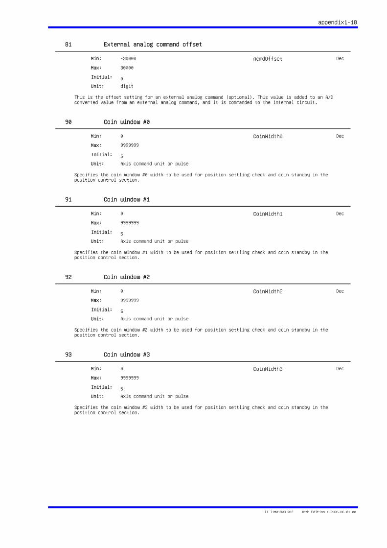
appendix1-18
81 External analog command offset
This is the offset setting for an external analog command (optional). This value is added to an A/D converted value from an external analog command, and it is commanded to the internal circuit.
-30000
30000
0
Min:
Max:
Initial:
Unit: digit
AcmdOffset Dec
90 Coin window #0
Specifies the coin window #0 width to be used for position settling check and coin standby in the position control section.
0
9999999
5
Min:
Max:
Initial:
Unit: Axis command unit or pulse
CoinWidth0 Dec
91 Coin window #1
Specifies the coin window #1 width to be used for position settling check and coin standby in the position control section.
0
9999999
5
Min:
Max:
Initial:
Unit: Axis command unit or pulse
CoinWidth1 Dec
92 Coin window #2
Specifies the coin window #2 width to be used for position settling check and coin standby in the position control section.
0
9999999
5
Min:
Max:
Initial:
Unit: Axis command unit or pulse
CoinWidth2 Dec
93 Coin window #3
Specifies the coin window #3 width to be used for position settling check and coin standby in the position control section.
0
9999999
5
Min:
Max:
Initial:
Unit: Axis command unit or pulse
CoinWidth3 Dec
TI 71M01D03-01E 10th Edition : 2006.06.01-00
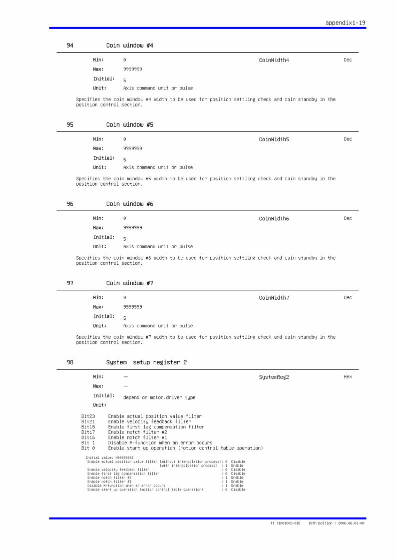
appendix1-19
94 Coin window #4
Specifies the coin window #4 width to be used for position settling check and coin standby in the position control section.
0
9999999
5
Min:
Max:
Initial:
Unit: Axis command unit or pulse
CoinWidth4 Dec
95 Coin window #5
Specifies the coin window #5 width to be used for position settling check and coin standby in the position control section.
0
9999999
5
Min:
Max:
Initial:
Unit: Axis command unit or pulse
CoinWidth5 Dec
96 Coin window #6
Specifies the coin window #6 width to be used for position settling check and coin standby in the position control section.
0
9999999
5
Min:
Max:
Initial:
Unit: Axis command unit or pulse
CoinWidth6 Dec
97 Coin window #7
Specifies the coin window #7 width to be used for position settling check and coin standby in the position control section.
0
9999999
5
Min:
Max:
Initial:
Unit: Axis command unit or pulse
CoinWidth7 Dec
98 System setup register 2
Bit23 Enable actual position value filter Bit21 Enable velocity feedback filter Bit18 Enable first lag compensation filter Bit17 Enable notch filter #2 Bit16 Enable notch filter #1 Bit 1 Disable M-function when an error occurs Bit 0 Enable start up operation (motion control table operation)
-
-
depend on motor.driver type
Min:
Max:
Initial:
Unit:
Initial value: H00030002 Enable actual position value filter [without interpolation process]: 0 Disable [with interpoloation process] : 1 Enable Enable velocity feedback filter : 0 Disable Enable first lag compensation filter : 0 Disable Enable notch filter #2 : 1 Enable Enable notch filter #1 : 1 Enable Disable M-function when an error occurs : 1 Enable Enable start up operation (motion control table operation) : 0 Disable
SystemReg2 Hex
TI 71M01D03-01E 10th Edition : 2006.06.01-00
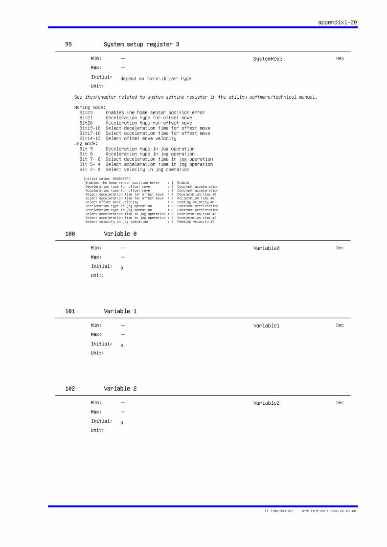
appendix1-20
99 System setup register 3
See item/chapter related to system setting register in the utility software/technical manual.
Homing mode: Bit23 Enables the home sensor position error Bit21 Deceleration type for offset move Bit20 Acceleration type for offset move Bit19-18 Select deceleration time for offest move Bit17-16 Select acceleration time for offest move Bit14-12 Select offset move velocityJog mode: Bit 9 Deceleration type in jog operation Bit 8 Acceleration type in jog operation Bit 7- 6 Select deceleration time in jog operation Bit 5- 4 Select acceleration time in jog operation Bit 2- 0 Select velocity in jog operation
-
-
depend on motor.driver type
Min:
Max:
Initial:
Unit:
Initial value: H008000F7 Enables the home sensor position error : 1 Enable Deceleration type for offset move : 0 Constant acceleration Acceleration type for offset move : 0 Constant acceleration Select deceleration time for offest move : 0 Deceleration time #0 Select acceleration time for offest move : 0 Accleration time #0 Select offset move velocity : 0 Feeding velocity #0 Deceleration type in jog operation : 0 Constant acceleration Acceleration type in jog operation : 0 Constant acceleration Select deceleration time in jog operation : 3 Deceleration time #3 Select acceleration time in jog operation : 3 Acceleration time #3 Select velocity in jog operation : 7 Feeding velocity #7
SystemReg3 Hex
100 Variable 0
-
-
0
Min:
Max:
Initial:
Unit:
Variable0 Dec
101 Variable 1
-
-
0
Min:
Max:
Initial:
Unit:
Variable1 Dec
102 Variable 2
-
-
0
Min:
Max:
Initial:
Unit:
Variable2 Dec
TI 71M01D03-01E 10th Edition : 2006.06.01-00
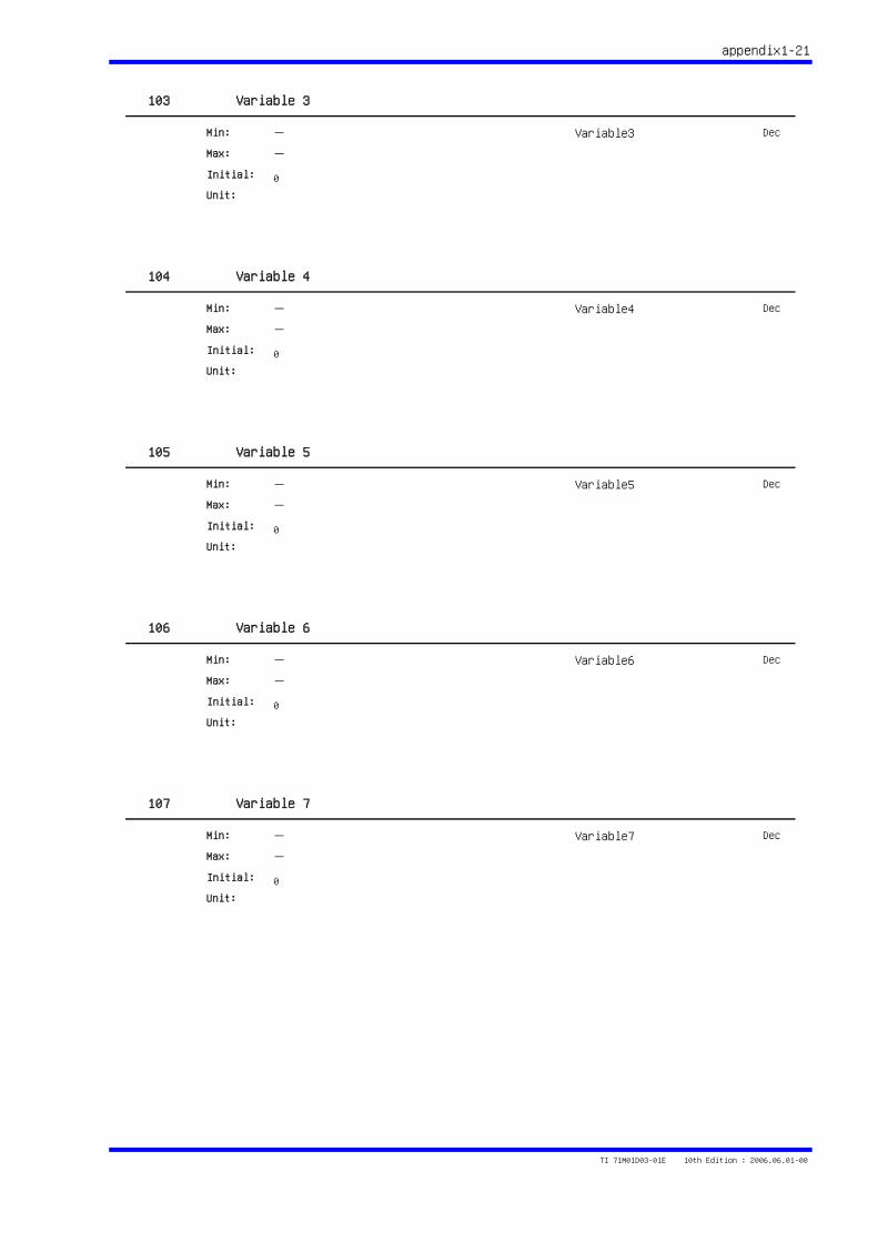
appendix1-21
103 Variable 3
-
-
0
Min:
Max:
Initial:
Unit:
Variable3 Dec
104 Variable 4
-
-
0
Min:
Max:
Initial:
Unit:
Variable4 Dec
105 Variable 5
-
-
0
Min:
Max:
Initial:
Unit:
Variable5 Dec
106 Variable 6
-
-
0
Min:
Max:
Initial:
Unit:
Variable6 Dec
107 Variable 7
-
-
0
Min:
Max:
Initial:
Unit:
Variable7 Dec
TI 71M01D03-01E 10th Edition : 2006.06.01-00

appendix1-22
108 Variable 8
-
-
0
Min:
Max:
Initial:
Unit:
Variable8 Dec
109 Variable 9
-
-
0
Min:
Max:
Initial:
Unit:
Variable9 Dec
TI 71M01D03-01E 10th Edition : 2006.06.01-00
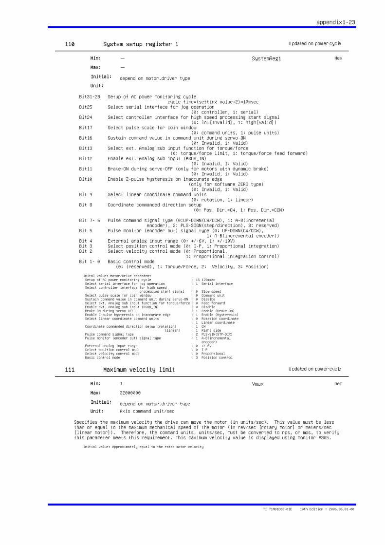
appendix1-23
110 System setup register 1
Bit31-28 Setup of AC power monitoring cycle cycle time=(setting value+2)*10msec Bit25 Select serial interface for jog operation (0: controller, 1: serial) Bit24 Select controller interface for high speed processing start signal (0: low[Invalid], 1: high[Valid]) Bit17 Select pulse scale for coin window (0: command units, 1: pulse units) Bit16 Sustain command value in command unit during servo-ON (0: Invalid, 1: Valid) Bit13 Select ext. Analog sub input function for torque/force (0: torque/force limit, 1: torque/force feed forward) Bit12 Enable ext. Analog sub input (ASUB_IN) (0: Invalid, 1: Valid) Bit11 Brake-ON during servo-OFF (only for motors with dynamic brake) (0: Invalid, 1: Valid) Bit10 Enable Z-pulse hysteresis on inaccurate edge (only for software ZERO type) (0: Invalid, 1: Valid) Bit 9 Select linear coordinate command units (0: rotation, 1: linear) Bit 8 Coordinate commanded direction setup (0: Pos. Dir.=CW, 1: Pos. Dir.=CCW)
Bit 7- 6 Pulse command signal type (0:UP-DOWN(CW/CCW), 1: A-B(incremental encoder), 2: PLS-SIGN(step/direction), 3: reserved) Bit 5 Pulse monitor (encoder out) signal type (0: UP-DOWN(CW/CCW), 1: A-B(incremental encoder)) Bit 4 External analog input range (0: +/-6V, 1: +/-10V) Bit 3 Select position control mode (0: I-P, 1: Proportional integration) Bit 2 Select velocity control mode (0: Proportional, 1: Proportional integration control) Bit 1- 0 Basic control mode (0: (reserved), 1: Torque/Force, 2: Velocity, 3: Position)
-
-
depend on motor.driver type
Min:
Max:
Initial:
Unit:
Inital value: Motor/Drive dependent Setup of AC power monitoring cycle : 15 170msec Select serial interface for jog operation : 1 Serial interface Select controller interface for high speed processing start signal : 0 Slow speed Select pulse scale for coin window : 0 Command unit Sustain command value in command unit during servo-ON : 0 Disalbe Select ext. Analog sub input function for torque/force : 0 Feed forward Enable ext. Analog sub input (ASUB_IN) : 0 Disable Brake-ON during servo-OFF : 1 Enable (Brake-ON) Enable Z-pulse hysteresis on inaccurate edge : 1 Enable (Hysteresis) Select linear coordinate command units : 0 Rotation coordinate : 1 Linear coordinate Coordinate commanded direction setup [rotation] : 1 CW [linear] : 1 Right side Pulse command signal type : 2 PLS-SIN(STP-DIR) Pulse monitor (encoder out) signal type : 1 A-B(incremental encoder) External analog input range : 0 +/-6V Select position control mode : 0 I-P Select velocity control mode : 0 Proportional Basic control mode : 3 Position control
SystemReg1
Updated on power cycle
Hex
111 Maximum velocity limit
Specifies the maximum velocity the drive can move the motor (in units/sec). This value must be less than or equal to the maximum mechanical speed of the motor (in rev/sec [rotary motor] or meters/sec [linear motor]). Therefore, the command units, units/sec, must be converted to rps, or mps, to verify this parameter meets this requirement. This maximum velocity value is displayed using monitor #305.
1
32000000
depend on motor.driver type
Min:
Max:
Initial:
Unit: Axis command unit/sec
Initial value: Approximately equal to the rated motor velocity
Vmax
Updated on power cycle
Dec
TI 71M01D03-01E 10th Edition : 2006.06.01-00
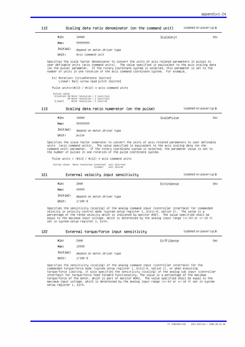
appendix1-24
112 Scaling data ratio denominator (on the command unit)
Specifies the scale factor denominator to convert the units of axis related parameters in pulses to user definable units (axis command units). The value specified is equivalent to the axis scaling data (on the pulse) parameter. If the rotary coordinate system is selected, this parameter is set to the number of units in one rotation of the axis command coordinate system. For example,
Ex) Rotation: Circumference [micron] Linear: Ball screw lead pitch [micron] Pulse units=(#113 / #112) * axis command units
10000
99999999
depend on motor.driver type
Min:
Max:
Initial:
Unit: Axis command unit
Initial value: [rotation] DM Motor resolution / 4 [unit/rev] DR Motor resolution / 2 [unit/rev] [Linear] Motor resolution / 2 [unit/m]
ScaleUnit
Updated on power cycle
Dec
113 Scaling data ratio numerator (on the pulse)
Specifies the scale factor numerator to convert the units of axis related parameters to user definable units (axis command units). The value specified is equivalent to the axis scaling data (on the command unit) parameter. If the rotary coordinate system is selected, the parameter value is set to the number of pulses in one rotation of the pulse coordinate system.
Pulse units = (#113 / #112) * axis command units
10000
99999999
depend on motor.driver type
Min:
Max:
Initial:
Unit: pulse
Initial value: Motor resolution [rotation] unit [pls/rev] [linear] unit [pls/m]
ScalePulse
Updated on power cycle
Dec
121 External velocity input sensitivity
Specifies the sensitivity (scaling) of the analog command input (controller interface) for commanded velocity in velocity control mode (system setup register 1, bits1-0, option 2). The value is a percentage of the rated velocity which is indicated by monitor #307. The value specified shall be equal to the maximum input voltage, which is determined by the analog input range (+/-6V or +/-10 V) set in system setup register 1, bit4.
2000
49999
depend on motor.driver type
Min:
Max:
Initial:
Unit: 1/100 %
ExVinSense
Updated on power cycle
Dec
122 External torque/force input sensitivity
Specifies the sensitivity (scaling) of the analog command input (controller interface) for the commanded torque/force mode (system setup register 1, bits1-0, option 1), or when executing torque/force limiting. It also specifies the sensitivity (scaling) of the analog sub input (controller interface) for torque/force feed forward functionality. The value is a percentage of the maximum torque/force of the motor, which is part of monitor #301. The value specified shall be equal to the maximum input voltage, which is determined by the analog input range (+/-6V or +/-10 V) set in system setup register 1, bit4.
2000
19999
depend on motor.driver type
Min:
Max:
Initial:
Unit: 1/100 %
ExTFiSense
Updated on power cycle
Dec
TI 71M01D03-01E 10th Edition : 2006.06.01-00
Monitor Description STD1
appendix2-1
300 Driver version
Indicates the driver version.
Bit 11- 8 Firmware version code Integer part Bit 7- 4 Firmware version code 1st digit below decimal point Bit 3- 0 Firmware version code 2nd digit below decimal point
Unit: N/A DriverCode Hex
301 Motor specifications
Indicates the motor specifications.
Bit31 Type of motor Bit28-24 Series of motor Bit23 1: Absolute Motor 0: Incremental motor Bit17-16 Voltage Bit15-12 Current Bit11-0 Torque and thrust
Unit: N/A MotorCode Hex
302 Motor resolution
Indicates the motor resolution.
Unit: pulse/rev pulse/m MotorRes Dec
303 Velocity unit conversion coefficient
Indicates the velocity unit conversion coefficient.This monitor value converts from the internal value of the velocity (digits) to [rps] or [mps].
Unit: digit/rps digit/mps VelSense Dec
304 Maximum motor velocity
Indicates the maximum velocity based upon the mechanical limit of the motor/drive combination.
Unit: pulse/sec Vmax[p/s] Dec
305 User defined maximum velocity
This is defined as the smaller value between mechanical limit of the motor/drive combination [converted to axis command unit/sec] and the maximum velocity limit parameter [axis command unit/sec] set in user setting mode. The commanded position velocity is limited by the lesser of the two values. When executing a trapezoidal motion profile (equal acceleration and deceleration ramps) in operation mode, the acceleration/deceleration time depends on the acceleration/deceleration parameters, feed velocity parameter, and the lesser of maximum velocity parameters. A commanded velocity exceeding the mechanical limit of the motor/drive combination is prohibited.
Unit: Axis command unit/sec Vmax Dec
TI 71M01D03-01E 10th Edition : 2006.06.01-00
appendix2-2
306 Z-pulse interval
Indicates the number of encoder pulses contained within one Z-pulse width.
Unit: pulse ZeroPitch Dec
307 Rated velocity
Indicates the rated velocity defined by motor and drive.
Unit: Axis command unit/sec Vrate Dec
310 Physical (Onboard) input blocks 3..0
Indicates the status of physical (onboard) input blocks 3 - 0 (32 bits).
Unit: N/A PbitIn3-0 Hex
311 Physical (Onboard) input blocks 7..4
Indicates the status of physical (onboard) input blocks 7 - 4 (32 bits).
Unit: N/A PbitIn7-4 Hex
312 Physical (Onboard) output blocks 3..0
Indicates the status of physical (onboard) output blocks 3 - 0 (32 bits).
Unit: N/A PbitOut3-0 Hex
313 Physical (Onboard) output blocks 7..4
Indicates the status of physical (onboard) output blocks 7 - 4 (32 bits).
Unit: N/A PbitOut7-4 Hex
314 Logic (Virtual) input blocks 3..0
Indicates the status of logic (virtual) input blocks 3 - 0 (32 bits).
Unit: N/A LbitIn3-0 Hex
315 Logic (Virtual) input blocks 7..4
Indicates the status of logic (virtual) input blocks 7 - 4 (32 bits).
Unit: N/A LbitIn7-4 Hex
TI 71M01D03-01E 10th Edition : 2006.06.01-00
appendix2-3
316 Logic (Virtual) output blocks 3..0
Indicates the status of logic (virtual) output blocks 3 - 0 (32 bits).
Unit: N/A LbitOut3-0 Hex
317 Logic (Virtual) output blocks 7..4
Indicates the status of logic (virtual) output blocks 7 - 4 (32 bits).
Unit: N/A LbitOut7-4 Hex
320 Status register #1
Bit31-24 Error code (main) Bit23-20 Error code (sub) Bit19 Error present Bit18 Home successful Bit17 In position status Bit16 Coin(no position error) status Bit14 Dwell active Bit13 M function executing Bit12 Drive operation active Bit11 Jog operation active Bit10 Axis operation active Bit 9 Servo ready Bit 8 Driver ready Bit 2 Serial interface select for operation device
Unit: N/A StatusReg1 Hex
321 Status register #2
Bit30 Pos. hardware EOT limit active Bit29 Neg. Hardware EOT limit active Bit28 Home sensor active Bit27 Area signal 1 status Bit26 Area signal 2 status Bit25-24 Velocity % override select Bit22-20 Selected coin window # Bit19 Position control integration active Bit18 Velocity control integration active Bit17 Position control selected (0: 1st side, 1: 2nd side) Bit16 Velocity control selected (0: 1st side, 1: 2nd side) Bit15 Z-pulse status Bit 7 Over speed status Bit 6 Overload status Bit 5 Excessive position error Bit 4 Commanded position pulses overflow Bit 2 Excessive regeneration Bit 1 Excessive AC mains voltage Bit 0 AC mains voltage out of range
Unit: N/A StatusReg2 Hex
322 Status register #3
Bit23-16 Operation pattern code Bit15- 8 M function code Bit 7- 0 Operation table code
Unit: N/A StatusReg3 Hex
TI 71M01D03-01E 10th Edition : 2006.06.01-00
appendix2-4
325 Commanded current value
Indicates the value of the current being commanded. The value is 4096 digits when maximum current is commanded.
Unit: digit Icmd Dec
326 Commanded current limit value
Indicates the value of commanded current in digits, limited by the torque/force function, when the torque/force function is enabled (used). The value is 4096 digits when maximum current is commanded.
Unit: digit IcmdLimit Dec
330 Commanded torque/force value
Indicates the value of the torque/force being commanded. The value for the maximum torque/force of the monitor is at 8192 digits.
Unit: digit TFcmdF Dec
331 Pre-filtering commanded torque/force value
Indicates the the value of the torque/force being commanded before using phase delay compensation or notch filter. The value becomes equal to maximum torque/force at 8192 digits.
Unit: digit TFcmd Dec
333 Commanded acceleration feed forward value
Indicates the commanded accleration feed forward value.
Unit: digit Aff Dec
340 Commanded velocity value
Indicates the velocity command value. Number in digits is converted to [rps] or [mps] by dividing by the Velocity unit conversion coefficient monitor value.
Unit: digit Vcmd Dec
341 Commanded post-filtering velocity command value
Indicates the commanded velocity value after velocity command filter processing. Number in digits is converted to [rps] or [mps] by dividing by the Velocity unit conversion coefficient (#303).
Unit: digit VcmdF Dec
342 Actual velocity value
Indicates the actual velocity value. Number in digits is converted to [rps] or [mps] by dividing by the Velocity unit conversion coefficient monitor value(#303).
Unit: digit Vfb Dec
TI 71M01D03-01E 10th Edition : 2006.06.01-00
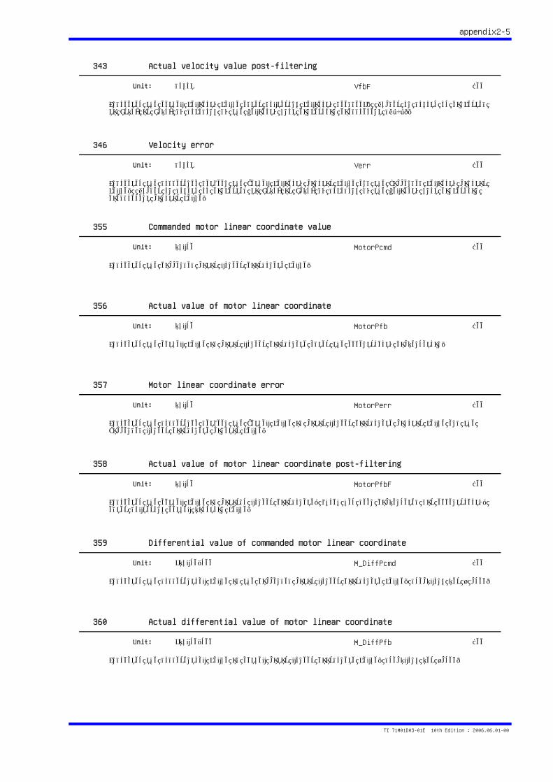
appendix2-5
343 Actual velocity value post-filtering
Indicates the actual velocity value after filtering velocity feedback. Number in digits is converted to [rps] or [mps] by dividing by the Velocity unit conversion coefficient (#303).
Unit: digit VfbF Dec
346 Velocity error
Indicates the difference between the Actual velocity monitor value and the Commanded velocity monitor value. Number in digits is converted to [rps] or [mps] by dividing by the Velocity unit conversion coefficient monitor value.
Unit: digit Verr Dec
355 Commanded motor linear coordinate value
Indicates the commanded motor linear coordinate value.
Unit: pulse MotorPcmd Dec
356 Actual value of motor linear coordinate
Indicates the actual value of motor linear coordinate after the eccentricity compensation.
Unit: pulse MotorPfb Dec
357 Motor linear coordinate error
Indicates the difference between the Actual value of motor linear coordinate monitor value and the Commanded linear coordinate monitor value.
Unit: pulse MotorPerr Dec
358 Actual value of motor linear coordinate post-filtering
Indicates the actual value of motor's linear coordinate, which has been compensated for eccentricity, after filtering actual position value.
Unit: pulse MotorPfbF Dec
359 Differential value of commanded motor linear coordinate
Indicates the differential value of the commanded motor linear coordinate value. (sampling per 1 msec)
Unit: kpulse/sec M_DiffPcmd Dec
360 Actual differential value of motor linear coordinate
Indicates the differential value of actual motor linear coordinate value. (sampling per 1msec)
Unit: kpulse/sec M_DiffPfb Dec
TI 71M01D03-01E 10th Edition : 2006.06.01-00
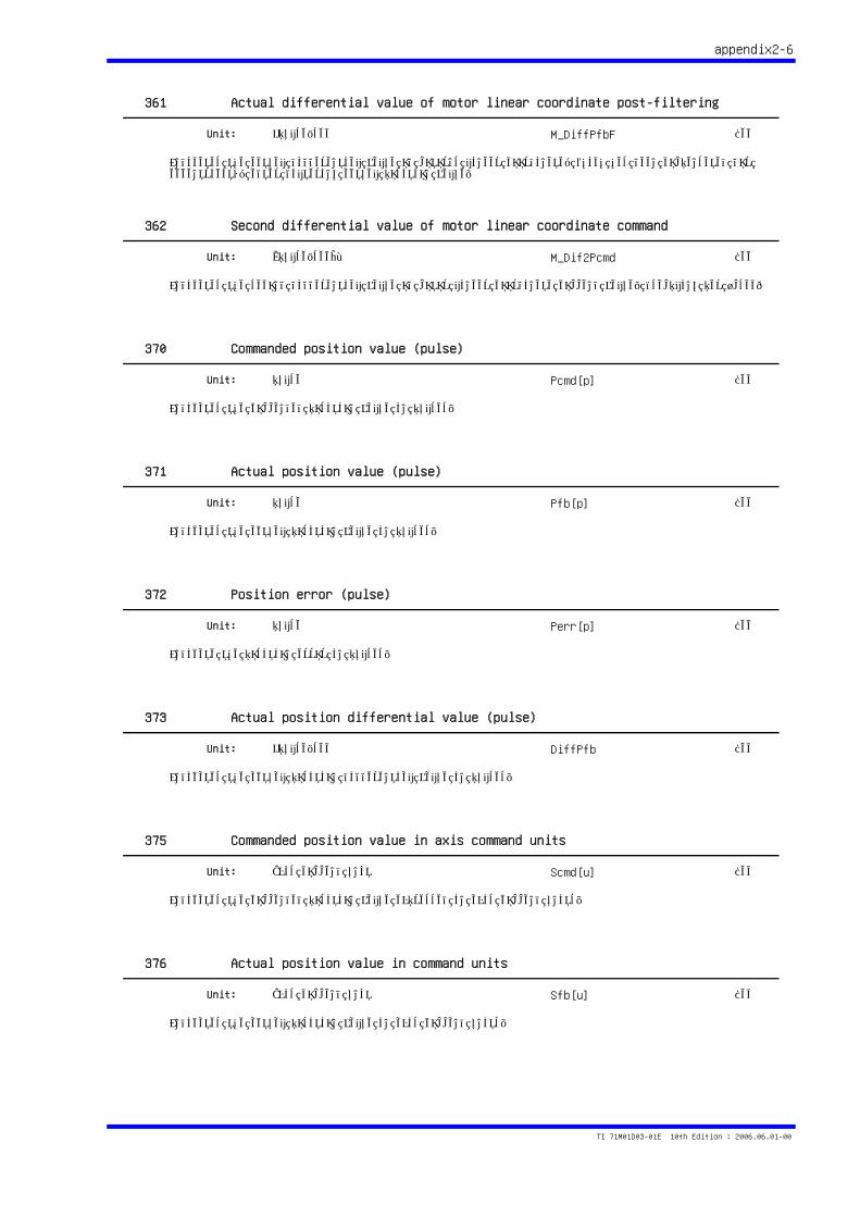
appendix2-6
361 Actual differential value of motor linear coordinate post-filtering
Indicates the actual differential value of motor's linear coordinate, which has been compensated for eccentricity, after filtering actual position value.
Unit: kpulse/sec M_DiffPfbF Dec
362 Second differential value of motor linear coordinate command
Indicates the second differential value of motor linear coordinate command value. (sampling per 1msec)
Unit: Mpulse/sec^2 M_Dif2Pcmd Dec
370 Commanded position value (pulse)
Indicates the commanded position value in pulses.
Unit: pulse Pcmd[p] Dec
371 Actual position value (pulse)
Indicates the actual position value in pulses.
Unit: pulse Pfb[p] Dec
372 Position error (pulse)
Indicate the position error in pulses.
Unit: pulse Perr[p] Dec
373 Actual position differential value (pulse)
Indicates the actual position differential value in pulses.
Unit: kpulse/sec DiffPfb Dec
375 Commanded position value in axis command units
Indicates the commanded position value expressed in axis command units.
Unit: Axis command unit Scmd[u] Dec
376 Actual position value in command units
Indicates the actual position value in axis command units.
Unit: Axis command unit Sfb[u] Dec
TI 71M01D03-01E 10th Edition : 2006.06.01-00
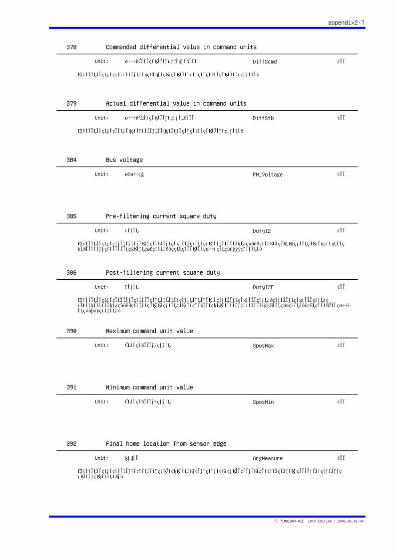
appendix2-7
378 Commanded differential value in command units
Indicates the differential value of commanded in axis command units.
Unit: 1000*Axis command value/sec DiffScmd Dec
379 Actual differential value in command units
Indicates the actual differential value in axis command units.
Unit: 1000*Axis command unit/sec DiffSfb Dec
384 Bus voltage
Unit: 1/100 V PM_Voltage Dec
385 Pre-filtering current square duty
Indicates the instantaneous current square duty (I(superscript: 2)T) before motor heat model filter processing (decimal point 15 bits). It becomes 100% at 32768 digits.
Unit: digit DutyI2 Dec
386 Post-filtering current square duty
Indicates the average (time integrated instantaneous current square duty) current square duty (I(superscript: 2)T) after motor heat model filter processing (decimal point 15 bits). It becomes 100% at 32768 digits.
Unit: digit DutyI2F Dec
390 Maximum command unit value
Unit: Axis command unit SposMax Dec
391 Minimum command unit value
Unit: Axis command unit SposMin Dec
392 Final home location from sensor edge
Indicates the distance between home position and edge of home sensor active region measured during homing operation.
Unit: pulse OrgMeasure Dec
TI 71M01D03-01E 10th Edition : 2006.06.01-00

appendix2-8
393 Test operation monitor
Indicates drive is in test operation.Test operation wave, which is equivalent to the real wave on the oscilloscope, is displayed on the oscilloscope of the utility tool in the support software.
Unit: pulse TstRspns Dec
394 Velocity control proportional gain
Indicates the velocity control proportional gain (decimal point 12 bits).
Unit: digit VelPGain Dec
TI 71M01D03-01E 10th Edition : 2006.06.01-00
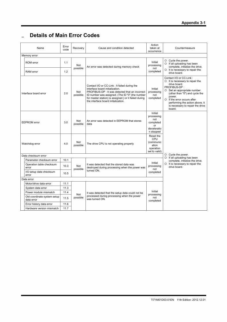
Appendix 3-1
TI71M01D03-01EN 11th Edition: 2012.12.01
Details of Main Error Codes
Name Error code
Recovery Cause and condition detected Action
taken at occurrence
Countermeasure
Memory error
ROM error 1.1 Not
possible An error was detected during memory check
Initial processing
not completed
Cycle the power. If all uploading has been
complete, initialize the drive. It is necessary to repair the
drive board. RAM error 1.2
Interface board error 2.0 Not
possible
Contact I/O or CC-Link : It failed during the interface board initialization. PROFIBUS-DP : It was detected that an incorrect ID number was assigned. (The ID "0" (the number for master station) is assigned.) or it failed during the interface board initialization.
Initial processing
not completed
Contact I/O or CC-Link : It is necessary to repair the
drive board. PROFIBUS-DP : Set an appropriate number
(other than "0") and cycle the power.
If the error occurs after performing the action above, it is necessary to repair the drive board.
EEPROM error 3.0 Not
possible An error was detected in EEPROM that stores data
Initial processing
not completed
or deceleration stopped
Cycle the power. If all uploading has been
complete, initialize the drive. It is necessary to repair the
drive board.
Watchdog error 4.0 Not
possible The drive CPU is not operating properly
Reset the CPU
(communication
operation set to valid)
Data checksum error
Parameter checksum error 10.1
Not possible
It was detected that the stored data was destroyed during processing when the power was turned ON.
Initial processing
not completed
Operation table checksum error
10.3
I/O setup data checksum error
10.5
Data error
Motor/drive data error 11.1
Not possible
It was detected that the setup data could not be processed during processing when the power was turned ON.
Initial processing
not completed
System data error 11.3
Power module mismatch 11.4
Old coordinate system setup data error
11.5
Error history data error 11.6
Hardware version mismatch 11.7
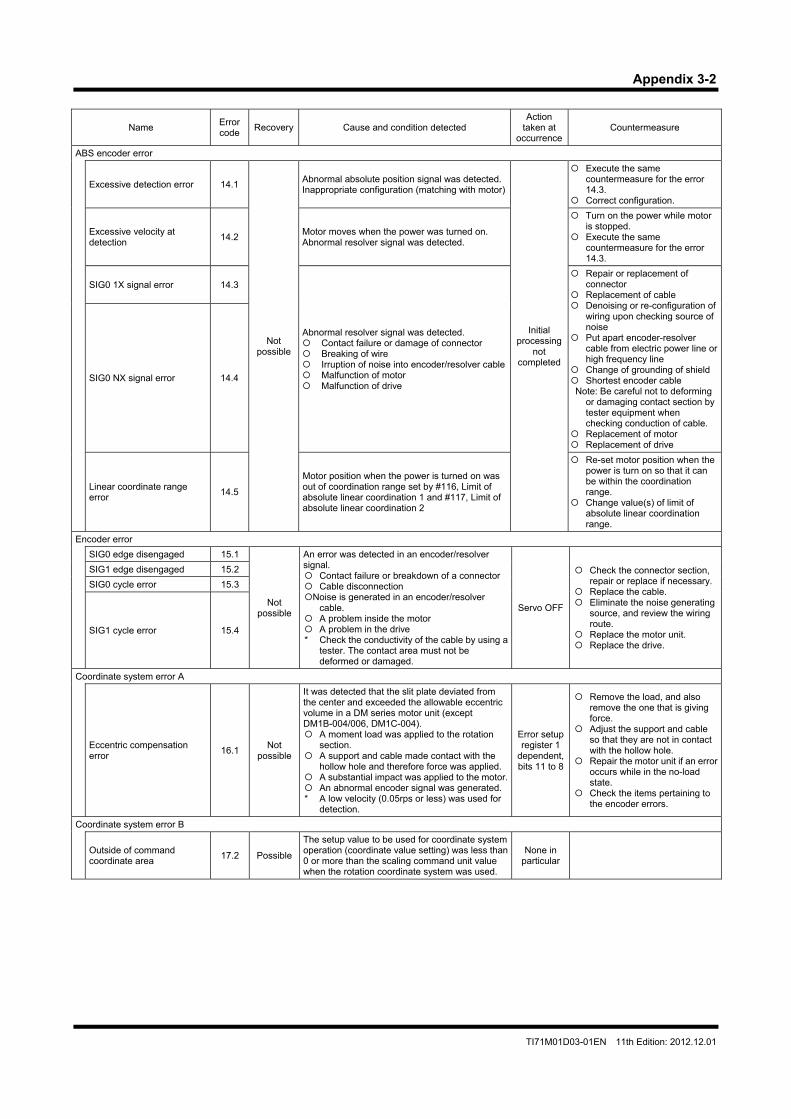
Appendix 3-2
TI71M01D03-01EN 11th Edition: 2012.12.01
Name Error code
Recovery Cause and condition detected Action
taken at occurrence
Countermeasure
ABS encoder error
Excessive detection error 14.1
Not possible
Abnormal absolute position signal was detected.Inappropriate configuration (matching with motor)
Initial processing
not completed
Execute the same countermeasure for the error 14.3.
Correct configuration.
Excessive velocity at detection
14.2Motor moves when the power was turned on. Abnormal resolver signal was detected.
Turn on the power while motor is stopped.
Execute the same countermeasure for the error 14.3.
SIG0 1X signal error 14.3
Abnormal resolver signal was detected. Contact failure or damage of connector Breaking of wire Irruption of noise into encoder/resolver cable Malfunction of motor Malfunction of drive
Repair or replacement of connector
Replacement of cable Denoising or re-configuration of
wiring upon checking source of noise
Put apart encoder-resolver cable from electric power line or high frequency line
Change of grounding of shield Shortest encoder cable Note: Be careful not to deforming
or damaging contact section by tester equipment when checking conduction of cable.
Replacement of motor Replacement of drive
SIG0 NX signal error 14.4
Linear coordinate range error
14.5
Motor position when the power is turned on was out of coordination range set by #116, Limit of absolute linear coordination 1 and #117, Limit of absolute linear coordination 2
Re-set motor position when the power is turn on so that it can be within the coordination range.
Change value(s) of limit of absolute linear coordination range.
Encoder error
SIG0 edge disengaged 15.1
Not possible
An error was detected in an encoder/resolver signal. Contact failure or breakdown of a connector Cable disconnection Noise is generated in an encoder/resolver
cable. A problem inside the motor A problem in the drive * Check the conductivity of the cable by using a
tester. The contact area must not be deformed or damaged.
Servo OFF
Check the connector section, repair or replace if necessary.
Replace the cable. Eliminate the noise generating
source, and review the wiring route.
Replace the motor unit. Replace the drive.
SIG1 edge disengaged 15.2
SIG0 cycle error 15.3
SIG1 cycle error 15.4
Coordinate system error A
Eccentric compensation error
16.1Not
possible
It was detected that the slit plate deviated from the center and exceeded the allowable eccentric volume in a DM series motor unit (except DM1B-004/006, DM1C-004). A moment load was applied to the rotation
section. A support and cable made contact with the
hollow hole and therefore force was applied. A substantial impact was applied to the motor. An abnormal encoder signal was generated.* A low velocity (0.05rps or less) was used for
detection.
Error setup register 1
dependent, bits 11 to 8
Remove the load, and also remove the one that is giving force.
Adjust the support and cable so that they are not in contact with the hollow hole.
Repair the motor unit if an error occurs while in the no-load state.
Check the items pertaining to the encoder errors.
Coordinate system error B
Outside of command coordinate area
17.2 Possible
The setup value to be used for coordinate system operation (coordinate value setting) was less than 0 or more than the scaling command unit value when the rotation coordinate system was used.
None in particular
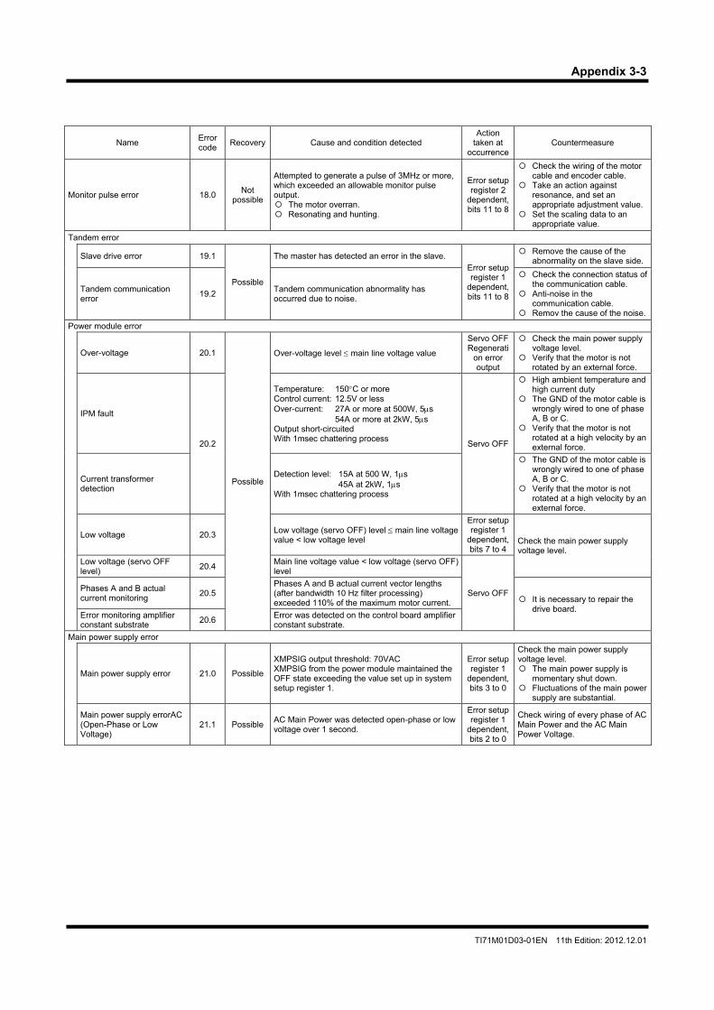
Appendix 3-3
TI71M01D03-01EN 11th Edition: 2012.12.01
Name Error code
Recovery Cause and condition detected Action
taken at occurrence
Countermeasure
Monitor pulse error 18.0Not
possible
Attempted to generate a pulse of 3MHz or more, which exceeded an allowable monitor pulse output. The motor overran. Resonating and hunting.
Error setup register 2
dependent, bits 11 to 8
Check the wiring of the motor cable and encoder cable.
Take an action against resonance, and set an appropriate adjustment value.
Set the scaling data to an appropriate value.
Tandem error
Slave drive error 19.1
Possible
The master has detected an error in the slave. Error setup register 1
dependent, bits 11 to 8
Remove the cause of the abnormality on the slave side.
Tandem communication error
19.2Tandem communication abnormality has occurred due to noise.
Check the connection status of the communication cable.
Anti-noise in the communication cable.
Remov the cause of the noise.
Power module error
Over-voltage 20.1
Possible
Over-voltage level main line voltage value
Servo OFF Regenerati
on error output
Check the main power supply voltage level.
Verify that the motor is not rotated by an external force.
IPM fault
20.2
Temperature: 150C or more Control current: 12.5V or less Over-current: 27A or more at 500W, 5s
54A or more at 2kW, 5s Output short-circuited With 1msec chattering process
Servo OFF
High ambient temperature and high current duty
The GND of the motor cable is wrongly wired to one of phase A, B or C.
Verify that the motor is not rotated at a high velocity by an external force.
Current transformer detection
Detection level: 15A at 500 W, 1s 45A at 2kW, 1s
With 1msec chattering process
The GND of the motor cable is wrongly wired to one of phase A, B or C.
Verify that the motor is not rotated at a high velocity by an external force.
Low voltage 20.3 Low voltage (servo OFF) level main line voltage value < low voltage level
Error setup register 1
dependent, bits 7 to 4
Check the main power supply voltage level.
Low voltage (servo OFF level)
20.4Main line voltage value < low voltage (servo OFF) level
Servo OFF Phases A and B actual current monitoring
20.5Phases A and B actual current vector lengths (after bandwidth 10 Hz filter processing) exceeded 110% of the maximum motor current. It is necessary to repair the
drive board.
Error monitoring amplifier constant substrate
20.6Error was detected on the control board amplifier constant substrate.
Main power supply error
Main power supply error 21.0 Possible
XMPSIG output threshold: 70VAC XMPSIG from the power module maintained the OFF state exceeding the value set up in system setup register 1.
Error setup register 1
dependent, bits 3 to 0
Check the main power supply voltage level. The main power supply is
momentary shut down. Fluctuations of the main power
supply are substantial.
Main power supply errorAC (Open-Phase or Low Voltage)
21.1 Possible AC Main Power was detected open-phase or low voltage over 1 second.
Error setup register 1
dependent, bits 2 to 0
Check wiring of every phase of AC Main Power and the AC Main Power Voltage.
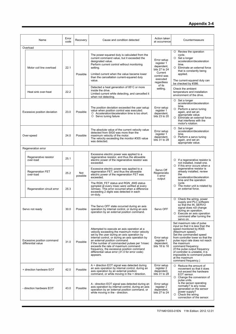
Appendix 3-4
TI71M01D03-01EN 11th Edition: 2012.12.01
Name Error code
Recovery Cause and condition detected Action taken
at occurrence Countermeasure
Overload
Motor coil line overload 22.1
Possible
The power-squared duty is calculated from the current command value, but it exceeded the designated value. Perform current control without monitoring setting. Limited current when the value became lower than the cancellation current-squared duty value.
Error setup register 1
dependent, bits 27 to 24
Current control was executed
regardless of its
setting.
Review the operation cycle.
Set a longer acceleration/deceleration time.
Eliminate an external force that is constantly being applied.
The current-squared duty can be checked by #386.
Heat sink over-heat 22.2
Detected a heat generation of 85C or more inside the drive. Limited current while detecting, and cancelled it when not detecting.
Check the ambient temperature and installation environment of the drive.
Excessive position deviation 23.0 Possible
The position deviation exceeded the user setup value when position control was executed. Acceleration/deceleration time is too short. Servo tuning failure
Error setup register 1
dependent, bits 23 to 20
Set a longer acceleration/deceleration time.
Perform a servo tuning again, and set an appropriate value.
Eliminate an external force that interferes with the motor's rotation.
Over-speed 24.0 Possible
The absolute value of the current velocity value detected from SIG0 was more than the maximum velocity of the motor. The velocity exceeding the monitor #305 value was detected.
Error setup register 1
dependent, bits 31 to 28
Set a longer acceleration/deceleration time.
Perform a servo tuning again, and set an appropriate value.
Regeneration error
Regenerative resistor over-load 25.1
Not possible
Excessive electric power was applied to a regenerative resistor, and thus the allowable electric power of the regenerative resistor was exceeded.
Servo Off Regeneratio
n error output
If a regenerative resistor is not installed, install one.
If this error occurs when a regenerative resistor is already installed, review the acceleration/deceleration time and the operation cycle.
The motor unit is rotated by an external force.
Regeneration FET over-load 25.2
Excessive electric power was applied to a regeneration FET, and thus the allowable electric power of the regeneration FET was exceeded.
Regeneration circuit error 25.3
The RGN_FET status and RGN_ANS status sampled at every msec were verified at every 32msec. This error occurred when a difference exceeding 2 digits was detected in each on-duty.
Servo not ready 30.0 Possible The Servo OFF state occurred during an axis operation by internal control, or during an axis operation by an external position command.
Servo OFF
Check the wiring, power supply and PLC software so that the IN_SERVO signal does not change during an operation.
Execute an axis operation command after turning the servo on.
Excessive position command differential value 31.0 Possible
Attempted to execute an axis operation at a velocity exceeding the maximum motor velocity set by the user during an axis operation by internal control, or during an axis operation by an external position command. If the number of commanded pulses per 1msec exceeds the rate of maximum command frequency, the excessive position command differential value error (31.0 for error code) appears.
Error setup register 1
dependent, bits 18 to 16
Set maximum rate of pulse input so that it is less than the speed monitored by #305 (Maximum speed). Set the commanded speed from controller lower so that the pulse input rate does not reach the maximum command frequency. (If the pulse output frequency of controller is unstable, it is impossible to command pulses at the maximum command frequency.)
+ direction hardware EOT 42.0 Possible
A + direction EOT signal was detected during an axis operation by internal control, during an axis operation by an external position command, or while moving in the + direction.
Error setup register 2
dependent, bits 31 to 28
Reduce the amount of movement so that it does not exceed the hardware EOT sensor.
Change the conversion of pulse units. Is the sensor operating normally? Is any noise generated on the sensor power supply?
Check the wiring connection of the sensor.
- direction hardware EOT 43.0 Possible
A - direction EOT signal was detected during an axis operation by internal control, during an axis operation by an external position command, or while moving in the - direction.
Error setup register 2
dependent, bits 27 to 24
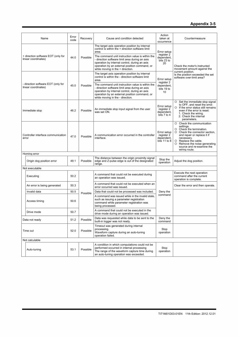
Appendix 3-5
TI71M01D03-01EN 11th Edition: 2012.12.01
Name Error code
Recovery Cause and condition detected Action
taken at occurrence
Countermeasure
+ direction software EOT (only for linear coordinates) 44.0 Possible
The target axis operation position by internal control is within the + direction software limit area. Error setup
register 2 dependent, bits 23 to
20 Check the motor's instructed movement amount against the current position. Is the position exceeded the set software over-limit area?
The command unit instruction value is within the - direction software limit area during an axis operation by internal control, during an axis operation by an external position command, or while moving in the + direction.
- direction software EOT (only for linear coordinates)
45.0 Possible
The target axis operation position by internal control is within the - direction software limit area. Error setup
register 2 dependent, bits 19 to
10
The command unit instruction value is within the - direction software limit area during an axis operation by internal control, during an axis operation by an external position command, or while moving in the - direction.
Immediate stop 46.2 Possible An immediate stop input signal from the user was set ON.
Error setup register 2
dependent, bits 7 to 4
Set the immediate stop signal to OFF, and reset the error.
If the error status still remains even if the error is reset: 1. Check the wiring. 2. Check the internal
parameters.
Controller interface communication error 47.0 Possible A communication error occurred in the controller
interface.
Error setup register 2
dependent, bits 11 to 8
Check the communication settings.
Check the termination. Check the connector section,
and repair or replace it if necessary.
Replace the cable. Remove the noise generating
source and re-examine the wiring route.
Homing error
Origin dog position error 49.1 Possible The distance between the origin proximity signal edge and Z-pulse edge is out of the designated range.
Stop the operation Adjust the dog position.
Not executable
Executing 50.2
Possible
A command that could not be executed during an operation was issued.
Deny the command
Execute the next operation command after the current operation is complete.
An error is being generated 50.3 A command that could not be executed when an error occurred was issued.
Clear the error and then operate.
Invalid data 50.5 Data that could not be processed was included.
Access timing 50.6
A command was issued while in the invalid state, such as issuing a parameter registration command while parameter registration was being processed.
Drive mode 50.7 A command that could not be executed in the drive mode during an operation was issued.
Data not ready 51.2 Possible Data was requested while data to be sent to the built-in logger was not ready.
Deny the command
Time out 52.0 Possible
Timeout was generated during internal processing. Waveform capture during an auto-tuning operation failed.
Stop operation
Not calculable
Auto-tuning 53.1 Possible
A condition in which computations could not be performed occurred in internal processing The range of the waveform capture time during an auto-tuning operation was exceeded.
Stop operation

Appendix 3-6
TI71M01D03-01EN 11th Edition: 2012.12.01
Name Error code
Recovery Cause and condition detected Action
taken at occurrence
Countermeasure
Command translation Invalid 60.0 Possible A command that could not be translated was issued.
Deny the command
Command format error 61.0 Possible A command that did not match the command format was issued.
Out of range data 62.0 Possible A command using data that exceeds the allowable range was issued.
Invalid parameter/monitor number 65.0 Possible A command that specified a parameter/monitor having a non-existent number was issued.
Invalid device 66.0 Possible A command was issued by an interface that did not have an operation privilege.
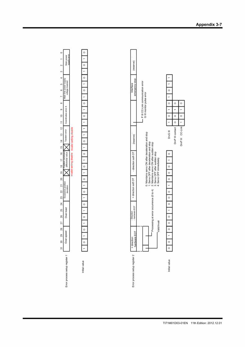
Appendix 3-7
TI71M01D03-01EN 11th Edition: 2012.12.01
31
30
29
28
27
26
25
24
23
22
21
20
19
18
17
16
15
14
13
12
11
10
98
76
54
32
10
(reserve)
(reserve)
11
00
11
00
11
00
11
00
11
00
11
00
11
00
11
01
01
00
01
00
01
00
01
00
11
00
DrvGⅢ
DrvPⅢ
CC-Link
11
00
01
00
11
01
Exc
essi
ve p
ositi
on d
evia
tion
Ove
r-lo
ad
Ove
r-sp
eed
Err
or p
roce
ss s
etup
reg
iste
r 1
Inte
rfa
ce
em
erg
en
cy s
top
+ d
irect
ion
ha
rdw
are
EO
T Pro
cess
ing
at e
rro
r o
ccu
rre
nce
(0
to 4
)
- D
irect
ion
-
hard
war
e E
OT
Pos
ition
com
man
d
diff
eren
tial v
alu
e
Inva
lid s
ett
ing
dis
able
+ d
irect
ion
so
ft O
T-
dire
ctio
n so
ft O
T(r
ese
rve
) E
rror
pro
cess
set
up r
egis
ter
2
Mai
n po
wer
s
uppl
y er
ror
Mai
n lin
e p
ow
er s
upp
ly
vol
tage
low
ered
0:
Ma
inta
ins
serv
o O
N a
fte
r d
ece
lera
tion
and
sto
p1
: S
erv
o O
FF
aft
er
de
cele
ratio
n a
nd s
top
2:
Ma
inta
ins
serv
o O
N a
fte
r su
dde
n s
top
3:
Se
rvo
OF
F a
fte
r su
dde
n s
top
4:
Se
rvo
OF
F im
me
dia
tely
Coo
rdin
ates
err
or A
P I
II C
C-L
ink
com
mun
icat
ion
erro
r G
III
mon
itor
puls
e e
rro r
(re
serv
e)
Initi
al v
alu
e
Initi
al v
alu
eD
rvG
III
Drv
P I
II c
onta
ct
Drv
P I
II C
C-L
ink
Inva
lid s
ett
ing
dis
able
Tan
dem
err
or
Va
lid/In
vali
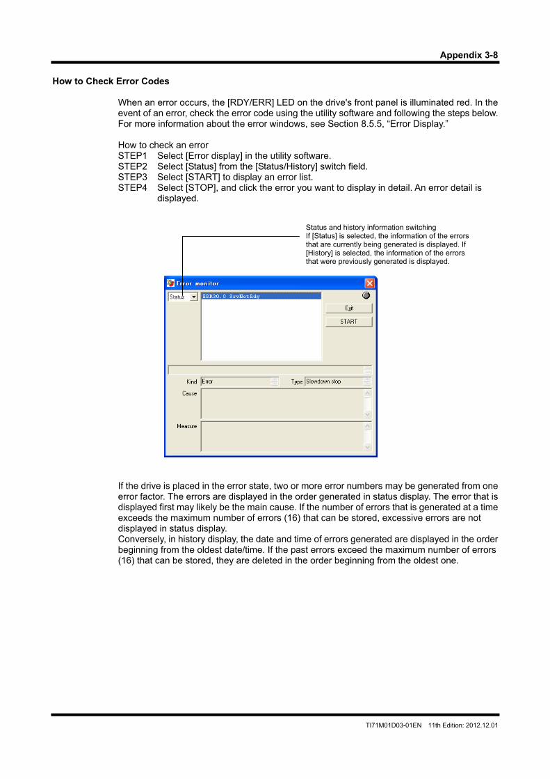
Appendix 3-8
TI71M01D03-01EN 11th Edition: 2012.12.01
How to Check Error Codes
When an error occurs, the [RDY/ERR] LED on the drive's front panel is illuminated red. In the event of an error, check the error code using the utility software and following the steps below. For more information about the error windows, see Section 8.5.5, “Error Display.” How to check an error STEP1 Select [Error display] in the utility software. STEP2 Select [Status] from the [Status/History] switch field. STEP3 Select [START] to display an error list. STEP4 Select [STOP], and click the error you want to display in detail. An error detail is
displayed.
If the drive is placed in the error state, two or more error numbers may be generated from one error factor. The errors are displayed in the order generated in status display. The error that is displayed first may likely be the main cause. If the number of errors that is generated at a time exceeds the maximum number of errors (16) that can be stored, excessive errors are not displayed in status display. Conversely, in history display, the date and time of errors generated are displayed in the order beginning from the oldest date/time. If the past errors exceed the maximum number of errors (16) that can be stored, they are deleted in the order beginning from the oldest one.
Status and history information switching If [Status] is selected, the information of the errors that are currently being generated is displayed. If [History] is selected, the information of the errors that were previously generated is displayed.
Appendix 4-1
TI71M01D03-01EN 11th Edition: 2012.12.01
Glossary
This glossary lists the terms used in this document. Symbols
# Indicates the number of a parameter stored on RAM. Example: #100
##
Indicates the number of a parameter stored on EEPROM. Example: ##100 @
Indicates a command number. Example: @3:10 @Command
A general term for operation commands issued from a PC to the drive. Example: @3:10
A
ABS Absolute position, or a motor built in with an absolute position detector called the ABS motor
Absolute Accuracy
The difference between the angle at which the motor should be rotated (instructed value) and the angle at which the motor actually rotates. This value is displayed after adding a sign to a half of the maximum value for the entire circumference of one rotation.
Absolute Positioning
Operation to position at an absolute coordinate position Alarm
A warning whose level is lower than an error Aliasing
A phenomenon in which waveforms cannot be displayed accurately when the sampling velocity becomes half (Nyquist frequency) or below the input signal. Generally, in order to display accurate waveforms on a digital oscilloscope, a sampling velocity about 4 to 10 times the frequency of the input signal as well as a frequency band at least three times the frequency of the input signal are required.
All Reset
An operation to return all user data to the factory preset values. Analog Monitor Card
A board that is inserted into a connector of the front panel section of the drive and used to monitor the velocity and other information using an oscilloscope (optional).
Analog Monitor Terminal
General-purpose monitor terminals AM1 and AM2 on the analog monitor card Argument
An option to be added to an operation command. Some commands have no argument or have multiple arguments.
Auto Start Table
Set [Auto Start Function] to [Valid] to perform automatic operation after the power is turned ON. By this setting, the table having the number that has been set up starts.
Appendix 4-2
TI71M01D03-01EN 11th Edition: 2012.12.01
Auto Tuning
A series of operations to rotate the motor, measure the load inertia/load mass, and set up the parameters of the control section on its own.
Axial load (Forward, Reverse)
The motor is fastened to the base and a uniform dead load is applied to the rotor's load mounting area in the axial direction. The "axial load" is the maximum load when all component parts of the motor are within the elastic deformation zone. When the load is removed, all the component parts must be restored to their original states. Note that the forward axial load refers to contracting the motor in its axial direction, and the reverse axial load refers to adding a load to the motor in its expansion direction.
Axial stiffness (Forward, Reverse)
This refers to the axial displacement per unit axial load when the motor is fastened to the base and a uniform dead load is added to the rotor's load mounting area in the axial direction within the axial load. "Axial displacement/axial load" must be linear. Forward Axial stiffness refers to contracting the motor in its axial direction, and the reverse Axial stiffness refers to adding a load to the motor in its expansion direction.
AXIS
Motor axis Axis Command Unit
The common unit set up by the #112 parameter
B
Backup Storing data from the drive to an upper device (PC, operation display pendant). Same as upload.
Basic Data
Maker information of the drive/motor, which cannot be manipulated by users. This data cannot be erased by all reset operations.
BCD
Binary coded decimal BIN
Binary Binary Code
A numerical code in binary notation Bit AND
AND for each bit. This is used to extract several bits. Bit EXOR
Exclusive OR for each bit Bit OR
OR for each bit. This is used to turn ON several bits. Block
Logic I/O and physical (hard) I/O are internally managed in 8-bit units, each of which is called a block. I/O settings are also performed in block units.
Branching
To branch. Table operation - condition branching
Appendix 4-3
TI71M01D03-01EN 11th Edition: 2012.12.01
Bus Voltage
Main power supply voltage after rectification
C
CC-Link Open network standard - fieldbus
CCW
Counterclockwise - Counterclockwise direction when the motor is viewed from the load mounting plane
Chattering Processing
In this document, it refers to the processing to give hysteresis for eliminating unnecessary ON/OFF when generating a position settling signal. The number of processing to be performed can be set up using a parameter.
COIN
Coincidence signal (position settling signal) - A signal that is output when the motor is within the coin window that has been set up
Coin Waiting
In motor operation, this refers to a wait until the motor is positioned within the coin window before moving to the next operation upon completion of a position command.
Control Power Supply
A power supply for the control board Current Transformer
A transformer built in the power module for detecting current. It monitors the current of the bus.
CW
Clockwise - Clockwise direction when the motor is viewed from the load mounting plane
D
DEC Decimal
Decimal Code
A numerical code in decimal notation Digit
Unit of calculations used by firmware inside the drive Digital Monitor Terminal
Dedicated digital monitor terminals DM1 and DM2 on the analog monitor card DM series
Motors built in with an optical encoder Download
Writing data from an upper device (PC, operation display pendant) to the drive DR series
Motors built in with a magnetic encoder (resolver)
Appendix 4-4
TI71M01D03-01EN 11th Edition: 2012.12.01
E
EEPROM Nonvolatile memory built in the drive that stores mechanical data and user data. There is a limit on the number of times it can be rewritten.
Encoder Resolution
Number of pulses output from the encoder when the motor makes one rotation. EOT
EOT signal - there are hardware EOT and software EOT. Error
An abnormality whose level is higher that an alarm. Errors are classified by error number. For some errors, the behavior of the motor after an error occurrence can be defined using the error setup register.
F
Filter A function to remove unwanted signal components from signals
Firmware
A program code of the CPU in the drive Function Key
General-purpose keys on the operation display pendant. The functions of these keys change depending on the screen displayed.
G H
Heat Sink Radiating fins on the side of the drive. Equipped only on 2kW drives.
HEX
Hexadecimal Hexadecimal Code
A numerical code in hexadecimal notation Hollow Hole Structure
A motor structure in which a hollow hole is provided in the center of the motor axis so that piping, a wiring, shaft and ball screws can be fed through in the DYNASERV.
Host
An upper device that sends instructions to the drive
I
ID Drive station number set up by the rotary switches on the front panel
Idle State
A state in which no operation is being performed INC
Increment (relative position notation)
Appendix 4-5
TI71M01D03-01EN 11th Edition: 2012.12.01
Increment Positioning
A relative move command from the current position Interlock
The velocity override value is set to 0% internally. Invalid
Invalid state. To not use a specific function in parameter settings, etc., set to invalid (0). IPM fault signal
An error signal output by the IPM unit built in the power module IPM fault signal
An error signal output by the IPM unit built in the power module
J K
kpulse Unit of pulses obtained by raising 10 to the third power
L
Linear Coordinate System A coordinate system that manages coordinates within a range of -999999999 to 999999999 linearly. If this range is exceeded, a software EOT error occurs.
LM series
Linear motors Load Inertia
The moment of inertia of load attached to the motor Load Scale Factor
Load scale factor [K] = load inertia/rotor inertia
Logic I/O A virtual I/O of firmware in the drive. Some of logic I/O are assigned to actual I/O (hard I/O).
Logic I/O Initial Value
Initial values (ON or OFF) at power-on start can be set up for logic I/O (inputs only). Setting initial values to logic I/O actually assigned to hard I/O has no significance as they are initialized to external commands at startup.
M
Machine Resonance Since the DD motor directly drives load, the characteristics of the load may affect the control system, causing oscillations. These oscillations include hunting and windup phenomenon at a relatively low frequency (several Hz), an oscillation around a high frequency phase, and a mechanical oscillation. To take appropriate countermeasures, it is necessary to know the accurate resonance frequency.
Machine Setting Parameter
If these parameters are changed, the changes made take effect when the power is turned ON next time (parameters starting from #110).
Appendix 4-6
TI71M01D03-01EN 11th Edition: 2012.12.01
Main Power
A power supply for operating the motor Maker Data
Internal data set up by Yokogawa. This data cannot be set up by users. It cannot be erased by all reset operation. (Basic data, adjustment data)
Manual Tuning
An operation for adjusting each control parameter by operating the motor via a test operation and then using an oscilloscope and the utility software functions.
Master
Indicates the master motor/drive in a master and slave relation in tandem operation. Maximum Output Torque
The motor's output torque when driving at the drive's maximum output current. The maximum output torque is generated at startup (the velocity is zero) in the case of DD motors.
Maximum overhung load
The motor is fastened to the base and a moment dead load is applied to the rotor's load mounting area in the direction where the rotor's rotation axis core is tilted. The "maximum overhung load" is the maximum load when all component parts of the motor are within the elastic deformation zone. When the load is removed, all the component parts must be restored to their original states. In addition, the gap between the rotor and the stator core must not be zero (the core makes contact) in the worst condition.
Maximum Velocity
The maximum velocity a motor can rotate. Moment displacement stiffness
The motor is fastened to the base and a moment dead load is applied to the rotor's load mounting area in the direction where the rotor's rotation axis core is tilted within the maximum overhung load. Moment displacement stiffness is the axis core tilt displacement angle per unit moment load at this time. "Displacement angle/moment load" must be linear.
Monitor Pulse
Current position value pulse output from the drive Motorless Operation (Emulation Mode)
A mode for simulating the operations of the motor using only the drive without connecting the actual motor. This feature is convenient to check general operations of the motor before starting the system. The utility software is used for simulation.
Mpulse
Unit of pulses obtained by raising 10 to the sixth power Multichannel Connection
A connection to connect multiple drives to a party line using RS485 communication. A dedicated DLL is required for control from a PC.
N
O
Operation Display Panel A separately sold device that is connected to the drive, which displays/edits parameters and issues commands.
Appendix 4-7
TI71M01D03-01EN 11th Edition: 2012.12.01
Operation Display Pendant
A separately sold device that is connected to the drive, which displays/edits parameters and issues commands. It has the backup/restore function.
Operation Privilege
A right to issue major commands. Available on the PLC interface side or RS232C interface side.
ORG
Origin proximity signal Outer Rotor Mechanism
A mechanism that rotates the outer part of the motor. A load can be installed directly.
P
Parameter Reflected at Power On See Machine Setting Parameter.
Parameter Setting Value
Generally, parameter values set up on the drive's internal RAM (example: #100). The operation of the drive is determined based on these parameter values.
Physical (Hard) I/O
I/O actually mounted to the drive (physical I/O) Physical (Hard) I/O Logical Setting
Setting regarding whether I/O input/output is positive logic (internally ON when a I/O is ON) or negative logic (internally OFF when a I/O is OFF)
PLC
Programmable logic controller, generally called the sequencer. Yokogawa offers the FA-M3 range free controller.
Position Command Differential Value
Difference among position command values per sampling cycle (1msec) Product Dependency
The initial value of a parameter takes a different value according to the type of the motor/drive.
Prompt
A character string, parameter name, error name and so forth included in a response from the drive when a communication is made with the drive using the utility software, display panel, etc.
Pulse Direct
A weighted signal of an external pulse. If this signal is ON, the motor operates one pulse of motor resolution by an external one pulse command, ignoring the scale setting.
R
Reboot Restarting the drive by cycling the power or using a software reset command.
Registered Parameter Value
Parameter values stored on the drive's internal EEPROM (example: ##100). The drive loads these values as parameter setup values at startup. If these parameter values are changed, the parameter setup values are also changed at the same time.
Appendix 4-8
TI71M01D03-01EN 11th Edition: 2012.12.01
Repeatability Accuracy
Positioning is repeated seven times from the same rotation direction. This value is displayed after adding a sign to a half of the maximum width value of variations of the seven positions.
Restore
Writing backed up data from an upper device (PC, operation display pendant) to the drive. Same as download.
Rotation Coordinate System
A coordinate system in which the coordinate values after one motor rotation becomes equal to the coordinate values before movement. The coordinate system does not overflow even if the motor is continuously rotated in the same direction.
Rotor Core
A magnetic circuit provided in the motor's rotating part Rotor Inertia
Inertial moment around the rotor's rotation axis of the motor. Self-inertia. RxD
Receive signal during host communication S
Scaling Scale factors specified by the #112 and 113 parameters, which are used for conversion between pulse units and command units.
Settling Time
A delay occurs in the actual motion of the motor in response to a position command. Upon executing a position command, the difference in time until a settling signal is output is specifically called the settling time.
Setup Dependency
The allowable setup range of the maximum and minimum values of a parameter changes according to the setup values of other parameters
SIG0 and SIG1 signals
Analog velocity signals generated by an encoder signal Skew
Variations in the phases among signals Slave
It refers to the driven motor/drive in a master and slave relation in tandem operation. Software Drive Reset
Restarting the drive by a command issued by the utility software, operation display panel/pendant, etc. This function is equivalent to cycling of the power.
Start Option
Command arguments Startup Operation
Table operation executed automatically when the power is turned ON according to settings.
Appendix 4-9
TI71M01D03-01EN 11th Edition: 2012.12.01
Station Number
A drive number set up by the rotary switches on the front panel section when connecting multichannels.
Stator Core
A magnetic circuit provided in the motor fastening section Status Register
#320, 321 and 322 monitors. They constantly display the status of the motor/drive. Just like the system registers, each bit is assigned with a unique definition.
Sum Value
Firmware and data embedded in the drive are managed using sum values. System Register
#98, 99 and 110 parameters. These parameters set up the drive's main operations. The system register parameters are 32-bit wide data, and each bit is assigned with a unique definition.
T
Table Data Operation command data contained within the drive, total of 64
Tandem Operation
An operation method for obtaining large torque and thrust by connecting multiple motors and drives using a multi-drop connection
Tuning
An operation for adjusting each servo parameter to an appropriate value. This drive is installed with the auto tuning function by which tuning is performed automatically.
TxD
Transmit signal during host communication
U
Unit Unit refers to a command unit in this document.
Upload
Moving data from the drive to an upper device (PC, operation display pendant) User Data
Internal data, such as parameters, table data and I/O setup values, which can be rewritten using the utility software/operation display pendant, etc.
V
Valid Permitted state. To use a function by setting its parameters and other items, set to valid (1).
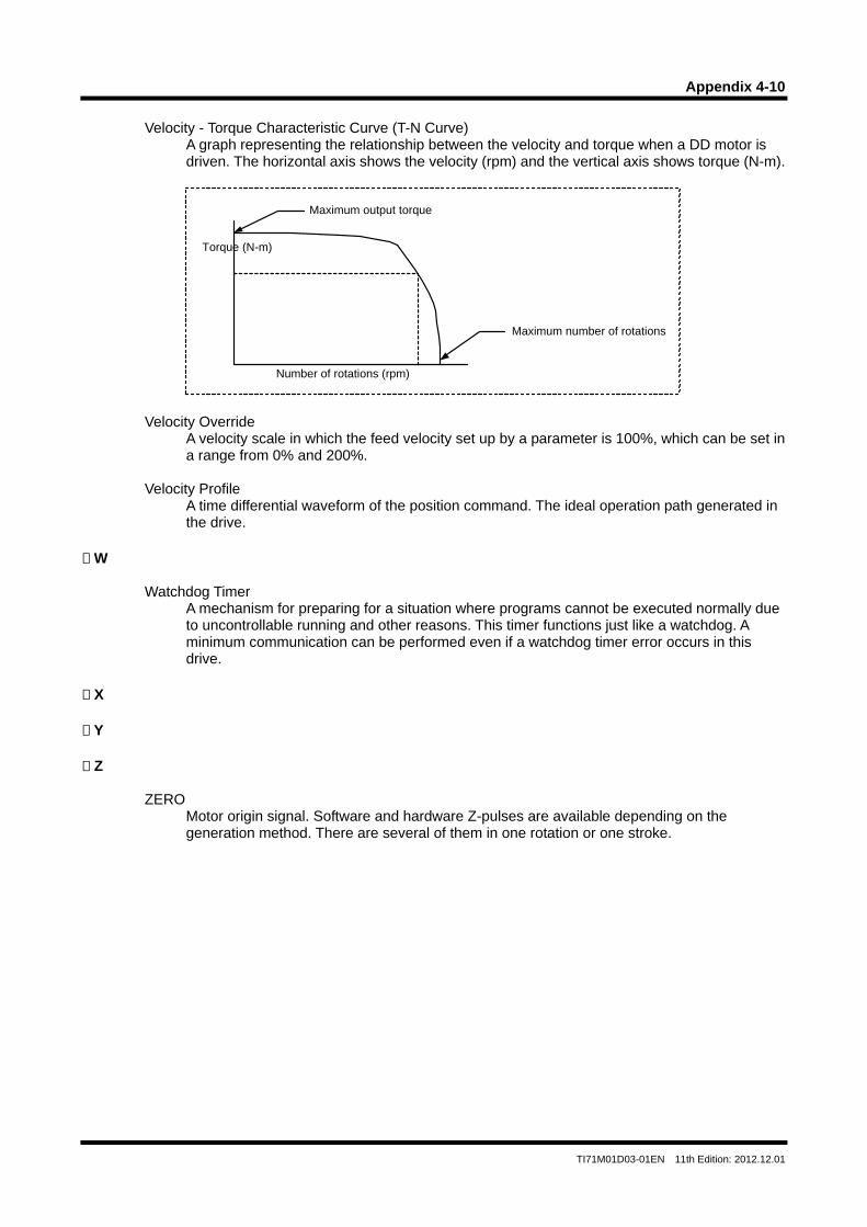
Appendix 4-10
TI71M01D03-01EN 11th Edition: 2012.12.01
Velocity - Torque Characteristic Curve (T-N Curve)
A graph representing the relationship between the velocity and torque when a DD motor is driven. The horizontal axis shows the velocity (rpm) and the vertical axis shows torque (N-m).
Velocity Override
A velocity scale in which the feed velocity set up by a parameter is 100%, which can be set in a range from 0% and 200%.
Velocity Profile
A time differential waveform of the position command. The ideal operation path generated in the drive.
W
Watchdog Timer A mechanism for preparing for a situation where programs cannot be executed normally due to uncontrollable running and other reasons. This timer functions just like a watchdog. A minimum communication can be performed even if a watchdog timer error occurs in this drive.
X Y Z
ZERO Motor origin signal. Software and hardware Z-pulses are available depending on the generation method. There are several of them in one rotation or one stroke.
Number of rotations (rpm)
Torque (N-m)
Maximum output torque
Maximum number of rotations
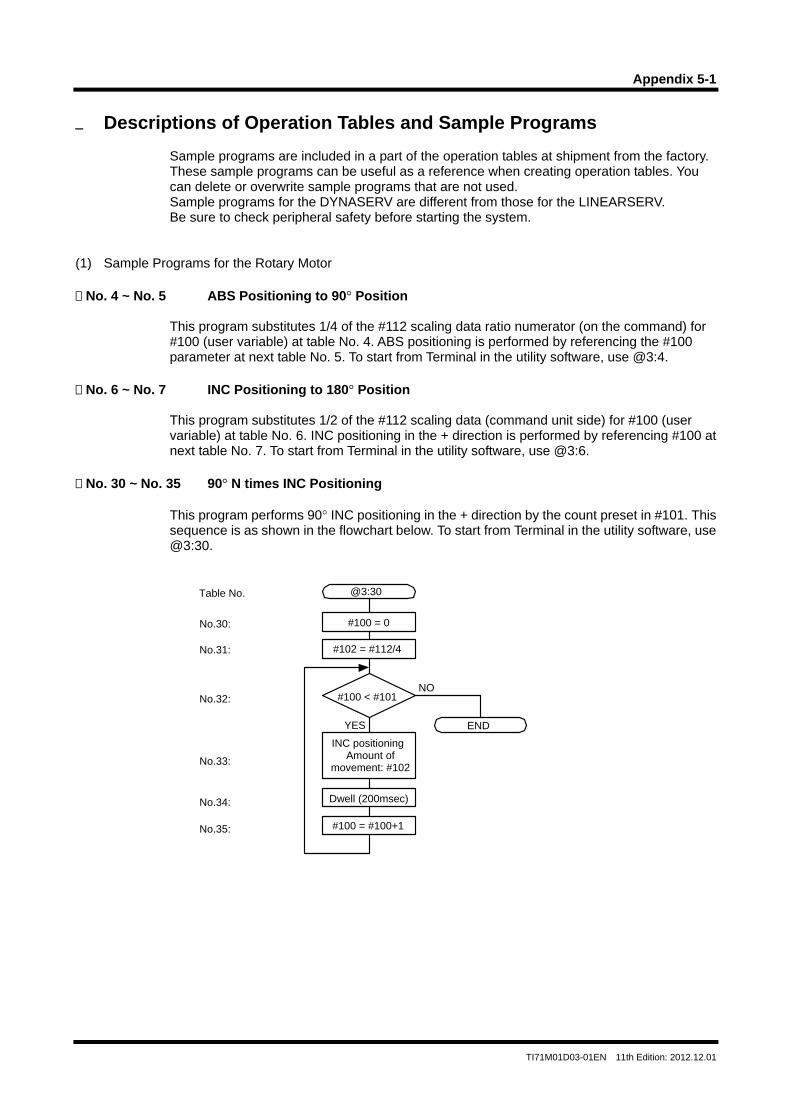
Appendix 5-1
TI71M01D03-01EN 11th Edition: 2012.12.01
Descriptions of Operation Tables and Sample Programs
Sample programs are included in a part of the operation tables at shipment from the factory. These sample programs can be useful as a reference when creating operation tables. You can delete or overwrite sample programs that are not used. Sample programs for the DYNASERV are different from those for the LINEARSERV. Be sure to check peripheral safety before starting the system.
(1) Sample Programs for the Rotary Motor No. 4 ~ No. 5 ABS Positioning to 90° Position
This program substitutes 1/4 of the #112 scaling data ratio numerator (on the command) for #100 (user variable) at table No. 4. ABS positioning is performed by referencing the #100 parameter at next table No. 5. To start from Terminal in the utility software, use @3:4.
No. 6 ~ No. 7 INC Positioning to 180° Position
This program substitutes 1/2 of the #112 scaling data (command unit side) for #100 (user variable) at table No. 6. INC positioning in the + direction is performed by referencing #100 at next table No. 7. To start from Terminal in the utility software, use @3:6.
No. 30 ~ No. 35 90° N times INC Positioning
This program performs 90° INC positioning in the + direction by the count preset in #101. This sequence is as shown in the flowchart below. To start from Terminal in the utility software, use @3:30.
#100 = 0
#102 = #112/4
#100 < #101
INC positioning Amount of
movement: #102
Dwell (200msec)
#100 = #100+1
@3:30
No.30:
Table No.
No.31:
No.32:
No.33:
No.34:
No.35:
YES
NO
END
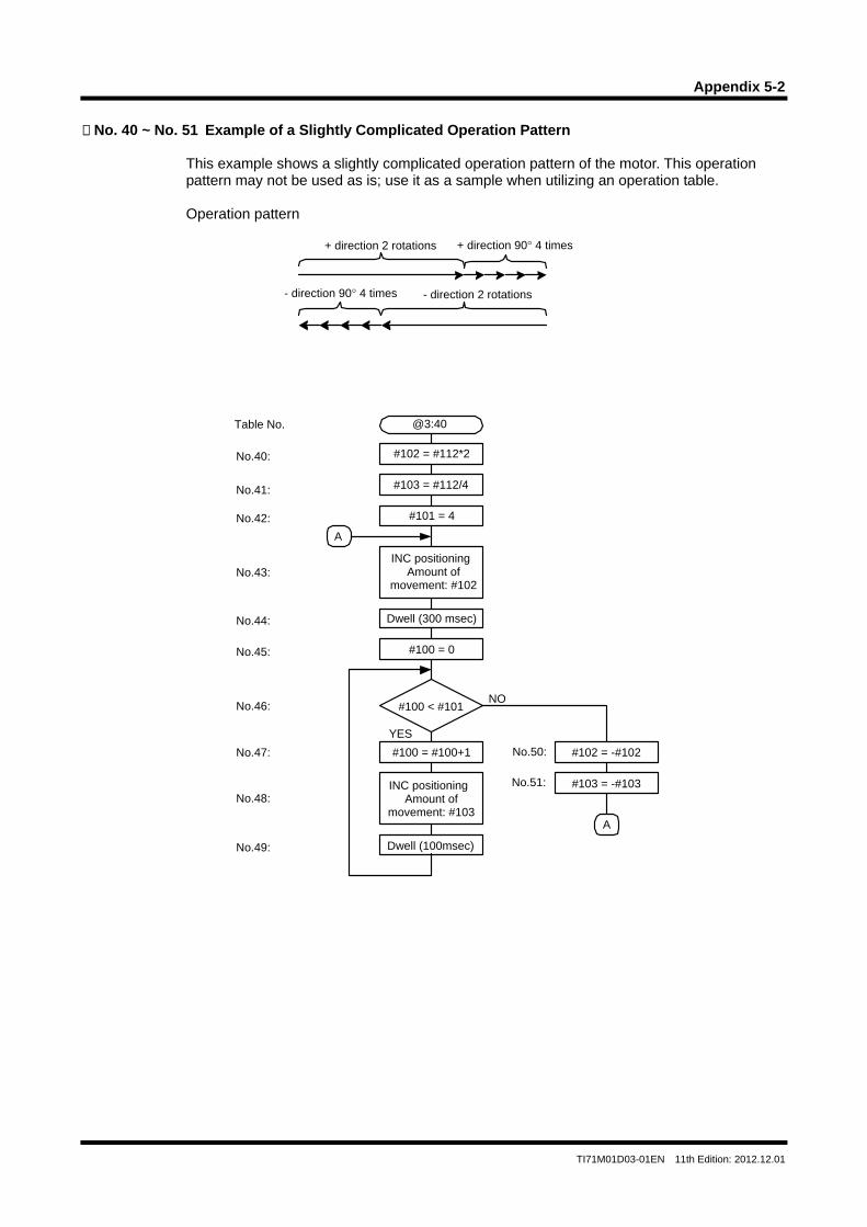
Appendix 5-2
TI71M01D03-01EN 11th Edition: 2012.12.01
No. 40 ~ No. 51 Example of a Slightly Complicated Operation Pattern
This example shows a slightly complicated operation pattern of the motor. This operation pattern may not be used as is; use it as a sample when utilizing an operation table.
Operation pattern
+ direction 2 rotations + direction 90° 4 times
- direction 90° 4 times - direction 2 rotations
#102 = #112*2
#103 = #112/4
#100 < #101
INC positioning Amount of
movement: #102
@3:40
No.40:
Table No.
YES
NO
#101 = 4
Dwell (300 msec)
#100 = 0
#100 = #100+1
INC positioning Amount of
movement: #103
Dwell (100msec)
#102 = -#102
#103 = -#103
No.41:
No.42:
No.43:
No.44:
No.45:
No.46:
No.47:
No.48:
No.49:
No.50:
No.51:
A
A
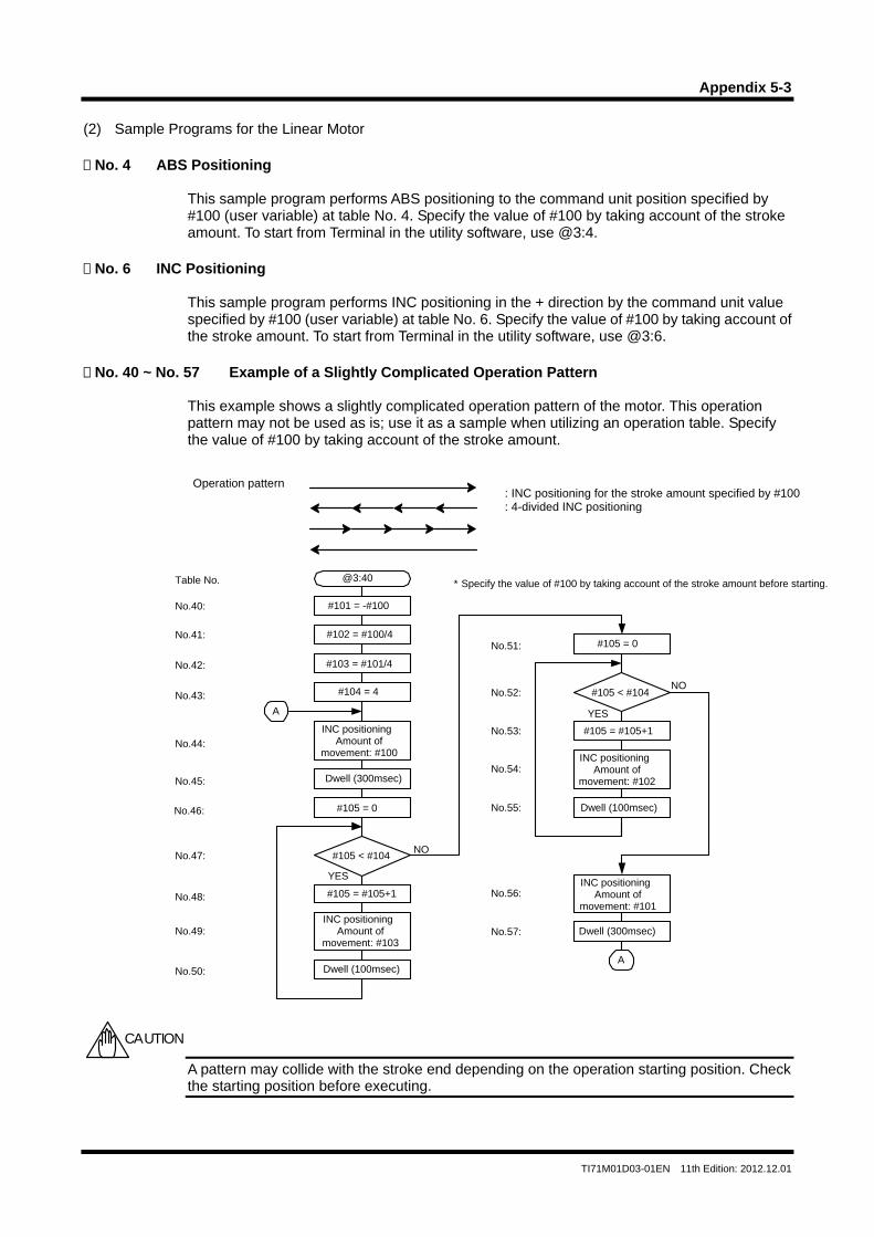
Appendix 5-3
TI71M01D03-01EN 11th Edition: 2012.12.01
(2) Sample Programs for the Linear Motor No. 4 ABS Positioning
This sample program performs ABS positioning to the command unit position specified by #100 (user variable) at table No. 4. Specify the value of #100 by taking account of the stroke amount. To start from Terminal in the utility software, use @3:4.
No. 6 INC Positioning
This sample program performs INC positioning in the + direction by the command unit value specified by #100 (user variable) at table No. 6. Specify the value of #100 by taking account of the stroke amount. To start from Terminal in the utility software, use @3:6.
No. 40 ~ No. 57 Example of a Slightly Complicated Operation Pattern
This example shows a slightly complicated operation pattern of the motor. This operation pattern may not be used as is; use it as a sample when utilizing an operation table. Specify the value of #100 by taking account of the stroke amount.
A pattern may collide with the stroke end depending on the operation starting position. Check the starting position before executing.
CAUTION
Operation pattern : INC positioning for the stroke amount specified by #100: 4-divided INC positioning
#101 = -#100
@3:40
No.40:
Table No. * Specify the value of #100 by taking account of the stroke amount before starting.
#102 = #100/4
#103 = #101/4
INC positioning Amount of
movement: #100
Dwell (300msec)
#104 = 4
#105 = 0
#105 < #104
YES
NO
#105 = #105+1
INC positioning Amount of
movement: #103
Dwell (100msec)
#105 = 0
#105 < #104
YES
NO
#105 = #105+1
INC positioning Amount of
movement: #102
Dwell (100msec)
INC positioning Amount of
movement: #101
Dwell (300msec)
No.41:
No.42:
No.43:
No.44:
No.45:
No.46:
No.47:
No.48:
No.49:
No.50:
No.51:
No.52:
No.53:
No.54:
No.55:
No.56:
No.57:
A
A

Blank Page
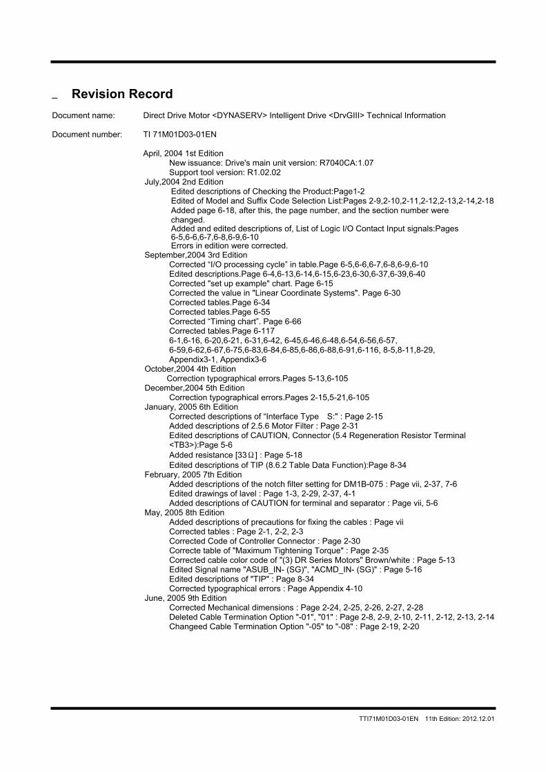
TTI71M01D03-01EN 11th Edition: 2012.12.01
Revision Record Document name: Direct Drive Motor <DYNASERV> Intelligent Drive <DrvGIII> Technical Information Document number: TI 71M01D03-01EN
April, 2004 1st Edition New issuance: Drive's main unit version: R7040CA:1.07 Support tool version: R1.02.02
July,2004 2nd Edition Edited descriptions of Checking the Product:Page1-2 Edited of Model and Suffix Code Selection List:Pages 2-9,2-10,2-11,2-12,2-13,2-14,2-18 Added page 6-18, after this, the page number, and the section number were changed. Added and edited descriptions of, List of Logic I/O Contact Input signals:Pages 6-5,6-6,6-7,6-8,6-9,6-10 Errors in edition were corrected.
September,2004 3rd Edition Corrected “I/O processing cycle” in table.Page 6-5,6-6,6-7,6-8,6-9,6-10 Edited descriptions.Page 6-4,6-13,6-14,6-15,6-23,6-30,6-37,6-39,6-40 Corrected "set up example" chart. Page 6-15 Corrected the value in "Linear Coordinate Systems". Page 6-30 Corrected tables.Page 6-34 Corrected tables.Page 6-55 Corrected “Timing chart”. Page 6-66 Corrected tables.Page 6-117 6-1,6-16, 6-20,6-21, 6-31,6-42, 6-45,6-46,6-48,6-54,6-56,6-57, 6-59,6-62,6-67,6-75,6-83,6-84,6-85,6-86,6-88,6-91,6-116, 8-5,8-11,8-29, Appendix3-1, Appendix3-6
October,2004 4th Edition Correction typographical errors.Pages 5-13,6-105
December,2004 5th Edition Correction typographical errors.Pages 2-15,5-21,6-105
January, 2005 6th Edition Corrected descriptions of “Interface Type S:" : Page 2-15 Added descriptions of 2.5.6 Motor Filter : Page 2-31 Edited descriptions of CAUTION, Connector (5.4 Regeneration Resistor Terminal <TB3>):Page 5-6 Added resistance [33Ω] : Page 5-18 Edited descriptions of TIP (8.6.2 Table Data Function):Page 8-34
February, 2005 7th Edition Added descriptions of the notch filter setting for DM1B-075 : Page vii, 2-37, 7-6 Edited drawings of lavel : Page 1-3, 2-29, 2-37, 4-1 Added descriptions of CAUTION for terminal and separator : Page vii, 5-6
May, 2005 8th Edition Added descriptions of precautions for fixing the cables : Page vii Corrected tables : Page 2-1, 2-2, 2-3 Corrected Code of Controller Connector : Page 2-30 Correcte table of "Maximum Tightening Torque" : Page 2-35 Corrected cable color code of "(3) DR Series Motors" Brown/white : Page 5-13 Edited Signal name "ASUB_IN- (SG)", "ACMD_IN- (SG)" : Page 5-16 Edited descriptions of "TIP" : Page 8-34 Corrected typographical errors : Page Appendix 4-10
June, 2005 9th Edition Corrected Mechanical dimensions : Page 2-24, 2-25, 2-26, 2-27, 2-28 Deleted Cable Termination Option "-01", "01" : Page 2-8, 2-9, 2-10, 2-11, 2-12, 2-13, 2-14 Changeed Cable Termination Option "-05" to "-08" : Page 2-19, 2-20
TTI71M01D03-01EN 11th Edition: 2012.12.01
June, 2006 10th Edition
Drive's main unit version: R7040CA: v1.24
Support tool version: R1.03.03 Corrected "regenerative resistor" : Page vii, TOC1, TOC2, 1-2, 1-3, 2-5, 2-30, 2-31, 2-46, 4-2, 4-3, 4-4, 5-6, Appendix3-2 Added descriptions of maximum rate of pulse input : Page 6-105, Appendix3-3 Corrected discriptions in tables : Page 2-1, 2-2, 2-5, 2-48, 5-13, 5-16, 5-17, 5-18 Added specification of control power supply : Page 2-5 Changed Cable Termination Option : Page 2-8 to 2-14, 2-16, 2-19, 2-20 Corrected connector parts number : Page 2-19, 2-20,02-30 Changed tables : Page 2-19, 2-20, 2-35 Corrected outline drawings : Page 2-24, 2-27 Corrected unites : Page 2-33 Corrected varistor parts number : Page 2-34 Corrected position of "tcy" in a graph: Page 2-45 Edited parts number of motor fitler : Page 5-2 Edited descriptions of recommended cables : Page 5-12, 5-13 Added discriptions : Page 6-105, 8-41, 9-2 Added a section for Filter Tuning : Page 8-33 Edited descriptions of URL : Page revision record
Decenber, 2012 11th Edition Change of Document Number TI 71M01D03-01E> TI 71M01D03-01EN Added General Precautions Regarding DYNASERV : Page vii Added UL Standard Certification Conditions and Safety Precautions : Page 2-48 Change of department name : Page revision record Changed Motor cable size : Page 2-24, 2-25, 2-26 Added Error code 2.0, 11.7, 14.1~14.5, 19.1, 19.2, 20.6, : Appendix 3
Copyright Yokogawa Electric Corporation Motion Control Center Publisher Yokogawa Electric Corporation 2-9-32, Nakacho, Musashino-shi, Tokyo, 180-8750, Japan URL: http://www.yokogawa.com/ddm