direct matrix factorization and alignment …zqin001/crv2014.pdfdirect matrix factorization and...
TRANSCRIPT

Direct Matrix Factorization and Alignment Refinement: Application to DefectDetection
Zhen QinUniversity of California, Riverside
Peter van Beek Xu ChenSharp Laboratories of America{pvanbeek, chenx}@sharplabs.com
Abstract—Defect detection approaches based on templatedifferencing require precise alignment of the input and tem-plate image; however, such alignment is easily affected by thepresence of defects. Often, non-trivial pre/post-processing stepsand/or manual parameter tuning are needed to remove falsealarms, complicating the system and hampering automation.In this work, we explicitly address alignment and defectextraction jointly, and provide a general iterative algorithmto improve both their performance to pixel-wise accuracy.We achieve this by utilizing and extending the robust rankminimization and alignment method of [12]. We propose aneffective and efficient optimization algorithm to decompose atemplate-guided image matrix into a low-rank part relatingto alignment-refined defect-free images and an explicit errorcomponent containing the defects of interest. Our algorithmis fully automatic, training-free, only needs trivial pre/post-processing procedures, and has few parameters. The rankminimization formulation only requires a linearly correlatedtemplate image, and a template-guided approach relieves thecommon assumption of small defects, making our systemvery general. We demonstrate the performance of our novelapproach qualitatively and quantitatively on a real-world data-set with defects of varying appearance.
Keywords-Defect Detection; Industrial Inspection; TemplateMatching; Image Alignment; Matrix Factorization
I. INTRODUCTION
Defect detection on fabric, electronic panels, surfacemounted devices (SMD), printed circuit board (PCB), etc. isa critical procedure in industry. Highly accurate, consistentand scalable automatic defect detection systems are neededto improve process yield and product quality. However,designing such a system is very challenging, due to thehighly unpredictable characteristics of real-world defects. Ashinted in Fig. 1, real-world defects possess extraordinaryvariability in terms of appearance, shape and size, and areoften specific to the object class inspected. It is desirableto design a general defect detection method that works forvarious known or even unknown defects and inspected objecttypes.
Motivated by the following reasons, we seek a defect de-tection solution based on the template differencing approach:
This work was done during the first author’s internship at Sharp Labo-ratories of America.
Figure 1: Examples of various real-world defects, indicatedby the green ellipses. Defects may have arbitrary shapes, bespecific to the object class examined, possess weak intensi-ties, and have large sizes. The inspected objects themselvesalso vary strongly.
• This approach is very general and makes no assumptionsabout defect/object characteristics, by only seeking todetect “differences” between the input image and a defect-free template.
• Training data is generally not needed. In our case, we onlyneed a single defect-free template image, which is usuallynot a problem. Acquiring large amounts of (labeled)training data can be problematic and time-consuming.Template differencing approaches to defect detection
highly rely on accurate alignment between the input andtemplate images. To the best of our knowledge, all exist-ing defect detection approaches apply alignment as a pre-processing step. However, alignment can easily be affectedby the existence of defects, especially if the defects are largeor have strong edges/texture. In order to tackle this problem,we propose to conduct alignment refinement while handlingestimated defects in an explicit error measurement, jointlyoptimizing for both. We utilize and extend a method termedRobust Alignment by Sparse and Low-rank decomposition(RASL) [12], which was proposed for batch alignment ofhundreds of images. Our formulation is aimed at optimaldecomposition of an image matrix that contains both theinput and template image into a low-rank part relating toaligned defect-free images and an error component thatcaptures the defect signal. Extracting a defect mask fromthe error component becomes trivial and requires no post-processing.
Our optimization approach applies recent advances inrobust rank minimization that have caught much attention
in the computer vision community. The work of RobustPrinciple Component Analysis (RPCA) [3] showed that itis possible to efficiently recover low-rank matrices despitesignificant corruptions. Further, it has been shown that theclaim holds when entry-wise noise exists [21]. In theseworks, the initial formulation of optimizing a matrix rankand l0 norm is relaxed to optimizing a nuclear norm and l1norm. Very recent work [19] [20] shows that this relaxationmay not be neccessary and direct factorization is possible.
Our contributions include:1. We propose an effective and efficient optimization frame-
work for defect detection termed Direct matrix Factoriza-tion and Alignment Refinement (DFAR). We iterativelyimprove both alignment and defect detection performanceusing an efficient algorithm. To the best of our knowledge,our application of robust rank minimization (jointly withalignment) to industrial defect detection is a first inliterature.
2. Our derivation initially follows that of RASL ([12]);however, our algorithm is different from RASL in severalaspects. Our algorithm does not rely on the relaxation ofmatrix rank to nuclear norm and l0 norm to l1 norm;instead we apply direct factorization as in [19] [20]. Ourformulation considers entry-wise noise, not consideredin RASL. We construct the image matrix from bothinput images and template images; this template-guidedapproach relaxes the sparsity assumption of the defects.We found that directly applying batch alignment did notwork.
3. We demonstrate the precision-recall performance andefficiency of our algorithm with several experiments on areal-world industrial defect image dataset. We compareour approach to RASL as well as to several existing(template-based and template-free) defect detection meth-ods.The proposed algorithm (DFAR) is very general, training-
free, only assumes a template image that is linearly cor-related with respect to the input, and provides accuratealignment and defect localization, relieving the need for non-trivial application-specific pre/post-processing procedures.DFAR only has a few parameters that have clear meaning,making the algorithm easy to use.
Before presenting the proposed defect detection approachin detail in Sec. II and experimental results in Sec. III, wediscuss related work in the following subsection.
A. Related Work
Several defect detection methods based on template dif-ferencing have been proposed. Often, the input image isfirstly registered with a defect-free template using variousregistration algorithms, followed by localized direct differ-encing [13], optical flow [17], normalized cross correlation(NCC) [16], wavelet-based processing [6], or Hausdorffdistance measurement [5]. Unfortunately, existing defect
detection methods are still largely application-specific. Forexample, [13] and [17] are aimed only at semiconductorwafers; [6] and [5] focus on SMD and PCB assemblyrespectively. Furthermore, most systems occasionally needtraining and manual intervention [17], mostly work only forsmall defects, and most are sensitive to parameter changes.
These undesirable features result from various assump-tions made during algorithm design, for example: assump-tions about the existence of some fixed landmark pointsfor alignment [5], or assumptions about the nature of theinspected surface [16]. More importantly, almost all existingtemplate differencing methods assume a superior registra-tion/alignment performance; but even state-of-art alignmentalgorithms might cause misalignment and raise false alarmsto some extent. Therefore, in practice, manual adjustment(then perfect alignment is assumed), the assumption ofsmall defects (which shall hurt alignment performance less),and/or non-trivial pre/post-processing procedures are ap-plied, introducing complexity and reducing generality.
Several methods other than template differencing are thefollowing.• Detection based on supervised classification is one major
category of detection methods for targets such as humanand vehicles [18][7]. In real-world industrial scenarios, itis difficult to gather a reasonable size of training sampleswith labeled defect masks. Given the high intra- and inter-class variance of possible defects, designing features isalso difficult.
• Defect detection based on saliency detection [2][14][9][4]also poses challenges. State-of-art saliency detectionmethods typically estimate a coarse and subjectivesaliency support on natural images which is far fromthe industrial accuracy requirement. Also, these methodsusually make a number of assumptions.
• Anomaly detection methods such as PHOT [1], whichanalyze images in the Fourier domain, may only locatesmall defects on uniformly textured or periodic patternedimages, such as fabric surface. We shall show in exper-iments that our algorithm generalizes to such types ofimages.
II. PROPOSED DEFECT DETECTION APPROACH
We first give an overview of the detection system and in-troduce the problem formulation of decomposing vectorizedimage matrix to achieve simultaneous alignment refinementand defect estimation. Then we introduce our effective andefficient optimization algorithm with steps that can be solvedby off-the-shelf algorithms.
A. System Overview
Our proposed framework is presented in Fig. 2. We firstuse a hierarchical framework that locates the input candidateon the whole template image. After evaluating a number ofexisting registration techniques, we find [8] provides best

Figure 2: An overview of our system. After initial regis-tration, alignment is refined while maintaining an explicitmeasurement of the errors, where defect mask can be easilygenerated from. Notice the misalignment and illuminationdifference between the input and template images. For theerror images, color closer to red indicates higher intensity.
overall accuracy and scalability and we omit the details here.However, even with this state-of-art registration method,initial misalignments still generally exist. We next describeour proposed method for simultaneous alignment refinementand defect extraction, given the input image and the corre-sponding (but not perfectly aligned) template image.
B. Problem Formulation
Suppose we have the well-aligned, defect-free single-channel input image I0
1 and template images I02 . . . I
0n ∈
Rw×h, we define vec : Rw×h → Rm as the operatorthat stack the corresponding pixels as a vector. The single-channel images may be grayscale or luminance data, orsimply contain the green channel of an RGB image. We usemultiple template images as will be explained in Sec. II-D.Then the matrix A .
= [vec(I01 )| . . . |vec(I0
n)] ∈ Rm×n shouldbe low-rank. Low-rank indicates that the input image shouldbe linearly correlated with the template image. Anotherway to view it is that the columns of matrix A should benearly constant regardless of global intensity changes due toillumination.
However, the images we observe are neither well-alignednor defect-free, which can be represented as Ii = (I0
i +ei + εi) ◦ τ−1
i , where ei is an additive error componentwherein we intend the defects are contained and is assumedto be sparse, τ−1
i ∈ G is a transformation that modelsthe practical misalignment, and εi models the noise. Inthis work, G corresponds to the similarity, affine or pla-nar homography group of parametric transforms. Now ouraim is to decompose the aligned observed image matrixD ◦ τ .
= [vec(I1 ◦ τ1)| . . . |vec(In ◦ τn)] ∈ Rm×n as
D ◦ τ = A+ E + ε, (1)
where E.= [vec(e1)| . . . |vec(en)] ∈ Rm×nand ε models
real-world entry-wise noise. In other words, we want to
decompose the aligned observed images D ◦ τ into: a low-rank component A that should relate to the defect-freebackground, a sparse error component E that we expect tocontain the defects, and a noise term. A direct formulationof the problem can be posed as a constrained optimizationproblem:
minA,E,τ
||D ◦ τ − E −A||F
s.t. rank(A) ≤ K||E||0 ≤ γ
(2)
where || · ||F is the Frobenius norm, K is the rank constrainton the low-rank approximation A, and γ is the maximalnumber of non-zero entries in E. Intuitively, we can ap-proximate the low-rank component reliably, since D ◦τ −Ecan be viewed as the aligned image matrix excluding thedefects. We will directly solve this optimization problem inthe primal form.
C. Optimization
We solve this problem effectively and efficiently withoutrelaxing either the rank or the cardinality constraint, orreferring to the Lagrangian. We term our algorithm as directfactorization and alignment refinement (DFAR).
First, since the dependence of D◦τ is complicated on thetransformations τ , when the change in τ is small, we canapproximate the dependency by linearizing about the currentestimate of τ , as commonly done in the alignment literature[15] [12]. Then the optimization problem becomes
minA,E,∆τ
||(D ◦ τ +∑i
Ji∆τiµTi − E)−A||F
s.t. rank(A) ≤ K||E||0 ≤ γ
(3)
where Ji.= ∂
∂δvec(Ii ◦ δ)|δ=τi is the Jacobian of the i-thimage with respect to the transformation τi, and µi is the i-th standard basis for Rn (for a compact presentation). Sincethe linearization only holds locally, we repeatedly linearizeabout the current transformations and solve the problem ofthe form of Eq. 3.
Given the current estimate of transformations τ and errorE (the very first transformation is identity transform andall elements of E are zeros), we take advantage of thenice decomposable structure of our formulation and applyblock coordinate descent with respect to A, E and, ∆τ . Theresulting algorithm is described in Alg. 1 and Alg. 2. Notethat Alg. 1, the outer loop, is very similar to that of RASL[12], and is not discussed further.
The solution to step 1) in Alg. 2, a low-rank approxima-tion problem, is directly and optimally given by standardtruncated Singular Value Decomposition (SVD) approxima-tion to the matrix (D ◦ τ +
∑i Ji∆τiµ
Ti − E), or we can
accelerate this process by referring to partial SVD algorithmssuch as [10].
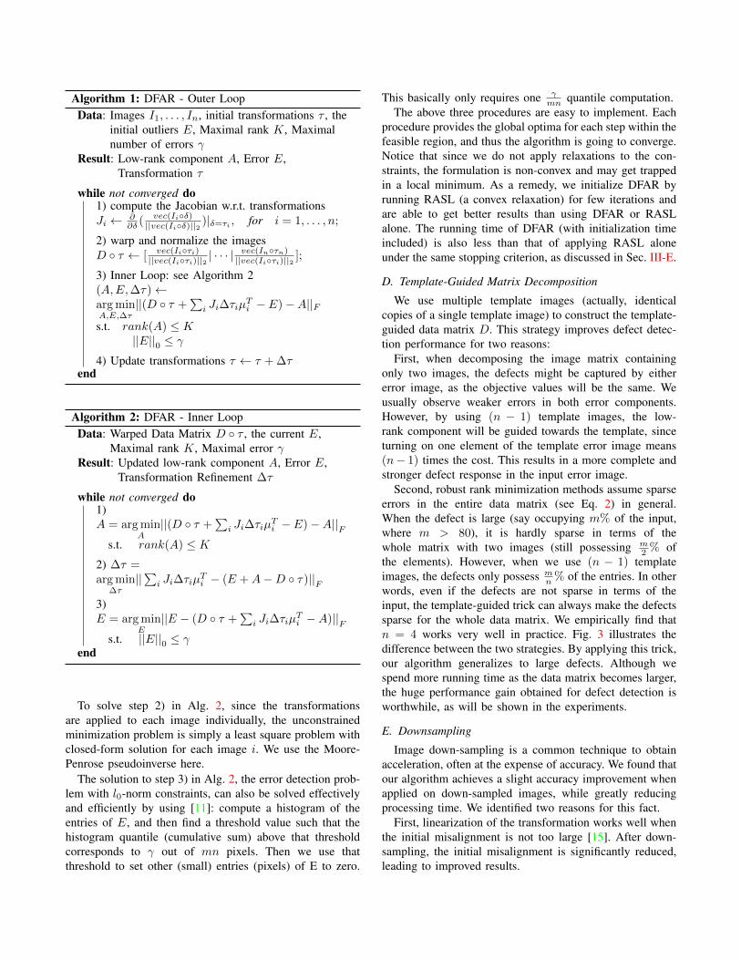
Algorithm 1: DFAR - Outer LoopData: Images I1, . . . , In, initial transformations τ , the
initial outliers E, Maximal rank K, Maximalnumber of errors γ
Result: Low-rank component A, Error E,Transformation τ
while not converged do1) compute the Jacobian w.r.t. transformationsJi ← ∂
∂δ ( vec(Ii◦δ)||vec(Ii◦δ)||2 )|δ=τi , for i = 1, . . . , n;
2) warp and normalize the imagesD ◦ τ ← [ vec(Ii◦τi)
||vec(Ii◦τi)||2 | · · · |vec(In◦τn)||vec(Ii◦τi)||2 ];
3) Inner Loop: see Algorithm 2(A,E,∆τ)←arg minA,E,∆τ
||(D ◦ τ +∑i Ji∆τiµ
Ti − E)−A||F
s.t. rank(A) ≤ K||E||0 ≤ γ
4) Update transformations τ ← τ + ∆τend
Algorithm 2: DFAR - Inner LoopData: Warped Data Matrix D ◦ τ , the current E,
Maximal rank K, Maximal error γResult: Updated low-rank component A, Error E,
Transformation Refinement ∆τ
while not converged do1)A = arg min
A||(D ◦ τ +
∑i Ji∆τiµ
Ti − E)−A||
F
s.t. rank(A) ≤ K2) ∆τ =arg min
∆τ||∑i Ji∆τiµ
Ti − (E +A−D ◦ τ)||
F
3)E = arg min
E||E − (D ◦ τ +
∑i Ji∆τiµ
Ti −A)||
F
s.t. ||E||0 ≤ γend
To solve step 2) in Alg. 2, since the transformationsare applied to each image individually, the unconstrainedminimization problem is simply a least square problem withclosed-form solution for each image i. We use the Moore-Penrose pseudoinverse here.
The solution to step 3) in Alg. 2, the error detection prob-lem with l0-norm constraints, can also be solved effectivelyand efficiently by using [11]: compute a histogram of theentries of E, and then find a threshold value such that thehistogram quantile (cumulative sum) above that thresholdcorresponds to γ out of mn pixels. Then we use thatthreshold to set other (small) entries (pixels) of E to zero.
This basically only requires one γmn quantile computation.
The above three procedures are easy to implement. Eachprocedure provides the global optima for each step within thefeasible region, and thus the algorithm is going to converge.Notice that since we do not apply relaxations to the con-straints, the formulation is non-convex and may get trappedin a local minimum. As a remedy, we initialize DFAR byrunning RASL (a convex relaxation) for few iterations andare able to get better results than using DFAR or RASLalone. The running time of DFAR (with initialization timeincluded) is also less than that of applying RASL aloneunder the same stopping criterion, as discussed in Sec. III-E.
D. Template-Guided Matrix Decomposition
We use multiple template images (actually, identicalcopies of a single template image) to construct the template-guided data matrix D. This strategy improves defect detec-tion performance for two reasons:
First, when decomposing the image matrix containingonly two images, the defects might be captured by eithererror image, as the objective values will be the same. Weusually observe weaker errors in both error components.However, by using (n − 1) template images, the low-rank component will be guided towards the template, sinceturning on one element of the template error image means(n− 1) times the cost. This results in a more complete andstronger defect response in the input error image.
Second, robust rank minimization methods assume sparseerrors in the entire data matrix (see Eq. 2) in general.When the defect is large (say occupying m% of the input,where m > 80), it is hardly sparse in terms of thewhole matrix with two images (still possessing m
2 % ofthe elements). However, when we use (n − 1) templateimages, the defects only possess m
n % of the entries. In otherwords, even if the defects are not sparse in terms of theinput, the template-guided trick can always make the defectssparse for the whole data matrix. We empirically find thatn = 4 works very well in practice. Fig. 3 illustrates thedifference between the two strategies. By applying this trick,our algorithm generalizes to large defects. Although wespend more running time as the data matrix becomes larger,the huge performance gain obtained for defect detection isworthwhile, as will be shown in the experiments.
E. Downsampling
Image down-sampling is a common technique to obtainacceleration, often at the expense of accuracy. We found thatour algorithm achieves a slight accuracy improvement whenapplied on down-sampled images, while greatly reducingprocessing time. We identified two reasons for this fact.
First, linearization of the transformation works well whenthe initial misalignment is not too large [15]. After down-sampling, the initial misalignment is significantly reduced,leading to improved results.
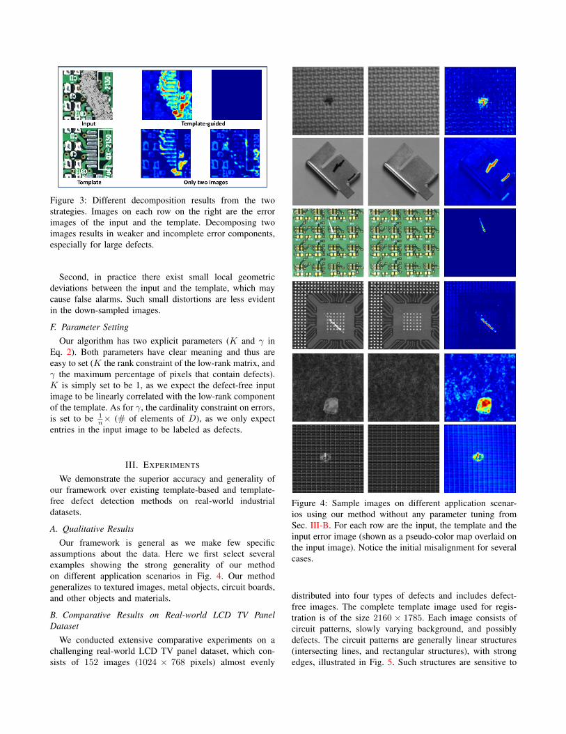
Figure 3: Different decomposition results from the twostrategies. Images on each row on the right are the errorimages of the input and the template. Decomposing twoimages results in weaker and incomplete error components,especially for large defects.
Second, in practice there exist small local geometricdeviations between the input and the template, which maycause false alarms. Such small distortions are less evidentin the down-sampled images.
F. Parameter Setting
Our algorithm has two explicit parameters (K and γ inEq. 2). Both parameters have clear meaning and thus areeasy to set (K the rank constraint of the low-rank matrix, andγ the maximum percentage of pixels that contain defects).K is simply set to be 1, as we expect the defect-free inputimage to be linearly correlated with the low-rank componentof the template. As for γ, the cardinality constraint on errors,is set to be 1
n× (# of elements of D), as we only expectentries in the input image to be labeled as defects.
III. EXPERIMENTS
We demonstrate the superior accuracy and generality ofour framework over existing template-based and template-free defect detection methods on real-world industrialdatasets.
A. Qualitative Results
Our framework is general as we make few specificassumptions about the data. Here we first select severalexamples showing the strong generality of our methodon different application scenarios in Fig. 4. Our methodgeneralizes to textured images, metal objects, circuit boards,and other objects and materials.
B. Comparative Results on Real-world LCD TV PanelDataset
We conducted extensive comparative experiments on achallenging real-world LCD TV panel dataset, which con-sists of 152 images (1024 × 768 pixels) almost evenly
Figure 4: Sample images on different application scenar-ios using our method without any parameter tuning fromSec. III-B. For each row are the input, the template and theinput error image (shown as a pseudo-color map overlaid onthe input image). Notice the initial misalignment for severalcases.
distributed into four types of defects and includes defect-free images. The complete template image used for regis-tration is of the size 2160 × 1785. Each image consists ofcircuit patterns, slowly varying background, and possiblydefects. The circuit patterns are generally linear structures(intersecting lines, and rectangular structures), with strongedges, illustrated in Fig. 5. Such structures are sensitive to
misalignment during defect detection. We are unable to showcomplete input images (with defects) in this paper due toconfidentiality reasons. We describe the four defect typesand their characteristics in Tbl. I.
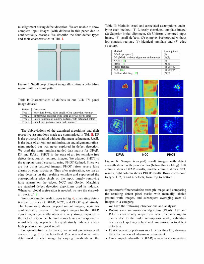
Figure 5: Small crop of input image illustrating a defect-freeregion with a circuit pattern.
Table I: Characteristics of defects in our LCD TV panelimage dataset.
Defect DescriptionType 1 Very dark blobs, often small, often somewhat circularType 2 Superfluous material with same color as circuit linesType 3 Large transparent rainbow patterns with saturated colorsType 4 Small dots patterns, with dark intensity
The abbreviations of the examined algorithms and theirrespective assumptions made are summarized in Tbl. II. DFis the proposed method without alignment refinement. RASLis the state-of-art on rank minimization and alignment refine-ment method but was never explored in defect detection.We used the same template-guided data matrix for DFAR,DF and RASL. PHOT is the state-of-art for template-freedefect detection on textured images. We adapted PHOT tothe template-based scenario, using PHOT-Refined. Since weare not using textured images, PHOT raises severe falsealarms on edge structures. Thus after registration, we ran anedge detector on the resulting template and suppressed thecorresponding edge pixels on the input, largely removingfalse alarms on the edges. NCC and Golden Matchingare standard defect detection algorithms used in industry.Whenever global registration is needed, we use the state-of-art work of [8].
We show sample result images in Fig. 6, illustrating detec-tion performance of DFAR, NCC, and PHOT qualitatively.The figure only shows cropped output images, again forconfidentiality reasons. In the output images for the DFARalgorithm, we generally observe a very strong response inthe defect region pixels, and a much weaker response innon-defect region pixels. This qualitatively indicates a veryhigh precision and good recall.
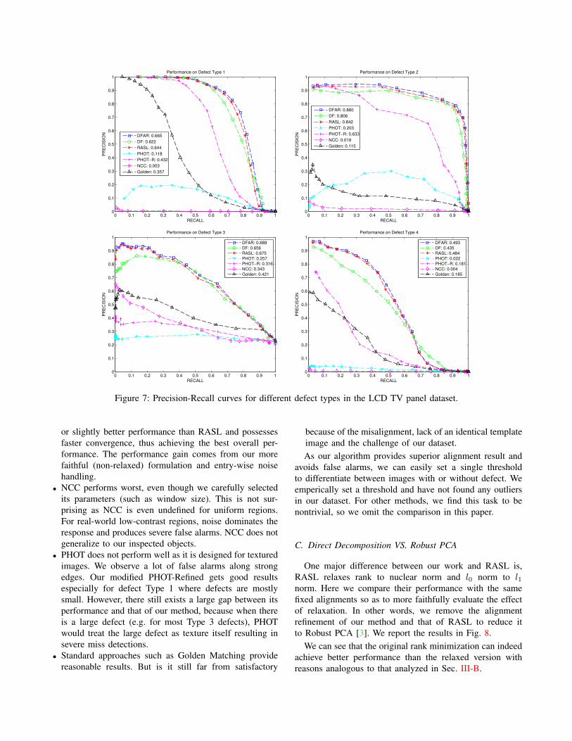
For quantitative performance, we report precision-recallcurves in Fig. 7 for each method. Precision and recall weredetermined for each image by varying thresholds on the
Table II: Methods tested and associated assumptions under-lying each method: (1) Linearly correlated template image,(2) Superior initial alignment, (3) Uniformly textured inputimage, (4) small defects, (5) complex background withoutlow-contrast regions, (6) identical template and (7) edgestructure.
Method AssumptionsDFAR (proposed) (1)DF (DFAR without alignment refinement) (1)(2)RASL [12] (1)PHOT [1] (3)(4)PHOT-Refined (1)(2)(4)(7)NCC [16] (1)(2)(4)(5)Golden Matching [13] (2)(6)
Figure 6: Sample (cropped) result images with defectstrength shown with pseudo-color (before thresholding). Leftcolumn shows DFAR results, middle column shows NCCresults, right column shows PHOT results. Rows correspondto type 1, 2, 3 and 4 defects, from top to bottom.
output error/difference/defect strength image, and comparingthe resulting defect pixel masks with manually labeledground truth images, and subsequent averaging over allimages in a category.
We have the following observations and analysis:• Robust rank minimization algorithm (DFAR, DF and
RASL) consistently outperform other methods signifi-cantly due to the mild assumptions made, validatingour idea of applying robust rank minimization to defectdetection.
• DFAR generally performs much better than DF, showingthe effectiveness of alignment refinement.
• Our complete algorithm (DFAR) always has comparative
0 0.1 0.2 0.3 0.4 0.5 0.6 0.7 0.8 0.9 10
0.1
0.2
0.3
0.4
0.5
0.6
0.7
0.8
0.9
1
RECALL
PR
EC
ISIO
N
Performance on Defect Type 1
DFAR: 0.665
DF: 0.622
RASL: 0.644
PHOT: 0.118
PHOT−R: 0.432
NCC: 0.003
Golden: 0.357
0 0.1 0.2 0.3 0.4 0.5 0.6 0.7 0.8 0.9 10
0.1
0.2
0.3
0.4
0.5
0.6
0.7
0.8
0.9
1
RECALL
PR
EC
ISIO
N
Performance on Defect Type 2
DFAR: 0.860
DF: 0.806
RASL: 0.842
PHOT: 0.203
PHOT−R: 0.633
NCC: 0.019
Golden: 0.115
0 0.1 0.2 0.3 0.4 0.5 0.6 0.7 0.8 0.9 10
0.1
0.2
0.3
0.4
0.5
0.6
0.7
0.8
0.9
1
RECALL
PR
EC
ISIO
N
Performance on Defect Type 3
DFAR: 0.689
DF: 0.656
RASL: 0.675
PHOT: 0.257
PHOT−R: 0.316
NCC: 0.343
Golden: 0.421
0 0.1 0.2 0.3 0.4 0.5 0.6 0.7 0.8 0.9 10
0.1
0.2
0.3
0.4
0.5
0.6
0.7
0.8
0.9
1
RECALL
PR
EC
ISIO
N
Performance on Defect Type 4
DFAR: 0.493
DF: 0.435
RASL: 0.484
PHOT: 0.022
PHOT−R: 0.181
NCC: 0.004
Golden: 0.185
Figure 7: Precision-Recall curves for different defect types in the LCD TV panel dataset.
or slightly better performance than RASL and possessesfaster convergence, thus achieving the best overall per-formance. The performance gain comes from our morefaithful (non-relaxed) formulation and entry-wise noisehandling.
• NCC performs worst, even though we carefully selectedits parameters (such as window size). This is not sur-prising as NCC is even undefined for uniform regions.For real-world low-contrast regions, noise dominates theresponse and produces severe false alarms. NCC does notgeneralize to our inspected objects.
• PHOT does not perform well as it is designed for texturedimages. We observe a lot of false alarms along strongedges. Our modified PHOT-Refined gets good resultsespecially for defect Type 1 where defects are mostlysmall. However, there still exists a large gap between itsperformance and that of our method, because when thereis a large defect (e.g. for most Type 3 defects), PHOTwould treat the large defect as texture itself resulting insevere miss detections.
• Standard approaches such as Golden Matching providereasonable results. But is it still far from satisfactory
because of the misalignment, lack of an identical templateimage and the challenge of our dataset.As our algorithm provides superior alignment result and
avoids false alarms, we can easily set a single thresholdto differentiate between images with or without defect. Weemperically set a threshold and have not found any outliersin our dataset. For other methods, we find this task to benontrivial, so we omit the comparison in this paper.
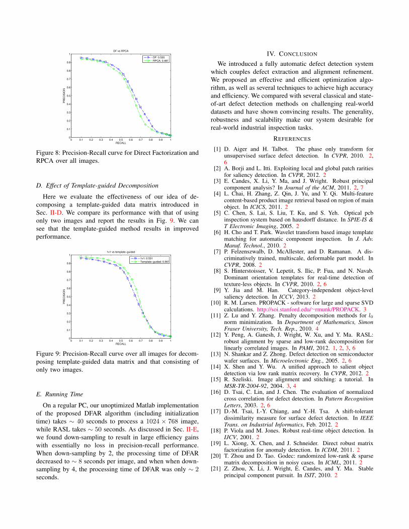
C. Direct Decomposition VS. Robust PCA
One major difference between our work and RASL is,RASL relaxes rank to nuclear norm and l0 norm to l1norm. Here we compare their performance with the samefixed alignments so as to more faithfully evaluate the effectof relaxation. In other words, we remove the alignmentrefinement of our method and that of RASL to reduce itto Robust PCA [3]. We report the results in Fig. 8.
We can see that the original rank minimization can indeedachieve better performance than the relaxed version withreasons analogous to that analyzed in Sec. III-B.
0 0.1 0.2 0.3 0.4 0.5 0.6 0.7 0.8 0.9 10
0.1
0.2
0.3
0.4
0.5
0.6
0.7
0.8
0.9
1
RECALL
PR
EC
ISIO
N
DF vs RPCA
DF: 0.520
RPCA: 0.481
Figure 8: Precision-Recall curve for Direct Factorization andRPCA over all images.
D. Effect of Template-guided Decomposition
Here we evaluate the effectiveness of our idea of de-composing a template-guided data matrix introduced inSec. II-D. We compare its performance with that of usingonly two images and report the results in Fig. 9. We cansee that the template-guided method results in improvedperformance.
0 0.1 0.2 0.3 0.4 0.5 0.6 0.7 0.8 0.9 10
0.1
0.2
0.3
0.4
0.5
0.6
0.7
0.8
0.9
1
RECALL
PR
EC
ISIO
N
1v1 vs template−guided
1v1: 0.531
Template−guided: 0.561
Figure 9: Precision-Recall curve over all images for decom-posing template-guided data matrix and that consisting ofonly two images.
E. Running Time
On a regular PC, our unoptimized Matlab implementationof the proposed DFAR algorithm (including initializationtime) takes ∼ 40 seconds to process a 1024 × 768 image,while RASL takes ∼ 50 seconds. As discussed in Sec. II-E,we found down-sampling to result in large efficiency gainswith essentially no loss in precision-recall performance.When down-sampling by 2, the processing time of DFARdecreased to ∼ 8 seconds per image, and when when down-sampling by 4, the processing time of DFAR was only ∼ 2seconds.
IV. CONCLUSION
We introduced a fully automatic defect detection systemwhich couples defect extraction and alignment refinement.We proposed an effective and efficient optimization algo-rithm, as well as several techniques to achieve high accuracyand efficiency. We compared with several classical and state-of-art defect detection methods on challenging real-worlddatasets and have shown convincing results. The generality,robustness and scalability make our system desirable forreal-world industrial inspection tasks.
REFERENCES
[1] D. Aiger and H. Talbot. The phase only transform forunsupervised surface defect detection. In CVPR, 2010. 2,6
[2] A. Borji and L. Itti. Exploiting local and global patch raritiesfor saliency detection. In CVPR, 2012. 2
[3] E. Candes, X. Li, Y. Ma, and J. Wright. Robust principalcomponent analysis? In Journal of the ACM, 2011. 2, 7
[4] L. Chai, H. Zhang, Z. Qin, J. Yu, and Y. Qi. Multi-featurecontent-based product image retrieval based on region of mainobject. In ICICS, 2011. 2
[5] C. Chen, S. Lai, S. Liu, T. Ku, and S. Yeh. Optical pcbinspection system based on hausdorff distance. In SPIE-IS &T Electronic Imaging, 2005. 2
[6] H. Cho and T. Park. Wavelet transform based image templatematching for automatic component inspection. In J. Adv.Manuf. Technol., 2010. 2
[7] P. Felzenszwalb, D. McAllester, and D. Ramanan. A dis-criminatively trained, multiscale, deformable part model. InCVPR, 2008. 2
[8] S. Hinterstoisser, V. Lepetit, S. Ilic, P. Fua, and N. Navab.Dominant orientation templates for real-time detection oftexture-less objects. In CVPR, 2010. 2, 6
[9] Y. Jia and M. Han. Category-independent object-levelsaliency detection. In ICCV, 2013. 2
[10] R. M. Larsen. PROPACK - software for large and sparse SVDcalculations. http://soi.stanford.edu/∼rmunk/PROPACK. 3
[11] Z. Lu and Y. Zhang. Penalty decomposition methods for l0norm minimization. In Department of Mathematics, SimonFraser University, Tech. Rep., 2010. 4
[12] Y. Peng, A. Ganesh, J. Wright, W. Xu, and Y. Ma. RASL:robust alignment by sparse and low-rank decomposition forlinearly correlated images. In PAMI, 2012. 1, 2, 3, 6
[13] N. Shankar and Z. Zhong. Defect detection on semiconductorwafer surfaces. In Microelectronic Eng., 2005. 2, 6
[14] X. Shen and Y. Wu. A unified approach to salient objectdetection via low rank matrix recovery. In CVPR, 2012. 2
[15] R. Szeliski. Image alignment and stitching: a tutorial. InMSR-TR-2004-92, 2004. 3, 4
[16] D. Tsai, C. Lin, and J. Chen. The evaluation of normalizedcross correlation for defect detection. In Pattern RecognitionLetters, 2003. 2, 6
[17] D.-M. Tsai, I.-Y. Chiang, and Y.-H. Tsa. A shift-tolerantdissimilarity measure for surface defect detection. In IEEETrans. on Industrial Informatics, Feb. 2012. 2
[18] P. Viola and M. Jones. Robust real-time object detection. InIJCV, 2001. 2
[19] L. Xiong, X. Chen, and J. Schneider. Direct robust matrixfactorization for anomaly detection. In ICDM, 2011. 2
[20] T. Zhou and D. Tao. Godec: randomized low-rank & sparsematrix decomposition in noisy cases. In ICML, 2011. 2
[21] Z. Zhou, X. Li, J. Wright, E. Candes, and Y. Ma. Stableprincipal component pursuit. In ISIT, 2010. 2