directional coupler
TRANSCRIPT
A Design of Microstrip Directional Coupler for High Directivity andTight Coupling
Chul-Soo Kim, Young-Tae Kim, Seung-Hoon Song*, Wan-Soo Jung*, Kwang-Yong Kang**Jun-Seok Park, and Dal Ahn
Div. of Information Technology Eng., Soonchunhyang Univ., Chungnam, R.O.Korea*Netel Inc. Seoul, R.O.Korea
**Telecommunication Basic Research Lab., ETRI, R.O.KoreaE-mail: dahrLa,ramrec.sch.ac.kr
ABSTRACT
In this paper, we presented a novel structure ofmicrostrip directional coupler for realizing the highdirectivity characteristic and tight coupling. Theachievement of the high directivity with microstripconfiguration was carried out by matching the even andodd mode effective phase velocities. By using 2-dimensional finite element(FE) calculations, the phasevelocity for each mode and design parameters wereextracted for given dimensions. Based on the extracteddesign parameter with phase matched condition, wedesigned and fabricated 3dB and 4.7dB directional couplerat 2.0GHz. Experimental results of microstrip couplershow good performance with excellent isolationcharacteristics.
INTRODUCTION
Directional couplers with parallel microstrip coupledtransmission line are widely utilized for various RF andmicrowave applications because they can be easilyincorporated into and implemented with other circuits.However, the microstrip directional couplers suffer frompoor directivity due to characteristic of the inhomogeneousdielectric including both dielectric substrate and air inmicrostrip transmission lines. Thus, the phase velocity ofeven mode in microstrip is not equal to that of odd mode.The directivity performance of microstrip directionalcoupler becomes worse when the coupling is decreased orthe dielectric permittivity is increased.[1] In addition, it isdifficult to achieve tight coupling owing to impracticalspacing between the coupled lines in conventional edgecoupled microstrip couplers. These are reasons for usingthe broad-side stripline configuration for tight couplingand high directivity, which needs more fabrication cost andefforts than a conventional microstrip line coupler.
Several techniques are available to equalize orcompensate for the inequality in the each mode velocity ofthe coupled microstrip line. The wiggly-line coupler firstproposed by Podell suffers from a lack of pertinent designinformation.[2] Dielectric overlays have also been used toequalize the mode phase velocities by increasing the oddmode effective dielectric constant.[3] The capacitively andinductively compensated directional couplers with highdirectivity were used to equalize the phase velocities.[4]Re-entrant mode coupler was proposed by S. B. Cohn toobtain tight coupling. [5]
In this paper, a novel structure of microstripdirectional coupler is presented to achieve high directivityand tight coupling, which has 3dB coupling and more -
30dB isolation. To equalize the each mode phase velocity,we used the capacitive compensation method with parallelcoupled microstrip line and additional lumped capacitorfabricated using dielectric substrate. The lumped capacitorof the presented structure can be achieved by reducing thedifference between the even and odd mode phase velocitiesfor the coupled microstrip line. Based on 2-D finiteelement(FE) calculations, the phase velocity for each modeand design parameters were extracted for given dimensions.In order to show the effectiveness of newly proposedcoupled line structure with additional capacitance, wedesigned and fabricated a directional coupler to achievethe tight coupling of 3dB and 4.7dB with high directivityof 32dB and 3 1 dB, respectively.
DESIGN PROCEDURE
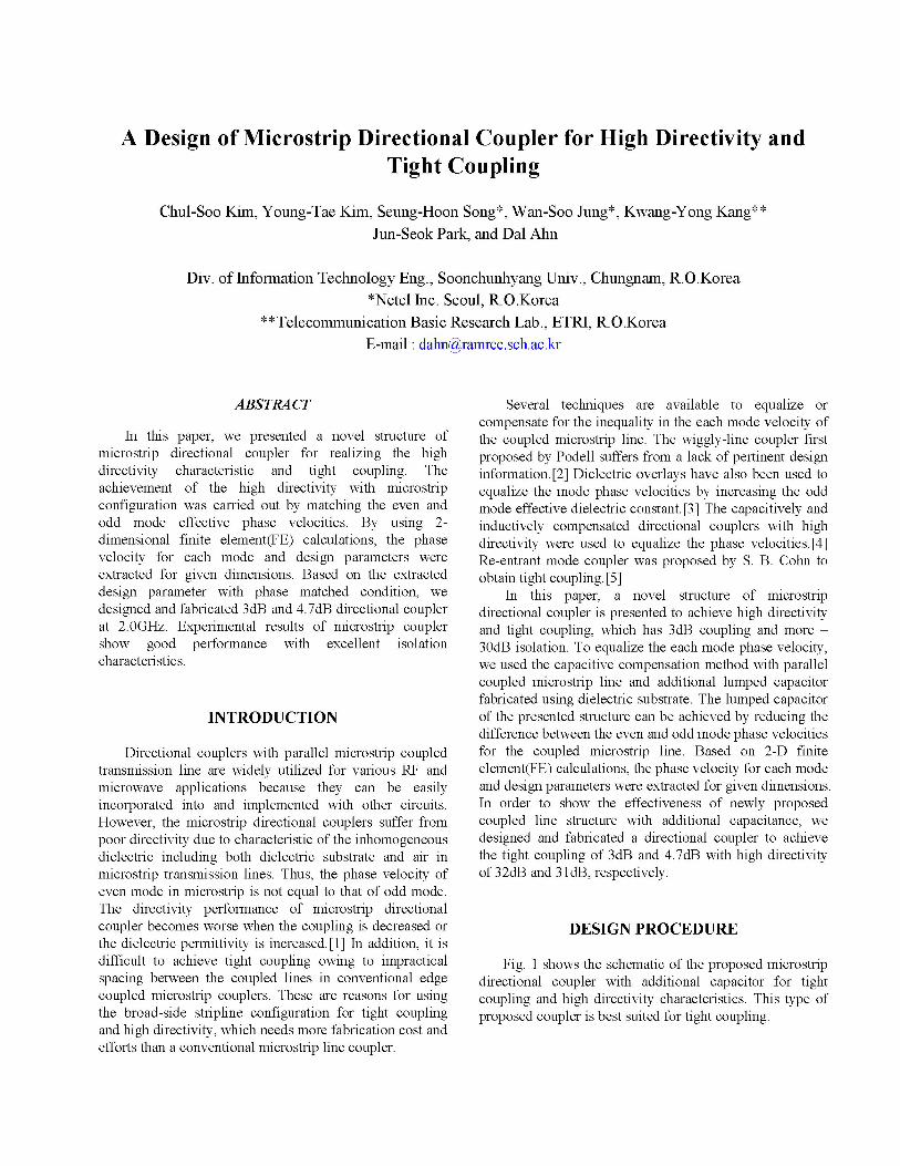
Fig. 1 shows the schematic of the proposed microstripdirectional coupler with additional capacitor for tightcoupling and high directivity characteristics. This type ofproposed coupler is best suited for tight coupling.
Zo oeZoo
k = Zoe zoo =1 -ZoiZoe +Zoo Z02 +ZO I
Zoe=ZX 1+k Z =Z kZO 1O-k and Z00Z0+
Fig. 1 Schematic of the proposed microstrip directionalcoupler
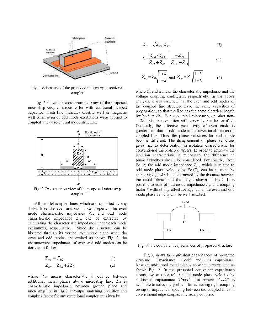
Fig. 2 shows the cross sectional view of the proposedmicrostrip coupler structure for with additional lumpedcapacitor. Dash line indicates electric wall or magneticwall when even or odd mode excitations were applied tocoupled line of re-entrant mode structure.
A Electric wall or
magnetic wall
A'Fig. 2 Cross section view of the proposed microstrip
coupler
All parallel-coupled lines, which are supported by anyTEM, have the even and odd mode property. The even
mode characteristic impedance Zoe and odd modecharacteristic impedance ZOO can be extracted bycalculating the characteristic impedance under each modeexcitations, respectively. Since the structure can bebisected through its vertical symmetric plane when theeven and odd modes are excited as shown Fig. 2, thecharacteristic impedances of even and odd modes can bederived as follow
Zoe = Z02zoo=Z02+2ZOl
(1)
(2)
where Zol means characteristic impedance betweenadditional metal planes above microstrip line, Z02 iScharacteristic impedance between ground plane andmicrostrip line in Fig 2. In/output matching condition andcoupling factor for any directional coupler are given by
where ZO and k mean the characteristic impedance and thevoltage coupling coefficient, respectively. In the aboveanalysis, it was assumed that the even and odd modes ofthe coupled line structure have the same velocities ofpropagation, so that the line has the same electrical lengthfor both modes. For a coupled microstrip, or other non-TEM, this line condition will generally not be satisfied.Generally, the effective permittivity of even mode isgreater than that of odd mode in a conventional microstripcoupled line. Thus, the phase velocities for each modebecome different. The disagreement of phase velocitiesgives rise to deterioration in isolation characteristic forconventional microstrip couplers. In order to improve theisolation characteristic in microstrip, the difference inphase velocities should be considered. Fortunately, FromEq.(2) the odd mode impedance ZOO, which is related toodd mode phase velocity by Eq.(7), can be adjusted bychanging Zol, which is determined by the distance betweenthe metal planes and the height shown in Fig.2. It ispossible to control odd mode impedance ZOO and couplingfactor k without any effect for Zoe. Thus, the even and oddmode phase velocity can be well matched.
Cadd
Cb
Ca Ca-
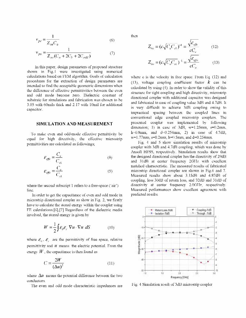
Fig. 3 The equivalent capacitances of proposed structure
Fig 3. shows the equivalent capacitances of presentedstructure. Capacitance 'Cadd' indicates capacitancebetween additional metal planes above microstrip line asshown Fig. 2. In the presented equivalent capacitancecircuit, we can control the odd mode phase velocity byadditional capacitance 'Cadd'. Furthermore 'Cadd' isavailable to solve the problem for achieving tight couplingowing to impractical spacing between the coupled lines inconventional edge coupled microstrip couplers.
(3)
(4)
(5)
1V =
oe a
Zoo (Ca + 2Cb + 2Cadd)
(6)
(7)
In this paper, design parameters of proposed structureshown in Fig. 1 were investigated using numericalcalculations based on FEM algorithm. Goals of calculationprocedures for the extraction of design parameters areintended to find the acceptable geometric dimensions whenthe difference of effective permittivities between the evenand odd mode become zero. Dielectric constant ofsubstrate for simulations and fabrication was chosen to be3.05 with 60mils thick and 2.17 with 1Omil for additionalcapacitor.
SIMULATION AND MEASUREMENT
To make even and odd-mode effective permittivity beequal for high directivity, the effective microstrippermittivities are calculated as followings;
_Ce£effe C
el
r - CoCeffoCol
(8)
(9)
where the second subscript 1 refers to a free-space ('air')line.
In order to get the capacitance of even and odd mode inmicrostrip directional coupler as show in Fig. 2, we firstlyhave to calculate the stored energy within the coupler usingFE calculations.[6],[7] Regardless of the dielectric mediainvolved, the stored energy is given by
then
Z = (C CeCel)-I 8effe
ZO =(cC0C1) c't,effoZOO=( Cooo -cC0
(12)
(13)
where c is the velocity in free space. From Eq. (12) and(13), voltage coupling coefficient factor k can becalculated by using (4). In order to show the validity of thisstructure for tight coupling and high directivity, microstripdirectional coupler with additional capacitor was designedand fabricated in case of coupling value 3dB and 4.7dB. Itis very difficult to achieve 3dB coupling owing toimpractical spacing between the coupled lines inconventional edge coupled microstrip couplers. Thepresented coupler was implemented by followingdimension; 1) in case of 3dB, w=1.25mm, s=0.2mm,h=0.8mm, and d=0.254mm, 2) in case of 4.7dB,w=1.77mm, s=0.2mm, h=0.5mm, and d=0.254mm.
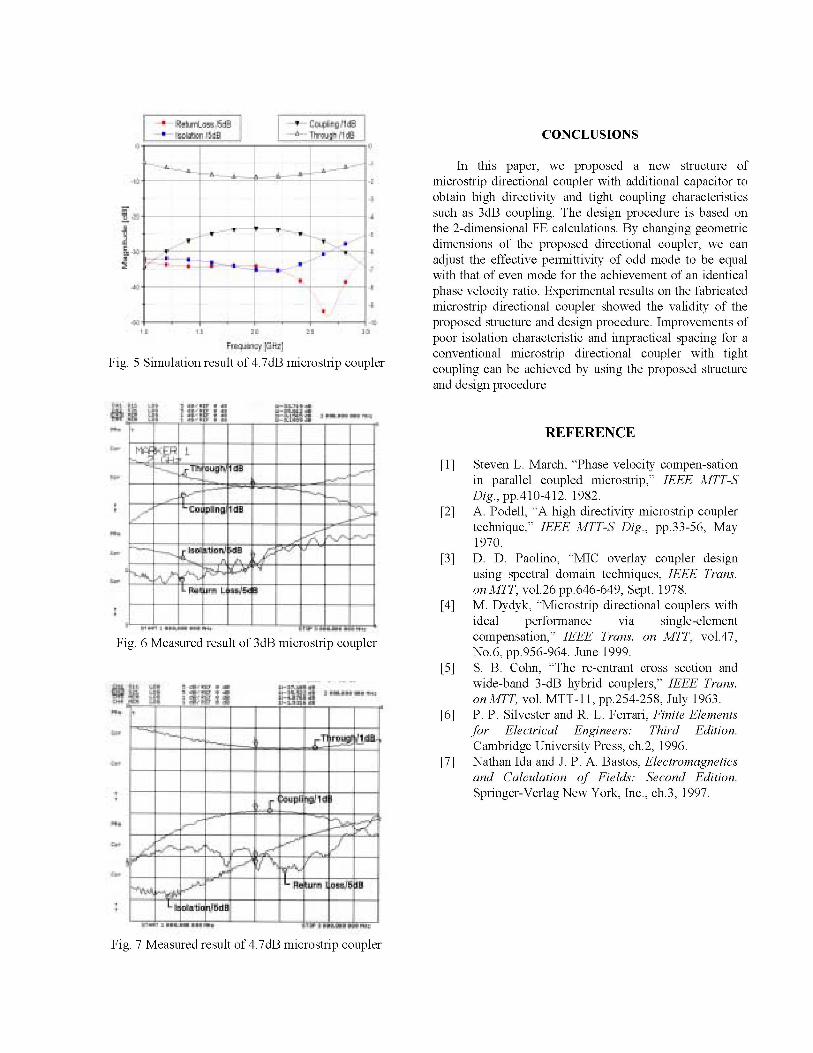
Fig. 4 and 5 show simulation results of microstripcoupler with 3dB and 4.7dB coupling, which was done byAnsoft HFSS, respectively. Simulation results show thatthe designed directional coupler has the directivity of 29dBand 3 1dB at center frequency 2GHz with excellentmatched characteristic. The measured results of fabricatedmicrostrip directional coupler are shown in Fig.6 and 7.Measured results show about 3.15dB and 4.87dB ofcoupling, less 30dB of return loss, and 32dB and 31dB ofdirectivity at center frequency 2.0GHz, respectively.Measured performances show excellent agreement withpredicted results.
W=-|I0Or Vu*Vu dS2"
where CO, Er are the permittivity of free space, relativepermittivity and u means the electric potential. From theenergy W, the capacitance is then found as
C =2W(Au)2
(10)&~~~~~~~ a
Im ...,I
...
(1 1)
where Au means the potential difference between the twoconductors.
The even and odd mode characteristic impedances are Fig. 4 Simulation result of 3dB microstrip coupler
v
Y
CONCLUSIONS
.4
Fig. 5 Simulation result of 4.7dB microstrip coupler
1. m .... I i la -L f
"l~~~1 19Is.ZN2._* _1g g g-LMI. S .. W m X Ir ......... W X S. .. . .....72_;; g ........ 41ffi ,_ L .............................. 11 _ 4I I b 6g I IS X E u gg--..
Fig. 6 Measured result of 3dB microstrip coupler
In this paper, we proposed a new structure ofmicrostrip directional coupler with additional capacitor toobtain high directivity and tight coupling characteristicssuch as 3dB coupling. The design procedure is based onthe 2-dimensional FE calculations. By changing geometricdimensions of the proposed directional coupler, we canadjust the effective permittivity of odd mode to be equalwith that of even mode for the achievement of an identicalphase velocity ratio. Experimental results on the fabricatedmicrostrip directional coupler showed the validity of theproposed structure and design procedure. Improvements ofpoor isolation characteristic and impractical spacing for aconventional microstrip directional coupler with tightcoupling can be achieved by using the proposed structureand design procedure
REFERENCE
[1] Steven L. March, "Phase velocity compen-sationin parallel coupled microstrip," IEEE MTT-SDig., pp.410-412. 1982.
[2] A. Podell, "A high directivity microstrip couplertechnique," IEEE MTT-S Dig., pp.33-56, May1970.
[3] D. D. Paolino, "MIC overlay coupler designusing spectral domain techniques, IEEE Trans.on MTT, vol.26 pp.646-649, Sept. 1978.
[4] M. Dydyk, "Microstrip directional couplers withideal performance via single-elementcompensation," IEEE Trans. on MTT, vol.47,No.6, pp.956-964. June 1999.
[5] S. B. Cohn, "The re-entrant cross section andwide-band 3-dB hybrid couplers," IEEE Trans.on MTT, vol. MTT-1 1, pp.254-258, July 1963.
[6] P. P. Silvester and R. L. Ferrari, Finite Elementsfor Electrical Engineers: Third Edition.Cambridge University Press, ch.2, 1996.
[7] Nathan Ida and J. P. A. Bastos, Electromagneticsand Calculation of Fields: Second Edition.Springer-Verlag New York, Inc., ch.3, 1997.
Fig. 7 Measured result of 4.7dB microstrip coupler
IP 'tt isdB
gF 4If
IdL
....