directional coupler based on twin-core fiber. bilal... · directional coupler based on twin-core...
TRANSCRIPT

Directional Coupler Based on Twin-Core Fiber
Bilal A. Alvi, Amber Israr, and Muhammad Aamir
Electrical Engineering Department, Institute of Business Management, Karachi,
Sir Syed University of Engineering & Technology, Karachi, Pakistan

Agenda
• Introduction
• Background
• Twin Core Optical Fiber
• Calculation of Antisymmetric Mode Cutoff
• Experimental Set up
• Conclusion

Introduction
• Optical communications uses a fiber basically as an information carrying line between electronic component.
• There is steady progress towards optical manipulation of signal.
• Perhaps fiber couplers are the simplest and the most important devices in fiber communication applications.

Directional Coupler • The Coupler allows an incoming
signal to be split between 2 out put fibers.
• Rely on Evanescent wave coupling
– Two waveguides close together
– Evanescent field of first waveguide “feels” second waveguide
– Gradual coupling of light between both waveguides
– Power transfer ratio P1/P2 depends on the core spacing and on the interaction length

Application
• Power Divider
• Passive filters
• Wavelength multiplexers/Demultiplexers
• Combiner
• Fiber sensors,
• Fiber Amplifier
• Switches

Coupler Construction Techniques • Several techniques have been developed to
construct couplers: – Polished cladding couplers
• Advantages: Wavelength-tunable
• Disadvantages: Unstable
– Fusion elongation techniques • Mechanically stable
• Difficult to handle
– Chemical etching • Handling more intangible, and high losses
– Multi-cored fibers • core to core spacing controlled, free from undesirable
birefringence
• Difficult to couple light

Twin core optical Fiber
• Twin core fiber consist of a pair of identical cores embedded in cladding with slight lower index, ncl, that of the core, nco.
• The center to center spacing is d.
2a 2a
d

Advantages
• Geometrical Dimension
– Control of core to core spacing
• Undesirable generation of birefringence can be avoided
• No reference fiber required for interferometry applications
• Eliminate many optical devices in optical set up.

Twin core Fiber Coupling Process • The optical coupling in twin core fiber was analyzed in terms of
linear combination of symmetric and antisymmetric modes . • Figure below illustrate the Geometry of twin-core fiber. • Two straight circular cores of same diameter, r, are embedded in
same cladding • The center to center spacing is d. • Refractive index profile n(r).

Processes in Isolation
• In isolation each core behaves as single mode fiber and field can be constructed from the scalar wave equation.
• There is no narrowing of the cores so light is still well guided.

• In case of twin core, the symmetry of composite wave guide doubles the number of modes.
• Thus two fundamental solution of the scalar wave equation required.
• These are the symmetric and antisymmetric superposition of the field in the two cores in isolation. Ψ+ =Ψ1 + Ψ2 : Ψ- =Ψ1 – Ψ2
• Where Ψ1 and Ψ2 are the fundamental
solution for each fiber in solution, referred to common axes
• Due to the unequal propagation constant of two modes, the fields propagating down the system develop a relative phase difference with the distance.
• Just as with the normal modes of a circular waveguide, Ψ+ is not cut off and Ψ- has finite cut off.
• Beyond the cut off Ψ- ,, it becomes radiative mode and is attenuated.
Ψ+
Ψ-

Calculation of Cutoff Conditions • A variation calculation was used to calculate the cut-off
condition for the antisymmetric mode. • The eigen-value problem for the twin-core structure
shown in above Figure has been solved by variation of the trial function
where r is the variational parameter, Es is the symmetric mode and EA is the anti-symmetric mode.
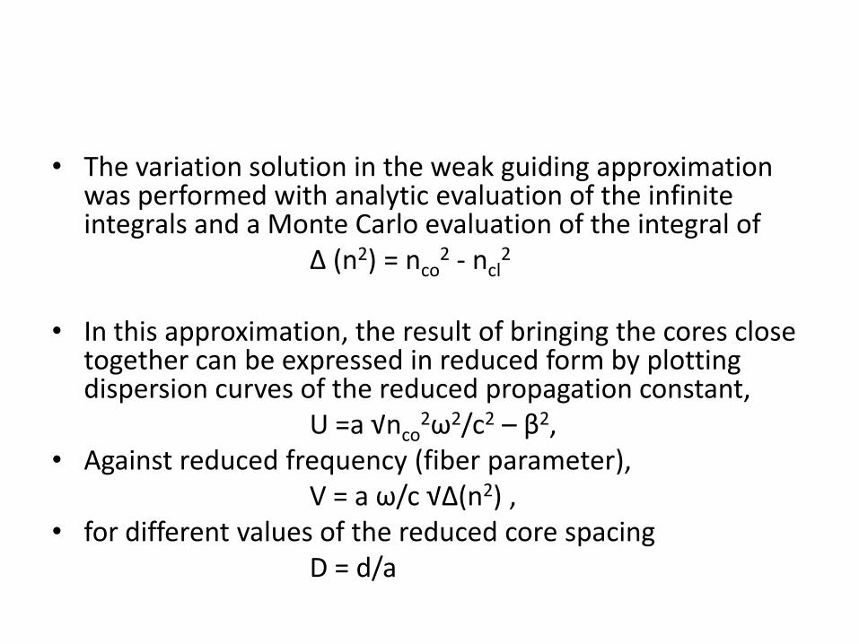
• The variation solution in the weak guiding approximation was performed with analytic evaluation of the infinite integrals and a Monte Carlo evaluation of the integral of
∆ (n2) = nco2 - ncl
2 • In this approximation, the result of bringing the cores close
together can be expressed in reduced form by plotting dispersion curves of the reduced propagation constant,
U =a √nco2ω2/c2 – β2,
• Against reduced frequency (fiber parameter), V = a ω/c √∆(n2) , • for different values of the reduced core spacing D = d/a
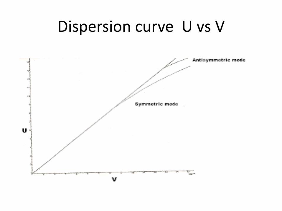
Dispersion curve U vs V

Experimental Results
• Twin-cored fibers were prepared by the rod and tube method from laboratory Pyrex cladding (ncl = 1.474) and Schott ZKN7 zinc crown optical glass core (nco = 1.506).
• Core diameter is 1.5µm • Core separation is 6µm • The core diameters were such as to satisfy the
single mode condition for each core considered separately, that is to say that the fiber parameter, V, was less than 2.405
•

Phase Contrast Image

Near field Image
• Figure shows, when the cores of the fiber were equally excited with a HeNe laser.
• The cores of twin core were sufficiently well separated for their fundamental modes to be phase mismatched so that significant coupling between cores was avoided.

Far Field Image
• Figure shows, far field expected sine-squared-theta fringes.

Bi-conical Taper
• The next step was the introduction of bi-conical taper in a fiber with well separated cores, the waist diameter in the taper being chosen to ensure cutoff of the antisymmetric mode.
• The technique used for making a taper was that of “heating and pulling”.
• Taper waist “25 µm” and taper length “3.5 cm”
• The bi-conical taper provides 3dB splitting between the two cores of the symmetric part of the input excitation.

Experimental Set-up
• A schematic diagram of the experimental set up is shown in figure in next slide
• System consist of
– Light source
– Beam coupling system
– Fiber
– Recording system
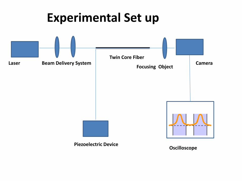
Laser Beam Delivery System
Piezoelectric Device
Focusing Object
Oscilloscope
Camera Twin Core Fiber
Experimental Set up

Coupler’s Operation
• Three important section
– An entrance down-tapering conical section
– A central section
– An exit up-tapering conical section

Coupler’s Operation

Entrance down-tapering section
• The transmission through a entrance fiber is due to the fundamental core mode.
• While propagating down the taper, the wave encounters a gradually reduction of d, the tail of the isolated guide modes begin to overlap
• Which split the fundamental mode into two modes, Symmetric and antisymmetric mode
• Interference take place between the two modes as they propagate with different phase velocity through down taper section and result in power transfer between the core.
• When these modes are in phase the energy in core 1 • When these modes are out of phase the energy in core 2.

A central section
• Taper diameter is less and the cores are very thin and almost touching each other.
• Their ratio d/a is equal to 3 and V parameter less than about 1.
• The lowest order antisymmetric mode of this composite structure cut off as shown in dispersion curve.
• While symmetric super mode propagate through the centre region

Exit up-tapering conical section
• As the light propagates beyond the point of minimum cross section of the taper, it eventually encounters the up-taper, where the size of the core progressively increases.
• In this region the V parameter of the core is again approximately equal to 1.

50-50 splitting

Conclusion
• The experimental results reported, firm evidence for the feasibility of fabricating in-fiber splitting (and combining) components for single fiber interferometers .
• The inclusion of reference and measured paths within a single fiber offers the prospect of fiber interferometry with much reduced sensitivity to temperature induced noise and drift.
• Ultimately it may even be possible to incorporate fluorescent source and detector sections within a single fiber and so achieve true intelligent measurement systems within a self-contained fiber structure.

Acknowledgment
• Prof. Dr. Bhawani Shankar Chowdhry for his technical and moral support
• Mr. Shah Jahan Karim President of Institute of Business Management for providing financial assistance

References 1. Van Leeuwen, T. N., Visser, M. S., Moed, H. F., Nederhof, T T. Ozeki and B.S. Kawasaki,
Electron letter., Volum. 12, pp.151,1976 2. F.J.Michel, J.S.Herbert, J. Quantum Electronics, Vol. QE-18, pp. 746, 1982 3. A.Yariv, "Optical Electronics", Holt-Saunders, New York, 1985, pp. 442. 4. G.Meltz, J.R.Dunphy, W.W.Morey and E.snitzer, Appl.Optics, 22, 464-477, 1983. 5. A. W. Snyder, and J. D. Love, Optical Waveguide Theory, Chappman and Hall, London,
1983. 6. Y. Tsujimoto, H. Serizawa, K. Hattori and M. Fukai, Electron Letter, Vol. 14, pp.157,1978. 7. S. Inao, T. Sato, H. Hondo, M. Ogai, K. Yoshizaki, K. Ishihara, and N. Uchida, Proc. Int. Wire
& Cable Symposium (IWCS), 1979, pp. 370–384. 8. Xiaoliang Zhu, Libo Yuan, Zhihai Liu, Jun Yang, and Chunying Guan, J. Lightw. Technol., vol.
27,no. 23, pp.5235-5239, 2009. 9. P. Jacob, C. Anne, and R. Vallee, Appl. Opt., vol. 36, no. 21, pp.5064–5071, Jul. 1997. 10. M. Fokine, L. E. Nilsson, A. Claesson, D. Berlemont, L. Kjellberg, L. Krummenacher, and W.
Margulis, “Integrated fiber Mach–Zehnder interferometer for electrooptic switching,” Opt. Lett., vol. 27, no. 18, pp. 1643–1645, 2002.
11. Rosingski, J. W. D. Chi, P. Grosso, and J. L. Bihan, J. Lightw. Technol., vol. 17, no. 5, pp. 807–810, 1999.
12. P. Glas, M. Naumann, A. Schirrmacher, and T. Pertsch, Opt. Commun., vol. 151, no. 1, pp. 187–195, 1998.
13. M. Wrage, P. Glas, D. Fischer,M. Leitner, N. N. Elkin, D. V. Vysotsky, A. P. Napartovich, and V. N. Troshchieva, Opt. Commun., vol. 205, no. 4–6, pp. 367–375, May 2002.

Thank You