directional spool valves, direct operated, , edition , bosch rexroth ag directional spool valves,...
TRANSCRIPT

RE 23164, edition: 2013-01, Bosch Rexroth AG
Directional spool valves, direct operated, with solenoid actuation
Features
▶ 4/3-, 4/2- or 3/2-way version ▶ Standard version ▶ Porting pattern according to DIN 24340 form A ▶ Wet-pin DC solenoids ▶ Rotatable solenoid coil ▶ The coil can be changed without having to open the
pressure-tight chamber ▶ Electrical connection as individual connection ▶ Concealed manual override
▶ Size 6 ▶ Component series 7X ▶ Maximum operating pressure 315 bar ▶ Maximum flow 60 l/min
RE 23164 Edition: 2013-01Replaces: 07.06
H7380
Type WE
Contents
Features 1Ordering code 2Symbols 3Function, section 4Technical data 5, 6Characteristic curves 7Switching power limits 7Device dimensions 8 … 10Mating connectors 10More information 10
Inhalt
Features 1Ordering code 2Symbols 3Function, section 4Technical data (For applications outside these parameters, please consult us!) 5Technical data (For applications outside these parameters, please consult us!) 6Characteristic curves (measured with HLP46, ϑoil = 40 ± 5 °C) 7Switching power limits (measured with HLP46, ϑoil = 40 ± 5 °C) 7Unit dimensions: Version "K4" (dimensions in mm) 8Unit dimensions: Version "C4Z" (dimensions in mm) 9Unit dimensions 10Mating connectors according to DIN EN 175301-803 10More information 10Notes 11Notes 12

2/10 WE | Directional spool valve
Bosch Rexroth AG, RE 23164, edition: 2013-01
Ordering code
01 3 main ports 3
4 main ports 4
02 Directional valve WE
03 Size 6 6
04 Symbols e.g. D, E etc.; possible design see page 3
05 Component series 70 … 79 (70 … 79: Unchanged installation and connection dimensions) 7X
06 With spring return no code
Without spring return with detent OF 1)
07 Standard solenoid, wet-pin H
08 Direct voltage 12 V G12
Direct voltage 24 V G24
09 With concealed manual override N9
Electrical connection
10 Individual connection
Without mating connector with connector DIN EN 175301-803 K4 2)
Without mating connector with connector AMP Junior-Timer C4Z 2)
Seal material
11 NBR seals no code
(other seals upon request) Attention! Ensure compatibility of seals with hydraulic fluid used!
12 Further details in the plain text
01 02 03 04 05 06 07 08 09 10 11 12
WE 6 7X / H N9 / *
Preferred types and standard units are contained in the EPS (standard price list).
1) Only symbol D 2) Mating connectors, separate order, see page 10 and
data sheet 08006.

�
�
� � � �
� �
� �� �
���
���
���
� �
� �
� �
� �
� �
� �� �
���
���
�
�
� � ������������ �
� �
� �� �
�
�
�
�
������
���
� �
� �
� � � �
� �
� �
� �� �
���
���
� �
� �
� � � �
� �
� ��
� �
� �
� �
� �
� �
� � �
�������
����
Directional spool valve | WE 3/10
RE 23164, edition: 2013-01, Bosch Rexroth AG
1) Only symbol D2) Example:
Symbol E with switching position "a" ordering code ..EA..
Symbols

� �����
� �
��� �
� ��
��� ���
�
4/10 WE | Directional spool valve
Bosch Rexroth AG, RE 23164, edition: 2013-01
Function, section
Directional valves of type WE are solenoid operated direc-tional spool valves. They control the start, stop and direc-tion of a flow.The directional valves basically consist of housing (1), one or two solenoids (2), control spool (3), and one or two return springs (4).In the de-energized condition, control spool (3) is held in the central position or in the initial position by the return springs (4). The control spool (3) is actuated by wet-pin solenoids (2).
For proper functioning, it must be ensured that the sole-noid's pressure chamber is filled with oil!
Type 4WE 6 E7X/H…
The force of solenoid (2) acts via plunger (5) on control spool (3) and pushes the latter from its rest position to the required end position. This opens up the required flow direction according to the spool symbol.After solenoid (2) has been de-excited, return spring (4) pushes control spool (3) back to its rest position again.The manual override (6) allows control spool (3) to be moved without solenoid energization.

Directional spool valve | WE 5/10
RE 23164, edition: 2013-01, Bosch Rexroth AG
hydraulic
Maximum operating pressure – Port A, B, P bar 315
– Port T bar 160 With symbols A and B, port T must be used as leakage port if the operating pressure exceeds the permissible tank pressure.
Maximum flow l/min 60
Hydraulic fluid See table below
Hydraulic fluid temperature range °C –30 … +80
Viscosity range mm2/s 2.8 … 500
Maximum permitted degree of contamination of the hydraulic fluid - cleanliness class according to ISO 4406 (c)
Class 20/18/15 1)
Technical data (For applications outside these parameters, please consult us!)
1) The cleanliness classes specified for the components must be adhered to in hydraulic systems. Effective filtration prevents faults and at the same time increases the life cycle of the components.
For the selection of the filters see www.boschrexroth.com/filter.
Notice! ▶ Only actuate the manual override using a rounded tool (Ø3+1 mm) or special tool (separate order, mate-rial no. R900024943)!
▶ Actuation of the manual override only up to a tank pressure of approx. 50 bar.
▶ When the manual override is blocked, the operation of the solenoid must be prevented!
▶ The simultaneous operation of the solenoids must be prevented!
general
Weight – Valve with 1 solenoid kg Approx. 1.25
– Valve with 2 solenoids kg Approx. 1.6
Installation position Any
Ambient temperature range °C –30 … +50
Hydraulic fluid Classification Suitable sealing materials StandardsMineral oils HL, HLP, HLPD, HVLP, HVLPD NBR, FKM DIN 51524
Bio-degradable– insoluble in water
HETG NBR, FKMVDMA 24568
HEES FKM
– soluble in water HEPG FKM VDMA 24568
Flame-resistant– water-free HFDU, HFDR FKM ISO 12922
– containing waterHFC (Fuchs Hydrotherm 46M, Petrofer Ultra Safe 620)
NBR ISO 12922
Important information on hydraulic fluids! ▶ For more information and data on the use of other hydraulic fluids refer to data sheet 90220 or contact us!
▶ There may be limitations regarding the technical valve data (tem-perature, pressure range, life cycle, maintenance intervals, etc.)!
▶ The flash point of the hydraulic fluid used must be 40 K higher than the maximum solenoid surface temperature.
▶ Flame-resistant – containing water: – Maximum pressure differential per control edge 50 bar – Pressure pre-loading at the tank port > 20 % of the pressure differential, otherwise increased cavitation
– Life cycle as compared to operation with mineral oil HL, HLP 50 to 100 %
▶ Bio-degradable: When using bio-degradable hydraulic fluids that are simultaneously zinc-solving, zinc may accumulate in the fluid (per pole tube 700 mg zinc).

6/10 WE | Directional spool valve
Bosch Rexroth AG, RE 23164, edition: 2013-01
electric
Voltage type Direct voltage
Available voltages V 12; 24
Voltage tolerance (nominal voltage) % ±10
Power consumption W 26
Duty cycle S1 (continuous operation)
Switching time ON ms 20 … 45
OFF ms 10 … 25
Maximum switching frequency 1/h 15000
Maximum coil temperature 2) °C 150
Protection class according to EN 60529 IP 65 with mating connector mounted and locked
Insulation class VDE 0580 F
2) Due to the high surface temperatures of the solenoid coils > 50 °C the standards ISO 13732-1 and ISO 4413 must be adhered to and the coils must be equipped with contact protection if required.
When establishing the electrical connection, the protective earthing conductor (PE ) has to be connected correctly.
Technical data (For applications outside these parameters, please consult us!)

����
�
�
�
�
� �� ������ �� ��
��
��
�
�
�
�
� ��
���
�� �� �� �� ��
���
���
�
�
��
� � �
Directional spool valve | WE 7/10
RE 23164, edition: 2013-01, Bosch Rexroth AG
Flow in l/min →
Pres
sure
diff
eren
tial i
n ba
r →
Flow in l/min →
Ope
ratin
g pr
essu
re in
bar
→
Symbol Direction of flow
P–A P–B A–T B–T
A, B 3 3 – –
C 1 1 3 1
D, Y 4 4 3 3
E 3 3 1 1
J 1 1 2 1
G 6 6 7 7
H 2 5 2 2
DC solenoid
Characteristic curve Symbol
1 A, B
2 C, Y
3 E
4 J
5 D
6 G, H
7 D/OF
7 Symbol "H" in central position P – T
8 Symbol "G" in central position P – T
Characteristic curves (measured with HLP46, ϑoil = 40 ± 5 °C)
Switching power limits (measured with HLP46, ϑoil = 40 ± 5 °C)
∆p-qV characteristic curves
Notice!The specified switching power limits are valid for opera-tion with two directions of flow (e.g. from P to A and simultaneous return flow from B to T).Due to the flow forces acting within the valves, the per-missible switching power limit may be considerably lower
with only one direction of flow (e.g. from P to A while port B is blocked)!In such cases, please consult us!The switching power limit was established while the solenoids were at operating temperature, at 10 % undervoltage and without tank preloading.
��
��������
���� �����
����
����
��
���� �������
����
����
��
��
�
�� ����
����
��
��
��
��
�
�
���
�����
���
Rzmax 4
0,01/100
8/10 WE | Directional spool valve
Bosch Rexroth AG, RE 23164, edition: 2013-01
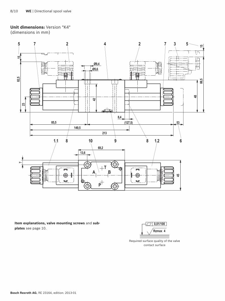
Unit dimensions: Version "K4" (dimensions in mm)
Required surface quality of the valve contact surface
Item explanations, valve mounting screws and sub-plates see page 10.

��
��������
���� �����
����
����
��
���� �������
����
���
��
��
�
���
�
����
��
��
�
�
���
�����
���
����
�
Rzmax 4
0,01/100
Directional spool valve | WE 9/10
RE 23164, edition: 2013-01, Bosch Rexroth AG
Unit dimensions: Version "C4Z" (dimensions in mm)
Required surface quality of the valve contact surface
Item explanations, valve mounting screws and sub-plates see page 10.

Bosch Rexroth AG HydraulicsZum Eisengießer 197816 Lohr am Main, Germany Phone +49 (0) 93 52 / 18-0 [email protected] www.boschrexroth.de
© This document, as well as the data, specifications and other information set forth in it, are the exclusive property of Bosch Rexroth AG. It may not be repro-duced or given to third parties without its consent.The data specified above only serve to describe the product. No statements concerning a certain condition or suitability for a certain application can be derived from our information. The information given does not release the user from the obligation of own judgment and verification. It must be remembered that our products are subject to a natural process of wear and aging.
Bosch Rexroth AG, RE 23164, edition: 2013-01
10/10 WE | Directional spool valve
1.1 Solenoid "a"
1.2 Solenoid "b"
2 Mating connector without circuitry (separate order, see below)
3 Mating connector with circuitry (separate order, see below)
4 Name plate
5 Space required to remove the mating connector
6 Space required to remove the coil
7 Mounting nut, MA = 4+1 Nm
8 Plug screw for valves with one solenoid
9 Identical seal rings for ports A, B, P, and T
10 Porting pattern according to DIN 24340 form A
11 Mating connector "Junior Timer", straight (separate order, see data sheet 08006)
12 Mating connector "Junior Timer", angled (separate order, see data sheet 08006)
Subplates according to data sheet 45052 (separate order) G 341/01 (G1/4) G 342/01 (G3/8) G 502/01 (G1/2)
Valve mounting screws (separate order) ▶ 4 hexagon socket head cap screws ISO 4762 - M5 x 50 - 10.9-flZn-240h-L (friction coefficient µtotal = 0.09 to 0.14); tightening torque MA = 7 Nm ± 10 %, material no. R913000064 or
▶ 4 hexagon socket head cap screws ISO 4762 - M5 x 50 - 10.9 with friction coefficient µtotal = 0.12 to 0.17 a tightening torque MA = 8.1 Nm ± 10 % results (not included in the Rexroth delivery range)
Unit dimensions
More information
▶ Subplates Data sheet 45052
▶ Hydraulic fluids on mineral oil basis Data sheet 90220
▶ General product information on hydraulic products Data sheet 07008
▶ Installation, commissioning and maintenance of industrial valves Data sheet 07300
▶ Hydraulic valves for industrial applications Data sheet 07600-B
▶ Selection of the filters www.boschrexroth.com/filter
Mating connectors according to DIN EN 175301-803
For details and more mating connectors see data sheet 08006
Valve side Color
Material no.
Without circuitryWith indicator light
12 ... 240 VWith rectifier 12 ... 240 V
With indicator light and Zener diode suppression circuit
24 V
a Gray R901017010 – – –
b Black R901017011 – – –
a/b Black – R901017022 R901017025 R901017026

Bosch Rexroth AG HydraulicsZum Eisengießer 197816 Lohr am Main, Germany Phone +49 (0) 93 52 / 18-0 [email protected] www.boschrexroth.de
© This document, as well as the data, specifications and other information set forth in it, are the exclusive property of Bosch Rexroth AG. It may not be repro-duced or given to third parties without its consent.The data specified above only serve to describe the product. No statements concerning a certain condition or suitability for a certain application can be derived from our information. The information given does not release the user from the obligation of own judgment and verification. It must be remembered that our products are subject to a natural process of wear and aging.
Directional spool valve | WE 11/10
RE 23164, edition: 2013-01, Bosch Rexroth AG
Notes
Bosch Rexroth AG HydraulicsZum Eisengießer 197816 Lohr am Main, Germany Phone +49 (0) 93 52 / 18-0 [email protected] www.boschrexroth.de
© This document, as well as the data, specifications and other information set forth in it, are the exclusive property of Bosch Rexroth AG. It may not be repro-duced or given to third parties without its consent.The data specified above only serve to describe the product. No statements concerning a certain condition or suitability for a certain application can be derived from our information. The information given does not release the user from the obligation of own judgment and verification. It must be remembered that our products are subject to a natural process of wear and aging.
Bosch Rexroth AG, RE 23164, edition: 2013-01
12/10 WE | Directional spool valve
Notes